SF D6.7.1 Deployment Programme v1.2 - Safespot€¦ · · 2010-10-26IRIS Intelligent Cooperative...
101
Deliverable 6.7.1 Dissemination Level PU Copyright SAFESPOT Contract N. IST-4-026963-IP SF_D6.7.1_Deployment_Programme_v1.2.doc Page 1 of 101 BLADE SAFESPOT INTEGRATED PROJECT - IST-4-026963-IP DELIVERABLE SP6 – BLADE– Business models, Legal Aspects, and Deployment Deliverable No. (use the number indicated on technical annex) D6.7.1 SubProject No. SP6 SubProject Title Business models, Legal Aspects, and Deployment Workpackage No. WP7 Workpackage Title Deployment programme Task No. T6.7.1 Task Title Formulation of the SAFESPOT deployment programme Authors (per company, if more than one company provide it together) TNO, BASt, CRF, CSST, MMSE, RWS, Thomas Miller, UoA, UoC (see p. 3 for the List of Authors) Status (F: final; D: draft; RD: revised draft): F Version No: 1.2 File Name: SF_D6.7.1_Deployment_Programme_v1.2.doc Planned Date of submission according to TA: 31/11/2009 Issue Date: 31/05/2010 Project start date and duration 01 February 2006, 48 Months The SAFESPOT deployment programme
Transcript of SF D6.7.1 Deployment Programme v1.2 - Safespot€¦ · · 2010-10-26IRIS Intelligent Cooperative...

Deliverable 6.7.1 Dissemination Level PU Copyright SAFESPOT
Contract N. IST-4-026963-IP
SF_D6.7.1_Deployment_Programme_v1.2.doc Page 1 of 101 BLADE
SAFESPOT INTEGRATED PROJECT - IST-4-026963-IP
DELIVERABLE
SP6 – BLADE– Business models, Legal Aspects, and Deployment
Deliverable No. (use the number indicated on technical annex)
D6.7.1
SubProject No. SP6 SubProject Title Business models, Legal Aspects, and Deployment
Workpackage No. WP7 Workpackage Title Deployment programme
Task No. T6.7.1 Task Title Formulation of the SAFESPOT deployment programme
Authors (per company, if more than one company provide it together)
TNO, BASt, CRF, CSST, MMSE, RWS, Thomas Miller, UoA, UoC (see p. 3 for the List of Authors)
Status (F: final; D: draft; RD: revised draft): F
Version No: 1.2
File Name: SF_D6.7.1_Deployment_Programme_v1.2.doc
Planned Date of submission according to TA: 31/11/2009
Issue Date: 31/05/2010
Project start date and duration 01 February 2006, 48 Months
The SAFESPOT deployment programme

Deliverable 6.7.1 Dissemination Level PU Copyright SAFESPOT
Contract N. IST-4-026963-IP
SF_D6.7.1_Deployment_Programme_v1.2.doc Page 2 of 101 BLADE
Revision Log
Version Date Reason Name and Company
0.1 08/01/2010 Index setup Freek Faber(TNO)
0.2 08/01/2010 first draft Freek Faber(TNO)
0.3 01/02/2010 contributions added from CRF and MMSE
Sergio Damiani (CRF)
Piero Mortara (MMSE)
0.4 09/02/2010 Contributions added from BAST and UoC
Roland Schindhelm and Andreas Luedeke
(BASt), Torsten Geissler and
Jan André Buehne (UoC),
0.5 15/02/2010 Executive summary added Contributions added from UoA and RWS
Marion Robery (Thomas Miller), Tom Alkim (RWS), Kiliaan van Wees (
0.6 25/02/2010 Integration of contributions and finalising conclusions & roadmap
Freek Faber (TNO)
0.7 13/03/2010 Review TNO, CRF and MMSE Han Zwijnenberg (TNO), Sergio Damiani (CRF) Piero Mortara(MMSE)
0.8 16/03/2010 Comments BLADE-review processed
Freek Faber (TNO)
1.0 31/05/2010 Comments SAFESPOT review processed
Freek Faber (TNO)
1.1 08/06/2010 Minor issue fixed in the list of figures; overall peer reading and approval from the IP management
Giulio Vivo (CRF)
1.2 01/09/2010 Comments final review processed Freek Faber, Han Zwijnenberg (TNO)
List of Authors
Company Name
TNO (WP-leader) Freek Faber (main author), Martijn de Kievit, Han Zwijnenberg
BASt Andreas Luedeke
Roland Schindhelm
CRF Sergio Damiani
CSST Stefano Marco
MMSE Piero Mortara
RWS Tom Alkim
Thomas Miller Marion Robery
UoA Kiliaan van Wees
UoC Torsten Geissler
Jan André Buehne

Deliverable 6.7.1 Dissemination Level PU Copyright SAFESPOT
Contract N. IST-4-026963-IP
SF_D6.7.1_Deployment_Programme_v1.2.doc Page 3 of 101 BLADE
Abbreviation List
ABS Automatic Braking System
ACC Adaptive Cruise Control
ADAS Advanced Driver Assistance Systems
BCR Benefit Cost Ratio
BLADE Business modelling, Legal Analysis and Deployment
C-ACC Cooperative Adaptive Cruise Control
CALM Communications Air-Interface Long and Medium range Communication Protocol Architecture
CEN European Committee for Standardization
CHW Cooperative Hazard Warning
CoCar Cooperative Cars
COOPERS CO-OPerative SystEms for Intelligent Road Safety
CVIS Cooperative Vehicle-Infrastructure Systems
DSRC Dedicated short-range communications
EC European Commission
ESC Electronic Stability Control
ETSI European Telecommunications Standards Institute
EU European Union
FCD Floating Car Data
FOT Field Operational Test
GDP Gross Domestic Product
GPRS General Packet Radio Service
GPRS General packet radio service
GPS Global Positioning System
GSM Global System for Mobile
H&IW Hazard & Incident Warning
HMI human machine interface
IP Integrated Project
IRIS Intelligent Cooperative Intersection Safety
ITS Intelligent Transport Systems
LATC Lateral Collision
LDM Local Dynamic Map
LONC Longitudinal Collision
NRA National road authority
OBU On-Board Unit
OEM Original Equipment Manufacturer
PND Personal Nomadic Device
RODP Road Departure

Deliverable 6.7.1 Dissemination Level PU Copyright SAFESPOT
Contract N. IST-4-026963-IP
SF_D6.7.1_Deployment_Programme_v1.2.doc Page 4 of 101 BLADE
RTTI Real-time Travel and Traffic Information
SF SAFESPOT
SP Sub Project
SpA Speed Alert
UMTS Universal Mobile Telecommunications System
V2I Vehicle to Infrastructure
V2V Vehicle to Vehicle
VANET Vehicular Ad-Hoc Network
VASP Value Added Service Provider
WiFi Wireless Fidelity
WLAN Wireless Local Area Network
WP Work Package

Deliverable 6.7.1 Dissemination Level PU Copyright SAFESPOT
Contract N. IST-4-026963-IP
SF_D6.7.1_Deployment_Programme_v1.2.doc Page 5 of 101 BLADE
Table of contents
Revision Log ............................................................................................................................................ 2
List of Authors .......................................................................................................................................... 2
Abbreviation List ...................................................................................................................................... 3
Table of contents ...................................................................................................................................... 5
List of definitions ..................................................................................................................................... 7
List of Figures .......................................................................................................................................... 8
List of Tables ............................................................................................................................................ 8
EXECUTIVE SUMMARY ...................................................................................................................... 9
1 Introduction .................................................................................................................................... 12
1.1 Context of cooperative safety systems .................................................................................. 12
1.2 Problem definition ................................................................................................................ 12
1.3 Innovation and Contribution to the SAFESPOT Objectives ................................................. 14
1.4 Scope ..................................................................................................................................... 15
2 Dealing with the complexity of deployment (Methodology).......................................................... 17
2.1 Scenario analysis ................................................................................................................... 18
2.1.1 Exploratory scenarios ....................................................................................................... 18
2.1.2 Steps in the scenario analysis ........................................................................................... 19
2.2 Challenges and recommendations ......................................................................................... 20
2.3 Deployment programme process........................................................................................... 20
3 Relevant mechanisms for deployment (analysis) ........................................................................... 21
3.1 Current situation .................................................................................................................... 21
3.1.1 Currently available ITS and cooperative systems ............................................................. 21
3.1.2 Current Technology .......................................................................................................... 21
3.1.3 Current organisational setting ........................................................................................... 22
3.1.4 Trends towards cooperative systems ................................................................................ 22
3.2 Define deployment factors .................................................................................................... 22
3.3 Specification of the scenario model ...................................................................................... 23
3.4 Scenario dimensions ............................................................................................................. 24
3.5 Selection of the scenarios ...................................................................................................... 27
3.6 Scenario variables ................................................................................................................. 28
3.6.1 Applications ...................................................................................................................... 28
3.6.2 Technology and system configuration .............................................................................. 29
3.6.3 Market penetration curve .................................................................................................. 30
3.6.4 Business model ................................................................................................................. 31
3.6.5 Organisational architecture ............................................................................................... 32
3.6.6 Societal cost and benefits .................................................................................................. 34
3.6.7 Legal framework ............................................................................................................... 35
4 Scenarios for deployment (Results) ................................................................................................ 37
4.1 Scenario: Technology pushed ITS revolution ....................................................................... 37
4.1.1 Deployment path ............................................................................................................... 37
4.1.2 Future situation ................................................................................................................. 38
4.1.3 Deployment challenges ..................................................................................................... 41
4.1.4 Recommended actions ...................................................................................................... 41
4.2 Scenario: Safety as a public good ......................................................................................... 43
4.2.1 Deployment path ............................................................................................................... 43
4.2.2 Future situation ................................................................................................................. 44
4.2.3 Deployment challenges ..................................................................................................... 46
4.2.4 Recommended actions ...................................................................................................... 47
4.3 Scenario Extended traffic management................................................................................. 48
4.3.1 Deployment path ............................................................................................................... 48
4.3.2 Future situation ................................................................................................................. 49
4.3.3 Deployment challenges ..................................................................................................... 52
4.3.4 Recommended actions ...................................................................................................... 53
5 Transition to cooperative safety systems on the road (Results) ...................................................... 54
5.1 Interpretation of the scenarios ............................................................................................... 54
5.2 Roadmap ............................................................................................................................... 54
6 Conclusions .................................................................................................................................... 58
6.1 Transition .............................................................................................................................. 58

Deliverable 6.7.1 Dissemination Level PU Copyright SAFESPOT
Contract N. IST-4-026963-IP
SF_D6.7.1_Deployment_Programme_v1.2.doc Page 6 of 101 BLADE
6.2 Deployment challenges ......................................................................................................... 59
6.3 Recommendations for the main stakeholders ........................................................................ 61
6.4 Reflection on the results and research method ...................................................................... 62
References .............................................................................................................................................. 63
Annex 1. Deployment factors ........................................................................................................... 65
Annex 2. Basic scenarios ................................................................................................................. 74
Annex 3. Selection of the scenarios ................................................................................................. 90
Annex 4. Likelihood of the deployment scenarios ........................................................................... 93
Annex 5. BLADE applications (D6.5.1, chapter 3) .......................................................................... 95

Deliverable 6.7.1 Dissemination Level PU Copyright SAFESPOT
Contract N. IST-4-026963-IP
SF_D6.7.1_Deployment_Programme_v1.2.doc Page 7 of 101 BLADE
List of definitions Cooperative system
In-car system supports the driver based on vehicle-to-vehicle and/or vehicle-to-infrastructure communication. This includes the functionality, the technology, the organization and the business model.
Cooperative safety system
In-car system that provides safety warnings based on vehicle-to-vehicle and/or vehicle-to-infrastructure communication. This includes the functionality, the technology, the organization and the business model.
SAFESPOT system
In-car system that provides safety warnings based on short range vehicle-to-vehicle and/or vehicle-to-infrastructure communication. This includes the functionality, the technology, the organization and the business model.
Deployment
Transition from the current situation to the desired situation in which a SAFESPOT system is functioning and the majority of the vehicles is equipped.
SAFESPOT deployment programme
This SAFESPOT deployment programme consists of recommended actions for the main stakeholders to realize the deployment a SAFESPOT system and the challenges that need to be overcome. This SAFESPOT deployment programme also describes three possible deployment scenarios. This deployment programme is not a specific step by step action plan. Due to the current uncertainty about the future of cooperative time critical safety applications it is not yet possible at this stage to provide such a specific step by step action plan.
Road map
Expected order and moment of market introduction of cooperative applications based on trends.
Short range communication
Communication between different vehicles and/or between vehicles and road side communication infrastructure, using 802.11p protocol.
Long range communication
Communication between different vehicles and/or between vehicles and road side communication infrastructure, using cellular networks.
Platform
The enabling communication channels (both towards the driver and towards other vehicles/road side infrastructure), data, processing power and other elements, which are available to provide in-car applications for the driver.
Service
A service is the non-ownership equivalent of a good. Service provision is an economic activity that creates benefits to road users, e.g. by providing safety warnings or route directions. This includes the pricing scheme.
Application
An application is a system that is designed to help the driver to perform a specific task, such as braking early.

Deliverable 6.7.1 Dissemination Level PU Copyright SAFESPOT
Contract N. IST-4-026963-IP
SF_D6.7.1_Deployment_Programme_v1.2.doc Page 8 of 101 BLADE
List of Figures Figure 1: Scope of the Deployment programme ............................................................................. 16
Figure 2: elements described in the deployment programme ....................................................... 18
Figure 3: scenario model .................................................................................................................... 24
Figure 4: Critical uncertainties ........................................................................................................... 25
Figure 5: Scenario dimensions .......................................................................................................... 26
Figure 6: Selected scenarios ............................................................................................................. 27
Figure 7: Time-to-Crash SAFESPOT approach (source: SAFESPOT Technical Annex) ........ 29
Figure 8: Percentage of new vehicles equipped ............................................................................. 31
Figure 9: equipped new vehicles and equipped vehicles in fleet ................................................. 31
Figure 10: Organisation architecture V2X ........................................................................................ 34
Figure 11: Technology pushed ITS revolution in scenario space ................................................. 37
Figure 12 penetration curve ‘Technology pushed ITS revolution’ ................................................ 38
Figure 13: System architecture with short and long range communication (CVIS, 2009) ........ 39
Figure 14: Organisational architecture 'Technology pushed ITS revolutions' ............................. 40
Figure 15: Safety as a public good in the scenario space ............................................................. 43
Figure 16: Penetration curve 'Safety as a public good' (red) and 'normal' (black) ..................... 44
Figure 17: Organisation architecture 'Safety as a public good' ..................................................... 45
Figure 18: Extended traffic management in the scenario space .................................................. 48
Figure 19: market penetration curve 'Extended traffic management' scenario .......................... 49
Figure 20: System architecture with short and long range communication (CVIS, 2009) ........ 50
Figure 21: Organisational architecture 'Extended traffic management' ....................................... 51
Figure 22: Deployment roadmap ............................................................................................................ 55
Figure 23: driver tasks and desired warnings .................................................................................. 56
Figure 24: Selected scenarios ........................................................................................................... 90
Figure 25: most likely scenarios ........................................................................................................ 91
List of Tables Table 1: Average scores for deployment factors ............................................................................ 23
Table 2: translation of the deployment factors into scenario dimensions .................................... 25
Table 3: spectrum of 8 mini scenarios .............................................................................................. 27
Table 4: communication requirements ............................................................................................. 30
Table 5: applications possible on a nomadic system ..................................................................... 30
Table 6: Likelihood of the deployment scenarios ............................................................................ 91

Deliverable 6.7.1 Dissemination Level PU Copyright SAFESPOT
Contract N. IST-4-026963-IP
SF_D6.7.1_Deployment_Programme_v1.2.doc Page 9 of 101 BLADE
EXECUTIVE SUMMARY The SAFESPOT deployment programme describes deployment challenges, recommendations and different scenarios for the deployment of cooperative safety systems in the context of cooperative systems in general. It is based on the many issues that have been researched during the course of the SAFESPOT project and within the BLADE sub-project. It focuses on:
• the organisational architecture and, in particular, the analysis of roles and responsibilities;
• risks and legal analysis;
• impacts and cost-benefit assessment; and
• business models and market assessment. This report encapsulates the research undertaken in these areas and distils it into a number of key findings to create a sustainable deployment strategy for co-operative systems for road safety. The SAFESPOT deployment programme is not a specific step by step action plan. Due to the current state of development of cooperative time critical safety applications and the uncertainty about the desired future perspective, it is not yet possible at this stage to provide such a specific step by step action plan for deployment. Alternatively a scenario approach has been chosen to provide some structure for strategic planning and the discussions that will come along with it. Whilst the project has made significant inroads towards eliminating or reducing the effect of potential deployment barriers, uncertainty remains surrounding, for example, the configuration of the system; whether it will work with low-level market penetration; liability exposure; and the robustness of the business models. To overcome this uncertainty and to gain greater insight into deployment of co-operative systems, exploratory scenarios were developed. The deployment challenges identified in the scenarios assisted in the formulation of recommendations. These scenarios formed the basis of interviews and workshops with public and private stakeholders. The challenges that were identified as well as the recommendations to the main stakeholders were validated with experts on co-operative systems from both SAFESPOT and CVIS projects. The conclusions drawn in the final section of the report identify five major deployment challenges. For each of these challenges a solution is proposed.
Challenge: reach critical mass The first and most famous challenge is to reach critical mass of equipped vehicles sufficient for vehicle to vehicle communication, deemed to be 5%. In the absence of equipped infrastructure, less information would be available and there would be less communication between vehicles, as a result of the low level of penetration. Two solutions are proposed. Firstly, equipped infrastructure would ensure that a minimum service level is available, even with small numbers of equipped vehicles. Secondly, the existing nomadic (navigation) devices and the existing long range cellular infrastructure could be used as a launching pad. This existing platform would provide an alternative solution for non-critical (safety) applications which could then be extended with short range communication technology with a relatively low additional investment. Challenge: step by step deployment The second challenge is to walk a deployment path one step at a time to avoid taking unnecessary risks. An example of a large step is fully equipping intelligent roadside infrastructure which would need huge investment. One small step recommended is to provide non-critical co-operative safety functionality on the currently available long range cellular communications networks, followed by a challenging step to make a transition from an in-car platform with a single (cellular) communication technology towards a platform with different communication technologies to realise the full potential of co-operative safety systems. Another recommendation is to start with applications that require only part of the infrastructure to be equipped, e.g. variable speed limits.
Deliverable 6.7.1 Dissemination Level PU Copyright SAFESPOT
Contract N. IST-4-026963-IP
SF_D6.7.1_Deployment_Programme_v1.2.doc Page 10 of 101 BLADE
Challenge: realise a European market Standardisation is a key precursor to a European market. This challenge is to develop a flexible platform for co-operative safety systems on a European scale, a range of interfaces have to be standardised including as between safety application and communication network; as between one application and another (scenario exchange); and as between intelligent roadside infrastructure and in-car safety applications. Challenge: a business case for all stakeholders All stakeholders need a positive business case in all deployment phases and this is a huge challenge. The processor industry can contribute by providing low cost dedicated chips for an in-vehicle platform. It is clear that the level of uncertainty needs to be reduced and initiating field operational tests is an important step in bringing greater certainty. Challenge: cooperation between stakeholders “Co-operative” has been a key and much-used word throughout the project and co-operation of stakeholders is what is now called for, to realise successful deployment. The fourth challenge is the creation of a decision-making process or forum to provide the necessary structure for cooperation is urgently required. The evolution of a process manager role in the guise of “Mr Co-operative Safety Systems” could provide an answer in the same way federal agencies made and implemented policy decisions which shaped the Internet of today.
The deployment challenges and their proposed solutions have been translated into recommended actions for the main stakeholders. Road authorities and road operators should (with support of policy makers) actively participate in cooperative field operational test to gain experience with materialising the benefits of these cooperative systems. Car manufacturers should develop standards for the interface to the motor management system and the in-car sensors to connect to service providers to avoid the threat of providers of nomadic devices monopolising the new market for in-car applications. (Navigation) service providers should develop new services on an open nomadic platform to extend their maturing market by offering co-operative safety applications. Scenario analysis Scenario analysis is a useful tool involving a number of steps: The process is initiated by the definition of the current situation where cars are equipped with navigation systems, speed alert, reservation and payment systems which have become popular with commercial road operators and also legally mandated road user charging. The process moves through the definition of the deployment factors which involves reference to previous work regarding the risk analysis to determine what deployment factors are influenced by each risk, resulting in the generation of eighteen scalable factors, for example organisation where the scalable factor is organisational complexity. For the definition of a deployment scenario, the most important deployment factors are identified based on their level of influence and level of uncertainty. The process continues with the specification of the scenario model. The scenario model itself could be described as an influence model, underpinning the ability to explain the logic in the developments presented in the scenarios and also the values assigned for influence and uncertainty of the deployment factors. The deployment scenarios for cooperative safety systems are defined along three discriminating dimensions:
(i) the technical configuration (i.e. V2V or V2I); (ii) the organisations that will take the lead in the particular scenario (either a public
or private lead); and (iii) the functional scope of the system (safety functionality only or multi-service).
Within this 3-dimensional space, eight deployment scenarios emerge. Each scenario describes a number of variables, for example, applications/functionality; technical configuration; market penetration; standardisation; business model; organisational architecture; and the societal cost and benefits. In this report each scenario is described in

Deliverable 6.7.1 Dissemination Level PU Copyright SAFESPOT
Contract N. IST-4-026963-IP
SF_D6.7.1_Deployment_Programme_v1.2.doc Page 11 of 101 BLADE
terms of its final situation – what the situation at the end of the scenario will be – and the deployment path to reach that goal. Out of these eight, three favoured scenarios were selected and described in detail:
(i) technology pushed ITS revolution; (ii) safety as a public good; and (iii) extended traffic management.
The report describes the assumptions used for each scenario; the expected situation in 2020; deployment challenges; and recommended actions. The research into scenarios was intense and provided a useful insight into deployment challenges. Allied to this work, the question is addressed as to which co-operative vehicle system will be deployed and when? A roadmap, which evolved from the discussion of the scenarios with e.g. the CVIS general assembly, shows that the different applications would be deployed only when their functional requirements were matched with an available platform. It is expected that the less time critical co-operative safety warning applications would be provided first, on nomadic devices using existing cellular networks for communication. These applications are e.g. local hazard warning or speed alert. This is followed by a transition from the existing platform towards time critical warning SAFESPOT systems on a multi service factory fit in-car platform based on both short range communication and long range communication. The transition from a platform with long range cellular communication to a short range will not happen automatically. This requires integration of the platform in the vehicle, a more detailed LDM and probably investments in the road side infrastructure to reach critical mass.
Deliverable 6.7.1 Dissemination Level PU Copyright SAFESPOT
Contract N. IST-4-026963-IP
SF_D6.7.1_Deployment_Programme_v1.2.doc Page 12 of 101 BLADE
1 Introduction This chapter introduces cooperative safety system in the context of ITS, it describes the problems or challenges to get these cooperative safety systems on the road, the innovative contribution of the scenario approach in this deployment programme, and finally the scope of this deployment programme. The developed deployment scenarios are useful in addressing the complexity of the deployment of a SAFESPOT system. It is therefore an innovative contribution to realising these SAFESPOT systems on the road.
1.1 Context of cooperative safety systems
In the field of ITS, cooperative systems are referred to when wireless communication between vehicles and infrastructure is a key element. The exchange of information can be between vehicles, from vehicles to infrastructure and from infrastructure to vehicle.
The goal of cooperative systems is to realize additional safety, efficiency, environmental benefits by adding communication to the autonomous developments in cars. These benefits can be realized by using and sharing information collected by vehicles and infrastructure through different communication technologies.
Sharing this information allows the driver and the infrastructure operator to extend their “horizons” compared to autonomous systems where sensors detect different traffic situations faster than humans can. The extended horizon (being able to see further ahead) allows for a shift from a reactive to a proactive approach. With this approach potentially dangerous situations can be avoided, route guidance can be optimised by personalising travel information. It also allows road operators to reorganize their building and maintenance schemes by gradually shifting towards using vehicles as sensors. The SAFESPOT project and this SAFESPOT deployment programme focuses on cooperative systems for road safety applications.
The SAFESPOT deployment programme is the final piece of work done in the BLADE sub project in which the results of the other work packages are integrated. This deliverable presents the final results of the SAFESPOT deployment programme in terms of challenges and recommendations for the deployment of cooperative safety systems. It intends to be guiding new policies for the stakeholders that are involved in cooperative safety system to determine their role in the deployment.
1.2 Problem definition Increasing needs for mobility and transport require action to improve road safety, a major concern for European transport policy. Although the development has been distinctly positive in recent years, over 40,000 people still lose their lives on European roads each year, and more than 1.5 million become injured. The costs of those damages amount to 200 billion EUR, representing about 2% of the EU Gross Domestic Product (GDP). In addition, congestion also impairs the European economy by means of time losses and higher fuel consumption. The delay costs are conservatively estimated up to 50 billion EUR per year. Along with this go environmental damages in terms of air pollution and contribution to climate change (EC, 2006).
Cooperative systems, and more specifically cooperative safety systems, promise a large potential to reduce the negative societal impacts of road traffic by informing drivers about traffic conditions and assisting them in hazardous situations. Although there could be also negative effects on road safety, e.g. because drivers are distracted by the instruments in the car, it is expected that the positive effects outweigh the negative effects by far. As a result, numerous accidents can be avoided and road transport will be safer. Furthermore, due to the avoidance of accidents the number of traffic congestion will be decrease. Thus, cooperative safety systems can increase the efficiency of the road network with less time-losses and pollution because of congestion. A homogenized traffic flow will have a positive impact on fuel consumption and emissions of the vehicles.

Deliverable 6.7.1 Dissemination Level PU Copyright SAFESPOT
Contract N. IST-4-026963-IP
SF_D6.7.1_Deployment_Programme_v1.2.doc Page 13 of 101 BLADE
In contrast to the potential, cooperative safety systems are not yet deployed. A number of EU countries are in the start-up phase of promoting and deploying these systems The reasons for the slow market take-up involve a lack of user awareness and understanding of the systems’ capabilities, a stakeholder mismatch between beneficiaries and cost bearers because of external effects, network externalities for cooperative systems as well as legal and liability issues.
Therefore, the deployment of cooperative safety systems goes along with a lot of challenges. These challenges involve the technical configuration, the market introduction and deployment process, related business models or policy options, liability issues, and the need for a multi stakeholder involvement:
• Technical configuration
Generally, cooperative safety systems can be based on vehicle-to-vehicle communication (V2V) and vehicle-to-infrastructure communication (V2I). Vehicles and road-side infrastructure will serve both as sources and destinations of safety-related information. A key question is how the intelligence is to be distributed between vehicles and roadside infrastructure in order to receive maximum benefit at reasonable costs. Besides these rather general distinctions also the suitable technology (WLAN, cellular communication technology) is still not clear for every application. Further questions include the decision to use own standards and dedicated equipment for cooperative safety systems or to use an existing platform of other in-car applications such as real time travel information. Although – if handled with care – probably the privacy issue can be solved, privacy is an issue get the required attention.
• Market introduction
The market introduction of cooperative safety systems can be carried out in very different ways. The deployment can start from equipped ‘safe spots’ or a minimum European coverage of vehicles and infrastructure from the start. In order to promote the market penetration, the benefits for the involved stakeholders must be visible. On the one hand, the users have to be informed about the advantages of the new systems, on the other hand the systems have to be economically viable from a societal as well as industrial point of view. To accelerate the penetration rates, a multi stakeholder effort is necessary. First and foremost, the prominent stakeholders like manufacturers, public bodies and service providers have to find a role in the deployment process. The infrastructure operators have to install the necessary infrastructure parts in order to enable a V2I-solution. V2V-based systems have to reach a critical mass of 5% equipped vehicles in order to allow a proper communication between the vehicles (see also SAFESPOT BLADE deliverable 6.5.1). A joint effort from all stakeholders must guarantee that this equipment rate is realised early. The benefits should be available for the user of cooperative systems right from the start.
• Business Models
Manufacturers and service providers are also not sure about the right business model for the introduction of cooperative systems. The range of business models includes applications based on the ‘SAFESPOT ready to use’ safety systems and the introduction of a common platform for different applications regarding safety, traffic management and add-on applications for the user. Also the communication technology (V2V vs. V2I, short range vs. long range communication) is very important for long-term business models and has to be defined. Ultimately, the financial questions have to be solved. Business models rely on different billing schemes. Should the user pay only once while buying a new vehicle or should he pay monthly fees or a flat-rate for the included services like in the mobile phone business? Additionally, the financial commitment of the public side is not defined; there are a number of policy options ranging from a strong public lead to a complete private lead with a public support.
• Liabilities
Deliverable 6.7.1 Dissemination Level PU Copyright SAFESPOT
Contract N. IST-4-026963-IP
SF_D6.7.1_Deployment_Programme_v1.2.doc Page 14 of 101 BLADE
Further uncertainty is given by unsettled liability issues surrounding the introduction of cooperative systems. In general, the manufacturer of a product bears the risk that comes along with potential malfunction of his product. It can not be ruled out that cooperative systems influence the driver’s behaviour in a wrong way because of false information. It has to be guaranteed that the risks because of product liability for the manufacturer of the systems and the necessary data are very low in order to not prevent them to introduce the new systems. On the other side, drivers have to be informed and protected about the risk of using cooperative systems and be advised to manual override in case of malfunction of the system. Finally, the legal framework has to be revised and, if necessary, changed.
• Role of stakeholders
The role of the stakeholders in the implementation process of cooperative systems is not yet clearly defined. Most stakeholders state currently only their basic intentions but do not reveal their detailed motivation why cooperative systems should be promoted in a big way. Due to the uncertainty of the impacts of the systems or because of strategic behaviour neither the industry nor the government want to make a commitment for a certain technology (e.g. V2V vs. V2I) and are willing to give financial incentives for the consumers to push the market deployment (legal obligation on an EU level is considered politically unfeasible). In particular, the leading role for the necessary equipment of parts of the infrastructure is in most countries still up in the air.
1.3 Innovation and Contribution to the SAFESPOT Objectives The main objective of the SAFESPOT project is to show the feasibility and the benefits of co-operative systems in improving road safety well beyond the level, which can be achieved with autonomous solutions. In order to actually improve road safety the SAFESPOT system needs to be deployed. This is not an easy and straightforward task. It involves many stakeholders and has a lot of organisational complexity. The objective of the SAFESPOT deployment programme is to provide guidance to the stakeholders in realising cooperative safety systems.
Therefore scenario analysis is used as a tool to meet the goals of the deployment programme. The Deployment programme is written as a set of scenarios, followed by more general conclusions about the deployment, recommendations and deployment challenges. The functions of scenario analysis coincide with the goals of the deployment programme. Creating scenarios can help the stakeholders to deal with the complexities and to allow them to formulate various strategies towards a jointly agreed upon goal. The activities performed in the work packages 6.3 – 6.6 and their results are used as input for the formulation of the different scenarios which are part of the deployment programme.
The SAFESPOT deployment programme is the final work package of BLADE. The main objectives are the “formulation of the deployment programme, based on the initial deployment from WP2, integrating the findings of the organization architecture, risk analysis, legal aspects, assessment and evaluation, socio-economic assessment and business models”, and a “final discussion of the deployment programme with stakeholders involved in the introduction of the SAFESPOT applications” (Technical Annex).
In the SAFESPOT deployment programme the results from WP 6.3-6.6 are integrated. These results address the organisational architecture, risk analysis, legal aspects, assessment and evaluation, socio-economic assessment and business models. A large number of recommendations and actions can be expected to emerge, which will be grouped and prioritised based on impacts, risks, complexity etc. The resulting deployment programme consists of (Technical Annex):
• a description of the development of the main traffic problems,
• the potential development of SAFESPOT systems (based on both vehicle-vehicle communication as well as road-vehicle communication),
• the contribution of SAFESPOT systems to the solution of the main traffic problems,
• the deployment challenges to be addressed from different angles
• and the actions proposed.

Deliverable 6.7.1 Dissemination Level PU Copyright SAFESPOT
Contract N. IST-4-026963-IP
SF_D6.7.1_Deployment_Programme_v1.2.doc Page 15 of 101 BLADE
The second goal, described in task 6.7.2 (SAFESOIT Technical Annex)., is to present the results of BLADE to the stakeholders involved and discuss with them the proposed actions they need to undertake on the basis of the findings of BLADE. The SAFESPOT deployment programme was presented and discussed with decision makers from the main stakeholders involved. Their view on the deployment programme is described in deliverable 6.7.2.
Scenarios are a very suitable analysis tool to achieve these goals. The main function of a scenario is to create awareness by communication a clear representation of a possible future. This educational function is useful for policy-makers as well as other stakeholders. Scenarios can be used to integrate information from different fields and to explore possible developments. From a strategic planning or decision support point of view, scenarios can be used to gather different views and to identify issues, to frame strategic issues, to identify alternatives and to support policy measure development.
Again it should be stressed that this SAFESPOT deployment programme is not a specific step by step action plan leading towards the SAFESPOT system. Due to the uncertainty about the future of cooperative time critical safety applications, it is not yet possible at this stage to provide such a specific step by step action plan. The deployment programme describes deployment challenges, recommends actions to the stakeholders and provides different scenarios for the deployment of cooperative systems.
1.4 Scope Setting the scope of this SAFESPOT deployment programme was not self-evident. The scope of the SAFESPOT deployment programme is broader than the scope of the SAFESPOT project. This is because the deployment programme described the path that goes from the current situation to the realisation of the SAFESPOT system on the road in the overwhelming majority of vehicles. Figure 1 shows the scope of the SAFESPOT project, and the scope of the deployment programme. The figure shows both the timeline and time between the warning and the potential crash. The scope of the deployment programme starts in the year 2010. The scope of the SAFESPOT project starts with cooperative warning systems that extend the horizon of the driver to minutes before the potential crash (see Technical Annex p.5-6).
Where the scope of the SAFESPOT project is limited to
1. Cooperative systems (factory-fit and nomadic)
2. Safety functionality
3. Warning systems
4. Short range communication based on IEEE 802.11p
The SAFESPOT deployment programme describes a transition path towards cooperative safety systems. The scope of that transition path contains
1. Cooperative and standalone systems (factory-fit and nomadic)
2. Safety, comfort, navigation, infotainment and traffic management functionality
3. Warning systems and active systems (e.g. adaptive cruise control and emergency braking)
4. Short range communication (based on IEEE 802.11p) and long range communication (based on cellular network, e.g. GPRS)

Deliverable 6.7.1 Dissemination Level PU Copyright SAFESPOT
Contract N. IST-4-026963-IP
SF_D6.7.1_Deployment_Programme_v1.2.doc Page 16 of 101 BLADE
SC
OP
ED
ep
loym
en
t
Pro
gra
mm
e
SCOPE
minutes seconds one second milliseconds
CRASH!
information warning critical warnings & active
Navigationwith RTTI
Dynamic speedlimit warning
Local hazard &Incident warning
Cooperative
Emergy breaking
2000 2010 2015 2020
Year of market introduction
Service
Driver task strategic tactical operational
Time to crash
Intersection safetywarning
Figure 1: Scope of the Deployment programme
Although the scope of the deployment scenarios is broader, the focus is on the SAFESPOT applications as defined in the BLADE subproject (D6.3.1). This is to maximise the use of the results of the other BLADE work packages.
Deliverable 6.7.1 Dissemination Level PU Copyright SAFESPOT
Contract N. IST-4-026963-IP
SF_D6.7.1_Deployment_Programme_v1.2.doc Page 17 of 101 BLADE
2 Dealing with the complexity of deployment (Methodology)
This chapter explains the methodology that was used to develop a SAFESPOT deployment programme. It starts with the input and the output of the deployment programme, and explains the choice for an exploratory scenario analysis to achieve this output and deal with the complex future of cooperative safety systems. It explains the steps in the scenario analysis and how the deployment challenges and recommended actions are derived from the scenarios, and the process of discussing these with the stakeholders.
Technological, economical and political change calls for forecasting of future trends and events. However, in terms of planning from reliable sources in order to meet the demands of the future, the growing complexity of systems and factors impede the making of sound decisions on the right direction of the approach. The need for both identifying future trends and fundamentally analysing long-term developments demands for methodological tools based on structured examination. These tools must also allow for identification of points where to decide on how to set the course. Besides other methods of trend research, scenario technique becomes more and more important.
Therefore scenario analysis is used as a tool to meet the goals of the SAFESPOT deployment programme. The Deployment programme is written as a set of scenarios, followed by more general conclusions about the deployment. The functions of scenario analysis coincide with the goals of the deployment programme.
Deployment addresses all of the activities that make a considered system, technology or process available for use, and promote a good market penetration. Planning the deployment requires a clear definition of the factors which have an effect on the economical development of the considered system in the future:
- Basic conditions regarding legal and organisational issues - Business models which effect market penetration. - Economic potential assessed by comparing benefits and costs
These factors are a starting point of the scenario analysis and described as the key variables
on the input side of Figure 2. For instance, the willingness to pay for the considered road
safety systems depends on socio-cultural developments, economic growth and political
importance of road safety. Additionally, willingness to pay determines other variables, e. g.
the penetration rates and the acceptance of the end user to pay for the system/service. Their
characteristics are derived from the results of the preceding work packages in BLADE and are
used to describe the scenarios with regard to driving forces, deployment factors, uncertainties
etc. On the output side, the scenarios will be used for identification of deployment challenges,
e.g. from different view points of the involved stakeholders, and of developing strategies of
actions and deriving measures.

Deliverable 6.7.1 Dissemination Level PU Copyright SAFESPOT
Contract N. IST-4-026963-IP
SF_D6.7.1_Deployment_Programme_v1.2.doc Page 18 of 101 BLADE
Figure 2: elements described in the deployment programme
2.1 Scenario analysis Scenario analysis is used as a tool to meet the goals of the deployment programme. Three exploratory scenarios have been developed because they are very suitable to achieve these goals. The main function of the scenarios is to create awareness by communication clear representations of a possible future. This educational function is useful for policy-makers as well as other stakeholders. Scenarios are also useful to integrate information from different fields and to explore possible developments.
Section 2.1.1 describes the type of scenarios that have been developed. The use of scenario analyses as a tool for the development of the SAFESPOT deployment programme is broken down in six steps. These are described in section 2.1.2. Section 2.1.3 describes the elements of which the scenarios consist.
2.1.1 Exploratory scenarios
This section explains why, of all types of scenarios, exploratory scenarios are used. There are many types of scenarios using all kinds of categorisations, such as exploratory vs. anticipatory scenarios, baseline vs. alternative scenarios, qualitative vs. quantitative scenarios, preferential vs. doomsday scenarios and many other types mostly with comparable categorisations.
The most fundamental categorisation is the categorisation in exploratory and anticipatory scenarios, because the exploratory scenario has a fundamentally different function compared to the anticipatory scenario (see figure below). The exploratory scenario starts from the present situation and defines possible paths towards possible futures. The anticipatory scenario starts from a future situation and defines paths (or policies) to reach this future. This does require a clear and commonly agreed desired future situation.
The scenario type that will be used in the deployment programme will be the exploratory scenario. This is in line with goals to explore uncertainties, driving forces and developments, and testing the impact of specific policies. A clear goal for the future of cooperative safety systems has not been developed and can therefore not serve a starting point for the anticipatory scenarios.
The description of the scenarios will be textual to make it accessible to all stakeholders. The assumptions in the scenarios will be consistent with the assumptions in the other WPs in order to use the qualitative results of these WPs to support the scenarios.
Base scenario
• Current situation• Critical uncertainties• Driving forces• Key Dimensions• Plot
• Image of the future
Scenarios
• Current situation
• Critical uncertainties• Driving forces• Key Dimensions• Plot• Image of the future
Scenarios
• Driving forces
• Deployment factors
• Critical uncertainties
• Scenario variables• Plot• Textual image of the future
recommended
actions for main
stakeholders
deployment
challenges from different
perspectives
Business
modelling
Assessment
and
evaluation
Risk and legal analysis
organisational
architecture
WP 6.6
WP 6.3
WP 6.4
WP 6.5
Input Output
WP 6.7

Deliverable 6.7.1 Dissemination Level PU Copyright SAFESPOT
Contract N. IST-4-026963-IP
SF_D6.7.1_Deployment_Programme_v1.2.doc Page 19 of 101 BLADE
2.1.2 Steps in the scenario analysis
The scenario analysis methodology for exploratory scenarios consists of a number of steps, which are described below (TNO, 1994). Specification of the traditional scenario analysis for societal transitions such as the deployment of cooperative safety systems is described by Sondeijker, (2009). The results of these steps are the elements of the scenario analysis. These elements are described in detail in chapter 3: Relevant mechanisms for deployment.
1. Define current situation
The current situation of ITS and the first steps towards cooperative systems that are now made by the European integrated framework projects are described.
2. Deployment factors
The factors that influence the deployment of cooperative systems are identified and defined
3. Specification of the scenario model
The causal relations between the deployment factors are identified. This provides insight in the mechanisms that result in the deployment.
4. Scenario dimensions
The factors that are both important and uncertain are the most relevant factors for deployment of cooperative safety system. The most critical factors are translated in three scenario dimensions. These three dimensions create a three dimensional ‘scenario space’ in which the eight corners are identified as eight possible scenarios
5. Scenario variables
The scenarios variables are the elements by which the scenarios can be differentiated and described. Some of the scenario variables are directly translated from other BLADE work packages, e.g. the business models. Others are defined specifically for the scenarios, e.g. the standardisation.
6. Selection of the scenarios
The scenario dimension resulted in eight possible scenarios. Three scenarios are selected to be elaborated. The selection was based on the likelihood of the scenarios, the distribution of the three scenarios over the spectrum of scenarios, and if the scenarios describe illustrative deployment challenges.
7. Writing scenarios
Below the elements of which the scenario analysis consists are explained. The scenarios consist of an ‘image of the future’, and of the deployment path towards this future, the ‘plot’. The scenario writing was iteration between the definition of the definition of the ‘image of the future’ and the deployment path.
The ‘Image of the future’ contains the following scenario variables:
• Applications: direct result form the scenario dimensions
• System architecture: direct result from the scenario dimensions
• Socio-economic assessment:
• Business model:
• Organisational architecture: The deployment path (‘or plot’) contains the following scenario variables:
• Storyline: Based on scenario dimensions and final situation
• Penetration: Based on business modelling + argumentation based on high middle, low
• Milestones: More detailed milestones are added to the basic scenarios based on the recommendations rated in the SAFESPOT Core Group. They have been assigned to a deployment phase.

Deliverable 6.7.1 Dissemination Level PU Copyright SAFESPOT
Contract N. IST-4-026963-IP
SF_D6.7.1_Deployment_Programme_v1.2.doc Page 20 of 101 BLADE
2.2 Challenges and recommendations Once the scenarios have been explicitly specified, it is possible to use them for developing strategies of actions and for deriving measures. The strategies and measures aim at targeting a commonly agreed direction in the development of cooperative safety systems, which is still lacking. So, in case of an anticipatory scenario approach the first step would be to select a target scenario. In contrast, because this target is still not clear, an exploratory scenario approach, as it has been used here, firstly keeps the possible scenarios developed, then maps deployment challenges and recommended actions and compares them between the scenarios, and facilitates a decision after that.
The variables, drivers and dimensions of the scenarios have to be examined once more in order to find strategies and measures which effect them. The final goal is a checklist of recommended actions and their priorities for each of the deployment scenarios. For this, all stakeholders involved have to be taken into account in order to find out what their new or at least enhanced role could be. Deployment challenges which the stakeholders will face are closely connected with the roles of the stakeholders. The examination of deployment challenges will identify high level strategies for the stakeholders to manage possible barriers and the actions to be taken. Finally, a viable order of actions and their allocation to the stakeholders have to be specified.
2.3 Deployment programme process The exploratory scenario approach supports the discussion process between the stakeholders, because it compares possible future situations and provides insight in needed contributions from the stakeholders. It is advisable to involve the stakeholder in the development of actions early and to ask them which role they see for themselves. First steps are taken in the workshop session in e.g. the CVIS general assembly (in the context of SAFESPOT task 6.7.2). Such a procedure helps to include societal and structural framework conditions, thus avoiding unilateral strategies of action.
Stakeholders from all relevant stakeholder groups (road authorities, road operators, car manufacturers, suppliers and services providers) contributed to the scenarios, in different phases of the scenario development process. The SAFESPOT BLADE team was involved in defining the scenario dimensions and selecting three from the eight basic scenarios. Also public and private stakeholders (the EC, the Dutch road authority and a map/navigation provider) were interviewed on the selection of three scenarios. The challenges and recommended actions were validated with experts on cooperative systems from the SAFESPOT and CVIS project ranging from expert level to the project management level.

Deliverable 6.7.1 Dissemination Level PU Copyright SAFESPOT
Contract N. IST-4-026963-IP
SF_D6.7.1_Deployment_Programme_v1.2.doc Page 21 of 101 BLADE
3 Relevant mechanisms for deployment (analysis) This chapter describes the relevant mechanisms for deployment, as identified during the development of the deployment scenarios. The following sections represent the steps in the scenario development process, starting with the definition of the current situation, the identification and ranking of the relevant factors, the scenario model that describes the relations between these factors, then the scenario dimensions and the selection of three scenarios.
3.1 Current situation The current situation is the starting point of the deployment scenarios presented in this deliverable. The current situation is described in terms of the available intelligent transport systems (ITS), cooperative and standalone, the state of the art technology, the organisational setting and the trends towards cooperative in-car systems.
3.1.1 Currently available ITS and cooperative systems
Three main categories of ITS which are relevant for the deployment of cooperative safety systems are addressed here, being navigation system, advanced driver assistance systems (ADAS) and traffic management systems.
Commonly available and present in many cars is navigation. Navigation systems are often personal nomadic devices, but currently the smart phones have entered the navigation market.
ADAS are available in the higher market segments like adaptive cruise control, parking assistance, braking assistance.
Current traffic management systems that could benefit from vehicle-to-vehicle or vehicle-to-infrastructure communication are tolling or road pricing systems, and the current road side information systems.
According to Van Arem et al. (2008) these ITS are the first generation of the five generations of ITS that culminate in autonomous driving. “Generation 1 has navigation systems, speed alert, reservation and payment systems, sometimes provided through market forces, but also implemented by law, such as road pricing.”
However, most of the systems are standalone. The only commercially available cooperative system with a substantial user base is a navigation system with real time traffic information updates. Even these nomadic navigation devices are not fully cooperative in the sense that they are not sending information, just receiving it. In some European countries, the system as a whole is cooperative, because the traffic information is based on floating car data that is sent from mobile phones in vehicles.
3.1.2 Current Technology
Two main technology components that are required for cooperative systems are communication and positioning technology.
In positioning technology, the commercial availability of GPS has enabled the nomadic navigation systems. The available positioning technology in nomadic devices is not accurate enough for providing time critical safety warnings, such as lane change warnings. It is however accurate enough for warnings on the tactical driving level, e.g. local hazard warning. Available positioning technology in vehicles is far more accurate because the GPS information can be enriched with vehicle data such as the position of the wheels. This in-car enriched positioning accuracy is sufficient for time critical safety warnings.
Currently different communication technologies are available and widely used. Most houses have a short range network (WiFi) and most people use mobile phones every day (cellular network). The anticipated communication technology for SAFESPOT applications is short range communication technology. However, no short range (ad hoc) networks are yet available for communication with vehicles. The currently available cellular communication infrastructure (GSM and UMTS networks) is suitable for vehicle communication (CVIS, 2009). They provide coverage for the road network and support data communication. In the CoCar

Deliverable 6.7.1 Dissemination Level PU Copyright SAFESPOT
Contract N. IST-4-026963-IP
SF_D6.7.1_Deployment_Programme_v1.2.doc Page 22 of 101 BLADE
project, warning messages with a delay of about one second are realised on a cellular network (CoCar consortium, 2009), which is acceptable for warnings on the tactical driving level, e.g. for a local hazard warning. Data communication on cellular networks provides no guarantee that messages will be delivered or arrive in time and requires effort from the network operator. These existing communication networks are therefore not suitable for time critical safety warnings.
In three 6th framework European integrated projects Coopers, CVIS and SAFESPOT, the
industry, public sector and research organisations have provided a technical proof of concept for short range communication using the IEEE 802.11p protocol for vehicle-to-vehicle and vehicle-to-infrastructure communication as developed by the Car2Car consortium.
The micro processor industry has already developed a single chip solution for in-vehicle applications on which different communication technologies can be integrated (NXP, 2008).
3.1.3 Current organisational setting
Currently, both stand alone and cooperative ITS are provided by a single organisation. The car manufacturers offer driver assistance systems such as cruise control. Nomadic service providers provide navigation services and road authorities provide traffic information on road side information systems.
None of these stakeholders can provide time critical cooperative safety warnings alone. Cooperative systems require cooperation between the stakeholders. This cooperation requires new organisational structures that define the new responsibilities, the allocation of risks and liabilities.
3.1.4 Trends towards cooperative systems
As mentioned, the current generation is the first generation of ITS as described by van Arem et al.(2008). There are trends that lead towards the transition to the second generation ITS, that of a “more complex information exchange patterns through a seamless communication network for vehicles and roads.” This deliverable is a result of one of the three European integrated framework projects on cooperative driving. These and other projects have provided a technical proof of concept for vehicle-to-vehicle and vehicle-to-infrastructure communication based on both short range 802.11p and long range cellular communication technology. This has led to a standard architecture for short vehicle-to-vehicle and vehicle-to-infrastructure communication CALM (Communications Air-Interface Long and Medium range Communication Protocol Architecture). Currently, field operational test are being planned to test the promising benefits in practice.
3.2 Define deployment factors The second step to create deployment scenarios was identifying the factors that influence the deployment of cooperative safety systems.
The deployment factors are derived from the risks that were identified in the risk and legal analysis (BLADE WP 6.4 Deliverable 6.4.5). The deployment factors have been ranked based on their influence on speeding up the deployment of the SAFESPOT system and the uncertainty of this influence. The scores are the average of 12 members of the BLADE team.
The factors with the highest score on the critical uncertainty score (product of influence and the uncertainty) are the most uncertain factors.
The table below shows the influence and the uncertainty scores on a scale from 1 to 10. These are the average scores of the BLADE team members. The critical uncertainty score is the product of the influence and uncertainty scores. This indicates the relevance of the deployment factor to the deployment scenarios on a scale of one to hundred.
Deliverable 6.7.1 Dissemination Level PU Copyright SAFESPOT
Contract N. IST-4-026963-IP
SF_D6.7.1_Deployment_Programme_v1.2.doc Page 23 of 101 BLADE
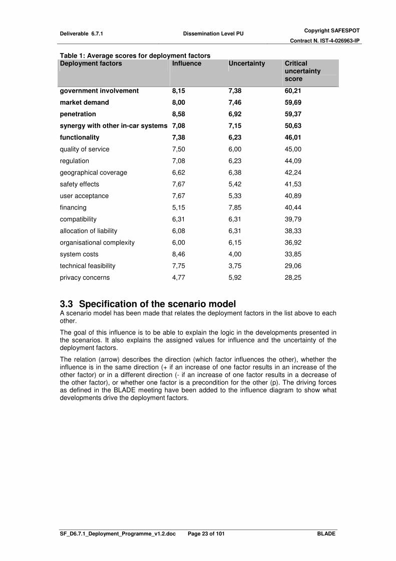
Table 1: Average scores for deployment factors Deployment factors Influence Uncertainty Critical
uncertainty score
government involvement 8,15 7,38 60,21
market demand 8,00 7,46 59,69
penetration 8,58 6,92 59,37
synergy with other in-car systems 7,08 7,15 50,63
functionality 7,38 6,23 46,01
quality of service 7,50 6,00 45,00
regulation 7,08 6,23 44,09
geographical coverage 6,62 6,38 42,24
safety effects 7,67 5,42 41,53
user acceptance 7,67 5,33 40,89
financing 5,15 7,85 40,44
compatibility 6,31 6,31 39,79
allocation of liability 6,08 6,31 38,33
organisational complexity 6,00 6,15 36,92
system costs 8,46 4,00 33,85
technical feasibility 7,75 3,75 29,06
privacy concerns 4,77 5,92 28,25
3.3 Specification of the scenario model A scenario model has been made that relates the deployment factors in the list above to each other.
The goal of this influence is to be able to explain the logic in the developments presented in the scenarios. It also explains the assigned values for influence and the uncertainty of the deployment factors.
The relation (arrow) describes the direction (which factor influences the other), whether the influence is in the same direction (+ if an increase of one factor results in an increase of the other factor) or in a different direction (- if an increase of one factor results in a decrease of the other factor), or whether one factor is a precondition for the other (p). The driving forces as defined in the BLADE meeting have been added to the influence diagram to show what developments drive the deployment factors.

Deliverable 6.7.1 Dissemination Level PU Copyright SAFESPOT
Contract N. IST-4-026963-IP
SF_D6.7.1_Deployment_Programme_v1.2.doc Page 24 of 101 BLADE
Political importance of road safety
Economic growth
Technological developments
Socio-cultural developments
Safety effects
Business model
Penetration rates
Financing
Geographical coverage
Government strategy
Compatibility
Legislation
Quality of service
Market demand
Privacyconcerns
Clear liability
organisational
complexity
System costs
Synergy with other in-car
systems
Functionality
Technical feasibility
+
pp
p
p
p
pp
p
p
p
p p
++
++
+
+
+
++
-
+
-
-
-
-
-
part of
+
+
+
p
p
Figure 3: scenario model
Driving forces (orange) are political importance of road safety, geographical coverage, economic growth and socio-cultural developments. These are external trends that influence the deployment of SAFESPOT but that stakeholders have little or no influence over. Furthermore, they influence deployment of SAFEPOT applications indirectly. The process of scenario development searches for factors that affect deployment directly.
In this scenario model (Figure 3) the market demand and the system costs can be identified as important factors in realising sufficient penetration of equipped vehicles. Important for the system costs is the synergy with other in-car systems. A clear government strategy is a precondition for many other factors.
3.4 Scenario dimensions The third step was to produce basic scenarios based on the scenario dimensions. Three dimensions are defined based on the most influential and most uncertain deployment factors (see Table 1 and Figure 4).
These dimensions are the technical configuration (V2V or V2I), the leading organisations (public lead or private lead) and functional scope of the system (safety functionality only or multi-service). The dimensions are a translation of the five factors that are most influential to cooperative safety systems and uncertain.

Deliverable 6.7.1 Dissemination Level PU Copyright SAFESPOT
Contract N. IST-4-026963-IP
SF_D6.7.1_Deployment_Programme_v1.2.doc Page 25 of 101 BLADE
financing
technical feasibility
compatibilityfunctionalitygeographical coverage
government involvementmarket demand
organisational complexity penetration
privacy concernsquality of service
regulation
safety effects
synergy with other in-car
systems
system costs
user acceptance
4
5
6
7
8
5 6 7 8 9
Un
ce
rta
inty
Influence
Figure 4: Critical uncertainties
The top five critical uncertainties have been translated into 3 scenario dimensions. These
critical uncertainties (see Table 2) are considered as the most relevant deployment factors.
The identification of these scenario dimensions is presented in the following sections. Each translation of critical uncertainties into a scenario dimension is explained below.
Table 2: translation of the deployment factors into scenario dimensions
Critical uncertainties Scenario dimension
government involvement => Public lead vs. private initiative
market demand
functionality => V2V vs. V2I
penetration
synergy with other in-car systems => Dedicated SAFESPOT platform vs. generic in-car platform.
Public lead vs. private initiative
Government involvement and market demand have been combined so they reflect both sides of the scenario dimension public lead vs. private initiative. Government involvement has a large influence on the financing structure, the organisation and also on the functionality of the SAFSPOT system. Taking the lead means that a stakeholder (or group of stakeholders) initiates and enables in-car services to the driver, and largely determines the technical and organisational system configuration. When public stakeholders use their financial and/or regulatory instruments to realise cooperative safety systems, this is considered a public lead. When private stakeholders, e.g. the car industry or nomadic service providers provide cooperative safety applications on a commercial basis without initiation from public stakeholders, this is considered a private lead. Commercial road operators are considered private stakeholders.
V2V vs. V2I
In a V2V configuration the (warning) messages are generated in a smart on-board-unit in the vehicles. A V2V systems configuration could contain simple repeaters that store and broadcast messages.

Deliverable 6.7.1 Dissemination Level PU Copyright SAFESPOT
Contract N. IST-4-026963-IP
SF_D6.7.1_Deployment_Programme_v1.2.doc Page 26 of 101 BLADE
In a V2I configuration the (warning) messages are generated in an intelligent road side infrastructure. This road side infrastructure is likely to be a service centre or an intelligent road side unit equipped with sensors such as a laser scanner.
The factors functionality and penetration have been translated into the scenario dimension V2V (vehicle to vehicle) vs. V2I (vehicle to infrastructure), because the system configuration has a large influence on the deployment. A disadvantage of this dimension is that the actual deployment is likely to be a combination of V2V and V2I communication. The scenarios intend to illustrate likely possible futures. That is why V2V will not be pure V2V but will be a scenario with emphasis on V2V. The same accounts for V2I.
Another possible scenario dimension was the roll out (big bang vs. safe spots). However, the roll out is rather a consequence of the selected functionality then a cause for choosing certain functionality. Therefore functionality (V2V vs. V2I) is chosen as a dimension rather than roll out (big bang vs. safe spots).
Dedicated SAFESPOT platform vs. multi-service platform
Synergy with other systems has been translated into the dimension Dedicated SAFESPOT platform vs. multi-service platform. This is a major factor in the reduction of costs and in the approach of the market and is therefore important in the definition of the scenarios.
A platform facilitates the applications that are provided to the driver. It consists of the on-board-unit, the sensors, the road side infrastructure and the enabled communication technologies.
A SAFESPOT platform provides only SAFESPOT applications. SAFESPOT applications are cooperative time critical safety warning applications (1-5 seconds before the crash) based on short range IEEE 802.11p communication technology.
A multi service platform provides not only safety applications but also e.g. traffic management applications, comfort applications, navigation applications and infotainment applications. Different applications have different communication requirements. Therefore a multi service platform typically supports different communication technologies.
V2IV2V
SAFESPOT platform public lead
private leadmulti-service platform
Figure 5: Scenario dimensions
The three scenario dimensions result in a three dimensional spectrum of deployment scenarios (see Figure 5). The spectrum has eight corners, and thus defines eight scenarios. These eight scenarios are described in a basic form in Annex 2. The names and dimensions are presented in the Table 3.

Deliverable 6.7.1 Dissemination Level PU Copyright SAFESPOT
Contract N. IST-4-026963-IP
SF_D6.7.1_Deployment_Programme_v1.2.doc Page 27 of 101 BLADE
Table 3: spectrum of 8 mini scenarios
configuration lead functionality scenario name
V2V public SAFESPOT "You shall all be safe!"
V2V public multi service "Societal quantity discount"
V2V private SAFESPOT "We want safety!"
V2V private multi service "Technology pushed ITS revolution"
V2I public SAFESPOT "Safety as a public good"
V2I private multi service "Extended traffic management"
V2I public SAFESPOT "Safety for sale in the end"
V2I private multi service "Nomadic storm"
3.5 Selection of the scenarios In the next step three scenarios are selected from the spectrum of eight. Only three scenarios are elaborated in more detail because this is the maximum number of scenarios people can reason with (Sondeijker, 2009).
The selection of the three scenarios is based on three criteria. The criteria for the selection are the likelihood of the scenarios, the distribution of the three scenarios over the spectrum of scenarios, and if the scenarios describe illustrative deployment challenges.
The three selected scenarios are "technology pushed ITS revolution", "safety as a public good" and "extended traffic management” (Figure 6)
V2IV2V
SAFESPOT platform public lead
private leadmulti-service platform
EXTENDED
TRAFFICMANAGEMENTTECHNOLOGY
PUSHED
ITS REVOLUTION
SAFETY AS A
PUBLIC GOOD
Figure 6: Selected scenarios
The selection is done in three steps (see Annex 3: Selection of the scenarios). To reduce the number of combinations of well distributed scenarios with interesting deployment challenges, the first step was to identify the most likely scenarios, which resulted in four most likely scenarios. Then the distribution over the spectrum and the deployment challenges are compared. The scenario of the four most likely scnenarios that was dropped is the “We want safety!” scenario, because it is more likely to follow out of some of the other scnearios. Therefore it is less illustrative to elaborate it as a single scenario. The consequence of selecting three scenarios is a distribution of two scenarios on one side of the each dimension, and one on the other, with the risk of creating a bias. This possible bias in attention was not intensional and did not play any role into the discussion and interpretation of the scenarios.

Deliverable 6.7.1 Dissemination Level PU Copyright SAFESPOT
Contract N. IST-4-026963-IP
SF_D6.7.1_Deployment_Programme_v1.2.doc Page 28 of 101 BLADE
However, the selection is not a mathematical exercise that has one best answer. Several sensible combinations of three likely and interesting scenarios are possible. The selection procedure is a means to structure this (arbitrary) choice and provide insight into the considerations.
3.6 Scenario variables The scenarios are described in terms of 7 scenario variables. Each of the scenarios variables is explained below.
3.6.1 Applications
The applications described in a scenario are typical applications in the context of a scenario. The applications intend to make the scenario more specific and illustrative, they are not an attempt to present a complete set of all applications that are suitable or possible in the context of a scenario.
Some scenarios are about SAFESPOT applications only, others are about both safety applications and non-safety applications.
The following applications are part of the SAFESPOT system part of the scenarios. The applications have been defined by the technical subprojects of the SAFESPOT IP and selected in cooperation with partners of subproject BLADE. For the V2V based system and the V2I based system similar applications have been selected:
V2V – Vehicle based applications:
1. Lateral Collision – LATC: Road intersection safety 2. Road Departure – RODP: Road condition status/Slippery Road warning 3. Longitudinal Collision – LONC: Speed limitation and safe distance
V2I – Infrastructure based applications:
1. Co-operative Intersection Collision Prevention – IRIS: Basic application 2. Hazard and Incident Warning – H&IW: Reduced friction or visibility 3. Speed Alert – SpA: Legal speed limit
The corresponding vehicle and infrastructure based applications feature nearly the same use cases and services. Both the “V2V Road intersection safety” application and the “V2I Co-operative Intersection Collision Prevention Basic” application aim at preventing dangerous situations at intersections. The “V2V Road condition status – Slippery Road Warning” and the “V2I Reduced friction or visibility” application both provide safety relevant information to the driver. Safety relevant information concerning speed is provided by the “V2V Speed limitation and safe distance” application and the “V2I Legal speed limit” application.
A more detailed description of the SAFESPOT BLADE applications and the accident situations in which they are effective can be found in SAFESPOT deliverable 6.5.1 p. 38-45. This section is also added to this document as Annex 5.
The non-safety applications that are mentioned in the scenario are the following:
• Static speed alert: In-car warning when exceeding the legal speed limit (this application could be standalone, using only GPS location data and static maps).
• Navigation with real time traffic information: Information about the traffic conditions are communicated to the OBU and used in the calculation of the navigation advice like TomTom HD traffic (TomTom, 2009).
• Infotainment: Information and entertainment provided in-car, e.g. information about the cheapest gas station or the nearest McDonalds or TV on-demand.
• Cooperative Adaptive Cruise Control (C-ACC): Actively maintains the distance with the predecessor or a preset desired speed. Cooperation with other vehicles in front extends the e-horizon and enables a smoother following of the predecessor then the conventional ACC. C-ACC requires the same technical specification of the Longitudinal Collision – LONC: Safe distance application, and, because it is much more comfortable, is likely to be implemented instead.

Deliverable 6.7.1 Dissemination Level PU Copyright SAFESPOT
Contract N. IST-4-026963-IP
SF_D6.7.1_Deployment_Programme_v1.2.doc Page 29 of 101 BLADE
• Dynamic Road Pricing: Prices for road use on a network scale, where prices are differentiated for time of the day, road type and vehicle type.
• Tolling: Fixed price for a single road
• Gathering floating car data: vehilces collecting information about the traffic conditions and send this to the road operator.
• In-car traffic signs: Traffic signs are presented to the driver in the car on the display of the on-board unit, e.g. speed limits, forbidden turns, one-way streets, etc.
• Green waves with speed recommendation: Intelligent traffic lights adjust their green times to the upcoming traffic. They also communicate a speed advice to vehicles that allows them to make the green light.
• Bus priority: Intelligent traffic lights adjust their green times to give priority to buses.
3.6.2 Technology and system configuration
The table below states that a number of (cooperative safety) applications are considered feasible on a nomadic system, (so without an interface with the motor management system). This is based on the optimal timing of the safety warning (or information message). The ‘optimal timing’ is expressed in the time before the event to which the warning or information is related. E.g. a warning to slow down for congestion can be best presented to the driver about 5-10 seconds before he reaches the end of the queue. This is an estimate based on the link between cooperative safety applications and the differentiation in driver tasks (strategic, tactical and operational) by Demmel, Gruyer, and Rakotonirainy (2009).
Whether an application is feasible on a nomadic system depends on the suitable communication technology, and the required accuracy of location data. An application is considered possible on a nomadic platform (Table 5, column 4) when long range cellular networks are a feasible communication technology and GPS has a sufficient accuracy.
Passive Safety
Active Safety
Cooperative Safety
Cooperative Efficiency
Time
eCall
minutes seconds msec.
PReVENT
APROSYS
SAFESPOT
CVIS
1 sec.
Green area
Au
ton
om
ou
sV
2V
& V
2I
Figure 7: Time-to-Crash SAFESPOT approach (source: SAFESPOT Technical Annex)
The following assumptions are used:
• Warnings that influence the operational driver tasks are best presented to the driver between 0.5 seconds and 2 seconds before the dangerous event. Warnings that influence the tactical tasks are best presented to the driver between 5 seconds and 2 minutes before the dangerous event. Warnings that influence the strategic tasks are best presented minutes to hours or days before the event. These are assumptions by the authors. They are based on the classification of driver tasks and on the goal of the SAFESPOT project to increase the safety margin from the operational driving tasks ( < 1 second) to the tactical driving task ( > 1 second, green area in Figure 7).
• Long range cellular networks will be able to send warning messages with a latency of less then 5 seconds (latency is well below 1 second in today’s Universal Mobile Telecommunications System (UMTS) networks with the necessary capacity available

Deliverable 6.7.1 Dissemination Level PU Copyright SAFESPOT
Contract N. IST-4-026963-IP
SF_D6.7.1_Deployment_Programme_v1.2.doc Page 30 of 101 BLADE
to exchange CoCar CHWs. Source: CoCar Consortium, CoCar Feasibility Study - Technology, Business and Dissemination, Public Report, 2009, p2)
• Assumptions are made on the required accuracy of the location of the vehicles (see Table 5, column 2) and the required sensors for this accuracy (column 3)
Table 4: communication requirements
application
affected
driver task
warming
(time to event) communication technology
BLADE V2V
Lateral Collision (LATC): Road intersection safety operational 0.5 sec - 2 sec short range communication
Road Departure (RODP): Road condition/ Slippery Road tactical 5 sec - 2 min cellullar networks
Longitudinal Collision (LONC): Speed limitation tactical 5 sec - 2 min cellullar networks
Longitudinal Collision (LONC): Speed safe distance operational 0.5 sec - 2 sec short range communication
BLADE V2I
Intelligent Cooperative Intersection Safety (IRIS) operational 0.5 sec - 2 sec short range communication
Hazard and Incident Warn. (H&IW): friction or visibility tactical 5 sec - 2 min cellullar networks
Speed Alert (SpA): Legal speed limit tactical 5 sec - 2 min cellullar networks
other examples
breaking assistant operational none (automatic) short range communication
navigation tactical 5 sec - 2 min cellullar networks
traffic information strategic at planning trip cellullar networks Table 5: applications possible on a nomadic system
application
location
accuracy
required sensor
technology
nomadic solution possible
without can-bus interface
BLADE V2V
Lateral Collision (LATC): Road intersection safety < 5 cm in-vehicle sensors no
Road Departure (RODP): Road condition/ Slippery Road < 5 meters GPS yes
Longitudinal Collision (LONC): Speed limitation < 5 meters GPS yes
Longitudinal Collision (LONC): Speed safe distance < 5 cm in-vehicle sensors no
BLADE V2I
Intelligent Cooperative Intersection Safety (IRIS) < 5 cm in-vehicle sensors no
Hazard and Incident Warn. (H&IW): friction or visibility < 5 meters GPS yes
Speed Alert (SpA): Legal speed limit < 5 meters GPS yes
other examples
breaking assistant < 5 cm in-vehicle sensors no
navigation < 5 meters GPS yes
traffic information < 5 meters GPS yes
3.6.3 Market penetration curve
This section describes how the market penetration curves of the scenarios are estimated. Due to the large number of uncertainties, e.g. about the adoption of the system, a penetration curve is difficult to predict. However, a penetration curve is an essential element in a deployment programme, so a best guess was estimated based on the expected equipment rate of new vehicles and the vehicle age distribution.
To reduce the complexity and the number of assumptions, a ‘normal’ penetration curve was estimated as a reference. The ‘normal’ curve is based on the expert survey estimate of the percentage of new equipped vehicles (SAFESPOT deliverable 6.6.1). In SAFESPOT BLADE work package 6.5 Assessment & Evaluation, these values were combined with the vehicle age distribution within the vehicle fleet used in the project eIMPACT [WILLMINK ET AL. 2008]. The result was the penetration rate of the bundle within the vehicle fleet in 2020. This was extended to a penetration curve until 2050 under the assumption that the percentage of new equipped vehicles increases linear. The ‘normal’ penetration curve is fitted on a typical product life cycle curve showing start-up.
For each deployment scenario, this ‘normal’ curve is shifted left and right for early and later start of the growth period, and stretched for higher or lower deployment speed. The growth period is assumed to start either in 2010, 2015 or 2020. The normal curve is stretched or shrunk for slower or faster deployment. The growth phase is assumed to take 12 to 20 years.
Figure 8 shows the penetration curves of the three deployment scenarios for the percentage of new vehicles that are equipped with the SAFESPOT system.

Deliverable 6.7.1 Dissemination Level PU Copyright SAFESPOT
Contract N. IST-4-026963-IP
SF_D6.7.1_Deployment_Programme_v1.2.doc Page 31 of 101 BLADE
20352010
ne
wve
hic
les e
qu
ippe
d80%
10%
2015
scenarios "Technology pushed ITS revolution"
& "Extended traffic management“deployment speed: 20 years
take off: 2015
2020
scenario
"Safety as a public good" deployment speed: 20 years
take off: 2020
Figure 8: Percentage of new vehicles equipped
The penetration of vehicles in the complete fleet is shown in Figure 9 (for 2 scenarios). The penetration of equipped new vehicles in the whole fleet is about 20 years later than the penetration of equipped new vehicles.
20352010
80%
10%
2015
scenarios "Technology pushed ITS revolution" & "Extended traffic management“deployment speed: 20 years
take off: 2015
2020
equipped vehicles
in fleet
new vehicles equipped
Figure 9: equipped new vehicles and equipped vehicles in fleet
3.6.4 Business model
First of all, the notion of a business model for a safety application is not self evident, because it is not clear how to attribute a value to safety. However, looking at the value chain of actors involved, it becomes obvious that a market value can be generated. Taking into account that SAFESPOT is based on communication between vehicles: a minimum penetration is required for the system to behave well, and to provide a good social benefit. The promise of a large market can be attractive especially for the in- car- electronic industries. This stakeholder is not evident in the business models depicted at this stage (part of the stakeholder group of ‘hardware suppliers’), but it becomes more and more clear that it is fundamental for success.
In the BLADE approach the differences between V2V and V2I are mainly due to the involvement of road operators and public authorities.
The work package 6.6 addressed the business model, which describes the flows of money, services and products. These financial flows are shown in the figure represented in the organisational architecture section (Figure 10: Organisation architecture V2X). The relations between actors represent possible exchange of values to create the final value that is related to the safety information provided by SAFESPOT.

Deliverable 6.7.1 Dissemination Level PU Copyright SAFESPOT
Contract N. IST-4-026963-IP
SF_D6.7.1_Deployment_Programme_v1.2.doc Page 32 of 101 BLADE
A business case, with (estimates of) numbers related to those flows, e.g. prices of the on-board-unit or the service-fees are not estimated.
In the deployment scenarios the flows of money, services and products in the organisational architecture picture are adapted to the individual scenario. For each of the three deployment scenarios described in the next chapter, the organisational architecture figure is presented.
The role of the business models in this phase is relevant in order to allow the potential actors to recognise their role and responsibility, to understand their influence in terms of potential lever to enable the future trends and market. Obviously the companies striving for an immediate gain should be abandoned now in order to transform the business feasibility in a business reality. This process is a path through negotiations and further technological developments, feasibilities studies and consolidation of the relationship as now envisaged.
3.6.5 Organisational architecture
Due to the nature of cooperative systems, which basically requires the operational collaboration of several stakeholders, the deployment path is strongly linked to the organisational structure.
A methodology was developed within SP6 in order to detect the organisational structure that is needed for different implementations of SAFESPOT. This methodology
1,is now adopted to
analyse the different deployment scenarios from an organisational point of view. It was already exploited for the analysis of business models, as it is able to analyze and represent the different levels of complexity related to each individual business model (see D6.6.3),
The organisational architecture investigation methodology is based on the concept of a role. Roles can be regarded as groups of homogeneous functionalities that are needed to run the SAFESPOT system. Roles represent the macro-functionalities included in the general case of a SAFESPOT implementation; for the different bundles of applications in each deployment scenario a set of these functionalities is selected and the resulting roles are then matched to stakeholders. Thirteen roles were identified as necessary for the implementation of a cooperative system like SAFESPOT:
• Public Authority
• Map Provider
• Road Operator
• SAFESPOT host on infrastructure
• SAFESPOT host on vehicle
• Content Provider
• Vehicle hardware & software supplier
• Car Maker
• Infrastructure hardware & software supplier
• Telecom Operator
• Value Added Service Provider (VASP)
• Central Bodies
• Certificators
The detailed description of the roles deriving from this analysis can be found in the SAFESPOT Organisational Architecture work package proceedings (WP6.3).
The representation adopted within this methodology is meant to depict the organisational structure of SAFESPOT by highlighting what are the different roles and what they exchange with each other in order to establish and run the system. Four types of exchanges were identified:
• Operational data (Real-time info/ Periodically updated content)
• Services
• Licences/ Authorizations/ Certificates
• Rules
• Hardware and software products
1 Fully described in D6.3.2

Deliverable 6.7.1 Dissemination Level PU Copyright SAFESPOT
Contract N. IST-4-026963-IP
SF_D6.7.1_Deployment_Programme_v1.2.doc Page 33 of 101 BLADE
A graphical representation was established in order to depict the organisational structure needed in different implementations. In these diagrams all the roles are reported, and each possible exchange, or relationship, envisaged for the SAFESPOT system is drawn.
On the basis of this analysis and formalization it was easier, on one hand, to investigate the implications brought at organisational level by the different possible deployment scenarios and, on the other, to put them in relation with the different driving forces that will influence the future evolution of the SAFESPOT system (time dimension).
In general, in order to understand what influence may be brought by the economic, technological, socio-cultural and political scenario evolution on the organisational aspects of a cooperative system for road safety, it must be considered that the union of all the roles forms the whole set of responsibilities to be assigned to the actors in order to satisfy the functional requirements defined in the logical architecture, or, in practical terms, in order to make the system work. As a consequence, the assumption that SAFESPOT maintains the same functional structure in any possible future scenario, means that this role set will be an invariant. This implies that in no scenario changes will happen causing the modification or elimination of some role, nor the introduction of new ones.
What might actually influence the system at an organisational level, is instead which actual type of organization will play each single role in different scenarios. In a scenario where a certain driving force, typically the economic growth or an increased political importance for road safety, would boost a higher geographical coverage of the SAFESPOT system, for instance, this could trigger some economy of scale inducing some actor to extend his responsibility area, taking charge of extra roles
Another element that may change at an organisational level in the future regards how the different roles interface to each other, in case the interfaces regard the data exchange. This aspect is mainly connected to the technological developments driving force, given that in the future the data exchanges will be influenced by the available technologies.
Here below the global scheme of the SAFESPOT organisational architecture is reported. This diagram depicts the widest possible scenario, i.e. the general case where all the roles and relationships are present. In the next chapter the organisational diagrams are reported for each deployment scenario; each scenario diagram is a different subset of the global scheme.
A brief description of the organisational implications follows for each scenario, including examples on the stakeholders that may play the different roles in a real world implementation.

Deliverable 6.7.1 Dissemination Level PU Copyright SAFESPOT
Contract N. IST-4-026963-IP
SF_D6.7.1_Deployment_Programme_v1.2.doc Page 34 of 101 BLADE
SAFESPOT Integrated Project <Progress & Workshop meeting BLADE >29th October 2009, Cologne1
Map
Provider
Telecom
Operator
Driver Central
Bodies
legal
framework
value added
service,
customer
support/
maintenance
event msgs
(SP2),
Road
Operator
safety rel.
content
alerts
(SP4)
alerts
(SP5)
authenticationContent
Provider
alerts
(sp5)
Type of exchange:1) Operational data
2) Services3) Licences/ Authorizations/
Certificates4) Rules5) Hw and sw products
event msgs
(SP1),
beacons,
Veh hw&sw
supplier
Infr. hw&sw
supplier
Certificator
SF-Host on
Vehicle
maintenance
roadside devices
data models
& interfaces
RSU + BSA
event msgs
(SP1),
beacons,
LDM structure
LDM structure
VASPvalue added
service
V2X
OBU +
BSA
static map
layer
road geometry
updates
certificates
content for value
added service
long range
connectivity
OBU +
BSA
Car Maker
vehicle data
grants for
communication
channels
Public
Authority
SF-Host on
Infrastructure
safety related
content
V2V
I2VV2I
Figure 10: Organisation architecture V2X
3.6.6 Societal cost and benefits
The socio-economic assessment of the V2V based and the V2I based SAFESPOT systems shows an aggregated value for the benefits of the systems in the field of safety, traffic flow efficiency and emission reduction (SAFESPOT deliverable 6.5.1). By comparing these benefits with the costs of the safety systems of equipping the vehicle fleet and the infrastructure the efficiency of the systems is shown. The cost-benefit ratios in SAFESPOT-BLADE are derived for different penetration rates of the systems. In general, the economic viability of the systems increases with the size of the market.
The information generated by the socio-economic assessment gives an idea of the expected economic potential of the systems. In combination with the derived safety and traffic impacts the cost-benefit results can provide the foundation for actions of public stakeholders in the field of cooperative safety system to increase the deployment speed or to come to an earlier take off of the systems. Possible actions of public authorities to speed up market introduction, for example, are tax subsidies for safety systems in vehicles, supporting the development of standards for design of the safety systems or making the systems mandatory.
The brake even period calculated for each scenario is based on the socio-economic assesment performed in SAFESPOT BLADE work package 6.5 Assessment & Evaluation. The values of the BCR (benefit cost radio) and pay-back period are based on penetration rate (see also section 3.6.3 Market penetration curve). These penetration rates were combined with the vehicle age distribution within the vehicle fleet used in the project eIMPACT [WILLMINK ET AL. 2008]. The result was the penetration rate of the bundle within the vehicle fleet in 2020. This was extended to a penetration curve until 2050 under the assumption that

Deliverable 6.7.1 Dissemination Level PU Copyright SAFESPOT
Contract N. IST-4-026963-IP
SF_D6.7.1_Deployment_Programme_v1.2.doc Page 35 of 101 BLADE
the percentage of new equipped vehicles increases linear. The price levels from the cost benefit analysis are used (year 2020). The pay-back period is still an indication for the economic benefit, but not a hard number.
Benefit-cost results can also be of interest for investment decisions of private stakeholders e.g. road operators, OEMs, and automotive suppliers. A high benefit-cost ratio provides some information about the attractiveness of the system for the users and therefore willingness to pay. An expected high benefit of the safety systems can be an indicator of the market potential of the systems and thus, for example, stimulate costly awareness campaigns and participating in FOTs to get a more accurate knowledge of the impacts of the systems.
Altogether, results of socio-economic assessment can provide a foundation and thus incentives for stakeholders to take actions to change the deployment path of safety systems (time of take off, deployment speed). Which actions are best suited and which roles are taken by public and private stakeholders will also depend on the relevant business model.
3.6.7 Legal framework
32Y ReviewTurijn, 15 May 2008
Legal framework/regulatory options
TaxTax incentivesincentives, , standardstandardvehiclevehicle equipement, equipement,
mandatedmandated useuse
MoUMoUInsurance Insurance incentivesincentives6) 6) GeographicGeographic coveragecoverageand and fleetfleet penetrationpenetration
………………..
Model Model contractscontracts
SelfSelf regulationregulation
FormalFormal standardisationstandardisation, , Code of Code of PracticePractice
FormalFormal standardisationstandardisation, ,
certificationcertification
FormalFormal standardisationstandardisation
MoUMoU, , operationaloperational
involvementinvolvement of the public of the public
sector (e.g. sector (e.g. safetysafety center?)center?)
b) Public/Privateb) Public/Private
…………....…………………………..
ModifyModify torttort, contract and/, contract and/oror
insuranceinsurance lawlaw (e.g. (e.g.
channellingchannelling))
ContractualContractual agreementsagreements
betweenbetween partiesparties in the in the chainchain of of
productionproduction and and operationoperation
7) 7) AllocationAllocation of of risksrisks
Sector Sector specificspecific regulationregulationContractualContractual agreementsagreements5) 5) StorageStorage and and useuse of of data data
SafetySafety standardsstandards and type and type approvalapproval procedures procedures
ContractualContractual agreementsagreements4) System performance 4) System performance requirementsrequirements
StatutoryStatutory data and service data and service
qualityquality requirementsrequirementsContractualContractual agreementsagreements
betweenbetween public public
authoritiesauthorities,content providers, ,content providers,
and service providersand service providers
3) Data and service 3) Data and service
qualityquality requirementsrequirements
StatutoryStatutory data data formatformat
requirementsrequirementsDe De factofacto standardisationstandardisation2) 2) HarmonisationHarmonisation of data of data
and exchange and exchange formatsformats
StatutoryStatutory dutiesduties forfor
public/private public/private actorsactors to to
gathergather and provide data and provide data
ContractualContractual agreementsagreements
betweenbetween public public authoritiesauthorities, ,
content providers, and service content providers, and service
providers. providers.
1) 1) acquisitionacquisition and and
processing of dataprocessing of data
(e.g. speed (e.g. speed limitslimits))
c) Publicc) Publica) Private a) Private
This table gives an indication of the type of legal arrangements, conditions and requirements that may be involved in the deployment of Safespot. It illustrates what type of legal arrangements or legal instruments may constitute the legal framework for cooperative systems. In a pure private scenario (column a) the relationships between the different actors are primarily governed by voluntary, private law based agreements. In a (pure) public driven scenario the deployment is forced by government implying an elaborated legal framework (as would be required for the introduction of OBU/GPS-based electronic toll collection) Between pure private and a pure public driven deployment of cooperative systems, there is a variety of mixed public/private deployment paths and accompanying legal framework landscapes. Furthermore legal landscapes are, next to the classical private and public law instruments, more and more ‘infiltrated’ by law and rulemaking of a hybrid nature (see column b). A institutional/legal framework could also include the following:
• Setting up the required administrative structures (public, public/private or private) to establish the required organisational setting for one or more specific applications (through regulation or, possibly, contract)
• Harmonisation of data and exchange formats, through contracts or regulation
• Setting requirements on data and service quality, through contract or regulation)
Deliverable 6.7.1 Dissemination Level PU Copyright SAFESPOT
Contract N. IST-4-026963-IP
SF_D6.7.1_Deployment_Programme_v1.2.doc Page 36 of 101 BLADE
• Setting performance requirements for system hardware – probably through regulation
• Mandating contractual arrangements between parties in the chain of production and operation to crystallise their liability exposures to each other.
• Creating a compensation/restoration fund, allowing for swift compensation and/or system restoration, leaving the final allocation of liability/responsibility to mechanisms of subrogation and redress.
• Modifying tort (and insurance) law (e.g. channelling responsibility to one party in the first place, such as the driver of the probe vehicle).
• Modifyinig traffic laws - vehicle standards, traffic rules, rules on driving licences, including training in the use of ITS products/services).

Deliverable 6.7.1 Dissemination Level PU Copyright SAFESPOT
Contract N. IST-4-026963-IP
SF_D6.7.1_Deployment_Programme_v1.2.doc Page 37 of 101 BLADE
4 Scenarios for deployment (Results) This chapter presents the three scenarios that have been developed. The scenarios are called ‘Technology pushed ITS revolution’, ‘Safety as a public good’ and ‘Extended traffic management’ (the five scenarios representing the other corners of the ‘scenario space’ are described in a basic form in Annex 2 Basic scenarios). Each scenario consists of two main elements. This first element is the image of the future, which describes the situation when the SAFESPOT system is fully deployed, and the majority of vehicles are equipped. The second main element is the deployment path, which describes the milestones that lead to the future situation. The scenarios are described in terms of the scenario variables (see chapter 3). The future situation is described in terms of the scenario variables, Applications, Technology and system configuration, Standardisation, Business model, Organisational architecture and Societal cost and benefits. The deployment path is described in terms of milestones, a storyline and the scenario variable Market penetration. The scenario development was an iteration between the future situation and the deployment path (see section Steps in the scenario analysis).
4.1 Scenario: Technology pushed ITS revolution This scenario represents the lower left corner of the scenario space (see Figure 11) and starts from the assumptions that private stakeholders take the lead, applications based vehicle to vehicle communication, and only a generic platform providing different kinds of applications.
TECHNOLOGY PUSHEDITS REVOLUTION
V2IV2V
SAFESPOT platform public lead
private leadgeneric platform
Figure 11: Technology pushed ITS revolution in scenario space Distinctive for this scenario are a factory fit OBU with short and long range communication, a wide range of applications being: Lateral Collision (LATC): Road intersection safety, Road Departure (RODP): Road condition/ Slippery Road, Longitudinal Collision (LONC): safe distance and speed limit, navigation with real time traffic information. This is a fully private scenario with no government funding.
4.1.1 Deployment path
The deployment path is described in terms of milestones, a storyline and the scenario variable Market penetration.
Milestones
� PND industry offer, next to real-time traffic information and infotainment, speed alert (SpA) and Local Hazard Warning, based (RODP) and will try to offer any possible application on long range communication (e.g. GPRS) (Proof of concept phase)
� The car industry offer standalone longitudinal collision warning. (Proof of concept phase) � V2V communication standards (including type of warnings and identification of dangerous
situations) are agreed between car industry � Car manufacturers, suppliers and nomadic service providers develop and built in OBU
with that supports both short and long range communication. (FOT)

Deliverable 6.7.1 Dissemination Level PU Copyright SAFESPOT
Contract N. IST-4-026963-IP
SF_D6.7.1_Deployment_Programme_v1.2.doc Page 38 of 101 BLADE
� Additional applications become available on this platform. � (Active safety applications such as ACC and Active Braking Assistance are a logical
addition to the applications mentioned above, but they are outside the scope of the SAFESPOT project)
Penetration curve The market penetration curve shows the new equipped vehicles. For each scenario the moment of take off and the deployment speed are estimated. The take off for this scenario is estimated as early as 2015, because the PND industry already has the available platform to provide cooperative safety functionality. Although the speed alert application and the local hazard warning could deploy very fast (based on the existing platform), other more time critical applications like intersection safety and longitudinal collision warning require more time and will need to be factory fit. Therefore the deployment speed is expected to be 20 years, which is based on the ‘medium fast’ market penetration of new vehicles.
Figure 12 penetration curve ‘Technology pushed ITS revolution’
Storyline Nomadic service providers (e.g. navigation providers like TomTom and smart phone providers NOKIA
2) already offer traffic information, (static) speed alert, and infotainment applications
(games, information about the cheapest gas station or the nearest McDonalds). Increasingly the traditional navigation providers will offer a wider range of applications on a more and more intelligent in-car service platform. Connecting floating car data enables the nomadic devices to know where traffic queues start, where dangerous curves, icy parts or risky intersections are. The nomadic service providers provide dynamic speed alert (SpA) and local hazard warning (RODP). A more accurate positioning (GPS) and faster communication is required, to move towards more time critical warning systems, such as intersection safety (IRIS) and longitudinal collision warning (LONC). However, these applications require cooperation with the car manufacturers. Car industry has gained experience in standalone warning systems based on in-vehicle sensors (such as radar). Car industry and nomadic service industry combine their strengths and develop OBUs integrated in the dashboard of the car. This allows a wide range of safety warning applications and comfort applications (and for automatic systems (e.g. C-ACC and emergency braking, but that is outside the scope of the SAFESPOT project).
4.1.2 Future situation
The future situation is described in terms of the scenario variables, Applications, Technology and system configuration, Standardisation, Business model, Organisational architecture and Societal cost and benefits. The deployment path is described in terms milestones, a storyline and the scenario variable Market penetration.
2 http://maps.nokia.com/ovi-services-and-apps/ovi-maps/downloads#/default/
deployment speed: 20 years
take off: 2015
20352010
equip
pe
d n
ew
vehic
les 80%
10%
2015

Deliverable 6.7.1 Dissemination Level PU Copyright SAFESPOT
Contract N. IST-4-026963-IP
SF_D6.7.1_Deployment_Programme_v1.2.doc Page 39 of 101 BLADE
System architecture and functionality The platform consists of intelligent on-board units, using both long range and short range communication, which support multiple applications ranging from Lateral Collision (LATC): Road intersection safety, Road Departure (RODP): Road condition/ Slippery Road, Longitudinal Collision (LONC): safe distance and speed limit, navigation with real time traffic information and infotainment applications.
Figure 13: System architecture with short and long range communication (CVIS, 2009) Organisational Architecture In this deployment scenario two roles are missing compared to the complete V2X case, due to the fact that this is a V2V scenario, therefore no road-based applications are envisaged: these are the “SF-Host on Infrastructure” and the “Infr. hw&sw supplier”. The “Road Operator” role is limited to its activity of providing continuous updates of the road geometry to the “Map Provider”. The resulting organisational structure is simplified due to the fact that many relationships are linked to these roles. The “SF-Host on Vehicle” is played by the same company as the Car Maker (Renault, in the example), given that, in the final evolution of this scenario the Car Maker will take the lead introducing more advanced, time-critical applications (in the early phase PND manufacturers would play this role with non time-critical applications).

Deliverable 6.7.1 Dissemination Level PU Copyright SAFESPOT
Contract N. IST-4-026963-IP
SF_D6.7.1_Deployment_Programme_v1.2.doc Page 40 of 101 BLADE
1
V2I
V2V
Public
Authority
Map
Provider
Telecom
Operator
Driver Central
Bodies
legal
framework
value added
service, customersupport/
maintenance
Road
Operator
alerts(SP4)
ContentProvider
Type of exchange:1) Operational data
a. Frequently updated contentb. Periodically updated content
2) Services
3) Licences/ Authorizations/ Certificates4) Rules5) Hw and sw products
grants forcommunication
channels
Veh hw&swsupplier
Infr. hw&swsupplier
Certificator
SF-Host on
Infrastructure
SF-Host onVehicle
data models& interfaces
authentication
event msgs
(SP1), beacons,
LDM structure
VASPvalue addedservice
safety and information
related content
OBU +
BSA
static
map layer
road geometryupdates
certificates
content for valueadded service
long rangeconnectivity
OBU + BSA
Technology pushed ITS revolution (final situation)
Magneti Marelli
electronic systems
Tom Tom
Ministère de
l'Equipement des
Transports et du
Logement
TNO, TUV
TomTom
Vodafone
Renault
Car Maker
vehicle data
Renault
TomTom
ETSI, ISO,
car2car, CEN
STAKEHOLDERS ARE EXAMPLES FOR THIS SCENARIOCofiroute
Figure 14: Organisational architecture 'Technology pushed ITS revolutions'
Business model Car makers and their suppliers envisage in the V2V technology the possibility to offer not only the safety but also the travel comfort. All together, under the pressure of a more democratic approach to the safety (it’s not a matter of segment) collaborate to have a mass volume in order to reduce market cost. � Functionality: The functionalities provided are safety functions and navigation applications
+ some personalized applications (see also above). � Financing: Is this scenario, the system will be financed completely by the end-user. � Price policy: The OBU with basic safety and navigation functionality is offered with a price
policy that aims for a fast market introduction in all vehicle price segments (affordable price) which reduces the time to for the industries to earn their investment money back. For additional personalised applications an additional monthly fee is paid.
This business model is (based on the business model) described in more detail in D6.6.3 (business model 9) Socio-economic impact The pay-back period is a measure for the socio-economic impact. However the socio economic impact represented by the pay-back period is not a calculation of the exact of the exact cooperative system presented in this scenario. The calculation is based on the vehicle to vehicle based longitudinal safety warning application only (LONC).

Deliverable 6.7.1 Dissemination Level PU Copyright SAFESPOT
Contract N. IST-4-026963-IP
SF_D6.7.1_Deployment_Programme_v1.2.doc Page 41 of 101 BLADE
The presented pay-back period calculation is based on the methodology developed in SAFESPOT WP 6.5 (Deliverable 6.5.1 Socio economic impact assesment) with the following additional assumptions to extend the time scale. The penetration was extended to a penetration curve until 2050 under the assumption that the percentage of new equipped vehicles increases linear. The price levels from the cost benefit analysis are used (year 2020). The BCR (Benefit Cost Ratio) of the V2V based longitudinal safety warning is > 1 from year of introduction. The pay-back period is still an indication for the economic benefit, but due to the assumptions it is not a hard and absolute number. The actual socio economic impact is expected to be more positive due to the additional effects of the non-safety systems. Legal setting This is a ‘private lead’ scenario. There is no government intervention to actively steer the deployment of cooperative systems. The institutional/legal landscape will be dominated by column a) and b). Although there is no public lead, this does not mean that there will be no government intervention at all. At least authorities will prevent that cooperative systems may impair traffic safety, for example by setting some safety and performance requirements (and accompanying test- and certification procedures) for such systems. Furthermore, authorities may choose to support the rapid deployment of Safespot systems for example by allocating the required frequencies, supporting technical harmonisation, providing relevant data to the industry (e.g. speed limits) or providing tax incentives.
4.1.3 Deployment challenges
Reach critical mass In this scenario the existing penetration of nomadic devices and the existing GSM/UMTS infrastructure is used as a launching pad for dedicated in car systems. Several safety warnings can be provided through this existing platform, but for time critical safety applications (warning and automatic), the challenge for car manufacturers and PND providers is realise the interface between the vehicle and the safety application. Step by step deployment path The large step in this scenario is to realise the interface between the vehicle and the application. This large step could be broken down into smaller steps like defining a standard for interfacing with the car data, and a standard for interfacing with nomadic devices. Realise a European market Dealing with limited bandwidth and priority for safety messages in a European way might be a challenging barrier for PND service providers. Business case for all stakeholders Car makers will realise that in-car services contribute to their core business of selling cars. A challenge for them will be to choose between a business case for outsourcing in-car services to a PND provider or a business case for developing in-car services in-house. Cooperation between the stakeholders Cooperation between PND providers and car makers, and between car makers and their suppliers will be a challenge.
4.1.4 Recommended actions
Road authorities and road operators The role of the road authorities and road operators is to provide a minimum service level for safety, throughput and emissions. In this private scenario this means monitoring and e.g. enforcing dynamic speed limits. 1.1 buy floating car data for traffic management 1.2 set minimum quality requirements to the provided services Car manufacturers and suppliers The role of the car manufacturers must change from a seller to a service provider. This requires a new approach (e.g. training dealers) and new knowledge (e.g. about telecommunication). To what extent a car manufacturer will do these things himself or outsource this.

Deliverable 6.7.1 Dissemination Level PU Copyright SAFESPOT
Contract N. IST-4-026963-IP
SF_D6.7.1_Deployment_Programme_v1.2.doc Page 42 of 101 BLADE
1.3 Develop an industry standard for the interface to access vehicle data from the proprietary vehicle network, to facilitate an in-car service platform
1.4 Integrate nomadic services into vehicles through a standardised interface with the vehicle (industry standard)
Nomadic service providers Use the existing penetration of nomadic navigation devices to extend to a cooperative platform based on long range cellular communication technology (e.g. GPRS/UMTS) 1.5 Develop new (safety and other) applications on the existing long range cellular
communication based platform 1.6 Develop a business model that deals with the cost of data communication on long
range cellular networks for in-vehicle applications 1.7 Integrate nomadic services into vehicles through a standardised interface with the
vehicle (industry standard)

Deliverable 6.7.1 Dissemination Level PU Copyright SAFESPOT
Contract N. IST-4-026963-IP
SF_D6.7.1_Deployment_Programme_v1.2.doc Page 43 of 101 BLADE
4.2 Scenario: Safety as a public good This scenario represents the lower left corner of the scenario space (see Figure 15) and starts from the assumptions that public stakeholders take the lead, applications based vehicles to infrastructure communication, and only SAFESPOT applications.
V2IV2V
SAFESPOT platform public lead
private leadgeneric platform
SAFETY AS A PUBLIC GOOD
Figure 15: Safety as a public good in the scenario space
Distinctive for this scenario, besides the scenario dimension are that the platform provide only short range safety (SAFESPOT) applications. The applications in this scenario are Intelligent Cooperative Intersection Safety (IRIS), Hazard and Incident Warn. (H&IW): friction or visibility, Speed Alert (SpA): Legal speed limit. The OBU’s are subsidized by the national governments.
4.2.1 Deployment path
The deployment path is described in terms of milestones, a storyline and the scenario variable Market penetration. Milestones � FOTs with the I2V safety systems Intelligent Cooperative Intersection Safety (IRIS),
Hazard and Incident Warn. (H&IW): friction or visibility, Speed Alert (SpA): Legal speed limit.
� National, regional and local road operators invest in intelligent road side infrastructure. � Car-manufacturers start developing other functionality on the short-range communication
platform (C-ACC, local hazard warning and intersection safety) � The insurance companies make these systems financially very attractive because they
reduce the insurance premium Penetration curve The market penetration curve shows the new equipped vehicles. For each scenario the moment of take off and the deployment speed are estimated. The take off for this scenario is estimated as in 2020, which is 5 years later then the ‘normal’ curve as expected in the expert survey (deliverable 6.6.1) (see the shift compared to the ‘normal’ (black) curve in Figure 16. The deployment speed is expected to be 20 years, which is based on the ‘medium fast’ market penetration of new vehicles. Although the price of the OBU is subsidized, car-users still need to buy the system.

Deliverable 6.7.1 Dissemination Level PU Copyright SAFESPOT
Contract N. IST-4-026963-IP
SF_D6.7.1_Deployment_Programme_v1.2.doc Page 44 of 101 BLADE
Figure 16: Penetration curve 'Safety as a public good' (red) and 'normal' (black)
Storyline Due to increasingly busy roads, an aging population that wants to stay mobile, road safety becomes a political priority. FOTs with I2V safety systems such as intelligent Speed Alert (SpA) with haptic gas pedal show impressive safety effects and are political successes. National and local road authorities throughout Europe start doing FOTs with Intelligent Cooperative Intersection Safety (IRIS), Hazard and Incident Warn. (H&IW): friction or visibility, Speed Alert (SpA). These FOTs provide a clear picture on which ‘black spots’ (which parts of the infrastructure) are worth equipping with short range communication equipment from a societal cost benefit point of view. Car-manufacturers take the opportunity to offer their customers built-in OBUs that present the infrastructure warnings to the drivers and also provide information about dangerous situations based on the vehicles’ sensors. The cost for the in-car equipment is subsidised by national governments and a reduction on the insurance premium.
4.2.2 Future situation
The future situation is described in terms of the scenario variables, Applications, Technology and system configuration, Standardisation, Business model, Organisational architecture and Societal cost and benefits. The deployment path is described in terms of milestones, a storyline and the scenario variable Market penetration. System architecture and functionality The platform consists of short range road side communication infrastructure and simple on-board units (both built in and nomadic) equipped with short range communication which bring the centralized services into the vehicles. Applications that are be provided are Speed Alert (SpA), Intersection Safety (IRIS), Hazard and Incident Warning (H&IW)
Organisational Architecture
Long Range communication is not included in this scenario, therefore the “Telecom Operator” role is not present. Moreover no value added services are included, hence nor the “VASP”
deployment speed: 20 years
take off: 2020
20352010
equip
pe
d n
ew
vehic
les 80%
10%
2015

Deliverable 6.7.1 Dissemination Level PU Copyright SAFESPOT
Contract N. IST-4-026963-IP
SF_D6.7.1_Deployment_Programme_v1.2.doc Page 45 of 101 BLADE
role is needed. All the rest of the organisational structure corresponds to the general case, including all the V2I part; this makes this scenario more challenging than the previous one from an organisational point of view. The “SF-Host on Vehicle” is played, in the example, by car manufacturing companies; this is the case where the on-board system is provided as a factory-fit solution; however, in case of aftermarket solution (nomadic device), it can be played also by PND manufacturers. The “SF-Host on Infrastructure” is indicated in the example as the same company as the Road Operator; however this may also be a separated (subcontracting) company managing traffic telematics on behalf of the Road Operator.
1
V2II2V
Map Provider
Telecom Operator
Driver Central
Bodies
legal
framework
customer
support/ maintenance
event msgs (SP2),
Road Operator
safety rel. content
alerts (SP4)
alerts (SP5)
authenticationContent Provider
alerts
(sp5)
Type of exchange:1) Operational data
a. Frequently updated contentb. Periodically updated content
2) Services
3) Licences/ Authorizations/ Certificates4) Rules5) Hw and sw products
authentication
event msgs
(SP1), beacons,
Veh hw&sw supplier
Infr. hw&sw supplier
Certificator
SF-Host onInfrastructure
SF-Host onVehicle
maintenance
roadside devices
data models
& interfaces
RSU +
BSA
authentication
LDM structure
LDM structure
VASP
safety related
content
Safety as a public good (final situation)
OBU +
BSA
static map layer
road geometry updates
certificates
OBU + BSA
Bosch
Tele Atlas
Rijkswaterstaat
Ministery van
Verkeer en
Waterstaat
TNO, TUV
Rijkswaterstaat
Rijkswaterstaat
Peek
ETSI, ISO,
car2car, CEN
Car Maker
vehicle data
Daimler, FIAT,
Renault,Volvo
Daimler, FIAT,
Renault,Volvo
STAKEHOLDERS ARE EXAMPLES FOR THIS SCENARIO
grants for communication
channels
Public Authority
Figure 17: Organisation architecture 'Safety as a public good'
Business model Public authorities decide to increase safety. The SAFESPOT technology is adopted with the design to reach in a medium time a good penetration of the circulating vehicles so that the scenario can become fully cooperative with advantages in terms of increased social benefit with less expense adopting the recognized standard. � Equipping the complete road network with a short range road side communication
infrastructure is too expensive. Only parts of the road network will be equipped for which the societal benefits are highest.
� Financing: The infrastructure is financed by road authorities. The OBU is subsidized by national governments or by insurance companies.
� Pricing policy: The OBU is distributed at very low cost “political price”.

Deliverable 6.7.1 Dissemination Level PU Copyright SAFESPOT
Contract N. IST-4-026963-IP
SF_D6.7.1_Deployment_Programme_v1.2.doc Page 46 of 101 BLADE
This business model is (based on the business model) described in more detail in D6.6.3 (business model 4) Socio-economic impact The pay-back period is a measure for the socio-economic impact. However the socio economic impact represented by the pay-back period is not a calculation of the exact of the exact cooperative system presented in this scenario. The calculation is based on the vehicle to bundle functionally, containing Intelligent Cooperative Intersection Safety (IRIS), Hazard and Incident Warn. (H&IW), Speed Alert (SpA): Legal speed limit (as described in d6.5.1). The presented pay-back period calculation is based on the methodology developed in SAFESPOT WP 6.5 (Deliverable 6.5.1 Socio economic impact assesment) with the following additional assumptions to extend the time scale. The penetration was extended to a penetration curve until 2050 under the assumption that the percentage of new equipped vehicles increases linear. The price levels from the cost benefit analysis are used (year 2020). The BCR (Benefit Cost Ratio) period of the V2V based longitudinal safety warning is > 1 from year 2042. This long pay-back period is due to the enormous cost of equipping the infrastructure. The actual socio economic impact is expected to be more positive due when only ‘black spots’ are equipped. The pay-back period is still an indication for the economic benefit, but due to the assumptions it is not a hard and absolute number. Legal setting The infrastructural involvement that characterizes this scenario affects the institutional and legal conditions and requirements for deployment. One important issue is the technical harmonisation of road side equipment and coordinated deployment of services. Furthermore, legal interventions (see column c) may be required to enhance penetration levels and to ensure minimum levels of services. For example, OBU’s may become mandatory for all new vehicles and/or road authorities may be under a legal obligation to equip their roads and to provide Safespot relevant data to services providers.
4.2.3 Deployment challenges
Reach critical mass In this scenario the problem of reaching critical mass is tackled by the infrastructure. Even with a limited number of equipped vehicles (<5%) the system has added value if the infrastructure provides warning messages Step by step deployment path The large step in this scenario is to realise an infrastructure with sufficient coverage. The challenge is to provide government with a step by step plan to enrol an infrastructure, and break up the decisions for these huge government investments in steps. One step is to realise already a part of the infrastructure and provide arguments for more investments could be the realisation of a FOT. However, realising a FOT with cooperative systems is a huge challenge. Realise a European market A European market is a challenge for governments in this scenario. It is a challenge because the business case for the car industry to invest in the in-car part of this dedicated safety system is very thin. Without the prospect of a large European market, the car industry may not invest and huge subsidies might be needed to get the in-car investments going. This is important for governments to realise when they invest in an expensive road side infrastructure. Business case for all stakeholders This is the biggest challenge for this scenario. Since this scenario describes a systems dedicated only to safety, and people might not be willing to pay for that, the business case for the car industry is a challenge. Subsidies or other instruments to guarantee return on investment by (national or EC) governments might be necessary to ensure a solid business case. To ensure a positive business case for road authorities, FOTs might be a good means. They might give insight in which part of infrastructure should be equipped for an optimal societal cost benefit ration.

Deliverable 6.7.1 Dissemination Level PU Copyright SAFESPOT
Contract N. IST-4-026963-IP
SF_D6.7.1_Deployment_Programme_v1.2.doc Page 47 of 101 BLADE
Cooperation between the stakeholders Cooperation between national governments is a challenge because of the different interest of these countries in their national car industries. This could result in the refusal of some countries to subsidise OBUs (and thus the car industry) and therefore do not invest in the road side infrastructure. This could mean that a European market is not realised.
4.2.4 Recommended actions
Road authorities and road operators 2.1 Invest in field operational tests (with support of policy makers) in order to obtain arguments for public investments. 2.2 Invest in road side infrastructure on ‘black spots’ and in OBU’s on a European scale to ensure a European market. The recommendation to invest seems contradictory to the long payback period estimated in the societal cost benefit analysis. However, the cost benefit analysis was based on costs for fully equipping the infrastructure. The concept of ‘black spots’ could reduce this. Public private partnerships could be an additional solution to reduce the investment. Car manufacturers and suppliers 2.3 Car manufacturers and suppliers should develop industry standards for communication and on the application level. 2.4 Car-manufacturers should developing other functionality on the short-range communication platform (C-ACC, local hazard warning and intersection safety) Insurance companies 2.5 Insurance companies could stimulate the market for in-car systems by offering reduction on the insurance premium. Nomadic service providers Nomadic service providers have no role in this scenario.

Deliverable 6.7.1 Dissemination Level PU Copyright SAFESPOT
Contract N. IST-4-026963-IP
SF_D6.7.1_Deployment_Programme_v1.2.doc Page 48 of 101 BLADE
4.3 Scenario Extended traffic management This scenario represents the lower left corner of the scenario space (see Figure 18) and starts from the assumptions that public stakeholders take the lead, applications based vehicles to infrastructure communication, and only a generic platform providing different kinds of applications.
EXTENDED TRAFFIC
MANAGEMENT
V2IV2V
SAFESPOT platform public lead
private leadgeneric platform
Figure 18: Extended traffic management in the scenario space Distinctive for this scenario, besides the scenario dimension are that the system is a nomadic system (aftermarket). The applications are dynamic speed alert (SpA), Local Hazard Warnings (H&IW), eCall and navigation with real time traffic information and dynamic road pricing.
4.3.1 Deployment path
The deployment path is described in terms of milestones, a storyline and the scenario variable Market penetration. Milestones � To stay in control of traffic management, road authorities invest in intelligent road side
systems to provide traffic information, speed alert (SpA), Local Hazard Warnings (H&IW), traffic safety (IRIS), recommended speed for green light, and road pricing,
� Providers of road side infrastructure, navigation providers and car manufacturers all start providing (nomadic or factory fit) on-board units, to bring these applications to the road users.
� Alliances between the stakeholders will enable the integration of information applications, (active) safety applications and comfort applications into one in-car system with on interface.
Penetration curve The market penetration curve shows the new equipped vehicles. For each scenario the moment of take off and the deployment speed are estimated. The take off for this scenario is estimated as early as 2015, because the infrastructure is available from 2015, a minimum service level is provided. This stimulates the early market-introduction for in-car systems. Despite the potentially fast deployment due to the aftermarket possibility, the expected deployment speed is 20 years which is based on the ‘medium fast’ market penetration of new vehicles. This is because the functionality of the systems depends on the amount of infrastructure, which will take a long while to be rolled out.

Deliverable 6.7.1 Dissemination Level PU Copyright SAFESPOT
Contract N. IST-4-026963-IP
SF_D6.7.1_Deployment_Programme_v1.2.doc Page 49 of 101 BLADE
Figure 19: market penetration curve 'Extended traffic management' scenario
Storyline Road authorities try to meet their traffic management responsibilities. Therefore they need to stay in control of the traffic flows. They need to deal with the increasing network management power of the large navigation system providers with huge markets shares. In the battle for access to the driver they provide, speed alert and in-car traffic signs, through an intelligent road-side communication infrastructure and regulate the in-car platform functionalities. This regulation could be either legally enforced by the policy makers or by stimulating certified OBUs by giving them a lower kilometer price in case of road pricing. Although the philosophy is to leave as much as possible to the market, some things need to be regulated, e.g. the price for using the road (dynamics road pricing) and the dynamic speed limit. Having an OBU (factory fit or nomadic) could be either mandatory or strongly stimulated by giving a lower price km if you have a certified OBU. Floating car data could be provided in exchange for a lower km price as well. In this scenario, providers of road side equipment also have an important role. Siemens and Peek have communication equipment installed on signalling installations (VRIs) to enable bus priority. Local governments ask these road side equipment providers to open up these communicating traffic lights for communicating with all traffic. Vehicles communicating with signalling installations enable optimising on throughput. This is why local government/road operators subsidize investments in the communication infrastructure. Nomadic service providers and car manufactures offer low budget aftermarket and factory fit in-car systems that enable drivers to get priority at intersections, combined with an intersection safety warning application and in-car traffic signs. Extra applications are developed on these in-car systems, starting with an intersection safety application and speed alert. Car manufacturers offer active driver support systems using the time critical safety warnings provided at e.g. intersections. Nationally road pricing is rolled out to control congestion in several European countries. The system could be based on long range communication and short range communication and paid from its own revenues. In a number of examples of road pricing systems initially the public opinion was skeptical, e.g. in London and Stockholm. There were doubts about the effectiveness and cost effectiveness of these systems. The assumption in this scenario is that there is skepsis about the cost effectiveness of a road pricing system. To compensate for such politically unpopular and expensive systems and to create synergy, the ministry of transport tenders additional applications on the road pricing platform, e.g. local hazard warning. Initially the system enables only warnings that allow latency of the GPRS technology (1.5-3.5 sec), more specifically Speed Alert and Local Hazard Warning. Later car manufacturers take part in the tenders too. They can provide automatic ADA systems such as ACC. These ADAs could perform better if the communication delay is reduced. Therefore new vehicles are also equipped with short range communication. Initially the short range in-car applications are supported by short range infrastructure repeaters, in order to overcome the limited penetration of vehicles with short range communication.
4.3.2 Future situation
deployment speed: 20 years
take off: 2015
20352010
equip
pe
d n
ew
vehic
les 80%
10%
2015

Deliverable 6.7.1 Dissemination Level PU Copyright SAFESPOT
Contract N. IST-4-026963-IP
SF_D6.7.1_Deployment_Programme_v1.2.doc Page 50 of 101 BLADE
The future situation is described in terms of the scenario variables, Applications, Technology and system configuration, Standardisation, Business model, Organisational architecture and Societal cost and benefits. The deployment path is described in terms milestones, a storyline and the scenario variable Market penetration.
System architecture and functionality The platform consists of intelligent road side infrastructure (service centre) and on-board units, using both long range cellular communication and short range communication technology, which provide multiple applications ranging such as road pricing, green waves with speed advice, Speed Alert (SpA), Intersection Safety (IRIS) to Hazard and Incident Warning (H&IW).
Figure 20: System architecture with short and long range communication (CVIS, 2009) Organisational Architecture
All roles of the general case are “required”, which makes this scenario the most complex under an organisational point of view. The “VASP” role is here referred to traffic management applications (green waves with speed advice), collecting floating car data and road pricing (and also dynamic navigation applications if those are included in this scenario) The “SF-Host on Vehicle” is played by PND manufacturers (nomadic devices), but can also be played by car manufacturers or a cooperation between car manufacturers and PND providers (built-in devices).

Deliverable 6.7.1 Dissemination Level PU Copyright SAFESPOT
Contract N. IST-4-026963-IP
SF_D6.7.1_Deployment_Programme_v1.2.doc Page 51 of 101 BLADE
SAFESPOT Integrated Project <Progress & Workshop meeting BLADE >29th October 2009, Cologne1
V2II2V
V2V
Map
Provider
Telecom
Operator
Driver Central
Bodies
legal
framework
value added
service,customer support/
maintenance
event msgs (SP2),
Road
Operator
safety rel. content
alerts (SP4)
alerts (SP5)
authenticationContent Provider
alerts (sp5)
Type of exchange:1) Operational data
a. Frequently updated contentb. Periodically updated content
2) Services
3) Licences/ Authorizations/ Certificates4) Rules5) Hw and sw products
authentication
event msgs (SP1),
beacons,
Veh hw&sw supplier
Infr. hw&sw supplier
Certificator
SF-Host on
Infrastructure
SF-Host onVehicle
maintenance
roadside devices
data models
& interfaces
RSU +
BSA
authentication
event msgs (SP1),
beacons,
LDM structure
LDM structure
VASPvalue added
service
safety related
content
Extended traffic management (final situation)
OBU +
BSA
static
map layer
road geometry updates
certificates
content for value added service
long range connectivity
OBU + BSA
Bosch
Cofiroute
Bast
TNO, TUV
Vodafone
MIZAR
Tom Tom
Car Maker
vehicle data
Cofiroute
Daimler, FIAT,
Renault,Volvo Cofiroute
ETSI, ISO,
car2car, CEN
Daimler, FIAT,
Renault,Volvo,
‘RenaultTomTomGroup’
+ TomTom
Tom Tom,
NavTeq
STAKEHOLDERS ARE EXAMPLES FOR THIS SCENARIO
grants for communication
channels
Public
Authority
Figure 21: Organisational architecture 'Extended traffic management'
Business model In some countries or EU region the Public authorities decide to apply road pricing to optimize the traffic flow and at the same time increase safety. The communication technology selected is based on long range cellular networks. The nomadic system is designed as an aftermarket solution in order reach in a short time a high penetration of the circulating vehicles so that the scenario can become fully cooperative with advantages in terms of increased societal benefits. � The functionalities technically allowed are: some safety functions (influencing the tactical
driving tasks) + dynamic road pricing + dynamic speed alerts + navigation with traffic information. Dedicated or personalized applications are enabled by the architecture implemented.
� Financing: The infrastructure investments (e.g. traffic management centres handling dynamic road pricing). The costs for communication are a monthly fee, subsidised by national road authorities. The costs for the OBU will be paid by the end user. The basic functionalities will be subsidised.
� Pricing policy: The OBU is distributed at very low cost “political price” This business model is (based on the business model) described in more detail in D6.6.3 (business model 8)

Deliverable 6.7.1 Dissemination Level PU Copyright SAFESPOT
Contract N. IST-4-026963-IP
SF_D6.7.1_Deployment_Programme_v1.2.doc Page 52 of 101 BLADE
Socio-economic impact The socio economic impact of this scenario is expected to be positive but this is just a rough indication. This is because this scenario involves more then just the SAFESPOT technology and applications, and was therefore as such not subject of the socio economic analysis perforbased in WP 6.5. The rough indication is based on calculations of the benefit cost ratio (BCR) and the payback time of the SAFESPOT V2I bundle and the notions that this scenario requires less infrastructure investmestments and has additional (non safety) benefits. The calculation of the BCR and the paybacktime is based on the SAFESPOT BLADE vehicle to infrastructure bundle functionally, which contains Intelligent Cooperative Intersection Safety (IRIS), Hazard and Incident Warn. (H&IW), Speed Alert (SpA): Legal speed limit (as described in d6.5.1). The presented pay-back period calculation is based on the methodology developed in SAFESPOT WP 6.5 (Deliverable 6.5.1 Socio economic impact assesment) with the following additional assumptions to extend the time scale. The penetration was extended to a penetration curve until 2050 under the assumption that the percentage of new equipped vehicles increases linear. The price levels from the cost benefit analysis are used (year 2020). The BCR (Benefit Cost Ratio) period of the SAFESPOT BLADE V2I bundle is > 1 from year 2031. This long pay-back period is due to the enormous cost of equipping the infrastructure. The actual socio economic impact is expected to be positive much earlier since an existing cellullar infrastructure will be used to provide a large part of the functionality and only ‘black spots’ are equipped with short range infrastructure. Additional benefits are provided by the traffic management applications (road pricing, green waves/traffic light optimisation) in terms of less congestion and delay. Legal setting An important difference with scenario 2 is that in this scenario Safespot is ‘running’ on a generic platform. This may also have some implications for the institutional and legal dimensions of this scenario, due to the organisational complexity of this scenario. This is primarily an technical and organisational challenge, but it may also translate in additional product and service level requirements, the need for clearly defined responsibilities and allocation of risks.
4.3.3 Deployment challenges
Reach critical mass This is not an issue in this scenario because the applications are based on an existing communication infrastructure with complete coverage. Step by step deployment path The steps are already relatively small in this scenario. The infrastructure is already in place, some of the applications are already commercially available (navigation with speed alert and real time traffic information). The largest step is for road authorities to decide to make an OBU mandatory (or strongly stimulate by giving a lower price km if you have a certified OBU) for basic traffic management applications. A first alternative step to the reduced km price could be to buy floating car data. Realise a European market It will be a challenge to have European regulation on the minimum functionality of the mandatory OBU. This is because of the differences between the ambitions of the European road operators (national and local). Business case for all stakeholders This is the biggest challenge in this scenario. The business model that is currently used by the telecom network provider is based on paying per minute for calling, and monthly internet fees. This might not be a suitable business model for cooperative system. If road authorities or service providers want to do so. Cooperation between the stakeholders The challenge for road authorities is to determine which applications are traffic management applications (e.g. road pricing) and which applications can be provided by the market (real time traffic information). Government tend to leave things to the market as much as possible.

Deliverable 6.7.1 Dissemination Level PU Copyright SAFESPOT
Contract N. IST-4-026963-IP
SF_D6.7.1_Deployment_Programme_v1.2.doc Page 53 of 101 BLADE
In this scenario road authorities need to realise that they have certain traffic management tasks that need to be performed.
4.3.4 Recommended actions
Road authorities and road operators Clearly, European road authorities and road operators have different roles. Certain road authorities will see as their main task to providing road infrastructure (i.e. “asphalt”) and will have few ambitions regarding the management of traffic on this infrastructure. Others will focus more on the question how to optimise the use of the road network. In this scenario, the assumption is that road authorities will try to optimise the use of the road networks.
3.1 field operational test in order to obtain arguments for government investments 3.2 Both local and national road authorities should invest in road side infrastructure
and/or road pricing to improve traffic efficiency Car manufacturers and suppliers
3.3 develop an interface for access to the motor management data and sensor data, to facilitate an in-car service platform
(Nomadic) service providers
3.4 Use the existing penetration of nomadic navigation devises to extend to a cooperative platform based on long range cellular communication technology (e.g. GPRS)

Deliverable 6.7.1 Dissemination Level PU Copyright SAFESPOT
Contract N. IST-4-026963-IP
SF_D6.7.1_Deployment_Programme_v1.2.doc Page 54 of 101 BLADE
5 Transition to cooperative safety systems on the road (Results)
This chapter is an interpretation of the scenario analysis which results in a roadmap. The scenarios are interpreted in terms of deployment challenges and stakeholder perspective. The roadmap describes a plausible deployment roadmap for a desired SAFESPOT system. It is a plausible combination of the deployment scenarios because it shows solution to overcome the deployment challenges, e.g. how to overcome the minimum penetration. This is however not the only possible deployment path, neither the only possible configuration for a SAFESPOT system.
5.1 Interpretation of the scenarios The scenarios are interpreted in terms of the stakeholder views on the deployment challenges. The stakeholder views are described based on their preferred deployment scenario and their response in the discussion. The car industry prefers the deployment scenario with public involvement, especially ‘Extended traffic management’. This can be explained because public involvement means a reduction of the investment risks for the car industry. Public involvement will provide the best guarantee for standardisation, high volume electronics, and low costs. High investment risk and liability risks are the biggest concern of the car manufacturers The interest of road authorities and road operators is determined by the societal benefits of the cooperative safety systems, potential cost reductions and whether eventually the market will offer cooperative safety systems without public investments. Since these things are still not clear, road operators and road authorities have no common view on their position. In some countries, national policy makers see the potential in cooperative systems, and they are willing to participate in field operational tests to get more clarity. It is also clear that road operators currently have a responsibility for the road, and they are reluctant to extend their responsibility (into the vehicle). Nomadic service industry is eager to provide in-car services, including cooperative safety services. This is expressed during the interviews as well as in the questionnaire. On the other hand, the questionnaire shows they like their role in scenario ‘safety as a public good’, in which they do not provide safety services, only navigation and information services.
5.2 Roadmap The roadmap describes a plausible deployment roadmap for a desired SAFESPOT system. It is a plausible combination of the deployment scenarios because it shows solution to overcome the deployment challenges, e.g. how to overcome the minimum penetration. This is however not the only possible deployment path, neither the only possible configuration for a SAFESPOT system.
As Figure 22 shows, the roadmap consists of two parts. The upper part describes the recommended actions from each of the scenarios, and the order in which they should follow upon eachother. In the scenarios, these actions are specifically recommended to each of the main stakeholders (road authorities & road operators, car manufacturers and OEMs, and service providers). Since the roadmap combines recommended actions from all three scenarios it is not scenario specific.
The lower part of the roadmap shows a number of cooperative applications, and the moment from which they will be commercially sold to road users. The strategic (green) applications use cellullar communication technology, the time critical (blue) will use short range 5.9 GHz communication and the tactical applications will start using cellullar communication technology and later use a combination of cellullar and short range communication when short range communication becomes available in other vehicles and in road side beacons. You can see that cooperative applications focussing on the strategic driving task and using cellullar communication are already available, e.g. TomTom HD traffic.
Both parts are devided by a timeline. The timeline is a rough indication of when recommended actions will take place and when the example applications applications will be deployed. More important however is which actions need to be done before this deployment is possible. This is indicated with the dotted lines vertical lines between the actions and the introduction of the applications.

Deliverable 6.7.1 Dissemination Level PU Copyright SAFESPOT
Contract N. IST-4-026963-IP
SF_D6.7.1_Deployment_Programme_v1.2.doc Page 55 of 101 BLADE
Buy floating car data
for traffic management (1.1)
Set minimum quality requirements to the
provided services
(1.2)
Develop an interface to vehicle sensor
data (1.3/3.3)
Integrate nomadic
tactical application into vehicles (1.4)
Offer tactical safety
warning applications
based on cellular
communication (1.5)
Develop a business
model that deals
with the cost of
cellular
communication (1.6)
Offer reduction on
the insurance
premium for
equipped vehicles
(2.5)
Offer time critical
V2V applications, in
vehicle, based on
5.9GHz (2.4)
Develop industry standards for V2X
communication and
on the application
level (2.3)
Invest in road side
infrastructure on
‘black spots’(2.2/3.2)
Participate in field
operational tests
(2.1/3.1)
Offer time critical
V2I applications, in
vehicle, based on
5.9GHz (2.4)
Develop improved positioning and local
dynamic maps
2010 2015 2020 2025
Deployment Roadmap
Coop. emergy brakingCoop. emergy braking
Local hazard & Incident warn.
Dynamic speed limit warning
Intersection safety warningIntersection safety warning
Navigation with RTTINavigation with RTTI
Cellullar communication
Short range (5.9 GHz) communication
Coop. application examples
Both comm. technologies
Recommended actions
from deployment scenariosrequired for
reinforcing
rec. number(2.4)
Legenda
Recom
mende
dactions
from
deplo
ym
ent
scenarios
Coop.
applic
ation
exam
ple
s
Strategic driving tasks
Tactical driving tasks
Operational driving tasks
Figure 22: Deployment roadmap
The main purpose of the deployment road map is to visualise the transition from cellular to a cooperative platform supporting on both cellullar + local 5.9GHz communication. This is consistent with the idea that different applications have different (communication) requirements and will therefore use different communication technologies. It is expected that the OBU of the future will support different communication technologies and each application running on the OBU will select the most suitable (cost, availability, bandwidth) communication channel. Which communication technology is suitable for each application is clarified in the new proposed deployment roadmap.
What should be clear is the distinction between two different communication infrastructures, being the currently existing cellular communication infrastructure, and the 5.9 GHz infrastructure which still needs to be deployed. This distinction is the solution to the key
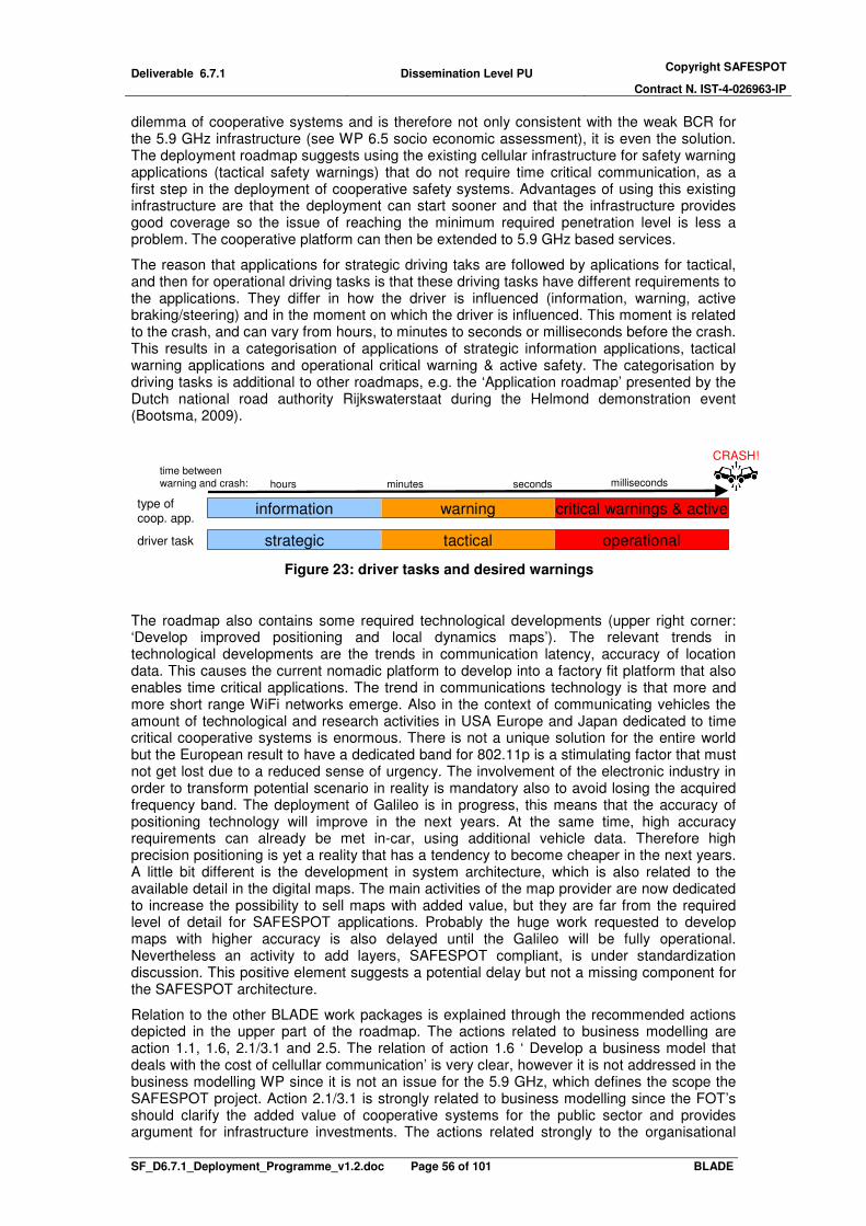
Deliverable 6.7.1 Dissemination Level PU Copyright SAFESPOT
Contract N. IST-4-026963-IP
SF_D6.7.1_Deployment_Programme_v1.2.doc Page 56 of 101 BLADE
dilemma of cooperative systems and is therefore not only consistent with the weak BCR for the 5.9 GHz infrastructure (see WP 6.5 socio economic assessment), it is even the solution. The deployment roadmap suggests using the existing cellular infrastructure for safety warning applications (tactical safety warnings) that do not require time critical communication, as a first step in the deployment of cooperative safety systems. Advantages of using this existing infrastructure are that the deployment can start sooner and that the infrastructure provides good coverage so the issue of reaching the minimum required penetration level is less a problem. The cooperative platform can then be extended to 5.9 GHz based services.
The reason that applications for strategic driving taks are followed by aplications for tactical, and then for operational driving tasks is that these driving tasks have different requirements to the applications. They differ in how the driver is influenced (information, warning, active braking/steering) and in the moment on which the driver is influenced. This moment is related to the crash, and can vary from hours, to minutes to seconds or milliseconds before the crash. This results in a categorisation of applications of strategic information applications, tactical warning applications and operational critical warning & active safety. The categorisation by driving tasks is additional to other roadmaps, e.g. the ‘Application roadmap’ presented by the Dutch national road authority Rijkswaterstaat during the Helmond demonstration event (Bootsma, 2009).
hours minutes seconds milliseconds
CRASH!
strategic tactical operational
information warning critical warnings & active
time between
warning and crash:
driver task
type of coop. app.
Figure 23: driver tasks and desired warnings
The roadmap also contains some required technological developments (upper right corner: ‘Develop improved positioning and local dynamics maps’). The relevant trends in technological developments are the trends in communication latency, accuracy of location data. This causes the current nomadic platform to develop into a factory fit platform that also enables time critical applications. The trend in communications technology is that more and more short range WiFi networks emerge. Also in the context of communicating vehicles the amount of technological and research activities in USA Europe and Japan dedicated to time critical cooperative systems is enormous. There is not a unique solution for the entire world but the European result to have a dedicated band for 802.11p is a stimulating factor that must not get lost due to a reduced sense of urgency. The involvement of the electronic industry in order to transform potential scenario in reality is mandatory also to avoid losing the acquired frequency band. The deployment of Galileo is in progress, this means that the accuracy of positioning technology will improve in the next years. At the same time, high accuracy requirements can already be met in-car, using additional vehicle data. Therefore high precision positioning is yet a reality that has a tendency to become cheaper in the next years. A little bit different is the development in system architecture, which is also related to the available detail in the digital maps. The main activities of the map provider are now dedicated to increase the possibility to sell maps with added value, but they are far from the required level of detail for SAFESPOT applications. Probably the huge work requested to develop maps with higher accuracy is also delayed until the Galileo will be fully operational. Nevertheless an activity to add layers, SAFESPOT compliant, is under standardization discussion. This positive element suggests a potential delay but not a missing component for the SAFESPOT architecture.
Relation to the other BLADE work packages is explained through the recommended actions depicted in the upper part of the roadmap. The actions related to business modelling are action 1.1, 1.6, 2.1/3.1 and 2.5. The relation of action 1.6 ‘ Develop a business model that deals with the cost of cellullar communication’ is very clear, however it is not addressed in the business modelling WP since it is not an issue for the 5.9 GHz, which defines the scope the SAFESPOT project. Action 2.1/3.1 is strongly related to business modelling since the FOT’s should clarify the added value of cooperative systems for the public sector and provides argument for infrastructure investments. The actions related strongly to the organisational

Deliverable 6.7.1 Dissemination Level PU Copyright SAFESPOT
Contract N. IST-4-026963-IP
SF_D6.7.1_Deployment_Programme_v1.2.doc Page 57 of 101 BLADE
architecture are actions 2.3 ‘Development of industry standards for V2X communication’ and 1.4 ‘Integrate nomadic tactical applications into the vehicle’. This action means that the car industry and the normadic service industry need to cooperate to fullfil the role of ‘SAFESPOT host on vehicle’. All of the recommendations have a legal component and represent risks and are discussed in the risk and legal analysis.
The BLADE deployment roadmap contains not only the typical SAFESPOT applications (time critical safety warnings based on 5.9 GHz communication). It also contains applications addressed e.g. in CVIS and COOPERS, as well as applications combining both the concepts of SAFESPOT and of CVIS/COOPERS. It has therefore a (slightly) different focus then in the other SAFESPOT sub projects. This different focus is due to different goals. The goal of the SAFESPOT sub projects aims at the technical proof of concept using short range 5.9 GHz communications. However, from a deployment perspective the deployment of these SAFESPOT systems is likely to take place in the broader context of cooperative systems (safety warning applications and other applications). Therefore deployment programme requires a different, wider scope then that of 5.9 GHz communications. Independent of this wider scope, the goal of the SAFESPOT deployment programme has always been to explore and discuss the deployment of 5.9 GHz based time critical safety warning systems. Moreover, each of the deployment scenarios as well as the deployment roadmap, do lead to the deployment of these typical 5.9 GHz SAFESPOT applications.

Deliverable 6.7.1 Dissemination Level PU Copyright SAFESPOT
Contract N. IST-4-026963-IP
SF_D6.7.1_Deployment_Programme_v1.2.doc Page 58 of 101 BLADE
6 Conclusions First, conclusions are presented based on the scenario analysis. In the first section, conclusions are on the transition from the current situation to the SAFESPOT system. These are based on the deployment roadmap. This is followed by the main challenges and the recommended actions for the stakeholders. As intended the, exploratory scenarios did provide insight in the deployment challenges. These deployment challenges are presented below. Although exploratory scenarios do not intend to identify a step by step plan for the stakeholders to reach an intended deployment path, some recommendations for the stakeholders are made. They are based on the deployment challenges and formulated in the interests of the stakeholders to whom they are addressed. This interpretation was a process in which the scenarios have been discussed within the BLADE team, the SAFESPOT core group and the CVIS general assembly. Finally a reflection on the work and the next steps is included.
6.1 Transition This section concludes with statements about the transition from the current situation to the situation where a SAFESPOT system that provides time critical safety warnings is a common part of the majority of vehicles. Deployment speed: When will we have a SAFESPOT system in the car? Cooperative systems are already commercially available in some form. TomTom is communicating real-time traffic information and a platform of smart phones with internet connection is emerging fast. However, the SAFESPOT system is defined as time critical safety system using 5G communication using the IEEE 802.11p standard. These SAFESPOT systems are expected to be commercially available between the year 2015 and 2020. From then it will take a few more years to overcome the barrier of reaching a minimum penetration of 5 percent equipped vehicles, for effective vehicle to vehicle communication will be realised in between 2020 and 2025. The year in which the system is expected to be available is an estimate based on the required time for the actions that need to be done to realise the market introduction, e.g. to define market standards, obtain argument for public investments and identify investment risks. The success of the FOTs anticipated for the next two to three years will be crucial for getting to the market introduction phase. After the market introduction the ‘deployment speed’ will be around 15% equipped vehicles extra each year. This expectation of the deployment speed is based on expert opinion of the market penetration of new vehicles combined with the vehicle age distribution within the vehicle fleet. A crucial factor that could speed up the deployment is whether nomadic devices could make SAFESPOT systems available for the existing vehicles in the fleet. In the deployment scenarios, the market penetration curves were differentiated by year of introduction and the deployment speed for the deployment scenarios (see also section 3.6.3). Application: Which functionality will the SAFESPOT system have? Is there a ‘killer application’? The applications that will emerge first are local hazard warning, congestion warning because they are not time critical so they can be provided on the existing nomadic platform. Which of these applications will indeed be the ‘killer application’ is not only difficult to predict, it is also less important for a deployment programme. What is important for a deployment programme is to realise that these non-time-critical applications, addressing the tactical driving tasks, are going to be there first. The timing of the safety warning is a crucial aspect. Not only because accurate timing determines the effectiveness of the warning, but also because different technology is required for time critical warnings and less time critical warnings. Different technical system configurations are required for warnings until one second before the potential accident, then for warnings within one second. This means that because tactical safety warnings can be provided on the existing communication infrastructure, they are likely to deploy before the time critical ones. The next question is which ‘killer’ application(s) will launch the short range communication technology. The killer app for the short range communication is ether a safety application or not. Since it is difficult to quantify the added value of safety, other systems that might be a ‘killer application’ in the sense that they launch the short range communication technology are

Deliverable 6.7.1 Dissemination Level PU Copyright SAFESPOT
Contract N. IST-4-026963-IP
SF_D6.7.1_Deployment_Programme_v1.2.doc Page 59 of 101 BLADE
a tolling system or cooperative ACC. Typical time critical safety applications that could be deployed after the ‘killer application’ has launched the short range technology platform are a lane change assistant or intersection safety applications. Platform: Which platforms for cooperative systems will be deployed? A platform is what enable the different cooperative applications. It consists of the enabling communication channels (both towards the driver and towards other vehicles/road side infrastructure), data, processing power and other elements, which are available to provide in-car applications for the driver. A clear conclusion regarding the platform is that applications will be provided based on communication with both vehicle to vehicle and vehicles to infrastructure. This is because the barriers to realise either pure vehicle to vehicle or a pure vehicle to infrastructure platforms are huge. There are many possible cooperative safety applications. The important question is which platform will be deployed, or, if several platforms can exist next to each other, the consequence is having several on-board units with several interfaces to the user. And consequently, which platform will support which applications? It is clear that time critical warning applications, addressing operational driving tasks, require a platform that enables short range communication technology and access to vehicle data to obtain sufficiently detailed location information (a SAFESPOT platform). Applications that address the tactical driving tasks could probably be provided on a platform using the current communication network and nomadic GPS. To realise a SAFESPOT platform, with short range cooperative safety applications, two possible paths are distinguished. One path is a transition from nomadic devices on existing long range cellular communication networks towards the in-car applications. The second path is the emerging of a new SAFESPOT platform dedicated for short range safety applications next to the emerging nomadic platform. According to a questionnaire at the CVIS project a multiservice platform will emerge. This is also supported by the conclusions of the societal analysis of cost and benefits. The technical aspects of cooperative systems will work and have the potential to offer significant safety benefits. The overall societal analysis of costs and benefits does not produce a clear cut positive conclusion. However, in order for deployment to take place, the business cases for the various providers will be strengthened if they do not rest on safety alone. Mechanisms for promoting the delivery of these services need to be identified.
6.2 Deployment challenges The following main deployment challenges are concluded from the challenges identified in the deployment scenarios. The challenges are followed by the proposed solution. Each challenge and its solution are explained briefly.
Reach critical mass: Intelligent road side infrastructure A major challenge is to reach sufficient penetration of equipped vehicles (about 5%) and equipped infrastructure to provide the safety applications. This is a challenge because with very few equipped vehicles, communication with others is less likely and less information is available. There are two main solutions to overcome this challenge. The first solution is system architecture that is infrastructure-based, beside supporting vehicle to vehicle communication). Investments on a limited number of roads/intersections would be most likely, but – just like a low penetration rate – this would cause that services are not widely available. It does however ensure quality of service is available with low penetration of equipped vehicles in the areas were it is needed most and the added value is high. These areas could be a start towards full geographical coverage. Cost savings, e.g. due replacing DRIPs by road side communication infrastructure, are major motivator for the public sector. Also, a potential benefit of this solution is use of the technology developed by the SAFESPOT project to enable road pricing. This gives the road operator and the public authorities an additional argument for investments. A second solution is to use the existing penetration of nomadic devices and the existing GSM/UMTS infrastructure. Several safety warnings can be provided through this existing platform, either by updating the software of existing nomadic on-board units or by new nomadic on-board units. This could be a launching pad for dedicated in car systems.
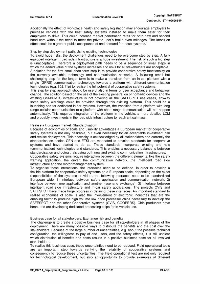
Deliverable 6.7.1 Dissemination Level PU Copyright SAFESPOT
Contract N. IST-4-026963-IP
SF_D6.7.1_Deployment_Programme_v1.2.doc Page 60 of 101 BLADE
Additionally the effect of workplace health and safety legislation may encourage employers to purchase vehicles with the best safety systems installed to make them safer for their employees to drive. This could increase market penetration rates for both new and second hand cars without the need to meet the private user’s brake-even mileages. The knock-on effect could be a greater public acceptance of and demand for these systems. Step by step deployment path: Using existing technologies To avoid huge risks, the deployment challenges need to be overcome step by step. A fully equipped intelligent road side infrastructure is a huge investment. The risk of such a big step is unacceptable. Therefore a deployment path needs to be a sequence of small steps in which the added value of the systems increases and risks for all stakeholders are acceptable. A solution for the first small short term step is to provide cooperative safety functionality on the currently available technology and communication networks. A following small but challenging step for the longer term is to make a transition from an in-car platform with a single (GPRS) communication technology, towards a platform with different communication technologies (e.g. 802.11p) to realise the full potential of cooperative safety systems. This step by step approach should be useful also in terms of user acceptance and behaviour change. The solution based on the use of the existing penetration of nomadic devices and the existing GSM/UMTS infrastructure is not covering all the SAFESPOT use cases, anyway some safety warnings could be provided through this existing platform. This could be a launching pad for dedicated in car systems. However, the transition from a platform with long range cellular communication to a platform with short range communication will not happen automatically. This requires integration of the platform in the vehicle, a more detailed LDM and probably investments in the road side infrastructure to reach critical mass. Realise a European market: Standardisation Because of economies of scale and usability advantages a European market for cooperative safety systems is not only desirable, but even necessary for an acceptable investment risk and realise deployment. This necessity is acknowledged by all stakeholders and currently the standardisation bodies CEN and ETSI are mandated to develop standards for cooperative systems and have started to do so. These standards incorporate existing and new (communication) technologies and standards. This enables a necessary balance is between standardisation and doing trials using both new and existing communication infrastructures. Cooperative safety systems require interaction between the different elements, like the safety warning application, the driver, the communication network, the intelligent road side infrastructure and the motor management system. To organise these interactions, the interfaces need to be defined. In order to develop a flexible platform for cooperative safety systems on a European scale, depending on the exact responsibilities of the systems providers, the following interfaces need to be standardized European wide. 1) interface between safety application and communication network, 2) interface between one application and another (scenario exchange), 3) interface between intelligent road side infrastructure and in-car safety applications. The projects CVIS and SAFESPOT have made huge progress in defining these interfaces. An important standard to realise economies of scale is also the involvement of electronic industries that are the enabling factor to produce high volume low price processor chips necessary to develop the SAFESPOT and the other Cooperative systems (CVIS, COOPERS). Chip producers have been, and are developing dedicated processing chips for in-vehicle use. Business case for all stakeholders: Exchange risk and benefits The challenge is to create a positive business case for all stakeholders in all phases of the deployment. There are many possible ways to distribute the benefits and the cost over the stakeholders. Because of the large number of uncertainties, e.g. about the possible technical configuration, the willingness to pay of end users, and the safety effects, it is still unclear which distribution of benefits and costs results in a positive business case for all involved stakeholders. To realise this business case, these uncertainties need to be reduced. Field operational tests are an important step towards verifying the reliability of cooperative systems and consequently to reduce these uncertainties. The Field operational test are not only required for technological development, but also an opportunity to provide examples of different
Deliverable 6.7.1 Dissemination Level PU Copyright SAFESPOT
Contract N. IST-4-026963-IP
SF_D6.7.1_Deployment_Programme_v1.2.doc Page 61 of 101 BLADE
technical system configurations; a way to support the benefits of these systems with real-life data, and a more rationale way to verify the user acceptance, to educate the driver society. Cooperation between the stakeholders: Decision making process Cooperation between the main stakeholders is required for the deployment of cooperative safety systems. None of the main stakeholders can realize cooperative safety systems by themselves. To realise cooperation, a decision making process needs to be initialized and be organized, which means getting the relevant stakeholders involved, setting the agenda, and decision making procedures. Someone needs to take up this role of process manager, and to be the ‘Mr. Cooperative Safety Systems’. An example of a successfully managed decision making process in the past is the deployment of the internet. Federal agencies made and implemented several other policy decisions which shaped the Internet of today, and then took the role of ‘Mr. Internet’. For the Cooperative systems a potential candidate could be the eSafety forum or the EC through the ITS Action Plan. An important aspect in the decision making process is to maintain the sense of urgency. This urgency is important to maintain the allocated frequencies for short range in-vehicle safety services; otherwise the spectrum will be used for other purposes.
6.3 Recommendations for the main stakeholders Recommended actions: Each recommended action is linked to a deployment challenge and assigned to a stakeholder based on the results of the workshop with the BLADE team. An important conclusion for the formulation of recommendations is that these challenges are interpreted differently by the different stakeholders. This is due to their varying interests. The recommended actions are therefore formulated in such a way that the action is in the interest of the stakeholder and in the interest of realising cooperative safety systems. The most important recommended actions are formulated for the main stakeholder groups, being road authorities, car manufactures and (nomadic) service providers.
Road authorities and road operators Cooperative safety systems have huge potential benefits for road authorities and road operators (as well as for policy makers such as ministries of transport). It is therefore in their interest to actively take part in the deployment of cooperative safety systems in order to realise these potential benefits like cost reduction, less traffic accidents and better throughput. Depending on the roles they see for themselves, their position regarding cooperative systems will be slightly different and probably other recommendations could be formulated. It is good to realise that responsibilities of these actors could differ from those of the road authorities. The scope of these policy makers should be wider and also include influencing the total traffic demand and all modes of transport. Recommendations for this group could differ from those for the road authority or a road operator. However, since the benefits of cooperative systems, e.g. collecting floating car data, are in the interest of both road authorities and policy makers, a general recommendation is to participate actively in field trials, research projects, standardisation committees and in the decision making processes on cooperative systems in order to realise those benefits. A second recommendation is to experiment with cost reduction calculations of replacing DRIPs by road side communication infrastructure. No regret action: Invest and participate in field operational test in order to obtain arguments for government investments and in order to get experience with public private partnerships in this area. Car industry Car manufacturers are in a critical position from the market perspective. Their critical position is an opportunity to introduce de facto standards, but also to prevent standards and develop a more proprietary system (brand specific). Standards could be adopted on the communication level, on the application level and on the vehicle data level. The industry should develop standards on the vehicle data level (for the interface to the motor management system and the in-car sensors). This results in a more flexible platform which gives road users the choice to select any available application they want. This is likely to be a competitive advantage to a more rigid proprietary system. In case of a rigid proprietary system, providers of nomadic devices are likely to take a big part the new market of in-car services.

Deliverable 6.7.1 Dissemination Level PU Copyright SAFESPOT
Contract N. IST-4-026963-IP
SF_D6.7.1_Deployment_Programme_v1.2.doc Page 62 of 101 BLADE
No regret action: The car manufacturers should develop an interface for access to the motor management system and sensor data, in order to offer value added cooperative safety applications to their customers.
(Navigation) service providers should develop new applications on the nomadic platform that they have currently deployed in order to extend their maturing market. By expanding the range of applications from navigation towards, among others, cooperative safety applications they can keep on extending their market potential of in-car services. Some safety applications, e.g. Speed Alert or Local Hazard Warning, they can provide without help from other important stakeholders like the car manufacturers or road authorities. This does however depend on the position of the car manufacturers, especially for active safety assistance applications, and it depends on the information provision for road authorities in case of traffic management applications like dynamic speed alert or road pricing. No regret action: Develop cooperative safety applications on the existing nomadic navigation platform based on GPRS technology. These recommendations are validated with the stakeholders. The stakeholders have indicated in a questionnaire that they agree with these main recommendations.
6.4 Reflection on the results and research method The focus is shifting from technological challenges towards deployment challenges. Not only in the SAFESPOT project team, but also in the CVIS and Coopers project the relevance of solving deployment issues is recognized.
Despite the great progress in the SAFESPOT project in the last four years in the technical field, there is still a lot of uncertainty about the configuration and functionality of the SAFESPOT cooperative safety system. Therefore the scope of possible future developments is immense and inevitable, leading to the analysis and conclusions being made on a general level. The applied scenario methodology allows for in-depth analysis on a specific system due to the specific context that is defined by the scenarios. Also the communicative function of the scenarios proved to be useful. It is clear that the remaining uncertainty leaves open many recommendations for further research on deployment. The most important recommendation is to test SAFESPOT (short range safety applications) in FOTs. Another important open issue is the competition from long range safety applications. A relevant question for the deployment of the (short range) SAFESPOT system is to specify which cooperative safety warnings can be provided based on existing positioning technology and communication infrastructure and which require new high precision positioning data and low latency short range communication infrastructure.

Deliverable 6.7.1 Dissemination Level PU Copyright SAFESPOT
Contract N. IST-4-026963-IP
SF_D6.7.1_Deployment_Programme_v1.2.doc Page 63 of 101 BLADE
References
• Arem, B. van, Hagemeier F., Sol E.-J., A 5 generation reference model for intelligent cars in the twenty-first century, ITS world Conferen 2008, http://www.aida.utwente.nl/research/publications/EJS-ITS08.pdf
• Bootsma, G., 2009 Cooperative systems from a road authority point of view From policy to implementation, Rijkswaterstaat Centre for Transport and Navigation, Ministery of Traffic & Transport, The Netherlands, presentation Helmond demonstration event 22 mei 2009
• Demmel, S., Gruyer, D., Rakotonirainy A., Articulating cooperatives systems and driver behaviour theories, ITS world conference, 21-25 Sept. 2009, Stockholm Sweden
• CoCar Consortium, CoCar Feasibility Study - Technology, Business and Dissemination, Public Report, 2009, p2
• CVIS 2009, Brochure on CVIS, CALM and COMM, http://www.cvisproject.org/download/qfree_CommCalmCvis_aalborgbrochure.pdf, last visited 13-12-2009
• EUCAR website, http://www.eucar.be/start.html, last visited 23/12/2008
• European Commission 2008: Energy and Transport - Trends to 2030, Update 2007, Luxembourg 2008.
• European Commission 2006, On the Intelligent Car Initiative "Raising Awareness of ICT for Smarter, Safer and Cleaner Vehicles", Brussels, 15.2.2006
• Herrtwich, R. 2003: E-Cars, Communication on the Road, IFIP I3E Conference, Sao Paulo
• Malone et al, Socio-economic Impact Assessment of Stand-alone and Co-operative Intelligent Vehicle Safety Systems (IVSS) in Europe, Deliverable D2 eImpact, eIMPACT Consortium, 24/04/2006
• NXP, ATOP from NXP: the basis for a new international private car road pricing system, April 2008, The Netherlands, http://www.nxp.com/documents/other/75016515.pdf
• SAFESPOT SP6 WP6.3 (2009),Organisational Architecture D6.3.1, Preliminary Organisational Architecture, SAFESPOT sub-project 6 (“BLADE – Business models, Legal Aspects, and DEployment”), work package 3
• SAFESPOT SP6 WP6.4 (2009),Organisational Architecture D6.4.5, Preliminary Recommendations based on Risk and Legal Analysis, SAFESPOT sub-project 6 (“BLADE – Business models, Legal Aspects, and DEployment”), work package 4
• SAFESPOT SP6 WP6.5 (2009), Assessment & Evaluation, Deliverable D6.5.1Socio-economic assessment, SAFESPOT sub-project 6 (“BLADE – Business models, Legal Aspects, and DEployment”), work package 5
• SAFESPOT SP6 WP6.6 (2009), Service and Business Model Definition, Deliverable D6.6.1 Definition Alternative Service & Business Models, SAFESPOT sub-project 6 (“BLADE – Business models, Legal Aspects, and DEployment”), work package 6
• SAFESPOT SP6 WP6.7 (2009), SAFESPOT Deployment Programme, Deliverable D6.7.2, Report of the workshop on the SAFESPOT deployment programme, SAFESPOT sub-project 6 (“BLADE – Business models, Legal Aspects, and DEployment”), work package 7
• SAFESPOT Technical Annex, SAFESPOT project plan, 2009
• Sondeijker, S., Imagining Sustainabilit, Methodological building blocks for transition scenarios, 9 december 2009, Thesis Erasmus University Rotterdam ISBN: 978-90-8559-565-6
Deliverable 6.7.1 Dissemination Level PU Copyright SAFESPOT
Contract N. IST-4-026963-IP
SF_D6.7.1_Deployment_Programme_v1.2.doc Page 64 of 101 BLADE
• TNO, Scenario’s – definities & methodiek [Scenarios – definitions & methodology], Delft, December 1994.
• TomTom, White paper How TomTom’s HD Traffic™ and IQ Routes™ data provides the very best routing, Travel Time Measurements using GSM and GPS Probe Data, http://www.tomtom.com/lib/doc/download/HDT_White_Paper.pdf, last visited 22-02-2010
• Wees, K. van, Robery, M., Clark, D., Analysis of legal aspects, Year 2 review presentation, Turin, May 15, 2008
• Van Wees, K., Robery, M., Analysis of legal aspects, Year 2 review presentation, Turin, May 15, 2008

Deliverable 6.7.1 Dissemination Level PU Copyright SAFESPOT
Contract N. IST-4-026963-IP
SF_D6.7.1_Deployment_Programme_v1.2.doc Page 65 of 101 BLADE
Annex 1. Deployment factors The deployment factors are derived from the risks defined in the risk analysis (D 6.4.1). For every risk in the risk table in deliverable D6.4.1, a deployment factor identified.
This results in the following list of 18 scalable factors.
Scalable factors
compatibility
safety effects
financing
functionality
geographical coverage
government involvement
regulation
allocation of liability
market demand
organisational complexity
penetration
privacy concerns
quality of service
synergy with other in-car systems
system costs
technical feasibility
The most important aspects of the deployment factors for the definition of the scenario base are the level of influence and level of uncertainty. They have been filled in below. The level of influence is rated from 1 to 10, where 1 corresponds to a very low influence on the deployment speed of SAFESPOT, and 10 corresponds to a very high influence on the deployment speed. The level of uncertainty is rated from 1 to 10, where 1 corresponds to a very low uncertainty about the different values that a factor can have in different scenarios. This means that a low uncertainty score means that the value most certainly the same for the different scenarios. A high score means that the value could vary a lot in the different scenarios. Other aspects that are described are the current situation, expected development, other possible results and possible trend breaks. The 18 identified deployment factors are described in terms of definition, current situation, expected development, other possible results/developments, level of influence on the deployment, level of uncertainty and trend breaks.

Deliverable 6.7.1 Dissemination Level PU Copyright SAFESPOT
Contract N. IST-4-026963-IP
SF_D6.7.1_Deployment_Programme_v1.2.doc Page 66 of 101 BLADE
compatibility
Definition
The extent to which vehicles and infrastructures understand each other’s messages Current situation
Because there are no service and service provider yet, there is no compatibility with other cooperative safety systems or other in-vehicle systems. There may be an issue of compatibility with existing European DSRC used for Electronic Fee Collection. CVIS VANET board is already taking into account this aspect but a full solution has not been assessed. Expected development
In scenarios with a ‘safe spot’ roll out in combination with different service providers it is expected that these systems will not be compatible. However, this may create strong motivation for realising standards. Other possible results/developments
Standards will have to be imposed legally to enforce compatibility for systems from different, possible competing service providers. Level of influence
The compatibility influences the implementation speed mainly through the quality of service and the market demand. This influence on quality of service is rather strong, but the influence of quality of service on market demand may not be. (Score 6) Level of uncertainty
Compatibility depends on the organisation and on legislation. How this relations relationship will develop is unclear. (Score 8) Trend breaks
financing complexity
Definition
The number of different flows of money between the stakeholders. Current situation
Currently there is no service and therefore there is no financing model. Two possible ways of financing are through public (tax) money or by end user payment. Expected development
In a first stage public (tax) money could stimulate the penetration to reach the minimum threshold. Later the pay per use principle could be more appropriate. Other possible results/developments
Level of influence
Financing structure is an element of the business model. The complexity depends on the way in which the financing is organised and does not have much influence on the deployment speed. (Score 4) Level of uncertainty
The way in which the financing is organised is highly uncertain because it depends on many uncertain factors, and the influence of these factors on financing is also uncertain because politics play an important role. The factors that influence the financing are the government involvement and the business case, which is the difference between the willingness to pay and the system costs. (Score 9)

Deliverable 6.7.1 Dissemination Level PU Copyright SAFESPOT
Contract N. IST-4-026963-IP
SF_D6.7.1_Deployment_Programme_v1.2.doc Page 67 of 101 BLADE
functionality
Definition
The bundle of applications which is provided by the system. This bundle can contain a combination of safety applications and other services like traffic information, commercial information or entertainment services. The safety applications can be other than the six applications defined in BLADE, however, the scenario description is based on a combination of the BLADE applications in order to be able to determine the cost benefit results. Current situation
- Expected development
Other possible results/developments
Level of influence
The functionality influences two important factors, market demand and system costs. More functionality means higher market demand and thus higher penetration rates, but also higher systems costs and thus lower penetration rates. Although the functionality itself is uncertain, the effect on the deployment speed is both positive and negative and therefore the influence is less. (Score 6) Level of uncertainty
The preference for certain functionality depends on the market demand, technical feasibility and organisational preconditions. How these factors determine the functionality is not clear. (Score 8) Trend breaks
geographical coverage
Definition
With respect to the V2I applications the geographical coverage relates to that part of the road network that is equipped. With respect to V2V applications the geographical coverage relates to that part of the network were the minimum penetration for the specific applications is achieved. Current situation
Currently there is no service available and therefore there is no coverage. Expected development
Other possible results/developments
Level of influence
The influence on the deployment speed is quite big, because it is directly related to the penetration. (Score 7) Level of uncertainty
Because the geographical coverage strongly depends on the penetration, for V2V applications, the uncertainty in this respect is not so high. However, the uncertainty for the geographical coverage for the V2I applications is high because it is not clear how it depends on the government involvement. (Score 6) Trend breaks
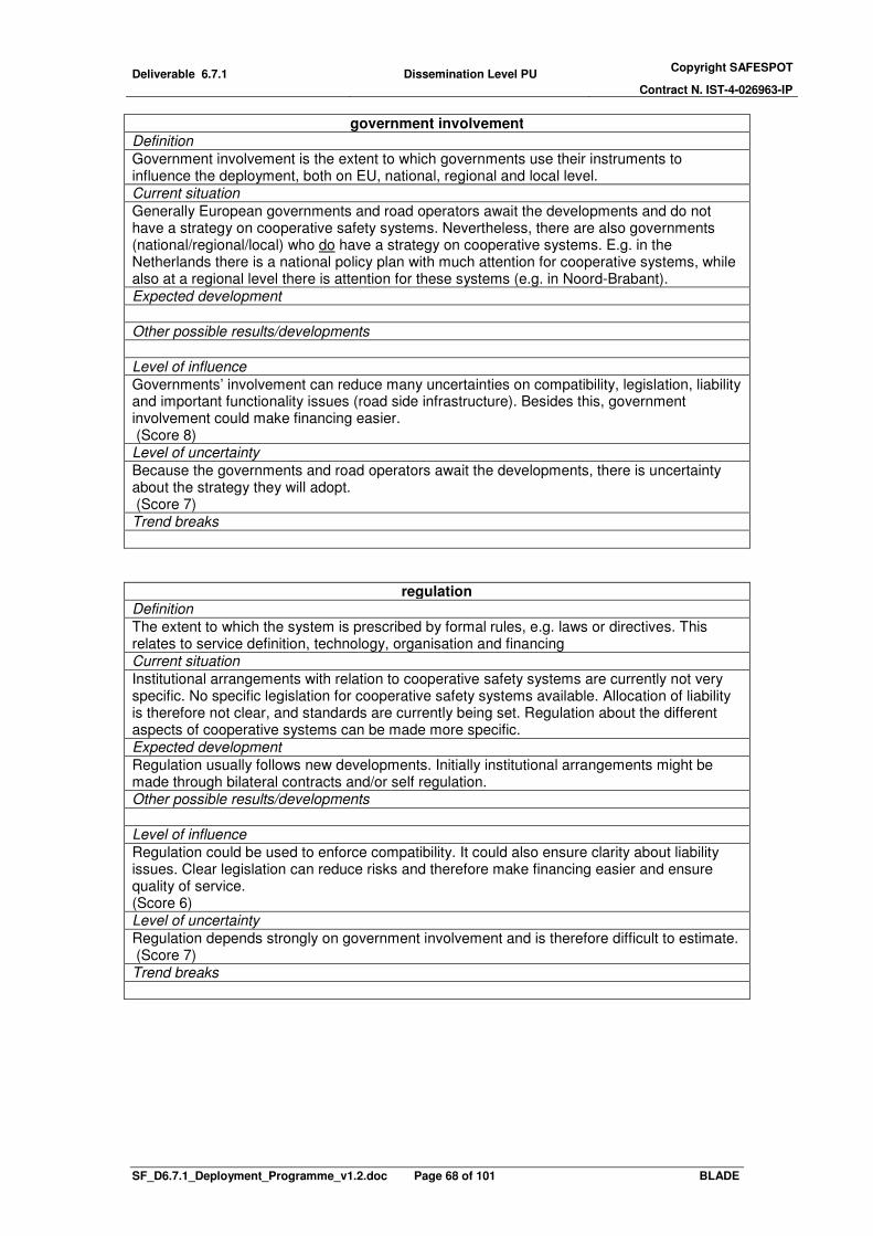
Deliverable 6.7.1 Dissemination Level PU Copyright SAFESPOT
Contract N. IST-4-026963-IP
SF_D6.7.1_Deployment_Programme_v1.2.doc Page 68 of 101 BLADE
government involvement
Definition
Government involvement is the extent to which governments use their instruments to influence the deployment, both on EU, national, regional and local level. Current situation
Generally European governments and road operators await the developments and do not have a strategy on cooperative safety systems. Nevertheless, there are also governments (national/regional/local) who do have a strategy on cooperative systems. E.g. in the Netherlands there is a national policy plan with much attention for cooperative systems, while also at a regional level there is attention for these systems (e.g. in Noord-Brabant). Expected development
Other possible results/developments
Level of influence
Governments’ involvement can reduce many uncertainties on compatibility, legislation, liability and important functionality issues (road side infrastructure). Besides this, government involvement could make financing easier. (Score 8) Level of uncertainty
Because the governments and road operators await the developments, there is uncertainty about the strategy they will adopt. (Score 7) Trend breaks
regulation
Definition
The extent to which the system is prescribed by formal rules, e.g. laws or directives. This relates to service definition, technology, organisation and financing Current situation
Institutional arrangements with relation to cooperative safety systems are currently not very specific. No specific legislation for cooperative safety systems available. Allocation of liability is therefore not clear, and standards are currently being set. Regulation about the different aspects of cooperative systems can be made more specific. Expected development
Regulation usually follows new developments. Initially institutional arrangements might be made through bilateral contracts and/or self regulation. Other possible results/developments
Level of influence
Regulation could be used to enforce compatibility. It could also ensure clarity about liability issues. Clear legislation can reduce risks and therefore make financing easier and ensure quality of service. (Score 6) Level of uncertainty
Regulation depends strongly on government involvement and is therefore difficult to estimate. (Score 7) Trend breaks

Deliverable 6.7.1 Dissemination Level PU Copyright SAFESPOT
Contract N. IST-4-026963-IP
SF_D6.7.1_Deployment_Programme_v1.2.doc Page 69 of 101 BLADE
clear liability
Definition
The extent to which it is clear as to which specific stakeholders liabilities are assigned. Current situation
Current legislation is for instance not explicit about who is liable if a Safespot system causes an accident. Legislation applicable to liability issues is consumer product legislation. An important issue is whether or not an in-car data recorder is used because it provides evidence on which liability may be assigned. Expected development
Other possible results/developments
Level of influence
The factor liability influences where the risks are. Either the end user is liable or the system provider. Being liable results in financial risks in case of accidents. For system providers the compensation of this risk results in higher system costs. For end users, the liability results in lower demand. (Score 4) Level of uncertainty
The influence of liability is rather uncertain because this depends on how the legislation is interpreted by a judge for specific configuration of the system in a specific situation. (Score 8) Trend breaks
market demand
Definition
The size of the market of cooperative safety systems in euros. This is the product of price and quantity (p x q)
Current situation
- Expected development
Other possible results/developments
Level of influence
The market demand influences directly the penetration rates, which is the measure for deployment speed. Market demand is an important factor in the penetration rates. (Score 8) Level of uncertainty
The uncertainty of the market demand is high because it influenced many factors. From most of these factors, e.g. functionality, quality of service, market demand, etc, the influence the market demand is unclear. (Score 8) Trend breaks

Deliverable 6.7.1 Dissemination Level PU Copyright SAFESPOT
Contract N. IST-4-026963-IP
SF_D6.7.1_Deployment_Programme_v1.2.doc Page 70 of 101 BLADE
organisational complexity
Definition
This relates to the number and types of relations between the stakeholders of cooperative safety systems. A relationship between two stakeholders is for instance a buyer-supplier relationship, or a concession holder-concession giver relationship. Generally more stakeholders mean more relationships and thus more organisational complexity. The type of relationship can also be more or less complex. The relationship of a customer with a car dealer is less complex than a road operator with a ministry of transport. Current situation
The organisational complexity describes which stakeholders perform which roles. More stakeholders with significant roles lead to more organisational complexity. The roles required for providing the SAFESPOT service have been identified. There is however no service yet, and most stakeholders have not yet expressed which roles they see for themselves and others. Expected development
Other possible results/developments
Level of influence
The organisational complexity only influences the compatibility and does therefore not have much influence. (Score 4) Level of uncertainty
The organisational complexity depends on the government involvement and on the intentions of other stakeholders. Most stakeholders have not yet expressed which roles they see for themselves and others, so this is still unclear. (Score 7) Trend breaks
penetration
Definition
The part of the vehicle fleet which is equipped with the SAFESPOT system Current situation
- Expected development
Other possible results/developments
Level of influence
Penetration is a measure for the deployment. Therefore the influence is very high. Besides this penetration has a big influence on the safety effects. (Score 9) Level of uncertainty
The trend for penetration is estimated based on the circulation of the vehicle fleet. This estimate, given a certain demand, gives a reasonable idea of the penetration. Other factors that determine the penetration are the demand and the costs for the end user. This relationship is well understood. So given the, in itself, uncertain factor of market demand, the uncertainty in the penetration is limited. (Score 6) Trend breaks
privacy concerns
Definition
The objections of end users and policy makers against registration and communication of personal data or location of their vehicle. Current situation

Deliverable 6.7.1 Dissemination Level PU Copyright SAFESPOT
Contract N. IST-4-026963-IP
SF_D6.7.1_Deployment_Programme_v1.2.doc Page 71 of 101 BLADE
Expected development
Other possible results/developments
Level of influence
Privacy is one of many factors that influence market demand, and may not be very crucial because high privacy concerns can be compensated by the technical specification of the system (how well are personal data protected?). Therefore the level of influence is low. (Score 4) Level of uncertainty
The influence of privacy concerns depends on how serious these concerns are, and on the technical configuration (how well does the system protect personal data?). Although both are unclear, they compensate each other. The uncertainty score is therefore moderate. (Score 6) Trend breaks
quality of service
Definition
The performance of the service in terms of how often the system fails to warn or generates incorrect messages. Another issue is the quality of the human machine interface (HMI), e.g. how well it deals with overload or prioritisation of messages. Current situation
Expected development
Other possible results/developments
Level of influence
If a system doesn’t function properly (wrong messages, unfriendly interface) this has a strong influence on the market demand. Besides that, it could have an influence on the safety effects as well. Therefore the influence is still reasonably big. (Score 7) Level of uncertainty
It is however something that can be optimised by testing and solving problems quickly to prevent the negative effect on the deployment getting to large. This mechanism will likely result in a sufficient quality of service not to affect demand in a negative way. Therefore the uncertainty is rather low (Score 5) Trend breaks
synergy with other in-car systems
Definition
The extent to which different functionality can be offered on the same platform. An example is that in-car information services can be provided on the same human machine interface, and different safety applications can use the same sensors or communication technology. The main advantage is cost reduction. Current situation
Expected development
Other possible results/developments
Level of influence
The synergy with other systems has a high influence on the systems costs, and through that, indirectly on the penetration.

Deliverable 6.7.1 Dissemination Level PU Copyright SAFESPOT
Contract N. IST-4-026963-IP
SF_D6.7.1_Deployment_Programme_v1.2.doc Page 72 of 101 BLADE
(Score 8) Level of uncertainty
The uncertainty is however rather high because the synergy depends on the technical configuration, both of the SAFESPOT functionality as other in-car functionality, e.g. traffic information. Beside this, the financing and organisation is much more complicated which increases uncertainty (Score 8) Trend breaks
safety effects
Definition
The reduction in the number of road traffic incidents which result in casualties and severe injuries. Current situation
Currently there is no service and therefore there are currently no effects. Expected development
Estimates of the effects of cooperative safety systems are being made. Effects for the systems in de SAFESPOT BLADE bundles for V2V and V2I can be found in the SAFESPOT socio economic impact assesment (D6.5.1). Other possible results/developments
The safety effects depend on the functionality of the system and the penetration in the vehicle fleet. Level of influence
The safety effects determined are an important argument for government involvement. This is an important influence. (Score 7) Level of uncertainty
The effect strongly depends on the penetration and the functionality. Given estimates for these two factors the safety effect can be determined without much uncertainty. (Score 4) Trend breaks
The effects will only be visible after a certain minimum penetration. Then the effect will strongly increase with an increasing penetration and finally the increase the penetration will result in less and less extra effect because the traffic is already very safe.
system costs per equipped vehicle Definition
Average costs per equipped vehicle to offer the functionality Current situation
Expected development
Other possible results/developments
Level of influence
System costs have a direct influence on the penetration, and thus on the deployment speed of the SAFESPOT system. (Score 9) Level of uncertainty
The system cost, given a specific functionality and corresponding technical configuration, can be estimated rather well. Some uncertainty is caused by the possible liability risks, but given clear liability arrangements, the costs of this risk can be estimated as well. (Score 3) Trend breaks

Deliverable 6.7.1 Dissemination Level PU Copyright SAFESPOT
Contract N. IST-4-026963-IP
SF_D6.7.1_Deployment_Programme_v1.2.doc Page 73 of 101 BLADE
technical feasibility
Definition
The extent to which it is technically possible to develop the intended functionality. This can be expressed in terms of the technology readiness level as developed by the NASA. Current situation
Expected development
Other possible results/developments
Level of influence
The technical feasibility influences the functionality and the difficulty in achieving good quality of service. These are both important factors for the market demand, and thus for the penetration. The effect is however indirect. (Score 7) Level of uncertainty
The technology for the anticipated functionality is available as components, but not yet integrated. This is currently being done and technical feasibility is not expected to be a problem. (Score 3) Trend breaks

Deliverable 6.7.1 Dissemination Level PU Copyright SAFESPOT
Contract N. IST-4-026963-IP
SF_D6.7.1_Deployment_Programme_v1.2.doc Page 74 of 101 BLADE
Annex 2. Basic scenarios
Basic scenario 1. You shall all be safe!
Deployment path Milestones
� Large scale European Field Operational Test (FOT) with Cooperative ACC with speed and distance warning (LONC) successfully demonstrates the safety benefits.
� European law is passed that makes the installation of this C-ACC with warnings mandatory in all new cars
� Installation is subsidized by several national governments (subsidy reduces as penetration increases)
Penetration curve
� high deployment speed; mandatory equipment of 100% of the new vehicles � early take off; European law is implemented, translated into national legislation and
effectuated in 2015.
Storyline The mandatory introduction of eCall in all new vehicles by the European Commission is considered a success. Like the case of seatbelts, ABS, ESC and eCall, EC extends this policy of mandatory safety applications to cooperative safety applications. European scale FOT with a cooperative ACC with longitudinal collision and speed limit warning (LONC) is organised by EC. The advantage of choosing C-ACC as a first application is that it has safety effects, throughput effects and emission effects. A minimum penetration level in the FOT is reached by equipping, amongst others, public organisations such as bus companies, national and regional road operators and national governments participate as launching customers. The evaluation shows significant safety effects and a positive cost benefit ratio. Even with 10% penetration the effects on safety, and even on throughput, top expectations. In 2015 a European law is passed that makes the installation of this C-ACC with warnings mandatory in all new cars (on manually geared cars only a longitudinal collision and speed limit warning are mandatory). Although mandatory, initially the system is heavily subsidized. The subsidies are reduced as the penetration increases. Later other safety applications, Local Hazard Warning (RODP) and Intersection collision application (LATC) are added to the bundle of mandatory safety applications in all new vehicles.
Expected situation in 2020
high deployment speed: 12 years
take off: 2015
20352010
eq
uip
pe
d n
ew
veh
icle
s 80%
10%
2015

Deliverable 6.7.1 Dissemination Level PU Copyright SAFESPOT
Contract N. IST-4-026963-IP
SF_D6.7.1_Deployment_Programme_v1.2.doc Page 75 of 101 BLADE
YOU SHALL ALLBE SAFE!
V2IV2V
generic platform
SAFESPOT platform
private lead
public lead
� The platform consists of on-board units that communicate with each other using short
range communication technology. The platform provides C-ACC with speed and distance warning (LONC). This is mandatory in all new cars.
� Car buyer pays for mandatory system (Safespot business model 3) � first 10% of the market and aftermarket systems are subsidized by national
governments � High penetration complete fleet: about 41% � high BCR: about 1.6 (LONC functionality)
� BCR > 1 from introduction (year 2015)

Deliverable 6.7.1 Dissemination Level PU Copyright SAFESPOT
Contract N. IST-4-026963-IP
SF_D6.7.1_Deployment_Programme_v1.2.doc Page 76 of 101 BLADE
Basic scenario 2. Societal quantity discount Deployment path Milestones
� Road pricing based on V2I is being introduced � Tender for offering V2V Local Hazard Warning on the road pricing platform (RODP
based on GPRS) � Platform is opened up for car-manufacturers to offer time critical V2V (safety)
applications and active safety systems based on short range communication (802.11p)
Penetration curve
� High deployment speed; the road pricing platform is likely to be implemented very fast and with it also the local hazard warning application.
� Normal take off (2020);
Storyline In this scenario the national road authorities play an important role in V2V services. Their main interest is to stay in control of traffic management in a cost efficient way. V2V services can be provided without the high expenses of road side communication, and the car as a sensor is a cost efficient way to monitor the network. A second public interest is to improve road safety. Road pricing based on V2I communication is introduced. The privately developed but functionally regulated OBU’s are completely paid/subsidized from tax money. A retrofit/aftermarket solution is provided for the existing vehicles. V2V safety applications are provided on this platform by the car industry. Also these safety applications will have to comply with strict functional regulation. A service fee needs to be paid for these extra functionalities. Real time travel and traffic information is collected and provided by a national government owned organisation. To be able to manage traffic, there is strict regulation about the functionality of services like speed alert, local hazard warning, providing travel information. The information that is minimally required from the infrastructure, such as dynamic speed limits and travel information is provided by simple infrastructure beacons. A European vehicle to vehicle communication standard is developed with the car industry and road operators in Integrated European Projects from the 6
th and 7th Framework Programme,
based on short range communication. An open platform is deployed on which both private parties and road authorities can offer different types of applications. This deployment is stimulated by the government in three ways. First of all the bandwidth for communication is provided for free. Secondly, the EC invested in the development of an industry wide V2V short range communication standard. Thirdly, the national governments subsidize the in-car
take off: 2020
20352010
equ
ipp
ed n
ew
veh
icle
s 80%
10%
2015
high deployment
speed: 12 years

Deliverable 6.7.1 Dissemination Level PU Copyright SAFESPOT
Contract N. IST-4-026963-IP
SF_D6.7.1_Deployment_Programme_v1.2.doc Page 77 of 101 BLADE
unit when it meets requirements of openness and compatibility with the communication standard.
Expected situation in 2020
SOCIETAL QUANTITYDISCOUNT
V2IV2V
generic platform
SAFESPOT platform public lead
private lead
� The platform consists of on-board units, using short range communication technology
to communicate with other vehicles and long range cellular network to receive information from a service centre for the non-time-critical services like traffic information. Time critical services that are provided based on short range V2V communication are, local hazard warning, speed alert and cooperative ACC with speed and distance warning (LONC)
� Government pays for road pricing, local hazard and speed alert. Road user pays for extra traffic info C-ACC (longitudinal collision and speed limit warning on manually geared cars)(Safespot business model 7)
� BCR > 1 from year XX (RODP functionality) � Penetration complete fleet: between 5 and 16 %
� High deployment speed � Normal take off

Deliverable 6.7.1 Dissemination Level PU Copyright SAFESPOT
Contract N. IST-4-026963-IP
SF_D6.7.1_Deployment_Programme_v1.2.doc Page 78 of 101 BLADE
Basic scenario 3. We want safety! Deployment path Milestones
� Volvo introduces V2V (Volvo to Volvo) C-ACC with safety warnings (LONC functionality)
� Other Car-manufacturers follow � C2C becomes reality (European standard) � Car manufacturers make alliances to achieve higher penetration of compatible
vehicles � Cooperative ACC is launched by a number of car manufacturers � Other applications follow (Local hazard warning (RODP) & intersection safety
(LATC)) Penetration curve
� Normal deployment speed � Normal take off
Storyline Road administrations don’t have much interest in cooperative safety systems. Therefore private parties, car manufacturers in this case, take the lead. Car-manufacturers already introduced standalone safety applications in the higher market segment, e.g. vulnerable road user systems, C-ACC and emergency braking. They see in ADAs, especially in safety oriented systems, an opportunity to differentiate from competitors and win customers. The car manufacturers compete on the performance of these systems. Communication between vehicles (short-range) enables improvement in performance of these ADAS with warning systems. With support from the EC the car industry finalises and agrees on the standards for short range V2V communication as they are currently being developed in the C2C consortium. ETSI and CEN acknowledge and formalise the standard. To achieve a sufficient penetration of equipped vehicles, a number of car manufactures introduce V2V C-ACC. Other car manufacturers follow and also other C2C applications are introduced.
Expected situation in 2020
deployment speed: 20 years
take off: 2020
20352010
eq
uip
pe
d n
ew
vehic
les 80%
10%
2015

Deliverable 6.7.1 Dissemination Level PU Copyright SAFESPOT
Contract N. IST-4-026963-IP
SF_D6.7.1_Deployment_Programme_v1.2.doc Page 79 of 101 BLADE
V2IV2V
generic platform
SAFESPOT platform
WE WANTSAFETY!
public lead
private lead
� The platform consists of on-board units using short range communication technology to communicate with each other. The platform supports the services stand alone braking assistance, stand alone vulnerable road user application, local hazard warning, speed alert and cooperative ACC with speed and distance warning (LONC)
� Car buyer pays when they buy the car (Safespot business model 5) � BCR > 1 from year 2020 (LONC functionality) � Penetration complete fleet : about 5 %

Deliverable 6.7.1 Dissemination Level PU Copyright SAFESPOT
Contract N. IST-4-026963-IP
SF_D6.7.1_Deployment_Programme_v1.2.doc Page 80 of 101 BLADE
Basic scenario 4. Technology pushed ITS revolution Deployment path Milestones
� PND industry offer, next to real-time traffic information and infotainment, speed alert (V2V SpA) and Local Hazard Warning, based (RODP) and will try to offer any possible service on long range communication (e.g. GPRS) and intelligent in-car systems.
� PND is working towards 802.11p � To improve the performance of Local Hazard Warning and enable short range
warning services such as Intersection Safety and Merging Assistance, navigation providers add short range communication to their platform (802.11p), under the pressure of governments.
� To provide active safety systems such as ACC and Active Braking Assistance cooperation between PND providers and car manufacturers follows.
Penetration curve
� Normal deployment speed � Early take off, because the PND industry already has the available platform to provide
cooperative safety functionality.
Storyline TomTom service feature in this scenario. Navigation providers already offer traffic information, speed alert (only warning, no vehicle control/haptic gas pedal), and infotainment services (tv on-demand, information about the cheapest gas station or the nearest McDonalds). Increasingly the traditional navigation providers will offer a wider range of applications or services on a more and more intelligent in-car service platform. They collect and exchange floating car data through long range communication which is currently used already. This enables the intelligent vehicles to know where traffic queues start, where dangerous curves, icy parts or risky intersections are. The PND provide speed alert (SpA), local hazard warning (RODP). As positioning (GPS) in PNDs becomes more accurate, the PND industry starts to work towards more time critical warning systems, such as intersection safety and longitudinal collision warning. However, these services require cooperation with the car manufacturers. PNDs will become integrated in the dashboard of the car or a universal interface for nomadic devices on the dashboard is introduced. This allows for the extension from warning systems to automatic systems (e.g. C-ACC and emergency braking), and creates a need for short range communication. Soon short range communication is added to the new in-car systems and the SAFESPOT system takes off.
Expected situation in 2020
low deployment speed: > 30 years
take off: 2015
20352010
equip
ped n
ew
vehic
les 80%
10%
2015

Deliverable 6.7.1 Dissemination Level PU Copyright SAFESPOT
Contract N. IST-4-026963-IP
SF_D6.7.1_Deployment_Programme_v1.2.doc Page 81 of 101 BLADE
TECHNOLOGY PUSHEDITS REVOLUTION
V2IV2V
SAFESPOT platform public lead
private leadgeneric platform
� The platform consists of intelligent on-board units, using both long range and short range communication, which provide multiple services ranging from entertainment to navigation to Longitudinal Collision Warning (LONC based on short range) and local hazard warning (RODP based on long range and a road side service centre).
� Drivers pay a service fee and buy an on-board unit (Safespot business model 9) � BCR > 1 from year of introduction (V2V LONC) � Penetration complete fleet: about 16 %
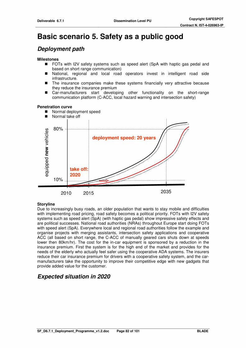
Deliverable 6.7.1 Dissemination Level PU Copyright SAFESPOT
Contract N. IST-4-026963-IP
SF_D6.7.1_Deployment_Programme_v1.2.doc Page 82 of 101 BLADE
Basic scenario 5. Safety as a public good
Deployment path Milestones
� FOTs with I2V safety systems such as speed alert (SpA with haptic gas pedal and based on short range communication)
� National, regional and local road operators invest in intelligent road side infrastructure.
� The insurance companies make these systems financially very attractive because they reduce the insurance premium
� Car-manufacturers start developing other functionality on the short-range communication platform (C-ACC, local hazard warning and intersection safety)
Penetration curve
� Normal deployment speed � Normal take off
Storyline Due to increasingly busy roads, an older population that wants to stay mobile and difficulties with implementing road pricing, road safety becomes a political priority. FOTs with I2V safety systems such as speed alert (SpA) (with haptic gas pedal) show impressive safety effects and are political successes. National road authorities (NRAs) throughout Europe start doing FOTs with speed alert (SpA). Everywhere local and regional road authorities follow the example and organise projects with merging assistants, intersection safety applications and cooperative ACC (all based on short range, the C-ACC of manually geared cars shuts down at speeds lower then 80km/hr). The cost for the in-car equipment is sponsored by a reduction in the insurance premium. First the system is for the high end of the market and provides for the needs of the elderly who actually feel safer using the cooperative ADA systems. The insurers reduce their car insurance premium for drivers with a cooperative safety system, and the car-manufacturers take the opportunity to improve their competitive edge with new gadgets that provide added value for the customer.
Expected situation in 2020
deployment speed: 20 years
take off: 2020
20352010
equip
pe
d n
ew
vehic
les 80%
10%
2015

Deliverable 6.7.1 Dissemination Level PU Copyright SAFESPOT
Contract N. IST-4-026963-IP
SF_D6.7.1_Deployment_Programme_v1.2.doc Page 83 of 101 BLADE
V2IV2V
SAFESPOT platform public lead
private leadgeneric platform
SAFETY AS A PUBLIC GOOD
� The platform consists of short range road side communication infrastructure and
simple on-board units (both built in and nomadic) equipped with short range communication which bring the centralized services into the vehicles. Services that are to be provided are Speed Alert (SpA), Intersection Safety (IRIS), Hazard and Incident Warning(H&IW)
� Road authorities pay the infrastructure from tax money and road users get a reduction on the cost of their insurance premium if they get an in-car safety system. (Safespot business model 4)
� BCR > 1 from year 2042 (V2I bundle functionality) � Penetration complete fleet: about 5 %

Deliverable 6.7.1 Dissemination Level PU Copyright SAFESPOT
Contract N. IST-4-026963-IP
SF_D6.7.1_Deployment_Programme_v1.2.doc Page 84 of 101 BLADE
Basic scenario 6. Extended traffic management Deployment path Milestones
� To stay in control of traffic management, road authorities invest in intelligent road side systems to provide traffic information, speed alert (SpA), Local Hazard Warnings (H&IW), traffic safety (IRIS), recommended speed for green light, and other services (possibly combined with road pricing, and subsidized on-board units)
� Providers of road side infrastructure, navigation providers and car manufacturers all start providing (nomadic or factory fit) on-board units, to bring these services to the road users.
� Alliances between the stakeholders will enable the integration of information services, (active) safety services and comfort services into one in-car system with on interface.
Penetration curve
� Normal deployment speed � Early take off, because the infrastructure is available from 2015, a minimum service
level is provided. This stimulates the early market-introduction for in-car systems.
Storyline Road authorities try to meet their traffic management responsibilities. Therefore they need to stay in control of the traffic flows. They need to deal with the increasing network management power of the large navigation system providers with huge markets shares. In the battle for access to the driver they provide speed alert and in-car traffic signs, through an intelligent road-side communication infrastructure and regulate the in-car platform functionalities. In this scenario, providers of road side equipment also have a leading role. Siemens and Peek have communication equipment installed on signalling installations (VRIs) to enable bus priority. With local governments these road side equipment providers agree to open up these communicating traffic lights for communicating with all traffic. Vehicles communicating with signalling installations enable optimisation on throughput. This is why local government/road operators subsidize investments in the communication infrastructure. Siemens and Peek offer low budget aftermarket in-car systems that enable drivers to get priority at intersections, combined with an intersection safety warning application and in-car traffic signs. Extra applications are developed on these in-car systems, starting with an intersection safety application and speed alert. Car manufacturers offer active driver support systems using the short range services provided at e.g. intersections. or combined with road pricing: Road pricing is rolled out nationally to control congestion in several European countries. The system could be based on long range communication and short range communication and paid from its own revenues. To compensate for this politically unpopular and expensive system and to create synergy, the ministry of transport tenders additional services on the road pricing platform, e.g. local hazard warning. Initially long range communication enables only warning systems that allow latency of the GPRS technology (1.5-3.5 sec), more specifically Speed Alert and Local Hazard Warning. Later car manufacturers take part in the tenders too.
deployment speed: 20 years
take off: 2015
20352010
equip
pe
d n
ew
vehic
les 80%
10%
2015

Deliverable 6.7.1 Dissemination Level PU Copyright SAFESPOT
Contract N. IST-4-026963-IP
SF_D6.7.1_Deployment_Programme_v1.2.doc Page 85 of 101 BLADE
They can provide automatic ADA systems such as ACC. These ADAs could perform better if the communication delay is reduced. Therefore new vehicles are also equipped with short range communication. Initially the short range in-car applications are supported by short range infrastructure repeaters, in order to overcome the limited penetration of vehicles with short range communication.
Expected situation in 2020
EXTENDED TRAFFICMANAGEMENT
V2IV2V
SAFESPOT platform public lead
private leadgeneric platform
� The platform consists of intelligent road side infrastructure (service centre) and on-board units, using both long range and short range communication, which provide multiple services ranging from road pricing, green waves with speed advice, Speed Alert (SpA), Intersection Safety (IRIS) to Hazard and Incident Warning (H&IW).
� Road authorities pay for both the infrastructure and the on-board units (Safespot business model 8). This is paid from increased toll.
� BCR > 1 from year 2031 (V2I bundle) � Penetration complete fleet: about 16%

Deliverable 6.7.1 Dissemination Level PU Copyright SAFESPOT
Contract N. IST-4-026963-IP
SF_D6.7.1_Deployment_Programme_v1.2.doc Page 86 of 101 BLADE
Basic scenario 7. Safety for sale, in the end Deployment path Milestones
� Commercial road operators offer safety services like speed alert (SpA), In-car Traffic Signs and Local Hazard warning (H&IW) based on their (short range) automatic toll collection platform.
� Road user equipped with an (after market) OBU pay less toll and can therefore earn back their investment in the OBU.
� Car manufacturers and navigation providers offer OBUs that support the service provided by the commercial road operators, and also have added value on non-toll roads.
Penetration curve
� low deployment speed; because the system is expensive � late take off 2020; because the market potential for safety application alone is limited
Storyline In this scenario, the private road operators have a leading role. Short range vehicle to infrastructure based communication (802.11p) becomes the leading system configuration for private road operators to collect their revenues. Commercial road operators need to earn back their investments in the infrastructure, so they differentiate in price between equipped vehicles and non-equipped vehicles. Next to the safety incentive, this creates a financial incentive for road users to buy an in-car system which can make use of the infrastructure service. Both car-manufacturers start offering in-car systems as well as aftermarket in-car systems become available.
Expected situation in 2020
V2IV2V
SAFESPOT platform
Safety for sale
in the end
public lead
private leadgeneric platform
low deployment speed:
>30 years
take off:
2020
20352010
eq
uip
pe
d n
ew
ve
hic
les 80%
10%
2015

Deliverable 6.7.1 Dissemination Level PU Copyright SAFESPOT
Contract N. IST-4-026963-IP
SF_D6.7.1_Deployment_Programme_v1.2.doc Page 87 of 101 BLADE
� The platform consists of intelligent road side infrastructure and on-board units, short range communication, for the time critical safety services Hazard & Incident Warning (H&IW) and Speed Alert (SpA).
� Road users pay a subscription fee and a fixed price for the on-board unit (Safespot business model 5)
� BCR < 1 until after 2050 (SpA) � Penetration complete fleet: <2 %

Deliverable 6.7.1 Dissemination Level PU Copyright SAFESPOT
Contract N. IST-4-026963-IP
SF_D6.7.1_Deployment_Programme_v1.2.doc Page 88 of 101 BLADE
Basic scenario 8. Nomadic storm Deployment path Milestones
� Navigation providers provide in-car systems with services like RTTI, speed alert (SpA), local hazard warning (HI&W) and in-car traffic signs based on cellular networks (e.g. GPRS), centralised intelligence and light OBUs
� Navigation providers and car-manufacturers start to cooperate to provide in-car systems with a better performance that enable active driving assistance system
Penetration curve
� Normal deployment speed � Early take off (± 2015), because the cooperation between navigation service
providers and car manufacturers speeds up the introduction of cooperative system.
Storyline Navigation providers provide in-car systems with services like RTTI, speed alert (SpA), local hazard warning (HI&W) and in-car traffic signs, based on cellular networks (e.g. GPRS), based on a road side service centre and relatively simple OBUs that only receive warnings. The services are not time critical and can be provided with long range cellular communication technology (GPRS). To offer more time critical warnings, for instance for vehicles entering a queue (Hazard and Incident Warning – H&IW) or an intersection (Co-operative Intersection Collision Prevention – IRIS), short range communication is provided through a commercially owned infrastructure, e.g. by an internet provider who exploits WiFi hot spots. As a response the in-car application providers (who are now more than just navigation providers) start offering in-car systems that support the short range I2V communication standard based on 802.11p. These time critical warnings provided by the road authorities enable the in-car part of time critical warning systems to be developed. The added value of these warning systems is however much bigger if the warnings are used by automatic driver assistance applications. However, the upgraded navigation system providers do not have access to the can-bus/brak-, steer- or gas-control. Car manufacturers do, and they start to offer ADA applications based on I2V like braking assistance, intersection safety applications. Competition between consortia of the traditional navigation system providers and car manufactures result in competing I2V communication standards, but all cars can hear the messages from the extended and intelligent infrastructure. In exchange they also provide FCD to the infrastructure.
Assumptions - The platform, on which cooperative systems will be provided, will support both short
range (WiFi/802.11p) and long range (GPRS/cellular networks) communication technologies.
- The additional installation of 802.11p communication technology in the government owned infrastructure results in:
o better performance of the existing services Speed Alert (SpA) and Hazard & Incident Warning (H&IW)ADAS
deployment speed: 20 years
take off: 2015
20352010
equ
ippe
d n
ew
vehic
les 80%
10%
2015

Deliverable 6.7.1 Dissemination Level PU Copyright SAFESPOT
Contract N. IST-4-026963-IP
SF_D6.7.1_Deployment_Programme_v1.2.doc Page 89 of 101 BLADE
o and enables more time critical V2I services like Co-operative Intersection Collision Prevention (IRIS)
- The social costs of the additional installation of 802.11p communication technology are less than the social benefits of the increased performance and functionality of the system
- The navigation system providers can make a business case by offering additional traffic management/information services. Both based on long range communication technology (which is already in place in recent navigation systems) and short range communication technology. (The additional costs of installing short range communication technology 802.11p is estimated to be around € 36 per vehicle (source: SP 6.5 Cost estimation workshop)
Expected situation in 2020
� Platform of intelligent road side infrastructure (service centre) and on-board units, using both long range and short range communication, which provide multiple entertainment services, navigation, Speed Alert (SpA), Intersection Safety (IRIS) and Hazard and Incident Warning(H&IW).
� Drivers pay a service fee and buy an on-board unit (Safespot business model 10 ) � BCR > 1 from year 2031 (SpA functionality) � Penetration complete fleet: about 5%
V2IV2V
in-car platform
SAFESPOT platform
NOMADIC STORM
public lead
private lead

Deliverable 6.7.1 Dissemination Level PU Copyright SAFESPOT
Contract N. IST-4-026963-IP
SF_D6.7.1_Deployment_Programme_v1.2.doc Page 90 of 101 BLADE
Annex 3. Selection of the scenarios In the next step three scenarios are selected from the spectrum of eight to elaborate in more detail. ‘Only’ three scnearios are selected because this is considered the maximum number of scenarios that people can reason with. The selection of the three scenarios is based on three criteria. The criteria for the selection are the distribution of the three scenarios over the spectrum of scenarios, the likelihood of the scenarios and if the scenarios describe illustrative deployment challenges.
The three selected scenarios are "technology pushed ITS revolution", "safety as a public good" and "extended traffic management” (Figure 6)
V2IV2V
SAFESPOT platform public lead
private leadmulti-service platform
EXTENDED
TRAFFICMANAGEMENTTECHNOLOGY
PUSHED
ITS REVOLUTION
SAFETY AS A
PUBLIC GOOD
Figure 24: Selected scenarios
The selection is done in three steps. To reduce the number of combinations of well distributed scenarios with interesting deployment challenges, the first step is to identify the most likely scenarios. This resulted in four most likely scenarios. Then the distribution over the spectrum and the deployment challenges are compared. The scenario of the four most likely scnenarios that was not dropped is the “We want safety!” scenario, because it is more likely to follow one of the other scnearios. Therefore it is less illustrative to elaborate it as a single scenario. However, the selection is not a mathematical exercise that has one best answer. Several sensible combinations of three likely and interesting scenarios are possible. The selection procedure is just a means to structure this (arbitrary) choice and provide insight into the considerations.
Step 1: likelihood
The exploratory scenarios are possible images of the future. Some of these scenarios are more likely then others. The likelihood is based on arguments from interviews with stakeholders from the main stakeholder groups and an expert session from TNO during the definition of the mini scenarios (see appendix 1 for the arguments and likelihood score). The likelihood is expressed in +, ++, +++.
Four scenarios are considered more likely then others (+++). These four are represented in the spectrum in Figure 24: Selected scenarios. The most important arguments are that

Deliverable 6.7.1 Dissemination Level PU Copyright SAFESPOT
Contract N. IST-4-026963-IP
SF_D6.7.1_Deployment_Programme_v1.2.doc Page 91 of 101 BLADE
‘Safety alone will never be a driver for deployment’
‘An infrastructure based on short range communication is too costly for private lead’
V2IV2V
SAFESPOT platform public lead
private leadmulti-service platform
EXTENDED
TRAFFICMANAGEMENTTECHNOLOGY
PUSHED
ITS REVOLUTION
SAFETY AS A
PUBLIC GOOD
WE WANTSAFETY!
Figure 25: most likely scenarios
Step 2: Distribution over the spectrum
To obtain a selection of three scenarios that is well distributed over the spectrum, both ends of the scenario dimensions have to be represented in at least one of the scenarios. This means that at least one of the three scenarios describes a public lead, and at least one describes a private lead, at least one a dedicated Safespot platform, and at least one a generic platform, at least one a vehicle-to-vehicle configuration and at least one a vehicle-to-infrastructure configuration. The three most likely scenarios are distributed over the scenario dimensions as required.
Table 6: Likelihood of the deployment scenarios
scenario Likelihood
"You shall all be safe!" +
"Societal quantity discount" ++
"We want safety!" +++
"Technology pushed ITS revolution" +++
"Safety as a public good" +++
"Extended traffic management" +++
"Safety for sale in the end" +
"Nomadic storm" ++

Deliverable 6.7.1 Dissemination Level PU Copyright SAFESPOT
Contract N. IST-4-026963-IP
SF_D6.7.1_Deployment_Programme_v1.2.doc Page 92 of 101 BLADE
An interesting observation about the distribution is that scenarios with a higher likelihood score are public V2I scenarios and private V2V scenarios. This indicates a correlation that V2V corresponds with private lead and V2I with public lead.
Step 3: Interesting deployment challenges
The third step is to compare the expected deployment challenges of the selections. These expectations about the deployment challenges are a rough first impression based on the basic scenarios.
The scenarios that are most likely (+++) show the following interesting deployment challenges:
The scenarios “technology pushed ITS revolution" and provides insight in the respective challenges for navigation providers and car industry to cooperate and how a multi service platform can contribute to the challenge of reaching a minimum penetration level.
The scenario "safety as a public good" ,and the challenges for road authorities to use FOTs to prove the benefits of cooperative safety systems, increase political support and reduce political risks in a step by step deployment path.
The scenario “Extended traffic management” will provide a closer view on the cooperation between public and private stakeholders.
The scenarios with a likely score of ++, which are not in the selection and will therefore not be addressed in the deployment programme, show the following interesting deployment challenges:
The scenario “We want safety!” will give insight into the feasibility for car manufacturers to realize cooperative safety systems and overcome the problem of minimum penetration. This is partly addressed in the “technology pushed ITS revolution”.
The scenario "Nomadic storm" will give insight into the challenges for navigation providers and car industry to cooperate. The cooperation between public and private stakeholders is interesting and different from the other scenarios and is therefore preferred.
The scenario “societal quantity discount” will give insight into the political difficulties of uniting the stakeholders to realise a multi service platform.
These deployment challenges will not be addressed in the deployment programme.
Deliverable 6.7.1 Dissemination Level PU Copyright SAFESPOT
Contract N. IST-4-026963-IP
SF_D6.7.1_Deployment_Programme_v1.2.doc Page 93 of 101 BLADE
Annex 4. Likelihood of the deployment scenarios For each scenario the arguments about the likelihood of the scenarios are listed that were mentioned during a session with TNO experts and interviews with main stakeholders. A likelihood score is assigned to each scenario based on these arguments. The likelihood is expressed in +, ++, +++. Scenario 1. You shall all be safe! Likelihood: +
• ‘Safety alone will never be a driver for deployment’
• ‘The political risk of making cooperative systems mandatory is too high for the European Commission. This can only happen when the E.C. follow an industry wide accepted standard.’ (like ABS, ESC)
• ‘Government lead and a V2V oriented SAFESPOT system do not logically go together’
• ‘Reduction of government subsidies at a penetration of 10% is too early for V2V’
• ‘This is an interesting scenario for governments because they can minimize their own investments’
• ‘Little opportunities for offering other services like information services.’
• ‘Industry is against because higher price cars’
• ‘Governments will only interfere if the market does not function’
• ‘Realisation of European legislation in 5 years rather early. This is only reasonable when the political pressure is very high.’
Scenario 2. Societal quantity discount Likelihood: ++
• ‘Good opportunities for the industry to get a role in the deployment’
• ‘Reaching a minimum penetration is a problem’
• ‘Systems with both safety benefits and throughput and environmental benefits, e.g. C-ACC, would be a more realistic option to be promoted by governments. Making systems mandatory for throughput reasons is however not common.’
• ‘The step from a V2I platform to a short range V2V system is a technically difficult’ Scenario 3. We want safety! Likelihood: +++
• ‘Minimum required penetration will be an issue to start cooperative systems’
• ‘Consolidation in the car industry (take-overs lead to a few major car-manufacturers) could help to reach minimum penetration’
• ‘Just safety applications are not realistic. They will be combined with environment and comfort/throughput systems’
• ‘Realistic scenario if you start in a different corner of the scenario base/three dimensional scenario space.’
• ‘Safety alone will never be a driver for deployment, however, the car industry sees ADAS as an opportunity to distinguish themselves and win customers’
• ‘Represents only a transitional scenario because it should move more quickly to the "technology pushed ITS revolution".’
• ‘This scenario is already going on. Car industry is developing a standard for car2car communication that is being approved by ETSI and CEN’
Scenario 4. Technology pushed ITS revolution Likelihood: +++
• ‘Transition from nomadic devices towards build-in devices is required’ ‘This is already happening; TomTom is being built into Renaults.’
• ‘Market for navigation systems becomes saturated. There are two possibilities for navigation providers to increase their market. 1)Extending to the public domain (RTTI, speed alert), 2) Extending to the private domain (ADA, TomTom/Renault)’
• ‘The platform of nomadic devices facilitates the deployment of safety applications. Due to the high penetration, the platform works as a catalyst.’

Deliverable 6.7.1 Dissemination Level PU Copyright SAFESPOT
Contract N. IST-4-026963-IP
SF_D6.7.1_Deployment_Programme_v1.2.doc Page 94 of 101 BLADE
• ‘If drivers pay for the in-vehicle units additional services are needed to increase acceptance/ market penetration’
Scenario 5. Safety as a public good Likelihood: +++
• ‘Road authorities try to stay in control of the traffic network applying more intelligent means of traffic management’
• ‘Governments are willing to invest in efficient traffic management systems if the market does not provide these’.
• ‘Safety alone will never be a driver for deployment’
• ‘The insurance companies will only reduce insurance premiums if there is statistical evidence of the effects of the system, and a viable business case for them.’
Scenario 6. Extended traffic management Likelihood: +++
• ‘Road pricing fits very well in this scenario, although this depends on the national context’
• ‘This scenario could migrate towards V2V applications’
• ‘Until 2020 V2I is most feasible and therefore most interesting’
• ‘Market for navigation systems becomes saturated. There are two possibilities for navigation providers to increase their market. 1)Extending to the public domain (RTTI, speed alert), 2) Extending to the private domain (ADA, TomTom/Renault)’
Scenario 7. Safety for sale, in the end Likelihood: +
• ‘Safety alone will never be a driver for deployment’
• ‘A privately owned infrastructure based on short range communication is too costly’
• ‘The elderly are a growing potential market for Safety systems. However they are usually not technology minded.’
• ‘If drivers pay for the in-vehicle units additional services are needed to increase acceptance/ market penetration’
Scenario 8. Nomadic storm Likelihood: ++
• ‘Market for navigation systems becomes saturated. There are two possibilities for navigation providers to increase their market. 1)Extending to the public domain (RTTI, speed alert), 2) Extending to the private domain (ADA, TomTom/Renault)’
• ‘Press announcement by Toyota: Toyota follows the development of the navigation providers concerning HMIs’
• ‘A stakeholder group (being the navigation system providers) outside of the current car industry initializes this development’
• ‘If safety alone is provided via V2I at least partly public financing is needed for sufficient market penetration’

Deliverable 6.7.1 Dissemination Level PU Copyright SAFESPOT
Contract N. IST-4-026963-IP
SF_D6.7.1_Deployment_Programme_v1.2.doc Page 95 of 101 BLADE
Annex 5. BLADE applications (D6.5.1, chapter 3) This appendix is chapter three from SAFESPOT BLADE deliverable 6.5.1 Assessment & Evaluation. It described the applications that are selected by the BLADE team as representative examples of SAFESPOT applications.
Deliverable 6.7.1 Dissemination Level PU Copyright SAFESPOT
Contract N. IST-4-026963-IP
SF_D6.7.1_Deployment_Programme_v1.2.doc Page 96 of 101 BLADE

Deliverable 6.7.1 Dissemination Level PU Copyright SAFESPOT
Contract N. IST-4-026963-IP
SF_D6.7.1_Deployment_Programme_v1.2.doc Page 97 of 101 BLADE

Deliverable 6.7.1 Dissemination Level PU Copyright SAFESPOT
Contract N. IST-4-026963-IP
SF_D6.7.1_Deployment_Programme_v1.2.doc Page 98 of 101 BLADE

Deliverable 6.7.1 Dissemination Level PU Copyright SAFESPOT
Contract N. IST-4-026963-IP
SF_D6.7.1_Deployment_Programme_v1.2.doc Page 99 of 101 BLADE

Deliverable 6.7.1 Dissemination Level PU Copyright SAFESPOT
Contract N. IST-4-026963-IP
SF_D6.7.1_Deployment_Programme_v1.2.doc Page 100 of 101 BLADE
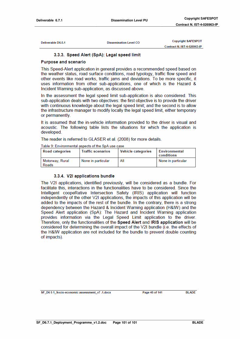
Deliverable 6.7.1 Dissemination Level PU Copyright SAFESPOT
Contract N. IST-4-026963-IP
SF_D6.7.1_Deployment_Programme_v1.2.doc Page 101 of 101 BLADE