Sewer Robotics - idehkavan-tech.com · Sewer Robotics Alireza Ahrary Graduate School of...
27
17 Sewer Robotics Alireza Ahrary Graduate School of Information, Production and Systems, Waseda University Japan 1. Introduction The usage of tethered, remotely controlled robot platforms in sewer pipes has become widely accepted. Research and development in engineering have moved the original application field of merely visual inspection to manipulative tasks such as the actual repair of pipe sections, installation of cable, e.g. for communication. Despite all engineering advances in the mechanical design of the platforms and improvements of the video equipment, these efforts are directed to increase the quality of the data provided to the human operator. Yet the potential for automatic processing and data analysis in combination with hardware platform, as well as the application of IT technology for the development of an integrated sewer information system is neglected. In this chapter, we being with the introduction of the legal framework together with the present inspection method, in which environment sewer inspection is embedded. Further, we will point out critical issues involved with the present inspection method. Sewer systems are prone to damages due to aging, traffic, geological change, to name a few. Due to these damages, the groundwater is increasingly contaminated. Furthermore, heavy rainfall events may lead to inroad of the systems, resulting in overflow. In the case of separate sewer system as widely present in Japan (Table 1), this results in the undesired mixture of wastewater and rainwater. Thus, in order to ensure an optimal functioning sewer system, extensive inspection is necessary. Preceding repair is extensive qualified diagnostic measurement. Tethered mobile robots used for visual inspection in municipal and industrial sewer networks are one example. Beyond this classic task of application of the tethered robot as an extended tool of the human operator, new fields have emerged. Due to ongoing research and development of the mechanical design, tethered robots are now able to perform repair tasks with varying degree of complexity. Other emerging fields of application are the installation of communication cable in the sewer system as well as the encasement of inner pipe walls during renovation or repair. (Most of the materials presented in this chapter have been selected from the material provided by “Steinbeis Japan Inc., Kitakyushu Foundation for the Advancement on Industry, Science and Technology,” March 2002.) separate sewer (sanitary sewer) separate sewer (rainwater) combined sewer 73% 5% 22% Table 1. Division of sewer system in Japan www.intechopen.com
Transcript of Sewer Robotics - idehkavan-tech.com · Sewer Robotics Alireza Ahrary Graduate School of...
17
Sewer Robotics
Alireza Ahrary Graduate School of Information, Production and Systems, Waseda University
Japan
1. Introduction
The usage of tethered, remotely controlled robot platforms in sewer pipes has become widely accepted. Research and development in engineering have moved the original application field of merely visual inspection to manipulative tasks such as the actual repair of pipe sections, installation of cable, e.g. for communication. Despite all engineering advances in the mechanical design of the platforms and
improvements of the video equipment, these efforts are directed to increase the quality of
the data provided to the human operator. Yet the potential for automatic processing and
data analysis in combination with hardware platform, as well as the application of IT
technology for the development of an integrated sewer information system is neglected.
In this chapter, we being with the introduction of the legal framework together with the present inspection method, in which environment sewer inspection is embedded. Further, we will point out critical issues involved with the present inspection method. Sewer systems are prone to damages due to aging, traffic, geological change, to name a few.
Due to these damages, the groundwater is increasingly contaminated. Furthermore, heavy
rainfall events may lead to inroad of the systems, resulting in overflow. In the case of
separate sewer system as widely present in Japan (Table 1), this results in the undesired
mixture of wastewater and rainwater. Thus, in order to ensure an optimal functioning sewer
system, extensive inspection is necessary. Preceding repair is extensive qualified diagnostic
measurement. Tethered mobile robots used for visual inspection in municipal and industrial
sewer networks are one example. Beyond this classic task of application of the tethered
robot as an extended tool of the human operator, new fields have emerged. Due to ongoing
research and development of the mechanical design, tethered robots are now able to
perform repair tasks with varying degree of complexity. Other emerging fields of
application are the installation of communication cable in the sewer system as well as the
encasement of inner pipe walls during renovation or repair.
(Most of the materials presented in this chapter have been selected from the material provided by “Steinbeis Japan Inc., Kitakyushu Foundation for the Advancement on Industry, Science and Technology,” March 2002.)
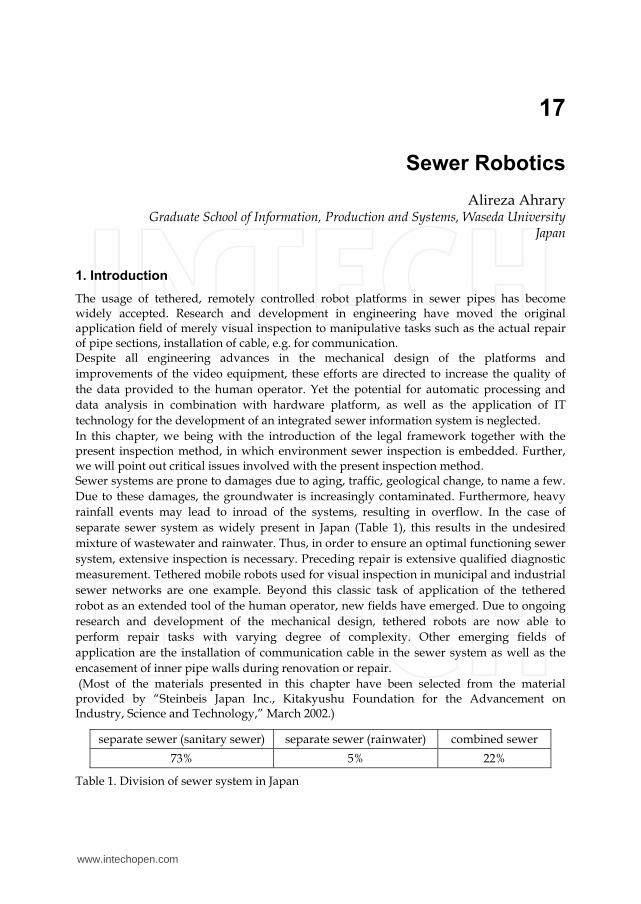
separate sewer (sanitary sewer) separate sewer (rainwater) combined sewer
73% 5% 22%
Table 1. Division of sewer system in Japan
www.intechopen.com

Service Robot Applications
284
In Japan, matters regarding sewer pipes are regulated by the Sewer Water Law. The municipal governments as owners of the facilities are responsible for installation and maintenance of the public sewer system. In practice, authorities such as the construction bureau will authorize local companies to conduct inspections and after deciding upon the necessity also outsource the repair. Although inspection cycles are clearly defined and also governed in the sewer system book, in reality, inspections are done after the occurrence of noticeable damages. Due to limitations in budget and equipment, the given inspection intervals are not strictly adhered to. This can also be clearly seen by comparison of actual inspected distance, 77km (Table 2) with total length of applicable sewer pipes, 3,220,053m (Table 3), for the financial year 2000. This gives us a ration of 0.0017%.
Year 1996 1997 1998 1999 2000 2001 2002
Length (m) 46,374 45,103 59,786 52,922 53,956 53,019 77,711
Table 2. Inspected sewer length per year at Kitakyushu city, Japan
We have to distinguish between two different types of inspection. For sewer pipe systems with an inner diameter larger than 800mm, human inspection is possible and conducted. The above mentioned tethered robot inspection platforms are used for pipes with a diameter less than 800mm.
Diameter (mm) Length (m)
0 18,692
150 210,424
200 2,074,502
250 329,528
300 144,505
350 81,914
380 18,099
400 64,869
450 61,921
480 102
500 65,141
600 85,373
700 64,983
Sum (m) 3,220,053
Table 3. Present condition of sewer pipe length (diameter < 800mm) at Kitakyushu city, Japan (financial year 2000).
Both inspection procedures common is the acquisition of damages by the human inspector, either on loci or by means of video equipment. Based on the above information, manual inspection is done at maximum 77km/year which would take more than 40 years to complete all of the 3220km of pipes in Kitakyushu. In additional, reliability of the current
www.intechopen.com

Sewer Robotics
285
inspection method is depends on experience of an operator and it is also prone to human error. Accordingly, an effective autonomous robot capable of online identification and extraction of objects of interest such as cracks from sensory signals is of immediate concern. To realize an autonomous system with capability of the pipe inspection, several companies and institutes in the world put efforts and researches at building of the robots with the different qualitative degrees of autonomy. In general the degree of autonomy in developed inspection pipe robots is classified as follow:
• No autonomy: The robot is completely tele-operated, usually via a tether cable, by a human operator. The pipe condition is assessed by the human operator who watches the sensor data (usually video) as the robot drives through the pipe. Mostly all the commercial sewer inspection robots are not autonomous system.
• Semi-autonomy: The tethered robot (in a few cases un-tethered) is partially controlled by automatic control programs or modules, or the assessment of the pipe condition is partially performed by sensor data interpretation programs.
• Full autonomy: The un-tethered robot carries all required resources onboard. Navigation is performed completely by control programs running on onboard computing equipment. Status messages may be communicated to a human inspector over a radio link. Assessment of the pipe condition may be performed partially onboard, or offline after retrieval of the recorded sensory data.
In general, we observe that fully autonomous robots are not yet marketable systems today. There are two main reasons for this:
• The degree of development of complete autonomous sewer robots does presently not warrant to use them safely and robustly in sewers. As mentioned in above, most of these robots have a complex moving mechanism and multi-sensor equipment for navigation and motion control. These complexities in mechanism and data processing make not easy to realize reliable commercial products especially for small range of the pipes up to 300mm in diameter.
• There seems to be some general skepticism about using fully autonomous systems without a possibility to interfere the robot control at any time, as would be the case for a tether-less sewer robot out of the range of some radio link.
However, semi-autonomy does make sense, implementing in a tele-operated sewer robot
separate modules (like special sensors with data interpretation software, or special motion
control modules) that operate autonomously within the overall control of a human operator.
The purpose of such embedded autonomous modules would be to leverage the work load of
the human operator in controlling the robot and interpreting sensor data, or to make certain
measurements like in sewer inspection automatic, and therefore operational and
reproducible. This is a serious issue in ensuring the quality of sewer maintenance, given that
the pressure to provide service as cheap as possible imperils the quality of the inspection
results.
In consequence, it makes sense in a mid-term market-oriented R&D strategy in sewer robotics to consider even those autonomous systems or components that do not seem to be sufficiently far developed for the market now, but may include separate or separable components that may have a mid-term market impact. The systems and approaches reviewed in the following are to be understood in that sense. On the long run, fully autonomous systems may become a reality in sewer maintenance, but it seems difficult now to predict a time line for this to happen.
www.intechopen.com

Service Robot Applications
286
2. Conventional sewer robots
2.1 PIRAT
PIRAT (Pipe Inspection Real-Time Assessment Technique) is a semi autonomous tethered robot for the quantitative and automatic assessment of sewer condition (Kirkham et al., 1999). The PIRAT sewer inspection system has been developed between 1993 and 1996 within a joint project of the Manufacturing Systems and Automation Division of Australian CSIRO Manufacturing Science and Technology and Melbourne Water. Just like a conventional sewer inspection device, PIRAT (Fig. 1) is deployed to a sewer, and tele-operated from a surveillance unit via a cable by a human operator. The maximum cable length of 250m gives PIRAT a fair operating range. The added value of the PIRAT system is its ability to perform automatic evaluation of its sensory data. PIRAT’s innovative instrument system contains a video camera and a laser scanner. For flooded sewers, the latter can be substituted by a sonar scanner, but at the price of less resolution and inspection speed. In 600mm sewer pipes and at PIRAT’s usual inspection speed, the laser scanner produced a resolution of about 1.5mm radially and 4mm axially and circumferentially. The sensory data are evaluated by means of PIRAT’s interpretation system, which is an expert system that runs on a Sun workstation in the mobile surveillance unit. From both types of scanner data, the interpretation system generated in a first step a three-dimensional model of the scanned sewer pipe section. In a second step, the interpretation system uses techniques from artificial intelligence to detect and classify damages on the basis of the three-dimensional model data. The result is a sewer condition assessment report that is readable for the human operator.
Fig. 1. The automated video inspection platform, PIRAT (http://vision.cmit.csiro.au/project/pirat/)
2.2 KARO
KARO (KAnalROboter - German for sewer robot) is an experimental semi autonomous carrier for sewer inspection sensory equipment (Kuntze & Haffner, 1998), (Kuntze et al, 1995). It was developed by a group of research institutes and some industrial partners in Germany. The project was partly funded by the German Ministry for Research and Education (BMBF). The monolithic KARO robot prototype (see Fig. 2) resembles much a standard non-autonomous sewer inspection robot, and it is tethered via a cable to a surveillance unit. Using inclinometers and an onboard control program, KARO is able to automatically correct
www.intechopen.com
Sewer Robotics
287
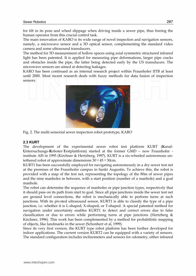
for tilt in its pose and wheel slippage when driving inside a sewer pipe, thus freeing the human operator from this crucial control task. The main innovation of KARO is its wide range of novel inspection and navigation sensors, namely, a microwave sensor and a 3D optical sensor, complementing the standard video camera and some ultrasound transducers. The method for 3D measurement of hollow spaces using axial symmetric structured infrared light has been patented. It is applied for measuring pipe deformations, larger pipe cracks and obstacles inside the pipe, the latter being detected early by the US transducers. The microwave sensors are aimed at detecting leakages. KARO has been continued as an internal research project within Fraunhofer IITB at least until 2000. Most recent research deals with fuzzy methods for data fusion of inspection sensors.
Fig. 2. The multi sensorial sewer inspection robot prototype, KARO
2.3 KURT
The development of the experimental sewer robot test platform KURT (Kanal- Untersuchungs-Roboter-Testplattform) started at the former GMD – now Fraunhofer - institute AIS in 1995 (Kirchner & Hertzberg, 1997). KURT is a six-wheeled autonomous un-
tethered robot of approximate dimensions 30×45×30cm. KURT1 has been successfully employed for navigating autonomously in a dry sewer test net at the premises of the Fraunhofer campus in Sankt Augustin. To achieve this, the robot is provided with a map of the test net, representing the topology of the 80m of sewer pipes and the nine manholes in between, with a start position (number of a manhole) and a goal manhole. The robot can determine the sequence of manholes or pipe junction types, respectively that it should pass on its path from start to goal. Since all pipe junctions inside the sewer test net are ground level connections, the robot is mechanically able to perform turns at such junctions. With its pivoted ultrasound sensor, KURT1 is able to classify the type of a pipe junction, i.e. whether it is L-shaped, X-shaped, or T-shaped. A special patented method for navigation under uncertainty enables KURT1 to detect and correct errors due to false classification or due to errors while performing turns at pipe junctions (Hertzberg & Kirchner, 1996). This work has been complemented by a method for probabilistic mapping of objects, like landmarks in the sewer (Schonherr et al, 1999). Since its very first version, the KURT type robot platform has been further developed for indoor applications. The current version KURT2 can be equipped with a variety of sensors. The standard configuration includes inclinometers and sensors for odometry, either infrared
www.intechopen.com

Service Robot Applications
288
or ultrasound distance transducers for obstacle detection, and optional bumpers. Fig. 3 shows a KURT2 system with a custom mounted 2D laser distance scanner and a notebook computer “Tough book” as CPU. Alternatively, an industry standard PC/104+ CPU can be provided.
Fig. 3. The commercial research robot platform, KURT2
2.4 MAKRO
MAKRO (Mehrsegmentiger Autonomer KanalROboter/multi-segmented autonomous sewer robot) is the prototype of a fully autonomous, un-tethered, self-steering articulated robot platform (Fig. 4). It is designed for autonomous navigation in roughly cleaned sewer pipes within a diameter range of 300 to 600mm at dry weather conditions.
Fig. 4. Automated inspection platform, MAKRO
MAKRO’s case design, consisting of six segments connected by five motor driven active joints, allows for simultaneously climbing a step and turning, e.g. at a junction consisting of a 600mm pipe and a branching 300mm pipe with equal top levels. MAKRO’s autonomy and its kinematic abilities extend its potential mission range enormously, compared to conventional inspection equipment that is limited by the cable and poor kinematics (Rome et al, 1999). MAKRO carries all the needed resources onboard. Standard NiCd batteries provide the power for its 21 motors, the sensors, and the electronics, including an industry standard
www.intechopen.com

Sewer Robotics
289
PC104 computer system and seven micro controllers (Kepplin et al, 1999), allowing for an autonomous uptime of about two hours. The robot MAKRO has been developed by a German group of two research institutes and two industrial partners. The MAKRO project was funded partly by the German Ministry for Research and Education (BMBF) between 1997 and 2000. Since 2001, the MAKRO project is being continued as internal projects at Fraunhofer AIS and FZI (Scholl et al, 2000).
3. Sewer sensors
In this section, we review innovative sensors and sensor interpretation methods for sewer maintenance. The range of the depicted sensors ranges from widely applicable sensors such as compasses for navigation, to general usage sensor such as laser scanners up to especially for the application in sewer system developed ground penetrating sensors. Besides sensor systems, innovative methods of sewer maintenance, states of sewer pipes are of interest. The fusion of these innovative sensors and application methods will ensure that not only exhibited damage in the pipe in a narrow sense like a leak or crack or a blockage, but are potential heralds of a growing damage, like a bent or twisted pipe segment are successfully identified.
3.1 Laser scanners
Laser scanners are a technology that is in broad use in autonomous robots in general. Originally, they were developed as security sensors for surveying free space in production processes (such as protected areas around dangerous machines). For indoor applications, they are available in many different varieties at a highly developed technological level. The general principle is to measure by run-time of a laser beam the distance from a laser source to target objects. In scanners, the laser beam is deflected at different angles, measuring distances along a plane or half-plane, depending on the rotation and form of the deflecting mirror. The accuracy of the individual measurements is in the order of 1mm, depending on the measuring device and the distance. The application principle for sewer inspection is to mount the scanner such that it scans radially the inner side of a pipe wall, see Fig. 5. If the inspection device moves along the pipe while measuring, the laser beam measures along a spiral on the pipe inside, where the resolution of the spiral depends on the turn rate of the reflection mirror and the speed of horizontal motion of the inspection device, typical turn rates being 1-2 turns per second.
Fig. 5. OMC pipe profiler (City University of London) measured distances (red) overlayed with the circle (blue) that would represent the ideal pipe inside (profile image by Hytec)
www.intechopen.com

Service Robot Applications
290
As a result, a model of the pipe geometry can be directly acquired, which makes possible to
detect deformations within the accuracy and resolution of the measurement principle.
Recently, prototypes of such sewer laser scanners have become available on the market. We
mention two such systems here. Due to the precision and simplicity of the measurement
principle and due to the simplicity of data interpretation, we expect laser scanners to
become important sensors on fully autonomous or semi-autonomous sewer inspection
robots.
-Hytec
The company Hytec (Montpellier, France) has developed a rotating laser, which performs
exact measurement of the pipe’s shape. It operates in pipelines of with 200 to 1000mm. The
software for deflection calculation is included; the measured pipe profile can be viewed in
real time on a PC color monitor. The VSLPC laser systems come as integrated with a color
TV camera.
-Optimess
The company Optimess (Gera, Germany) offers the laser scanner OptiScan, originally
developed by MFPA in Weimar, Germany (Kampfer et al, 1998). The variant OptiScan200
(Fig. 6) operates in pipes from 200mm, at a measuring distance of 5-100cm and an accuracy
of ±1mm (according to vendor). Again, the software for calculating and visualizing the
measured profile are available.
Fig. 6. OptiScan
3.2 Radar-like sensors
Ground Penetrating Radar (GPR) systems are in general heavy and power consuming. The
antenna systems are large with respect to the dimension of a pipe robot.
A first use of GPR with a sewer system was announced by the developers of the KARO.
They developed a GPR small enough for a sewer system. They also used a micro wave
device to inspect anomalies behind the pipe walls. They report that it is possible to
distinguish from type of sources of different anomalies based on bubbles of air or water,
pipe couplings and house connections.
Commercially available system is presented by Oyo and Burn Am. In the case of Oyo, no
data in regard to the applicability of this tool is available (i.e. do the number and severity of
hidden cavities balance the expense of the radar).
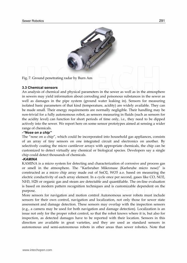
In contrast, Burn Am has developed the Ground Penetrating Radar Sensor to marketable
stage. The present model is integrated to a tethered, remotely controlled platform, Fig. 7.
www.intechopen.com
Sewer Robotics
291
Fig. 7. Ground penetrating radar by Burn Am
3.3 Chemical sensors
An analysis of chemical and physical parameters in the sewer as well as in the atmosphere
in sewers may yield information about corroding and poisonous substances in the sewer as
well as damages in the pipe system (ground water leaking in). Sensors for measuring
isolated basic parameters of that kind (temperature, acidity) are widely available. They can
be made small. Their energy requirements are normally negligible. Their handling may be
non-trivial for a fully autonomous robot, as sensors measuring in fluids (such as sensors for
the acidity level) can function for short periods of time only, i.e., they need to be dipped
actively into the sewer. We report here on some sensor prototypes aimed at sensing a wider
range of chemicals.
-“Nose on a chip”
The “nose on a chip”, which could be incorporated into household gas appliances, consists
of an array of tiny sensors on one integrated circuit and electronics on another. By
selectively coating the micro cantilever arrays with appropriate chemicals, the chip can be
customized to detect virtually any chemical or biological species. Developers say a single
chip could detect thousands of chemicals.
-KAMINA
KAMINA is a micro system for detecting and characterization of corrosive and process gas
or smell in the atmosphere. The “Karlsruher Mikronase (Karlsruhe micro nose)” is
constructed as a micro chip array made out of SnO2, WO3 a.o. based on measuring the
electric conductivity of each array element. In a cycle once per second, gases like CO, NO2,
NH3, H2S or organic gas and steam are detectable and quantifiable. The on-line evaluation
is based on modern pattern recognition techniques and is customizable dependent on the
purpose.
More sensors for navigation and motion control Autonomous sewer robots must include
sensors for their own control, navigation and localization, not only those for sewer state
assessment and damage detection. These sensors may overlap with the inspection sensors
(e.g., a camera may be used for both navigation and damage detection). Localization is an
issue not only for the proper robot control, so that the robot knows where it is, but also for
inspection, as detected damages have to be reported with their location. Sensors in this
direction are available in great varieties, and they are used as standard sensors in
autonomous and semi-autonomous robots in other areas than sewer robotics. Note that
www.intechopen.com
Service Robot Applications
292
sewer robots have the requirements in addition driver-less indoor transportation vehicles
that their sensors be physically small and energy efficient.
-Compass
For navigation purposes it is helpful to know the northern direction. Accordingly, a
compass may be of help. Electronic compasses are widely available on the market. Note that
compass readings may be noisy in a sewer robot due to the many objects of city
infrastructure that can typically be found close to sewers (steel constructions, cables, etc.).
Therefore, among available electronic compasses, only those should be used on a sewer
robot that report possible disturbances of their readings.
-Inertial sensors • Inclination sensors Essential for helping to control tilt in fully autonomous or semiautonomous platforms. They are in use, e.g., in the KURT, MAKRO and KARO systems reported elsewhere in this thesis. They are widely available on the market, fitting the space and energy requirements of a sewer robot.
• Accelerometers Essential for helping the localization and control of fully autonomous robots.
• Gyroscopes Essential for measuring turns in autonomous robots. Widely available, but highly precise sensors are costly and may be large in build. All gyroscopes suffer from a systematical error of drift over time caused by the earth rotation.
4. Conventional inspection methods
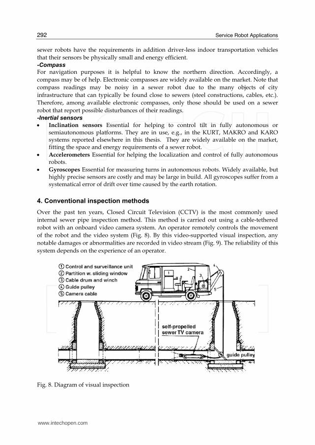
Over the past ten years, Closed Circuit Television (CCTV) is the most commonly used
internal sewer pipe inspection method. This method is carried out using a cable-tethered
robot with an onboard video camera system. An operator remotely controls the movement
of the robot and the video system (Fig. 8). By this video-supported visual inspection, any
notable damages or abnormalities are recorded in video stream (Fig. 9). The reliability of this
system depends on the experience of an operator.
Fig. 8. Diagram of visual inspection
www.intechopen.com

Sewer Robotics
293
Fig. 9. Operator with video monitor
Recently, new and more accurate techniques have been fielded to conduct internal sewer pipe assessments. The methods used for inspecting pipe condition, fall into three broad categories:
• Inspection of inner pipe surface
• Inspection of pipe structure and bedding conditions
• Inspection of the pipe bedding The first category, with which most practicing engineers are most familiar, included CCTV (conventional, light line and computer assisted), laser scanning and ultrasound techniques. The second and third categories include micro deflection, impact echo and ground-penetrating techniques to assess the conditions of the pipe outer layer and surrounding soil. The cost and accuracy of these methods vary widely and some methods are only justified in very specific situations where other methods will not produce an acceptable quality of information. Other inspection methods may be combined with CCTV inspection to verify the pipe condition assessment (Thomas & Laszczynski, 1997). These methods may include soils testing, physical and chemical testing of removed pipe segments (Biery et al, 1998).
5. Methods of inspecting the inner sewer wall surface
5.1 CCTV inspection systems
Standard pipe inspection systems are based on Closed Circuit Television (CCTV) cameras in a large range of application fields such as waste pipes and drains. The CCTV method consists of a mobile, remotely operated platform usually equipped with a color, high-resolution video camera and a lighting system. The camera platform is connected via a multi-core cable to a remote inspection station with video recording facilities situated over ground. An engineer then assesses the recorded images off-line. There are two basic types of the CCTV system. Each uses a television camera in conjunction
with a video monitor, video cassette recorders and possibly other recording devices. In one
case the inspection is performed using a stationary or zoom camera mounted at a manhole
so that it looks into the sewer, while in the other a mobile, robotic system is placed within
the sewer itself. Either form of CCTV inspection may miss certain types of defects, especially
those that are hidden from the camera by obstructions as it looks down the sewer. Slight
deformations of the sewer may go unnoticed, and any defects hidden beneath water inside
the sewer will definitely not be found.
www.intechopen.com

Service Robot Applications
294
This is a subjective and time-consuming task that considerably increases the inspection costs. Moreover, only gross anomalies are evident to the human eye, which reduces the detection of faults at early stages. Another drawback associated with those systems in these particular environments is the lack of visibility inside the pipes and the poor quality of the acquired images that hinders a complete assessment of the pipe condition and sometimes even the detection of large defects.
5.2 Stationary CCTV systems
Stationary video cameras mounted at a manhole are limited with respect to what they can
see. Defects that are close to the manhole will be found, but the farther into the sewer a
defect is, the harder it will be to identify and evaluate. Defects beyond the range of the
camera would be missed entirely unless they cause secondary effects that can be identified
at the manhole (such as changes in water flow within the pipe between two manholes). One
vendor of this technology suggests that the equipment be used as part of a screening process
to determine which sewer sections should be completely examined by mobile CCTV
systems. Stationary CCTV’s usefulness in this respect will depend on whether the damage
that can be detected by this type of system near a manhole in a sewer line is representative
of that throughout the entire section of sewer line.
A survey of defects by IRC (Makar, 1999) indicates that, based on structural factors alone, stationary CCTV can readily be used to inspect vitrified clay sewers. In brick sewers the most efficient use of stationary CCTV would be to restrict it to inspecting sewer lines that are shorter than 50 meters in length, although a slightly greater factor of safety in the inspections would be produced by using the technique only on pipe sections that are less than 40 meters in length. While the results suggest that concrete pipes may be inspected in the same manner as vitrified clay pipes, too few concrete pipes were examined for a definitive conclusion to be reached.
5.3 Mobile CCTV systems
Mobile CCTV systems are the most common means of inspecting sewer lines. This type of CCTV system uses a camera mounted on a robot that enters the sewer system. The camera generally looks forward as the robot system moves along the sewer axis, allowing the operator to examine and evaluate the entire length between a pair of manholes. It is possible to modify this type of CCTV system to overcome many of the limitations of CCTV inspection discussed above. Some CCTV systems have “pan and tilt” cameras attached to the robot, which can find defects hidden from a forward looking camera behind connections and other obstructions within the sewer line. Sonar or ultrasound systems are often attached to robots to examine the sewer below the waterline. It is also possible to obtain CCTV equipment with a“light line”attachment to assist in quantifying smaller sewer deformations. This system projects a line of light around the circumference of the sewer being examined in order to assist in assessing the shape of the sewer. Inspecting within the pipe wall and the bedding condition Although CCTV, laser and ultrasonic systems provide images of the inside surface of a pipe wall, they do not indicate what is happening within the pipe wall or behind it. While in some cases the observed damage to a pipe is due to internal problems such as erosion, in many others the damage is caused by external forces. The following inspection techniques allow the sewer owner to examine the overall condition of an entire pipe wall, the soil behind a pipe or the pipe-soil system. Their ability to look beyond a pipe
www.intechopen.com

Sewer Robotics
295
wall surface gives sewer owners opportunities to evaluate sewer condition in ways that are not possible with CCTV and similar techniques.
5.4 Wall micro-deflections and natural frequency of vibration
Measurements of wall micro-deflections and the natural frequencies of vibration of sewer lines are being developed specifically as a means of diagnosing brick sewer condition. The methods give information on the overall mechanical condition of the sewer line, rather than identifying specific defects. A micro deflection in a pipe wall surface is created by applying pressure to the inside surface of the wall to very slightly deform it. In this case the intent is to measure the change in position versus the increase in pressure applied to the wall in order to indicate how well the grout between the bricks has been applied or whether the walls of a concrete or brick pipe have been damaged. It would be expected that a well grouted brick wall would expand continuously (although not equally) in all directions as the pressure increases, provided the pressure is below that which would damage the grouting. A similar, equal increase would be seen in an undamaged concrete or vitrified clay pipe. Increasing in micro deflection in one direction while decreasing in another or a sudden
change in the slope of a graph of applied force versus micro deflection would suggest that
the wall was damaged. The major difficulty with this technique is determining the
maximum safe pressure for use on a brick wall so that the inspection method does not
damage it. This pressure will depend on the pre-existing condition of the sewer. While these
pressures can be readily calculated for an undamaged sewer, the accuracy of such
calculations is dependent on knowledge of the strength of the mortar or concrete at any
given point in the sewer. This will vary depending on the age and condition of each sewer
section. Care must therefore be taken to avoid damaging sewer sections that have below
normal strength but are still able to function properly. This safety consideration is not as
important for concrete pipes, where the strength of the pipe material is more uniform
around the pipe circumference. Micro deflections are restricted in use to rigid pipes where
an entire pipe wall will be deflected by the applied force.
Plastics such as PVC and HDPE can not be inspected using this method as local deformation
of the pipe wall would tend to provide a false indication of the pipe condition. The
restriction of the technique to materials such as brick, concrete, metal and vitrified clay
means that it is only sensitive to the wall condition, rather than that of the surrounding
bedding. Measuring the natural frequency of vibration also gives information about the
mechanical behavior of a pipe wall, but in this case the process involves vibrating the wall at
a range of frequencies and determining which frequency gives the largest vibrations (the
natural frequencies). A section of good wall would be expected to have certain characteristic
natural frequencies, while deviations from those frequencies would indicate that the wall or
surrounding bedding was deficient in some manner. The application of this technique
depends on the development of an understanding of exactly how the natural frequencies of
different types of pipe wall would be expected to change with increasing damage. However,
other factors can also affect the results of the natural frequency measurement, including
changes in bedding material or quality, the amount of water in the pipe and the height of
ground water around the pipe. Considerable research is needed to determine if these effects
can be separated from those produced by actual damage to the pipe wall.
www.intechopen.com

Service Robot Applications
296
5.5 Impact echo/spectral analysis of surface waves
These closely related techniques they have been successfully applied to the inspection of large, empty concrete pipes and large brick water lines. The SEKISUI Company has made a sewer inspection robot with a hammer and microphone. The apparatus consists of a source of controlled impacts, such as a falling weight or a large pneumatic hammer and one or more geo phones that are mounted against the wall of the pipeline. Low frequency surface waves are produced when the wall of the pipe is struck by the hammer or weight. These waves are then detected by the geo phones. The major difference between the two techniques is that impact echo generally looks only at the actual waveform produced by the impact, while spectral analysis of surface waves (SASW) uses more geo phones and separates the waves into different frequency components (Opara et al, 1996). These different components travel at different speeds and penetrate to different depths in the soil beyond the pipe, allowing more information to be gathered about the condition of the pipe and surrounding soil. Although the two techniques are similar, the use of the additional sensors and analysis in SASW means that it is possible to easily separate effects produced by soil conditions from those produced by problems in the pipe wall. SASW therefore is the most flexible of all the techniques discussed in this section since it is capable of investigating both pipe wall and soil condition at the same time. A drawback of Impact Echo and SASW inspection is that they are currently only available for manual use in large diameter tunnels that are easily accessible by human operators. Both techniques need to be automated to increase their inspection rate and allow deployment in smaller diameter pipelines. A second drawback is that cleaning of the pipe walls is likely to be required before they can be used. Detecting conditions behind the pipe wall although some of the inspection techniques described previously can give information about conditions behind a pipe wall, their primary use is likely to be in determining the structural soundness of the wall itself. By contrast, ground penetrating radar may occasionally give information about delaminating in concrete sewers, but its major use in sewer lines is in detected potential problems behind the sewer walls.
5.6 Ground penetrating radar
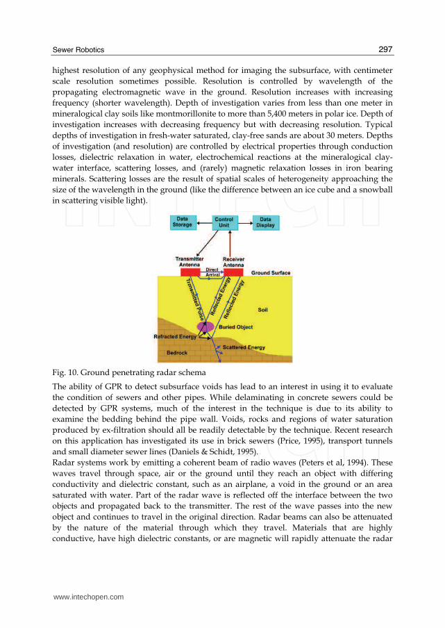
Ground Penetrating Radar (GPR) is a geophysical method that has been developed over the past thirty years for shallow, high-resolution, subsurface investigations of the earth. GPR uses high frequency pulsed electromagnetic waves (generally 10 MHz to 1,000 MHz) to acquire subsurface information. Energy is propagated downward into the ground and is reflected back to the surface from boundaries at which there are electrical property contrasts, Fig. 10 shows a diagram of the process. GPR is a method that is commonly used for environmental, engineering, archaeological, and other shallow investigations. Radar is well known for its ability to detect airplanes or other flying objects, but with
significant adaptations it can also penetrate rocks, sand and other solid materials to detect
buried objects and voids. GPR is widely used in locating lost utilities, environmental site
characterization and monitoring, agriculture, archaeological and forensic investigation,
unexploded ordnance and land mine detection, groundwater, pavement and infrastructure
characterization, mining, ice sounding, permafrost, void, cave and tunnel detection,
sinkholes, subsidence, etc. It may be deployed from the surface by hand or vehicle. It has the
www.intechopen.com
Sewer Robotics
297
highest resolution of any geophysical method for imaging the subsurface, with centimeter
scale resolution sometimes possible. Resolution is controlled by wavelength of the
propagating electromagnetic wave in the ground. Resolution increases with increasing
frequency (shorter wavelength). Depth of investigation varies from less than one meter in
mineralogical clay soils like montmorillonite to more than 5,400 meters in polar ice. Depth of
investigation increases with decreasing frequency but with decreasing resolution. Typical
depths of investigation in fresh-water saturated, clay-free sands are about 30 meters. Depths
of investigation (and resolution) are controlled by electrical properties through conduction
losses, dielectric relaxation in water, electrochemical reactions at the mineralogical clay-
water interface, scattering losses, and (rarely) magnetic relaxation losses in iron bearing
minerals. Scattering losses are the result of spatial scales of heterogeneity approaching the
size of the wavelength in the ground (like the difference between an ice cube and a snowball
in scattering visible light).
Fig. 10. Ground penetrating radar schema
The ability of GPR to detect subsurface voids has lead to an interest in using it to evaluate
the condition of sewers and other pipes. While delaminating in concrete sewers could be
detected by GPR systems, much of the interest in the technique is due to its ability to
examine the bedding behind the pipe wall. Voids, rocks and regions of water saturation
produced by ex-filtration should all be readily detectable by the technique. Recent research
on this application has investigated its use in brick sewers (Price, 1995), transport tunnels
and small diameter sewer lines (Daniels & Schidt, 1995).
Radar systems work by emitting a coherent beam of radio waves (Peters et al, 1994). These
waves travel through space, air or the ground until they reach an object with differing
conductivity and dielectric constant, such as an airplane, a void in the ground or an area
saturated with water. Part of the radar wave is reflected off the interface between the two
objects and propagated back to the transmitter. The rest of the wave passes into the new
object and continues to travel in the original direction. Radar beams can also be attenuated
by the nature of the material through which they travel. Materials that are highly
conductive, have high dielectric constants, or are magnetic will rapidly attenuate the radar
www.intechopen.com

Service Robot Applications
298
beam. As a result radar is attenuated very rapidly in metals, giving essentially zero
penetration, but can travel very long distances in air and space.
Sand, asphalt, clay and ice fall between these two extremes, with the degree of attenuation
dependant on amount of liquid water and salts present in the material. Ice is essentially
transparent to GPR, allowing the technique to be used to map the bottoms of glaciers. It can
also penetrate deeply in dry sand. However, the depth of penetration in wet sand is much
less, and in clays the penetration is further reduced (Benson, 1995). In these materials the
presence of water increases the conductivity, while clays can also have significant dielectric
constants. The presence of salt in the ground increases the soil conductivity and therefore
further decreases the maximum penetration depth of a GPR system.
Radar can be used to locate leaks in buried water pipes either by detecting voids in the soil
created by leaking water as it circulates near the pipe, or by detecting segments of pipe
which appear deeper than they are because of the increase in the dielectric constant of
adjacent soil saturated by leaking water. Ground penetrating radar waves are partially
reflected back to the ground surface when they encounter an anomaly in dielectric
properties, for example, a void or pipe. An image of the size and shape of the object is
formed by radar time-traces obtained by scanning the ground surface. The time lag between
transmitted and reflected radar waves determines the depth of the reflecting object.
In sewer pipes application, a radar antenna moves inside the sewer and is cable connected
to a recording unit above ground. GPR may be used to detect water leaks in two ways:
• Identifying soil cavities created by the turbulent flow of leaking water.
• Identifying pipe segments, which appear deeper than expected because of the increase of the dielectric constant of adjacent soil, saturated by leaking water.
Despite a number of problems GPR has been employed in the condition assessment process
for sewer lines in France since the early eighties. Data inspection requires substantial
experience and training because the radar output is very difficult to interpret.
These techniques may be used from either the ground surface or from within the pipe but
does not provide specific information on the pipe wall condition. For above ground use the
technique is used to either identify the presence of pipe segments or the presence of voids
surrounding the pipe, both by measuring the changing dielectric of the soil, cavities and
pipes. For within pipe use the technique is used to identify cavities in the soil behind the
pipe wall. In traditional above ground penetrating radar techniques, both transmitting and
recording devices are mounted on the ground surface above the pipe.
6. Difficulties in conventional systems
The conventional inspection systems used for inspecting pipe condition in three broad
categories are described in section 4. Among them, we focus on inspection of inner pipe
surface and discuss about the difficulties in conventional systems.
Each of the systems for inspecting the inner surface of the pipe wall provides similar types
of information to the manager of a sewer system. Conventional CCTV’s long history of use
means that new systems inspecting the same area must provide substantial advantages in
the quality of information provided or in lower costs before they will be adopted for
common use. Table 4 summarizes the advantages and disadvantages of each inspection
methods.
www.intechopen.com

Sewer Robotics
299
Methods Advantage Disadvantage
CCTV inspection
systems
• Standard technique.
• Considerable body of knowledge.
• Available to aid in interpreting results.
• Relatively cheap.
• Evaluates the entire length of sewer.
• Substantial operator interpretation of results.
• Difficult to accurately compare two evaluations of the same sewer conducted at different times.
• May miss defects hidden behind obstructions or under water.
Stationary CCTV
systems
• Cheaper than CCTV.
• Possibly useful as a screening mechanism for other techniques.
in addition to those listed for CCTV;
• Only examines the sewer near manholes.
• Long brick sewers are likely to be incorrectly.
• Classified as undamaged.
Mobile CCTV
systems
As for conventional CCTV except;
• Better estimation of sewer deformation.
As for conventional CCTV except;
• Greater expense than conventional CCTV.
Table 4. Summarizes the advantages and disadvantages of conventional inspection methods
The described modifications to conventional CCTV can assist in interpreting the results of a CCTV inspection, but are unlikely to be widely adopted unless their cost is not significantly higher than that of conventional CCTV alone. Stationary CCTV cameras are therefore the most likely application to enter common use, as they offer the opportunity to do preliminary examinations of the shorter pipes in a city’s sewer system without cleaning. Mobile CCTV systems offer noticeable advantages in identifying the presence of deformation, but are essentially an evolutionary enhancement of the standard CCTV system, rather than a revolutionary improvement.
7. Fully autonomous sewer robot, “KANTARO”
Hereafter, we describe an innovative method for realization of the fully autonomous sewer pipe inspection to cover the above mentioned problem. We improved the complexities of navigation for the motion control based on multi-sensor equipment by definition and implementation of intelligent module architecture for KANTARO (Ahrary et al, 2007), (Nassiraei et al, 2007). KANTARO is the prototype of a passive-active intelligent, fully autonomous, un-tethered robot which has an intelligent architecture in its sensor and mechanism. KANTARO, including a novel passive-active intelligent moving mechanism, is able to move into the straight pipe and passes different kinds of pipe bends without need to any intelligence of the controller or sensor reading. In addition to realize a fully autonomous inspection robot, we developed a small and intelligent 2D laser scanner for detecting of the navigational landmarks such as manholes and inlets (Ahrary et al, 2006) as stand-alone system and fusion with a fish eye camera to assist the pipe state and fault detection.. Consequently, we purpose a fully autonomous sewer inspection system but with a possibility to interfere the KANTARO control as it drives through the pipe either via an
www.intechopen.com

Service Robot Applications
300
optical underground wireless communication module, developed in this project, or via a life optic un-tethered cable.
7.1 KANTARO architecture
KANTARO is designed as a fully autonomous, un-tethered robot, which fits to the pipes within a diameter range of 200-300mm. KANTARO’s autonomy and its kinematic abilities extend its potential mission range enormously, comparing to conventional inspection equipment that is limited by the cable and poor kinematics. KANTARO carries all the necessary resources onboard. Standard lithium polymer batteries provide the power for its 4 motors, the sensors, the light and electronics, including a developed computer system and an optical underground wireless communication module, allowing for an autonomous uptime of about one hour. To realize a reliable, robust robot and an easy maintenance system, KANTARO is designed to have a complete modular architecture in its mechanic, hardware and software. KANTARO, as shown in (Fig. 11), consists of two main modules: Bottom and Upper box modules. Bottom box, including a passive-active intelligent mechanism and a battery pack, can be presented as a robot platform. Electronic boards, the sensors and light are installed in upper box which be connected via the main connector to the bottom box. In addition, KANTARO has IP67 waterproof standard that it achieved by waterproof design of KANTARO’s modules including the upper and bottom box, motor boxes and battery pack.
Fig. 11. KANTARO has a modular architecture consist of two main modules: Bottom box and Upper box. Modularity of bottom and upper boxes showed in right and left of the figure, consequently.
www.intechopen.com
Sewer Robotics
301
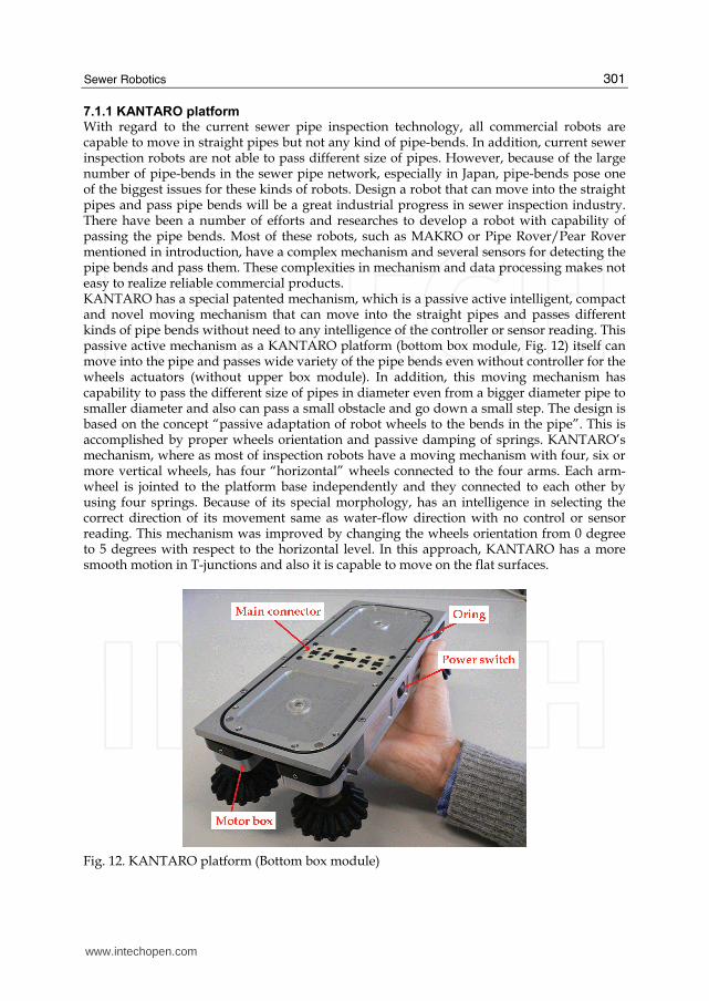
7.1.1 KANTARO platform With regard to the current sewer pipe inspection technology, all commercial robots are capable to move in straight pipes but not any kind of pipe-bends. In addition, current sewer inspection robots are not able to pass different size of pipes. However, because of the large number of pipe-bends in the sewer pipe network, especially in Japan, pipe-bends pose one of the biggest issues for these kinds of robots. Design a robot that can move into the straight pipes and pass pipe bends will be a great industrial progress in sewer inspection industry. There have been a number of efforts and researches to develop a robot with capability of passing the pipe bends. Most of these robots, such as MAKRO or Pipe Rover/Pear Rover mentioned in introduction, have a complex mechanism and several sensors for detecting the pipe bends and pass them. These complexities in mechanism and data processing makes not easy to realize reliable commercial products. KANTARO has a special patented mechanism, which is a passive active intelligent, compact and novel moving mechanism that can move into the straight pipes and passes different kinds of pipe bends without need to any intelligence of the controller or sensor reading. This passive active mechanism as a KANTARO platform (bottom box module, Fig. 12) itself can move into the pipe and passes wide variety of the pipe bends even without controller for the wheels actuators (without upper box module). In addition, this moving mechanism has capability to pass the different size of pipes in diameter even from a bigger diameter pipe to smaller diameter and also can pass a small obstacle and go down a small step. The design is based on the concept “passive adaptation of robot wheels to the bends in the pipe”. This is accomplished by proper wheels orientation and passive damping of springs. KANTARO’s mechanism, where as most of inspection robots have a moving mechanism with four, six or more vertical wheels, has four “horizontal” wheels connected to the four arms. Each arm-wheel is jointed to the platform base independently and they connected to each other by using four springs. Because of its special morphology, has an intelligence in selecting the correct direction of its movement same as water-flow direction with no control or sensor reading. This mechanism was improved by changing the wheels orientation from 0 degree to 5 degrees with respect to the horizontal level. In this approach, KANTARO has a more smooth motion in T-junctions and also it is capable to move on the flat surfaces.
Fig. 12. KANTARO platform (Bottom box module)
www.intechopen.com
Service Robot Applications
302
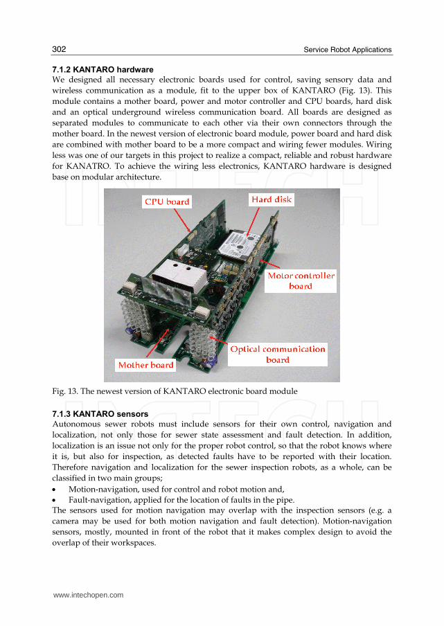
7.1.2 KANTARO hardware
We designed all necessary electronic boards used for control, saving sensory data and
wireless communication as a module, fit to the upper box of KANTARO (Fig. 13). This
module contains a mother board, power and motor controller and CPU boards, hard disk
and an optical underground wireless communication board. All boards are designed as
separated modules to communicate to each other via their own connectors through the
mother board. In the newest version of electronic board module, power board and hard disk
are combined with mother board to be a more compact and wiring fewer modules. Wiring
less was one of our targets in this project to realize a compact, reliable and robust hardware
for KANATRO. To achieve the wiring less electronics, KANTARO hardware is designed
base on modular architecture.
Fig. 13. The newest version of KANTARO electronic board module
7.1.3 KANTARO sensors
Autonomous sewer robots must include sensors for their own control, navigation and
localization, not only those for sewer state assessment and fault detection. In addition,
localization is an issue not only for the proper robot control, so that the robot knows where
it is, but also for inspection, as detected faults have to be reported with their location.
Therefore navigation and localization for the sewer inspection robots, as a whole, can be
classified in two main groups;
• Motion-navigation, used for control and robot motion and,
• Fault-navigation, applied for the location of faults in the pipe. The sensors used for motion navigation may overlap with the inspection sensors (e.g. a
camera may be used for both motion navigation and fault detection). Motion-navigation
sensors, mostly, mounted in front of the robot that it makes complex design to avoid the
overlap of their workspaces.
www.intechopen.com
Sewer Robotics
303
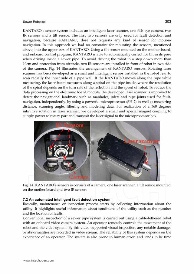
KANTARO’s sensor system includes an intelligent laser scanner, one fish eye camera, two
IR sensors and a tilt sensor. The first two sensors are only used for fault detection and
navigation, because KANTARO, dose not requests any kind of sensor for motion-
navigation. In this approach we had no constraint for mounting the sensors, mentioned
above, into the upper box of KANTARO. Using a tilt sensor mounted on the mother board,
and onboard control program, KANTARO is able to automatically correct for tilt in its pose
when driving inside a sewer pipe. To avoid driving the robot in a step down more than
10cm and protection from obstacle, two IR sensors are installed in front of robot in two side
of the camera. Fig. 14 illustrates the arrangement of KANTARO sensors. Rotating laser
scanner has been developed as a small and intelligent sensor installed in the robot rear to
scan radially the inner side of a pipe wall. If the KANTARO moves along the pipe while
measuring, the laser beam measures along a spiral on the pipe inside, where the resolution
of the spiral depends on the turn rate of the reflection and the speed of robot. To reduce the
data processing on the electronic board module, the developed laser scanner is improved to
detect the navigational landmark such as manholes, inlets and pipe joints used for fault-
navigation, independently, by using a powerful microprocessor (SH-2) as well as measuring
distance, scanning angle, filtering and modeling data. For realization of a 360 degrees
infinitive rotation in laser scanner, we developed a small and special magnet coupling to
supply power to rotary part and transmit the laser signal to the microprocessor box.
Fig. 14. KANTARO’s sensors is consists of a camera, one laser scanner, a tilt sensor mounted on the mother board and two IR sensors
7.2 An automated intelligent fault detection system
Basically, maintenance or inspection process starts by collecting information about the
utility. It highlights useful information about conditions of the utility such as the number
and the location of faults.
Conventional inspection of a sewer pipe system is carried out using a cable-tethered robot
with an onboard video camera system. An operator remotely controls the movement of the
robot and the video system. By this video-supported visual inspection, any notable damages
or abnormalities are recorded in video stream. The reliability of this system depends on the
experience of an operator. The system is also prone to human error, and tends to be time
www.intechopen.com

Service Robot Applications
304
consuming and expensive. Consequently, effective automated online techniques to identify
and extract objects of interest such as cracks are of immediate concern.
All previous works focused on specific types of faults in pipes and none of them proposes a
method for detecting various types of faults. Accordingly, an automated fault detection
system is not available in the real world. In this project, we propose a method for detecting
faulty areas based on images, and propose an automated intelligent system designed to
facilitate diagnosis of faulty areas in a sewer pipes system (Ahrary et al, 2007). The system
utilizes image analysis and efficient techniques for providing the location and the number of
faults in a sewer pipe system.
An overview of the automated intelligent fault detection system is shown in Fig.15. Digital
images of sewer pipes taken by the camera system on the inspection robot are given to the
fault detection system. The system, then, extracts a global ring ROI image to which edge
enhancement is applied as preprocessing. Next, a newly defined measure of horizontal
similarity is computed in order to extract candidates for visible faulty area in the ring ROI
areas. Conjecture here is that the measure of similarity between images without faulty area
is large. Hence, we focus on the area where the horizontal similarity value is smaller than a
horizontal threshold, thh, ranged between 0 and 1. Next, we extract a rectangular ROI and
compute the vertical similarity value in the candidate faulty areas. Here, the area with
vertical similarity value smaller than a vertical threshold, thv, is defined as a faulty area. The
proposed approach can detect even faint faults in this rectangular ROI area. Finally the
detected faults and its locations are compiled as a report. Here the location information on
faults is provided by sensors on the robot such as an encoder, IR and a laser scanner.
Fig. 15. An overview of the automated intelligent fault detection system
www.intechopen.com

Sewer Robotics
305
7.3 Experimental results
We evaluate the proposed system and KANTARO with designed GUI in the real sewer pipe
net. The general information of inspection by using proposed system in real sewer pipe net
is shown in Table 5.
Inspection date 2006.1.25 2006.9.20 2006.10.13
Inspection length 32(m) 88(m) 132(m)
Inspection time 10(min) 28(min) 45(min)
Numbers of existing faults 2 cracks 2 cracks 2 cracks+2 root invasions
Number of manholes 2 4 6
Table 5. The general information of inspection by using proposed system in real sewer pipe net
Table 5 shows sewer pipes net of length of 32(m), 88(m) and 132(m) with 2, 4 and 6
manholes is inspected. The inspection time shown here depends on the speed of the robot.
The inspection results are shown in Table 6. Note that the inspected pipe net has been
checked by sewer Inspection Company using the conventional system, therefore the
numbers and locations of existing faults in each area were known in advance. The
inspection results show that all existing faults in sewer pipe net are detected by the
proposed system. Also, for generating a final report, we only need to print the report folder
images (each image has the location, time and marked faulty areas information). We can say
that the proposed system succeeds in attaining high detection performance, time and cost
reduction in sewer inspection. Fig.16 shows scenery of inspection by proposed system in
real sewer pipe net.
Inspection date 2006.1.25 2006.9.20 2006.10.13
Numbers of detected faults 2 2 4
Table 6. The inspection results by using proposed system in real sewer pipe net
Fig. 17. Scenery of inspection in real sewer pipe net by proposed system
www.intechopen.com
Service Robot Applications
306
8. Conclusions and future works
In this chapter we proposed an innovative, fast and robust sewer inspection method by
using a passive active intelligent, fully autonomous, un-tethered robot, called “KANTARO”,
which fits to the pipes within a diameter range of 200-300mm. KANTARO prototype robot,
including a novel passive active intelligent moving mechanism, has a robust movement into
the straight pipe and smooth and rapid motion while passes different kinds of pipe bends
without need of any intelligence of the controller or sensor reading. In this approach
KANTARO does not request any kind of sensor for its motion inside of the pipe.
In addition, we developed a small and intelligent 2D laser scanner for detecting of the
navigational landmarks such as manholes and pipe joints independently with main
computer system and fusion with a fish eye camera, mounted on the KANTARO, used for
assessing the pipe state and fault detection. Realization of KANTARO as a fully
autonomous, reliable and robust pipe inspection robot has been achieved by designing an
architecture based on intelligence at its modules and definition and implementation of a life
optic un-tethered cable to make the inspection process easily and safely. To prove that
KANTARO is able to use as a commercial product, we still have to perform further
experiments in real world sewer pipe network with different in size and state pipe
condition. Improving the offline fault detection software to get high accuracy is on the
future work.
9. References
Ahrary, A.; Kawamura, Y. & Ishikawa, M. (2007). An automated intelligent fault detection
system for inspection of sewer pipes, IEEJ Transactions on Electronics, Information and
Systems, Vol.127, No.6, pp.943-950, June 2007.
Ahrary, A.; Nassiraei, A.F. & Ishikawa, M. (2007). A study of an autonomous mobile robot
for a sewer inspection system, Journal of Artificial Life and Robotics, Vol.11, No.1,
pp.23-27, January 2007.
Ahrary, A.; Kawamura, Y. & Ishikawa, M. (2006). A laser scanner for landmark detection
with the sewer inspection robot KANTARO, Proceedings of the IEEE International
Conference on System of Systems Engineering (ICSoSE'06), pp.310-315, Los Angeles,
USA, April 2006.
Benson, A. (1995). Applications of ground penetrating radar in assessing some geological
hazards: examples of groundwater contamination, faults, cavities, Journal of Applied
Geophysics, Vol.33, No.1, pp.177-193, January 1995.
Biery, J.; Ratliff, A. & Hall, S. (1998). Evaluation of 70-year-old non-reinforced concrete
sewers, Proceedings of Pipeline Division Conference, pp.318-327, San Diego, CA, USA,
August 1998.
Daniels, D. & Schidt, D. (1995). The use of ground probing radar technologies for non-
destructive testing of tubes, Proceedings of the International Symposium of
Nondestructive Testing in Civil Engineering, pp. 429-436, Berlin, Germany, September
1995.
www.intechopen.com
Sewer Robotics
307
Hertzberg, J. & Kirchner, F. (1996). Landmark-based autonomous navigation in sewerage
pipes, Proceedings of First Euromicro Workshop on Advanced Mobile Robots (EUROBOT
‘96), pp. 68-73, Kaiserslautern, Germany, October 1996.
Kampfer, W.; Bartzke, R. & Ziehl, W. (1998). Flexible mobile robot system for smart optical
pipe inspection, Proceedings of SPIE Conference Nondestructive Evaluation of Utilities
and Pipelines II, pp. 75-83, San Antonio, Texas, March 1998.
Kepplin, V.; Scholl, K.U. & Berns, K. (1999). A mechatronic concept for a sewer inspection
robot, Proceedings of IEEE/ASME International Conference on Advanced Intelligent
Mechatronics (AIM ’99), pp. 724-729, Piscataway, NJ, September 1999.
Kirchner, F. & Hertzberg, J. (1997). A prototype study of an autonomous robot platform for
sewerage system maintenance, Autonomous Robots, Vol.4, Issue 4, pp.319-331,
October 1997.
Kirkham, R.; Kearney, P.D. & Rogers, K.J. (2000). PIRAT - A system for quantitative sewer
assessment, The International Journal of Robotics Research, Vol.19, No.11, pp. 1033-
1053, November 2000.
Kuntze, H.B. & Haffner, H. (1998). Experiences with the development of a robot for smart
multisensoricpipe inspection, Proceedings of IEEE International Conference on Robotics
and Automation (ICRA ’98), pp. 1773-1778, Leuven, Belgium, May 1998.
Kuntze, H.B.; Schmidt, D.; Haffner, H. & Loh, M. (1995). KARO - A flexible robot for smart
sensor-based sewer inspection, Proceedings of 12th International No-Dig Conference,
pp. 367-374, Hamburg, September 1995.
Makar, J. M. (1999). Diagnostic techniques for sewer systems, Journal of Infrastructure
Systems, Vol.5, No.2, pp. 69-78, June 1999.
Nassiraei, A.F.; Kawamura, Y.; Ahrary, A.; Mikuriya, Y. & Ishii, K. (2007). Concept and
design of a fully autonomous sewer pipe inspection mobile robot "KANTARO",
Proceedings of the IEEE International Conference on Robotics and Automation (ICRA'07),
pp.136-143, Roma, Italy, April 2007.
Opara, N.K.; Wooda, R.D. & Shayea, N. (1996). Nondestructive testing of concrete structures
using the Rayleigh wave dispersion method, Journal of American Concrete Institute
Materials, Vol.93, No.1, pp. 75-86, January 1996.
Peters, L.; Daniels, J. & Young, J. (1994). Ground penetrating radar as a subsurface
environmental sensing tool, Proceedings of the IEEE International Conference on
Robotics and Automation, Vol.82, pp. 1802-1822, December 1994.
Price, T. (1995). Inspecting buried plastic pipe using a rotating sonic caliper, Proceedings of
the Second International Conference on Advances in Underground Pipeline Engineering,
pp.126-137, Bellevue, Washington, June 1995.
Rome, E.; Hertzberg, j.; Kirchner, F.; Licht, U.; Streich, H. & Christaller, TH. (1999). Towards
autonomous sewer robots: The MAKRO project, Journal of Urban Water, Vol.1, No.1,
pp. 57-70, March 1999.
Schonherr, F.; Hertzberg, J. & Burgard, W. (1999). Probabilistic mapping of unexpected
objects by a mobile robot, Proceedings of the IEEE/RSJ International Conference on
Intelligent Robots and Systems (IROS ’99), vol.1, pp. 474-481, 1999.
Scholl, K.U.; Kepplin, V.; Berns, K. & Dillmann, R. (2000). Controlling a multi-joint robot for
autonomous sewer inspection, Proceedings of IEEE/RAS International Conference on
www.intechopen.com

Service Robot Applications
308
Robotics and Automation (ICRA 2000), pp. 1701-1706, Piscataway (NJ), San Francisco,
April 2000.
Thomas, A. & Laszczynski, G. (1997). New technology for enhanced pipeline evaluation,
Proceedings of the ASCE Conference on Trenchless Pipeline Projects, pp. 291-297, Boston,
MA, USA, June 1997.
www.intechopen.com

Service Robot ApplicationsEdited by Yoshihiko Takahashi
ISBN 978-953-7619-00-8Hard cover, 400 pagesPublisher InTechPublished online 01, August, 2008Published in print edition August, 2008
InTech EuropeUniversity Campus STeP Ri Slavka Krautzeka 83/A 51000 Rijeka, Croatia Phone: +385 (51) 770 447 Fax: +385 (51) 686 166www.intechopen.com
InTech ChinaUnit 405, Office Block, Hotel Equatorial Shanghai No.65, Yan An Road (West), Shanghai, 200040, China
Phone: +86-21-62489820 Fax: +86-21-62489821
The aim of this book is to provide new ideas, original results and practical experiences regarding servicerobotics. This book provides only a small example of this research activity, but it covers a great deal of whathas been done in the field recently. Furthermore, it works as a valuable resource for researchers interested inthis field.
How to referenceIn order to correctly reference this scholarly work, feel free to copy and paste the following:
Alireza Ahrary (2008). Sewer Robotics, Service Robot Applications, Yoshihiko Takahashi (Ed.), ISBN: 978-953-7619-00-8, InTech, Available from:http://www.intechopen.com/books/service_robot_applications/sewer_robotics