Severstal NA C Blast Furnace 2007 Revamping - Equipment Design Transforms C BF Into a World-Class...
11
March 2009 ✦ 65 T he primary challenge faced by the reline team working on revamping Severstal NA “C” blast furnace (C BF) was developing a scope of work that balanced installation of the best available blast furnace equipment and technologies within the duration of the furnace outage. The initial 120-day outage estimate was compressed to a timeline of 100 days. To achieve this reduced schedule, the contractors and equipment suppliers were required to use innovative approaches to the construction and installation of the new fur- nace shell. The project scope was massive and encom- passed the demolition of the old furnace shell down to the concrete foundation, and the removal of the dust catcher and wet gas cleaning plant. A second taphole and new casthouse were installed to improve furnace availability and casting practices. In addition, the scope of work included integrating the existing stockhouse charging controls with the new bell-less top, rebuild- ing of the hot blast stove system, and the construction of a closed-loop recirculating cooling water system with plate heat exchang- ers. A new furnace control room was built with multiple display screens and a PLC-based control system installed for furnace process data acquisition and reporting. Above-burden temperature and gas sampling probes were installed to provide measurement of the blast furnace condition and to provide input data for the process computer models. The revamping work for the furnace and ancillary equipment was completed two days ahead of schedule, allowing the blow-in of the furnace to take place on day 98 of the sched- uled 100 days. Background The steel manufacturing facility at Dearborn, Mich., was originally built in 1917 and was an integral part of the Ford River Rouge Manufacturing complex. Rouge Steel Co. was formed in 1981 as a wholly owned subsidiary of the Ford Motor Co. In 1989, Rouge Steel was sold to a group of investors and became an independent steel producer, Rouge Industrial Inc. On Jan. 30, 2005, OAO Severstal acquired the assets of Rouge Industrial Inc. and formed Severstal North America Inc. (SNA). The highest annual raw steel production of this facility has been 3,099,157 tons in 1998. Since Severstal acquired the assets of Rouge Steel Co., the future of the furnace has undergone a critical review as part of a plan to refurbish the mill facilities to make SNA more competitive. A program to modernize the Rouge Plant facilities was developed. In February 2007, the program was approved by the OAO Severstal board of directors, and the construction began. The modernization projects include upgrades to C BF with an ultimate hot metal production rate of 6,500 net tons per day, construction of a secondary emissions control baghouse at the BOF, straight mold upgrade to the two strand casters, hot mill reheat furnace Severstal NA “C” Blast Furnace 2007 Revamping: Equipment Design Transforms C BF Into a World-Class Operation Severstal North America’s “C” blast furnace underwent a revamping in the fall of 2007. Criteria for decisions on equipment replacement or enhancements are presented and the benefits discussed. Authors Bruce Edwards, general manager — blast furnace technology, Paul Wurth Ltd., Burlington, Ont., Canada ([email protected]); Art Cheng (left), manager — technology, iron production, and Stuart Street (right), process specialist – iron producing, Severstal North America Inc., Dearborn, Mich. ([email protected], [email protected]); Bill Ebner, vice president — engineering, Paul Wurth Inc., Canonsburg, Pa. ([email protected]); and Lionel Hausemer, project engi- neer — engineering, Paul Wurth S.A., Luxembourg, Luxembourg ([email protected])
-
Upload
marcos-carrero -
Category
Documents
-
view
88 -
download
0
Transcript of Severstal NA C Blast Furnace 2007 Revamping - Equipment Design Transforms C BF Into a World-Class...
March 2009 ✦ 65
The primary challenge faced by the reline team working on revamping Severstal
NA “C” blast furnace (C BF) was developing a scope of work that balanced installation of the best available blast furnace equipment and technologies within the duration of the furnace outage. The initial 120-day outage estimate was compressed to a timeline of 100 days. To achieve this reduced schedule, the contractors and equipment suppliers were required to use innovative approaches to the construction and installation of the new fur-nace shell.
The project scope was massive and encom-passed the demolition of the old furnace shell down to the concrete foundation, and the removal of the dust catcher and wet gas cleaning plant. A second taphole and new casthouse were installed to improve furnace availability and casting practices.
In addition, the scope of work included integrating the existing stockhouse charging controls with the new bell-less top, rebuild-ing of the hot blast stove system, and the construction of a closed-loop recirculating cooling water system with plate heat exchang-ers. A new furnace control room was built with multiple display screens and a PLC-based control system installed for furnace process data acquisition and reporting. Above-burden temperature and gas sampling probes were installed to provide measurement of the blast furnace condition and to provide input data for the process computer models.
The revamping work for the furnace and ancillary equipment was completed two days ahead of schedule, allowing the blow-in of the furnace to take place on day 98 of the sched-uled 100 days.
BackgroundThe steel manufacturing facility at Dearborn, Mich., was originally built in 1917 and was an integral part of the Ford River Rouge Manufacturing complex. Rouge Steel Co. was
formed in 1981 as a wholly owned subsidiary of the Ford Motor Co. In 1989, Rouge Steel was sold to a group of investors and became an independent steel producer, Rouge Industrial Inc. On Jan. 30, 2005, OAO Severstal acquired the assets of Rouge Industrial Inc. and formed Severstal North America Inc. (SNA).
The highest annual raw steel production of this facility has been 3,099,157 tons in 1998.
Since Severstal acquired the assets of Rouge Steel Co., the future of the furnace has undergone a critical review as part of a plan to refurbish the mill facilities to make SNA more competitive. A program to modernize the Rouge Plant facilities was developed. In February 2007, the program was approved by the OAO Severstal board of directors, and the construction began.
The modernization projects include upgrades to C BF with an ultimate hot metal production rate of 6,500 net tons per day, construction of a secondary emissions control baghouse at the BOF, straight mold upgrade to the two strand casters, hot mill reheat furnace
Severstal NA “C” Blast Furnace 2007 Revamping:Equipment Design Transforms C BF Into a World-Class Operation
Severstal North America’s “C” blast furnace
underwent a revamping in the fall of 2007. Criteria for
decisions on equipment replacement or enhancements
are presented and the benefits discussed.
Authors
Bruce Edwards, general manager — blast furnace technology, Paul Wurth Ltd., Burlington, Ont., Canada ([email protected]); Art Cheng (left), manager — technology, iron production, and Stuart Street (right), process specialist – iron producing, Severstal North America Inc., Dearborn, Mich. ([email protected], [email protected]); Bill Ebner, vice president — engineering, Paul Wurth Inc., Canonsburg, Pa. ([email protected]); and Lionel Hausemer, project engi-neer — engineering, Paul Wurth S.A., Luxembourg, Luxembourg ([email protected])
66 ✦ Iron & Steel Technology
modernization, a new pickle line connected to a new tandem mill, cold mill improvements, and a new hot-dip galvanizing line.
The modernization program will reduce operating costs and improve product capabil-ity to meet the demands of automotive cus-tomers and other markets. This would then afford SNA a better chance to compete and assure more security for SNA and its employ-ees. The new C BF is a fundamental element of the program and is the cornerstone of the modernization program for SNA.
C Blast Furnace Design HistoryC BF was originally constructed in 1948 and named the William Clay Ford blast furnace. The first iron was produced on Nov. 22, 1948. The furnace was built as an 8-column mantle supported shell with the stack lining cooled by plates. The furnace has been overhauled nine times during its 59-year life, the most recent being in 1991. Since 1948, the blast furnace has been in continuous operation, until July 12, 2007, when the modernization process began with the dismantling of the furnace shell. Only the original eight support columns remained and were incorporated into the design of the new furnace shell.
1991 C BF Reline — C BF had a hearth diameter of 29 feet and a working volume of 53,176 ft.3. The furnace was a single-taphole operation with fixed iron casting positions. The burden charging system was a 2-bell McKee top without a distributor. The rated hot metal production was 4,500 net tons of iron per day.
The 1991 furnace reline installed a com-bined D-grade carbon and 70% alumina brick in the hearth. The tuyere surrounds were built with D-grade carbon. The hearth wall and tuyere breast were constructed using NMA carbon brick. The bosh refractory, NMA car-bon brick, was cooled using water panels. The furnace stack refractory linings were alumina-based brick and cooled with stack plates.
The hot blast system was designed to deliver an aim hot blast temperature of 1,950°F. The natural gas injection system was sized to deliver at a rate of 150–175 pounds per net ton of iron.
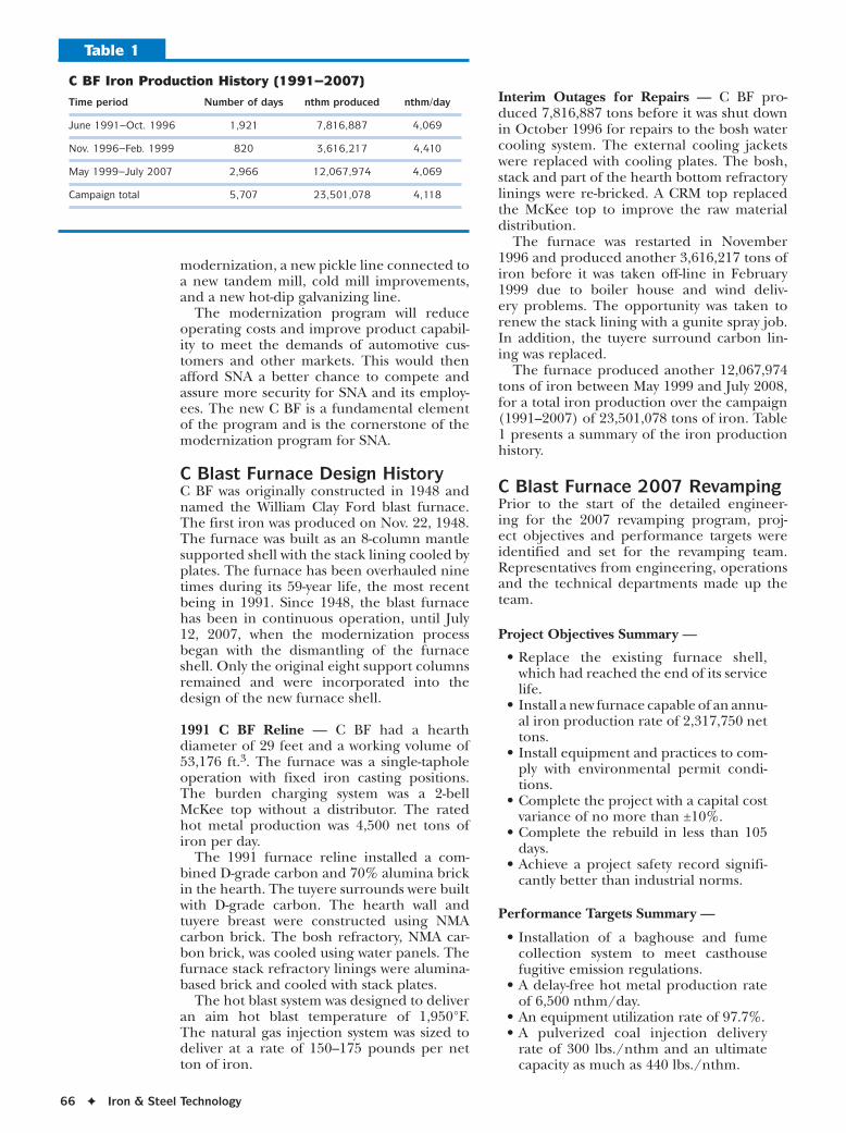
Interim Outages for Repairs — C BF pro-duced 7,816,887 tons before it was shut down in October 1996 for repairs to the bosh water cooling system. The external cooling jackets were replaced with cooling plates. The bosh, stack and part of the hearth bottom refractory linings were re-bricked. A CRM top replaced the McKee top to improve the raw material distribution.
The furnace was restarted in November 1996 and produced another 3,616,217 tons of iron before it was taken off-line in February 1999 due to boiler house and wind deliv-ery problems. The opportunity was taken to renew the stack lining with a gunite spray job. In addition, the tuyere surround carbon lin-ing was replaced.
The furnace produced another 12,067,974 tons of iron between May 1999 and July 2008, for a total iron production over the campaign (1991–2007) of 23,501,078 tons of iron. Table 1 presents a summary of the iron production history.
C Blast Furnace 2007 RevampingPrior to the start of the detailed engineer-ing for the 2007 revamping program, proj-ect objectives and performance targets were identified and set for the revamping team. Representatives from engineering, operations and the technical departments made up the team.
Project Objectives Summary —
• Replace the existing furnace shell, which had reached the end of its service life.
• Install a new furnace capable of an annu-al iron production rate of 2,317,750 net tons.
• Install equipment and practices to com-ply with environmental permit condi-tions.
• Complete the project with a capital cost variance of no more than ±10%.
• Complete the rebuild in less than 105 days.
• Achieve a project safety record signifi-cantly better than industrial norms.
Performance Targets Summary —
• Installation of a baghouse and fume collection system to meet casthouse fugitive emission regulations.
• A delay-free hot metal production rate of 6,500 nthm/day.
• An equipment utilization rate of 97.7%. • A pulverized coal injection delivery
rate of 300 lbs./nthm and an ultimate capacity as much as 440 lbs./nthm.
C BF Iron Production History (1991–2007)
Time period Number of days nthm produced nthm/day
June 1991–Oct. 1996 1,921 7,816,887 4,069
Nov. 1996–Feb. 1999 820 3,616,217 4,410
May 1999–July 2007 2,966 12,067,974 4,069
Campaign total 5,707 23,501,078 4,118
Table 1

March 2009 ✦ 67
• A furnace campaign life of 15+ years (potentially 20 years).
Scope of WorkThe major equipment changes and installa-tions completed during the revamping work for C BF have been summarized following the performance objectives set for the furnace:
• Meet environmental emissions regula-tions:
- Installation of the casthouse emission control system consisting of fume col-lection ductwork and filter baghouse.
- Covered iron and slag runners in a flat casthouse floor design.
- New dust catcher with an automatic dumping system.
- New Paul Wurth Triple Annual Gap Element wet gas scrubber.
• A delay-free productivity of 6,500 net tons of iron/day:
- Two electrical blowers with new cold blast system and bustle pipe.
- A Paul Wurth bell-less furnace top for improved burden charging and distri-bution.
- Installation of a second taphole in the new east casthouse.
- Iron and slag tilter positions are equipped with radar probes to mea-sure the liquid level in the iron and slag ladles for optimum filling and casting practices.
- Installation of a new PLC control sys-tem (Control Logix) for blast furnace monitoring and control.
- Installation of a level 2 VAIron BF Process Advisory Control system.
• An equipment utilization rate of 97.7%:
- Hydraulically operated mud guns and taphole drills for both tapholes.
- Automatic stove changing and firing control system.
• A pulverized coal injection delivery rate of 300 lbs./nthm and an ultimate capacity of 440 lbs./nthm.
- Danieli Corus pulverized coal injec-tion system.
• A furnace campaign life of 15+ years (potentially 20 years):
- A new steel shell and a new closed-loop recirculating cooling water sys-tem for the bosh and stack staves.
- Copper cooling plates in the tuyere jacket, copper staves for the bosh and cast-iron staves for the stack.
- A channeled cooled hearth and a water-cooled hearth bottom.
- Three re-bricked hot blast stoves with VAI refractory design and new domes.
Revamping ScheduleOnce the scope of the furnace revamping was set, attention was focused on the construction and erection schedule. Severstal wanted to reduce the outage duration time from 120 days to approximately 100 days. Reline con-tractors and equipment suppliers were chal-lenged to bring forward innovative methods and approaches to the teardown, supply and erection of the furnace shell.
The key to achieving the reduced schedule was changing the distribution and timing of
Figure 1
Pre-assembled large sections — furnace shell.
Figure 2
Pre-assembled top cone and uptakes.

68 ✦ Iron & Steel Technology
erection work. Traditional erection methods involve the setting and fitting of shell plate, piece by piece. This is a slow method of con-struction due to work interferences of vertical assembly. The pre-assembly of the new fur-nace shell off-site was determined to be the best approach to the furnace shell replace-ment. These 360° sections were assembled complete with stave water cooling panels, galleries, electrical wiring and piping services. The furnace shell was then assembled in large
modular sections utilizing a heavy lift crane with a 1,000-ton capacity.
A total of seven major lifts were required to install the furnace shell from the hearth up to the bleeder deck. The heaviest lift was a mid-stack section of 500 tons. This method was also used on the installation of the gas scrubber, which was constructed in three large sections over its 125-foot height (Figures 1–3). Figure 4 shows the new east casthouse, which was erected off-site, being moved into position on a series of self-propelled modular transport-ers. The rubber-tired transporters are highly maneuverable and moved the 1,000-ton cast-house structure into position in less than 8 hours.
The big block or modular approach to the erection of steel works was also used in the demolition of the old steel shell. The end result was a quicker and more efficient use of time and resources that reduced the planned outage duration by approximately 15–20 days.
Project Safety Record — The project had an excellent safety record. The reportable accident frequency was 2.7, compared to the national construction rate of 5.7 for the 1.5 million man-hours worked during the outage. All commissioning activities that powered up equipment were coordinated through the safety superintendent and discussed at the morning review meetings with the crew safety contacts.
Furnace Lines vs. Iron ProductionThe establishment of the furnace lines and working volume for the new furnace resulted in a number of significant changes to the furnace profile. It became clear that C BF was undersized for the desired iron production rate of 6,500 net tons per day. This iron pro-duction rate is 44% higher than the previous operating rates. Thus, there was a need to adjust the furnace lines for a larger working volume and a deeper hearth sump that would accommodate the higher volumes of iron and furnaces gases.
The one design constraint for the new steel shell was the retention of the eight columns that supported the furnace at the mantle. Removal of the columns would require an expensive redesign of C BF to either a free-standing furnace or 4-post platform design that was not in the revamping budget.
The furnace hearth diameter was increased from 29 to 30.3 feet, and similarly the throat diameter was increased from 22 to 25 feet. The internal furnace volume was further increased by installing a deeper sump, which increased the hearth volume or capacity by 48%. The final volume adjustment was achieved by
Figure 4
New east casthouse being moved (1,000 tons) using modular transporters.
Figure 3
500 tons of stack shell lifted into position.
March 2009 ✦ 69
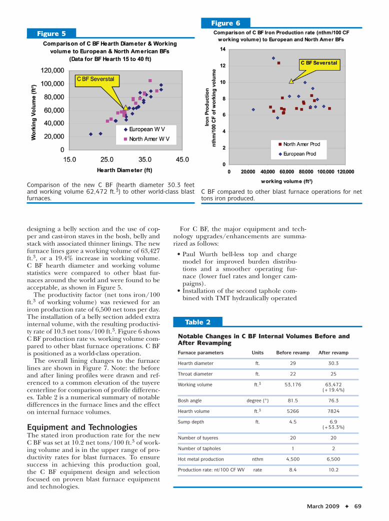
designing a belly section and the use of cop-per and cast-iron staves in the bosh, belly and stack with associated thinner linings. The new furnace lines gave a working volume of 63,427 ft.3, or a 19.4% increase in working volume. C BF hearth diameter and working volume statistics were compared to other blast fur-naces around the world and were found to be acceptable, as shown in Figure 5.
The productivity factor (net tons iron/100 ft.3 of working volume) was reviewed for an iron production rate of 6,500 net tons per day. The installation of a belly section added extra internal volume, with the resulting productivi-ty rate of 10.3 net tons/100 ft.3. Figure 6 shows C BF production rate vs. working volume com-pared to other blast furnace operations. C BF is positioned as a world-class operation.
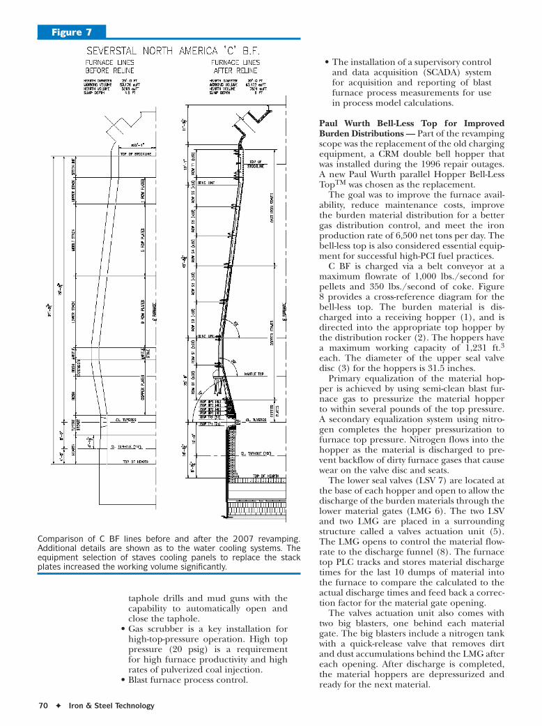
The overall lining changes to the furnace lines are shown in Figure 7. Note: the before and after lining profiles were drawn and ref-erenced to a common elevation of the tuyere centerline for comparison of profile differenc-es. Table 2 is a numerical summary of notable differences in the furnace lines and the effect on internal furnace volumes.
Equipment and Technologies The stated iron production rate for the new C BF was set at 10.2 net tons/100 ft.3 of work-ing volume and is in the upper range of pro-ductivity rates for blast furnaces. To ensure success in achieving this production goal, the C BF equipment design and selection focused on proven blast furnace equipment and technologies.
For C BF, the major equipment and tech-nology upgrades/enhancements are summa-rized as follows:
• Paul Wurth bell-less top and charge model for improved burden distribu-tions and a smoother operating fur-nace (lower fuel rates and longer cam-paigns).
• Installation of the second taphole com-bined with TMT hydraulically operated
Figure 6
C BF compared to other blast furnace operations for net tons iron produced.
Figure 5
Comparison of the new C BF (hearth diameter 30.3 feet and working volume 62,472 ft.3) to other world-class blast furnaces.
Notable Changes in C BF Internal Volumes Before and After Revamping
Furnace parameters Units Before revamp After revamp
Hearth diameter ft. 29 30.3
Throat diameter ft. 22 25
Working volume ft.3 53,176 63,472 (+19.4%)
Bosh angle degree (°) 81.5 76.3
Hearth volume ft.3 5266 7824
Sump depth ft. 4.5 6.9 (+53.3%)
Number of tuyeres 20 20
Number of tapholes 1 2
Hot metal production nthm 4,500 6,500
Production rate: nt/100 CF WV rate 8.4 10.2
Table 2
70 ✦ Iron & Steel Technology
taphole drills and mud guns with the capability to automatically open and close the taphole.
• Gas scrubber is a key installation for high-top-pressure operation. High top pressure (20 psig) is a requirement for high furnace productivity and high rates of pulverized coal injection.
• Blast furnace process control.
• The installation of a supervisory control and data acquisition (SCADA) system for acquisition and reporting of blast furnace process measurements for use in process model calculations.
Paul Wurth Bell-Less Top for Improved Burden Distributions — Part of the revamping scope was the replacement of the old charging equipment, a CRM double bell hopper that was installed during the 1996 repair outages. A new Paul Wurth parallel Hopper Bell-Less TopTM was chosen as the replacement.
The goal was to improve the furnace avail-ability, reduce maintenance costs, improve the burden material distribution for a better gas distribution control, and meet the iron production rate of 6,500 net tons per day. The bell-less top is also considered essential equip-ment for successful high-PCI fuel practices.
C BF is charged via a belt conveyor at a maximum flowrate of 1,000 lbs./second for pellets and 350 lbs./second of coke. Figure 8 provides a cross-reference diagram for the bell-less top. The burden material is dis-charged into a receiving hopper (1), and is directed into the appropriate top hopper by the distribution rocker (2). The hoppers have a maximum working capacity of 1,231 ft.3 each. The diameter of the upper seal valve disc (3) for the hoppers is 31.5 inches.
Primary equalization of the material hop-per is achieved by using semi-clean blast fur-nace gas to pressurize the material hopper to within several pounds of the top pressure. A secondary equalization system using nitro-gen completes the hopper pressurization to furnace top pressure. Nitrogen flows into the hopper as the material is discharged to pre-vent backflow of dirty furnace gases that cause wear on the valve disc and seats.
The lower seal valves (LSV 7) are located at the base of each hopper and open to allow the discharge of the burden materials through the lower material gates (LMG 6). The two LSV and two LMG are placed in a surrounding structure called a valves actuation unit (5). The LMG opens to control the material flow-rate to the discharge funnel (8). The furnace top PLC tracks and stores material discharge times for the last 10 dumps of material into the furnace to compare the calculated to the actual discharge times and feed back a correc-tion factor for the material gate opening.
The valves actuation unit also comes with two big blasters, one behind each material gate. The big blasters include a nitrogen tank with a quick-release valve that removes dirt and dust accumulations behind the LMG after each opening. After discharge is completed, the material hoppers are depressurized and ready for the next material.
Figure 7
Comparison of C BF lines before and after the 2007 revamping. Additional details are shown as to the water cooling systems. The equipment selection of staves cooling panels to replace the stack plates increased the working volume significantly.

March 2009 ✦ 71
The empty signal for completed material dump from a top hopper is determined using the load cells installed on each top hopper to monitor the weight. Sonic detectors, located below the LSV, provide a secondary means to detect an empty hopper by monitoring the sound (noise) that the burden material makes as it flows on the internal metal surface.
The burden materials are charged and layered at the furnace top using a chute that rotates 360° and drops vertically, allowing almost infinite possibilities for the placement materials. The water-cooled transmission gear-box (12) sits on the top flange. The gearbox has a planetary gear drive (9) that enables the simultaneous rotation and tilting (13) of the 3.5-m distribution chute (15).
Charge Model for Bell-Less Top — Because of the nearly unlimited possibilities to distribute burden materials with the distribution chute, a tool was developed to help the blast furnace operator determine potential burden distri-butions prior to implementing the charge sequence on the furnace. This aid came in the form of a mathematical calculation or charge model that would predict the shape, profile and location of the burden materials. This visual aid is a quick and easy way to compare burden distributions for problems and issues with material placement.
The prime inputs into the calculations are the charge sequence, weights of materials and ring settings. Measurement of the material falling curves (which were made during the initial furnace fill) is required for the model calculation. The material trajectories are used to determine the burden profile, layering and ore/coke ratios across the burden. Figure 9 is an example of the charge model–calculated burden distribution and profile output.
Installation of the Second Taphole — To further improve the stability and promote good casting practices, a second taphole was installed, offset 90° from the north taphole. A new east casthouse was constructed, complete with a 25-ton overhead crane.
A common casting control room was locat-ed between the two casthouses, so that viewing windows allowed a clear line of sight for safe operation of the taphole drills and mud guns. Modern, TMT hydraulically operated taphole drills and mud guns were installed on both tapholes. To conserve casthouse floor space, the drills and guns were located on the same side of the taphole.
Figure 10 depicts the taphole drill, and Figure 11 shows the mud gun installation on C BF. Remote, radio control operation of the drills and guns allows for direct observations on the opening and closing of the taphole.
Within four months of start-up, the taphole was being closed almost 100% in automatic mode and opening the taphole about 75% of the time in automatic mode, with progress being made with the casting crews.
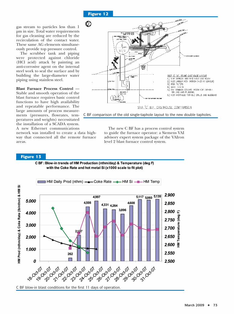
The new casthouse layout is detailed in Figure 12. The outline of the old single
Figure 8
Cross-reference diagram for the PW bell-less top description.

72 ✦ Iron & Steel Technology
taphole arrangement is compared to the new double-taphole setup. The new iron trough is 21 feet longer than the prior trough. Iron and slag titling runners replaced the fixed-position casting.
Gas Scrubber — A new annular gap scrub-ber (AG scrubber) was installed on C BF for simultaneous gas cleaning and top pressure control. Three hydraulically operated cone ele-ments provide dedusting of the blast furnace
Figure 9
Example of the charge model–calculated burden distribution and profile.
Figure 10
TMT hydraulically operated taphole drill.
Figure 11
TMT hydraulically operated mud gun.
March 2009 ✦ 73
gas stream to particles less than 1 μm in size. Total water requirements for gas cleaning are reduced by the recirculation of the contact water. These same AG elements simultane-ously provide top pressure control.
The scrubber tank and piping were protected against chloride (HCl acid) attack by painting an anti-corrosive agent on the internal steel work to seal the surface and by building the large-diameter water piping using stainless steel.
Blast Furnace Process Control — Stable and smooth operation of the blast furnace requires basic control functions to have high availability and repeatable performance. The large amounts of process measure-ments (pressures, flowrates, tem-peratures and weights) necessitated the installation of a SCADA system. A new Ethernet communications network was installed to create a data high-way that connected all the remote furnace areas.
The new C BF has a process control system to guide the furnace operator: a Siemens VAI advisory expert system package of the VAIron level 2 blast furnace control system.
Figure 12
C BF comparison of the old single-taphole layout to the new double tapholes.
Figure 13
C BF blow-in blast conditions for the first 11 days of operation.

74 ✦ Iron & Steel Technology
The advisory expert system has the follow-ing process models:
• Burden control model. • Shaft simulation model. • Indirect reduction model. • Raceway calculation model. • Flame temperature model. • Tapping management model. • Blast simulation model.
The new blast furnace office building con-tains the new furnace control room with operator stations (HMI) and wall-mounted display screens.
Blow-In The furnace was blown in Oct. 18, 2007, when wind was put on at 5 p.m. at 80,000 scfm. The furnace was restarted using the north taphole, keeping the east one in reserve. The first iron was cast to slag pots until hot metal tempera-ture and volumes increased sufficiently for the iron to be used at the BOF steel shop. No. 14 tuyere was lost on start-up with a burnt nose compartment.
Figure 13 illustrates trends of the blast con-ditions, and Figure 14 shows the trend of the hot metal production and temperature dur-ing the blow-in.
Blowers and Pulverized Coal Injection FacilitiesThe following facilities are being installed after the blow-in of the furnace due to delivery schedules of the equipment.
Previously, C BF wind was generated by two steam blowers. To operate at higher top pres-
sures and at higher wind rates, two new axial blowers are being installed. The axial blowers are rated at 25,183 hp and are designed to run at speeds between 4,080 and 5,355 rpm, producing up to 163,000 scfm at a maximum operating pressure of 88 psig. The new blow-ers are being installed in a new separate build-ing and will be tied into the existing cold blast main with a new snort valve.
An integral component of the rebuilt C BF was the adoption of pulverized coal injec-tion technology (Daneili Corus). Primary components in the PCI system include: pulverized coal bin, three feed tanks, coal distributor, tuyere Blocktector system and tuyere lances. The PCI system is designed to run at a maximum rate of 440 lbs./nthm. The pulverized coal bin has a capacity of 950 tons, and will allow for 16 hours of coal delivery at full production. Coal is gravity-fed from the coal bin into one of three feed tanks. Nitrogen is used to transport the coal into the proprietarily designed coal distribu-tor. The coal flowrate is controlled by nitro-gen pressure using a load cell system that controls to a target setpoint, using a lbs./nthm injection rate basis. The distributor is designed such that equal delivery rates are achieved at each tuyere. A Blocktector sys-tem will be installed to monitor and alarm a blocked tuyere event.
ConclusionThe 2007 revamping of C BF was completed ahead of schedule and installed modern, state-of-the-art blast furnace equipment and tech-nologies. Equipment design and selection has
Figure 14
C BF trend of hot metal production and temperature with blow-in coke rate with HM Si (x1,000).

March 2009 ✦ 75
transformed Severstal NA C BF into a world-class operation.
Innovative construction and erection meth-ods reduced the furnace outage by approxi-mately 15–20 days. The revamping was com-pleted with a safety record that had fewer lost-time accidents and first aid incidents compared to industry standards.
The equipment and technologies have posi-tioned C BF with the tools to achieve 6,500 net tons of iron per day. Current operating performance has demonstrated a production output at this rate. ✦
Did you find this article to be of significant relevance to the advancement of steel technology? If so, please consider nominating it for the AIST Hunt-Kelly Outstanding Paper Award at www.aist.org/huntkelly.
This paper was presented at AISTech 2008 — The Iron & Steel Technology Conference and Exposition, Pittsburgh, Pa., and published in the Conference Proceedings.
U.S. Blast Furnace Production Reaches 20-Year LowThe worldwide economic crisis has led U.S. steel producers to cut back on their production in a
measure not seen in decades. The following data shows U.S. and Canadian blast furnace capacity versus levels of production as of December 2008.
Total capacity No. of BFs CurrentUSA mill Total BFs (tons) currently running tonnageArcelor Mittal 9 48,600 3 15,300U. S. Steel 12 48,800 4 15,500Severstal 5 25,500 1 3,800AK Steel 2 11,500 1 6,300Republic 1 3,500 0 0Total USA 29 137,900 9 40,900
Total capacity No. of BFs CurrentCanadian mill Total BFs (tons) currently running tonnageArcelor Mittal 3 10,403 2 5,602U. S. Steel 2 12,300 1 4,400Essar 2 10,500 1 4,500Total Canada 7 33,203 4 14,502
Source: American Iron and Steel Institute.
DiD You Know?