SEVENTH BIENNIAL SYMPOSIUM - … · counterweight consists of a steel box shaped to match the ......
27
Heavy Movable Structures, Inc. SEVENTH BIENNIAL SYMPOSIUM November 4 - 6,1998 Grosvenor Resort Walt Disney World Village Lake Buena Vista, Florida "A Structurally Efficient and Aesthetic Bascule Leaf Design for the 17th Street Causeway Bridge" George C. Patton, EC Driver and Associates
Transcript of SEVENTH BIENNIAL SYMPOSIUM - … · counterweight consists of a steel box shaped to match the ......

Heavy Movable Structures, Inc.
SEVENTH BIENNIAL SYMPOSIUM November 4 - 6,1998
Grosvenor Resort Walt Disney World Village Lake Buena Vista, Florida
"A Structurally Efficient and Aesthetic Bascule Leaf Design for the 17th Street
Causeway Bridge"
George C. Patton, EC Driver and Associates

A Structurally Efficient and AestJzetic Bascule Leaf Design for the 17th Street Causeway Bridge
George C. Patton, P.E. E. C. Driver & Associates, Inc.
Tampa, Florida
INTRODUCTION
The 17th Street Causeway is viewed as the "Gateway to Ft. Lauderdale" - a site deserving of Florida's newest signature bridge. The bridge is the first encountered by navigation traffic entering the Atlantic Intracoastal Waterway at Port Everglades south of Ft. Lauderdale. Ft. Lauderdale is appropriately deemed the "Yachting Capital of North America" with its numerous high mast sail boats and stately yachts that frequent the area. The bridge further serves as an important link canying AlA to the famed Ft. Lauderdale Beaches and a focal point to the area with the adjacent Port Everglades Cruise Ship Terminal, Pier 66, the Ft. Lauderdale Convention Center, and numerous vacation hotels.
As the existing drawbridge approached its useful service life, the residents of Ft. Lauderdale demanded a replacement bridge that greatly reduced the traffic problems caused by the frequent bridge openings and equipment failures. Furthermore, the new facility was to make a grand statement, characteristic of the site. Following a lengthy and thorough project development study, tunnel and high-level fixed bridge alternatives were determined to be cost prohibitive or impractical with too many adverse impacts on the public and area businesses. In the end, a high-level drawbridge was determined to be the most feasible solution for the site.
The local community was provided the opportunity to participate in the selection of the appearance of the new bridge through a charette process. The community specified their desire for a bridge with a high-level of aesthetics, however, the visual appeal was to be achieved through graceful arc 'tectural form and not through the addition of external themeing. Furthermore, the cost % conscientious community specified that the cost of the new bridge not suffer in achieving the aesthetic design. This direction and some creative thinking lead to the development of a unique contemporary signature bascule bridge that also exhibits remarkable structural efficiency and practicality. (See Figure 1.)
At first glance, the unique V-shaped bascule piers (termed "Carina Piers") are an obvious point of interest. However,'there are also numerous aspects of the movable span superstructure of equal interest including many features not commonly used in movable bridges that were implemented in this project to achieve an aesthetic and structurally efficient bascule leaf design.
A Structurally Efficient and Aesthetic Bascule Leaf Design for the 17" Street Causeway Bridge
P Biennial Movable Bridge Symposium

FIGURE 2. ARTISTS RENDERING - 17?" STREET CAUSEWAY REPLACEMENT BRIDGE
CONFIGURATION
The movable span consists of twin double-leaf trunnion bascule spans with a len,oth of 64.0 m (2 1 0') center to center of trunnions (54.0 m [I 77'-2"] center to center of load shoes.) Each leaf has an overall length of 44.0 m (244'-4") from tip to tail. The bridge spans a 38.2 m (135') wide navigation channel skewed to the centerline of the bridge 12 "3 1'55" and provides 16.764 m (55') of vertical clearance at the face of fenders with the span closed and unlimited vertical clearance with the span raised to its maximum operating angle of 75 ". (See Figure 2 & 3.)
Each of the twin spans carries two 3.6 m (12') lanes, a 3.0 m (lOf)outside shoulder and 2.4 m (8') inside shoulder and a 2.4 m (8') sidewalk. The 16.295 m (53'-5%") wide spans are separated by a 4.0 m (1 3'-1%") open median. The bridge width can temporarily accommodate four 3.0 m (1 0') lanes and a 1.7 m (5'-7") sidewalk on one of the twin spans to pennit phased construction. The bascule span has a closed deck with a 2% cross slope for drainage.
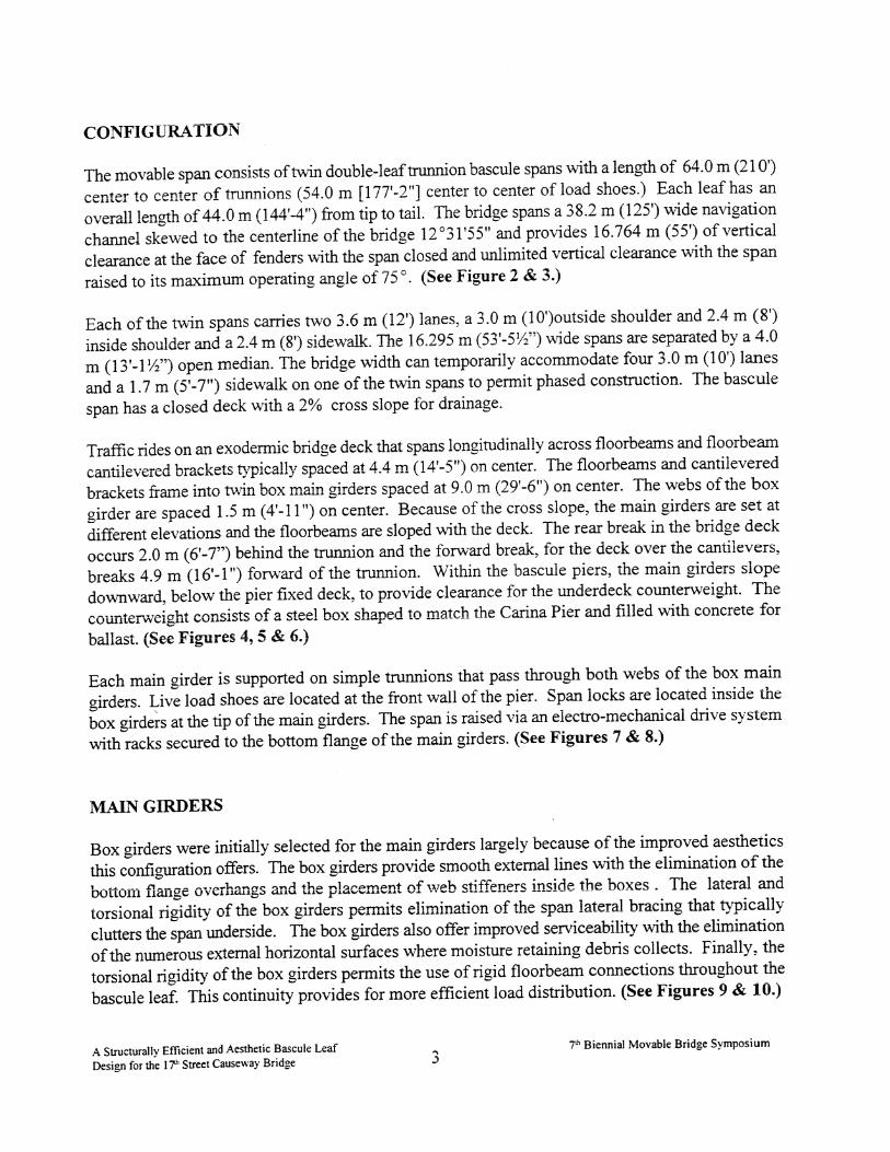
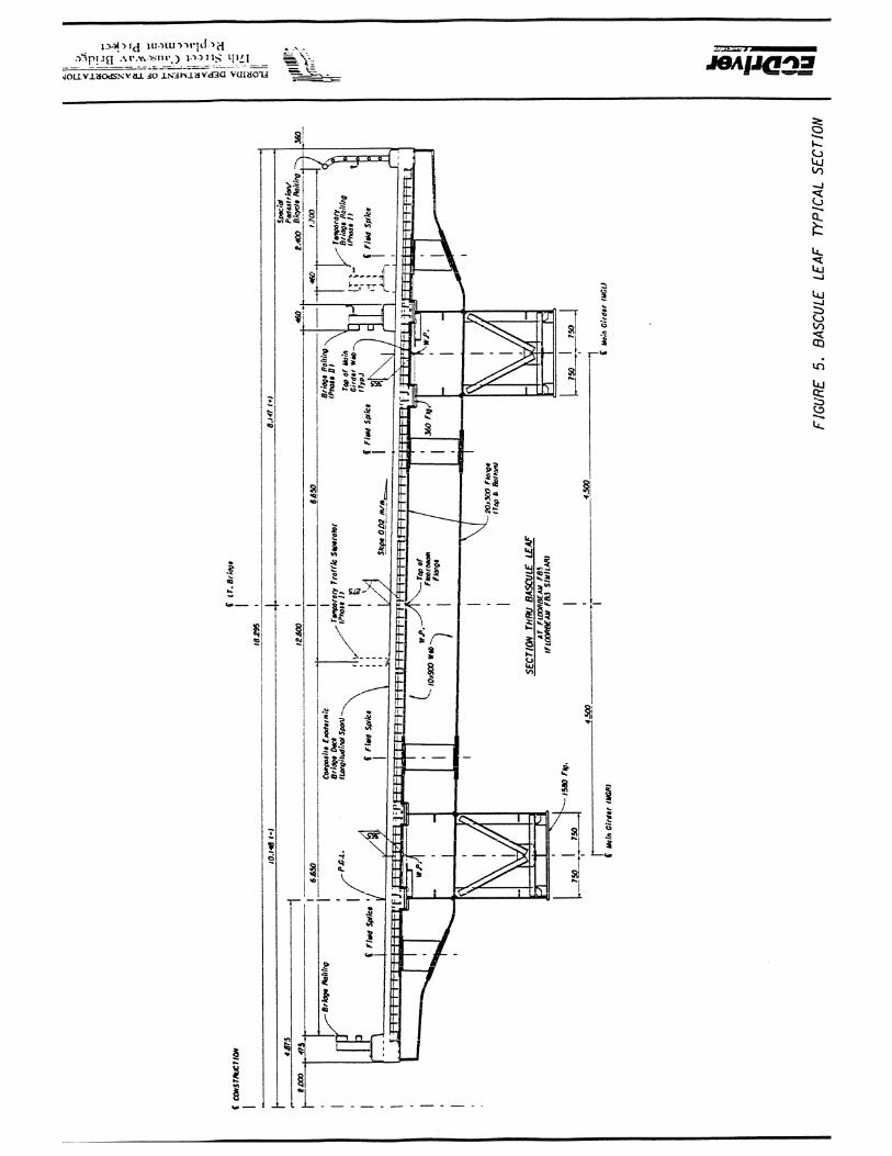
Traffic rides on an exodermic bridge deck that spans longitudinally across floorbeams and floorbeam cantilevered brackets typically spaced at 4.4 m (14'-5") on center. The floorbeams and cantilevered brackets frame into twin box main girders spaced at 9.0 m (29'-6") on center. The webs of the box girder are spaced 1.5 m (4'-11") on center. Because of the cross slope. the main girders are set at different elevations and the floorbeams are sloped with the deck. The rear break in the bridge deck occurs 2.0 m (6'-7") behind the trunnion and the forward break, for the deck over the cantilevers, breaks 4.9 m (16'-1") forward of the trunnion. Within the bascule piers, the main girders slope downward, below the pier fixed deck, to provide clearance for the underdeck counterweight. The counterweight consists of a steel box shaped to match the Carina Pier and filled with concrete for ballast. (See Figures 4,5 & 6.)
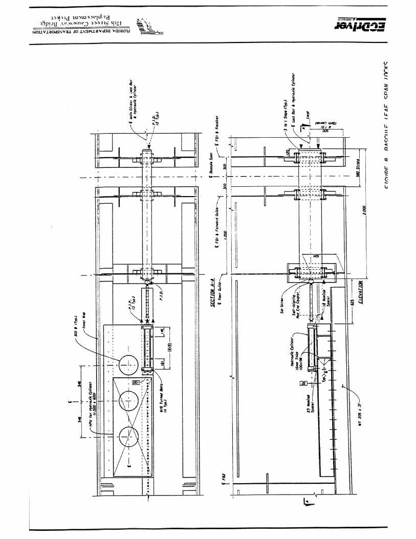
Each main girder is supported on simple trunnions that pass through both webs of the box main girders. Live load shoes are located at the front wall of the pier. Span locks are located inside the box at the tip of the main girders. The span is raised via an electro-mechanical drive system with racks secured to the bottom flange of the main girders. (See Figures 7 & 8.)
MAIN GIRDERS
Box girders were initially selected for the main girders largely because of the improved aesthetics this configuration offers. The box girders provide smooth external lines with the elimination of the bottom flange overhangs and the placement of web stiffeners inside the boxes . The lateral and torsional rigidity of the box girders permits elimination of the span lateral bracing that typically clutters the span underside. The box girders also offer improved serviceability with the elimination of the numerous external horizontal surfaces where moisture retaining debris collects. Finally, the torsional rigidity of the box girders permits the use of rigid floorbeam connections throughout the bascule leaf. This continuity provides for more efficient load distribution. (See Figures 9 & 10.)
A Structurally Efficient and Aesthetic Bascule Leaf Design for the 17' Street Causeway Bridge
7& Biennial Movable Bridge Symposium 3


Forward of the bascule pier, the main girders consist of open-tub box girders. The open-tub configuration is of more conventional construction and is generally considered easier to fabricate than a closed box. As is typical of open-tub box girders, the deck, which is composite with the main girders, completes the box section. Diagonal bracing between the top flanges and internal K- diaphragms spaced at 8.8 m (28'-10%") helps maintain the geometry of the boxes during handling, erection and deck construction. Within the bascule pier, the open-tub box girders transition to a closed-box configuration. The closed-box provides a torsionaIly rigid element in the region of the trunnions where it is imperative to maintain alignment of the main girders. As the main girders slope downward to provide clearance below the deck for the countenveight, it is no longer practical for the deck to be made composite with the main girders as the haunches over the girders would have to be excessive. A smooth transition is used to eliminate stress risers and expensive details associated with sharp transitions.
Weight savings in the bascule leaf structural steel translates to savings throughout the structure including the counterweight, bridge operating machinery, pier concrete and reinforcing, etc. In order to minimize the weight of the bascule leaf while maintaining adequate stiffness for alignment and serviceability, a combination of transverse and longitudinal web stiffeners are used to minimize the box girder web thickness. Because of the twin webs and depth of box required for maintenance access, shear is not a controlling element in the sizing of the web plates, thus minimum thickness web plates can be used. With the addition of longitudinal web stiffeners, this minimum web thickness is further reduced . This significant savings in weight more than offsets the additional labor cost of the stiffeners. As the configuration of a double-leaf bascule bridge introduces both negative and positive moments within the main girders, longitudinal stiffeners are provided near both the top and bottom flanges of the girder. As longitudinal stiffeners are required on one side of the web only, they can be placed within the box girders, thus not detracting from the appearance of the bridge or creating external horizontal surfaces where moisture retaining debris might collect. A continuous longitudinal stiffener centered on the bottom flange permits the thickness of the bottom flange to similarly be reduced.
Fatigue is typically a concern viith longitudinal stiffeners, as the weld termination at the end of the longitudinal stiffener is classified as a Category E fatigue detail. However, in this case, fatigue at these locations did not control the design of the girder. As the main girder cantilevered dead load stresses are large relative to the live load stresses, the largest stress range is due to the dead load. There is a significant change in girder bending stresses as the span operates through its full opening and closing cycle. However, as only 100,000 cycles need to be considered for this load case, a higher allowable fatigue stress range is considered. In addition, the live load tensile stresses in the bottom of the girder are typically lower than the dead load stresses resulting in net compression and thus no calculated live load stress range exists in the bottom of the girder. Conversely, the girders exhibit a larger live load stress range in the top of the girder. However, the composite section raises the neutral axis closer to the longitudinal stiffeners, thus resulting in a low fatigue stress range. Furthermore, the low percentage of trucks on this facility (i.e., ADTT less than 2500) requires that only 100,000 cycles of lane load be considered and 500,000 cycles of truck load be considered. For
A Structurally Efficient and Aeslhetic Bascule Leaf Design for the 1 7 Street Causeway Bridge 13
7" Biennial Movable Bridge Symposium

this longer span, lane loads govern over truck loads for much of the girder ]en,&. As the provisions of the AASHTO code allows for a higher allowable fatigue stress range for lane loads than truck loads, the main girders are not penalized for the higher lane load fatigue stresses. As the fatigue did not control the design, a less expensive Iongitudinal stiffener detail could be used and the overall weight of the girders significantly reduced.
A field splice is provided to allow the main girders to be broken down into manageable components for shipping and handling during erection. The splice is located to permit the rear half of the leaf to be erected in the closed position without interference with the existing bridge operation.
Because of the unique configuration of the box girders, there are several load transfer issues that had to be addressed. The rack support frame is attached to longitudinal stiffeners welded to the bottom flange of the box girder. Similar longitudinal stiffeners in line with the rack support frame connection stiffeners are welded on the inside of the box. The torque from the rack is transferred through the longitudinal stiffeners to a pair of transverse diaphragms located near the ends of the rack and directly connected to the internal longitudinal stiffeners. The diaphragms resist the torque as a force couple and transfer the loads to the main girder webs. As such, no concentrated loads are applied directly to the main girder bottom flange and the concern of transverse bending in the box girder flange is eliminated. Fatigue at the ends of the welded longitudinal stiffeners is reduced with properly detailed end radii on the stiffeners. (See Figure 11.)
The large concentrated reaction at the live load shoe, centered on the box girder bottom flanee, is similarly transferred to the main girder webs through a transverse diaphragm located directly above the load shoe.
Location of the span locks within the box girders provides an opportune configuration to eliminate eccentric mounting of the span locks and corresponding eccentric loading on the main girders. Eccentric mounting of span locks is typical and problematic of single web main girders. This location also eliminates the need for unsightly maintenance access platforms. Diaphragms located at the end of the box girder house the span lock forward guide and receiver. A bolted cover plate on the end diaphragm provides for easy removal of the span lock equipment through an opening in the end of the box girder. An additional diaphragm located just behind the front diaphragm houses the span lock rear guide.
A new technology, energy absorbing thermoplastic alloy is used for the bumper blocks. The bumper blocks are mounted on the lower part of the bascule pier front diaphragm in line with the main girders. A transverse internal diaphragm is located inside the box to transfer the concentrated reaction to the webs of the box girders.
As previously mentioned, the box girder depth is sized for maintenance access. The depth is a minimum of 2.000 m (6'-7") at the tip of the leaves and a maximum of 3.061 m (10'-0%") within the bascule pier. Entrance to the box is gained by way of an access opening and hatch provided in the
A Structurally Efficient and Aesthetic Bascule Leaf D e s i ~ n for the 17" Street Causeway Bridge 14
7"' Biennial Movable Bridge Symposium


web of the girder at the bascule pier. An intercom system within the box permits maintenance personnel to communicate with the bridge operator. Ventilation and lighting is provided within the box and the interior is painted white to facilitate inspection.
FLOORBEAMS
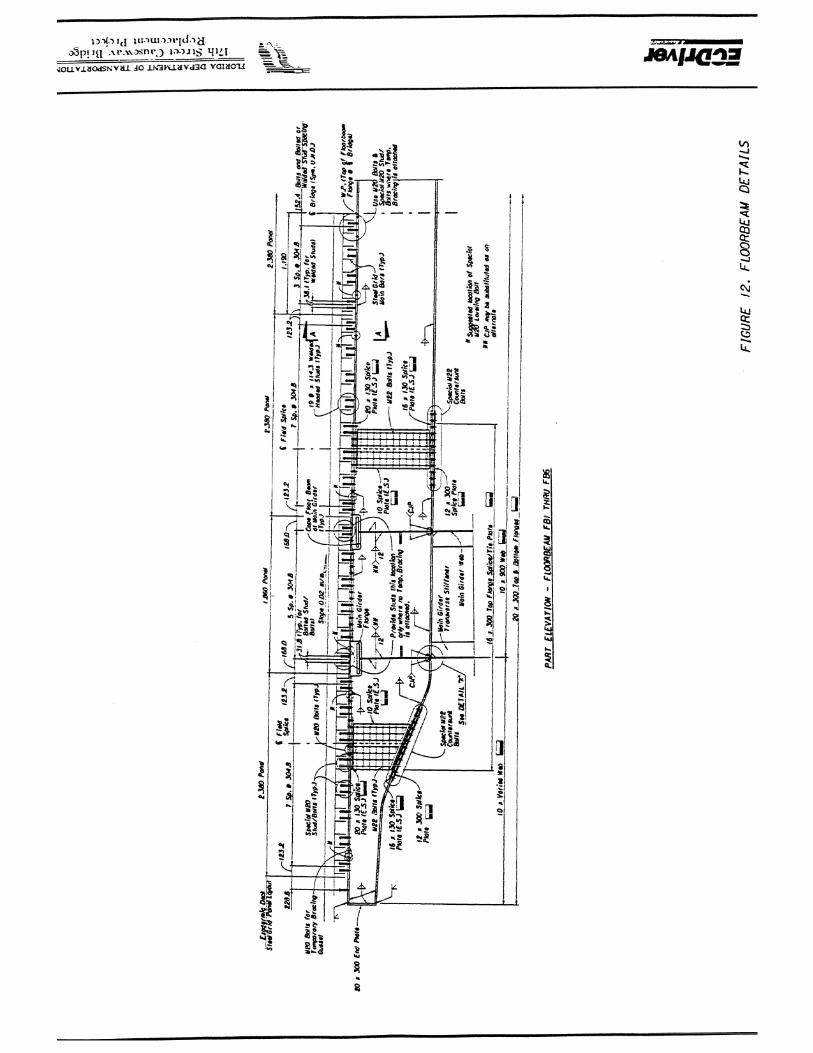
The floorbeams are welded directly to the webs of the main girders to provide structural efficiency through continuity. These welded connections also provide clean external details with the elimination of visible external transverse connection stiffeners on the main girders that would have broken the smooth, continuous fascia lines. Field splices are provided at the inflection points of the floorbeams between the main girders where flexural stresses are a minimum. Similarly, field splices are provided in the cantilever floorbeam brackets at a location where stresses are low. As with the main girder, the field splices are provided to permit the leaf to be broken down into manageable components. (See Figure 12.)
Integral internal diaphragms within the main girder boxes, located at each floorbeam, maintain continuity of the floorbeams. The main girders resist the floorbem bending loads in torsion and the floorbeam reactions in shear. The internal diaphragms, together with transverse web stiffeners and K-bracing assist in the transfer of these forces. The top splice plate for the floorbearn field splices also serve as a tie plate to the main girder internal diaphragms.
The back-to-back floorbeam and internal diaphragm bottom flanges are welded to the web of the main girders with complete joint penetration welds. The fatigue stresses at these connections were checked in two different directions. These short length welds are oriented in the direction of applied stress in the main girder and thus introduce a Category E fatigue detail. The composite deck raises the neutral axis close to these welds yielding a relatively low stress range. The stress range o f the connection, in the direction of floorbeam applied stress, is low as the floorbeam bottom flange is primarily in compression because of negative bending moments.
The first six (6) floorbeams forward of the bascule pier (FBI - FB6) are nearly identical in configuration creating cost savings through repetition. Floorbeam FB7, located just inside the bascule pier, uses the similar welded framed connections for continuity, however, the girder is deeper to stiffen the trunnion region of the leaf. Floorbeam FB8 is a deep floorbeam and frames into the transverse web of the main girders. Continuity is provided with the main girder through a deep bolted connection and a top flange tie plate. Floorbeam FB9 is a short depth simple framed member sized to provide clearance of the inboard trunnion support pedestals.
EXODERMIC BRIDGE DECK
A concrete deck system is required on the bascule leaf to provide improved rideability and skid resistance characteristics and to reduce traffic induced noise. An exodemic deck system was selected because of the reduced weight and structural efficiency this design presents.
A Stn~cturally Efficient and Aesthetic Bascule Leaf Design for the 1 Th Street Causeway Bridge 16
7" Biennial Movable Bridge Symposium

The exodermic deck system consists of a 114 mm (4%") thick reinforced structural sandlightweight concrete slab made composite with a 132 mm ( 5 V ) manufactured steel grid. (See Figure 13.) The lightweight concrete specified has a unit weight of 1842 kg/m5 (1 15 pcf) utilizing expanded shale lightweight aggregate. Sand is used for the fine aggregate to provide improved wear and skid resistance. Composite action between the concrete slab and the steel grid is achieved through tertiary bars and a grid of studs that extend into the slab. The exodermic deck is made composite with the floorbeams and main girders to provide additional structural efficiency. Although this bridge is not the first bascule bridge to utilize an exodermic deck, this is the first bascule bridge to make the exodermic deck composite with the main longitudinal load carrying members.
The exodermic deck system was compared with a conventional reinforced concrete deck slab and a full depth grid reinforced concrete deck system with an overpour, both also utilizing structural lightweight concrete. Of the three systems, the exodermic deck proved to have the best combination of strength, weight and cost when considering the impact on the overall structure. The exodermic deck system has better negative moment section properties than a conventional reinforced concrete deck slab. With the exodermic deck, the steel grid bars and reinforcing can be considered in the calculation of the negative moment section properties, where as, in a conventional deck slab, only the reinforcement can be considered. This additional composite steel area reduces the steel required for the bascule leaf main girders. In a grid reinforced concrete deck, the concrete fills the spaces between the steel grid bars, where as, in the exodermic deck, the slab is mounted on top of the steel grid thereby maximizing the decks own composite section properties. As such, the exodermic deck is more efficient allowing it to span greater distances with less weight. In all three of these deck systems, the concrete contributes to the stiffness of the section, reducing deflections and therefore reducing vibrations.
The exodermic deck spans longitudinally 4.400 m (14'-5") from floorbeam to floorbeam permitting elimination of the steel stringers that typically support the deck between floorbeams. This provided a much more uncluttered design and eliminated a number of details (e-g., stringer end connections) typically susceptible to corrosion and fatigue.
The exodermic deck is made composite with both the floorbearns and main girders using a combination of bolted and welded stud shear connectors attached to the top flanges. The steel grid does not bear directly on the main girders and floorbeams eliminating the typical steel grid attachment concerns (e.g., non-uniform bearing of the warped panels on the steel, field welding of the steel grid panels, corrosion details, etc.) Leveling screws are provided to align the panels and temporarily support the steel grid until the concrete is placed and cured. Concrete haunches over the floorbeam and main girder top flanges make up any discontinuities due to the warping.
With the limited available room for floorbeam connection bolts and stud shear connectors, special bolted studs that double as both the splice connection bolts and stud shear connectors are used. The bolted studs are also used in other select areas on the floorbeams to reduce the fatigue category.
A Structurally Efficient and Aesthetic Bascule Leaf Design for the 17 Street Causeway Bridge 18
7'" Biennial Movable Bridge Symposium


Welded stud shear connectors are used everywhere else for economy. Because of the fixed locations of the floorbeam field splice bolted studs, careful layout of the grid deck main bars is necessary to provide erection clearances.
In general, the exodermic deck system significantly adds to the structural efficiency of the leaf by taking advantage of the composite section properties. As with conventional reinforced concrete deck slabs made composite with the girders, the concrete and reinforcing steel contributes to the positive moment section properties of the girder while only the reinforcing steel contributes to the negative moment section properties. With the exodermic deck, the steel grid can also contribute to the composite section properties: if made continuous via splicing of grid deck main bars and tertiary bars at the panel junctures. The transverse bars are not similarly spliced, as these bars are much smaller and do not provide the same significant advantage. Furthermore, the additional splicing complicates field erection of the panels. Transverse reinforcement is included in the section properties, however.
At the bascule pier, where the main girders slope below the deck, a composite termination o f the exodermic deck is required. At this location, the main girders transition from a composite open-tub box to a non-composite closed box. The in-plane membrane forces in the deck have to be transferred to the main girders at this point. This is accomplished via a field of shear studs attached to the main girder top flange.
Reinforced concrete edge beams are provided along the fascia of the leaf to account for the edge effects.
DESIGN AND ANALYSIS - FRAMING SYSTEM
In order to take advantage of the inherent efficiencies in the structural system, a thorough and systematic approach was required in the design. Several three-dimensional frame models were developed for the purpose of accounting for the lateral load distribution characteristics of the leaf. GT-STRUDL Software was used for this analysis. A single-leaf model using non-composite section properties was used to compute dead load forces. A second single-leaf model, using partial composite section properties (i.e., use of 3 x Modular Ratio, N), was used to compute superimposed dead load forces. These two models were also used to compute dead load deflections for developing camber profiles for the main girders. A third single-leaf model with full composite section properties was used to compute wind load forces and a double-leaf model with full composite section properties was used to compute live load forces. Negative moment composite section properties were conservatively used in the models for load distribution purposes. Positive moment section properties were used in computing live load deflection.
A series of unit loads were applied to the live load model for purposes of developing live load influence lines. Influence lines were developed for bending moment, shear, torsion and deflection for the main girders and floorbeams. Also developed were influence lines for main girder trunnion
A Structurally Eff~cienl and Aeslheric Bascule Leaf Design for the 1 P Street Causeway Bridge 20
7"' Biennial Movable Bridge Symposium

and load shoe reactions, shear at the span locks and load distribution to the main girders. Simple distribution, as is typically used, was found to be overly conservative for this design. Appropriate MS 18 lane and truck loads and alternate military loading was applied.
A spreadsheet was used to compute and superimpose stresses for the AASHTO load combinations and to summarize stresses for both stren,oth and fatigue. Appropriate section properties were applied for each load.
The efficient design is illustrated through review of the influence lines. The continuity between the floorbeams and main girders and the torsional resistance of the main girders provides more efficient load distribution. Factors for lateral load distribution were calculated using the influence values from the three-dimensional frame analysis for the reaction of the floorbeam loads on the main girder. These calculations yielded distribution factors ranging from 3.939 to 4.279. These values are lower than the 4.484 distribution factor value computed using simple distribution. (Note that the load distribution influence lines from the frame analysis varies along the length of the span because of the varying torsional and bending stifhess of the main girders.) Reduction in live load distribution to the main girders ranges from 5% to 12% as a result of the improved distribution. (See Figure 14.)
The continuity and torsional resistance provides additional structural efficiency by m-ay of redistribution of loads from one main girder to the opposite girder. Comparison of main girder bending moment influence values from the three-dimensional frame analysis with influence values from a simple two-dimensional analysis reveals significant reductions in forces. Reduction in live load bending moments ranges from 30% to 50% as a result of the redistribution. (The influence line for main girder bending at the live load shoe is presented for illustration.)
DESIGN AND ANALYSIS - EXODERMIC DECK SYSTEM
The exodermic deck functions in two different ways. The deck canies wheel loads to the floorbearns and the deck assists in resisting floorbeam and main girder flexural stresses through composite action.
Exodermic Bridge Deck, Inc.(EBDI) was most helpful in developing the deck system for the bascule span. They provided a preliminary design via an in-house developed analysis spreadsheet that includes computation of deck unit weight and deck composite section properties. With this information, the deck was evaluated for its span capabilities.
A similar spreadsheet was developed for purposes of computing composite section properties for the main girders and floorbearns. This information was used to compute the stresses in the deck, main girders and floorbeams. Tension in the deck concrete was limited to less than 3- to minimize the potential for cracking. Fatigue of the grid deck was also evaluated. The spliced connection of
A Structurally Efficient and Aesthetic Bascule Leaf Design for the I P Street Causeway Bridze 2 1
Th Biennial Movable Bridge Symposium


the grid deck, for purposes of maintaining main bar and tertiary bar continuity, was designed. Finally, a finite element plate analysis was performed for purposes of design of the deck edge beams.
LEAF BRACING
As the exodermic deck serves as a large diaphragm to resist lateral loads and the main girder boxes provide large torsional and lateral resistance, permanent lateral bracing for the leaf is not required. However, temporary bracing is provided until the deck is constructed to maintain alignment and to resist floorbearn weak axis bending due to the weight of grid deck panels placed with the bridge in the raised position. The temporary bracing consists of a combination of rods. clevises and turnbuckles secured with gusset plates to the floorbeams in the planes of the top and bottom flanges. The gusset plates can be unbolted after the deck is placed.
Permanent bracing is provided in the vicinity of the trunnions to assist in maintaining alignment of the main girders. The permanent bracing, located in the floorbeam bay immediately forward of the trunnions, consists of horizontal bracing in the plane of the floorbeam bottom flange and vertical bracing at the centerline of the bridge. The bracing was not provided in the trunnion bay to avoid possible conflicts with the trunnion supports.
COUNTERWEIGHT BOX
A steel counterweight box is provided to achieve an aesthetic shape to match the bascule pier without the complex forming for counterweight concrete exterior surfaces. The bottom soffit of the counterweight box is curved to match the bottom soffit of the bascule pier with the span in the closed position. The front face of the counterweight box is curved to tuck below the cantilevered machinery floor with the bridge in the open position. Curved internal diaphragms are used to achieve the aesthetic shape and to transfer loads to the transverse diaphragms which carry the weight to the main girders. (See Figure 15.)
The counterweight box and main girders are filled with heavy weight concrete with unit weights of 2,563 kg/m3 (160 pcf) and 5,335 kg/m3 (333 pcf). The steel box eliminates the concern of heavyweight aggregate, such as steel punchings or iron ore, from segregating and settling on the bottom of the concrete forms, introducing serviceability concerns.
"a Adjustment pockets with hatch covers are provided in the counterweight box and main girders. The pockets contain shelves provided at different elevations, above and below the trunnion, for vertical adjustment of the center of gravity. Pockets in the countenveight box, which are not accessible with the bridge closed are provided for coarse adjustment. Pockets in the main girders, which are accessible with the bridge closed, are provided for fine adjustment. Cast steel blocks are provided for the adjustment to minimize the pocket dimensions. A greater amount of counterweight adjustment, than that required by GSHTO, is provided to account for the greater anticipated variations in leaf weight because of the use of a concrete deck.
A Structurally Eff~cient and Aesthetic Bascule Leaf Design for the 1 Th Street Causeway Bridge 22
F Biennial Movable Bridge Symposium


JOINT ASSEMBLIES
There are several joint details developed to address special conditions inherent in the unique bascule span design. The closed deck collects and channels a great deal of storm water towards the bascule pier. As such, sealed joints are required in order to minimize the water that enters the pier. A conventional compression seal was used in a unique way to seal the rear joint. The compression seal is clamped into an armored assembly at the rear joint. The seal rotates with the bridge and compresses against the underside of the adjacent pier armored assembly.
The longitudinal joints are sealed using a folded reinforced neoprene membrane secured to an armored assembly attached to the bascule pier side of the joint. The neoprene compresses against the side of the adjacent bascule leaf armored assembly to seal the longitudinal joint with the bridge closed and slides against the armored edge assembly during bridge operation. A stainless steel gutter system is provided below the joint to collect water that falls through the joint when the bridge opens.
A finger joint assembly is provided at the tip of the bascule leaves to accommodate as much as h60 mm (*23/8") of longitudinal movement. This movement is greater than encountered in most bascule spans as a result of rotation at the base of the bascule pier caused by longitudinal wind loads, temperature, creep and shrinkage effects. As with the other joint assemblies, the finger joint assembly is integrated into the exoderrnic deck. A centering device is provided at the tip of the span to ensure the fingers are aligned as the leaves come together. Replaceable finger plates are provided in the event they become damaged.
BRIDGE RAILINGS & LIGHTING
The traffic railing selected for this bridge offers several unique aspects. The Illinois Standard Traffic Railing used is crash tested to AASHTO Performance Level 2. Rarely do traffic railings or bamers on the bascule leaf meet the crash testing requirements largely because most crash tested barriers are hea\iy and would provide undue burden on the balancing and operating requirements for the bascule leaf. This railing is relatively lightweight consisting of tubular rail elements and steel wide flange posts mounted on a lightweight concrete curb.
This railing was also selected based on the communities desire for an open railing that would less restrict views from the bridge. The components of the railing are easily maintainable as components are replaceable and readily accessible for cleaning and painting.
OPERATING MACHINERY
Because of the heavy vehicular and marine traffic at the site, the Department placed a great importance on maintaining bridge operation, even during periods of repairs and rehabilitation. Thus, criteria was imposed to eliminate as many of the single-point failure elements and to implement as much redundancy as practical.
A Structurally Efficient and Aesthetic Bascule Leaf Design for the 17" Street Causeway Bridge
7"' Biennial Movable Bridse Symposium

The unique structural configuration (i-e., main girder torsional rigidity and continuity in the bascule leaf framing) provides the opportunity for redundant trunnion bearings. The bridge rotates about a pair of trunnion assemblies. Each consists of a trunnion shaft that passes through both webs of the box girder and is secured to the webs via a hub assemblies. Instead of utilizing an interference fit for purposes of load transfer between the hubs and the webs, load transfer is accomplished solely through turned bolts in a bearing type connection. A loose fit between the hubs and webs eliminates the difficult task of performing a shrink fit of the trunnion shaft through two hubs at once. The outside diameter of the inboard hub is purposely sized smaller than the hole in the outboard web to permit installation of the trunnion assembly in single shrink fit operation. The trunnion shafts are supported on spherical roller bearings. The span can remain operational with either of the inboard bearings removed to permit repairs, reconditioning or replacement. In the event an outboard bearing requires work, an inboard bearing can be temporarily moved to the outboard location. The bridge can not remain in service with load on an inboard bearing only, as the additional reactions would overload the cantilevered machinery platform beneath the inboard trunnion column. The bearings are sized to accommodate the larger reactions introduced with the removal of one of the bearings. The torsional rigidity of the main girder boxes and the rigid fra e connections between the main girder, floorbeams and counterweight box is adequate to temporarily support the inboard end of the trunnion in a Hopkins or overhung trunnion arrangement. The spherical roller bearings contain sufficient rotational capacity to accommodate the structure deformation.
SUMMARY
The innovative concepts and ideas used in the development of the 17& Street Causeway Bridge, including the box main girders, exodermic bridge deck, and framed floorbeam connections, yielded an aesthetic bascule leaf design with remarkable structural efficiency. The design yielded a low unit weight of structural steel equal to 392 kg/m2 (80 psf) (computed using the total weight of structural steel, excluding the steel counterweight box, divided by the area of deck from from outside edge to outside edge of the structure and load shoe to load shoe.) The exodermic deck adds a unit weight of 366 kg/m2 (75 psf) for a total bascule leaf unit weight of 758 kg/m2 (155 psf). The total weight of each leaf is 10,400 kN (1,169 Tons). The counterweight including steel box and concrete ballast weighs 6,193 kN (696 Tons).
A Structurally Efficient and Aesrheric Bascule Leaf Design for b e 1 F Street Causeway Bridge
7' Biennial Movable Bridge Symposium