
SETUP TIME REDUCTION IN A CNC PRODUCTION FACILITY...
92
i SETUP TIME REDUCTION IN A CNC PRODUCTION FACILITY THROUGH REDESIGN OF JIGS AND FIXTURES LAM PEI XIAN A project report submitted in partial fulfilment of the requirements for the award of the degree of Bachelor of Engineering (Hons) Industrial Engineering Faculty of Engineering and Green Technology Universiti Tunku Abdul Rahman August 2016
Transcript of SETUP TIME REDUCTION IN A CNC PRODUCTION FACILITY...
i
SETUP TIME REDUCTION IN A CNC PRODUCTION FACILITY
THROUGH REDESIGN OF JIGS AND FIXTURES
LAM PEI XIAN
A project report submitted in partial fulfilment of the
requirements for the award of the degree of
Bachelor of Engineering (Hons) Industrial Engineering
Faculty of Engineering and Green Technology
Universiti Tunku Abdul Rahman
August 2016

ii
DECLARATION
I hereby declare that this project report is based on my original work except for
citations and quotations which have been duly acknowledged. I also declare that it
has not been previously and concurrently submitted for any other degree or award at
UTAR or other institutions.
Signature : _________________________
Name : _________________________
ID No. : _________________________
Date : _________________________
iii
APPROVAL FOR SUBMISSION
I certify that this project report entitled “SETUP TIME REDUCTION IN A CNC
PRODUCTION FACILITY THROUGH REDESIGN OF JIGS AND
FIXTURES” was prepared by LAM PEI XIAN has met the required standard for
submission in partial fulfilment of the requirements for the award of Bachelor of
Engineering (Hons) Industrial Engineering at Universiti Tunku Abdul Rahman.
Approved by,
Signature : _________________________
Supervisor : Dr. Joshua A/L Jaya Prakash
Date : _________________________

iv
The copyright of this report belongs to the author under the terms of the
copyright Act 1987 as qualified by Intellectual Property Policy of Universiti Tunku
Abdul Rahman. Due acknowledgement shall always be made of the use of any
material contained in, or derived from, this report.
© 2016, Lam Pei Xian. All right reserved.

v
ACKNOWLEDGEMENTS
I would like to thank everyone who had contributed to the successful completion of
this project. I would like to express my gratitude to my research supervisor, Dr.
Joshua A/L Jaya Prakash for his invaluable advice, guidance and his enormous
patience throughout the development of the research.
In addition, I would also like to express my gratitude to my loving parent and
friends who had helped and given me encouragement.

vi
SETUP TIME REDUCTION IN A CNC PRODUCTION FACILITY
THROUGH REDESIGN OF JIGS AND FIXTURES
ABSTRACT
Jigs and fixtures play an important role in manufacturing. Its function is to arrange
the material in a definite position, so the machine tool is able to cut the required path
on the workpiece. The case study of this research is conducted in Company “X”. One
high demand product is “Y” which is the focus of this research. This product is
consists of three machining steps, where the first step is the bottleneck. The existing
problem for first step of product “Y” is setup time too long. Four techniques of setup
time reduction were introduced in this research which are Kaizen, just-in-time (JIT),
single minute exchange of dies (SMED), and jig and fixture design. The differences
between each technique were explained to decide the best method for setup time
reduction. A high demand product was selected for setup improvement. The setup
procedures were studied carefully and analysed to identify underlying problems of
current setup. After the new jig fabrication, an improved analysis was conducted
again. Few suggestions were proposed in order to simplify or eliminate the
bottleneck procedures. Time study of redesigned jig showed that the machine setup
time was improved. Objectives of this research were achieved by redesigning the
current jigs and fixtures. Three recommendations for future research are proposed in
the last section of thesis.

vii
TABLE OF CONTENTS
DECLARATION ii
APPROVAL FOR SUBMISSION iii
ACKNOWLEDGEMENTS v
ABSTRACT vi
TABLE OF CONTENTS vii
LIST OF TABLES x
LIST OF FIGURES xi
LIST OF SYMBOLS / ABBREVIATIONS xiii
LIST OF APPENDICES xiv
CHAPTER
1 INTRODUCTION 1
1.1 Introduction 1
1.2 Background of CNC machines 1
1.2.1 Setup operations of CNC 3
1.2.2 Principle of jig and fixture design 4
1.3 Problem Statement 6
1.4 Objectives 8
1.5 Scopes 8
2 LITERATURE REVIEW 9
2.1 Introduction 9
2.2 Kaizen 9
viii
2.3 Just-in-time (JIT) 12
2.4 Single minute exchange of dies (SMED) 15
2.5 Jig and fixture design 19
2.6 Findings of literature review 23
3 METHODOLOGY 26
3.1 Introduction 26
3.2 Selection of product and process 28
3.3 Definition of target setup time 28
3.4 Documenting elements of current machine setup 29
3.5 Analysis of current machine setup procedure 30
3.6 Jig and fixture redesign using improvement of current
machine setup 30
3.7 Validation of jig and fixture design 31
3.8 Time study of proposed jig and fixture after fabrication 32
4 RESULTS AND DISCUSSIONS 33
4.1 Introduction 33
4.2 Setup process of product “Y” 33
4.3 Target setup time reduction 38
4.4 Elements of current machine setup 39
4.5 Analysis of current machine setup procedure 49
4.5.1 Loading and positioning of jig and fixture 50
4.5.2 Workpiece levelling and alignment along
different axes 51
4.6 Jig and fixture redesign using improvement of current
machine setup 52
4.7 Validation of jig and fixture redesign 57
4.8 Time study of redesigned jig and fixture 60
4.9 Discussion 63
5 CONCLUSION AND RECOMMENDATIONS 69

ix
REFERENCES 72
APPENDICES 78

x
LIST OF TABLES
TABLE TITLE PAGE
2.1 Practices or techniques associated in setup time reduction 22
4.1 Average time required for each process of product “Y” 38
4.2 Target value of setup time reduction 38
4.3 Average time required for each setup procedures 40
4.4 Comparison of average time required for each setup
procedures between before and after improvement 61
4.5 Summary of each setup task before and after improvement 63
4.6 Quality inspections of workpiece before and after improvement 66

xi
LIST OF FIGURES
FIGURE TITLE PAGE
3.1 Flow Chart 27
4.1 Kalmar reach stackers forklift 34
4.2 Side view of product “Y” 34
4.3 Example of container rotation 35
4.4 Top view of product “Y” 35
4.5 Bottom view of dual motors 35
4.6 Lilt container at an angle 36
4.7 Machine operated for processing “Y” 37
4.8 List of paths and distances made by setup operator 41
4.9 Removed one pair of key slots 41
4.10 Arrangement of jigs onto the machine 42
4.11 Placement of “Y” onto the jigs 42
4.12 Components to form a “Y” 43
4.13 Occurrence of thermal distortion 43
4.14 Reference point was determined by using dial indicator 44
4.15 Point measured on outer area of workpiece 44
4.16 Tightened the screw until reached maximum allowable reading 45
4.17 Example of levelling procedure 45
4.18 Reference points during workpiece positioning procedure 46
4.19 Example of circular slot with 0.2mm depth from reference point 46
4.20 Example of flatness measurements using dial indicator 47
4.21 Reference points during workpiece resurfacing procedure 47
4.22 Conduct workpiece alignment by using dial indicator 48
4.23 Point located to determine centre point of workpiece 49
xii
4.24 Example of cylinder body of edge finder runs off to the side 49
4.25 Comparison of movements made by setup operator between
before and after improvement 51
4.26 Comparison of workpiece positioning between before and after
improvement 52
4.27 Three dimensional view of current jigs and fixtures 53
4.28 Clamping method of strap clamp 53
4.29 Three dimensional view of redesigned jig and fixture 54
4.30 Equipment used for jig positioning 54
4.31 Comparison of handle design between before and after
improvement 55
4.32 View of components on redesigned jig and fixture 56
4.33 Clamping forces produced on support and locator 56
4.34 Additional locators on redesigned jig and fixture for ease of
alignment 57
4.35 Dimensional validation of jig and fixture (Top view) 58
4.36 Dimensional validation of jig and fixture (Front view) 58
4.37 Dimensional validation of jig and fixture (Side view) 58
4.38 Real view of redesigned jig and fixture 60
4.39 Redesigned jig clamping onto the machine table 62

xiii
LIST OF SYMBOLS / ABBREVIATIONS
CAD Computer aided design
CNC Computer numerical control
GA Generic algorithm
JIT Just-in-time
PSO Particle Swarm Melkote
ROI Return on investment
SMED Single minute exchange of dies
TPM Total productive maintenance

xiv
LIST OF APPENDICES
APPENDIX TITLE PAGE
A 3D drawing of redesigned jig and fixture 78

1
CHAPTER 1
1 INTRODUCTION
1.1 Introduction
This chapter introduces the background of computer numerical control (CNC)
machine, principles of jig design and examples of jig design. The problem statements
are explained and objectives are stated.
1.2 Background of CNC machines
CNC is a term that describes the automation of machines that is operated by
computer and the motion is controlled along multiple axes to carve out objects from
the surface of raw material (Daniel & Kelly, 2009). In the early 1950s, the first NC
machine was launched at Massachusetts Institute of Technology (M.I.T.), USA.
From this beginning, CNC technology had a significant growth on the manufacturing
field around the world (Newman et al., 2008). It advanced the operations and
manufacturing flexibility from low capacity production to high capacity assembly,
from micro- to multi-meter sized products and from soft to hard materials. Since the
1970s, CNC technology has evolved towards modern and reliable CNC machine
with various capabilities such as milling, turning, laser cutting, drilling, grinding and
water-jet cutting (Suh, 2001).
2
In machining, it is essential to ensure high quality of products as it will affect
the properties of machined parts and manufacturing costs (Davim, 2001). Investment
in CNC technology helps to improve product quality where the goal is to accomplish
the coordinate geometry accurately and refining the cutting abilities (Watts et al.,
2015). Sun et al. (2001) speculated that most manufacturers were willing to invest in
CNC technology and replace their antiquated machines. Organizations that invested
in CNC technology benefit significantly from improvement on production
performances and competitive priorities compared to non-CNC user companies (Diaz
et al., 2003). Industries lacking CNC technology will have fewer strategic
alternatives and radically narrow their business areas. In other words, they fail to
promote new capabilities and may affect their competitive advantages (Diaz et al.,
2003). Gordon and Sohal (2001) stated that a firm with high investment in CNC
technology shows better performance in its financial profit as CNC machines are
able to produce goods with high accuracy, reliability and productivity (Jayendran,
2006).
Since the early 1980s, CNC merchants promoted programming standard,
namely G and M codes formalized as ISO 6893 to program a cutting path (Newman
et al., 2008). Firstly, the design of products will be converted into coordinates by
using Computer Aided Design (CAD) software and stored in a CAD file. A new
program will generate path codes through Computer Aided Manufacturing (CAM)
software to control the type of motion of the cutter (Venkatesh et al., 2005). Other
characteristics of CNC machines include changing of tools, tool chains and adjusting
spindle speed and feed rate.
With the progress of time, the popularity of CNC machines is increasing in
manufacturing industries. One of the reasons is the higher flexibility of machines in
simplifying the setup procedures and improved operators’ skill for controlling the
machines. It enables the workpiece and machine tools interface from various angles
and various speed and feed rate (Koc & Bozdag, 2006). Therefore, a CNC machine is
able to conduct different types of operations economically, efficiently and effectively.
CNC technology empowers an industry to adapt the rapidly changing markets and

3
offers a shorter product cycle time by fabricating high quality products (Zhang et al.,
2003).
1.2.1 Setup operations of CNC
For every CNC machine, the setup and machining operations are significantly
different with each other but there are general common procedures for all. The setup
steps included are interpreting machining scopes of the components based on the
engineering drawing, identify type of material of the product, pre-setting the spindle
speed and feed rate, loading jig and workpiece onto machine, and adjustment of
position and height of workpiece (Koc & Bozdag, 2006).
For CNC operators, engineering drawing is the first or only source of
information about what the final product is to be (Smid, 2010). Therefore, the first
step is evaluating the features of engineering drawing and determining a method to
machine the product. The outcome of this evaluation will decide the machining
sequences which affect the product quality, total machining time and production
costs. For most modern industries, the major problem is lack of people who can
develop the solution of machining for example orientation of workpiece, machining
sequences, cutting tools and workpiece clamping (Shin et al., 2007).
Next, the information of material should be identified by its type, shape, size
and condition (Ward & Duray, 2000). The different types of material offer different
levels of hardness and toughness. These properties would be considered by the
programmer when selecting the cutting tools. The shape of raw material provides a
parameter for design and selection of the jig and fixtures. Furthermore, the
programmer will generate the CAM codes based on the size of material about the
how much should be removed.
In order to fix and stabilize the correct position of workpiece, the preparation
of part holding or jigs and fixtures, is needed so that the machine tool can performs

4
the desired machining. When the workpiece is loaded onto the jigs, the datum point
is selected by controlling an edge indicator using the geometry information of the
workpiece and jigs (Kang et al., 2008). From an engineering point of view, jigs and
fixtures are the most appropriate tools to clamp workpiece. When large batches of
identical parts are produced, it is preferable to use the jigs and fixtures to reduce the
setup time and increase the machine tool’s utilization (Liqing & Kumar, 2005). Jigs
and fixtures reduce the repeatability of choosing speed and feed, reduce high speed
of movement between parts to be machined and increase utilization of tool changing
system, thus lead to setup time reduction (Lagace & Bourgault, 2003).
1.2.2 Principle of jig and fixture design
Jigs and fixtures play an important role in manufacturing. Its function is to arrange
the material in a definite position, so the machine tool is able to cut the required path
on the workpiece (Liqing & Kumar, 2005). In most CNC production, the reference
surfaces and preset datum point are designed onto the workpiece relating to its
programming. With the assistance of jigs and fixtures, the cutting edge is specified
relative to the surface of workpiece. However, the reference surfaces of jig might be
used when it is relatively difficult to set the workpiece reference surfaces. In these
cases, jig and fixture are considered as the referring coordinate path of machine
(Kakish et al., 2000).
One of the common error sources in machining process is the failure in
orientation of jigs and fixtures. It often manifests as clamping problems of the
fixtures and deformation of workpiece and jigs. The jigs deformations are mostly
caused by clamping and machining forces (Fallah & Arezoo, 2013). Researchers
mainly focused on fixture structure in order to reduce these errors. Kaya (2006)
proposed jigs and fixtures design by using generic algorithm (GA) to reduce the
elastic deformation at different sections of the jig and workpiece under various forces.
He presented the position and numbers of locators and clamps are the important
design parameters for optimization of fixture layouts. One of the advantages of GA is

5
it can be employed for a wide variety of problems in various industries. The major
problem of applied GA is the difficulties in choosing the various parameters
(Nalbandh & Rajyaguru, 2012).
Dagalakis et al. (2005) applied finite element analysis (FEA) to optimize
locators and clamps arrangement and predict the occurrence of workpiece
deformation when the jigs are used. It used a computer aided engineering software,
Ansys to examine whether workpiece will break, wear out or machining according
the path it was designed. This method is relatively low investment and offers a rapid
calculation time for most simulations. However, it is still an approximate technique
and highly dependent on computer for the calculations. Deng and Melkote (2006)
optimized clamping force of jigs and fixtures by using Particle Swarm Optimization
(PSO) technique. A forced vibration model was used to conduct stimulation about
the dynamic machining conditions of fixture and workpiece where machining forces
and speeds are vary during the process. The collected data helps to determine the
optimum clamping force, and thus ensure the stability of jigs and fixtures. Compared
with other improvement techniques, the calculation of PSO is simple, easy and had
bigger optimization ability. However, PSO method always faced the problem in
partial optimism as it affects the accuracy of simulation results (Rini et al., 2011).
Another error is known as fixture geometrical error which is the inaccurate
orientation of the workpiece resulting in low quality of workpiece machining (Fallah
& Arezoo, 2013). Many solutions for jig design to minimize the locators’ error have
been suggested in some cases, the jig errors wouldn’t affect the workpiece features
significantly and the parts might be machined in the tolerance range of dimensions
(Marin & Ferreira, 2003). Raghu and Melkote (2004) explained the clamping
sequence of jigs and fixtures will lead to wrong position of workpiece. They also
studied how the fixture geometric error will affect the workpiece locating error. Qin
et al. (2006) introduced a mathematical approach to analyse the effect of geometric
errors on fixture position and orientation errors of the workpiece. They simulated a
fixture model for investigating the possible fixture errors to improve product quality.
Tian et al. (2001) investigated a feature-based approach in designing an optimum jig
and fixture layouts. They suggested a best workpiece locating configuration to
6
reduce the possibility of error resulted from the locating points of the workpiece
machined. All the methods mentioned above are only to predict whether the locating
of workpiece is feasible or not. The outcomes of these methods are frequently used to
form an ideal jig design but don’t dedicated recommendations about error
compensation of the machined jig.
Zero deformation error is nearly impossible to achieve and subjected to
deform since the jigs are always in direct contact with the surface of workpiece. The
more feasible solution is repairing the jigs frequently to retain their original design
and tolerances. The maintenance cost of jig, re-setup cost and other variable costs
would be added in the machining costs (Vichare et al., 2010). For a good jig design,
there will not be fixture error and the clamped workpiece is always located in a
correct position and being machined according to program instructions.
1.3 Problem statement
The case study of this thesis is conducted in Company “X”. It is a SME precision
engineering manufacturer located in Ipoh. Their principal activity is to manufacture
machine parts and components mainly used in harbour overhead crane parts.
Company “X” is organized in a job shop layout and each products will undergo
different processes referring to the customer requirements. One high demand product
is “Y” which is the focus of this thesis.
Product “Y” is a major product of company “X” and its production operates
daily. This product is consists of three machining steps, where the first step is the
bottleneck. The existing problem for first step of product “Y” is setup time too long.
Thus, different methods for improving the setup processes are sought after. Initially,
two machines are allocated for “Y”. However, this solution is not effective during
peak season of customer orders as Company “X” needs more machines to support
other products. Furthermore, a more experienced operator is assigned to conduct the
machine setup of product “Y”. Similarly, it is not a good solution since the result
7
obtained does not shows a significant improvement on setup time. The last method is
to buy a more efficient machine tool from different suppliers to simplify the setup
procedure. This method does not offer a significant improvement and often, the new
machine tool increases the setup time of product “Y”.
Generally, setup operations are ad-hoc and without any standard operation
procedures. It depends on the experiences and skills of workers on the production
floor. Company “X” realized that the lack of technical expertise is the major reason
of longer setup time for product “Y” and had assigned their most skilled and
conscientious workers to work on this product. During the setup process, the
operator used too much time to load the jig onto the machine, and a lot of time
consumed to adjust the location of workpiece while in contact with the jig. Due to
the insufficient information in the jig design, the workers are unable to create a new
jig and are forced to satisfy the current production with the existing jig.
Another problem of the current jig for product “Y” is related to geometrical
errors on the positioning of the workpiece, which may results in inaccurate
machining of the workpiece dimensions. In order to overcome this issue, the operator
applied levelling and alignment techniques onto the workpiece. It is to ensure the
workpiece was located in parallel and perpendicular directions to the jig and machine
table respectively. Generally, the operator will repeat the levelling and alignment
procedures twice to increase the accuracy of workpiece position. However, it is
possible to have one instead of several procedures. Therefore, the proposed solution
is redesign the machine jig to reduce loading time and improve levelling and
alignment procedures.
8
1.4 Objectives
The objectives of this thesis are stated as following:
(a) To identify the underlying problems in the current jig design.
(b) To propose the new jig design that can solve the problem in objective 1.
(c) To fabricate a new machining jig based on the redesign drawing.
(d) To test the new jig and record the setup improvement in production.
1.5 Scopes
There is no analysis for mechanical testing to check the maximum force and
deformation that can be sustained by the components of redesigned jig. The reason is
the redesigned jig follows the standard jig design template in Company “X” that
ensures the jigs are rigid and stable to support the workpieces’ weight. Every jig and
fixture is required to undergo maintenance (or replacement) after certain period of
usage, and the period between maintenance is dependent upon the sustainability of
the jigs. Additionally, the redesigned jig has minor changes in the design of locator,
base plate and support but not a complete overhaul of the current design. Hence,
simulation experiment is not required to be conducted to test the performance of the
redesigned jig before the jig fabrication.

9
CHAPTER 2
2 LITERATURE REVIEW
2.1 Introduction
This chapter provides an overview of several research that has taken place in relation
to the current study. It introduces different techniques of setup time reduction in
CNC manufacturing. Each of the techniques is explained in this chapter. Then, the
advantages and disadvantages of each technique are also explained.
2.2 Kaizen
Manufacturing industries aim to improve productivity, enhance competitive
advantage and retain market share through continuous improvement (Jagdeep &
Harwinder, 2009). In any manufacturing facility, the types of activity were divided
into three categories: value added, necessary but non-value added and non-value
added, or called pure wastes (Poppendieck, 2002). Elimination of waste is one of the
main concerns to maximize the profitability and overall performance of an
organization. Taiichi Ohno, the Chief Engineer of Toyota identified seven classes of
waste in 1978 (Koskela et al., 2013). These are over-production, unnecessary
inventory, transportation, unnecessary motion, waiting, defects and over-processing.
To become a lean organization, many tools were introduced with the purpose of
eliminating the seven wastes and thus improving the utilization of resources.
10
Kaizen is a widely applied technique in different industries to promote
continuous improvement in productivity, technology and quality. Kaizen is a
Japanese word means “change for better” and the term was created by Masaaki Imai
in 1970s. In fact, Kaizen concept originated in 1950s by Sakichi Toyoda, the
establisher of Toyota Industries Co.Ltd.. Sakichi named this method as Toyota
Production System for developing small and continuous change which leads to
business growth and improvement achieved. Started from 1986, Kaizen philosophy
was introduced to the globe and today, various firms implemented this concept in its
production floor for ensuring continuous improvement (Brunet & New, 2003).
Kaizen concept not only increases machine productivity, but helps to
fabricate high quality products with less efforts and values (Farris et al., 2008). One
of the objectives for Kaizen is eliminate wastes in an organization through process
improvement. It examines every detail of the processes from machine setup until
finished product. It usually focuses on machine performance improvement such as
decrease in setup time, elimination of wastes and reduction in machine breakdown.
Therefore, problems can be easily determined at an early stage and solved by
conducting brainstorming from top management to operators. As a result, Kaizen
helps to enhance the teamwork, participation and empowerment of employees in an
organization’s problem solving.
However, there are some difficulties faced by an organization when applying
Kaizen methodology (Brunet & New, 2003). Firstly, Kaizen aims to make changes in
production or management and it is difficult or may causes problems if the members
are not ready to conduct the changes. For an organization that needs to implement
Kaizen, it must be willing to accept changes as well as communicate it effectively
with the employees. Secondly, Kaizen concept requires a long time to monitor and
maintain after the implementation. Otherwise, all the changes and improvements
may returns back to the old methods. In addition, it is difficult to change people’s
attitude and mind-set to accept Kaizen philosophy that requires the involvement of
all employees.
11
Burns (2000) reviewed Kaizen philosophy in the management of Weston EU
organization, a manufacturing sub-contractor. The author started with internal and
external activities analysis and described internal procedures as new setup time. Then,
ECRS (eliminate, combine, reduce/rearrange and simplify) concept described as a
Kaizen tool and used to make further setup improvement in 70 capital equipment
CNC machines. After the implementation, the changeover time was reduced,
customer orders for variety of products were fulfilled and the problems in machine
loading were resolved.
Lee (2000) explained Kaizen approach at Nichols Foods, a product
manufacturer for vending, food service and retail markets. The author used 5S (sort,
set in order, shine, standardize and sustain) technique to develop continuous
improvement strategy in the firm. Firstly, the work environment for the workers was
cleaned and improved to prevent machine and equipment deterioration. Then, the
author provided team training for motivating the workers to work hard and
excellence. The result of this implementation shows a reduction in machine setup
time, improvement in machine productivity and decrease in rejection of product
quality.
Dehghan et al. (2006) researched a case study conducted by National
Productivity Improvement Program (NPIP) in Chaharmahal-Bakhtiari Agriculture
Firm. The authors described 5S and process improvement as Kaizen tools practiced
for setup time reduction. The improvements included eliminating of work procedures
and rearranging of workstation and tools. After implementing Kaizen, the machine
setup time reduced by 16% and the movement of operator decreased by 11.7%.
Upadhye et al. (2010) implemented Kaizen at M/S TCL, a supplier of auto
components in North India. The authors introduced SWOT (strength, weakness,
opportunity, threat) analysis and SAP (situation, actor, process) analysis to maximize
the firm’s strengths and eliminate its weaknesses to obtain the peak values of the
business. Based on the information of the analysis, the author carried out
brainstorming involving the employees on how to improve the weakness of the firm.
For instance, workers suggested to add racks beside machine for keeping all

12
necessary tools. As a result, the machine setup time was reduced from 10 hours to 5
hours and the wastes of motion were eliminated.
Rajenthirakumar and Thyla (2011) presented a Kaizen methodology to
improve machine setup time and productivity in an automotive component
manufacturer. The authors introduced brainstorming session to identify various non-
value added procedures and determine various improvement methods. Next, the
authors constructed simulation model to test the feasibility of each method. The
authors decided to standardize the height blocks for machining by building materials
to the fixture for easily fit with respective height blocks. As a result, setup time
reduced from 46.92 minutes to 12.58 minutes and machine productivity increased by
32%.
Adams et al. (2014) explored the combination of Kaizen methodology and
simulation model for setup time reduction in a high precision aerospace manufacturer.
The authors presented that simulation can be used to predict and assess the outcomes
of different methods for setup improvement. Based on the simulation result, the
author found that the most efficient method is rearranging part handling and routing
from workstation to storage. After the implementation, machine setup time reduced
significantly and the travel distance of operator decreased from 1600 feet to 160 feet.
2.3 Just-in-time (JIT)
JIT was first implemented by Taiichi Ohno at Toyota Motor Company in the 1960s
for controlling and monitoring the production processes to produce goods at high
quality, right quantity and right time (Yavuz & Akcali, 2007). By conducting the JIT,
Toyota encouraged the involvement of each individual for maximizing productivity
and work efficiency to meet orders at the required time. Nowadays, most
organizations apply JIT philosophy to reinforce its competitiveness in the global
marketplace by improving productivity and eliminating wastes.

13
By implementing JIT system, the machine setup time can be reduced as it
eliminated many wastes such as the waste of motion from workstation to storage area.
Under JIT philosophy, the operators will only produce right quantity of products
thereby results in low inventory level leads to minimize inventory holding costs.
Similarly, low inventory of products can save more spaces of an organization. As JIT
philosophy promoted the “right first time” theory, the product inspection and rework
can be eliminated (Shah & Ward, 2002).
The main difficulty of JIT implementation is resistance of human nature to
make changes. There are two common resistances: emotional resistance and rational
resistance (Levary, 2007). Some of them had psychological feeling such as anxiety
about what is going to happen after the changes. Besides, rational resistance
happened when the employees received very less information to conduct the changes
perfectly. As mentioned above, JIT required the involvement and commitment from
top management until operators to produce and maintain the changes. In order to
have success JIT system, the relationship between managers and operators is vital to
maintain well.
As presented in the Toyota Production System, Kaizen and JIT were applied
to achieve different outcomes (Ahmed et al., 2005). The main purpose of Kaizen is to
enhance the job satisfaction, safety and work opportunity of employees. On the other
hand, JIT aims to improve organization’s flexibility and process smoothness through
several activities. Secondly, Kaizen is a strategy where requires the teamwork of
employees to focus on continual improvement on their work standardization to
improve the overall performances. JIT is a simple methodology to fabricate goods by
pulling components based on customer demand instead of pushing components based
on project demand. Therefore, it results the right parts were produced at the right
amount and right time. Examples of lean tools based on the JIT manufacturing are:
pull system, takt time, continuous flow and etc.
Schroeder et al. (2001) reviewed that the combination of JIT and Total
Productive Maintenance (TPM) to reduce setup time through maximizing equipment
effectiveness in an electronic manufacturing plant. The authors emphasized that a
14
proper training for operator is important to reduce the production wastes and the time
required for machine setup. Furthermore, the authors focused on equipment
maintenance to eliminate wastes caused by equipment problems such as unnecessary
setup and adjustment time during processing. After the implementation, setup time
was reduced by 49%, production cost was decreased by 62% and machine
productivity increased by 27%.
Fullerton et al. (2002) described a combination of JIT and TPM concepts in
electronic manufacturing organizations to improve the firm’s production
performances. A training program was implemented by the authors to educate the
operators became multi-function of different operation skills. It involved the
importance of tools and equipment maintenances to reduce the frequency of machine
breakdown, thus eliminated the waiting time during the setup procedures. The
authors also explained the standardization of works in production floor helped to
streamline elements of an advanced production flow. After the improvement, the
frequency of machine breakdown was decreased by 67%, the machine setup time
was reduced by 71% and the productivity was increased by 74%.
Ahmed et al. (2005) explained the JIT and TPM adoptions in Malaysian
SMEs to improve machine setup time through eliminating wastes and performing
preventative maintenance. The authors purposed to execute a training programme for
operators about how to reduce manufacturing wastes and increase overall equipment
effectiveness. One of the ways to improve equipment effectiveness is enhancing the
knowledge and understanding of operators regarding the significance of equipment
maintenance. Finally, the machine setup time reduced by 12% and productivity
increased as the frequency of machine breakdown was eliminated from 53 to 21
times.
Doolen and Hacker (2005) researched a case study of JIT and TPM
philosophies in an Italian manufacturer to enhance its competitive advantages. One
of the improvement approaches is redesign the production lines to eliminate
unnecessary wastes and reduce machine setup time. The authors promoted the
involvement of top management and employees in a training programme to improve

15
their empowerment and responsibility for equipment maintenance. Finally, the
machine setup time was decreased by 59% and results in reduction of manufacturing
cost.
Landry (2008) conducted the JIT implementation at electronic and electrical
manufacturer in Hong Kong which faced problems with long machine setup time and
low productivity. The author explained the best method for setup improvement is
conducts as much of setup procedures as possible when machine is in operation. In
addition, SMED methodology introduced in this case to separate the internal and
external setup. It presented machine maintenance is important to reduce setup time,
since the machine always available in a good condition. In the end, the machine
setup time was decreased to less than 10 minutes.
Dowlatshahi and Taham (2009) studied JIT and TPM implementations at
SMEs in India to eliminate wastes and reduce setup time. The authors described
some setup time reduction methods, for example conduct preventative maintenance,
form a professional setup team, documenting details of setup, allocating tools
properly and recording complex setups by video capture. Besides, the authors
emphasized the efforts and involvement of top management and machine operators
are important to make success implementation. As a result, the machine setup time
was decreased by 58% and production wastes were reduced significantly.
2.4 Single minute exchange of dies (SMED)
One of the common productivity improvement methods is SMED methodology,
which reduces setup time from hours to minutes and thus increases productivity of a
machine (Pellegrini et al., 2012). The first SMED method is invented by Shigeo
Shingo (1950) at Toyo Kogyo’s Mazda plant in Hiroshima. He suggested to sort all
the bolts and dies and placing the required tools in boxes to reduce the waste of
motions. In 1969, Shingo visited Toyota Motor Company’s main plant and
16
performed SMED to reduce setup time from four hours to three minutes. SMED
continued to develop as one of the main elements of the Toyota Production System.
By implementing SMED, setup time can be minimized considerably even
when number of setups increased. This resulted in small-sized production lots and
contributed to low inventory level. As setup procedures are simplified, setup errors
can be reduces and the elimination of trial runs lowers the incidence of components
rejected. Other benefits include: increased product quality, simplified housekeeping
and elimination of need for skilled workers. Traditionally, setup time was regarded
as a fixed element in operation. As Shingo published that the setup time can be
reduced dramatically, the believe that setup time is a variable and can be frequently
improved is gaining confidence (Kumar, 2012).
According to Shingo’s implementation, there are four conceptual stages
involved in setup improvements (Kumar, 2012). The first stage of SMED is to collect
and analyze the actual setup procedures in great detail. The second stage is
differentiating between internal and external setup. There are two fundamentally
different types of setup, inside exchange of die (IED) and outside exchange of die
(OED). IED can be described as an activity performed only when a machine is
stopped. OED is the activity conducted while a machine is in operation. The third
stage is converting internal elements to external. It can be achieved by re-examining
operations and then finding solutions to convert internal setups to external. The
fourth stage is to streamline all aspects of setup operation by eliminating, simplify
and reduce any step which considered as unnecessary (Sundar et al., 2014).
There are a few main challenges of SMED (Moreira & Pais, 2011). Firstly,
the actual setup operations and workshop conditions needed to study in detail before
implemented the SMED methodology. Otherwise, there may be mistakes on setup
steps identification. Secondly, the distinction between internal and external setup is
difficult but important to achieving SMED. The setup operations only can be
streamlined once this two stages are completed.
17
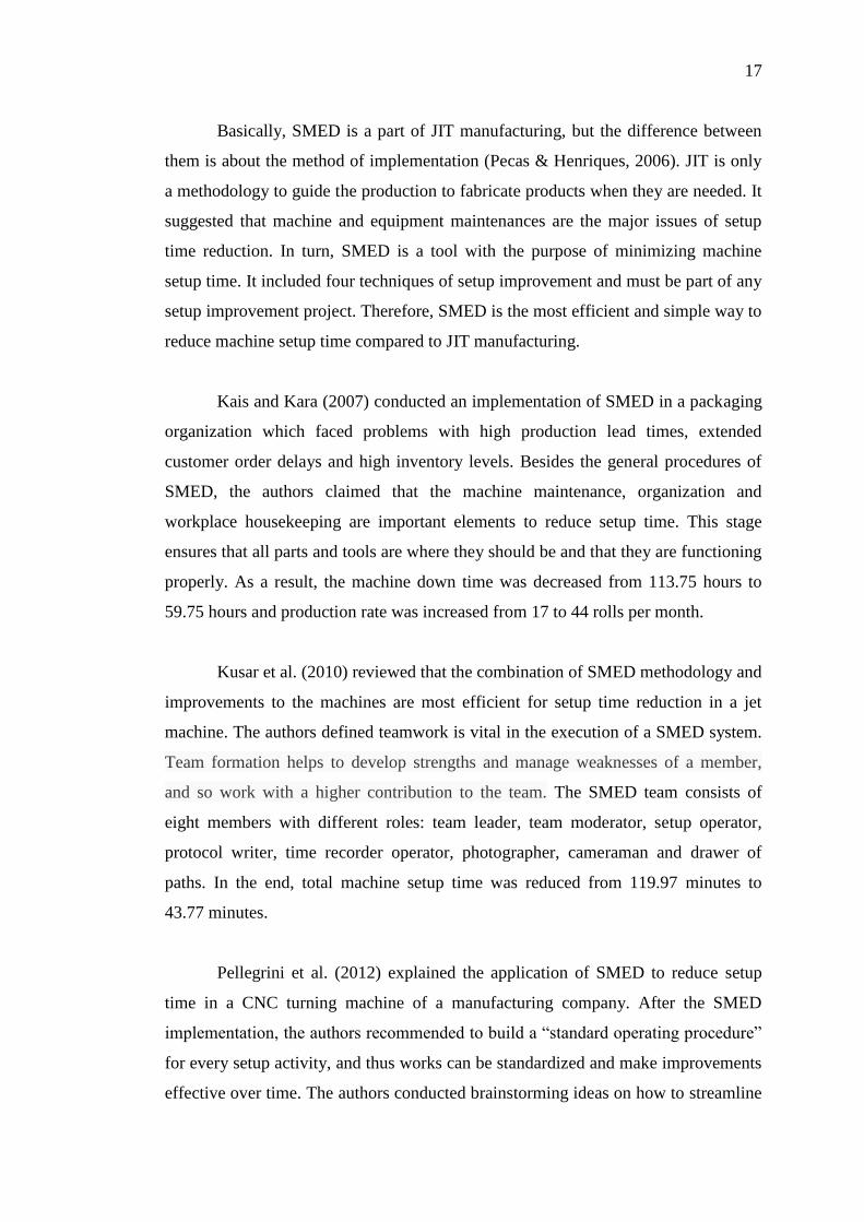
Basically, SMED is a part of JIT manufacturing, but the difference between
them is about the method of implementation (Pecas & Henriques, 2006). JIT is only
a methodology to guide the production to fabricate products when they are needed. It
suggested that machine and equipment maintenances are the major issues of setup
time reduction. In turn, SMED is a tool with the purpose of minimizing machine
setup time. It included four techniques of setup improvement and must be part of any
setup improvement project. Therefore, SMED is the most efficient and simple way to
reduce machine setup time compared to JIT manufacturing.
Kais and Kara (2007) conducted an implementation of SMED in a packaging
organization which faced problems with high production lead times, extended
customer order delays and high inventory levels. Besides the general procedures of
SMED, the authors claimed that the machine maintenance, organization and
workplace housekeeping are important elements to reduce setup time. This stage
ensures that all parts and tools are where they should be and that they are functioning
properly. As a result, the machine down time was decreased from 113.75 hours to
59.75 hours and production rate was increased from 17 to 44 rolls per month.
Kusar et al. (2010) reviewed that the combination of SMED methodology and
improvements to the machines are most efficient for setup time reduction in a jet
machine. The authors defined teamwork is vital in the execution of a SMED system.
Team formation helps to develop strengths and manage weaknesses of a member,
and so work with a higher contribution to the team. The SMED team consists of
eight members with different roles: team leader, team moderator, setup operator,
protocol writer, time recorder operator, photographer, cameraman and drawer of
paths. In the end, total machine setup time was reduced from 119.97 minutes to
43.77 minutes.
Pellegrini et al. (2012) explained the application of SMED to reduce setup
time in a CNC turning machine of a manufacturing company. After the SMED
implementation, the authors recommended to build a “standard operating procedure”
for every setup activity, and thus works can be standardized and make improvements
effective over time. The authors conducted brainstorming ideas on how to streamline

18
and improve both processes. By implementing SMED methodology, the machine
setup time was minimized from 1 hour and 25 minutes to 47 minutes.
Adanna and Shantharam (2013) researched that a setup time reduction in an
automobile equipment manufacturing organization by using SMED system. The
authors defined the SMED methodology as ECRS for this implementation. ECRS
process worked to eliminate unnecessary procedures, combine several processes to
save time, reduce several activities and simplify complex processes. In the end, the
firm reduced total setup time from 24.065 minutes to 14.416 minutes and machine
productivity was increased by 65.38%.
Stadnicka (2014) explored the system of SMED used in a CNC turning lathe
machine of a production company. The author combined SMED with risk analysis to
identify which operation may cause the risk of elongating the setup time and the
factors for low machine productivity. One of the risk analysis examples is failure
mode effects analysis (FMEA) used after the setup procedure analysis and after the
elimination of external activities. In addition, the author involved setup
standardization to reduce the repeatability of processes. After the SMED system, the
distance movement of operator was shortened from 110 meters to less than 15 meters.
The setup time reduced from 1 hour 12 minutes to 44 minutes which is equal to 38%
time saving.
Che Ani and Shafei (2015) reviewed SMED methodology to eliminate the
high changeover time during changing model in a CNC facility. The authors
introduced a conventional process, Plan-Do-Check-Act (PDCA) cycle that can be
worked with SMED method to get from “problem-faced” to “problem-solved”. It is
an iterative checklist of four steps from defined problem, executed plan, measured
outputs and lastly revised the plan. Furthermore, the authors purposed to use working
instruction and drawer tool cabinet to minimize setup errors and unnecessary
movements. Finally, the machine productivity was increased from 93% to 95.6% and
setup time reduced from 4 hours 9 minutes to 2 hours 58 minutes.

19
2.5 Jig and fixture design
Jigs and fixtures are the essential tools which are used to facilitate manufacturing
repetitive components within defined tolerances. Generally, it is designed to fabricate
large batch size of identical parts and ensuring interchangeability of products. Jig is a
work holding tool that supports a workpiece and gives a direction to cutting tool for
the desired manufacturing operations (Nanthakumar & Prabakaran, 2014). A fixture
similar to a jig, the difference is fixture does not guide a cutting tool for the
operations (Kaija & Heino, 2006). Fixtures will only provide a reference surface to
the workpiece and each fixture is built only for a specific product.
Jigs and fixtures decrease machine setup time and increase productivity by
reducing the tasks of marking, orientating, alignment, levelling and setting for each
workpiece. The high precision of jigs and fixtures design facilitates the production of
large batches of products with high accuracy of dimension and high quality.
Furthermore, jigs and fixtures are used to standardize the setup procedures and thus
unskilled or semi-skilled machine operator can easily use the fixtures. By using jigs
and fixtures, some heavy and complex design of parts can be readily machined after
clamping. From all the listed advantages above, it leads to the reduction of labour
cost, rework and product inspection.
When implementing SMED tool, the converting of internal to external setup
is the most important stage to reduce machine setup time significantly. In other
words, SMED implementation will considers as an unsuccessful activity when the
conversion stage is fails. Next, SMED is difficult to apply when all steps of the
current process are external setups. Thus, jig and fixture was introduced as a tool to
eliminate internal setup and further reduce external setup time. In addition, SMED
required a long period of time to conduct the four conceptual stages whereas jig and
fixture is always designs according to the workpiece structure, clamps and supporters
(Joshi, 2010).
Hunter et al. (2005) described the process of machining jigs and fixtures
design to reduce machine setup time. The authors claimed that jigs and fixtures are
20
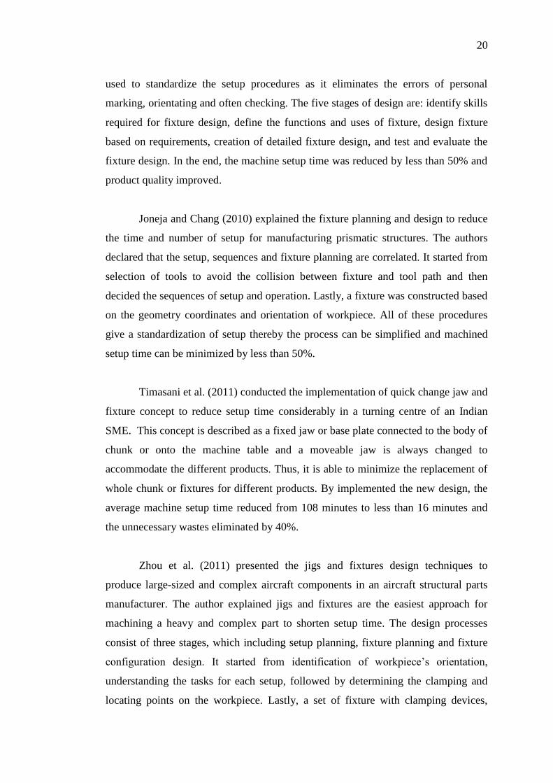
used to standardize the setup procedures as it eliminates the errors of personal
marking, orientating and often checking. The five stages of design are: identify skills
required for fixture design, define the functions and uses of fixture, design fixture
based on requirements, creation of detailed fixture design, and test and evaluate the
fixture design. In the end, the machine setup time was reduced by less than 50% and
product quality improved.
Joneja and Chang (2010) explained the fixture planning and design to reduce
the time and number of setup for manufacturing prismatic structures. The authors
declared that the setup, sequences and fixture planning are correlated. It started from
selection of tools to avoid the collision between fixture and tool path and then
decided the sequences of setup and operation. Lastly, a fixture was constructed based
on the geometry coordinates and orientation of workpiece. All of these procedures
give a standardization of setup thereby the process can be simplified and machined
setup time can be minimized by less than 50%.
Timasani et al. (2011) conducted the implementation of quick change jaw and
fixture concept to reduce setup time considerably in a turning centre of an Indian
SME. This concept is described as a fixed jaw or base plate connected to the body of
chunk or onto the machine table and a moveable jaw is always changed to
accommodate the different products. Thus, it is able to minimize the replacement of
whole chunk or fixtures for different products. By implemented the new design, the
average machine setup time reduced from 108 minutes to less than 16 minutes and
the unnecessary wastes eliminated by 40%.
Zhou et al. (2011) presented the jigs and fixtures design techniques to
produce large-sized and complex aircraft components in an aircraft structural parts
manufacturer. The author explained jigs and fixtures are the easiest approach for
machining a heavy and complex part to shorten setup time. The design processes
consist of three stages, which including setup planning, fixture planning and fixture
configuration design. It started from identification of workpiece’s orientation,
understanding the tasks for each setup, followed by determining the clamping and
locating points on the workpiece. Lastly, a set of fixture with clamping devices,

21
locating devices and base plate is produced. After the implementation, the machine
setup time was decrease by 90% and the complex structures were machined easily.
Pattantyus (2013) implemented the jig design and shadow board techniques
to reduce setup time in a manufacturing firm. Before the improvement, the operators
used much time to set and cut different standard dimension of bar stock and each of
the stop distance is measured by measuring tape. Then, the author built simple jigs
with standard cut dimensions to simplify the setting process. Furthermore, a shadow
board was designed to store all the jigs, thereby eliminating the waste of motions to
get the setup tools. As a result, the productivity was improved as a consequence of
reduction in setup time.
Okpala and Okechukwu (2015) reviewed the importance and elements of jigs
and fixtures in manufacturing operations in order to reduce machine setup time. In
the structures of jig and fixture, clamping and locating devices are the major
concerns of design because both are controlling the right orientation of workpiece.
Clamping devices used to apply pressure and hold the workpiece against the locating
devices, and thus fix it in the right direction for the cutting tool. The locating devices
such as pin and supporter, are designed to easily locate the orientation of workpiece.
The authors emphasized that jigs and fixtures are used to minimize the tasks of
dimension checking, orientating, marking, punching, levelling and alignments.
Therefore, the machine setup time can be reduced.

22
Table 2.1: Practices or techniques associated in setup time reduction
Setup Tools Practices Kaizen literature JIT literature SMED literature Jig & fixture design literature
1 2 3 4 5 6 7 8 9 10 11 12 13 14 15 16 17 18 19 20 21 22 23 24
Kaizen SWOT √
Kaizen SAP √
Kaizen Simulation √ √
JIT TPM √ √ √ √ √
SMED Machine maintenance √ √
SMED Team formation √ √
SMED SOP √
SMED PDCA cycle √ √
SMED FMEA √
Jig & fixture design Setup planning √ √
Jig & fixture design Quick change jaw & fixture √
Common Organization & housekeeping √ √ √ √ √
Common Brainstorming √ √ √ √
Common 5S √ √ √ √
Common ECRS √ √
Common Standardization √ √ √ √ √ √ √ √ √ √
Common Process improvement √ √
References: (1) Burns (2000); (2) Lee (2000); (3) Dehghan et al. (2006); (4) Upadhye et al. (2010); (5) Rajenthirakumar and Thyla (2011); (6)
Adams et al. (2014); (7) Schroeder et al. (2001); (8) Fullerton et al. (2002); (9) Ahmed et al. (2005); (10) Doolen and Hacker (2005); (11) Landry
(2008); (12) Dowlatshahi and Taham (2009); (13) Kais and Kara (2007); (14) Kusar et al. (2010); (15) Pallegrini et al. (2012); (16) Adanna and
Shantharam (2013); (17) Stadnicka (2014); (18) Che Ani and Shafei (2015); (19) Hunter et al. (2005); (20) Joneja and Chang (2010); (21)
Timasani et al. (2011); (22) Zhou et al. (2011); (23) Pattantyus (2013); (24) Okpala and Okechukwu (2015)

23
2.6 Findings of literature review
This review shows Kaizen is the most common tool of setup time reduction. There
are many research conducted based on the Kaizen philosophy to improve their
overall production performance. This concept is widely used by most of the
manufacturing industries because (1) it can be implanted to any improvement process,
(2) it required less investment in equipment or facility to achieve the desired outcome
and (3) it involved each employee in process of change. Moreover, jig and fixture
design is the least employed method to minimize machine setup time. In the past,
there are few study performed which relates to jig and fixture design for the purpose
of reducing setup time. The reasons are (1) jig and fixture may difficult to design for
complicated process, (2) it only valid to use for certain product and (3) extra raw
materials and times are required to fabricate a jig and fixture.
As mentioned in the previous sections, the main focus of Kaizen is to
improve employee performances for solving various organization problems. JIT
promoted “right first time” concept to eliminate waste of motion of operator, so the
machine setup time can be reduced. Between the two methods, JIT is better to apply
in setup time reduction. On the other hand, SMED is a tool that clarified with four
important techniques to perform in any setup improvement projects. Thus, SMED is
more efficient to minimize setup time compared to JIT. Sometimes, SMED is fails to
implement when the whole setup process is consists of external setups. Then, jig and
fixture is a more useful tool compared to SMED as it can eliminates internal setup
and further reduce external setup time.
Compared to jig and fixture design, Kaizen is less effective to reduce
machine setup time. In all the Kaizen literature, it only build a concept of “change for
better” but does not include any specific techniques or methods for setup
improvement. Jig and fixture is a solid body to simply and standardize the setup
processes and easier to use by operator. Secondly, Kaizen is difficult to implement
since it always encouraged top management and employees work in a team and
conduct brainstorming to solve problems. For jig and fixture, few of employees are
only required to involve in the design process. In addition, Kaizen is an extremely
time-consuming method as a long time required for monitoring and maintaining after

24
the implementation. By implementing jig and fixture, a significant improvement can
be obtained immediately as the setup process is simplified.
Similarly, the involvement of employees is the main difference between jig
and fixture design and JIT. With a jig and fixture implementation, it can save a lot of
times and also avoids to get into a heated argument between top management and
operators. Furthermore, the setup improvement methods that proposed by JIT are
eliminate waste of motion and perform machine maintenance. These methods may
not applicable for some industries if there is no waste of motion or machine
performance is maintains well. Therefore, jig and fixture is better than JIT since it
works directly with a workpiece and has a high flexibility in design based on the
workpiece structure.
In fact, Kaizen, JIT and SMED are difficult to achieve a significant
improvement if jig and fixture is not used in the manufacturing process. The primary
premise of setup time reduction is designs a special tool to simplify or eliminate any
unnecessary setup steps. Kaizen, JIT and SMED focuses on the elimination of raw
materials and tools preparation process. For jig and fixture, it started with a study of
workpiece structure to determine the best way of setup and machining processes. It
functions to position and fix the orientation of workpiece to make the workpiece
adjustment easier and simplify the setup procedures.
Among the four setup methodologies, jig and fixture design is the most
efficient method for machine setup time reduction. Firstly, it is more simple and cost-
effective to invest in the entire production process. This method does not required
high involvement of all employees, whereas the design of jigs and fixtures are fully
depend on the sequences of operation and capacity of that machine. The design
considerations of jig and fixture are referred as guidelines during the design process
and thus making the jig and fixture less costly.
Meanwhile, jig and fixture is the best tools in mass production to maintain a
low product rejection rate due to high and uniform quality of goods are produced.
Since the product quality is consistent and maximized, the inspection activities can
be eliminated and high amount of time was saved. Furthermore, use of jig and fixture

25
make a high standardization and efficiency of work and thus setup procedures were
simplified. Next, jig and fixture offers a good and easy way for operator to position a
workpiece onto the machine in minimum time.
26
CHAPTER 3
3 METHODOLOGY
3.1 Introduction
As shown in Figure 3.1, this research started with literature review. Important
theories and relevant findings were studied and summarized. The research
framework was developed based on a case study in Company “X”. A high demand
product was selected for setup improvement. Definition of target setup time gives an
encouragement to conduct improvement. The setup procedures were studied
carefully and analysed to identify underlying problems of current setup. Some of the
processes were eliminated by redesign the existing jigs and fixtures. After the new
jig fabrication, an improved analysis was conducted again.

27
Figure 3.1: Flow chart

28
3.2 Selection of product and process
In the first stage, a product was selected for reduction of machine setup time by
considering the predefined criteria such as longest machine setup time, high demand
product, frequency of setups and bottleneck of processes. A short period of
observation (1 week) was carried out to define the products which have long setup
time (more than one hour). Next, the first three highest demand products were chose
from the defined items. From these three items, a product with largest frequency of
setup (per day) was selected as the focus of this thesis. If the final selected product is
consists of more than one machining steps, the bottleneck of processes was
determined based on the setup time of each step. From the result of observation, this
research focused on a reduction of setup time for first machining step of product “Y”.
The reasons for this selection are: longer setup time, one of the high demand
products for Company “X” and first step is the bottleneck of processes.
3.3 Definition of target setup time
Kusar et al. (2010) described that the definition of target setup time is important and
it acts as a motivation for the implementer to perform a better setup improvement.
Generally, manufacturing industries required their employees to eliminate the
machine setup time by 50% of current value during the first round of implementation.
From the basic steps in setup procedure, the 50% of total setup time is belongs to the
trial runs and adjustments operation. The length of this operation depends on the skill
of operator to adjust the equipment accurately. Therefore, the proportion of time for
this operation is easier to minimize by increasing the precision of the equipment. In
this research, the target time needed for setup can be reduced by 25% to 50% of the
current setup time.

29
3.4 Documenting elements of current machine setup
After determining the target time, a time motion study was conducted on the current
machine setup process. The sequences and exact time required for each setup step are
identified and measured. A list with the details of setup procedure is a common tool
for recording the sequences and execution time of machine setup. All the elements
and microelements of setup are listed in the notes, which include the actual
sequences of the machine setup with the exact time needed. After recording the
elements of setup, the data will be arranged into the monitoring paper. The
monitoring paper is a form that contained all the necessary information for assessing
and controlling the current machine setup. The data included the sequence number, a
brief description, individual time and histogram of task times for each machine setup
step.
After the time study, a motion study was conducted to define wastes of
motion of machine setup operator. A list of paths is prepared based on the floor plan
of workplace. The movements of the operator during setup are drawn onto the list of
paths with a continuous line. According to the continuous analysis of machine setup
elements and the list of paths moved by setup operator, all the unnecessary
movements can be eliminated and created a new motion path. Then, a high-definition
camera was used to take photos of machine setup procedure in detail. The photos
helped to visualize the actual setup process instead of words.
An additional tool is a video camera, to videotape the entire machine setup.
The film started to record at the beginning of first setup procedure until the end of
last process. Therefore, the whole setup procedures can be reviewed several times
and analysed effectively. The video film was shown to the operators for providing
them an opportunity to point out their opinions which lead to useful suggestions. In
many cases, these suggestions can be adopted on the spot.

30
3.5 Analysis of current machine setup procedure
In this section, the current machine setup operation was analysed and discussed.
Product “Y” is consists of three machining steps, where the first step is the
bottleneck among the others. Based on the data collected, the total setup time for
product “Y” is 1.65 hours and all the time consuming procedures are related to the
available jig and fixture. The setup steps are involved: machine cleaning, load and
position jigs onto the machine, lifting workpiece onto the jigs, conduct levelling
along z-axis, alignment along x and y-axis and set a centre point of workpiece.
The highest time consumed in current setup method is loading and adjusting
the distance between two pieces of jigs onto the machine table to fix the position and
height of the workpiece. After the jigs loading, the operator conducted workpiece
levelling in z-axis direction and ensured the correct alignment along x and y-axis
positions. This process repeated several times until the workpiece was located
correctly. All the steps listed above are potentially to simplify or eliminate in this
research.
The suggestion for a new jig and fixture is consists of four locators and four
clamps, and each locator is placed nearby the clamp. Since there is no changing part
of the jig, all the components are welded on the base plate according to the
dimensional requirements. Due to the locating problem of jig on machine bed, step
clamp, step block and flange nut were used to clamp the jig in a precise location onto
the machine table.
3.6 Jig and fixture redesign using improvement of current machine setup
Before started the redesign process, there are a lot of design considerations in jig and
fixture. The main structure of jig and fixture must be strong and tough to withstand
the clamping force and machining vibrate, so that prevented the deformation of jig
and fixture. It suggested that the jig and fixture can be constructs from simple
sections, and then connected the parts with welded or screws. If the parts are

31
constantly fastened with the jig, it may be welded, otherwise, the parts can be
screwed onto the jig for frequent removing.
The main design consideration in clamping components is the capability to
resist the forces developed vibration during the machining process. In addition, the
position of clamps should be located nearby the strongest clamping force, which is
the supported part of workpiece. If the clamping works on unsupported part, the
workpiece will be bends and influences the accuracy of workpiece dimension.
Basically, the locations of clamps are not designed to hinder the path of workpiece
loading and unloading.
Locating elements are described as placing the workpiece correctly with
respect to dimensional requirements of the workpiece. Firstly, the locator was
designed by considering the easiest way to load and unload workpiece with
minimum movements and efforts. After loading the workpiece onto the locators, it is
securely engaged with clamps to ensure no motion around and along x, y and z-axis.
In order to make the setup easier, redundant locator is avoids to build onto the jig and
fixture. Redundant locators are locators provided are more than the number of
locators required. In this research, the new jig and fixture was redesigned by
referring the considerations listed above.
3.7 Validation of jig and fixture design
Before fabrication of new jig and fixture, the proposed design was verified and
validated by the supervisor of “Company X”. Firstly, the supervisor reviewed the
drawing of jig and fixture to examine the dimension of structure with high accuracy.
Next, the 2D drawings of jig and workpiece are combined by using AutoCAD to test
and ensure all the locators and clamps are not obstructed the machining path of
workpiece. Thirdly, the strongness and toughness of each component in jig and
fixture were checked based on its thickness or diameter. This is to ensure the
redesign structure is capable to resist clamping force and machine vibration. Lastly,
32
the new jig and fixture must be validated in each machine (either in horizontal or
vertical direction of machine bed).
3.8 Time study of proposed jig and fixture after fabrication
According to the AutoCAD drawing generated in the previous stage, the new jig and
fixture was fabricated through CNC machining, assembly and welding processes. To
be success in the new jig and fixture, a precision tolerance detailed machining is
required for the entire fabrication process. By using the redesigned jig and fixture, a
time motion study was performed on the improved jig and fixture to measure the
degree of improvement. All the tools stated in 3.4 were used to record the details of
improved machine setup.

33
CHAPTER 4
4 RESULTS AND DISCUSSIONS
4.1 Introduction
The background information and uses of product “Y” were explained in the first part
of this chapter. Next, the current setup and machining processes were presented. The
setup processes were analysed and few suggestions were proposed in order to
simplify or eliminate the bottleneck procedures. In this chapter, the function of each
component in the redesigned jig was discussed. Five considerations in validating the
redesigned jig were listed and explained. Time study of redesigned jig showed that
the machine setup time was improved. Lastly, the time required for return on
investment (ROI) was determined.
4.2 Setup process of product “Y”
“Y” is a component of crane spreaders, welded at the top and middle of its main
body. After assembly, the spreaders are put into services to handle shipping
containers. One example of its usage is in the lifting arm of a Kalmar reach stacker
forklift (Figure 4.1). This equipment effectively solved cargo handling problems and
is use in terminals, ports, heavy industries and distribution centres. The function of
“Y” is designed to improve the flexibility and increase driving efficiency of a reach
stacker forklift. It helps to rotate and tilt a container for easy and quick handling in

34
any situation. Therefore, the forklift has the smallest turning radius in the facility for
better manoeuvring in narrow spaces.
Figure 4.1: Kalmar reach stackers forklift (from www.gs-limited.net)
The spreader can be rotated in any direction since a gearwheel is connected
between “Y” and the body of spreader (Figure 4.2). Then, a container can be rotated
and shipped lengthwise to transport it into and through cramped spaces (Figure 4.3).
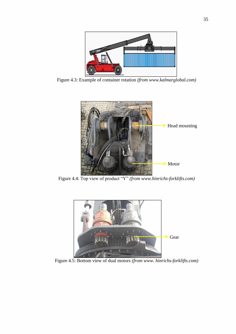
In Figure 4.4 and 4.5, dual motors are attached on “Y” to supply energy and gears are
installed at the bottom of motors to control the movement of spreader rotation. The
head mounting of “Y” is linked with the lifting arm to tilt the spreader at an angle to
the side (Figure 4.4). Referring to Figure 4.6, the tilt feature enables easy container
loading for the convenience of operations.
Figure 4.2: Side view of product “Y” (from www.hinrichs-forklifts.com)
Gearwheel
Product “Y”
Product “Y”
Body of spreader
35
Figure 4.3: Example of container rotation (from www.kalmarglobal.com)
Figure 4.4: Top view of product “Y” (from www.hinrichs-forklifts.com)
Figure 4.5: Bottom view of dual motors (from www. hinrichs-forklifts.com)
Head mounting
Motor
Gear

36
Figure 4.6: Lilt container at an angle (from www.kalmarglobal.com)
In Company “X”, “Y” is a high demand product. The production operated 8
hours/shift, 2 shifts/day, 6 days/week and 45 weeks/year. From the past records, the
average monthly demand for product “Y” is 20 units and the current daily production
rate for a completed “Y” is one unit. In theory, if the product consists of more than
one manufacturing operation, the batch size is minimized as small as possible to
avoid scheduled delay at the next process. Therefore, the setup frequency becomes
higher as batch size is reduced. As the total required processing time for a completed
“Y” was 11.15 hours, the minimum frequency of setup is one per day, in order to
meet the customer demand.
To have a finished product “Y”, three machining steps with different
procedures are required. The machine that is used to produce “Y” is called Agma Six
Meters Double Column Machining Centre (Figure 4.7). The size of the machine is
6200mm length and 2800mm width. In Step 1, the setup processes consist of
cleaning machine, loading and positioning two pieces of jigs onto machine, lifting
workpiece, levelling along z-axis, alignment along x and y-axis and setting a centre
point of workpiece. The average setup time required for this step was 1.65 hours. For
Step 2 and 3, the setup processes are similar but different types of jig are used. The
processes included: cleaning machine, loading and positioning jigs, lifting workpiece
and setting a centre point. The setup time for Step 2 was 1.22 hours and for Step 3
was 1.03 hours.

37
Figure 4.7: Machine operated for processing “Y”
In setup of step 1, the bottleneck procedures are loading and positioning the
jigs, workpiece levelling and alignment in different axes. For the process of jigs
positioning, the operator measured and maintained a constant distance between the
two pieces of jigs to support the corners of “Y”. During the levelling and alignment
procedures, the operator repeated the measurements several times in order to have a
correct position of the workpiece. The overall setup time of these three procedures
was 0.87 hour. In step 2, the procedure with longest setup time was loading and
positioning the jigs. Similarly, a distance was measured and adjusted as two pieces of
jigs were used in this step. The time that consumed in this process was 0.42 hour. For
step 3, the largest setup time procedure was workpiece positioning which used 0.33
hour to ensure a right orientation of workpiece. In this process, the operator spent a
lot of time to screw 12 pieces of flange nuts to the clamps onto the jig.
The machining processes for Step 1 involved: surface milling, boring, point
marking, drilling, chamfering and tapping. The average machining time was 3.25
hours. For Step 2, the processes included drilling, roughing and boring. This step was
spent 2.67 hours for machining. The process of Step 3 is milling 2 slots of Ø280mm,
and it takes 1.33 hours to complete the machining.
In summary, the setup time percentages of total processing time per unit are
14.8% for Step 1, 10.94% for Step 2 and 9.24% for Step 3. The highest percentage
and largest processing time in Step 1 indicate that this stage is the bottleneck of
processes and having longer setup time compared to Step 2 and Step 3. All the data
are summarized in Table 4.1.

38
Table 4.1: Average time required for each process of product “Y”
Step Average
Setup Time,
TS (hours)
Average
Machining
Time, TM
(hours)
Average Total
Required Time,
TP = TS + TM
(hours)
Percentage of Setup
Time per Unit, ( X
100%)
1 1.65 3.25 4.90 14.80 %
2 1.22 2.67 3.89 10.94 %
3 1.03 1.33 2.36 9.24 %
Total 3.90 7.25 11.15 34.98%
4.3 Target setup time reduction
Referring to section 4.2, there are three bottleneck procedures in Step 1 and both
show potential to be modified by redesigning the jig and fixture. In the current setup,
two pieces of jigs are used and are involved in all the steps. By redesigning the
structure of jig, the improvements can be significant. Firstly, the jigs positioning
process can be simplified by reducing the number of jigs to one piece. Therefore, the
jigs loading time can be decreased from 0.4 to approximately 0.2 hour and eliminate
the distance adjustment step between the two pieces of jigs. Secondly, the levelling
and alignment processes can be streamlined by designing additional locators. The
new locator acts as a reference point for operator to place the workpiece in parallel or
perpendicular position corresponding to the machine table. Thus, the setup time for
levelling and alignment processes can be reduced from 0.47 to approximately 0.24
hour.
Table 4.2: Target value of setup time reduction
Procedures
Current
setup time
(hour)
Target
setup time
(hour)
Time
reduced
(hour)
Loading and positioning jigs onto machine 0.40 0.20 0.20
Levelling along z-axis 0.27 0.14 0.13
Alignment along x and y-axis 0.20 0.10 0.10
Total 0.87 0.44 0.43

39
0.43
1.65
By completing the listed improvement methods above, the overall setup time
is estimated to reduce from 0.87 hour to 0.44 hour. By applying some simple
calculation, the minimum percentage for reduction is 26.06% of the current setup
time. In this research, the target is set to reduce setup time by 25% to 50% of current
value.
Average current machine setup time = 1.65 hours
Minimum percentage of setup time reduction = X 100%
= 26.06%
4.4 Elements of current machine setup
During the time motion study, all setup tasks are listed according to its sequences and
the exact time are recorded. Since all the machines operated in Company “X” are
semi-automated, the time required for each process may vary when operated by
different people. A total of eleven (1 set from initial observation and 10 sets for
calculating the mean setup time) data sets were collected to increase the tendency to
cluster around a certain value. Then, the mean and standard deviation of each setup
process were calculated and listed in the monitoring paper (Table 4.3). Mean serves
as a central value for all data collected. Standard deviation shows the degree of
dispersion of the data from the average. As shown in Table 4.3, the alignment
process has the highest dispersion or variability in its setup task time. This is
followed by machine cleaning and jigs loading. An example of eleven data for
alignment process was shown in Chart 4.1.
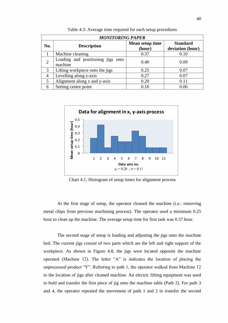
40
0
0.1
0.2
0.3
0.4
0.5
1 2 3 4 5 6 7 8 9 10 11Me
an s
etu
p t
ime
(h
ou
r)
Data sets no.µ = 0.20 ; σ = 0.11
Data for alignment in x, y-axis process
Table 4.3: Average time required for each setup procedures
MONITORING PAPER
No. Description Mean setup time
(hour)
Standard
deviation (hour)
1 Machine cleaning 0.37 0.10
2 Loading and positioning jigs onto
machine 0.40 0.09
3 Lifting workpiece onto the jigs 0.25 0.07
4 Levelling along z-axis 0.27 0.07
5 Alignment along x and y-axis 0.20 0.11
6 Setting centre point 0.16 0.06
Chart 4.1: Histogram of setup times for alignment process
At the first stage of setup, the operator cleaned the machine (i.e.: removing
metal chips from previous machining process). The operator used a minimum 0.25
hour to clean up the machine. The average setup time for first task was 0.37 hour.
The second stage of setup is loading and adjusting the jigs onto the machine
bed. The current jigs consist of two parts which are the left and right support of the
workpiece. As shown in Figure 4.8, the jigs were located opposite the machine
operated (Machine 12). The letter “A” is indicates the location of placing the
unprocessed product “Y”. Referring to path 1, the operator walked from Machine 12
to the location of jigs after cleaned machine. An electric lifting equipment was used
to hold and transfer the first piece of jig onto the machine table (Path 2). For path 3
and 4, the operator repeated the movement of path 1 and 2 to transfer the second
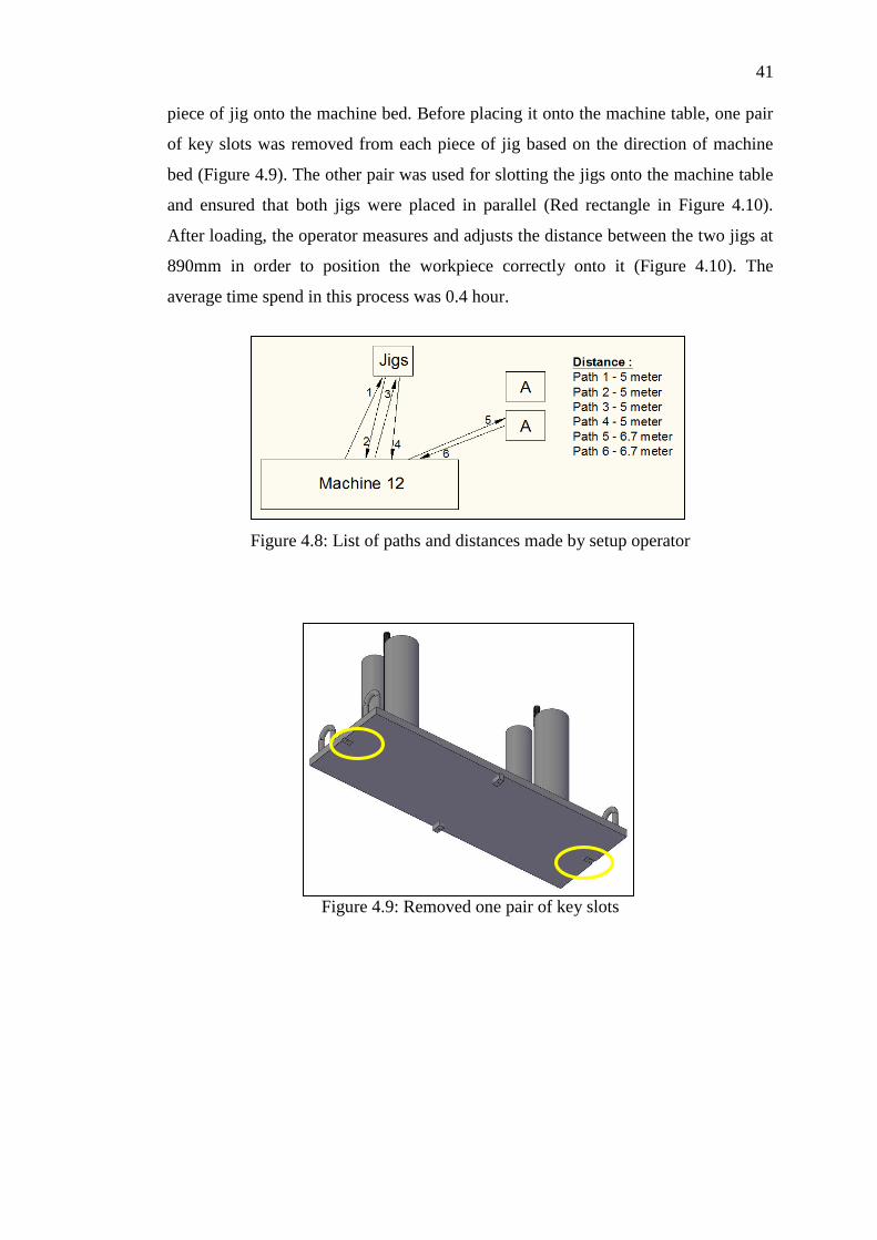
41
piece of jig onto the machine bed. Before placing it onto the machine table, one pair
of key slots was removed from each piece of jig based on the direction of machine
bed (Figure 4.9). The other pair was used for slotting the jigs onto the machine table
and ensured that both jigs were placed in parallel (Red rectangle in Figure 4.10).
After loading, the operator measures and adjusts the distance between the two jigs at
890mm in order to position the workpiece correctly onto it (Figure 4.10). The
average time spend in this process was 0.4 hour.
Figure 4.8: List of paths and distances made by setup operator
Figure 4.9: Removed one pair of key slots

42
Figure 4.10: Arrangement of jigs onto the machine
The third stage is loading the workpiece by lifting equipment and placing it
onto the jigs (Figure 4.11). Referring to Figure 4.8, product “Y” is placed beside the
machine operated (Machine 12). After the jigs loading and distance setting, the
operator moved from machine to the placement of “Y” (Path 5). The path 6 indicated
the movement of workpiece transferred from its original place onto the machine.
Four pieces of step clamps and flange nuts were tightened to the clamps around the
corners of jigs. For the first round of workpiece clamping, the nuts were not
tightened fully in order to adjust the correct position of workpiece during the
levelling and alignment procedures. For this stage, the average setup time was 0.25
hour.
Figure 4.11: Placement of “Y” onto the jigs
The fourth stage is to conduct workpiece levelling along the z-axis for
checking the surface flatness of bottom plate of “Y”. The purpose of levelling is to
minimize the distortion effects of preceding processes for improving the positioning
890 mm
Slotted by
pair of key
slots
Step clamp
Flange nut
Clamp
Support
Locator

43
accuracy of workpiece. To form a completed structure of “Y”, a lot of components
were welded together according the required dimensions (Figure 4.12). When a
material or part is cut or assembled by any thermal processes, it will cause
temperature difference within the workpiece and leads to thermal distortion at its
surface as the workpiece cools (Figure 4.13). Thus, the workpiece will not be
perfectly flat. A dial indicator was used to conduct flatness measurement. The uses of
flatness measurement are divided into two categories: positioning and resurfacing of
workpiece.
Figure 4.12: Components to form a “Y” (from www.hinrichs-forklifts.com)
Figure 4.13: Occurrence of thermal distortion (from www.hinrichs-forklifts.com)
Component 1
Component 2
Component 3
Component 4 Component 5 Component 6
Component 7
Component 8
Component 9
Component 10
Thermal
distortion on
bottom plate
of “Y”
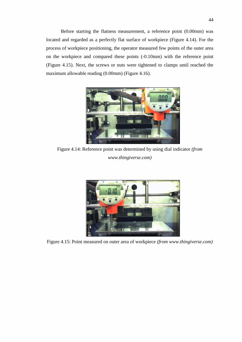
44
Before starting the flatness measurement, a reference point (0.00mm) was
located and regarded as a perfectly flat surface of workpiece (Figure 4.14). For the
process of workpiece positioning, the operator measured few points of the outer area
on the workpiece and compared these points (-0.10mm) with the reference point
(Figure 4.15). Next, the screws or nuts were tightened to clamps until reached the
maximum allowable reading (0.00mm) (Figure 4.16).
Figure 4.14: Reference point was determined by using dial indicator (from
www.thingiverse.com)
Figure 4.15: Point measured on outer area of workpiece (from www.thingiverse.com)
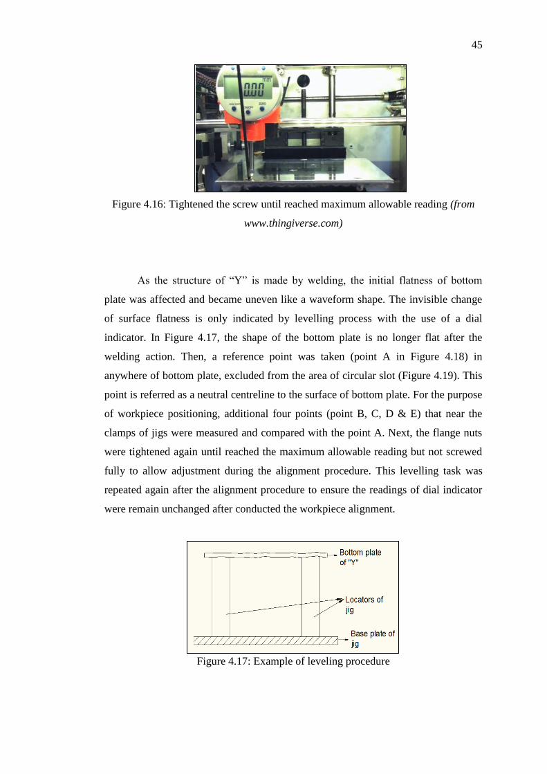
45
Figure 4.16: Tightened the screw until reached maximum allowable reading (from
www.thingiverse.com)
As the structure of “Y” is made by welding, the initial flatness of bottom
plate was affected and became uneven like a waveform shape. The invisible change
of surface flatness is only indicated by levelling process with the use of a dial
indicator. In Figure 4.17, the shape of the bottom plate is no longer flat after the
welding action. Then, a reference point was taken (point A in Figure 4.18) in
anywhere of bottom plate, excluded from the area of circular slot (Figure 4.19). This
point is referred as a neutral centreline to the surface of bottom plate. For the purpose
of workpiece positioning, additional four points (point B, C, D & E) that near the
clamps of jigs were measured and compared with the point A. Next, the flange nuts
were tightened again until reached the maximum allowable reading but not screwed
fully to allow adjustment during the alignment procedure. This levelling task was
repeated again after the alignment procedure to ensure the readings of dial indicator
were remain unchanged after conducted the workpiece alignment.
Figure 4.17: Example of leveling procedure

46
Figure 4.18: Reference points during workpiece positioning procedure
Figure 4.19: Example of circular slot with 0.2mm depth from reference point
In the workpiece resurfacing process, the operator may measures any point on
the part based on the area of resurfacing. The purpose of resurfacing is to ensure the
workpiece has an ideal surface flatness after any thermal processes. This can be done
by using dial indicator to determine the required depth of cut and generated G-code
to define the Z motion dimension. Referring to Figure 4.20, the first gauge indicated
the point measured was 0.002 inches higher than the reference point whereas the
second gauge shown the other point was 0.003 inches lower than the reference point.
In order to have a flat surface of workpiece, the ideal depth for resurfacing was 0.003
inches from the reference point.
Circular slot

47
Figure 4.20: Example of flatness measurements using dial indicator (from
www.pmpa.org)
The levelling measurement was also applied for the resurfacing of circular
slot on the bottom plate. This slot is used to fix the gearwheel for spreader rotation.
Referring to Figure 4.21, the point F, G and H obtained different value from
centreline since different portions of plate were compressed or stretched about its
centreline. The measured values of F, G and H are used to decide the depth of cut for
milling the circular slot. The operator assigned the z-coordinate of largest indication
value (point H) as the z-axis coordinate of centre point. Based on the dimension
requirement in product “Y”, the depth of circular slot cannot be more than 0.2mm
with respect to the level of reference point (point A). The operator used G-code to
finalize the depth of cut be Z-0.8. The average setup time for the whole levelling
procedures was 0.27 hour.
Figure 4.21: Reference points during workpiece resurfacing procedure

48
The fifth stage of setup is performing alignment of the workpiece along x and
y-axis positions. This action is to ensure the workpiece is placed in parallel and
perpendicular to jigs and machine bed. Similarly, this process is carried out by using
dial indicator. As shown in Figure 4.22, the dial indicator was placed at the centre
bore of product “Y” to align the workpiece position. The dial indicator was moved
along from point 1 to 2 with several times until the dial indicator shows a constant
reading. After finished alignment, the nuts were tightened fully to fix the position of
workpiece. The average setup time for this stage was 0.2 hour.
Figure 4.22: Conduct workpiece alignment by using dial indicator
The last setup process in Step 1 is locating a centre point of workpiece by
using edge finder. This tool is widely used to determine the edges and thus the centre
of workpiece can be easily located. The operator used edge finder to spindle around
the back side of the bore (point 3 in Figure 4.23) on y-axis until the cylinder body
runs off to the side (Figure 4.24). It continues to move towards the front edge of the
bore (point 4) and so the midpoint of y-axis is defined by the machine. The same
procedure was repeated on x-axis (point 5 & 6) and the midpoint of x-axis is
determined. Lastly, the operator identified the centre values of x and y-axis and reset
these coordinates be (0, 0) as the centre point of workpiece. The required time for
this process was 0.16 hour.
Point 1
Point 2

49
Figure 4.23: Point located to determine centre point of workpiece
Figure 4.24: Example of cylinder body of edge finder runs off to the side (from
www.tormach.com)
4.5 Analysis of current machine setup procedure
Referring to section 4.4, there are six setup procedures in Step 1 and three out of six
procedures are considered as bottleneck processes. The three bottleneck procedures
are: loading and positioning of jig and fixture, workpiece levelling along z-axis and
aligning the workpiece in parallel or perpendicular to x-axis and y-axis. All three
procedures are conducted with the available jig and fixture and used 0.87 hour which
equals to 52.7% of the total setup time. Therefore, the best method to reduce machine
setup time is redesign the current jig and fixture that is able to simplify or eliminate

50
the three bottleneck procedures listed above. The other three procedures are also
important but the time required cannot further reduce as both were operated without
related to the jig and fixture.
4.5.1 Loading and positioning of jig and fixture
The second stage of setup is started with loading the two pieces of jigs and fixtures
onto the machine. From Figure 4.25a, it shown that the operator moved four times to
transfer the two pieces of jigs from its location to the machine operated and total
distance travelled was 20 meters. Before placing the jigs onto the machine table, one
pair of key slots was removed from the bottom of each piece of jig and thus two pairs
of key slots were removed from the current jigs and fixtures. For the current jigs, it is
only used on certain machines as the size of key slot on bottom of jigs is same with
the size of T-slot table. Besides, the internal and external thread of key slot and screw
are subjected to wear because of the frequent removing and tightening of the screw
to the key slot. The average time required for this process was 0.35 hour. When the
jigs were ready on the machine, the operator measure and adjust the jigs in a distance
of 890mm to support the periphery of workpiece. The mean time used for
measurement was 0.05 hour. With a detailed analysis, the machine setup time can be
reduced by restructuring the processes of jigs loading, key slot removing and
distance measuring.
The first suggestion for redesigning a jig and fixture is to combine the two
jigs to one. With one piece of jig and fixture, the number of paths moved by operator
for jig loading can be reduced from 4 to 2 times and the distance travelled is
minimizes from 20 to 10 meters (Figure 4.25). Besides, the process of key slot
removing can be eliminated by changing the method of jig positioning. In the
redesigned structure, the jig can be positioned by using the step clamp and step block
to hold it at a desired position onto the machine table. This method is the simplest
and easiest way to use for direct holding the jig compared to slot the jig onto the
machine table. Therefore, less time is requires for positioning the jigs onto the
machine table. Since the new jig is designed to have the length of original jigs plus
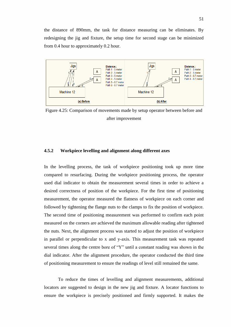
51
the distance of 890mm, the task for distance measuring can be eliminates. By
redesigning the jig and fixture, the setup time for second stage can be minimized
from 0.4 hour to approximately 0.2 hour.
Figure 4.25: Comparison of movements made by setup operator between before and
after improvement
4.5.2 Workpiece levelling and alignment along different axes
In the levelling process, the task of workpiece positioning took up more time
compared to resurfacing. During the workpiece positioning process, the operator
used dial indicator to obtain the measurement several times in order to achieve a
desired correctness of position of the workpiece. For the first time of positioning
measurement, the operator measured the flatness of workpiece on each corner and
followed by tightening the flange nuts to the clamps to fix the position of workpiece.
The second time of positioning measurement was performed to confirm each point
measured on the corners are achieved the maximum allowable reading after tightened
the nuts. Next, the alignment process was started to adjust the position of workpiece
in parallel or perpendicular to x and y-axis. This measurement task was repeated
several times along the centre bore of “Y” until a constant reading was shown in the
dial indicator. After the alignment procedure, the operator conducted the third time
of positioning measurement to ensure the readings of level still remained the same.
To reduce the times of levelling and alignment measurements, additional
locators are suggested to design in the new jig and fixture. A locator functions to
ensure the workpiece is precisely positioned and firmly supported. It makes the
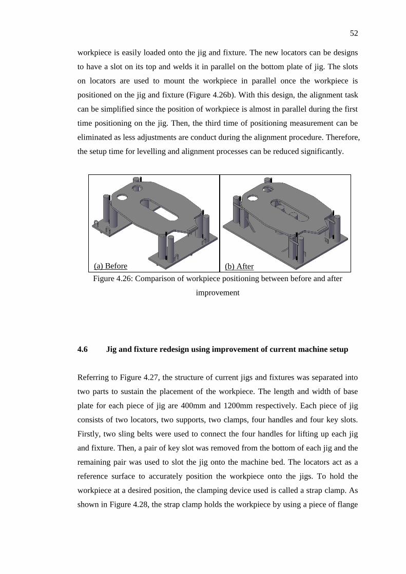
52
workpiece is easily loaded onto the jig and fixture. The new locators can be designs
to have a slot on its top and welds it in parallel on the bottom plate of jig. The slots
on locators are used to mount the workpiece in parallel once the workpiece is
positioned on the jig and fixture (Figure 4.26b). With this design, the alignment task
can be simplified since the position of workpiece is almost in parallel during the first
time positioning on the jig. Then, the third time of positioning measurement can be
eliminated as less adjustments are conduct during the alignment procedure. Therefore,
the setup time for levelling and alignment processes can be reduced significantly.
Figure 4.26: Comparison of workpiece positioning between before and after
improvement
4.6 Jig and fixture redesign using improvement of current machine setup
Referring to Figure 4.27, the structure of current jigs and fixtures was separated into
two parts to sustain the placement of the workpiece. The length and width of base
plate for each piece of jig are 400mm and 1200mm respectively. Each piece of jig
consists of two locators, two supports, two clamps, four handles and four key slots.
Firstly, two sling belts were used to connect the four handles for lifting up each jig
and fixture. Then, a pair of key slot was removed from the bottom of each jig and the
remaining pair was used to slot the jig onto the machine bed. The locators act as a
reference surface to accurately position the workpiece onto the jigs. To hold the
workpiece at a desired position, the clamping device used is called a strap clamp. As
shown in Figure 4.28, the strap clamp holds the workpiece by using a piece of flange
(a) Before (b) After

53
nut and step clamp. One end of step clamp was used to hold the workpiece and the
other end was placed on the support as a fulcrum.
Figure 4.27: Three dimensional view of current jigs and fixtures
Figure 4.28: Clamping method of strap clamp
Based on the analysis in section 4.5, the structure of jig and fixture is
redesigned by eliminating the piece of jig and adding locators onto the jig. In Figure
4.29, it shows that the new jig and fixture is constructed on a piece of base plate. The
length of new base plate is the combination of original length of current jigs plus the
distance of 890mm. Then, the dimensions of new base plate are 1690mm length and
1200mm width. In order to prevent the deformation of jig, the material used to form
the base is a steel plate with thickness of 30mm.
Support
Locator
1200 mm
400 mm
Clamp
Handle
Clamp
Locator
Support
Handle
Flange nut
Key slot

54
Figure 4.29: Three dimensional view of redesigned jig and fixture
In the redesigned jig and fixture, there is no key slot screwed at its bottom of
base plate in order to simplify the jig positioning process. The method of jig
positioning is changed to use clamping parts for holding the base plate onto the
machine table. Referring to Figure 4.30, a T-slot nut is inserted into the slot of
machine table and followed by screwed a stud into the nut. As the jig is positioned
correctly, a step clamp is placed through the stud to hold the jig. One end of clamp is
positioned onto the base plate of jig and the other end with steps is placed on the step
block as a support of clamp. Next, a flange nut is tightened to the stud to restrict the
movement of base plate. The same procedures are repeated three times to clamp the
other edges of base plate.
Figure 4.30: Equipment used for jig positioning (from www.cnccookbook.com)
1690 mm 1200 mm
Clamp
Support
Frame
30mm
steel plate
Locator
Handle
Step block
Machine
table
Base plate
of jig
Step clamp
Flange nut
T-slot nut
Stud
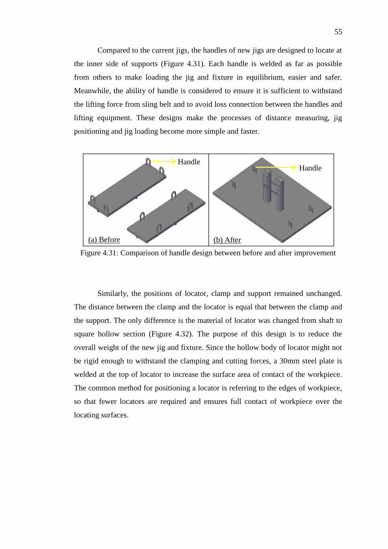
55
Compared to the current jigs, the handles of new jigs are designed to locate at
the inner side of supports (Figure 4.31). Each handle is welded as far as possible
from others to make loading the jig and fixture in equilibrium, easier and safer.
Meanwhile, the ability of handle is considered to ensure it is sufficient to withstand
the lifting force from sling belt and to avoid loss connection between the handles and
lifting equipment. These designs make the processes of distance measuring, jig
positioning and jig loading become more simple and faster.
Figure 4.31: Comparison of handle design between before and after improvement
Similarly, the positions of locator, clamp and support remained unchanged.
The distance between the clamp and the locator is equal that between the clamp and
the support. The only difference is the material of locator was changed from shaft to
square hollow section (Figure 4.32). The purpose of this design is to reduce the
overall weight of the new jig and fixture. Since the hollow body of locator might not
be rigid enough to withstand the clamping and cutting forces, a 30mm steel plate is
welded at the top of locator to increase the surface area of contact of the workpiece.
The common method for positioning a locator is referring to the edges of workpiece,
so that fewer locators are required and ensures full contact of workpiece over the
locating surfaces.
(a) Before (b) After
Handle Handle
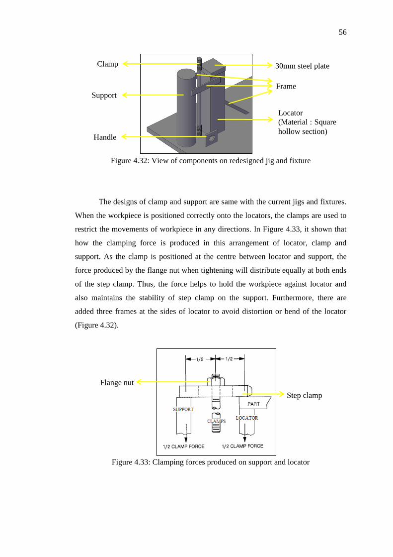
56
Figure 4.32: View of components on redesigned jig and fixture
The designs of clamp and support are same with the current jigs and fixtures.
When the workpiece is positioned correctly onto the locators, the clamps are used to
restrict the movements of workpiece in any directions. In Figure 4.33, it shown that
how the clamping force is produced in this arrangement of locator, clamp and
support. As the clamp is positioned at the centre between locator and support, the
force produced by the flange nut when tightening will distribute equally at both ends
of the step clamp. Thus, the force helps to hold the workpiece against locator and
also maintains the stability of step clamp on the support. Furthermore, there are
added three frames at the sides of locator to avoid distortion or bend of the locator
(Figure 4.32).
Figure 4.33: Clamping forces produced on support and locator
Locator
(Material : Square
hollow section)
30mm steel plate
Frame
Clamp
Support
Handle
Flange nut
Step clamp

57
The last consideration of redesign the jig and fixture is the way to position the
additional locators for reducing the need of levelling and alignment processes. In
some cases, if a workpiece has hole or bore on its surface, the hole or bore provides
the best references to place the locator for positioning the workpiece. Therefore, two
additional locators are designed to position at the centre of jig to hold the centre bore
of the workpiece (Figure 4.34). In order to make the workpiece alignment easier, the
new locators are milled with a slot at its surface to hold the workpiece accurately. It
also acts as a reference line to maintain the workpiece in parallel or perpendicular
position once positioning the workpiece onto the jig. Referring to Figure 4.29, a
frame is welded between the two locators to avoid bending of locator during the
workpiece positioning task.
Figure 4.34: Additional locators on redesigned jig and fixture for ease of alignment
4.7 Validation of jig and fixture redesign
There are five main considerations in validating a jig and fixture design: dimensional
accuracy of structure, ability to support workpiece, safety issues during the operation,
size within specifications of machine table used and the ability to reduce machine
setup time. Workpiece requirements are the major influence on the design of jig and
fixture. It is ensured that the workpiece is fully supported and clamped without
interference of the required machining paths and cutting tools. In Figure 4.35 to 4.37,
the outlines of workpiece and machining paths are combined with the structure of jig
to illustrate all the components would not obstruct the machining operation on the
workpiece.
Workpiece
Locator

58
Figure 4.35: Dimensional validation of jig and fixture (Top view)
Figure 4.36: Dimensional validation of jig and fixture (Front view)
Figure 4.37: Dimensional validation of jig and fixture (Side view)
The ability of base plate, locator, support and clamp is important to withstand
the large clamping force and cutting force. In addition, the basic rule for designing a

59
jig is the base plate must be strong and rigid enough to resist the forces from locators,
clamps, supports and other components. Without these specifications, the parts are
easy to bend and distort and affected the accuracy of jig and fixture. As mentioned in
Chapter 1, there is no analysis for mechanical testing to check the maximum force
and deformation that can be sustained by the components of jig. Since the redesigned
jig follows the standard jig design template in Company “X”, the ability of each
component in redesigned jig and fixture is checked by the experienced supervisor
based on its thickness or diameter.
Safety is another issue to consider when designing the jig and fixture. As the
structure of redesigned jig is constructed on a large base plate, it is heavier than the
current jigs and fixtures. The lifting equipment and sling belts used must be capable
to hold the redesigned jig and sufficient to withstand the weight of redesigned jig.
The lifting capacity of equipment is 3-tons (2721.55 kg) and that of sling belt is 1.5-
tons (1360.78 kg). As the total weight of the redesigned jig is 755 kg, the lifting
equipment and sling belt are able to use for loading the redesigned jig.
Since every model of CNC machine has different sizes of machine table and
T-slot and different value of maximum load on machine table, it is important to
ensure the redesigned jig is able to be use in each single machine. The work table
size of machine operated to produce “Y” is 6000mm length and 2600mm width and
the maximum load on work table is 16,000 kg. As the size of redesigned jig is
1690mm length and 1200mm width and its weight is 755 kg, it is capable to be
positioned onto that machine table.
The last consideration is to examine whether the machine setup time can be
reduced by using the redesigned jig. The main focuses of the redesigned jig are to
simplify the jig loading and positioning processes and eliminate the multiple times of
levelling and alignment processes. Firstly, it combined the two pieces of jigs into one
to make the loading time and distance travelled by operator for jig loading became
shorter. Next, the key slot removing process is eliminated since the method of
redesigned jig positioning is modified by using step clamp and step block to position
the jig onto the machine table. Thirdly, the process for distance measuring between
the jigs is eliminated as the pieces of jig reduced to one. Furthermore, additional

60
locators are welded in parallel at the redesigned jig and fixture to reduce the times of
levelling and alignment measurements. The function of locators is to align the
workpiece in parallel once the workpiece is positioned on the redesigned jig. Then,
the redesign jig and fixture is valid when the three bottleneck processes are
simplified or eliminated.
4.8 Time study of redesigned jig and fixture
Referring to Figure 4.38, the redesigned jig was fabricated through assembly,
welding and CNC machining. Firstly, the bill of material is prepared based on the
design of new jig. The materials are then assembled onto the base plate of jig
according to the dimension listed for each component. After assembly, the welding
process was started by welding the base plate and other components to fix its desired
position. As each component is cut by thermal process, the surface of each
component is uneven. The purpose of CNC machining onto the redesigned jig is to
ensure each locators and support has the same level of flatness to position the
workpiece.
Figure 4.38: Real view of redesigned jig and fixture
By using the redesigned jig and fixture, a time motion study was conducted to
determine the degree of improvement of machine setup time. Similarly, each setup
task and its exact time required are listed in the monitoring paper (Table 4.4).
Comparing all the data collected before and after improvement, there is only small a
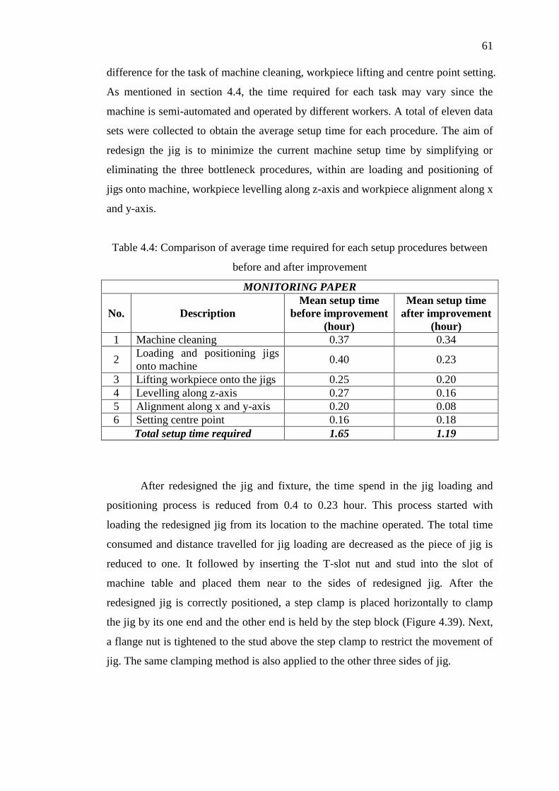
61
difference for the task of machine cleaning, workpiece lifting and centre point setting.
As mentioned in section 4.4, the time required for each task may vary since the
machine is semi-automated and operated by different workers. A total of eleven data
sets were collected to obtain the average setup time for each procedure. The aim of
redesign the jig is to minimize the current machine setup time by simplifying or
eliminating the three bottleneck procedures, within are loading and positioning of
jigs onto machine, workpiece levelling along z-axis and workpiece alignment along x
and y-axis.
Table 4.4: Comparison of average time required for each setup procedures between
before and after improvement
MONITORING PAPER
No. Description
Mean setup time
before improvement
(hour)
Mean setup time
after improvement
(hour)
1 Machine cleaning 0.37 0.34
2 Loading and positioning jigs
onto machine 0.40 0.23
3 Lifting workpiece onto the jigs 0.25 0.20
4 Levelling along z-axis 0.27 0.16
5 Alignment along x and y-axis 0.20 0.08
6 Setting centre point 0.16 0.18
Total setup time required 1.65 1.19
After redesigned the jig and fixture, the time spend in the jig loading and
positioning process is reduced from 0.4 to 0.23 hour. This process started with
loading the redesigned jig from its location to the machine operated. The total time
consumed and distance travelled for jig loading are decreased as the piece of jig is
reduced to one. It followed by inserting the T-slot nut and stud into the slot of
machine table and placed them near to the sides of redesigned jig. After the
redesigned jig is correctly positioned, a step clamp is placed horizontally to clamp
the jig by its one end and the other end is held by the step block (Figure 4.39). Next,
a flange nut is tightened to the stud above the step clamp to restrict the movement of
jig. The same clamping method is also applied to the other three sides of jig.

62
Figure 4.39: Redesigned jig clamping onto the machine table
Similarly, the levelling procedure is divided into two parts: workpiece
positioning and resurfacing. After the workpiece is positioned onto the redesigned jig,
a reference point is pointed in anywhere of bottom plate of workpiece. The operator
started the first positioning measurement to measure the flatness of workpiece on
each corner. Then, the flange nuts are tightened again to the clamps until achieved
the maximum allowable reading but not screwed fully to allow adjustment during the
next procedure. It followed by conducting the second time of positioning
measurement to ensure all points measured are reached the maximum allowable
reading after tightened the nuts. The same procedure of resurfacing task is performed
after confirmed that all points measured are in the same level along the z-axis.
Compared to the current jigs and fixtures, the redesigned jig eliminates the third time
of positioning measurement as new locators are added to minimize the adjustment
actions during the alignment procedure. Therefore, the setup time for levelling
process is decreased from 0.27 to 0.16 hour after improvement.
The next improvement is the time of alignment measurement is reduced. The
new locators are designed to have a slot on its top surface and welded in parallel on
the base plate of jig. It acts as a reference surface to make the workpiece easily
positioned in parallel to machine table’s axes. Thus, less adjustments and alignment
measurements are conducted to obtain a constant reading on dial indicator. The setup
time for this process is minimized from 0.2 to 0.08 hour.
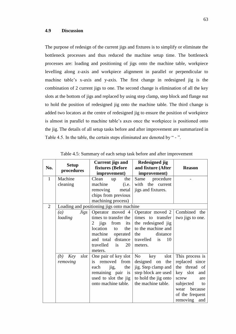
63
4.9 Discussion
The purpose of redesign of the current jigs and fixtures is to simplify or eliminate the
bottleneck processes and thus reduced the machine setup time. The bottleneck
processes are: loading and positioning of jigs onto the machine table, workpiece
levelling along z-axis and workpiece alignment in parallel or perpendicular to
machine table’s x-axis and y-axis. The first change in redesigned jig is the
combination of 2 current jigs to one. The second change is elimination of all the key
slots at the bottom of jigs and replaced by using step clamp, step block and flange nut
to hold the position of redesigned jig onto the machine table. The third change is
added two locators at the centre of redesigned jig to ensure the position of workpiece
is almost in parallel to machine table’s axes once the workpiece is positioned onto
the jig. The details of all setup tasks before and after improvement are summarized in
Table 4.5. In the table, the certain steps eliminated are denoted by “ - ”.
Table 4.5: Summary of each setup task before and after improvement
No. Setup
procedures
Current jigs and
fixtures (Before
improvement)
Redesigned jig
and fixture (After
improvement)
Reason
1 Machine
cleaning
Clean up the
machine (i.e.
removing metal
chips from previous
machining process)
Same procedure
with the current
jigs and fixtures.
-
2 Loading and positioning jigs onto machine
(a) Jigs
loading
Operator moved 4
times to transfer the
2 jigs from its
location to the
machine operated
and total distance
travelled is 20
meters.
Operator moved 2
times to transfer
the redesigned jig
to the machine and
the distance
travelled is 10
meters.
Combined the
two jigs to one.
(b) Key slot
removing
One pair of key slot
is removed from
each jig, the
remaining pair is
used to slot the jig
onto machine table.
No key slot
designed on the
jig. Step clamp and
step block are used
to hold the jig onto
the machine table.
This process is
replaced since
the thread of
key slot and
screw are
subjected to
wear because
of the frequent
removing and

64
tightening of
the screw to
the key slot.
(c) Distance
measuring
Operator measured
and adjusted the
jigs in a distance of
890mm to position
the workpiece
correctly onto it.
- This process is
eliminated
since the new
jig is designed
to have the
length of
original jigs
plus the
distance of
890mm.
3 Lifting
workpiece onto
the jigs
Workpiece is
loaded from its
original place onto
the machine. Flange
nuts were tightened
to the clamps to fix
the position of
workpiece.
Same procedure
with the current
jigs and fixtures.
Pay more attention
when positioning
the workpiece to
avoid impact on
the components of
jig.
Additional
locators are
welded at the
centre of
redesigned jig
to hold the
centre bore of
the workpiece.
4 Levelling along z-axis
(a) 1st
positioning
measurement
Operator measured
the flatness of
workpiece on each
corner and followed
by tightening the
flange nuts to the
clamps.
Same procedure
with the current
jigs and fixtures.
-
(b) 2nd
positioning
measurement
Performed to
confirm each point
measured on the
corners is achieved
the maximum
allowable reading
after tightened the
nuts.
Same procedure
with the current
jigs and fixtures.
-
(c) Resurfacing 3 points measured
to decide the depth
of cut for milling
the circular slot.
Same procedure
with the current
jigs and fixtures.
-
(d) 3rd
positioning
measurement
To ensure the
readings of level
still remained the
same after the
alignment
procedure.
- Less
adjustments
are conducted
during the
alignment
procedure.
5 Alignment
along x and y-
Repeated several
times along the
The times of
alignment is
Additional
locators are

65
0.46
1.65
axis centre bore of
workpiece to adjust
the position of
workpiece in
parallel or
perpendicular to x
and y-axis.
reduced. designed to
align the
workpiece
almost in
parallel during
the first time
positioning on
the jig.
6 Setting centre
point
Edge finder is used
to determine the
edges of the bore
along x and y-axis
and thus the centre
of workpiece can be
easily located.
Same procedure
with the current
jigs and fixtures.
-
Referring to section 4.8, the improved machine setup time is 1.19 hours and
thus the total setup time reduced is 0.46 hour. By applying simple calculation, the
percentage of setup time reduction is 27.88% after using the redesigned jig in Step 1
of “Y” production. This calculated percentage proved that the target setup time
reduction in section 4.3 is achieved. In Table 4.6, the details of quality inspections
after Step 1 machining for product “Y” by using current and redesigned jigs are
recorded. It showed that the quality of workpiece is maintained after the
improvement.
Total machine setup time reduced = 1.65 – 1.19
= 0.46 hour
Percentage of setup time reduction = X 100%
= 27.88%
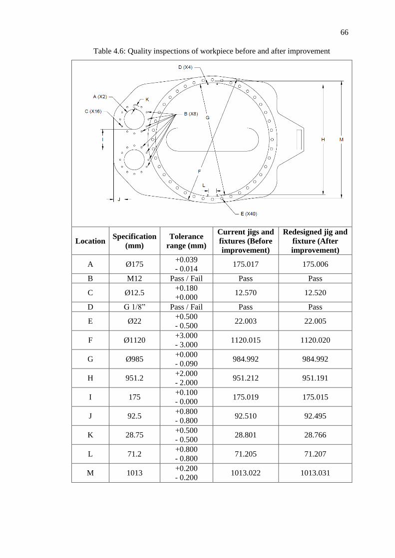
66
Table 4.6: Quality inspections of workpiece before and after improvement
Location Specification
(mm)
Tolerance
range (mm)
Current jigs and
fixtures (Before
improvement)
Redesigned jig and
fixture (After
improvement)
A Ø175 +0.039
- 0.014 175.017 175.006
B M12 Pass / Fail Pass Pass
C Ø12.5 +0.180
+0.000 12.570 12.520
D G 1/8” Pass / Fail Pass Pass
E Ø22 +0.500
- 0.500 22.003 22.005
F Ø1120 +3.000
- 3.000 1120.015 1120.020
G Ø985 +0.000
- 0.090 984.992 984.992
H 951.2 +2.000
- 2.000 951.212 951.191
I 175 +0.100
- 0.000 175.019 175.015
J 92.5 +0.800
- 0.800 92.510 92.495
K 28.75 +0.500
- 0.500 28.801 28.766
L 71.2 +0.800
- 0.800 71.205 71.207
M 1013 +0.200
- 0.200 1013.022 1013.031
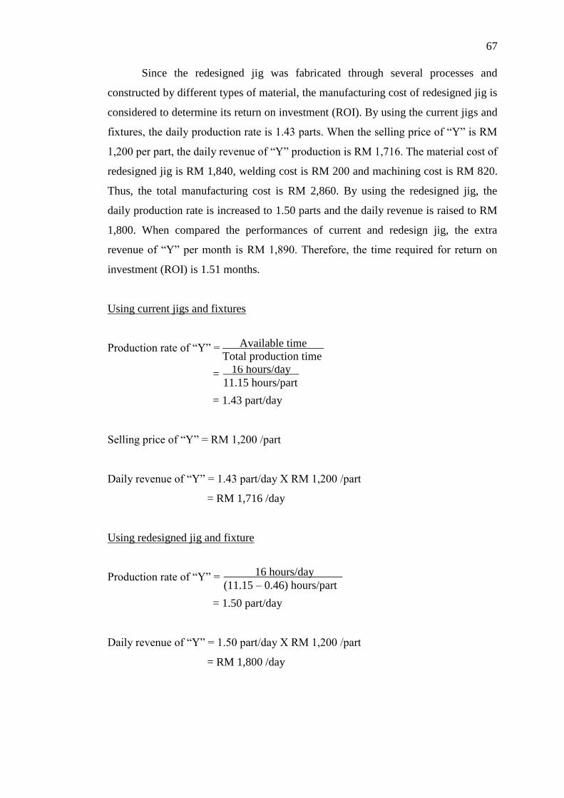
67
16 hours/day l
11.15 hours/part
Available time l
Total production time
16 hours/day l
(11.15 – 0.46) hours/part
Since the redesigned jig was fabricated through several processes and
constructed by different types of material, the manufacturing cost of redesigned jig is
considered to determine its return on investment (ROI). By using the current jigs and
fixtures, the daily production rate is 1.43 parts. When the selling price of “Y” is RM
1,200 per part, the daily revenue of “Y” production is RM 1,716. The material cost of
redesigned jig is RM 1,840, welding cost is RM 200 and machining cost is RM 820.
Thus, the total manufacturing cost is RM 2,860. By using the redesigned jig, the
daily production rate is increased to 1.50 parts and the daily revenue is raised to RM
1,800. When compared the performances of current and redesign jig, the extra
revenue of “Y” per month is RM 1,890. Therefore, the time required for return on
investment (ROI) is 1.51 months.
Using current jigs and fixtures
Production rate of “Y” =
=
= 1.43 part/day
Selling price of “Y” = RM 1,200 /part
Daily revenue of “Y” = 1.43 part/day X RM 1,200 /part
= RM 1,716 /day
Using redesigned jig and fixture
Production rate of “Y” =
= 1.50 part/day
Daily revenue of “Y” = 1.50 part/day X RM 1,200 /part
= RM 1,800 /day
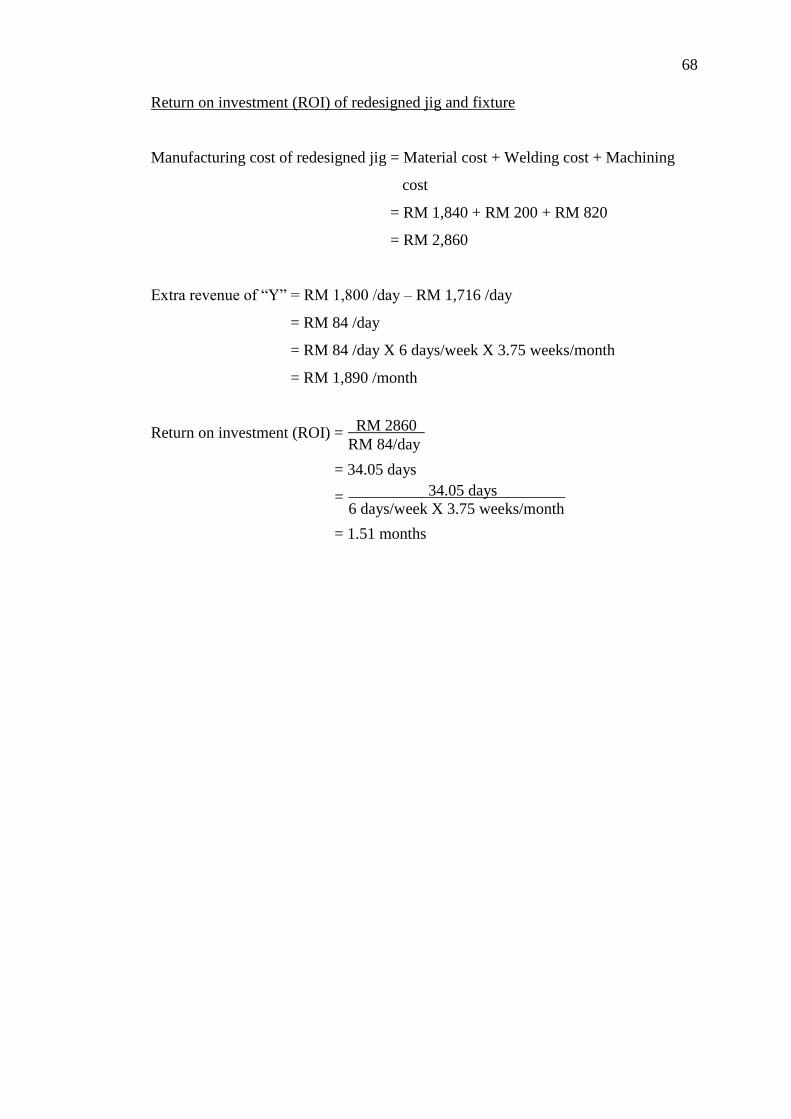
68
RM 2860 l
RM 84/day
34.05 days l
6 days/week X 3.75 weeks/month
Return on investment (ROI) of redesigned jig and fixture
Manufacturing cost of redesigned jig = Material cost + Welding cost + Machining
cost
= RM 1,840 + RM 200 + RM 820
= RM 2,860
Extra revenue of “Y” = RM 1,800 /day – RM 1,716 /day
= RM 84 /day
= RM 84 /day X 6 days/week X 3.75 weeks/month
= RM 1,890 /month
Return on investment (ROI) =
= 34.05 days
=
= 1.51 months

69
CHAPTER 5
5 CONCLUSION AND RECOMMENDATIONS
In a modern manufacturing environment, organizations must be responsive to the
requirements of the customers and their specific needs and to fluctuating global
market demands. To maintain its competitiveness in market share, the manufacturing
firms must be conducted with a minimum amount of wasted resources. The main
focus of this research is to reduce the setup time for the first machining step of a high
demand product, “Y”. The proposed solution is redesigns the current jigs and fixtures
to simplify the setup procedures.
The objectives of this thesis are determines the underlying problems in the
current jigs and fixtures and propose new jig design in order to overcome the
problems listed. With the assistance of current jigs, there are six setup procedures in
Step 1 and three out of six procedures are considered as bottleneck processes. The
first bottleneck process is jig loading and positioning onto the machine table. This
task is the highest setup time consumed in Step 1. The operator loaded up the 2 jigs
to remove a pair of key slots and then transferred the jigs onto the machine bed.
When the jigs are ready on the machine, the operator measured and adjusted the jigs
in a distance of 890mm to support the workpiece. The second bottleneck process is
workpiece levelling along the z-axis. This stage involved minimum three times of
positioning measurements to ensure the workpiece is precisely positioned. The third
bottleneck process is workpiece alignment along the x and y-axis. This measurement
task is repeated several times until the position of workpiece is in parallel or
perpendicular to x and y-axis.

70
In order to solve these problems, the new jig is designed to combine the two
current jigs to one. It reduces the number of paths moved by operator and makes the
distance travelled for jig loading became shorter. With a piece of jig and fixture, the
distance measuring task is eliminated. The key slot removing task is also eliminated
and the method of jig positioning is replaced by using step clamp, step block and
flange nut to hold it at a desired position onto the machine table. Besides, two
additional locators are designed to weld in parallel at the centre of redesigned jig to
reduce the several times of levelling and alignment measurements. With the new
locators, the position of workpiece is almost in parallel once it positioned onto the
redesigned jig. Thus, less alignment measurements and adjustments are performed to
correct the position of workpiece. Then, the third time of positioning measurement is
eliminated as less adjustments are conduct during the alignment procedure.
By using the redesigned jig and fixture, the machine setup time is reduced
from 1.65 to 1.19 hours. The percentage of setup time reduction is 27.88% which
achieved the target setup time reduction. Furthermore, the daily production rate of
“Y” is improved from 1.43 to 1.50 parts and the daily revenue is increased from RM
1,716 to RM 1,800. Then, the extra revenue of “Y” is RM 84 per day. As the total
manufacturing cost of redesigned jig is RM 2,860, the time required for return on
investment (ROI) is 1.51 months.
There are few recommendations for conducting future research. In order to
achieve a higher daily production rate of “Y”, the total setup time per part can be
further reduces by applying the same methodology to study the setup processes in
Step 2 and 3. Referring to section 4.2, the setup time for Step 2 was 1.22 hours and
1.03 hours for Step 3. In Step 2, the bottleneck procedure was loading and adjusting
the two pieces of jigs in a certain distance. For Step 3, the longest setup time
procedure was workpiece positioning to clamp the workpiece in position onto the jig.
Therefore, the suggested method is to redesign the jigs and fixtures of these steps to
minimize its setup time.
The second recommendation is to study the effect of different improvement
method such as increasing the number of operators to assist in the process of
machine cleaning, jig clamping and workpiece positioning. In the current setup

71
process, the average time that is consumed in the machine cleaning task was 0.37
hour which is the second setup bottleneck. Generally, with more operators to clean
the machine operated, this task can be conducted faster. In the jig clamping and
workpiece positioning processes, the flange nuts were tightened to the clamps to hold
the parts at a desired position. When more operators assist in the clamping work,
these processes can be completed in shorter time.
The third recommendation is investigates the outcome of combination of jig
redesign and different setup tool. In Chapter 2, four setup tools are researched to
reduce machine setup time, those are Kaizen, JIT, SMED, and jig and fixture design.
When combining Kaizen and jig redesign, the management can apply 5S technique
as a Kaizen tool to sort the required tools in order for further reducing the machine
setup time. By using JIT and jig redesign, the machine setup time can be further
reduced as it eliminates many wastes such as the waste of motion from workstation
to storage area. With SMED and jig redesign, the streamlining stage of SMED can be
applied to eliminate, simplify and reduce any step which is considered unnecessary.

72
REFERENCES
Adam, M., Componation, P., Czarnecki, H. and Schroer, B.J., 2014. Simulation as a
tool for continuous process improvement. Simulation Conference Proceedings, 1,
pp. 766-773.
Adanna, I.W. and Shantharam, A., 2013. Improvement of setup time and production
output with the use of single minute exchange of die principles (SMED).
International Journal of Engineering Research, 2(4), pp.274-277.
Ahmed, S., Hassan, M.H. and Yap, H.F., 2005. Performance measurement and
evaluation in an innovative modern manufacturing system. Journal of Applied
Sciences, 5(2), pp.385-401.
Brunet, A.P. and New, S., 2003. Kaizen in Japan: An empirical study. International
Journal of Operations and Production Management, 23(12), pp. 1426-1446.
Burns, A., 2000. Choosing the right tool from the tool box: Some examples of gemba
Kaizen practice. UK: IEE Seminar, 6, pp. 1-10.
Che Ani, M.N. and Shafei, M.S.S., 2015. The effectiveness of the single minute
exchange of die (SMED) technique for the productivity improvement. Applied
Mechanics and Materials, 465-466, pp.1144-1148.
Cua, K.O., McKone, K.E. and Schroeder, R.G., 2001. Relationships between
implementation of TQM, JIT, and TPM and manufacturing performance. Journal
of Operations Management, 19(6), pp. 675-694.
Dagalakis, N.G., Kang, B.H., Wen, T.Y. and Gorman, J.J., 2005. Analysis and
design of parallel mechanisms with flexure joints. IEEE Transactions on Robotics,
21(6), pp1179-1185.
Daniel, P.H. and Kelly, J.F., 2009. Build your own CNC machine. [ebook] United
States: Paul Manning. Available at: Google Books<books.google.com> [Accessed
27 Jan. 2016].
Davim, J.P., 2001. A note on the determination of optimal cutting conditions for
surface finish obtained in turning using design of experiments. Journal of
Materials Processing Technology, 116(2-3), pp. 305-308.

73
Dehghan, R/, Zohrab, M., Momeni, A. and Hoseini, M., 2006. Continuous
improvement approach in the agriculture sector. Asian Pacific Productivity
Conference, Seoul National University, South Korea.
Deng, H. and Melkote, S.N., 2006. Determination of minimum clamping forces for
dynamically stable fixturing. International Journal of Machine Tools and
Manufacture, 46(7-8), pp. 847-857.
Diaz, M.S., Machuca, J.A.D. and Alvarez-Gil, M.J., 2003. A view of developing
patterns of investment in AMT through empirical taxonomies: New evidence.
Journal of Operations Management, 21(5), pp. 577-606.
Doolen, T.L. and Hacker, M.E., 2005. A review of lean assessment in organizations:
An exploratory study of lean practices by electronics manufacturers. Journal of
Manufacturing Systems, 24(1), pp.55-67.
Dowlatshahi, S. and Taham, F., 2009. The development of a conceptual framework
for Just-In-Time implementation in SMEs. Production Planning and Control,
20(7), pp. 611-621.
Fallah, M. and Arezoo, B., 2013. Modelling and compensation of fixture locators’
error in CNC milling. International Journal of Production Research, 51(15), pp.
4539-4555.
Farris, J.A., Aken, E.M.V., Doolen, T.L. and Worley, J., 2008. Learning from less
successful Kaizen events: A case study. Engineering Management Journal, 20(3),
pp. 10-20.
Fullerton, R.R., McWatters, C.S. and Fawson, C., 2002. An examination of the
relationships between JIT and financial performance. Journal of Operations
Management, 21(4), pp.383-404.
Gordon, J. and Sohal, A.S., 2001. Assessing manufacturing plant competitiveness:
An empirical field study. International Journal of Operations and Production
Management, 21(1-2), pp. 233-253.
Hunter, R., Rios, J., Perez, J.M. and Vizan, A., 2005. A functional approach for the
formalization of the fixture design process. International Journal of Machine Tool
and Manufacture, 46(6), pp. 683-697.
Jagdeep, S. and Harwinder, S., 2009. Kaizen philosophy: A review of literature. The
Icfai University Journal of Operations Management, 3(2), pp.51-72.
Jayendran, A., 2006. Mechanical engineering. [ebook] Germany: B. G. Teubner
Verlag. Available at: Google Books<books.google.com> [Accessed 20 Jan. 2016].

74
Joneja, A. and Chang, T.C., 2010. Setup and fixture planning in automated process
planning systems. IIE Transactions, 31, pp. 653-665.
Joshi, P., 2010. Jigs and fixtures. [ebook] India: Tata McGraw Hill Education Private.
Available at: Google Books<books.google.com> [Accessed 2 Mar. 2016].
Kaija, T. and Heino, P., 2006. The optimization of on-wafer shield-based test fixture
layout. IEEE Transactions: Microwave Theory and Techniques, 54(5), pp. 1975-
1982.
Kais, B. and Kara, S., 2007. Set up reduction in injection molding process: A case
study in packaging industry, pp. 21-23.
Kakish, J., Zhang, P.L. and Zeid, I., 2000. Toward the design and development of a
knowledge-based universal modular jigs and fixtures system. Journal of
Intelligent Manufacturing, 11, pp.381-401.
Kang, S.K., Suh, S.H., Chung, D.H. and Stroud, T., 2008. Theory and design of CNC
systems. [ebook] London: Springer-Verlag. Available at: Google
Books<books.google.com> [Accessed 23 Feb. 2016].
Kaya, N., 2006. Machining fixture locating and clamping position optimization using
genetic algorithms. Computers in Industry, 57, pp. 112-120.
Koc, T. and Bozdag, E., 2006. An empirical research for CNC technology
implementation in manufacturing SMEs. International Journal of Advanced
Manufacturing Technology, 34(11), pp.1144-1152.
Koskela, L., Bolviken, T. and Rooke, J., 2013. Which are the wastes of construction.
Annual Conference of the International Group for Lean Construction, Brazil.
Kumar, P.C., 2012. Set up reduction: A perfect way for productivity improvement of
computer numerical control (CNC) set up in manufacturing company. Journal of
Mechanical Engineering Research, 5(8), pp.166-170.
Kusar, J., Berlec, T., Zefran, F. and Starbek, M., 2010. Reduction of machine setup
time. Journal of Mechanical Engineering, 56(12), pp.833-845.
Lagace, D. and Bourgault, M., 2003. Linking manufacturing improvement programs
to the competitive priorities of Canadian SMEs. Technovation, 23(8), pp. 705-715.
Landry, S.P., 2008. Do modern Japanese inventory methods apply to Hong Kong.
International Business and Economics Research Journal, 7(4), pp. 21-36.
Lee, M., 2000. Customer service excellence through people motivation and Kaizen.
IEE Seminar, 5, pp. 1-21.

75
Levary, R.R., 2007. Just-in-time manufacturing. European Journal of Engineering
Education, 17(3), pp.307-311.
Liqing, F. and Kumar, A.S., 2005. XML – based representation in a CBR system for
fixture design. Computer Aided Design and Application, 2(1-4), pp. 339-348.
Marin, R.A. and Ferreira, P.M., 2003. Analysis of the influence of fixture locator
errors on the compliance of work part features to geometric tolerance
specifications. Journal of Manufacturing Science and Engineering, 125(3), pp.
609-616.
Moreira, A.C. and Pais, G.C.S., 2011. Single minute exchange of dies: A case study
implementation. Journal of Technology Management and Innovation, 6(1),
pp.129-146.
Nalbandh, A.H. and Rajyaguru, C.C., 2012. Fixture design optimization using
genetic algorithm: A review. Journal of Information, Knowledge and Research in
Mechanical Engineering, 2(2), pp.466-471.
Nanthakumar, K. and Prabakaran, V., 2014. Design and fabrication testing of
combined multipurpose jig and fixture. Journal of Mechanical and Civil
Engineering, 11(4), pp. 86-91.
Newman, S.T., Nassehi, A., Xu, X.W., Wang, L., Yusof, Y., Ali, L., Liu, R., Zheng,
L.Y., Kumar, S., Vichare, P. and Dhokia, V., 2008. Strategic advantages of
interoperability for global manufacturing using CNC technology. Robotics and
Computer-Integrated Manufacturing, 24(6), pp.699-708.
Okpala, C.C. and Okechukwu, E., 2015. The design and need for jigs and fixtures in
manufacturing. Science Research, 3(4), pp. 213-219.
Pallegrini, S., Shetty, D. and Manzione, L., 2012. Study and implementation of
single minute exchange of die (SMED) methodology in a setup reduction Kaizen.
International Conference on Industrial Engineering and Operations Management,
pp.2353-2363.
Pattantyus, A., 2013. Lean empowerment – Setup time reduction. Retrieved February
24, 2016, from http://strategicmodularity.com/2013/08/lean-empowerment-part-2-
setup-time-reduction/
Pecas, P. and Henriques, E., 2006. Best practices of collaboration between university
and industrial SMEs. Benchmarking: An International Journal, 13(1-2), pp. 54-67.
Poppendieck, M., 2002. Principles of lean thinking. USA.

76
Qin, G.H., Zhang, W.H. and Wan, M., 2006. A mathematical approach to analysis
and optimal design of a fixture locating scheme. The International Journal of
Advanced Manufacturing Technology, 29, pp. 349-359.
Raghu, A. and Melkote, S.N., 2004. Analysis of the effects of fixture clamping
sequence on part location errors. International Journal of Machine Tools and
Manufacture, 44(4), pp. 373-382.
Rajenthirakumar, D. and Thyla, P.R., 2011. Transformation to lean manufacturing by
an automative component manufacturing company. International Journal of Lean
Thinking, 2(2).
Rini, D.P., Shamsuddin, S.M. and Yuhaniz, S.S., 2011. Particle swarm optimization:
Technique, system and challenges. International Journal of Computer
Applications, 14(1), pp.19-27.
Shah, R. and Ward, P.T., 2003. Lean manufacturing: Context, practice bundles and
performance. Journal of Operations Management, 21(2), pp. 129-149.
Shin, S.J., Suh, S.H. and Stroud, I., 2007. Reincarnation of G-code based part
programs into STEP-NC for turning applications. Computer-Aided Design, 39(1),
pp. 1-16.
Smid, P., 2010. CNC control setup for milling and turning. [ebook] Available at:
Google Books<books.google.com> [Accessed 15 Feb. 2016].
Stadnicka, D., 2014. Setup analysis: Combining SMED with other tools.
Management and Production Engineering Review, 6(1), pp. 36-50.
Suh, N.P., 2001. Axiomatic design: Advances and applications. Oxford University
Press, Oxford.
Sun, H., Tian, Y. and Cui, H., 2001. Evaluating advanced manufacturing technology
in Chinese state-owned enterprises: A survey and case studies. International
Journal of Advanced Manufacturing Technology, 18(7), pp. 528-536.
Sundar, R., Balaji, A.N. and Kumar, R.M.S., 2014. A review on lean manufacturing
implementation techniques. Procedia Engineering, 97, pp. 1875-1885.
Tian, S., Huang, Z., Chen, L. and Wang Q., 2006. A feature-based approach for
optimal workpiece localization and determination of feasible clamping regions.
The International Journal of Advanced Manufacturing Technology, 30, pp. 76-86.
Timansani, R., Mahesh, N.S. and Doss K., 2011. Reducing the setup time in a CNC
machining line using QCO methods. SASTech – Technical Journal, 10(2), pp. 56-
61.
77
Upadhye, N., Deshmukh, S.G. and Garg, S., 2010. Lean manufacturing system for
medium size manufacturing enterprises: An indian case. International Journal of
Management Science and Engineering Management, 5(5), pp. 362-375.
Venkatesh, S., Odendahi, D., Xu, X., Michaloski, J., Proctor, F. and Kramer, T.
Validating portability of STEP-NC tool center programming. Computers and
Information in Engineering Conference, 3(25), pp. 285-290.
Vichare, P., Kumar, S., Newman, S.T., Nassehi, A. and Tiwari M.K., 2010. An
information model for process control on machine tools. Advances in Intelligent
and Soft Computing, 66, pp. 1565-1582.
Ward, P.T. and Duray, R., 2000. Manufacturing strategy in context: Environment,
competitive strategy and manufacturing strategy. Journal of Operations
Management, 18(2), pp. 123-138.
Yavuz, M. and Akcali,E., 2007. Production smoothing in just-in-time manufacturing
systems: A review of the models and solution approaches. International Journal
of Production Research, 45(16), pp.3579-3597.
Zahid, M.N.O., Case, K. and Watts, D., 2015. End mill tools integration in CNC
machining for rapid manufacturing processes: Simulation studies. Production and
Manufacturing Research, 3(1), pp. 274-288.
Zhang, Q.Y., Vonderembse, M.A. and Lim, J.S., 2003. Manufacturing flexibility:
Defining and analyzing relationships among competence, capability, and customer
satisfaction. Journal of Operations Management, 21(2), pp.173-191.
Zhou, Y., Li, Y. and Wang, W., 2011. A feature-based fixture design methodology
for the manufacturing of aircraft structural parts. Robotics and Computer-
Integrated Manufacturing, 27(6), pp. 986-993.

78


