
Setup, Operation & Maintenance Manual - Dorner …...2100 Series End Drive Conveyors Setup,...
24
851-061 Rev. G Setup, Operation & Maintenance Manual 2100 Series End Drive Conveyors Table of Contents Warnings – General Safety 2 . . . . . . . . . . . . . . . . . . . . . . . . . . . Introduction 2 . . . . . . . . . . . . . . . . . . . . . . . . . . . . . . . . . . . . . . . . Installation General Instructions for All Conveyors 4 . . . . . . . . . . . . Flat Belt Mounting Brackets 5 . . . . . . . . . . . . . . . . . . . . . Cleated Belt Mounting Brackets 6 . . . . . . . . . . . . . . . . . . Start-up & Preliminary Belt Tracking Check 7 . . . . . . . . Maintenance Lubrication 8 . . . . . . . . . . . . . . . . . . . . . . . . . . . . . . . . . . Pulley Bearings 8 . . . . . . . . . . . . . . . . . . . . . . . . . . . . . . . Top or Bottom Mounting Package 8 . . . . . . . . . . . . . . Standard Load Flat Belt Side Mounting Package 9 . . . Standard Load Cleated Belt Side Mounting Package 9 Light Load Side Mounting Package 9 . . . . . . . . . . . . . Conveyor Belts 10 . . . . . . . . . . . . . . . . . . . . . . . . . . . . . . Component Replacement & Adjustments Conveyor Repair Preparations 11 . . . . . . . . . . . . . . . . . . . Tools 11 . . . . . . . . . . . . . . . . . . . . . . . . . . . . . . . . . . . . Checklist 11 . . . . . . . . . . . . . . . . . . . . . . . . . . . . . . . . . Conveyor Belt Replacement Procedure 11 . . . . . . . . . . . . Belt Removal for Conveyor Only (No Stands or Gearmotor Mounting Package) 11 . . . . Belt Removal for End Drive Conveyors with Gearmotors and/or Support Stands 11 . . . . . . . . . . . . . Belt Replacement for All End Drive Conveyors 12 . . . Conveyor Belt Tension for End Drive Conveyors 13 . . . . Conveyor Belt Tracking Adjustment 14 . . . . . . . . . . . . . . Outboard Drive Shaft Replacement 14 . . . . . . . . . . . . . . . Removal 14 . . . . . . . . . . . . . . . . . . . . . . . . . . . . . . . . . Installation 15 . . . . . . . . . . . . . . . . . . . . . . . . . . . . . . . . Pulley Removal Procedure 16 . . . . . . . . . . . . . . . . . . . . . Pulley Bearing Replacement 16 . . . . . . . . . . . . . . . . . . . . Removal 16 . . . . . . . . . . . . . . . . . . . . . . . . . . . . . . . . . Installation 17 . . . . . . . . . . . . . . . . . . . . . . . . . . . . . . . . Pulley Replacement Procedure 17 . . . . . . . . . . . . . . . . . . Timing Belt Tension Adjustment 18 . . . . . . . . . . . . . . . . . Troubleshooting Guide Bearings 19 . . . . . . . . . . . . . . . . . . . . . . . . . . . . . . . . . . . . Gearmotors 19 . . . . . . . . . . . . . . . . . . . . . . . . . . . . . . . . . Conveyor Belt 19 . . . . . . . . . . . . . . . . . . . . . . . . . . . . . . . Timing Belt 20 . . . . . . . . . . . . . . . . . . . . . . . . . . . . . . . . . Replacement Parts Conveyor Belt Part Number 21 . . . . . . . . . . . . . . . . . . . . Drive / Idler Pulleys 22 . . . . . . . . . . . . . . . . . . . . . . . . . . . Hex to Round Adapter Assembly 22 . . . . . . . . . . . . . . . . Flat Belt Return Rollers 23 . . . . . . . . . . . . . . . . . . . . . . . Cleated Belt Return Rollers 23 . . . . . . . . . . . . . . . . . . . .
Transcript of Setup, Operation & Maintenance Manual - Dorner …...2100 Series End Drive Conveyors Setup,...

851-061 Rev. G
Setup, Operation& Maintenance Manual
2100 Series End Drive Conveyors
Table of Contents
Warnings – General Safety 2. . . . . . . . . . . . . . . . . . . . . . . . . . . Introduction 2. . . . . . . . . . . . . . . . . . . . . . . . . . . . . . . . . . . . . . . . Installation
General Instructions for All Conveyors 4. . . . . . . . . . . .
Flat Belt Mounting Brackets 5. . . . . . . . . . . . . . . . . . . . .
Cleated Belt Mounting Brackets 6. . . . . . . . . . . . . . . . . .
Start-up & Preliminary Belt Tracking Check 7. . . . . . . . Maintenance
Lubrication 8. . . . . . . . . . . . . . . . . . . . . . . . . . . . . . . . . .
Pulley Bearings 8. . . . . . . . . . . . . . . . . . . . . . . . . . . . . . .
Top or Bottom Mounting Package 8. . . . . . . . . . . . . .
Standard Load Flat Belt Side Mounting Package 9. . .
Standard Load Cleated Belt Side Mounting Package 9
Light Load Side Mounting Package 9. . . . . . . . . . . . .
Conveyor Belts 10. . . . . . . . . . . . . . . . . . . . . . . . . . . . . . Component Replacement & Adjustments
Conveyor Repair Preparations 11. . . . . . . . . . . . . . . . . . .
Tools 11. . . . . . . . . . . . . . . . . . . . . . . . . . . . . . . . . . . .
Checklist 11. . . . . . . . . . . . . . . . . . . . . . . . . . . . . . . . .
Conveyor Belt Replacement Procedure 11. . . . . . . . . . . . Belt Removal for Conveyor Only(No Stands or Gearmotor Mounting Package) 11. . . .
Belt Removal for End Drive Conveyors withGearmotors and/or Support Stands 11. . . . . . . . . . . . .
Belt Replacement for All End Drive Conveyors 12. . .
Conveyor Belt Tension for End Drive Conveyors 13. . . .
Conveyor Belt Tracking Adjustment 14. . . . . . . . . . . . . .
Outboard Drive Shaft Replacement 14. . . . . . . . . . . . . . .
Removal 14. . . . . . . . . . . . . . . . . . . . . . . . . . . . . . . . .
Installation 15. . . . . . . . . . . . . . . . . . . . . . . . . . . . . . . .
Pulley Removal Procedure 16. . . . . . . . . . . . . . . . . . . . .
Pulley Bearing Replacement 16. . . . . . . . . . . . . . . . . . . .
Removal 16. . . . . . . . . . . . . . . . . . . . . . . . . . . . . . . . .
Installation 17. . . . . . . . . . . . . . . . . . . . . . . . . . . . . . . .
Pulley Replacement Procedure 17. . . . . . . . . . . . . . . . . .
Timing Belt Tension Adjustment 18. . . . . . . . . . . . . . . . . Troubleshooting Guide
Bearings 19. . . . . . . . . . . . . . . . . . . . . . . . . . . . . . . . . . . .
Gearmotors 19. . . . . . . . . . . . . . . . . . . . . . . . . . . . . . . . .
Conveyor Belt 19. . . . . . . . . . . . . . . . . . . . . . . . . . . . . . .
Timing Belt 20. . . . . . . . . . . . . . . . . . . . . . . . . . . . . . . . . Replacement Parts
Conveyor Belt Part Number 21. . . . . . . . . . . . . . . . . . . .
Drive / Idler Pulleys 22. . . . . . . . . . . . . . . . . . . . . . . . . . .
Hex to Round Adapter Assembly 22. . . . . . . . . . . . . . . .
Flat Belt Return Rollers 23. . . . . . . . . . . . . . . . . . . . . . .
Cleated Belt Return Rollers 23. . . . . . . . . . . . . . . . . . . .

2100 Series End Drive Conveyors Setup, Operation & Maintenance ManualDorner Mfg. Corp. 2 851-061 Rev. G
The safety alert symbol, black trianglewith white exclamation, is used to alertyou to potential personal injury hazards.
Ç ÇÇWARNING
ÇClimbing, sitting,walking or riding onconveyor will causesevere injury.KEEP OFFCONVEYORS.
������
Ç ������
DO NOT OPERATECONVEYORS IN ANEXPLOSIVEENVIRONMENT.
ÇExposed moving partscan cause severe injury.LOCK OUT POWERbefore removing guardsor performingmaintenance.
WARNING
ÇGearmotors may beHOT.DO NOT TOUCHGearmotors.
WARNING
ÇDorner cannot controlthe physicalinstallation andapplication ofconveyors. Takingprotective measures isthe responsibility ofthe user.When conveyors areused in conjunctionwith other equipment oras part of a multipleconveyor system,CHECK FORPOTENTIAL PINCHPOINTS and othermechanical hazardsbefore system start-up.
WARNING
ÇLoosening stand heightor angle adjustmentscrews may causeconveyor sections todrop down, causingsevere injury.SUPPORT CONVEYORSECTIONS PRIOR TOLOOSENING STANDHEIGHT OR ANGLEADJUSTMENTSCREWS.
WARNING
Introduction
2100 Series End Drive Conveyors Setup, Operation & Maintenance ManualDorner Mfg. Corp. 3 851-061 Rev. G
IMPORTANT: Some illustrations may showguards removed. Do NOT operate equipment with-out guards.
Upon receipt of shipment:� Compare shipment with packing slip. Contact factory
regarding discrepancies.� Inspect packages for shipping damage. Contact carrier
regarding damage.� Accessories may be shipped loose. See accessory
instructions for installation.
Dorner’s Limited Warranty applies.
Dorner 2100 Series conveyors are covered by Patent No.5,174,435, 5,131,529 and corresponding patents and patentapplications in other countries.
Dorner reserves the right to make changes at any time withoutnotice or obligation.
Warnings – General Safety

2100 Series End Drive Conveyors Setup, Operation & Maintenance ManualDorner Mfg. Corp. 4 851-061 Rev. G
General Instructions for AllConveyors
1. Using appropriate lifting means, carefully remove theconveyor assembly or section from the shippingcontainer and place it in its correct operating positionand direction.
2. Use Dorner stands and compatible mounting hardware(or mounting provided by the user) to securely mountthe conveyor. Refer to the Metric Support Stands Parts,Assembly & Maintenance Manual for appropriatemounting details.
3. Conveyor must be mounted straight, flat and level,within confines of conveyor. Use a straight edge and alevel for initial set up (Figure 1).
Figure 1
IMPORTANT: Do not bend or twist conveyorframe when mounting the conveyor.
4. Refer to the Mounting Package Re-assembly Instruc-tions, included with the gearmotor mounting package,to attach the gearmotor. For maximum load carrying,locate the gearmotor so that the product, being conveyed,moves toward the drive (or so that the conveyor belt ispulled towards the drive). In addition, some gearmotorsmay require some customer-provided electrical wiring.Follow all applicable local electrical codes and the wiringdiagrams, supplied with the gearmotors. The wiringdiagram for a three-phase gearmotor is located inside theterminal box which is attached to the gearmotor. The
wiring diagram for a variable speed gearmotor is locatedinside the control box.
NOTE: End drive gearmotor package must bemounted to non-tensioning end of conveyor.
5. All low side conveyors without optional guiding, havefactory installed belt tracking guides (A of Figure 2)installed on both ends of conveyor. Each guide is a 3.5″ (89mm) long piece of formed plastic which snaps onto theportion of the conveyor sidewall (B) above the T-slotchannel.
a. To remove the guide from the conveyor side-wall, apply a slight outward and downwardfinger-pressure on one of the top corners of the
Installation

2100 Series End Drive Conveyors Setup, Operation & Maintenance ManualDorner Mfg. Corp. 5 851-061 Rev. G
guide and gradually peel it off the portion of theconveyor sidewall (B).
b. To install the guide onto the conveyor sidewall,first place the lower lip (C) of the guide againstthe upper edge of the conveyor sidewall T-slotchannel. Then, apply inward and upward pres-sure to completely snap it into place.
NOTE: Use belt tracking guides (A of Figure 2) dur-ing initial conveyor start-up for tracking conveyorbelt, as necessary. Guides may be left on or re-moved, after start-up. Be sure to save belt trackingguides for start-up after belt cleaning or replace-ment.
Figure 2: Conveyor Low SideBelt Tracking Guide Installation Detail
A
B
B
C
C
Flat Belt Mounting Brackets
D 5/16 x 3/4 Button Head Cap Screw (2x)E 1/4 x 3/4 Socket Head Cap Screw & Hard Washer (4x)
SAE Hardware Illustration References
D M8 x 18 Button Head Cap Screw (2x)E M6 x 18 Socket Head Cap Screw & Hard Washer (4x)
Metric Hardware Illustration References
Figure 3
EE
F
G
1. Typical Components (Figure 3).
NOTE: Roller Guards (F) are shipped fastened toblock (G) only. Do NOT fasten to other block.
Figure 4
E
D
DE
2. Assemble components as shown (Figure 4). Loosen(but do not remove) screws (D) and remove screws andwashers (E).
Installation

2100 Series End Drive Conveyors Setup, Operation & Maintenance ManualDorner Mfg. Corp. 6 851-061 Rev. G
Figure 5
EE
D
D
3. Attach clamp plates on each side of conveyor (Figure5). Align assembly perpendicular to conveyor frame.Secure the 5/16 button head screws (D) with 150 in-lb(17 Nm) torque or the M8 button head screws (D) with80 in-lb (9 Nm) torque.
4. Mount to support stand. Secure the 1/4 or M6 sockethead screws (E) with 80 in-lb (9 Nm) torque. Make surebelt is free to move.
Cleated Belt Mounting Brackets
D 5/16 x 3/4 Button Head Cap Screw (2x)E 1/4 x 3/4 Socket Head Cap Screw & Hard Washer (4x)
SAE Hardware Illustration References
D M8 x 18 Button Head Cap Screw (2x)E M6 x 18 Socket Head Cap Screw & Hard Washer (4x)
Metric Hardware Illustration References
Figure 6
D
EE
D
1. Typical Components (Figure 6)
Figure 7
E
ED
D
2. Loosen (but do not remove) screws (D) and removescrews and washers (E) (Figure 7).
Figure 8
E
D
D
E
3. Attach clamp plates on each side of conveyor (Figure8). Secure the 5/16 button head screws (D) with 150in-lb (17 Nm) torque or the M8 button head screws (D)with 80 in-lb (9 Nm) torque.
4. Mount to support stand. Secure the 1/4 or M6 sockethead screws (E) with 80 in-lb (9 Nm) torque. Make surebelt is free to move.
Installation

2100 Series End Drive Conveyors Setup, Operation & Maintenance ManualDorner Mfg. Corp. 7 851-061 Rev. G
Start–up & Preliminary BeltTracking Check
IMPORTANT:Stop the conveyor immediately if the belt does not track prop-erly. Refer to “Conveyor Belt Tracking Adjustment” topic onpage 14.
1. Make sure the conveyor belt tension is set properly.Refer to “Conveyor Belt Tension for End DriveConveyors or Conveyor Belt Slack Take-up for CenterDrive Conveyors” topic beginning on page 13.
2. If not already installed, install the belt tracking guideson both ends of low side conveyors. Refer to Figure 2on page 5.
3. Energize the power to the conveyor drive motor and, on
center-driven conveyors only, turn on the supply air tothe take-up cylinder. Then, proceed as follows:
a. On fixed speed conveyors, jog the conveyor onand off in very short cycles a maximum of 6 startsper minute. Observe the belt tracking on bothends. Gradually increase the run cycle.
b. On variable speed conveyors, set the control atits lowest speed. Run the conveyor and observethe belt tracking at both ends. Gradually increasethe belt speed.
IMPORTANT:Stop the conveyor immediately if the belt does not track prop-erly. Refer to “Conveyor Belt Tracking Adjustment” topic be-ginning on page 14. In addition, long conveyors may requirea person at each end to observe the belt tracking and a personto control the drive.
4. Make tracking adjustments following information underthe “Conveyor Belt Tracking Adjustment” topic on page14.

2100 Series End Drive Conveyors Setup, Operation & Maintenance ManualDorner Mfg. Corp. 8 851-061 Rev. G
Lubrication
To prevent injury, make sure all electricaland pneumatic power sources have beendisconnected and locked-out before youperform any maintenance, make anyadjustments or replace any components.
Ç Ç
Pulley Bearings
NOTE:When lubricating pulley bearings, use a conventional handgrease gun with a maximum of one pump per application,unless otherwise specified. Do not over-lubricate. To preventdamage to the bearing, do not use a power grease gun. Thiscreates pressure that may unseat the bearing. In addition, 2″(44 mm) wide conveyors use shielded ball bearings and do notrequire lubrication.
Use Dorner Red Grease 14 oz. cartridge, part number829-002, or 14 oz. can, part number 829-003. Lubricate pulleybearings every 750 hours or more frequently, depending onoperating conditions.
All non-driven positions have a plastic plug (A of Figure 9)installed into the ends of the pulley retaining sleeves (B). Usea small flat-bladed screwdriver to remove this plug.
Figure 9
BA
Non-driven Positions
1. Install Dorner greasing adapter part number200046 (C of Figure 10).
2. Make sure the adapter shoulder (E) is seated against theconveyor tail plate. Proper seating assures alignment ofthe internal lubrication passages (D).
3. When lubrication is finished, the grease adapter (C)can be left in place or can be replaced with the plasticplug (A of Figure 9).
Figure 10
C D
E
Driven PositionsTop or Bottom Mounting Package
1. On 3″ (70 mm) and wider conveyors, lubricate thepulley bearing on the drive side through the outboarddrive shaft grease fitting (N of Figure 11).
Figure 11: End Drive with Bottom MountingPackage
N
O
2. Remove the cap (O) from the drive belt guard.
3. When lubricating the pulley bearings for the first time,the outboard shaft assembly must be filled with greasebefore the bearings will get any lubrication. Use amaximum of two pumps. Do not over-lubricate.
4. When lubricating any of the pulley bearings anytimeafter the initial lubrication, use a maximum of onepump per application. Do not over-lubricate.
5. Replace the cap (O), removed in step 2.
Maintenance

2100 Series End Drive Conveyors Setup, Operation & Maintenance ManualDorner Mfg. Corp. 9 851-061 Rev. G
Standard Load Flat Belt Side Mounting Package
1. Locate the drive shaft grease fitting (F of Figure 12).Lubricate the pulley bearings through the grease fitting.
Figure 12
G
F
2. When lubricating the pulley bearings for the first timethe outboard retaining sleeve must be filled with greasebefore the bearings will get any lubrication. Use amaximum of two pumps. Do not over-lubricate.
3. When lubricating any of the pulley bearings, anytimeafter the initial lubrication, use a maximum of onepump per application. Do not over-lubricate.
Standard Load Cleated Belt Side Mounting Package
1. With a flat bladed screwdriver, remove the cap (G ofFigure 13).
2. Loosen (2) set screws on the coupling.
Figure 13
G H
3. Remove (2) motor mounting screws (H of Figure 13).
4. Remove motor and mounting package. Lubricate thepulley bearing on the drive side through the drive shaftgrease fitting (I of Figure 14).
Figure 14
I
5. When lubricating the pulley bearings for the first timethe outboard shaft assembly must be filled with greasebefore the bearings will get any lubrication. Use amaximum of two pumps. Do not over-lubricate.
6. When lubricating any of the pulley bearings, anytimeafter the initial lubrication, use a maximum of onepump per application. Do not over-lubricate.
7. Reinstall side mount package by following steps 4through 1 in reverse order.
Light Load Side Mounting Package
1. Remove (4) motor mounting screws (J of figure 15).
Figure 15
J
2. Loosen (2) set screws (K of Figure 16) on timing beltpulley (L).
Maintenance

2100 Series End Drive Conveyors Setup, Operation & Maintenance ManualDorner Mfg. Corp. 10 851-061 Rev. G
Figure 16
L
K
3. Remove timing belt pulley (L).
Figure 17
M
4. Lubricate the pulley bearing on the drive side throughthe drive shaft grease fitting (M of Figure 17).
5. When lubricating the pulley bearings for the first timethe outboard shaft assembly must be filled with greasebefore the bearings will get any lubrication. Use amaximum of two pumps. Do not over-lubricate.
6. When lubricating any of the pulley bearings, anytimeafter the initial lubrication, use a maximum of onepump per application. Do not over-lubricate.
7. Reinstall side mount package by following steps 4through 1 in reverse order.
Conveyor Belts
Inspection
Inspect the conveyor belt for:� Surface cuts or wear
� Tracking problems
� Worn edges
� Stalling or slipping
� Stretching or breaking
� Belts that walk to one side
� Non-uniform movement of the conveyor belt
� Lines or rough edges on belt
Problem Identification
NOTE:When a problem is identified, be sure to perform the necessarycorrective maintenance.
Belts that walk to one side indicate:� Belt tracking incorrectly. Refer to “Conveyor Belt
Tracking Adjusting” topic beginning on page 14.
� Twisted or damaged conveyor frame
� Dirt accumulating on the outside diameter of the pulleys
� Side load on belt.
Non-uniform movement indicates:� Excessive load on conveyor belt
� Intermittent jam or drive train problems
� Conveyor belt or drive timing belt, when applicable, arenot properly tensioned
Lines or rough edges on belt could indicate:� Belt tracking incorrectly. Refer to “Conveyor Belt
Tracking Adjustment” topic on page 14.
� Jammed part
� Accumulated dirt in wipers
� Foreign material inside the conveyor
� Improperly positioned accessories
NOTE:Refer to Troubleshooting Guide on page 20.
Cleaning
IMPORTANT:Do not use belt cleaners that contain alcohol, acetone, MethylEthyl Ketone (MEK) or other harsh chemicals.
For most conveyor belts, use Dorner Belt Cleaner, partnumber 625619, or equivalent. Mild soap and water may alsobe used. Do not soak the belt.
Due to the texture of woven polyester and black anti-staticbelts, use a small semi-stiff bristled brush to improve cleaning.
Maintenance

2100 Series End Drive Conveyors Setup, Operation & Maintenance ManualDorner Mfg. Corp. 11 851-061 Rev. G
Conveyor Repair Preparations
Tools
Use Dorner Tool Kit Part Number 2500M-for metric convey-ors and 2500 for SAE conveyors.
Checklist
To avoid costly delays in repair, use the following checklist:
� Have complete pulley assemblies, replacement belts,return rollers, drive components, gearmotors andfasteners in stock and ready for use.
� Inspect the entire conveyor while it is disassembled.
� Thoroughly clean the conveyor inside and outside duringrepair. Remove any impacted dirt from the knurls on theoutside diameter of the pulley.
� Replace all worn and damaged parts.
� Check all bearings for smooth operation.
� To minimize downtime when multiple conveyors of thesame size are used, stock a complete conveyor that can beexchanged for the damaged conveyor. The damagedconveyor can then be repaired at your convenience.
Conveyor Belt ReplacementProcedure
Belt Removal for Conveyor Only (NoStands or Gearmotor Mounting Package)
Figure 18
AB
C
D
E
FGHI
J
K
L
1. If you are working on a high-side conveyor, removefiller plates (A of Figure 18).
2. If engaged, loosen the belt tracking cam assemblies (E)on both sides of the tensioning end (B), identified witha label (K), and slide them toward the middle of theconveyor.
3. Loosen the tail cover plate screws (D) on both sides ofthe tensioning end of the conveyor.
4. Position the tensioning end (B) of conveyor by pushingit back into the conveyor frame using the heel of yourhand. This loosens the belt sufficiently for removal.
5. Find the bottom wiper (I) at the discharge end of theconveyor. Remove the tail cover plate screws (F and G)on one side of the conveyor. Remove the tail cover plate(H) and slide out the bottom wiper (I) through hole inthe tail plate (J).
6. Remove the old belt by sliding it sideways (C) from theconveyor.
Belt Removal for End Drive Conveyorswith Gearmotors and/or Support Stands
To prevent injury, make sure all electricalpower sources have been disconnectedand locked-out before you perform anymaintenance, make any adjustments orreplace any components.In addition, the weight of the gearmotor isall on one end of the conveyor. This couldcause the conveyor to tip off the standswhen the mounting clamps are removed.Be sure to provide some form of support(P of Figure 20) underneath the gearmotorwhile the belt is being changed.
ÇÇ Ç
NOTE:For a conveyor under 4 ft (1,220 mm) long, it may be more con-venient to completely detach the conveyor from the supportstands and remove the entire assembly to clean workbenchfor conveyor belt replacement.
1. Disconnect and lockout the electrical power source.
2. To facilitate re-assembly, mark critical locations onconveyor frame and remove guiding, controls, stops andother attached accessories which would interfere with beltremoval on the side opposite (R of Figure 20) the driveassembly.
3. If you are working on a high-side conveyor, removefiller plates (A of Figure 18).
4. If engaged, loosen the belt tracking cam assemblies (E)on both sides of the tensioning end (B), identified with
Component Replacement and Adjustments

2100 Series End Drive Conveyors Setup, Operation & Maintenance ManualDorner Mfg. Corp. 12 851-061 Rev. G
a label (K), and slide them toward the middle ofconveyor.
5. Loosen the tail cover plate screws (D) on both sides atthe tensioning end.
6. Re-position the tensioning end (B) of conveyor bypushing it back into the conveyor frame using the heelof your hand. This loosens the belt sufficiently forremoval.
NOTE: For conveyor with a Heavy Load Bottom orTop Mount Package, bracket (N of Figure 19) mustbe removed.
� Remove two (2) M6 x 16 mm socket headscrews (M).
� Remove two (2) M6 x 12 mm socket headscrews (O).
� Remove bracket (N).
Figure 19
M
N
O
7. Find and remove the bottom wiper (I of Figure 18) atthe discharge end of the conveyor. Remove the tailcover plate screws (F and G) on one side of theconveyor. Remove the tail cover plate (H) and slide outthe bottom wiper (I) through hole in the tail plate (J).
8. Loosen the mounting clamp plate screws (Q of Figure20) on the side of the conveyor opposite the driveassembly. The screws only need to be loosened farenough to allow the conveyor to clear the mountingclamp plates.
Figure 20
P
Q R
To prevent injury from the support standtipping-over when the conveyor isuncoupled, be sure to anchor the stand tothe floor or otherwise properly stabilizethe stand before it is detached from theconveyor.
ÇÇ
ÇÇÇÇ
9. Carefully loosen the mounting clamp plate screws onthe drive side of the conveyor. Loosen them just farenough to allow the conveyor to be safely tipped forbelt removal.
10. Remove the old belt by sliding it off the side oppositethe drive assembly.
11. Continue with the following “Belt Replacement for AllEnd Drive Conveyors” topic.
Belt Replacement for All End DriveConveyors
1. Orient the replacement belt so the belt splice leadingfingers (T of Figure 21) point in the direction of belttravel (L), towards the bottom wiper end (U) of theconveyor, and that the outside fingers (V) are posi-tioned as shown.
Component Replacement and Adjustments

2100 Series End Drive Conveyors Setup, Operation & Maintenance ManualDorner Mfg. Corp. 13 851-061 Rev. G
Figure 21: Replacement Belt OrientationDetail
T
U
V
V
L
2. Install the new belt by sliding it sideways onto theconveyor frame assembly onto the side opposite thedrive assembly (R of Figure 20). Push the conveyorback down onto the mounting clamp blocks beingcareful not to pinch the conveyor belt. Fully tighten theclamp plate screws to secure the mounting clamp plate(Q of Figure 20) to the clamp block.
3. Re-install bottom wiper (I of Figure 18) and the tailcover plate (H).
4. Make sure all the hardware you removed or loosened isfully tightened, except the tail cover plate screws (F) onthe tensioning end of the conveyor.
5. Refer to “Conveyor Belt Tension for End DriveConveyors,” page 13, and set the conveyor belt tension.
6. If you are working on a high-side conveyor, replacefiller plates (A of Figure 18).
7. Replace guiding, controls, stops and other attachedaccessories referring to the positions previously marked.
8. Re-connect the electrical power source.
9. Refer to the “Start-up & Preliminary Belt TrackingCheck” section on page 5.
Conveyor Belt Tension for EndDrive Conveyors
1. Locate the tension end (X of Figure 22) of the conveyor,identified with a label (AB).
Figure 22
ZX
W
AAAB
ACY
2. If engaged, loosen and slide belt tracking cam assem-blies (AC) towards the center of the conveyor on bothsides of the tension end (X).
3. Loosen tail cover plate screws (Z) on both sides of thetension end (X).
4. Insert a hex key wrench (W) into either end of thepinion (AA).
5. Rotate the pinion (AA) to extend the tensioning enduntil the gap (Y) between the pulley plate and theconveyor frame measures 1.19″ (30 mm) for a newend-driven belt or any center driven belt, or as requiredto stop the drive pulley slippage.
6. Refer to the Troubleshooting Guide on page 20 foradditional belt slippage information.
NOTE:Over-tensioning adds unnecessary loading to the pulley bear-ings.
7. While holding the pinion (AA) in the tensionedposition, tighten the cover plate screws (Z) on bothsides of the conveyor. Torque screws to approximately18 in/lb (2.03 Nm).
8. If you are working on a high side conveyor, replace thefiller plates. Refer to Figure 18 under the “BeltRemoval for Conveyor Only (No Stands or GearmotorMounting Package)” on page 11.
9. Position the belt tracking cam against the slide barwhile making sure groove is correctly oriented. SeeFigure 23 on page 14. Then, secure the belt trackingcam assemblies into position on both sides of theconveyor.
10. Refer to the “Start-up & Preliminary Belt TrackingCheck” section on page 5.
Component Replacement and Adjustments

2100 Series End Drive Conveyors Setup, Operation & Maintenance ManualDorner Mfg. Corp. 14 851-061 Rev. G
Conveyor Belt Tracking AdjustmentMake sure the belt is properly tensioned and that the conveyor isstraight and level in all directions within the confines of theconveyor.
This conveyor is equipped with an articular linkage whichallows the pulley to be positioned at a slight angle to facilitatebelt tracking.
If you are working on a low side conveyor, re-install the belttracking guide assemblies following the details on page 5.
Check both ends of the conveyor for proper belt tracking. Thebelt should track centered between the tail plates on both endsof the conveyor. Conveyor belt tracking should always beadjusted on the discharge end, as determined by the directionof belt travel (L of Figure 23) of conveyor first. Then, checkthe tracking on the opposite (infeed) end of the conveyor andreadjust it, if necessary.
Before proceeding to adjust the belt tracking, make sure the coverplate screws (Z) on both sides of the conveyor are tightly secured.Then, adjust belt tracking as follows:
1. Loosen (but do not remove) the two (2) cam clampingplate screws (AD) on both sides of the conveyordischarge.
2. Slide both belt tracking cam assemblies (AC) as far asthey can be toward the end of the conveyor.
3. The belt tracking cam (AE) must be set to the low pointat the point of contact as illustrated. The slot (AF) in thebelt tracking cam should be horizontal and pointingtowards the end of the conveyor.
4. Tighten the two (2) cam clamping plate screws (AD),on both sides of the conveyor.
5. Only loosen the two tail cover plate screws (Z ofFigure 23) on the side of the conveyor that the beltis tracking toward.
6. With the conveyor running, use the 5 mm hex keywrench (W of Figure 22) to slowly rotate the belttracking cam (AE of Figure 23). Rotate the cam in smallincrements, in either direction to cause the belt to trackaway from the conveyor side, until the belt tracks in thecenter of the conveyor. Always allow the conveyor beltto make several revolutions between adjustments.
IMPORTANT:Rotate belt tracking cam very slowly and in small increments,to prevent the belt from moving beyond the desired centeredposition.
7. Tighten the tail cover plate clamp screws (Z) andre-check the belt tracking.
8. Re-check belt tracking, on opposite end of the convey-or, and adjust if needed.
NOTE:Carefully feel the conveyor ends for hot spots and belt edgewear which would indicate that the conveyor belt is rubbingagainst the conveyor frame and thus tracking improperly. Re-peat the tracking adjustment, if necessary.
Figure 23
ADAC
AF
AE0066a
Z
L
Outboard Drive Shaft Replacement
Removal
Removal of the outboard drive shaft (C of Figure 24 and M ofFigure 25) requires use of Dorner hex key wrench extensiontool (A of Figure 24 and L of Figure 25).
For replacement of hex key wrench extension tool use partnumber �25-08 for conveyors 2″ (44 mm) to 12″ (305 mm) wide,or part number �25-08A for conveyors wider than 12″ (305mm).
Type 1 Outboard Drive Shaft
For 2” through 12” Wide Conveyors
1. Insert the small end (B of Figure 24) of hex key wrenchextension tool (A) into the spindle (H) end opposite theoutboard drive shaft assembly (C) and remove specialspindle screw (D) and washers (E and F).
2. Pull the outboard drive shaft assembly (C) out from theoutboard bearing retaining sleeve (G).
Component Replacement and Adjustments

2100 Series End Drive Conveyors Setup, Operation & Maintenance ManualDorner Mfg. Corp. 15 851-061 Rev. G
Figure 24: Type 1 for 2 to 12″(44 to 305 mm) Wide Conveyors
0182
A
B
CD
EF
F CH GB D E J
Type 2 Outboard Drive Shaft
For 18” through 24” Wide Conveyors
3. Remove the outboard drive shaft assembly (M ofFigure 25) by inserting the blunt end (K) of the hex keywrench extension tool (L) into the spindle (Q) endopposite the outboard drive shaft assembly (M).
4. While pushing in the spring loaded plunger (N) with thehex key wrench extension tool (L), pull out theoutboard drive shaft assembly (M).
InstallationFor outboard drive shaft assembly (C of Figure 24 and M ofFigure 25) installation, the spindle (H of Figure 24 and Q ofFigure 25) may have to be turned around in the conveyor frame.The hex bore (J of Figure 24 and R of Figure 25) is off centeron spindles for conveyors measuring 5″ (127 mm) and wider. Ifnecessary, remove the spindle following the “Spindle RemovalProcedure” on page 16, turn it around, and replace it followingthe “Spindle Replacement Procedure” on page 17.
Figure 25: Type 2 for 15 to 25″(381 to 610 mm) Wide Conveyors
0183
LK
MN
NK
M
QR P
Conveyor Width Insert Shaft at SpindleEnd
2″ (44 mm) to 4″ (95mm) Either
5″ (127mm) and wider Closest to hex bore
Install the outboard bearing retaining sleeve in the desired drivelocation. Be sure the spindle hex bore (J of Figure 24 and R ofFigure 25) is properly located as indicated in the previous chart.
Type 1 Outboard Drive Shaft
For 2” through 12” Wide Conveyors
1. Push the outboard drive shaft assembly (C of Figure 24)into the outboard bearing retaining sleeve (G).
2. Place the curved spring washer (E), then the flat hardwasher (F) onto the special spindle screw (D). Turn thescrew/washer set into the outboard drive shaft assem-bly (C) using the small end (B) of hex key wrenchextension tool (A). Tighten the screw until it is justseated in the shaft [20 in/lb (2.26 Nm) maximum]which fully compresses the spring washer. Then, backoff the screw 1/2 turn (180�).
NOTE:Replace the screw after it has been removed and replacedseveral times.
Type 2 Outboard Drive Shaft
For 18” through 24” Wide Conveyors
1. Insert the blunt end (K of Figure 25) of the hex key wrenchextension tool (L) into the end of the spindle (Q) oppositethe outboard bearing retaining sleeve (P).
2. Exert inward pressure on the hex key wrench extensiontool (L) to release the spring loaded plunger (N), at thesame time push inward on the outboard drive shaftassembly (M) until it is fully seated.
3. The hex key wrench extension tool (L) may now beremoved. Make sure outboard drive shaft assembly (M)is locked in position by pulling outward on the assembly.
� - Part of Tool Kit, Part Number 2500.
�- Shipped with conveyors wider than 12″ (305 mm).
Component Replacement and Adjustments

2100 Series End Drive Conveyors Setup, Operation & Maintenance ManualDorner Mfg. Corp. 16 851-061 Rev. G
Pulley Removal Procedure1. Remove conveyor belt. Refer to the “Conveyor Belt
Replacement Procedure” topic beginning on page 11for your type of gearmotor mounting package.
2. Remove the tail cover plate screws (S of Figure 26) andtail cover plates (T) on both sides of the conveyor.
Figure 26
S
T
S
UV
T
UW
3. Remove the retaining sleeves (U) and pulley (V). Ifretaining sleeves are frozen, continue with the next step.
4. All non-driven positions have a plastic plug (X ofFigure 27) installed into the ends of the pulley retainingsleeves (Y). Use a small flat screwdriver to remove thisplug.
Figure 27
XY
5. Position the bearing anvil/sleeve removal tool (AE ofFigure 28), part number �25-09, over the retainingsleeve (U of Figure 26 or AB of Figure 28).
Figure 28
AE
Z
AAAB
AF
AD
6. Insert the special threaded bolt (AF of Figure 28), partnumber �906-278, through the bearing anvil/sleeveremoval tool (AE) and into the retaining sleeve (AB).
7. Tighten the bolt (AF) until the retaining sleeve (AB) isfree of the tail pulley plate (AD).
8. Remove the retaining sleeve (AB) from the bolt (AF)and repeat for the other side.
9. Take pulley (Z) out of the conveyor frame.
Pulley Bearing ReplacementBearings in the pulleys on the 2″ (44 mm) wide conveyorcannot be replaced. If the bearings are worn, the entire pulleymust be replaced. Refer to Pulley Assembly chart on page 22for the correct part number for your conveyor.
Bearings in pulleys on the 3″ (70 mm) and wider conveyorscan be removed with Dorner Bearing Removal Tool (AG ofFigure 29), part number �25-05.
Removal
Use procedure below to remove pulley bearings:
1. Make sure that the flair (AI) on the bearing removal toolis completely closed. If it is slightly open it may not fitinto the bearing (AL of Figure 30). Use the hex keywrench extension tool (AJ), either part number �25-08or �25-08A and loosen the tapered screw (AH ofFigure 29) while compressing the flair (AI) inward tomake sure that the tool is completely closed.
Figure 29
AG
AIAH
2. Insert bearing removal tool (AK of Figure 30) into thepulley (AM) through bearing (AL).
Figure 30
AJ
AK
AM
AL
� - Part of Tool Kit, Part Number 2500M-ENG.
�- Shipped with conveyors wider than 12″ (305 mm).
Component Replacement and Adjustments

2100 Series End Drive Conveyors Setup, Operation & Maintenance ManualDorner Mfg. Corp. 17 851-061 Rev. G
While holding the hex key wrench extension tool (AV ofFigure 31), part number �25-08 or �25-08A, rotate bearingremoval tool using flats (AQ) to tighten the bearing removaltool’s tapered screw (AT) until the flair (AN) of the tool iscompletely spread open behind the bearing (AS).
Figure 31
AV
AQ
ATAN
ASAP
AR
3. Support pulley end (AP) with bearing anvil/sleeveremoval tool (AR), part number �25-09. Using an arborpress or drill press, press bearing (AS) out of the pulleyinto bearing anvil/sleeve removal tool (AR).
IMPORTANT:Heavy tapping or hammering will damage the hex key wrenchextension tool (AV) and/or bearing (AS).
Installation
Use the following procedure to install pulley bearings (AX ofFigure 32).
1. Hold the pulley (BA) in an upright position with “V”block or other means. Support the bottom end of pulley(BA) using the bearing anvil/sleeve removal tool (ARof Figure 31), part number �25-09.
2. Install the bearing insertion tool (AW of Figure 32),part number �25-10 in an arbor press or drill press.Then, align bearing insertion tool (AW) with pulleybore (AZ).
3. Slide bearing (AX) onto the bearing insertion tool(AW).
NOTE:Keep bearings (AX) and pulley (BA) aligned when installing.Misalignment tilts the bearing and may result in bearing dam-age.
Figure 32
AX
BA
AW
AZ
AY
4. Press bearing (AX) firmly and slowly into pulley (BA)until it bottoms out on pulley shoulder (AY). If bearingfits too loosely in the pulley bore (AZ) or if the bore isout of round, the pulley must be replaced.
Pulley Replacement Procedure
Refer to Figure 26 on page 16 to install pulleys as describedbelow:
NOTE:If the outboard drive shaft is being replaced, be sure the hexbroach, in the pulley, is oriented correctly. Refer to “OutboardDrive Shaft Replacement” topic on page 14.
1. Insert pulley (V of Figure 26) between the tail pulleyplates (W).
2. Slide the retaining sleeves (U) through openings in the tailpulley plates (W) and into the pulley (V) on each side.
3. Install the plastic plug (X of Figure 27) into the ends ofthe pulley retaining sleeves (Y).
4. Secure the tail cover plates (T of Figure 26) to theconveyor with tail cover plate screws (S).
5. Install the conveyor belt. Refer to the “Conveyor BeltReplacement” topic beginning on page 11, the “Con-veyor Belt Tension for End Drive Conveyors orConveyor Belt Slack Take-up for Center Drive Con-veyors” topic on page 13, and the “Conveyor BeltTracking” procedure beginning on page 14.
� - Part of Tool Kit, Part Number 2500M-ENG.
�- Shipped with conveyors wider than 12″ (305 mm).
Component Replacement and Adjustments
2100 Series End Drive Conveyors Setup, Operation & Maintenance ManualDorner Mfg. Corp. 18 851-061 Rev. G
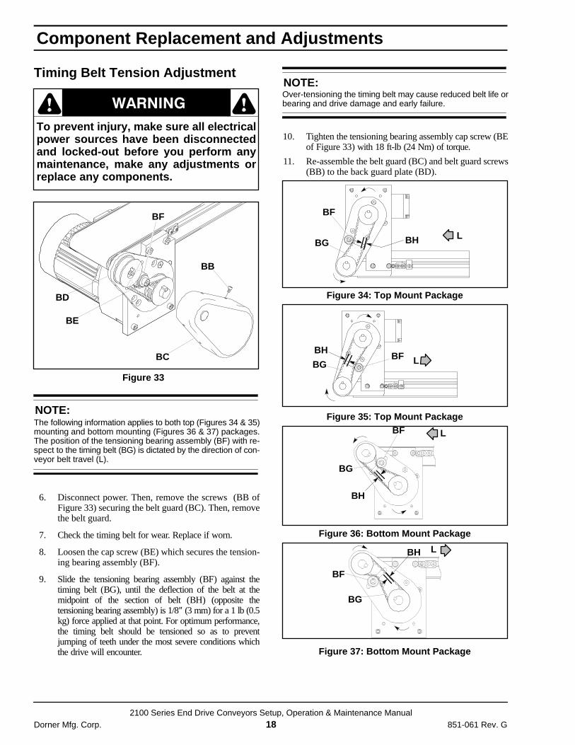
Timing Belt Tension Adjustment
To prevent injury, make sure all electricalpower sources have been disconnectedand locked-out before you perform anymaintenance, make any adjustments orreplace any components.
Ç Ç
Figure 33
BD
BE
BB
BC
BF
NOTE:The following information applies to both top (Figures 34 & 35)mounting and bottom mounting (Figures 36 & 37) packages.The position of the tensioning bearing assembly (BF) with re-spect to the timing belt (BG) is dictated by the direction of con-veyor belt travel (L).
6. Disconnect power. Then, remove the screws (BB ofFigure 33) securing the belt guard (BC). Then, removethe belt guard.
7. Check the timing belt for wear. Replace if worn.
8. Loosen the cap screw (BE) which secures the tension-ing bearing assembly (BF).
9. Slide the tensioning bearing assembly (BF) against thetiming belt (BG), until the deflection of the belt at themidpoint of the section of belt (BH) (opposite thetensioning bearing assembly) is 1/8″ (3 mm) for a 1 lb (0.5kg) force applied at that point. For optimum performance,the timing belt should be tensioned so as to preventjumping of teeth under the most severe conditions whichthe drive will encounter.
NOTE:Over-tensioning the timing belt may cause reduced belt life orbearing and drive damage and early failure.
10. Tighten the tensioning bearing assembly cap screw (BEof Figure 33) with 18 ft-lb (24 Nm) of torque.
11. Re-assemble the belt guard (BC) and belt guard screws(BB) to the back guard plate (BD).
Figure 34: Top Mount Package
BF
BG BH L
BF
Figure 35: Top Mount Package
BG
BHL
Figure 36: Bottom Mount Package
BG
BF
BH
L
Figure 37: Bottom Mount Package
BF
BG
BH L
Component Replacement and Adjustments

2100 Series End Drive Conveyors Setup, Operation & Maintenance ManualDorner Mfg. Corp. 19 851-061 Rev. G
Bearings
Problem Possible Cause SolutionBearing failure Grit getting into bearing. Side wipers and bottom wiper may be needed
along with increased frequency of lubrication.
Solvent getting into bearings. Same as above. Keep greasing adapters inretaining sleeves. Install guards and tilt conveyorto reduce amount of solvent on conveyor.
Drive shaft misaligned or excessive side force onshaft and couplings.
Be sure spindle, sleeves and bearings arecorrectly installed and shaft is aligned. Flexible orUniversal couplings may be required.
Excessive heat in application. Increase frequency of lubrication.
Damage due to improper re-assembly. Use tool kit for proper re-assembly.
Bearing seizure. Grit getting into bearings. Failure to lubricatebearings periodically.
Lubricate bearings periodically.
Gearmotors
Remove power before attempting to re-wiremotor or system electrical control.
Ç Ç
Problem Possible Cause SolutionMotor cuts outintermittently.
Overloading. Check conveyor load. Use torque wrench todetermine input torque. Check for guides oraccessories rubbing on belt. Check belt tracking.
Improper cooling. Check motor operation and ambient temperature.
Motor running hot,above 170°F (77°C).
Overloading. Check amperage draw, replace motor, reduceconveyor load.
Jammed part. Remove jam.
Incorrect voltage/wiring. Check wiring diagram. Replace motor or changewiring.
Improper cooling. Reduce excessive ambient temperature.
Conveyor runs in wrongdirection.
Improper wiring. Check wiring diagram.
Troubleshooting Guide

2100 Series End Drive Conveyors Setup, Operation & Maintenance ManualDorner Mfg. Corp. 20 851-061 Rev. G
Conveyor Belt
Problem Possible Cause SolutionBelt slipping. Belt is too loose. Adjust belt tension. If belt is still loose, replace belt.
Note: Belt may have stretched. See “Beltstretching” problem below.
Dirt impacted in knurl on end of driven spindle. Clean spindle.
Knurl worn on spindle. Replace spindle.
Excessive weight on conveyor. Note: May be acombination of drive “pushing” belt ormagnets too strong for application.
Reduce weight on conveyor by reducingproduction rate, or increasing belt speed.
Drive is “pushing” belt. Note: May be acombination of this and excessive weight onconveyor.
Move end drive to discharge end of conveyor.Turn center drive 180° so gearmotor and drivenspindle are towards discharge end.
Magnets too strong for application. Increase belt speed or replace magnetic bedplate.
Debris wedged in belt path or in conveyor. Clean conveyor and install chute and/or wipers.
Belt stretching. Solvent or chemical reaction with belt. Remove solvent or try a different belt material.Test solvent with belt sample. Note: A belt-typeconveyor may not be applicable.
Belt repeatedly stalled, causing spindle to wear or“burn” in to backside of belt.
Replace belt and identify reason for stalling.
Cuts on belt surface. Parts getting caught in bottom wiper Replace wiper.
Bottom wiper is damaged, missing or on wrongend of the conveyor.
Replace wiper. Note: Conveyor belt shouldalways be run towards bottom wiper.
Parts getting under belt. Wiper shears top surfaceleaving marks in belt surface.
High sides, side wipers or side deflectors may beneeded.
Side wipers damaged or missing which is allowingmaterial to get under belt.
Replace or add wipers, as needed.
Sharp parts penetrating belt surface. Install baffle to reduce energy of falling part.
Guides or accessories rubbing on belt. Re-adjust guides, as necessary.
Worn belt edges. Debris impacted on spindles causing belt trackingproblems.
Clean spindles. Correct source of contamination.See “Belt tracking incorrectly” problem below.
Belt tracking incorrectly. Refer to the “Conveyor Belt Tracking” topicbeginning on page 14.
Belt breaking at splice. Solvent or chemical reaction with belt. Remove solvent or try a different belt material.Test solvent with belt sample. Note: A belt-typeconveyor may not be applicable.
Belt trackingincorrectly.
Spindles not perpendicular to conveyor center line. Inspect spindles and/or sleeves. Repositionspindles or reinstall sleeves, if necessary.
Frame misalignment. Note: Frame mountingsurface may be misaligned.
Frame mounting must be straight and in sameplane. Check this with a straight edge and level.
Frame distortion due to damage. Repair or replace frame components and/or bedplate. Check with a straight edge.
Side force being applied to belt. Check for jammed part or mechanical pusherforce on belt.
Belt tracking cam incorrectly adjusted. Refer to the “Conveyor Belt Tracking” topicbeginning on page 14.
Timing Belt
Problem Possible Cause SolutionIntermittent conveyorbelt travel.
Timing belt is too loose. Adjust belt tension. Refer to “Timing Belt TensionAdjustment for Top or Bottom Mounting Packagestopic on page 18.
Worn or damaged timing (drive) belt. Replace defective timing belt.
TroubleshootingGuide

Replacement Parts
2100 Series Conveyors Parts, Assembly & Maintenance ManualDorner Mfg. Corp. 21 851-061 Rev. G
Conveyor Belt Part Number
DD– WWLL/ BB
Belt Type: See below.
Nominal Conveyor Length in feet.
Nominal Belt Width in inches.
Conveyor Type End Drive = 21
EXAMPLE: #2 Standard Urethane replacement belt for anend drive conveyor measuring 4″ (102 mm) wide x 8ft (2,438 mm) long would be Part Number21-0408/02.
Belt Type - BB/01 Accumulator Top FDA Approved 80-90 Durometer
surface hardness. Products may be accumulated onthe low friction surface of this belt. Maximum parttemperature is 176 °F (80 °C). Smooth, thermallywelded zig-zag splice*. Belt thickness about 0.063″(1.6 mm).
/02 Standard Urethane 75-85 Durometer surfacehardness. This is our standard belting, very durableand works well in most applications. Maximum parttemperature is 212 °F (100 °C). Smooth, thermallywelded zig-zag splice*. Belt thickness about 0.071″(1.8 mm).
/03 Soft Urethane FDA Approved 70-80 Durometersurface hardness. This belt provides more surfacefriction and is more resistant to chemicals than /01 or/02. Maximum part temperature is 176 °F (80 °C).Smooth, thermally welded zig-zag splice*. Beltthickness about 0.063″ (1.6 mm).
/05 Woven Polyester Belt Offers advantages in lowfriction product accumulation. Maximum parttemperature is 212 °F (100 °C). Smooth, thermallywelded zig-zag splice*. Belt thickness about 0.047″(1.2 mm).
/06 Black Anti-Static Belt Is a carbon impregnatedpolyester belt used where an anti-static/conductivebelt is required. Belt should be tested per applicationfor resistance to ground. Maximum part temperature
is 230 °F (110 °C). Smooth, thermally welded zig-zagsplice*. Belt thickness about 0.063″ (1.6 mm).
/07 Heat Resistant Belt This belt resists producttemperatures up to 358 �F (180 °C). Smooth,thermally welded zig-zag splice*. Belt thickness about0.051″ (1.3 mm).
/08 High Friction Belt This belt provides a high degree ofsurface traction when clean and dry. It can be used toconvey parts up inclines or in other applications whereparts must not slide on the belt surface. This beltshould not be used with very small or sharp parts.Maximum part temperature is 158 °F (70 °C). Smooth,thermally welded zig-zag splice*. Belt thickness about0.083″ (2.1 mm).
NOTE:08 High Friction Belt cannot be used with 03 and/or 06Side Profiles.
NOTE:All belts include a thermally welded finger splice. IfClipper spliced belt is required, add a “-C” suffix.
EXAMPLE: Part No 21-0408/02-C
NOTE:For replacement belting on vacuum, cleated andspecially modified conveyors, contact factory with model& order numbers for replacement information.
IMPORTANT:If switching from Belt Types 01, 02, 05 or 07 to BeltTypes 03, 04 or 06 you must remove and the originalBottom Wiper, Item 7 on page 22 and replace it with aBottom Bar, Item 6 on page 22.

Replacement Parts
2100 Series Conveyors Parts, Assembly & Maintenance ManualDorner Mfg. Corp. 22 851-061 Rev. G
NOTE:For replacement parts, other than those shown on thispage, contact the factory.
Drive / Idler Pulleys
1
2
27
63
5
4
Item Part No. Part Description1 See Chart Pulley Assembly2 200035 Retaining Sleeve3 200027 Tail Plate, Low Side, SAE
200027M Tail Plate, Low Side, Metric4 200028 Tail Plate, Low Side, SAE
200028M Tail Plate, Low Side, Metric5 200030 Cover Plate, SAE
200030M Cover Plate, Metric6 203602 Bottom Bar, 2” Wide
203603 Bottom Bar, 3” Wide203604 Bottom Bar, 4” Wide203605 Bottom Bar, 5” Wide203606 Bottom Bar, 6” Wide203608 Bottom Bar, 8” Wide203610 Bottom Bar, 10” Wide203612 Bottom Bar, 12” Wide203618 Bottom Bar, 18” Wide203621 Bottom Bar, 21” Wide203624 Bottom Bar, 24” Wide
7 203502 Bottom Wiper, 2” Wide203503 Bottom Wiper, 3” Wide203504 Bottom Wiper, 4” Wide203505 Bottom Wiper, 5” Wide203506 Bottom Wiper, 6” Wide203508 Bottom Wiper, 8” Wide203510 Bottom Wiper, 10” Wide203512 Bottom Wiper, 12” Wide203518 Bottom Wiper, 18” Wide203521 Bottom Wiper, 21” Wide203524 Bottom Wiper, 24” Wide
21–33
21–33
8
Part Number
NominalConveyor
Width
Drive/Idler PulleyAssembly (1) with
21-33 BearingsDrive/Idler
Pulley Only (8)1.75” (44 mm) 204802 Not Applicable2.75” (70 mm) 204803 2047033.75” (95 mm) 204804 2047045” (127 mm) 204805 2047056” (152 mm) 204806 2047067” (203 mm) 204808 2047088” (254 mm) 204810 20471010” (305 mm) 204812 20471218” (457 mm) 204818 20471821” (533 mm) 204821 20472124” (610 mm) 204824 204724
Hex to Round Adapter Assembly
9
11
10
Part Number
Conveyor-Width
Drive ShaftAssembly(9)
OutboardBearingRetainingSleeve(10)
GreaseFitting(11)
1.75” (44mm) 216202M 200223 N/A
2.75” (70mm) 216203M 200223 810–292
3.75” to 12”(95–305mm)
216204M 200223 810–292
18” to 24”(457–610mm)
216205M 200223 810–292

Replacement Parts
2100 Series Conveyors Parts, Assembly & Maintenance ManualDorner Mfg. Corp. 23 851-061 Rev. G
Flat Belt Return Rollers
12
13
14
13
Item Part No. Part Description12 202348P Bearing Pin
13 202311P Return Roller Bearing
14 207702 Return Roller Tube, 2” (44 mm) Long
207703 Return Roller Tube, 3” (70 mm) Long
207704 Return Roller Tube, 4” (95 mm) Long
207705 Return Roller Tube, 5” (127 mm) Long
207706 Return Roller Tube, 6” (152 mm) Long
207708 Return Roller Tube, 8” (203 mm) Long
207710 Return Roller Tube, 10” (254 mm) Long
207712 Return Roller Tube, 12” (305 mm) Long
207718 Return Roller Tube, 18” (457 mm) Long
207724 Return Roller Tube, 24” (610 mm) Long
Cleated Belt Return Rollers
15
Item Part No. Part Description
15 802-027 Sealed Ball Bearing

No returns will be accepted without prior written factory authorization. When calling for authorization, pleasehave the following information ready for the Dorner Factory representative or your local distributor:
1. Name and address of customer.
2. Item(s) being returned.
3. Reason for return.
4. Customer’s original order number used when ordering the item(s).
5. Dorner or distributor invoice number.
A representative will discuss action to be taken on the Returned items and provide a Returned GoodsAuthorization Number to reference.
There will be a 15% restocking charge on all new items returned for credit where Dorner was not at fault. Thesewill not be accepted after 60 days from original invoice date. The restocking charge covers inspection, cleaning,disassembly, and reissuing to inventory.If a replacement is needed prior to evaluation of returned item, a purchase order must be issued. Credit(if any) is issued only after return and evaluation is complete.
Dorner has representatives throughout the world. Feel free to contact Dorner for the name of your localrepresentative. Our technical sales and service staff will gladly help with your questions on Dorner products.
For a copy of Dorner’s Limited Warranty, contact factory, distributor, service center or visit our website atwww.dorner.com.
851-061 Rev. G Printed in U.S.A. 200
975 Cottonwood Ave., PO Box 20Hartland, WI 53029-0020 USA
Dorner Mfg. Corp. reserves the right to change ordiscontinue products without notice. All products andservices are covered in accordance with our standardwarranty. All rights reserved. Dorner Mfg. Corp. 2000
DORNERArnold-Sommerfeld-Ring 2D-52499 Baesweiler
USATEL 1-800-397-8664 (USA) FAX 1-800-369-2440 (USA)
GermanyTEL (02401) 80 52 90FAX (02401) 80 52 93
Internet: www.dorner.comOutside the USA:TEL 1-262-367-7600, FAX 1-262-367-5827
DORNER MFG. CORP.
For replacement parts, contact an authorizedDorner Service Center or the factory.
Return Policy