
Setup-Manual - Mikado Model Helicopters GmbH Control...Setup Manual Mikado Model Helicopters GmbH...
18
Setup-Manual
Transcript of Setup-Manual - Mikado Model Helicopters GmbH Control...Setup Manual Mikado Model Helicopters GmbH...
Setup-Manual

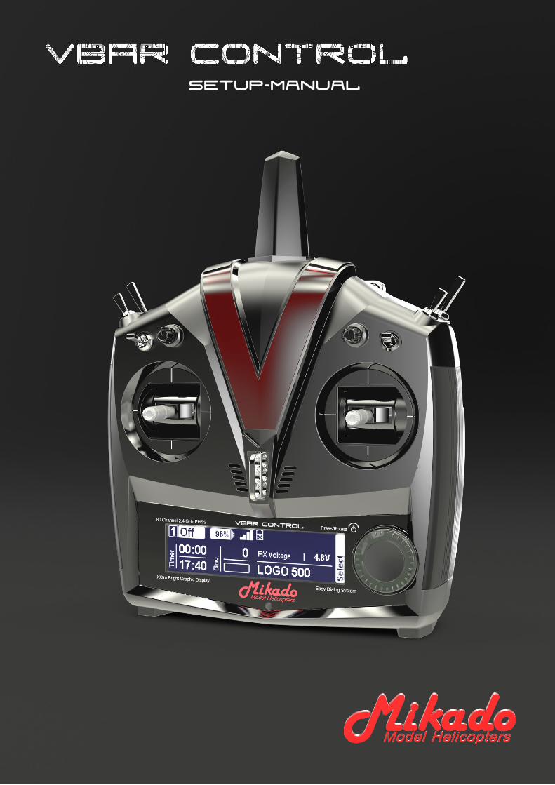
VBar Control Setup Manual
Mikado Model Helicopters GmbHFriedrich-Klausing-Str. 2 · 14469 Potsdam · GermanyTelefon +49 331 23749-0 · Telefax +49 331 23749-11
[email protected] · www.mikado-heli.de© Mikado Model Helicopters 2014. All rights reserved.
v1.01 05-2014
4
Table of Contents
Getting Started 5
Updating an existing VBar or Mini VBar to communicate with your VBar Control Transmitter . . . . . . . . . . . . . . 5
Basic Setup using the Wizard 6
Express-Version, Mikado LOGO series . . . 6
Express-Version, non-Mikado helis . . . . . . 8
ESC Setup Wizard 11
YGE 90 LV and similar with 0LNDGR�2(0�¿UPZDUH� for stick programming . . . . . . . . . . . . . . . 11
Kontronik ESCs . . . . . . . . . . . . . . . . . . . . 12
Unknown/other ESCs. . . . . . . . . . . . . . . . 13
General Settings 14
Express/Basic Setup . . . . . . . . . . . . . . . . 14
Mainrotor Parameters . . . . . . . . . . . . . . . 14
Tailrotor Parameters. . . . . . . . . . . . . . . . . 15
Governor . . . . . . . . . . . . . . . . . . . . . . . . . 15
Model Status . . . . . . . . . . . . . . . . . . . . . . 15
Tail-Servo List . . . . . . . . . . . . . . . . . . . . . 16
VBar and Mini VBar 17
Safety Instructions . . . . . . . . . . . . . . . . . . 17
Wiring your VBar/Mini VBar . . . . . . . . . . . 17
Initialization . . . . . . . . . . . . . . . . . . . . . . . 17
Pre-Flight Check . . . . . . . . . . . . . . . . . . . 17
Exemption from Liability. . . . . . . . . . . . . . 17
Accessories . . . . . . . . . . . . . . . . . . . . . . . 17
5
Getting Started
Ļ Attention When promped by the wizard, you have to re-set the servo arms during model setup of VBar Control to get them as close to the actual center postion as possible.
Ļ Attention Disconnect and remove the receiver of your old radio system from the helicopter.
ľ Danger Disconnect the ESC or move the motor away from the main gear. This is to avoid the model accidentally spooling up during the setup process.
Ļ Attention On battery-powered helicopters, the ESC must ALWAYS must be connected to ‘Colle/ESC’ on a fullsize VBar with external sensor. In case it was connected to CH4 or Servo, please re-connect. On a Mini VBar, the ESC is always connected to RX B.
Ļ Attention On nitro-powered helicopters, the throttle servo must ALWAYS be conntected to Servo (on fullsize VBars with external sensor). In case it was connected to CH4 or Colle/ESC, please re-connect.
ľ Danger Remove main rotor blades and tail rotor blades during setup and initial tests of the power unit and gover-nor.
Ļ Attention After the update has been completed, the VBar is no longer accessible and can no longer be set up using WKH�3&�VRIWZDUH��7R�SHUIRUP�DQ�XSGDWH�WR�D�QHZHU���[�¿UP-ZDUH��\RX�PXVW�ORDG�WKH�UHFRYHU\�¿UPZDUH�¿UVW��VHH�)$4�on www.vstabi.info).
Ļ Attention In case of an update gone wrong (interruption of the process, e.g. due to battery failure, computer crash, accidental disconnection of the USB lead or similar), please VHH�RXU�)$4�RQ�ZZZ�YVWDEL�LQIR� RQ�KRZ� WR� UHFRYHU� \RXU�VBar and start over.
Ļ Attention 7R�VZLWFK�EDFN�WR�9%DU�¿UPZDUH�IRU�XVH�ZLWK�UD-GLRV�RWKHU�WKDQ�9%DU�&RQWURO��VHH�RXU�)$4�RQ�ZZZ�YVWDEL�info on how to recover your VBar. After recovery, select an DSSURSULDWH�¿UPZDUH�IURP�WKH�OLVW�LQ�µ)LOH�2QOLQH�8SGDWH¶�RI�the 5.x+ PC software. If necessary, get a license key from www.vstabi.info.
Ļ Attention You must create a new setup using the VBar &RQWURO¶V�VHWXS�ZL]DUGV�IRU�HYHU\�9%DU�\RX�FRQYHUW�WR�¿UP-ware version 6.x. Parameters will not be transferred on an DOUHDG\�VHW�XS���[�RU���[�9%DU��6HWXS�¿OHV�IURP�ROGHU�YHU-VLRQV�RI�WKH�9%DU�VRIWZDUH�DQG�¿UPZDUH�DUH�QRW�FRPSDWLEOH��and can not be loaded into the VBar by copying on the VBar Control’s internal memory.
Ļ Attention VBar Control has only Apps for basic setup and ÀLJKW� RSHUDWLRQV� LQVWDOOHG� E\� GHIDXOW�� 5HJLVWHU� \RXU� 9%DU�Control (see page 18 of the device manual) to access the App Store on www.vstabi.info (click on ‘Applications’ in the VBar Control Manager).
Updating an existing VBar or Mini VBar to communi-cate with your VBar Control Transmitter
Ļ Attention Do not connect the VBar Control Receiver Satel-lite yet. You may either connect the USB wire or a device to the Bluetooth/Control Panel connector, but not both.
Ŷ� Log in to www.vstabi.info using your MikadoID (please check out our video tutorials on www.vstabi.info if you are not yet familiar with registration and online update of VBar Flybarless Controllers).
Ŷ� Navigate to ‘My VBars’, check the list of devices regis-tered to your MikadoID.
Ŷ� If needed, register a new or used device to your Mika-GR,'�¿UVW�
Ŷ� Click on the magnifying glass in the column ‘Options’ for the VBar in question. Click ‘Add VBar Control Version’ to HQDEOH�WKH�UHTXLUHG�¿UPZDUH�
Ŷ� Click on the globe icon below ‘License’ to get a license key for the device in question. You will receive an e-mail with a one-time link shortly.
Ŷ� Click the link in the e-mail and follow the instructions on the screen.
Ŷ� Use PC software 5.3+ (download available on www.vstabi.info) to perform File/Online Update for the device.
Ŷ� 6HOHFW���[�¿UPZDUH��FOLFN�µ/RDG¶��:DLW�IRU�WKH�XSGDWH�WR�install, do not disconnect the VBar during the process. 0DNH�VXUH�\RXU�UHFHLYHU�SRZHU�VXSSO\�LV�VXI¿FLHQW�DQG�WKDW�WKH�86%�OHDG�LV�¿UPO\�SOXJJHG�LQWR�WKH�9%DU��PLQG�the rubber protector especially on a Mini VBar).
Ŷ� Turn off your VBar, disconnect the USB lead.
Ļ Only now connect the VBar Control Receiver Satellite.
Ŷ� Turn on your VBar again (wait for 10 seconds: this will bring the VBar Control Receiver Satellite into Bind Mode).
Ŷ� Turn on your VBar Control Transmitter.Ŷ� Select Transmitter Setup, Bind from the menu.Ŷ� Select the VBar (serial number) of the VBar you are
about to set up.
6
Basic Setup using the Wizard
Express-Version, Mikado LOGO series
Ļ Attention 7KLV�VSHFL¿F�:L]DUG�DVVXPHV�WKDW�WKH�KHOL�LV�EXLOW�according to the manual (e.g. leading/trailing edge control of the main and tail rotor, mounting position of servos, dis-tance of ball links on servo arms, direction of rotation on main and tail rotor etc.).
Ļ Attention Disconnect all servos on an already set-up mod-el and disconnect the ball links to the swash plate and the tail rotor push rod. This is to avoid damage to the tail servo and to the mechanics during the setup process.
Ļ Attention A VBar that is connected to the VBar Control 6\VWHP�IRU�WKH�¿UVW�WLPH�ZLOO�DXWRPDWLFDOO\�FDXVH�WKH�VHWXS�wizard to start. A VBar that has already been connected to a VBar Control System will just connect. In this case, select Heli Setup Wizard from Model Setup, Setup Tools in the menu to start the setup process.
Ļ Attention )RU�/2*2�VHULHV�KHOLFRSWHUV��WKH�FROOHFWLYH�DQG�cyclic values will be set automatically to factory defaults. This requires the heli to be set up by following the manual exactly. To check or to make changes to the setup accord-ing to your personal wishes or taste, re-enter the Heli Setup Wizard again after the initial setup and select Edit Current Model.
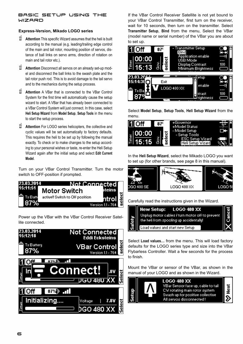
Turn on your VBar Control Transmitter. Turn the motor switch to OFF-position if prompted.
Power up the VBar with the VBar Control Receiver Satel-lite connected.
If the VBar Control Receiver Satellite is not yet bound to \RXU�9%DU�&RQWURO�7UDQVPLWWHU�� ¿UVW� WXUQ� RQ� WKH� UHFHLYHU��wait for 10 seconds, then turn on the transmitter. Select Transmitter Setup, Bind from the menu, Select the VBar (model name or serial number) of the VBar you are about to set up.
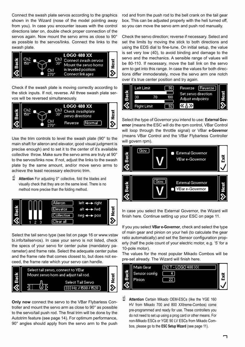
Select Model Setup, Setup Tools, Heli Setup Wizard from the menu.
In the Heli Setup Wizard, select the Mikado LOGO you want to set up (for other brands, see page 8 in this manual).
Carefully read the instructions given in the Wizard.
Select Load values… from the menu. This will load factory defaults for the LOGO series type and size into the VBar Flybarless Controller. Wait a few seconds for the process WR�¿QLVK�
Mount the VBar or sensor of the VBar, as shown in the manual of your LOGO and as shown in the Wizard.
7
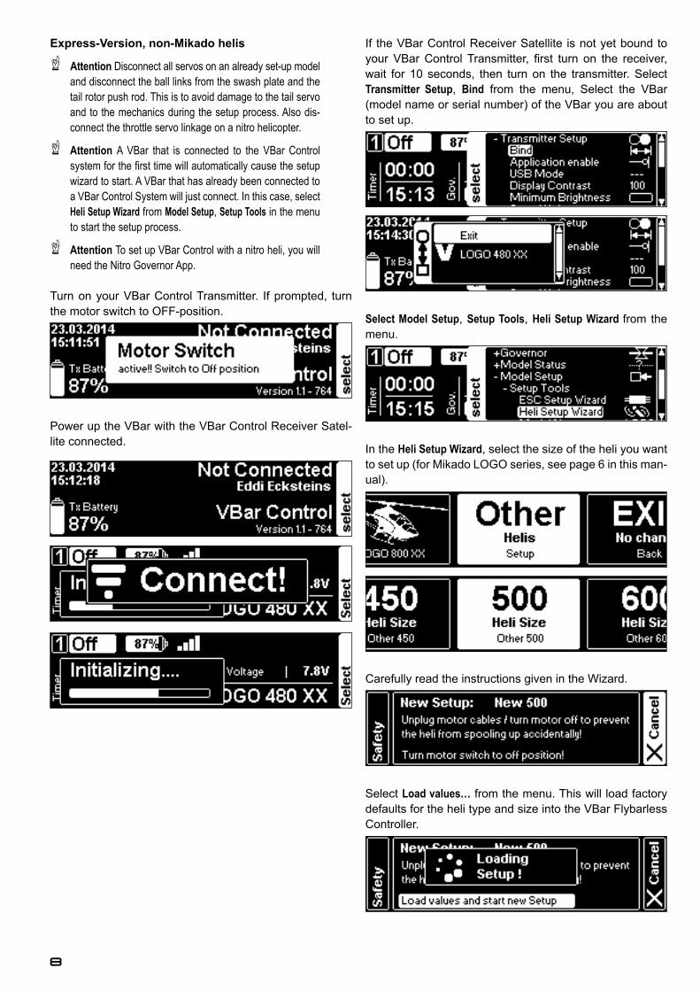
Connect the swash plate servos according to the graphics shown in the Wizard (nose of the model pointing away from you). In case you encounter issues with the control directions later on, double check proper connection of the servos again. Now mount the servo arms as close to 90° as possible to the servos/links. Connect the links to the swash plate.
Check if the swash plate is moving correctly according to the stick inputs. If not, reverse. All three swash plate ser-vos will be reversed simultaneously.
Use the trim controls to level the swash plate (90° to the main shaft for aileron and elevator, good visual judgment is precise enough) and to set it to the center of it’s available collective throw. Make sure the servo arms are truly at 90° to the servos/links now. If not, adjust the links to the swash plate by the same amount, and/or move servo arms to achieve the least necessary electronic trim.
Ļ Attention )RU�DGMXVWLQJ����FROOHFWLYH��IROG�WKH�EODGHV�DQG�visually check that they are on the same level. There is no method more precise than the folding method.
Select the tail servo type (see list on page 16 or www.vstav-bi.info/tailservos). In case your servo is not listed, check the specs of your servo for center pulse (mandatory pa-rameter) and frame rate. Select the adequate center pulse and the frame rate that comes closest to, but does not ex-ceed, the frame rate which your servo can handle.
Only now connect the servo to the VBar Flybarless Con-troller and mount the servo arm as close to 90° as possible WR�WKH�VHUYR�WDLO�SXVK�URG��7KH�¿QDO�WULP�ZLOO�EH�GRQH�E\�WKH�Autotrim feature (see page 14). For optimum performance, 90° angles should apply from the servo arm to the push
rod and from the push rod to the bell crank on the tail gear box. This can be adjusted properly with the heli turned off, so you can move the servo arm and push rod manually.
Check the servo direction; reverse if necessary. Select and set the limits by moving the stick to both directions and XVLQJ�WKH�('6�GLDO�WR�¿QH�WXQH��2Q�LQLWLDO�VHWXS��WKH�YDOXH�is set very low (40), to avoid binding and damage to the servo and the mechanics. A sensible range of values will be 80-110. If necessary, move the ball link on the servo arm to get into this range. In case the values for both direc-tions differ immoderately, move the servo arm one notch over it’s true center position and try again.
Select the type of Governor you intend to use: External Gov-ernor (means the ESC will do the rpm control, VBar Control will loop through the throttle signal) or VBar e-Governor (means VBar Control and the VBar Flybarless Controller will govern rpm).
In case you select the External Governor, the Wizard will ¿QLVK�KHUH��&RQWLQXH�VHWWLQJ�XS�\RXU�(6&�RQ�page 11.
If you you select VBar e-Governor, check and select the type of main gear and pinion on your heli (to calculate the gear UDWLR�DXWRPDWLFDOO\��DQG�VHW�WKH�6HQVRU�FRQ¿JXUDWLRQ�SURS-erly (half the pole count of your electric motor, e.g. ‘5’ for a 10-pole motor).The values for the most popular Mikado Combos will be SUH�VHW�DOUHDG\��7KH�:L]DUG�ZLOO�¿QLVK�KHUH�
Ļ Attention &HUWDLQ�0LNDGR�2(0�(6&V� �OLNH� WKH�<*(�����+9� IURP� 0LNDGR� ���� DQG� ���� ;;WUHPH�&RPERV�� FRPH�pre-programmed and ready for use. These controllers you GR�QRW�QHHG�WR�VHW�XS�XVLQJ�D�SURJ�FDUG�RU�RWKHU�PHDQV��)RU�QRQ�0LNDGR�(6&V�RU�<*(����/9�(6&V�IURP�0LNDGR�&RP-bos, please go to the ESC Setup Wizard (see page 11).
8
Express-Version, non-Mikado helis
Ļ Attention Disconnect all servos on an already set-up model and disconnect the ball links from the swash plate and the tail rotor push rod. This is to avoid damage to the tail servo and to the mechanics during the setup process. Also dis-connect the throttle servo linkage on a nitro helicopter.
Ļ Attention A VBar that is connected to the VBar Control V\VWHP�IRU�WKH�¿UVW�WLPH�ZLOO�DXWRPDWLFDOO\�FDXVH�WKH�VHWXS�wizard to start. A VBar that has already been connected to a VBar Control System will just connect. In this case, select Heli Setup Wizard from Model Setup, Setup Tools in the menu to start the setup process.
Ļ Attention To set up VBar Control with a nitro heli, you will QHHG�WKH�1LWUR�*RYHUQRU�$SS�
Turn on your VBar Control Transmitter. If prompted, turn the motor switch to OFF-position.
Power up the VBar with the VBar Control Receiver Satel-lite connected.
If the VBar Control Receiver Satellite is not yet bound to \RXU�9%DU�&RQWURO�7UDQVPLWWHU�� ¿UVW� WXUQ� RQ� WKH� UHFHLYHU��wait for 10 seconds, then turn on the transmitter. Select Transmitter Setup, Bind from the menu, Select the VBar (model name or serial number) of the VBar you are about to set up.
Select Model Setup, Setup Tools, Heli Setup Wizard from the menu.
In the Heli Setup Wizard, select the size of the heli you want to set up (for Mikado LOGO series, see page 6 in this man-ual).
Carefully read the instructions given in the Wizard.
Select Load values… from the menu. This will load factory defaults for the heli type and size into the VBar Flybarless Controller.
9
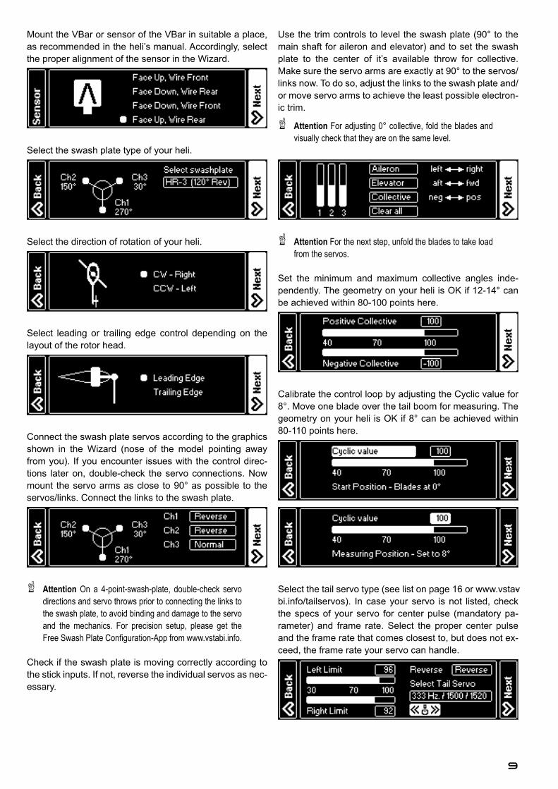
Mount the VBar or sensor of the VBar in suitable a place, as recommended in the heli’s manual. Accordingly, select the proper alignment of the sensor in the Wizard.
Select the swash plate type of your heli.
Select the direction of rotation of your heli.
Select leading or trailing edge control depending on the layout of the rotor head.
Connect the swash plate servos according to the graphics shown in the Wizard (nose of the model pointing away from you). If you encounter issues with the control direc-tions later on, double-check the servo connections. Now mount the servo arms as close to 90° as possible to the servos/links. Connect the links to the swash plate.
Ļ Attention On a 4-point-swash-plate, double-check servo directions and servo throws prior to connecting the links to the swash plate, to avoid binding and damage to the servo DQG� WKH� PHFKDQLFV�� )RU� SUHFLVLRQ� VHWXS�� SOHDVH� JHW� WKH�)UHH�6ZDVK�3ODWH�&RQ¿JXUDWLRQ�$SS�IURP�www.vstabi.info.
Check if the swash plate is moving correctly according to the stick inputs. If not, reverse the individual servos as nec-essary.
Use the trim controls to level the swash plate (90° to the main shaft for aileron and elevator) and to set the swash plate to the center of it’s available throw for collective. Make sure the servo arms are exactly at 90° to the servos/links now. To do so, adjust the links to the swash plate and/or move servo arms to achieve the least possible electron-ic trim.
Ļ Attention )RU�DGMXVWLQJ����FROOHFWLYH��IROG�WKH�EODGHV�DQG�visually check that they are on the same level.
Ļ Attention )RU�WKH�QH[W�VWHS��XQIROG�WKH�EODGHV�WR�WDNH�ORDG�from the servos.
Set the minimum and maximum collective angles inde-pendently. The geometry on your heli is OK if 12-14° can be achieved within 80-100 points here.
Calibrate the control loop by adjusting the Cyclic value for 8°. Move one blade over the tail boom for measuring. The geometry on your heli is OK if 8° can be achieved within 80-110 points here.
Select the tail servo type (see list on page 16 or www.vstav-bi.info/tailservos). In case your servo is not listed, check the specs of your servo for center pulse (mandatory pa-rameter) and frame rate. Select the proper center pulse and the frame rate that comes closest to, but does not ex-ceed, the frame rate your servo can handle.
10
Only now connect the servo to the VBar Flybarless Con-troller and mount the servo arm as close to 90° as possible WR�WKH�VHUYR�WDLO�SXVK�URG��7KH�¿QDO�WULP�ZLOO�EH�GRQH�E\�WKH�Autotrim feature (see page 14). For optimum performance, 90° angles should apply from the servo arm to the push rod and from the push rod to the bell crank on the tail gear box. This can be adjusted properly with the heli turned off, so you can move the servo arm and push rod manually.Check the servo direction, reverse if necessary. Select and set the limits by moving the stick to both directions and XVLQJ�WKH�('6�GLDO�WR�¿QH�WXQH��2Q�LQLWLDO�VHWXS��WKH�YDOXH�is set very low (40) to avoid binding and damage to the servo and the mechanics. A sensible range of values will be 80-110. If necessary, move the ball link on the servo arm to get into this range. In case the values for both direc-tions differ immoderately, move the servo arm one notch over it’s true center position and try again.
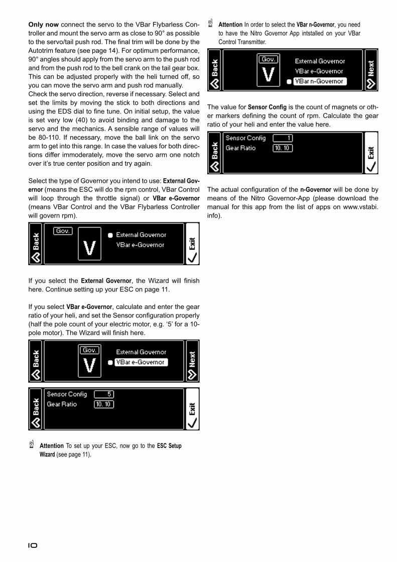
Select the type of Governor you intend to use: External Gov-ernor (means the ESC will do the rpm control, VBar Control will loop through the throttle signal) or VBar e-Governor (means VBar Control and the VBar Flybarless Controller will govern rpm).
If you select the External Governor�� WKH�:L]DUG�ZLOO� ¿QLVK�here. Continue setting up your ESC on page 11.
If you select VBar e-Governor, calculate and enter the gear UDWLR�RI�\RXU�KHOL��DQG�VHW�WKH�6HQVRU�FRQ¿JXUDWLRQ�SURSHUO\�(half the pole count of your electric motor, e.g. ‘5’ for a 10-SROH�PRWRU���7KH�:L]DUG�ZLOO�¿QLVK�KHUH�
Ļ Attention To set up your ESC, now go to the ESC Setup Wizard (see page 11).
Ļ Attention In order to select the VBar n-Governor, you need WR� KDYH� WKH� 1LWUR� *RYHUQRU�$SS� LQWVWDOOHG� RQ� \RXU� 9%DU�Control Transmitter.
The value for 6HQVRU�&RQ¿J is the count of magnets or oth-HU�PDUNHUV�GH¿QLQJ� WKH�FRXQW�RI� USP��&DOFXODWH� WKH�JHDU�ratio of your heli and enter the value here.
7KH�DFWXDO�FRQ¿JXUDWLRQ�RI�WKH�n-Governor will be done by means of the Nitro Governor-App (please download the manual for this app from the list of apps on www.vstabi.info).
11
ESC Setup Wizard
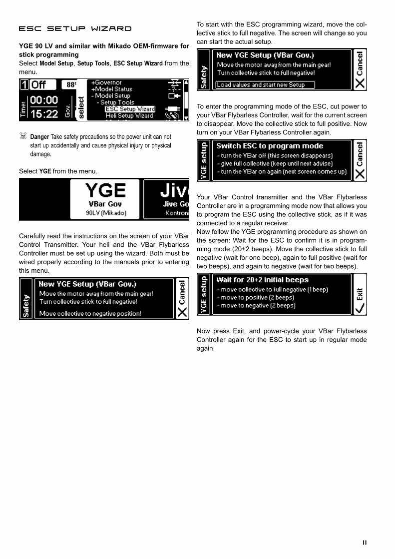
<*(����/9�DQG�VLPLODU�ZLWK�0LNDGR�2(0�¿UPZDUH�IRU�stick programmingSelect Model Setup, Setup Tools, ESC Setup Wizard from the menu.
ľ Danger Take safety precautions so the power unit can not start up accidentally and cause physical injury or physical damage.
Select YGE from the menu.
Carefully read the instructions on the screen of your VBar Control Transmitter. Your heli and the VBar Flybarless Controller must be set up using the wizard. Both must be wired properly according to the manuals prior to entering this menu.
To start with the ESC programming wizard, move the col-lective stick to full negative. The screen will change so you can start the actual setup.
To enter the programming mode of the ESC, cut power to your VBar Flybarless Controller, wait for the current screen to disappear. Move the collective stick to full positive. Now turn on your VBar Flybarless Controller again.
Your VBar Control transmitter and the VBar Flybarless Controller are in a programming mode now that allows you to program the ESC using the collective stick, as if it was connected to a regular receiver.Now follow the YGE programming procedure as shown on WKH�VFUHHQ��:DLW� IRU� WKH�(6&�WR�FRQ¿UP� LW� LV� LQ�SURJUDP-ming mode (20+2 beeps). Move the collective stick to full negative (wait for one beep), again to full positive (wait for two beeps), and again to negative (wait for two beeps).
Now press Exit, and power-cycle your VBar Flybarless Controller again for the ESC to start up in regular mode again.
12
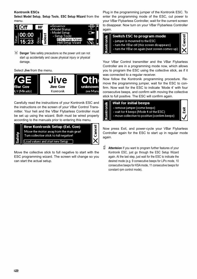
Kontronik ESCsSelect Model Setup, Setup Tools, ESC Setup Wizard from the menu.
ľ Danger Take safety precautions so the power unit can not start up accidentally and cause physical injury or physical damage.
Select Jive from the menu.
Carefully read the instructions of your Kontronik ESC and the instructions on the screen of your VBar Control Trans-mitter. Your heli and the VBar Flybarless Controller must be set up using the wizard. Both must be wired properly according to the manuals prior to entering this menu.
Move the collective stick to full negative to start with the ESC programming wizard. The screen will change so you can start the actual setup.
Plug in the programming jumper of the Kontronik ESC. To enter the programming mode of the ESC, cut power to your VBar Flybarless Controller, wait for the current screen to disappear. Now turn on your VBar Flybarless Controller again.
Your VBar Control transmitter and the VBar Flybarless Controller are in a programming mode now, which allows you to program the ESC using the collective stick, as if it was connected to a regular receiver.Now follow the Kontronik programming procedure. Re-move the programming jumper, wait for the ESC to con-¿UP��1RZ�ZDLW� IRU� WKH�(6&�WR� LQGLFDWH� µ0RGH��¶�ZLWK�IRXU�FRQVHFXWLYH�EHHSV��DQG�FRQ¿UP�ZLWK�PRYLQJ�WKH�FROOHFWLYH�VWLFN�WR�IXOO�SRVLWLYH��7KH�(6&�ZLOO�FRQ¿UP�DJDLQ�
Now press Exit, and power-cycle your VBar Flybarless Controller again for the ESC to start up in regular mode again.
Ļ Attenteion If you want to program further features of your Kontronik ESC, just go through the ESC Setup Wizard again. At the last step, just wait for the ESC to indicate the GHVLUHG�PRGH��H�J����FRQVHFXWLYH�EHHSV�IRU�/L3R�PRGH�����consecutive beeps for KSA mode, 11 consecutive beeps for constant rpm control mode).
13
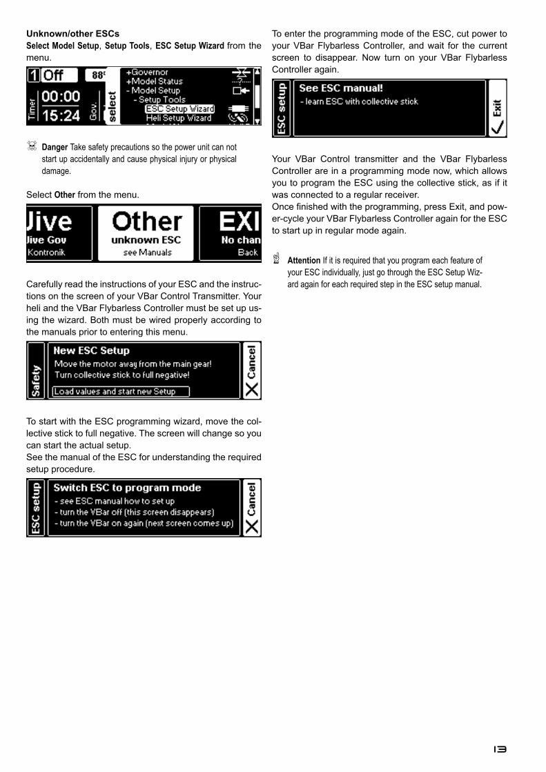
Unknown/other ESCsSelect Model Setup, Setup Tools, ESC Setup Wizard from the menu.
ľ Danger Take safety precautions so the power unit can not start up accidentally and cause physical injury or physical damage.
Select Other from the menu.
Carefully read the instructions of your ESC and the instruc-tions on the screen of your VBar Control Transmitter. Your heli and the VBar Flybarless Controller must be set up us-ing the wizard. Both must be wired properly according to the manuals prior to entering this menu.
To start with the ESC programming wizard, move the col-lective stick to full negative. The screen will change so you can start the actual setup.See the manual of the ESC for understanding the required setup procedure.
To enter the programming mode of the ESC, cut power to your VBar Flybarless Controller, and wait for the current screen to disappear. Now turn on your VBar Flybarless Controller again.
Your VBar Control transmitter and the VBar Flybarless Controller are in a programming mode now, which allows you to program the ESC using the collective stick, as if it was connected to a regular receiver.2QFH�¿QLVKHG�ZLWK�WKH�SURJUDPPLQJ��SUHVV�([LW��DQG�SRZ-er-cycle your VBar Flybarless Controller again for the ESC to start up in regular mode again.
Ļ Attention If it is required that you program each feature of your ESC individually, just go through the ESC Setup Wiz-ard again for each required step in the ESC setup manual.
14
General Settings
Express/Basic Setup
Ļ Attention All parameters explained here are banked, which means you can set different values for three different EDQNV�ÀLJKW�PRGHV��IRXU��LQ�FDVH�\RX�ZDQW�WR�XVH�EDQN�IRXU�for autorotation . To use this feature, install the Pro Parame-ters-App). The parameter for the active bank is highlighted in white. The highlighting changes immediately when you operate the switch assigned to bank switching.
Ļ Attention Once you enter a value (like ‘Mainrotor Expo’) and move one of the rotary knobs, the knob automatically assigns itself to the parameter in question. Note that the URWDU\�NQRE�SRVLWLRQ�LV�DEVROXWH��7KLV�PHDQV�LI�LW�LV�VHW�WR����IRU�D�VSHFL¿F�YDOXH��DQG�\RX�HQWHU�D�EDQN�ZKLFK�KDV�D�YDOXH�RI�����URWDWLQJ�WKH�NQRE�ZLOO�PDNH�WKH�SDUDPHWHU�MXPS�WR����¿UVW�� EHIRUH� LW� FKDQJHV� WR� WKH� VHOHFWHG� YDOXH�� 7KH� URWDU\�knob stays assigned until you turn off the transmitter or change the assignment, even if you exit the setup to the main screen.
Ļ Attention To avoid accidental changing of parameters, you may assign a switch to temporarily lock and unlock chang-ing parameters with the rotary knobs. Alternatively you may lock this feature completely (Transmitter Setup/Assign & Calibrate/Mandatory Switches).
Ļ Attention You may also change values with the EDS Dial. Note that the position of the EDS Dial is relative. This means it will always change parameters from where they are currently set. This feature is only active for the parame-ter currently selected from the menu.
Mainrotor Parameters
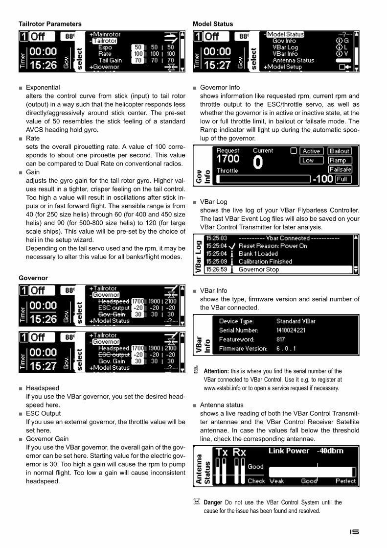
Ŷ� Exponentialalters the control curve from stick (input) to swash plate (output) in a way that it feels less direct/aggressive around center.
Ŷ� Styleaffects the overall response of the heli: Higher values result in a more precise feel (can be compared to a heli on a simulator), lower values result in a more vivid feel �FDQ�EH�FRPSDUHG�WR�WKH�IHHO�RI�D�À\EDUUHG�KHOL��
Ŷ� AgilityVHWV�WKH�RYHUDOO�UROO�DQG�ÀLS�UDWH�RI�WKH�PRGHO��,W�FDQ�EH�compared to Dual Rate on conventional radios. The VHQVLEOH�UDQJH�LV�IURP�����IRU�VFDOH�ÀLJKW��WKURXJK��������IRU�VSRUWV��DQG���'�À\LQJ�� WR������IRU�DJJUHVVLYH���'��ÀLJKW��
Ŷ� Gainadjusts the gyro gain for the aileron and elevator gyros. Higher values result in a tighter, crisper feeling on the cyclic controls. Too high a value will result in oscillations after stick inputs. The sensible range is from 40 (for 250 size helis) through 90 (for 500-800 size helis) to 120 (for large scale ships). This value will be pre-set by the choice of heli in the setup wizard.
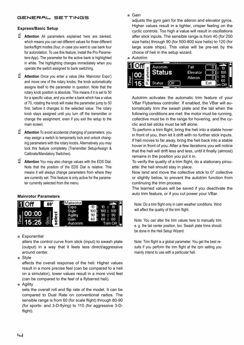
Ŷ� Autotrim
Autotrim activates the automatic trim feature of your VBar Flybarless controller. If enabled, the VBar will au-tomatically trim the swash plate and the tail when the following conditions are met: the motor must be running, collective must be in the range for hovering, and the cy-clic and tail sticks must be left alone.7R�SHUIRUP�D�WULP�ÀLJKW��EULQJ�WKH�KHOL�LQWR�D�VWDEOH�KRYHU�in front of you, then let it drift with no further stick inputs. If heli moves to far away, bring the heli back into a stable hover in front of you. After a few iterations you will notice WKDW�WKH�KHOL�ZLOO�GULIW�OHVV�DQG�OHVV��XQWLO�LW�¿QDOO\��DOPRVW��remains in the position you put it in.7R�YHULI\�WKH�TXDOLW\�RI�D�WULP�ÀLJKW��GR�D�VWDWLRQDU\�SLURX-ette: the heli should stay in place.Now land and move the collective stick to 0° collective or slightly below, to prevent the autotrim function from continuing the trim process. The learned values will be saved if you deactivate the auto trim feature, or if you cut power your VBar.
1RWH��'R�D�WULP�ÀLJKW�RQO\�LQ�FDOP�ZHDWKHU�FRQGLWLRQV��:LQG�ZLOO�DIIHFW�WKH�TXDOLW\�RI�WKH�WULP�ÀLJKW�
Note: You can alter the trim values here to manually trim e. g. the tail center position, too. Swash plate trims should be done in the Heli Setup Wizard.
1RWH��7ULP�ÀLJKW�LV�D�JOREDO�SDUDPHWHU��<RX�JHW�WKH�EHVW�UH-VXOWV� LI� \RX�SHUIRUP� WKH� WULP� ÀLJKW� DW� WKH� USP�VHWWLQJ� \RX�mainly intend to use with a particular heli.
15
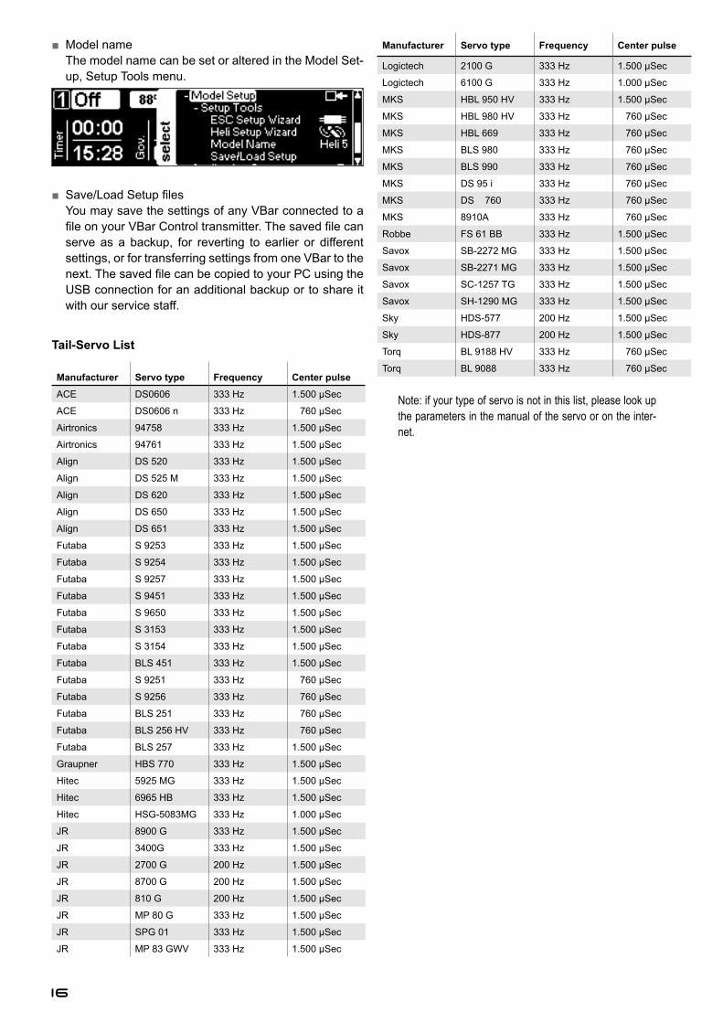
Tailrotor Parameters
Ŷ� Exponentialalters the control curve from stick (input) to tail rotor (output) in a way such that the helicopter responds less directly/aggressively around stick center. The pre-set value of 50 resembles the stick feeling of a standard AVCS heading hold gyro.
Ŷ� Ratesets the overall pirouetting rate. A value of 100 corre-sponds to about one pirouette per second. This value can be compared to Dual Rate on conventional radios.
Ŷ� Gainadjusts the gyro gain for the tail rotor gyro. Higher val-ues result in a tighter, crisper feeling on the tail control. Too high a value will result in oscillations after stick in-SXWV�RU�LQ�IDVW�IRUZDUG�ÀLJKW��7KH�VHQVLEOH�UDQJH�LV�IURP�40 (for 250 size helis) through 60 (for 400 and 450 size helis) and 90 (for 500-800 size helis) to 120 (for large scale ships). This value will be pre-set by the choice of heli in the setup wizard.Depending on the tail servo used and the rpm, it may be QHFHVVDU\�WR�DOWHU�WKLV�YDOXH�IRU�DOO�EDQNV�ÀLJKW�PRGHV�
Governor
Ŷ� HeadspeedIf you use the VBar governor, you set the desired head-speed here.
Ŷ� ESC OutputIf you use an external governor, the throttle value will be set here.
Ŷ� Governor GainIf you use the VBar governor, the overall gain of the gov-ernor can be set here. Starting value for the electric gov-ernor is 30. Too high a gain will cause the rpm to pump LQ�QRUPDO�ÀLJKW��7RR� ORZ�D�JDLQ�ZLOO�FDXVH� LQFRQVLVWHQW�headspeed.
Model Status
Ŷ� Governor Infoshows information like requested rpm, current rpm and throttle output to the ESC/throttle servo, as well as whether the governor is in active or inactive state, at the low or full throttle limit, in bailout or failsafe mode. The Ramp indicator will light up during the automatic spoo-lup of the governor.
Ŷ� VBar Logshows the live log of your VBar Flybarless Controller. 7KH�ODVW�9%DU�(YHQW�/RJ�¿OHV�ZLOO�DOVR�EH�VDYHG�RQ�\RXU�VBar Control Transmitter for later analysis.
Ŷ� VBar InfoVKRZV�WKH�W\SH��¿UPZDUH�YHUVLRQ�DQG�VHULDO�QXPEHU�RI�the VBar connected.
Ļ Attention: WKLV�LV�ZKHUH�\RX�¿QG�WKH�VHULDO�QXPEHU�RI�WKH�VBar connected to VBar Control. Use it e.g. to register at www.vstabi.info or to open a service request if necessary.
Ŷ� Antenna statusshows a live reading of both the VBar Control Transmit-ter antennae and the VBar Control Receiver Satellite antennae. In case the values fall below the threshold line, check the corresponding antennae.
ľ Danger Do not use the VBar Control System until the cause for the issue has been found and resolved.
16
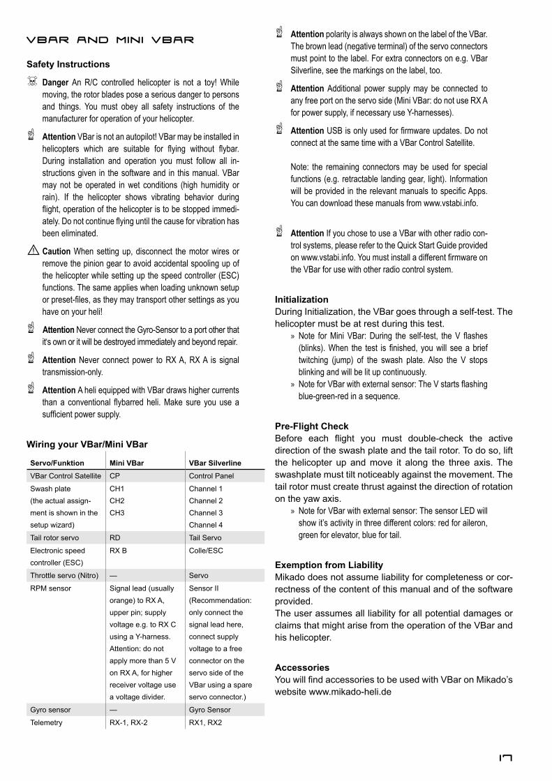
Ŷ� Model nameThe model name can be set or altered in the Model Set-up, Setup Tools menu.
Ŷ� 6DYH�/RDG�6HWXS�¿OHVYou may save the settings of any VBar connected to a ¿OH�RQ�\RXU�9%DU�&RQWURO�WUDQVPLWWHU��7KH�VDYHG�¿OH�FDQ�serve as a backup, for reverting to earlier or different settings, or for transferring settings from one VBar to the QH[W��7KH�VDYHG�¿OH�FDQ�EH�FRSLHG�WR�\RXU�3&�XVLQJ�WKH�USB connection for an additional backup or to share it with our service staff.
Tail-Servo List
0DQXIDFWXUHU Servo type Frequency Center pulseACE DS0606 333 Hz 1.500 µSec
ACE DS0606 n 333 Hz �����6HF
Airtronics 94758 333 Hz 1.500 µSec
Airtronics 94761 333 Hz 1.500 µSec
Align DS 520 333 Hz 1.500 µSec
Align DS 525 M 333 Hz 1.500 µSec
Align DS 620 333 Hz 1.500 µSec
Align DS 650 333 Hz 1.500 µSec
Align DS 651 333 Hz 1.500 µSec
Futaba S 9253 333 Hz 1.500 µSec
Futaba S 9254 333 Hz 1.500 µSec
Futaba S 9257 333 Hz 1.500 µSec
Futaba S 9451 333 Hz 1.500 µSec
Futaba S 9650 333 Hz 1.500 µSec
Futaba S 3153 333 Hz 1.500 µSec
Futaba S 3154 333 Hz 1.500 µSec
Futaba BLS 451 333 Hz 1.500 µSec
Futaba S 9251 333 Hz �����6HF
Futaba S 9256 333 Hz �����6HF
Futaba BLS 251 333 Hz �����6HF
Futaba BLS 256 HV 333 Hz �����6HF
Futaba BLS 257 333 Hz 1.500 µSec
Graupner HBS 770 333 Hz 1.500 µSec
Hitec 5925 MG 333 Hz 1.500 µSec
Hitec 6965 HB 333 Hz 1.500 µSec
Hitec HSG-5083MG 333 Hz 1.000 µSec
JR 8900 G 333 Hz 1.500 µSec
JR 3400G 333 Hz 1.500 µSec
JR 2700 G 200 Hz 1.500 µSec
JR 8700 G 200 Hz 1.500 µSec
JR 810 G 200 Hz 1.500 µSec
JR MP 80 G 333 Hz 1.500 µSec
JR SPG 01 333 Hz 1.500 µSec
JR MP 83 GWV 333 Hz 1.500 µSec
0DQXIDFWXUHU Servo type Frequency Center pulse
Logictech 2100 G 333 Hz 1.500 µSec
Logictech 6100 G 333 Hz 1.000 µSec
MKS HBL 950 HV 333 Hz 1.500 µSec
MKS HBL 980 HV 333 Hz �����6HF
MKS HBL 669 333 Hz �����6HF
MKS BLS 980 333 Hz �����6HF
MKS BLS 990 333 Hz �����6HF
MKS DS 95 i 333 Hz �����6HF
MKS '6���� 333 Hz �����6HF
MKS 8910A 333 Hz �����6HF
Robbe FS 61 BB 333 Hz 1.500 µSec
Savox SB-2272 MG 333 Hz 1.500 µSec
Savox SB-2271 MG 333 Hz 1.500 µSec
Savox SC-1257 TG 333 Hz 1.500 µSec
Savox SH-1290 MG 333 Hz 1.500 µSec
Sky HDS-577 200 Hz 1.500 µSec
Sky HDS-877 200 Hz 1.500 µSec
Torq BL 9188 HV 333 Hz �����6HF
Torq BL 9088 333 Hz �����6HF
Note: if your type of servo is not in this list, please look up the parameters in the manual of the servo or on the inter-net.
17
VBar and Mini VBar
6DIHW\�,QVWUXFWLRQV
ľ Danger An R/C controlled helicopter is not a toy! While moving, the rotor blades pose a serious danger to persons and things. You must obey all safety instructions of the manufacturer for operation of your helicopter.
Ļ Attention VBar is not an autopilot! VBar may be installed in KHOLFRSWHUV� ZKLFK� DUH� VXLWDEOH� IRU� À\LQJ� ZLWKRXW� À\EDU��During installation and operation you must follow all in-structions given in the software and in this manual. VBar may not be operated in wet conditions (high humidity or rain). If the helicopter shows vibrating behavior during ÀLJKW��RSHUDWLRQ�RI�WKH�KHOLFRSWHU�LV�WR�EH�VWRSSHG�LPPHGL-DWHO\��'R�QRW�FRQWLQXH�À\LQJ�XQWLO�WKH�FDXVH�IRU�YLEUDWLRQ�KDV�been eliminated.
Caution When setting up, disconnect the motor wires or remove the pinion gear to avoid accidental spooling up of the helicopter while setting up the speed controller (ESC) functions. The same applies when loading unknown setup RU�SUHVHW�¿OHV��DV�WKH\�PD\�WUDQVSRUW�RWKHU�VHWWLQJV�DV�\RX�have on your heli!
Ļ Attention 1HYHU�FRQQHFW�WKH�*\UR�6HQVRU�WR�D�SRUW�RWKHU�WKDW�it‘s own or it will be destroyed immediately and beyond repair.
Ļ Attention Never connect power to RX A, RX A is signal transmission-only.
Ļ Attention A heli equipped with VBar draws higher currents WKDQ� D� FRQYHQWLRQDO� À\EDUUHG� KHOL��0DNH� VXUH� \RX� XVH� D�VXI¿FLHQW�SRZHU�VXSSO\��
Wiring your VBar/Mini VBar
Servo/Funktion Mini VBar VBar SilverlineVBar Control Satellite CP Control Panel
Swash plate(the actual assign-ment is shown in the setup wizard)
CH1 CH2 CH3
Channel 1 Channel 2 Channel 3 Channel 4
Tail rotor servo RD Tail Servo
Electronic speed controller (ESC)
RX B Colle/ESC
Throttle servo (Nitro) — Servo
RPM sensor Signal lead (usually orange) to RX A, upper pin; supply voltage e.g. to RX C using a Y-harness.Attention: do not apply more than 5 V on RX A, for higher receiver voltage use a voltage divider.
Sensor II(Recommendation: only connect the signal lead here, connect supply voltage to a free connector on the servo side of the VBar using a spare servo connector.)
Gyro sensor — Gyro Sensor
Telemetry RX-1, RX-2 RX1, RX2
Ļ Attention polarity is always shown on the label of the VBar. The brown lead (negative terminal) of the servo connectors PXVW�SRLQW�WR�WKH�ODEHO��)RU�H[WUD�FRQQHFWRUV�RQ�H�J��9%DU�Silverline, see the markings on the label, too.
Ļ Attention Additional power supply may be connected to any free port on the servo side (Mini VBar: do not use RX A for power supply, if necessary use Y-harnesses).
Ļ Attention 86%�LV�RQO\�XVHG�IRU�¿UPZDUH�XSGDWHV��'R�QRW�connect at the same time with a VBar Control Satellite.
Note: the remaining connectors may be used for special functions (e.g. retractable landing gear, light). Information ZLOO�EH�SURYLGHG� LQ� WKH�UHOHYDQW�PDQXDOV�WR�VSHFL¿F�$SSV��You can download these manuals from www.vstabi.info.
Ļ Attention If you chose to use a VBar with other radio con-WURO�V\VWHPV��SOHDVH�UHIHU�WR�WKH�4XLFN�6WDUW�*XLGH�SURYLGHG�RQ�ZZZ�YVWDEL�LQIR��<RX�PXVW�LQVWDOO�D�GLIIHUHQW�¿UPZDUH�RQ�the VBar for use with other radio control system.
,QLWLDOL]DWLRQDuring Initialization, the VBar goes through a self-test. The helicopter must be at rest during this test.
» 1RWH� IRU�0LQL� 9%DU��'XULQJ� WKH� VHOI�WHVW�� WKH�9� ÀDVKHV��EOLQNV���:KHQ� WKH� WHVW� LV� ¿QLVKHG�� \RX�ZLOO� VHH�D�EULHI�twitching (jump) of the swash plate. Also the V stops blinking and will be lit up continuously.
» 1RWH�IRU�9%DU�ZLWK�H[WHUQDO�VHQVRU��7KH�9�VWDUWV�ÀDVKLQJ�blue-green-red in a sequence.
Pre-Flight Check%HIRUH� HDFK� ÀLJKW� \RX� PXVW� GRXEOH�FKHFN� WKH� DFWLYH� direction of the swash plate and the tail rotor. To do so, lift the helicopter up and move it along the three axis. The swashplate must tilt noticeably against the movement. The tail rotor must create thrust against the direction of rotation on the yaw axis.
» Note for VBar with external sensor: The sensor LED will show it’s activity in three different colors: red for aileron, green for elevator, blue for tail.
([HPSWLRQ�IURP�/LDELOLW\Mikado does not assume liability for completeness or cor-rectness of the content of this manual and of the software provided. The user assumes all liability for all potential damages or claims that might arise from the operation of the VBar and his helicopter.
Accessories<RX�ZLOO�¿QG�DFFHVVRULHV�WR�EH�XVHG�ZLWK�9%DU�RQ�0LNDGR¶V�website www.mikado-heli.de

18


