Setting up & Operating the HAKKO 936
16
Transcript of Setting up & Operating the HAKKO 936


2
Names of Parts
LED Heater Lamp
Temperature Control KnobKnob Mount
CAL Pot Plug/Calibrator
Hex Wrench
Power Switch
Iron Receptacle
Iron Holder Base
Small Cleaning Sponge
Large Cleaning Sponge
Cord Assembly
Setting up & Operating the HAKKO 936CAUTION
The sponge is compressed. It will swell when moistened with water. Before using the until, dampen the sponge with the water and squeeze it dry. Failure to do so may result in damage to the soldering tip.
A. Iron Holder1. Small Cleaning Sponge
Dampen the small cleaning sponge with water and then squeeze it dry. Place it in one of the 4 openings of the iron holder base.
2. Add water to approximately the level as shown. The small sponge will absorb water to keep the larger sponge above it wet at all times.*The large sponge may be used alone (w/o small sponge & water).
3. Dampen the large cleaning sponge and place it on the iron holder base.
Note: The iron receptacles for the 900 (S) and the 907/908 soldering irons are different.Be sure to use the proper one for each type of soldering iron. (Refer to Parts List.)
CAUTIONBe sure to turn off the power switch before connecting or disconnecting the soldering iron. Failure to do so may damage the P.W.B..
B. Connections1. Connect the cord assembly to the receptacle.2. Place the soldering iron in the iron holder.3. Plug the power cord into the power supply. Be sure to
ground the unit.C. Set the Temperature1. Set the temperature control knob to the desired
temperature.2. Lock the knob. The HAKKO 936 station is equipped with a tempe-
rature control knob lock. After setting the desired temperature, tighten the hex nut on the underside of the knob mount using the supplied hex wrench. Turn the nut clockwise to tighten the knob lock.
CAUTION• Donʼt over tighten the knob lock.• Donʼt attempt to turn the knob when the knob lock is on.
Turn clockwise firmly.
ReceptacleAlign the grooves and pins and push straight in.
English
Cord Assembly
13
1. 將手柄護套②從電線方向推移,鬆開栓緊發熱元件的螺絲①。
2. 向反時針方向扭開和取出螺帽③。
3. 取出焊鐵頭④。
4. 向著焊鐵頭方向,從手柄6拉出發熱元件⑤和電線。
測試終端板的傳感器和發熱元件的電阻值。此電阻值應與907
和908型一樣。
關於更換程序,請參閱更換部件的使用說明書。
1. 按開焊鐵電源,溫度設定為攝氏480度(華氏896度)。在
焊鐵電線的各個不同部位(包括鬆緊部位)搖動或纏結,
如果發熱器的液晶指示燈閃亮,則應更換電線。
注意:
雖然焊鐵電線正常,當溫度達到攝氏480度(華氏896
度)時,發熱器的液晶指示燈將會閃亮。
2. 測試焊鐵插頭腳和終端板電線之間的電阻值。
腳1-紅色 腳2-藍色 腳3-青色 腳4-白色 腳5-黑色
電阻值應為0歐姆,若大過0歐姆或∞,應更換電線。
請參閱更換部件的圖示。除去燒斷的保險絲,然後再焊接新
的保險絲。
2. 焊鐵電線破損測試焊鐵電線有以下兩個方法:
3. 更換保險絲
規格
電路圖
名稱 HAKKO 936
耗電 60瓦特
控制臺
936電焊臺/936電焊臺ESD
輸出電壓 交流電24伏特
溫度範圍 攝氏200-480度/華氏392-896度
外形體積 寬120x 高93x 深170毫米 / 4.7x3.7x6.7英寸
重量(不包括電線) 1,300克(2.9磅)
焊鐵頭溫度是以HAKKO 191溫度計測量。上述規格和設計可能變更,恕不另行奉告。
焊鐵
900S900S-ESD
907907-ESD
908908-ESD
耗電 交流電24伏特-50瓦特
焊鐵頭至接地電阻 低於2歐姆
焊鐵頭至接地電勢 低於2豪伏(標準為0.6豪伏)
發熱元件t 陶瓷發熱器
電線裝置 1.2米 (4英尺)
長度(無電線) 176毫米 (7英寸) 190毫米 (7.5英寸) 200毫米 (7.9英寸)
重量(無電線) 25克 (0.061磅) 44克 (0.09磅) 554克 (0.12磅)
變壓器
3蕊電線
接地
印刷電路板
中
文

12
如何檢查發熱元件和組裝電線破損
拔出插頭,測試連接插頭的腳與腳之
間的電阻值如下:
如果“a”與“b”之間的電阻值有異
於上表電阻值,需更換發熱元件(傳
感器)和/或電線。請按照程序1和2進
行。如果“c”電阻值大於上表電阻
值,則要用砂紙或鋼絨輕輕擦除下圖
所示部位的氧化層。
a. 第4腳與第5腳之間(發熱元件) 2.5-3.5歐姆(正常)
b. 第1腳與第2腳之間(傳感器) 43-58歐姆(正常)
c. 第3腳與焊鐵頭之間 2歐姆以下
1. 發熱元件破損 如何拆開907/908型焊鐵
發熱元件(紅色) 傳感器(藍色)
1. 向反時針方向扭開螺帽①,取出焊鐵頭護套②和焊鐵頭
③。
2. 向反時針方向扭開套頭④,從焊鐵中拉出套頭。
3. 從手柄⑫中取出發熱元件⑥和電線⑪(向著焊鐵頭方向
拉出)。
4. 從D形套中拉出接地彈簧⑤。
當發熱元件回復到室溫時測量:
1. 發熱元件電阻值(紅色)2.5-3.5歐姆
2. 傳感器電阻值(藍色)43-58歐姆
如果電阻值反常,更換發熱元件。
關於更換程序,請參閱更換部件內的說明書。
更換發熱元件後,請進行以下事項。
1. 測量第4腳和第1或第2腳之間,第5腳和第1或第2腳之間
電阻值。如果不是∞,則是發熱元件和傳感器受觸及,
這將會損壞印刷電路板。
2. 測量“a”“b”“c”電阻值以確定引線未被扭曲,而接
地彈簧也連接妥當。
如何拆開900S型焊鐵
中
文
3
Tip Care and Use
D. Turn on the Power Switch.The heater lamp blinks on and off when the tip temperature reaches the set temperature. The unit is now ready to perform soldering work.For greater convenience, and soldering efficiency, two stations can be securely stacked as shown.
CAUTIONThe soldering iron must be placed in the iron holder when not in use.
Tip Temperature ----------
Cleaning ---------------------
When Not in Use ----------
After Use --------------------
High soldering temperatures can degrade the tip.Use the lowest possible soldering temperature.The excellent thermal recovery characteristics ensure efficient and effective soldering even at low temperatures.This also protects the soldered items from thermal damage.Clean the tip regularly with a cleaning sponge, as oxides and carbides from the solder and flux can form impurities on the tip.These impurities can result in defective joints or reduce the tipʼs heat conductivity.When using the soldering iron continuously, be sure to loosen the tip and remove all oxides at least once a week.This helps prevent seizure and reduction of the tip temperature.Never leave the soldering iron sitting at high temperature for long periods of time, as the tipʼs solder plating will become covered with oxide, which can greatly reduce the tipʼs heat conductivity.Wipe the tip clean and coat the tip with fresh solder.This helps prevent tip oxidation.
MaintenanceInspect and Clean the Tip
CAUTIONNever file the Tip to remove oxide.
1. Set the temperature to 250°C (482°F).2. When the temperature stabilizes, clean the tip with the
cleaning sponge and check the condition of the tip.3. If there is black oxide on the solder-plated portion of the
tip, apply new solder (containing flux) and wipe the tip on the cleaning sponge. Repeat until the oxide is completely removed. Coat with new solder.
4. If the tip is deformed or heavily eroded, replace it with a new one.
Calibrating the Iron TemperatureThe soldering iron should be recalibrated after changing the iron, or replacing the heating element or tip.
1) Connect the cord assembly plug to the receptacle on the station.
2) Set the temperature control knob to 400°C (750°F).3) Turn the power switch to ʻONʼ and wait until the temperature
stabilizes. Remove the CAL pot plug.4) When the temperature stabilizes, use a straight-edge (-)
screwdriver or small plus (+) screwdriver to adjust the screw (market CAL at the station) until the tip thermometer indicates a temperature of 400°C (750°F). Turn the screw clockwise to increase the temperature and counterclockwise to reduce the temperature. Replace the CAL pot plug.
* We recommend the HAKKO 191/192 thermometer for measuring the tip temperature.
Engl
ish
4
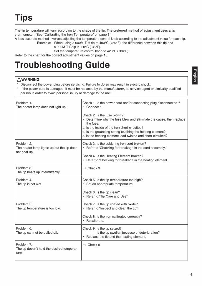
Tips The tip temperature will vary according to the shape of the tip. The preferred method of adjustment uses a tip thermometer. (See “Calibrating the Iron Temperature” on page 3.)A less accurate method involves adjusting the temperature control knob according to the adjustment value for each tip.
Example: When using a 900M-T-H tip at 400°C (750°F), the difference between this tip and a 900M-T-B tip is -20°C (-36°F). Set the temperature control knob to 420°C (786°F).
Refer to the chart for the correct adjustment values on page 15.
Troubleshooting Guide WARNING
* Disconnect the power plug before servicing. Failure to do so may result in electric shock.* If the power cord is damaged, it must be replaced by the manufacturer, its service agent or similarity qualified
person in order to avoid personal injury or damage to the unit.
Problem 1.The heater lamp does not light up.
Check 1. Is the power cord and/or connecting plug disconnected ?• Connect it.
Check 2. Is the fuse blown?• Determine why the fuse blew and eliminate the cause, then replace
the fuse.a. Is the inside of the iron short-circuited?b. Is the grounding spring touching the heating element?c. Is the heating element lead twisted and short-circuited?
Problem 2.The heater lamp lights up but the tip does not heat up.
Check 3. Is the soldering iron cord broken?• Refer to ʻChecking for breakage in the cord assembly.ʼ
Check 4. Is the Heating Element broken?• Refer to ʻChecking for breakage in the heating element.
Problem 3.The tip heats up intermittently.
→ Check 3
Problem 4.The tip is not wet.
Check 5. Is the tip temperature too high?• Set an appropriate temperature.
Check 6. Is the tip clean?• Refer to “Tip Care and Use”.
Problem 5.The tip temperature is too low.
Check 7. Is the tip coated with oxide?• Refer to “Inspect and clean the tip”.
Check 8. Is the iron calibrated correctly?• Recalibrate.
Problem 6.The tip can not be pulled off.
Check 9. Is the tip seized? Is the tip swollen because of deterioration?• Replace the tip and the heating element.
Problem 7.The tip doesnʼt hold the desired tempera-ture.
→ Check 8
English
11
故障1: 發熱器指示燈不亮。 檢查1. 電線或連接插頭是否鬆脫?
重新接妥
檢查2. 保險絲是否燒斷?
確定保險絲燒斷原因後進行修理,並更換新保險絲。
a.焊鐵內部是否短路?
b.接地彈簧是否觸及發熱元件?
c.發熱元件引線是否扭曲和短路?
故障2: 發熱器指示燈雖亮,但焊鐵頭
不昇溫。
檢查3. 焊鐵電線是否破損?
請參閱“組裝電線破損檢查法”。
檢查4.發熱元件是否破損
請參閱“發熱元件破損檢查法”。
故障3: 焊鐵頭斷斷續續地昇溫時。 →檢查3.
故障4: 焊鐵頭霑不上銲錫。 檢查5. 焊鐵頭溫度是否過高?
重新設定適當溫度。
檢查6. 焊鐵頭是否清理乾淨?
請參閱“焊鐵頭維護和使用”。
故障5: 焊鐵頭溫度太低。 檢查7. 焊鐵頭是否衍生氧化物?
請參閱“檢查和清理焊鐵頭”。
檢查8. 焊鐵是否正確校準?
重新校準。
故障6: 焊鐵頭拆不開。 檢查9. 焊鐵頭是否被緊夾?焊鐵頭是否因鏽污而膨脹?
更換新的焊鐵頭及發熱元件。
故障7: 焊鐵頭未昇溫達所需溫度。 →檢查8.
焊鐵頭
不同款型焊鐵頭的溫度可能有所不同。調節的最理想方法是使用測量焊鐵頭溫度計。(參照第10頁
“校準焊鐵頭溫度”)
除了以上的調節方法外,也可以採用下述方法調節。
利用控溫旋鈕按照各款型焊鐵頭溫度調節。
例如: 當使用900M-T-H型溫度在於攝氏400度(華氏750度)時,與900M-T-B型焊鐵頭
相差20度。因此必須調節控溫旋鈕為攝氏420度(華氏786度)。
請參閱(第15頁正確)溫度調節表:
排除故障指南
警告:
*進行維修之前應關掉電源,否則可能發生觸電事故。
*若電線損壞,應請廠家或其維修服務代理商或類似之合格人士修理,以免發生傷害身體或損壞電
焊臺。
中
文

10
焊鐵頭的維護和使用
D. 按開開關掣當焊鐵頭升溫至所設定溫度時,發熱器指示燈
即會閃亮,指示可以進行焊接工作。
為了更方便工作和取得更高焊接效率,可以將
兩臺電焊臺重疊如圖示。
注意:
當不使用時,應將焊鐵放置在焊鐵架上。
焊鐵頭溫度 ----------
清理 ---------------------
當不使用時 ----------
使用後 ------------------
溫度過高會減弱焊鐵頭功能,因此應選擇盡可能低之溫度。此焊鐵頭的
溫度回復力優良,較低的溫度也可充分的焊接,可保護對於溫度敏感之
元件。
應定期使用清潔海綿清理焊鐵頭。焊接後,焊鐵頭的殘餘焊劑所衍生的
氧化物和碳化物會損害焊鐵頭,造成焊接差誤,或者使焊鐵頭導熱功能
減退。
長時間連續使用焊鐵時,應每周一次拆開焊鐵頭清除氧化物,防止焊鐵
頭受損而減低溫度。
不使用焊鐵時,不可讓焊鐵長時間處在高溫狀態,會使焊鐵頭上的焊劑
轉化為氧化物,致使焊鐵頭導熱功能大為減退。
使用後,應抹淨焊鐵頭,鍍上新錫層,以防止焊鐵頭引起氧化作用。
保養檢查和清理焊鐵頭
注意:
切勿用銼刀剔除焊鐵頭上的氧化物。
1. 設定溫度為攝氏250度(華氏482度)。
2. 溫度穩定後,以清潔海綿清理焊鐵頭,並檢查焊鐵
頭狀況。
3. 如果焊鐵頭的鍍錫部份含有黑色氧化物,可鍍上新
錫層,再用清潔海綿抹淨焊鐵頭。如此重複清理,
直到徹底除去氧化物為止,然後再鍍上新錫層。
4. 如果焊鐵頭變形或衍生重秀鏽,必須替換新的。
校準焊鐵溫度每當更換焊鐵,或替換發熱器、焊鐵頭
後,應重新校準焊鐵溫度。1. 將電線裝置的插頭插入電焊臺插座。
2. 控溫旋鈕攝定為攝氏400度(華氏750度)。
3. 按開電源,等待溫度穩定後,移去校準計筒狀插
頭。
4. 溫度穩定後,以“-”字或小“+”字螺絲起子旋轉螺
絲(電焊臺誌有CAL字樣的螺絲),直到溫度計顯示
攝氏400度(華氏750度)為止。順時針方向旋轉是昇
溫,反時針方向是降溫。接上校準計CAL筒狀插頭。
*我廠建議您採用HAKKO 191/192溫度計測試焊鐵頭溫度。
中
文
5
Checking for breakage of the heating element and cord assemblyDisconnect the plug and measure the resistance value between the connecting plug pins as follows.If the values of ʻaʼ and ʻbʼ are outside the above value, replace the heating element (sensor) and /or cord assembly. Refer to Procedures 1 and 2.If the value of ʻcʼ is over the above value, remove the oxidization film by lightly rubbing with sand-paper or steel wool the point as shown.
a. Between pins 4 & 5 (Heating Element) 2.5 – 3.5 Ω (Normal)b. Between pins 1 & 2 (Sensor) 43 – 58 Ω (Normal)c. Between pins 3 & Tip Under 2 Ω
1. Broken Heating Element Disassembling the 907/908
Heating Element (Red) Sensor (Blue)
1. Turn the nut (1) counterclockwise and remove the tip enclosure (2), the tip (3).
2. Turn the nipple (4) counterclockwise and remove it from the iron.
3. Pull both the heating element (6) and the cord assembly (11) out of the handle (12). (Toward the tip of the iron.)
4. Pull the grounding spring (5) out of the D-sleeve.
Measure when the heating element is at room temperature.1. Resistance value of heating element (RED) 2.5 – 3.5 Ω2. Resistance value of sensor (BLUE) 43 – 58 Ω
If the resistance value is not normal, replace the heating element.(Refer to the instructions included with the replacement part.)
After replacing the heating element.1. Measure the resistance value between 1) pins 4 & 1 or 2 2)
pins 5 & 1 or 2. If it is not ∞, the heating element and sensor are touching. This will damage the P.W.B.
2. Measure the resistance value ʻaʼ, ʻbʼ, and ʻcʼ to confirm that the leads are not twisted and that the grounding spring is properly connected.
Disassembling the 900S
Engl
ish

6
1. Slide the handle cover (2) toward the cord and remove the screw (1)
securing the heating element.2. Turn the nut (3) counterclockwise and remove it.3. Remove the tip (4).4. Pull both the heating element (5) and the cord toward the tip of the
iron and out of the handle (6).Measure the resistance values at the sensor and the heating element of the terminal board.The resistance value should be the same as for the 907, 908.To replace the heating element, refer to the instructions included with the replacement part.1. Turn the unit ON and set the temperature control knob to 480°C (896
°F). Then wiggle and kink the iron cord at various locations along its length, including in the strain relief area.If the LED heater lamp flickers, then the cord needs to be replaced.
CAUTIONThe LED heater lamp will flicker even with a normal Iron cord if the temperature reaches 480°C (896°F).
2. Check the resistance between the pin of the plug and the wire on the terminal.Pin 1: Red Pin 2: Blue Pin 3: Green Pin 4: White Pin 5: BlackThe value should be 0 Ω. If it is greater than 0 Ω or is ∞, the cord should be replaced.
Refer to the drawing in the replacement parts section of this manual. Desolder the blown fuse and remove it. Solder on a new one.
2. Broken Soldering Iron CordThere are two methods of testing the soldering iron cord.
3. Replacing the Fuse
Specifications
Wiring Diagram
Name HAKKO 936Power Consumption 60W
Station936 Station / 936 Station ESD
Output Voltage 24V ACTemperature Range 200°C - 480°C / 392°F - 896°FDimensions 120(W) x 938H)x70(D) mm /
4.7(W)x3.7(H)x6.7(D) in.Weight (W/O Cord) 1300 g (2.9 lbs.)
• The tip temperature was measured using HAKKO 191 thermometer.• Specifications and design subject to change without notice.
Soldering Iron900S900S-ESD
907907-ESD
908908-ESD
Power Consumption 24V AC - 50WTip to Ground Resistance Under 2 ΩTip to Ground Potential Under 2 mV (TYP. 0.6 mV)Heating Element Ceramic heaterCord Assembly 1.2 m (4 ft.)Total Length (w/o Cord) 176 mm (7 in.) 190 mm (7.5 in.) 200 mm (7.9 in.)Weight (w/o Cord) 25 g (0.06 lbs.) 44 g (0.09 lbs.) 54 g (0.12 lbs.)
Transformer
3-core
Ground
P.W.B.
English
9
部件名稱
液晶顯示發熱器指示燈
控溫旋鈕
旋鈕架
校準計筒狀插頭/校準計
六角頭扳手
電線
電源開關
焊鐵插座
焊鐵架基座
小塊清潔海綿
大塊清潔海綿
電線
裝置和使用HAKKO 936注意:
海綿是可擠壓物體,水濕則漲大。使用海綿時,先濕水再擠乾。否則會損壞焊鐵頭。
A. 焊鐵架1. 小塊清潔海綿
將小塊清潔海綿先濕水再擠乾,置入焊鐵架底
座四個凹洞之一。
2. 添水至圖1所示水平面。小塊海綿吸收水分後,
可使置於其上的大塊海綿一直保持潮濕狀態。*
也可以單用大塊海綿(省去小塊海綿和添水)。
3. 然後霑濕大塊海綿,置於焊鐵架底座。
註: 900S型和907/908型焊鐵架有所不同。更換焊鐵
時,應選用適當款型。請參照“部件清單”。
注意:
進行連接和解開焊鐵時,切記要關掉電源,以免損壞印刷電路板。
B. 連接1. 將電線裝置連接焊鐵插座。
2. 將焊鐵置放於焊鐵架。
3. 將插頭插入電源插座。切記要接地。
C. 設定溫度1. 將控溫旋鈕設定在所需溫度點。
2.. 鎖定控溫旋鈕。
HAKKO 936配有溫度調節鈕鎖。當設定所需溫
度後,以所供應的六角頭扳手栓緊鈕座旁邊的
六角螺帽。依順時針方向栓緊鈕鎖。
注意:
切勿過度栓緊鈕座。
當上鎖後,切勿扭開鈕鎖。
按順時針方向擰緊。
插座
對準定位然後插入。
中
文

10
焊鐵頭的維護和使用
D. 按開開關掣當焊鐵頭升溫至所設定溫度時,發熱器指示燈
即會閃亮,指示可以進行焊接工作。
為了更方便工作和取得更高焊接效率,可以將
兩臺電焊臺重疊如圖示。
注意:
當不使用時,應將焊鐵放置在焊鐵架上。
焊鐵頭溫度 ----------
清理 ---------------------
當不使用時 ----------
使用後 ------------------
溫度過高會減弱焊鐵頭功能,因此應選擇盡可能低之溫度。此焊鐵頭的
溫度回復力優良,較低的溫度也可充分的焊接,可保護對於溫度敏感之
元件。
應定期使用清潔海綿清理焊鐵頭。焊接後,焊鐵頭的殘餘焊劑所衍生的
氧化物和碳化物會損害焊鐵頭,造成焊接差誤,或者使焊鐵頭導熱功能
減退。
長時間連續使用焊鐵時,應每周一次拆開焊鐵頭清除氧化物,防止焊鐵
頭受損而減低溫度。
不使用焊鐵時,不可讓焊鐵長時間處在高溫狀態,會使焊鐵頭上的焊劑
轉化為氧化物,致使焊鐵頭導熱功能大為減退。
使用後,應抹淨焊鐵頭,鍍上新錫層,以防止焊鐵頭引起氧化作用。
保養檢查和清理焊鐵頭
注意:
切勿用銼刀剔除焊鐵頭上的氧化物。
1. 設定溫度為攝氏250度(華氏482度)。
2. 溫度穩定後,以清潔海綿清理焊鐵頭,並檢查焊鐵
頭狀況。
3. 如果焊鐵頭的鍍錫部份含有黑色氧化物,可鍍上新
錫層,再用清潔海綿抹淨焊鐵頭。如此重複清理,
直到徹底除去氧化物為止,然後再鍍上新錫層。
4. 如果焊鐵頭變形或衍生重秀鏽,必須替換新的。
校準焊鐵溫度每當更換焊鐵,或替換發熱器、焊鐵頭
後,應重新校準焊鐵溫度。1. 將電線裝置的插頭插入電焊臺插座。
2. 控溫旋鈕攝定為攝氏400度(華氏750度)。
3. 按開電源,等待溫度穩定後,移去校準計筒狀插
頭。
4. 溫度穩定後,以“-”字或小“+”字螺絲起子旋轉螺
絲(電焊臺誌有CAL字樣的螺絲),直到溫度計顯示
攝氏400度(華氏750度)為止。順時針方向旋轉是昇
溫,反時針方向是降溫。接上校準計CAL筒狀插頭。
*我廠建議您採用HAKKO 191/192溫度計測試焊鐵頭溫度。
中
文
5
Checking for breakage of the heating element and cord assemblyDisconnect the plug and measure the resistance value between the connecting plug pins as follows.If the values of ʻaʼ and ʻbʼ are outside the above value, replace the heating element (sensor) and /or cord assembly. Refer to Procedures 1 and 2.If the value of ʻcʼ is over the above value, remove the oxidization film by lightly rubbing with sand-paper or steel wool the point as shown.
a. Between pins 4 & 5 (Heating Element) 2.5 – 3.5 Ω (Normal)b. Between pins 1 & 2 (Sensor) 43 – 58 Ω (Normal)c. Between pins 3 & Tip Under 2 Ω
1. Broken Heating Element Disassembling the 907/908
Heating Element (Red) Sensor (Blue)
1. Turn the nut (1) counterclockwise and remove the tip enclosure (2), the tip (3).
2. Turn the nipple (4) counterclockwise and remove it from the iron.
3. Pull both the heating element (6) and the cord assembly (11) out of the handle (12). (Toward the tip of the iron.)
4. Pull the grounding spring (5) out of the D-sleeve.
Measure when the heating element is at room temperature.1. Resistance value of heating element (RED) 2.5 – 3.5 Ω2. Resistance value of sensor (BLUE) 43 – 58 Ω
If the resistance value is not normal, replace the heating element.(Refer to the instructions included with the replacement part.)
After replacing the heating element.1. Measure the resistance value between 1) pins 4 & 1 or 2 2)
pins 5 & 1 or 2. If it is not ∞, the heating element and sensor are touching. This will damage the P.W.B.
2. Measure the resistance value ʻaʼ, ʻbʼ, and ʻcʼ to confirm that the leads are not twisted and that the grounding spring is properly connected.
Disassembling the 900S
Engl
ish

4
Tips The tip temperature will vary according to the shape of the tip. The preferred method of adjustment uses a tip thermometer. (See “Calibrating the Iron Temperature” on page 3.)A less accurate method involves adjusting the temperature control knob according to the adjustment value for each tip.
Example: When using a 900M-T-H tip at 400°C (750°F), the difference between this tip and a 900M-T-B tip is -20°C (-36°F). Set the temperature control knob to 420°C (786°F).
Refer to the chart for the correct adjustment values on page 15.
Troubleshooting Guide WARNING
* Disconnect the power plug before servicing. Failure to do so may result in electric shock.* If the power cord is damaged, it must be replaced by the manufacturer, its service agent or similarity qualified
person in order to avoid personal injury or damage to the unit.
Problem 1.The heater lamp does not light up.
Check 1. Is the power cord and/or connecting plug disconnected ?• Connect it.
Check 2. Is the fuse blown?• Determine why the fuse blew and eliminate the cause, then replace
the fuse.a. Is the inside of the iron short-circuited?b. Is the grounding spring touching the heating element?c. Is the heating element lead twisted and short-circuited?
Problem 2.The heater lamp lights up but the tip does not heat up.
Check 3. Is the soldering iron cord broken?• Refer to ʻChecking for breakage in the cord assembly.ʼ
Check 4. Is the Heating Element broken?• Refer to ʻChecking for breakage in the heating element.
Problem 3.The tip heats up intermittently.
→ Check 3
Problem 4.The tip is not wet.
Check 5. Is the tip temperature too high?• Set an appropriate temperature.
Check 6. Is the tip clean?• Refer to “Tip Care and Use”.
Problem 5.The tip temperature is too low.
Check 7. Is the tip coated with oxide?• Refer to “Inspect and clean the tip”.
Check 8. Is the iron calibrated correctly?• Recalibrate.
Problem 6.The tip can not be pulled off.
Check 9. Is the tip seized? Is the tip swollen because of deterioration?• Replace the tip and the heating element.
Problem 7.The tip doesnʼt hold the desired tempera-ture.
→ Check 8
English
11
故障1: 發熱器指示燈不亮。 檢查1. 電線或連接插頭是否鬆脫?
重新接妥
檢查2. 保險絲是否燒斷?
確定保險絲燒斷原因後進行修理,並更換新保險絲。
a.焊鐵內部是否短路?
b.接地彈簧是否觸及發熱元件?
c.發熱元件引線是否扭曲和短路?
故障2: 發熱器指示燈雖亮,但焊鐵頭
不昇溫。
檢查3. 焊鐵電線是否破損?
請參閱“組裝電線破損檢查法”。
檢查4.發熱元件是否破損
請參閱“發熱元件破損檢查法”。
故障3: 焊鐵頭斷斷續續地昇溫時。 →檢查3.
故障4: 焊鐵頭霑不上銲錫。 檢查5. 焊鐵頭溫度是否過高?
重新設定適當溫度。
檢查6. 焊鐵頭是否清理乾淨?
請參閱“焊鐵頭維護和使用”。
故障5: 焊鐵頭溫度太低。 檢查7. 焊鐵頭是否衍生氧化物?
請參閱“檢查和清理焊鐵頭”。
檢查8. 焊鐵是否正確校準?
重新校準。
故障6: 焊鐵頭拆不開。 檢查9. 焊鐵頭是否被緊夾?焊鐵頭是否因鏽污而膨脹?
更換新的焊鐵頭及發熱元件。
故障7: 焊鐵頭未昇溫達所需溫度。 →檢查8.
焊鐵頭
不同款型焊鐵頭的溫度可能有所不同。調節的最理想方法是使用測量焊鐵頭溫度計。(參照第10頁
“校準焊鐵頭溫度”)
除了以上的調節方法外,也可以採用下述方法調節。
利用控溫旋鈕按照各款型焊鐵頭溫度調節。
例如: 當使用900M-T-H型溫度在於攝氏400度(華氏750度)時,與900M-T-B型焊鐵頭
相差20度。因此必須調節控溫旋鈕為攝氏420度(華氏786度)。
請參閱(第15頁正確)溫度調節表:
排除故障指南
警告:
*進行維修之前應關掉電源,否則可能發生觸電事故。
*若電線損壞,應請廠家或其維修服務代理商或類似之合格人士修理,以免發生傷害身體或損壞電
焊臺。
中
文

12
如何檢查發熱元件和組裝電線破損
拔出插頭,測試連接插頭的腳與腳之
間的電阻值如下:
如果“a”與“b”之間的電阻值有異
於上表電阻值,需更換發熱元件(傳
感器)和/或電線。請按照程序1和2進
行。如果“c”電阻值大於上表電阻
值,則要用砂紙或鋼絨輕輕擦除下圖
所示部位的氧化層。
a. 第4腳與第5腳之間(發熱元件) 2.5-3.5歐姆(正常)
b. 第1腳與第2腳之間(傳感器) 43-58歐姆(正常)
c. 第3腳與焊鐵頭之間 2歐姆以下
1. 發熱元件破損 如何拆開907/908型焊鐵
發熱元件(紅色) 傳感器(藍色)
1. 向反時針方向扭開螺帽①,取出焊鐵頭護套②和焊鐵頭
③。
2. 向反時針方向扭開套頭④,從焊鐵中拉出套頭。
3. 從手柄⑫中取出發熱元件⑥和電線⑪(向著焊鐵頭方向
拉出)。
4. 從D形套中拉出接地彈簧⑤。
當發熱元件回復到室溫時測量:
1. 發熱元件電阻值(紅色)2.5-3.5歐姆
2. 傳感器電阻值(藍色)43-58歐姆
如果電阻值反常,更換發熱元件。
關於更換程序,請參閱更換部件內的說明書。
更換發熱元件後,請進行以下事項。
1. 測量第4腳和第1或第2腳之間,第5腳和第1或第2腳之間
電阻值。如果不是∞,則是發熱元件和傳感器受觸及,
這將會損壞印刷電路板。
2. 測量“a”“b”“c”電阻值以確定引線未被扭曲,而接
地彈簧也連接妥當。
如何拆開900S型焊鐵
中
文
3
Tip Care and Use
D. Turn on the Power Switch.The heater lamp blinks on and off when the tip temperature reaches the set temperature. The unit is now ready to perform soldering work.For greater convenience, and soldering efficiency, two stations can be securely stacked as shown.
CAUTIONThe soldering iron must be placed in the iron holder when not in use.
Tip Temperature ----------
Cleaning ---------------------
When Not in Use ----------
After Use --------------------
High soldering temperatures can degrade the tip.Use the lowest possible soldering temperature.The excellent thermal recovery characteristics ensure efficient and effective soldering even at low temperatures.This also protects the soldered items from thermal damage.Clean the tip regularly with a cleaning sponge, as oxides and carbides from the solder and flux can form impurities on the tip.These impurities can result in defective joints or reduce the tipʼs heat conductivity.When using the soldering iron continuously, be sure to loosen the tip and remove all oxides at least once a week.This helps prevent seizure and reduction of the tip temperature.Never leave the soldering iron sitting at high temperature for long periods of time, as the tipʼs solder plating will become covered with oxide, which can greatly reduce the tipʼs heat conductivity.Wipe the tip clean and coat the tip with fresh solder.This helps prevent tip oxidation.
MaintenanceInspect and Clean the Tip
CAUTIONNever file the Tip to remove oxide.
1. Set the temperature to 250°C (482°F).2. When the temperature stabilizes, clean the tip with the
cleaning sponge and check the condition of the tip.3. If there is black oxide on the solder-plated portion of the
tip, apply new solder (containing flux) and wipe the tip on the cleaning sponge. Repeat until the oxide is completely removed. Coat with new solder.
4. If the tip is deformed or heavily eroded, replace it with a new one.
Calibrating the Iron TemperatureThe soldering iron should be recalibrated after changing the iron, or replacing the heating element or tip.
1) Connect the cord assembly plug to the receptacle on the station.
2) Set the temperature control knob to 400°C (750°F).3) Turn the power switch to ʻONʼ and wait until the temperature
stabilizes. Remove the CAL pot plug.4) When the temperature stabilizes, use a straight-edge (-)
screwdriver or small plus (+) screwdriver to adjust the screw (market CAL at the station) until the tip thermometer indicates a temperature of 400°C (750°F). Turn the screw clockwise to increase the temperature and counterclockwise to reduce the temperature. Replace the CAL pot plug.
* We recommend the HAKKO 191/192 thermometer for measuring the tip temperature.
Engl
ish

2
Names of Parts
LED Heater Lamp
Temperature Control KnobKnob Mount
CAL Pot Plug/Calibrator
Hex Wrench
Power Switch
Iron Receptacle
Iron Holder Base
Small Cleaning Sponge
Large Cleaning Sponge
Cord Assembly
Setting up & Operating the HAKKO 936CAUTION
The sponge is compressed. It will swell when moistened with water. Before using the until, dampen the sponge with the water and squeeze it dry. Failure to do so may result in damage to the soldering tip.
A. Iron Holder1. Small Cleaning Sponge
Dampen the small cleaning sponge with water and then squeeze it dry. Place it in one of the 4 openings of the iron holder base.
2. Add water to approximately the level as shown. The small sponge will absorb water to keep the larger sponge above it wet at all times.*The large sponge may be used alone (w/o small sponge & water).
3. Dampen the large cleaning sponge and place it on the iron holder base.
Note: The iron receptacles for the 900 (S) and the 907/908 soldering irons are different.Be sure to use the proper one for each type of soldering iron. (Refer to Parts List.)
CAUTIONBe sure to turn off the power switch before connecting or disconnecting the soldering iron. Failure to do so may damage the P.W.B..
B. Connections1. Connect the cord assembly to the receptacle.2. Place the soldering iron in the iron holder.3. Plug the power cord into the power supply. Be sure to
ground the unit.C. Set the Temperature1. Set the temperature control knob to the desired
temperature.2. Lock the knob. The HAKKO 936 station is equipped with a tempe-
rature control knob lock. After setting the desired temperature, tighten the hex nut on the underside of the knob mount using the supplied hex wrench. Turn the nut clockwise to tighten the knob lock.
CAUTION• Donʼt over tighten the knob lock.• Donʼt attempt to turn the knob when the knob lock is on.
Turn clockwise firmly.
ReceptacleAlign the grooves and pins and push straight in.
English
Cord Assembly
13
1. 將手柄護套②從電線方向推移,鬆開栓緊發熱元件的螺絲①。
2. 向反時針方向扭開和取出螺帽③。
3. 取出焊鐵頭④。
4. 向著焊鐵頭方向,從手柄6拉出發熱元件⑤和電線。
測試終端板的傳感器和發熱元件的電阻值。此電阻值應與907
和908型一樣。
關於更換程序,請參閱更換部件的使用說明書。
1. 按開焊鐵電源,溫度設定為攝氏480度(華氏896度)。在
焊鐵電線的各個不同部位(包括鬆緊部位)搖動或纏結,
如果發熱器的液晶指示燈閃亮,則應更換電線。
注意:
雖然焊鐵電線正常,當溫度達到攝氏480度(華氏896
度)時,發熱器的液晶指示燈將會閃亮。
2. 測試焊鐵插頭腳和終端板電線之間的電阻值。
腳1-紅色 腳2-藍色 腳3-青色 腳4-白色 腳5-黑色
電阻值應為0歐姆,若大過0歐姆或∞,應更換電線。
請參閱更換部件的圖示。除去燒斷的保險絲,然後再焊接新
的保險絲。
2. 焊鐵電線破損測試焊鐵電線有以下兩個方法:
3. 更換保險絲
規格
電路圖
名稱 HAKKO 936
耗電 60瓦特
控制臺
936電焊臺/936電焊臺ESD
輸出電壓 交流電24伏特
溫度範圍 攝氏200-480度/華氏392-896度
外形體積 寬120x 高93x 深170毫米 / 4.7x3.7x6.7英寸
重量(不包括電線) 1,300克(2.9磅)
焊鐵頭溫度是以HAKKO 191溫度計測量。上述規格和設計可能變更,恕不另行奉告。
焊鐵
900S900S-ESD
907907-ESD
908908-ESD
耗電 交流電24伏特-50瓦特
焊鐵頭至接地電阻 低於2歐姆
焊鐵頭至接地電勢 低於2豪伏(標準為0.6豪伏)
發熱元件t 陶瓷發熱器
電線裝置 1.2米 (4英尺)
長度(無電線) 176毫米 (7英寸) 190毫米 (7.5英寸) 200毫米 (7.9英寸)
重量(無電線) 25克 (0.061磅) 44克 (0.09磅) 554克 (0.12磅)
變壓器
3蕊電線
接地
印刷電路板
中
文


![Instruction Manual · HAKKO FR-410 ×1 ×1 ×1 ×1 ×4 ×2 HAKKO FR-410 Desoldering station HAKKO FR-4101 Desoldering Handpiece with N61-05 (ø1.0mm [0.04 in]) nozzle Power cord 1](https://static.fdocuments.us/doc/165x107/5e8bc4744fdb5746d312f20c/instruction-manual-hakko-fr-410-1-1-1-1-4-2-hakko-fr-410-desoldering.jpg)