Setting up a NH3 or Liquid system to - Bourgault … up a NH3 or Liquid system to run on the X30...
31
Transcript of Setting up a NH3 or Liquid system to - Bourgault … up a NH3 or Liquid system to run on the X30...


Setting up a NH3 or Liquid system to run on the X30 Apollo
There can be problems when trying to hook up
a NH3 or Liquid system to be controlled by the
X30.
This document will familiarize you with the X30
Apollo system and how to test your system to
determine if everything is working correctly.

1. Required hardware (harnesses)
• Ensure required harness are
plugged into proper locations
on ECU’s so the channel 3132-
38 is plugged into must match
what you see in the settings of
the monitor, if it says it is in
CM40-2 drive 2 it should be in
CH 2 on the second CM-40

Drive harness 3132-38
• This harness has 2 caps, the
correct cap must be chosen for
you application. If the incorrect
cap is used the system will not
function properly.
• There is also a diode on
this harness which can fail,
ensure it is placed in a position so water can not enter.

Correct harness location
• In this example tank 6 is the
NH3 tank. Under the ECU
name we see that it needs to be
connected to CM-40 2 – Drive
2 (CH 2)
• Harness 3132-38 must be
connected to CH 2 on the
second CM-40 or nothing will
work.

Section harness – 3132-54
• The section harness plugs into
the EM 24 on the drill to Relays
2 if you have granular sectional
control, or Relays 1 if there is
no granular sectional control.

Section power harness – 3132-66
• For sectional control power
harness 3132-66 must be
connected to the Aux power
(dirty power) plug near the
ECU breakout harness.

Raven 6-10 section adapter
harness – 3132-47
• The previous 3 harness all plug
into this one harness.
• 3132-38 into DRIVE
• 3132-54 into SECTIONS
• 3132-66 into SEC PWR
• Pinouts for this harness are near
the back of this document

2. Monitor set up
• Ensure you have a profile that
has LIQ(SCN) or NH3(SCN)
• Make sure that the monitor is
synchronizing with the ECU’s
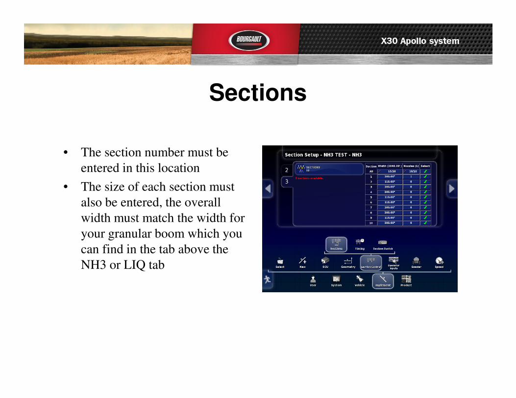
Sections
• The section number must be
entered in this location
• The size of each section must
also be entered, the overall
width must match the width for
your granular boom which you
can find in the tab above the
NH3 or LIQ tab
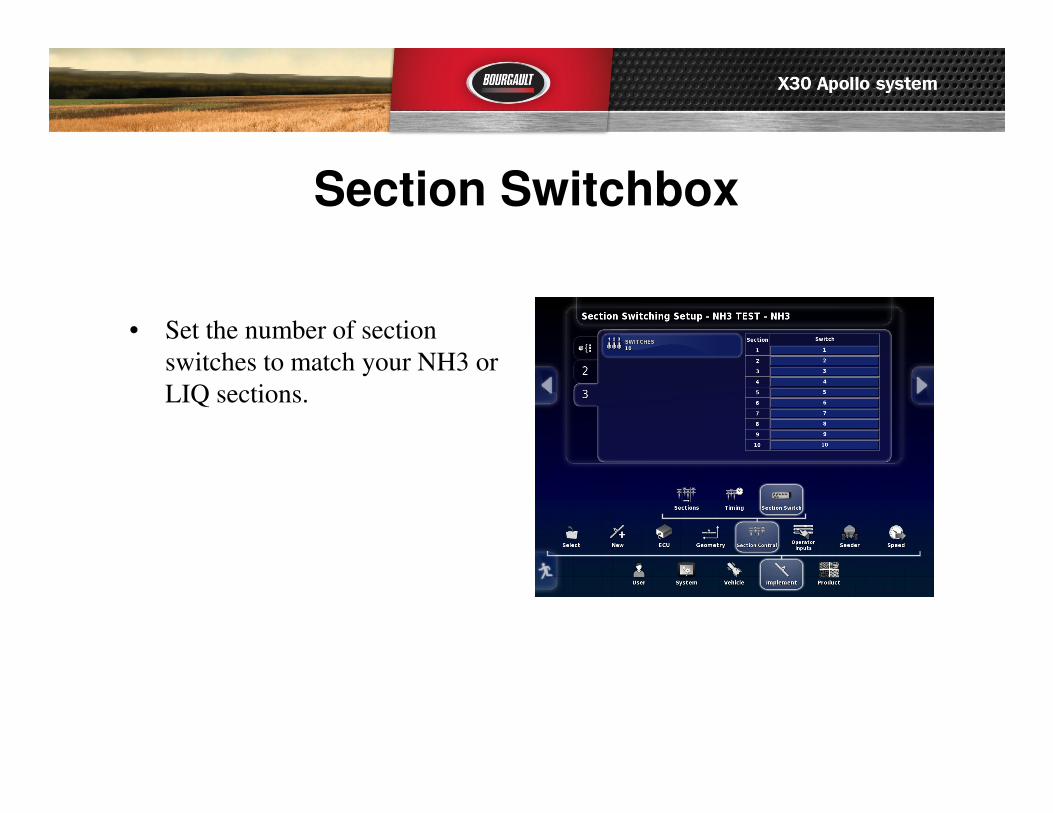
Section Switchbox
• Set the number of section
switches to match your NH3 or
LIQ sections.
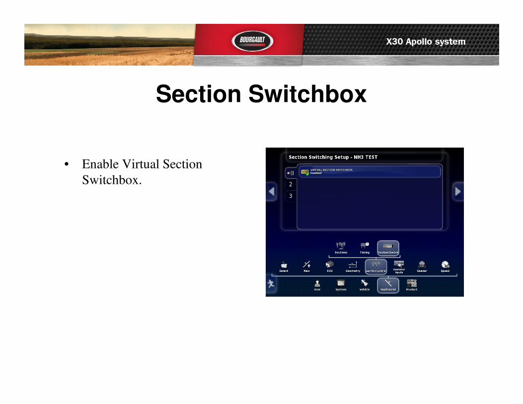
Section Switchbox
• Enable Virtual Section
Switchbox.

NH3 or LIQ Tank setup
• Go to the Tank setup tab to
enable and select section
control.
• You may also enter on off times
for reference while testing
system.
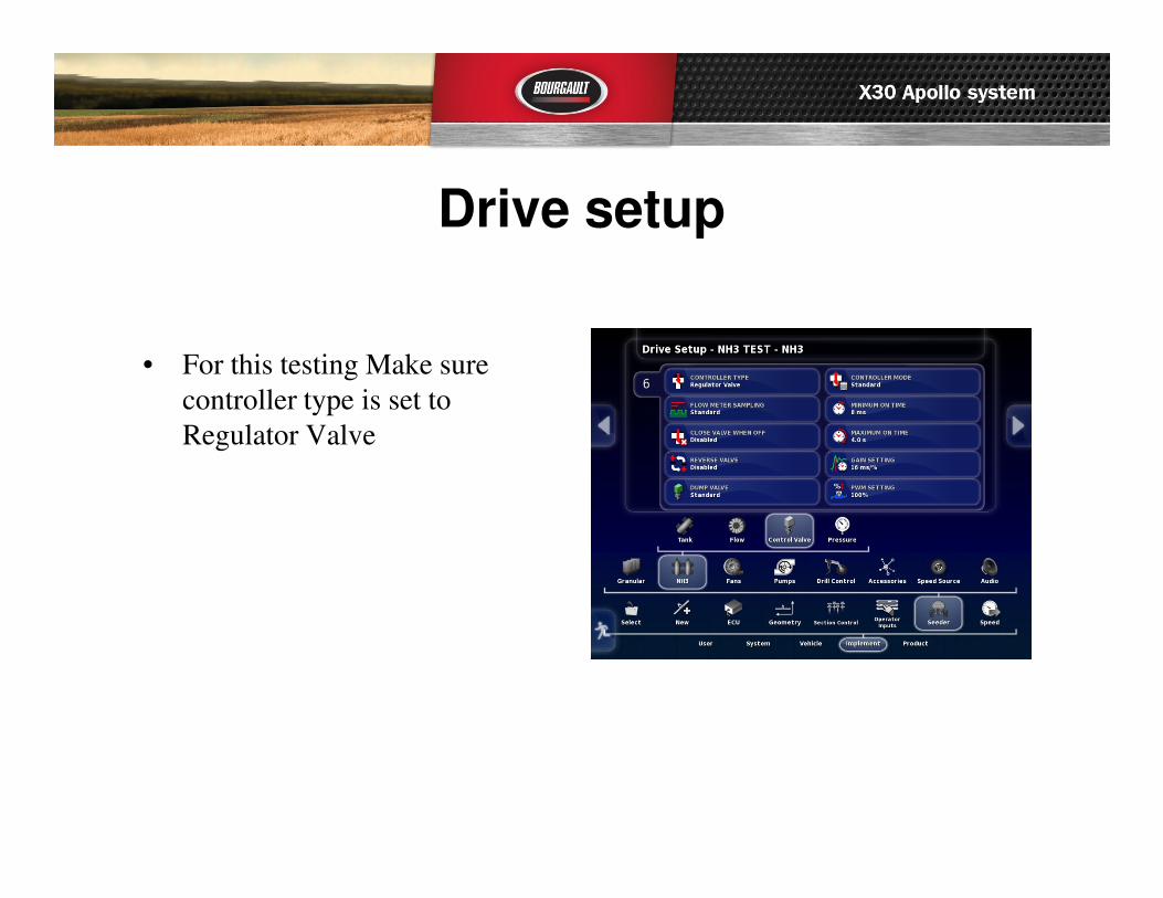
Drive setup
• For this testing Make sure
controller type is set to
Regulator Valve

Tank setup
• Make sure NH3 or LIQ tank is
enabled.
• For simplicity disable all
granular tanks.

Fans
• Disable all fans prior to testing.

SRC Setup
• Product must be selected NH3
or LIQ and fill tank.
• There must be a requested rate.
• Turn tank clutch on.

Configuration• Open Configuration tab and
enter Manual speed, select
Manual speed so tab is green.
• If uncalibrated touch Multi-tank
calibration tab, then Manual
Entry
• Enter calibration factor for NH3
or LIQ. This is generally a tag
on the flow meter or stamped
into the flow meter.
• For NH3 this must be in
Pulses/lb N
• For LIQUID it is Pulses/L

ASC and Switchbox mini views• Open the Auto section mini
view tab and turn ASC OFF
• Open the Switchbox mini view
tab and set to NH3 tab.
• At this point the X30 will be
ready to control NH3 or LIQ
• If Master switch is touched it
will cycle Green then back to
White back to Green etc.
• You are now ready to attach the
test harness to ensure the X30 is
working correctly.

Required test components• Test harness
• Part # 3151-47
• Bourgault dealer mandatory tool
• Can be used to test IB-1 or Apollo 1-6 section systems and Apollo 8-10 section systems.

Required test components• Topcon pulse generator
• Part # 3131-80
• Bourgault dealer mandatory
tool

3. Testing the X30 using test
harness 3132-47• Make sure loop cap “STD
valve” (3132-38-02) is installed
on harness 3132-38, as in top
picture to right for testing.
• Connect Pulse generator to test
harness at weather pack
connector, Bottom picture.
• Connect Test harness to Raven
adapter harness using
appropriate connector (6 or 10
section) 10 section connected in
picture to right.
• Do not connect any other
harness to the Test harness for
initial testing.

• You are now ready to begin testing
to confirm the X30 is properly
controlling the NH3/LIQ option.
• When testing 10-section 4 lights
should have power all the time,
when ECU’s are Synchronized,
SNSR PWR, BATT PWR 1,2 & 3.
• When testing 6-section 3 lights
should have power all the time,
when ECU’s are Synchronized,
SNSR PWR, BATT PWR 1 & 2.
• Turn all sections “ON” switchbox
• Testing 10-section “Master” should
cycle on/off when tank clutch or
Master clutch are turned on/off.
• On 6-section there is no “Master”,
when engaged the selected sections
should all be lit.

• REG 1A+ and 1B- will come on or
off as flow is changed using pulse
generator from above to below
desired rate and visa versa.
• REG 1A+ will be on or blinking
when X30 is trying to increase rate.
• REG 1B- will be on or blinking
when X30 is trying to decrease rate.
• Next you can check each of the
sections using the section switchbox
to confirm function of each section.
When section is on in monitor, light
on test harness should also be on for
that section.

Once testing with harness has confirmed that the X30 functions are working correctly. You will be able to test the Liquid or NH3 system.
1. Make sure you select the correct valve type – Regulator or Proportional
2. Make sure you have the correct cap on harness 3132-38 for your system.
3. If it still does not work correctly you can check voltages at the test lead or output connector. See pinout diagram, should have 12v on all pins corresponding to the lights if they are lit and set to Regulator valve.
4. If Voltages are correct and it still fails to work something is not working or pinned wrong on the Liquid or NH3 components. REMEMBER this is Pinned to match Raven harnessing if a different system is being used an adapter harness may be required.

Harness 3132-38

Harness 3132-38
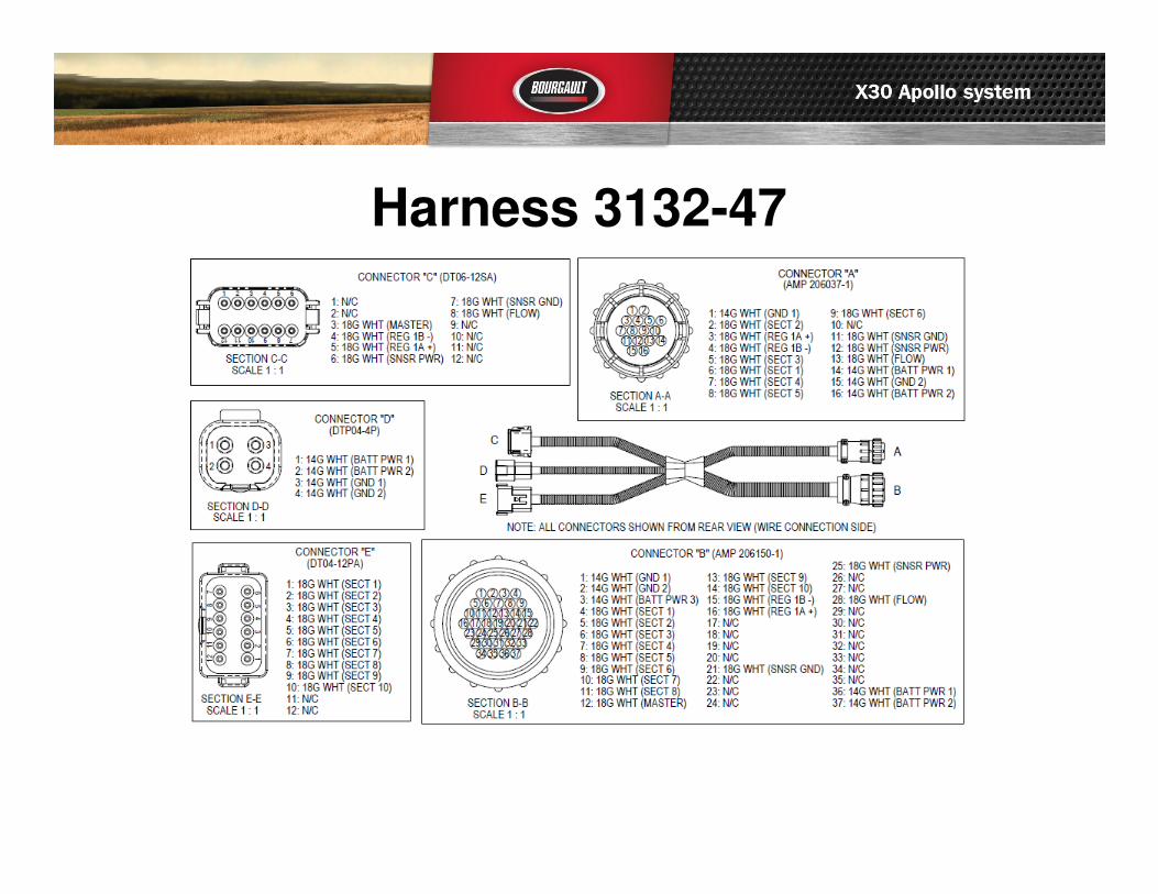
Harness 3132-47

Harness 3132-54

Harness 3132-66

Harness 3151-47

![[Co(NH3 6]Cl3](https://static.fdocuments.us/doc/165x107/62c22d2ed6734555b0515e2f/conh3-6cl3.jpg)


![23 - Berkeley City · Web view... (NH3)4Cl2]Cl ( [Co(NH3)4Cl2]+ + Cl-; (# of ions = 2) [Co(NH3)5Cl]Cl2 ... (III) chloride, [Co(NH3)5(NO2)]Cl2, and ... Copper Ceruloplasmin Hemoglobin](https://static.fdocuments.us/doc/165x107/5a9e9e6e7f8b9a0d158b9d45/doc23-berkeley-city-view-nh34cl2cl-conh34cl2-cl-of-ions.jpg)