Set5 Induction Motor Final
90
ELE 411: Induction Motors Instructor: Dr. Abbas A. Fardoun Department of Electrical Engineering United Arab Emirates University
-
Upload
electricstudent -
Category
Documents
-
view
221 -
download
0
Transcript of Set5 Induction Motor Final

8/6/2019 Set5 Induction Motor Final
http://slidepdf.com/reader/full/set5-induction-motor-final 1/90
ELE 411: Induction Motors
Instructor: Dr. Abbas A. Fardoun
Department of Electrical Engineering
United Arab Emirates University

8/6/2019 Set5 Induction Motor Final
http://slidepdf.com/reader/full/set5-induction-motor-final 2/90
2
Home Work
7.2, 7.3, 7.4, 7.5, 7.7, 7.8, 7.14, 7-16 & (7-19parts a,b & c)
8/6/2019 Set5 Induction Motor Final
http://slidepdf.com/reader/full/set5-induction-motor-final 3/90
3
Chapter # 7 Induction Motors
7.1- Induction Motors Construction
7.2- Basic Induction Motor Concept- Development of Induced Torque
- Concept of rotor sip
- Electrical frequency of rotor
7.3- Equivalent Circuit of Induction Motor
7.4- Power & Torque of Induction Motor- Losses & Power flow diagram
- Power & torque
- Separating rotor losses & power converted in IM
7.5- Induction Motor Torque Speed Characteristics- Derivation of Induced Torque Equation
- Comments on Torque-Speed Characteristics
- Maximum Torque in IM
7.6- Variation in IM Torque-Speed Characteristics
7.11- Determining Circuit Model parameters
8/6/2019 Set5 Induction Motor Final
http://slidepdf.com/reader/full/set5-induction-motor-final 4/90
Objectives
• The Objective of this lecture to discuss Induction Machine
construction. Reasons & applications for different type of rotor construction
• Basic operation theory of induction machine; definition of slipas related to machine rotor & rotational field speeds.
4

8/6/2019 Set5 Induction Motor Final
http://slidepdf.com/reader/full/set5-induction-motor-final 5/90
Outcomes
• Understand different types of rotors of IM.
• Understand theory of operation.
• Understand what “slip” means.
5
8/6/2019 Set5 Induction Motor Final
http://slidepdf.com/reader/full/set5-induction-motor-final 6/90
6
• Induction motor is the most rugged and the most widely used motor in
industry.
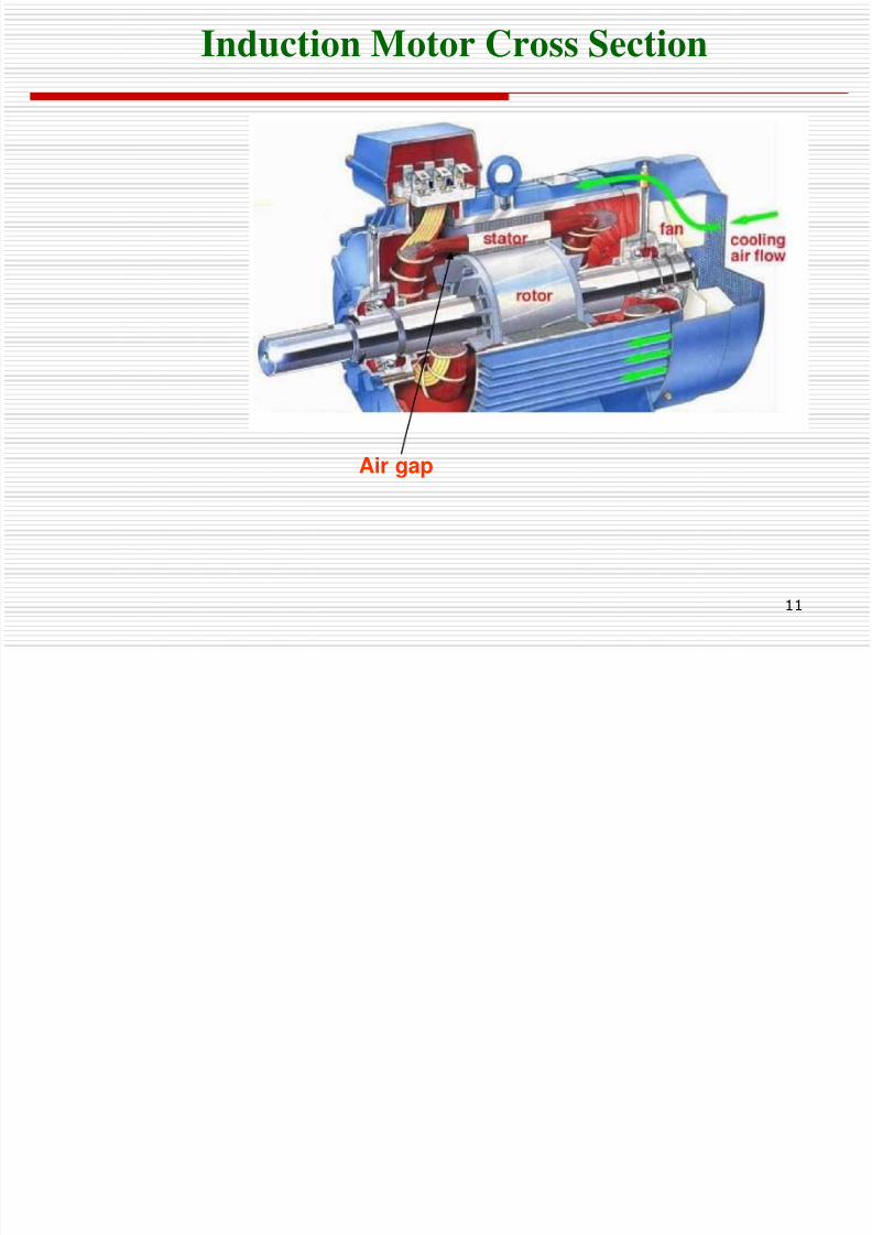
•Like any AC machine, the induction machine has a stator and a rotor mounted
on bearings and separated from stator by an air gap.
•
Both stator and rotor windings carry alternating currents. The alternatingcurrents (ac) are supplied directly to the stator winding and to the rotor winding
by induction.
• Reasons for the popularity of induction motors include:
- Simplicity- Reliability and low cost
- Minimal service requirement
- Good efficiency
Introduction
8/6/2019 Set5 Induction Motor Final
http://slidepdf.com/reader/full/set5-induction-motor-final 7/90
7
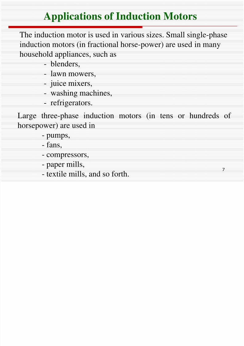
Large three-phase induction motors (in tens or hundreds of
horsepower) are used in- pumps,
- fans,
- compressors,
- paper mills,
- textile mills, and so forth.
The induction motor is used in various sizes. Small single-phase
induction motors (in fractional horse-power) are used in manyhousehold appliances, such as
- blenders,
- lawn mowers,
- juice mixers,- washing machines,
- refrigerators.
Applications of Induction Motors
8/6/2019 Set5 Induction Motor Final
http://slidepdf.com/reader/full/set5-induction-motor-final 8/90
8
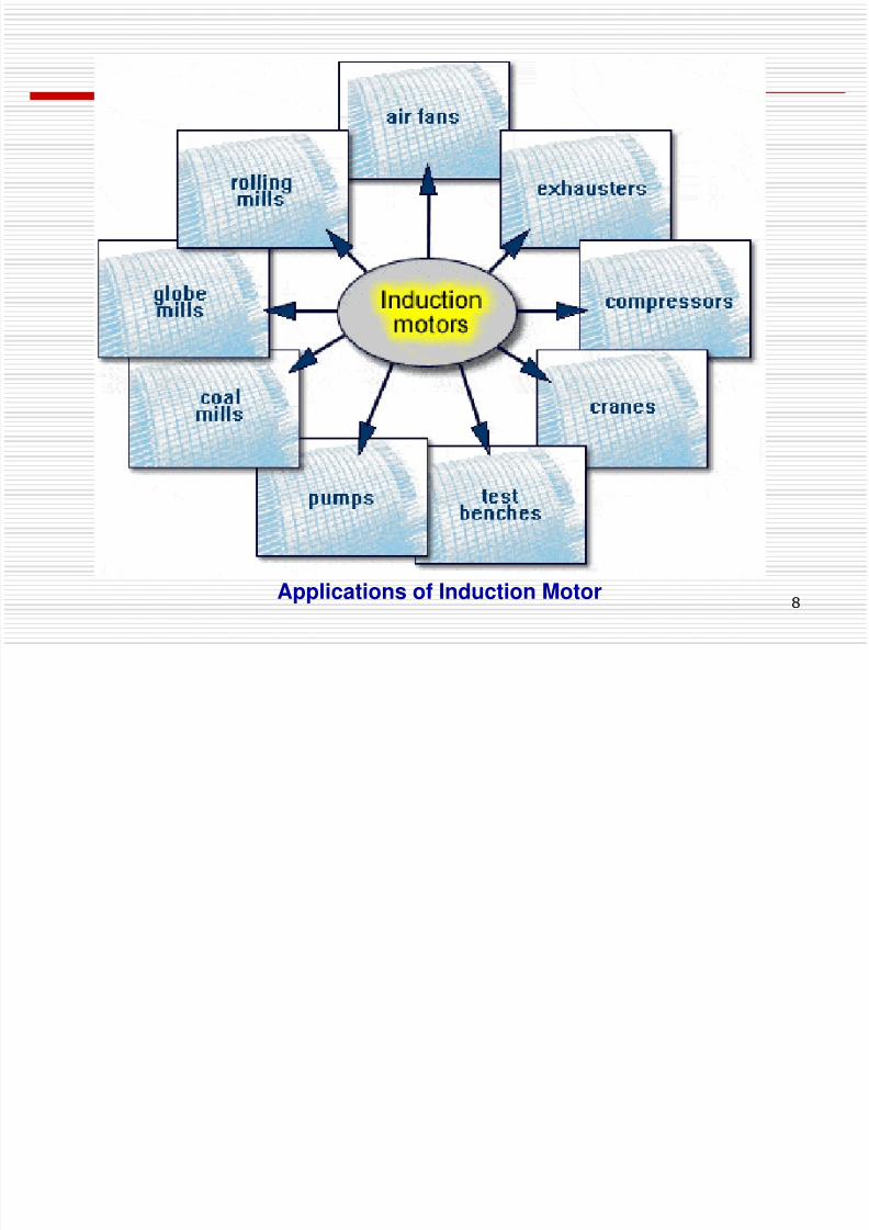
Applications of Induction Motor
8/6/2019 Set5 Induction Motor Final
http://slidepdf.com/reader/full/set5-induction-motor-final 9/90
9
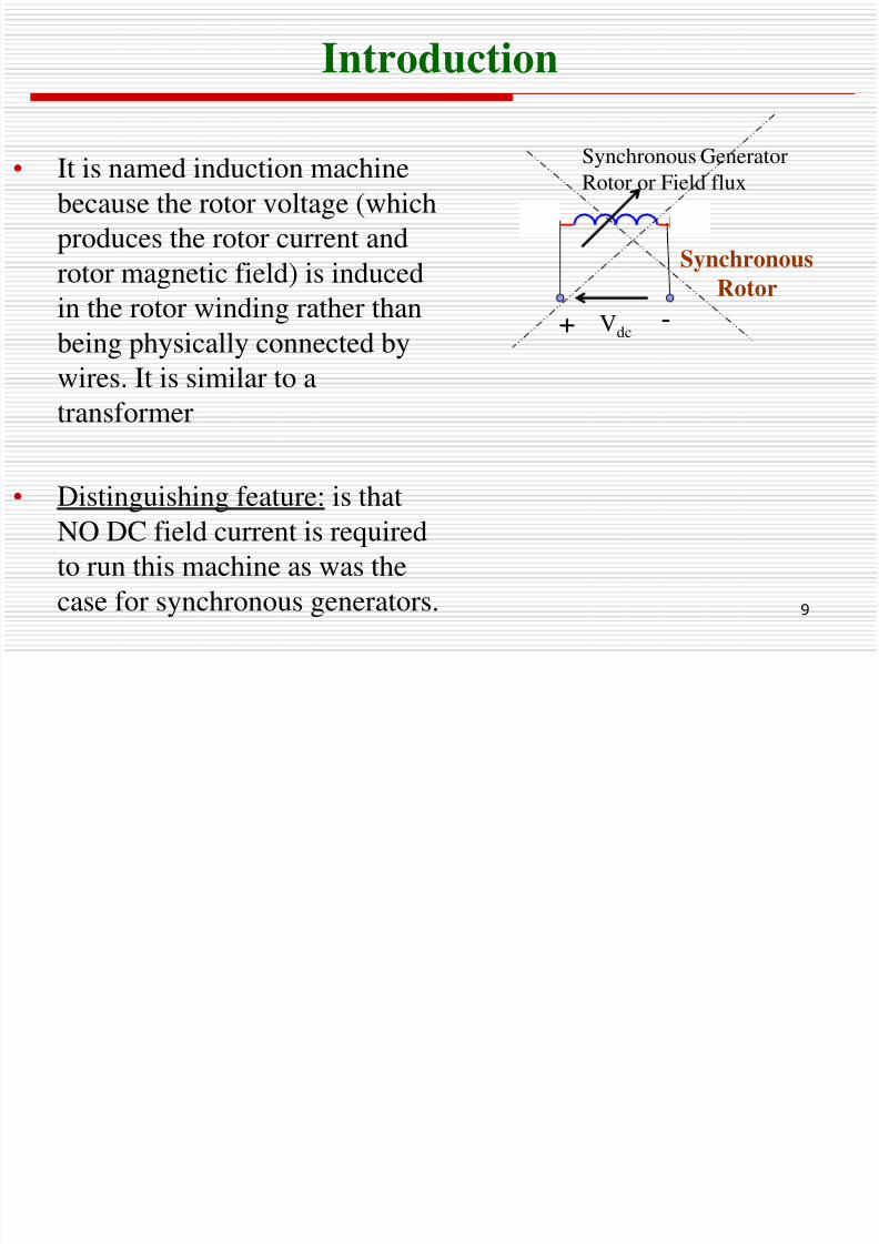
Introduction
• It is named induction machine
because the rotor voltage (which
produces the rotor current and
rotor magnetic field) is induced
in the rotor winding rather thanbeing physically connected by
wires. It is similar to a
transformer
• Distinguishing feature: is that
NO DC field current is required
to run this machine as was the
case for synchronous generators.
1 2
Vdc+ -
Synchronous
Rotor
Synchronous GeneratorRotor or Field flux
8/6/2019 Set5 Induction Motor Final
http://slidepdf.com/reader/full/set5-induction-motor-final 10/90
10
• Two Types of Induction machines known as Wound rotor & Squirrel-cage machines
•Both Machines has a stator similar to that of Synchronous Generator.
•They differ in rotor construction (same stator):
- Wound-rotor
- Squirrel-cage rotor
7.1- Construction Of Induction Motors/Rotor
8/6/2019 Set5 Induction Motor Final
http://slidepdf.com/reader/full/set5-induction-motor-final 11/90
11
Induction Motor Cross Section
Air gap
8/6/2019 Set5 Induction Motor Final
http://slidepdf.com/reader/full/set5-induction-motor-final 12/90
12
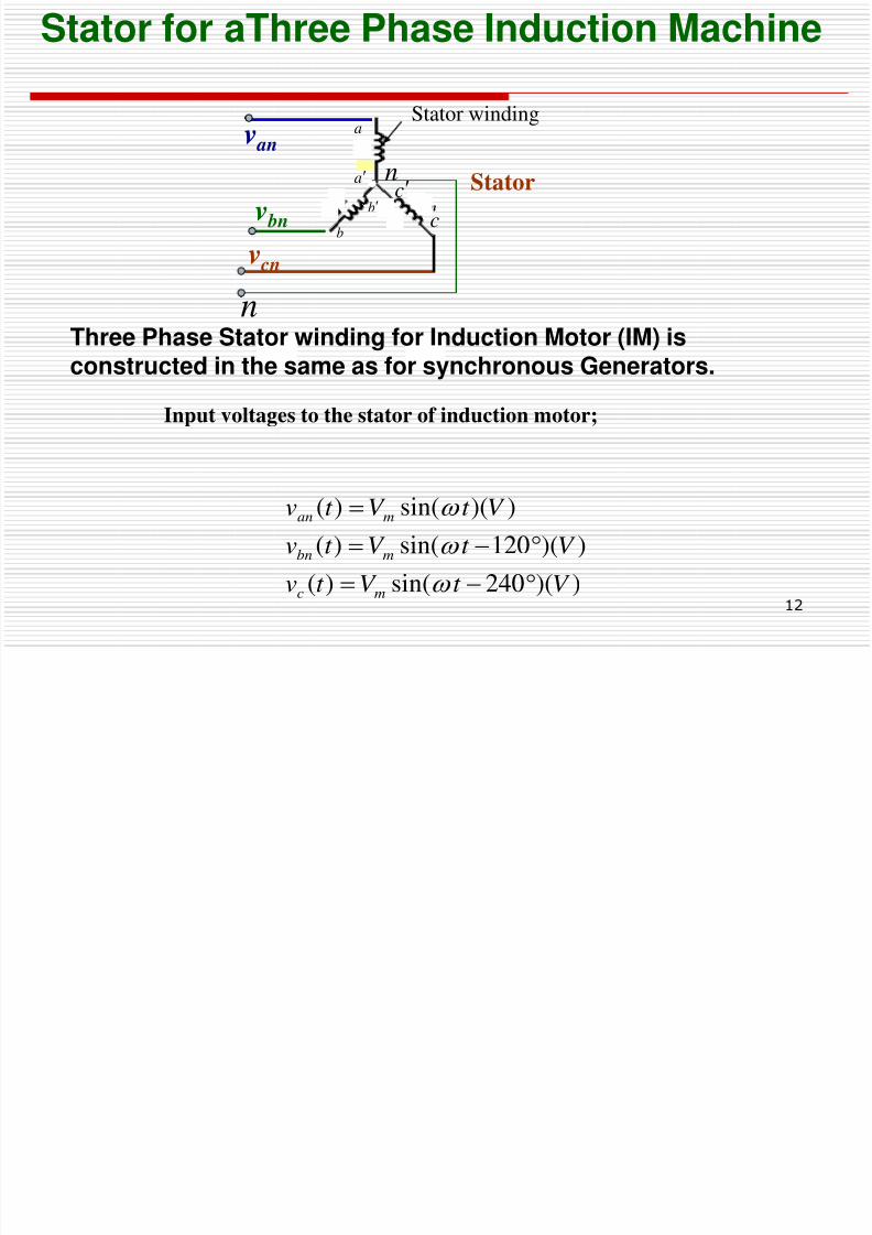
Input voltages to the stator of induction motor;
Stator for aThree Phase Induction Machine
))(240sin()(
))(120sin()(
))(sin()(
V t V t v
V t V t v
V t V t v
mc
mbn
man
1 : n
Stator
v an
v bn
v cn
Stator winding
na
a
n
b
b
c
c
Three Phase Stator winding for Induction Motor (IM) isconstructed in the same as for synchronous Generators.
8/6/2019 Set5 Induction Motor Final
http://slidepdf.com/reader/full/set5-induction-motor-final 13/90
13
• Wound-rotor motor: Rotor has distributed windings are similar tostator windings.
•Rotor terminals are made accessible to external loads through
brushes bearing on slip rings.
•
Connected to external circuit such as to a resistance is very handyfor the purpose of speed control of the induction motor.
•Squirrel-cage motor: windings are made of conducting bars embedded
in the rotor and short-circuited at each end by conducting end rings.
•The rotor terminals are thus inaccessible in a squirrel-cage
construction.
•Squirrel cage induction machine is simpler, more reliable,
efficient, economical and more rugged than the wound-rotor
induction machine because there are no brushes, no slip rings.
7.1- Construction Of Induction Motors/Rotor
8/6/2019 Set5 Induction Motor Final
http://slidepdf.com/reader/full/set5-induction-motor-final 14/90
14
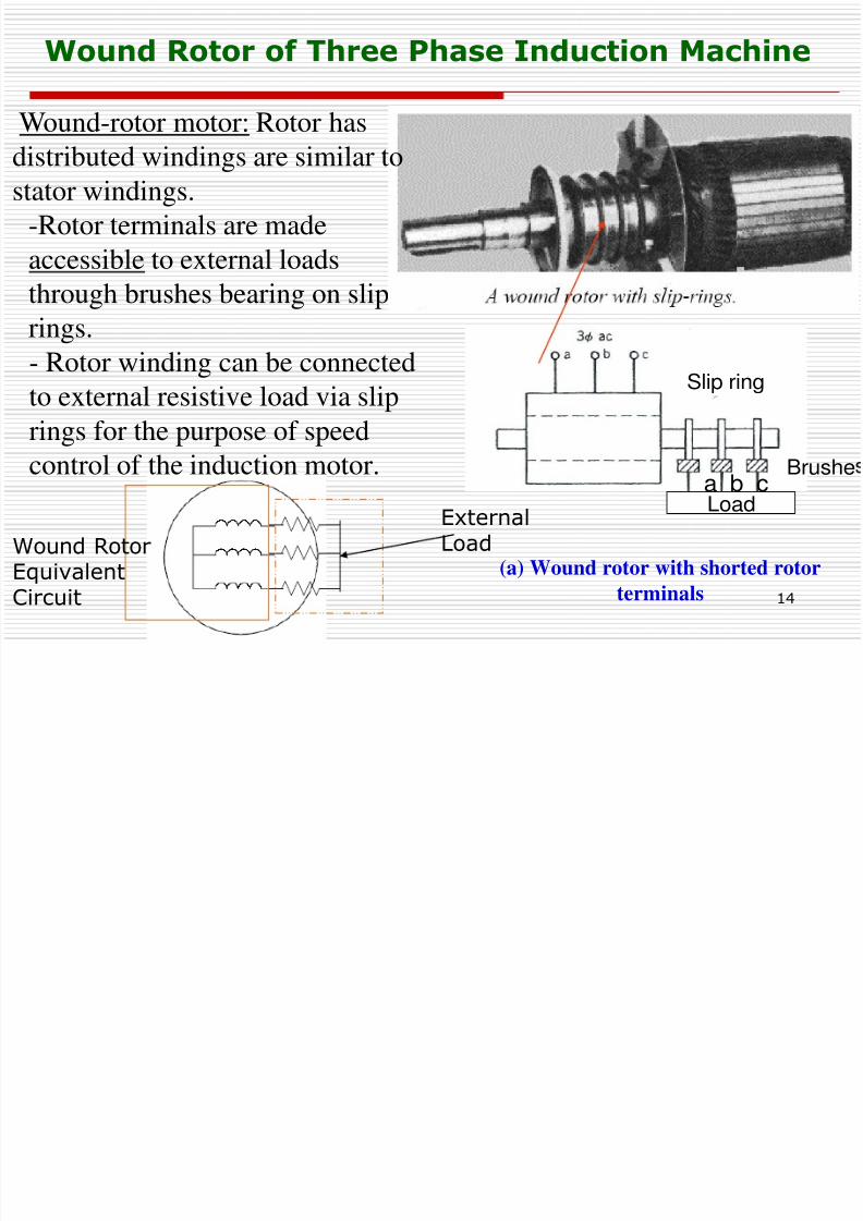
Wound Rotor of Three Phase Induction Machine
Slip ring
Brushea b cLoad
(a) Wound rotor with shorted rotor
terminals
Wound-rotor motor: Rotor has
distributed windings are similar tostator windings.
-Rotor terminals are made
accessible to external loads
through brushes bearing on sliprings.
- Rotor winding can be connected
to external resistive load via slip
rings for the purpose of speed
control of the induction motor.
ExternalLoadWound Rotor
Equivalent
Circuit
8/6/2019 Set5 Induction Motor Final
http://slidepdf.com/reader/full/set5-induction-motor-final 15/90
15
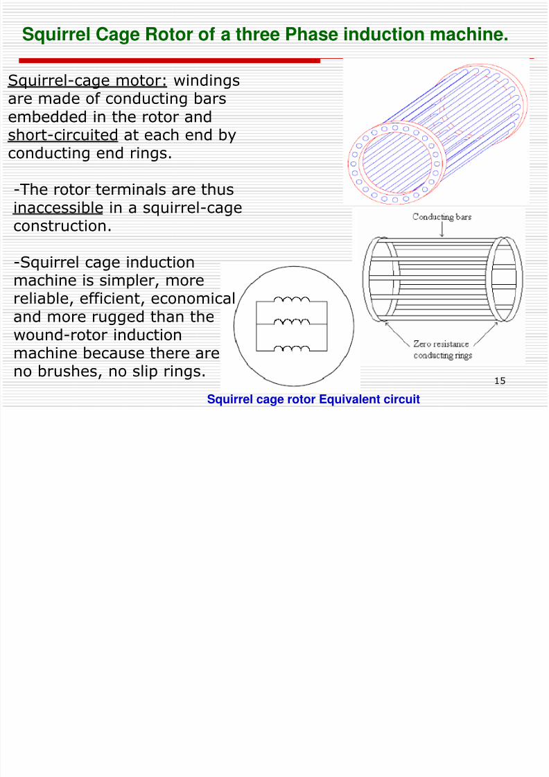
Squirrel Cage Rotor of a three Phase induction machine.
Squirrel cage rotor Equivalent circuit
Squirrel-cage motor: windings
are made of conducting barsembedded in the rotor andshort-circuited at each end byconducting end rings.
-The rotor terminals are thusinaccessible in a squirrel-cageconstruction.
-Squirrel cage induction
machine is simpler, morereliable, efficient, economicaland more rugged than thewound-rotor inductionmachine because there areno brushes, no slip rings.
8/6/2019 Set5 Induction Motor Final
http://slidepdf.com/reader/full/set5-induction-motor-final 16/90
16
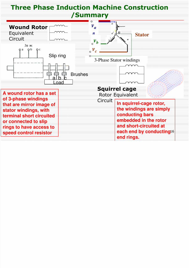
Three Phase Induction Machine Construction/Summary
1 : n
Stator
v a
n
v b
nv c
n3-Phase Stator windings
na
a
Slip ring
Brushesa b cLoad
A wound rotor has a set
of 3-phase windingsthat are mirror image ofstator windings, withterminal short circuitedor connected to sliprings to have access to
speed control resistor
In squirrel-cage rotor,the windings are simplyconducting barsembedded in the rotorand short-circuited at
each end by conductingend rings.
Wound Rotor
EquivalentCircuit
Squirrel cageRotor Equivalent
Circuit
8/6/2019 Set5 Induction Motor Final
http://slidepdf.com/reader/full/set5-induction-motor-final 17/90
17
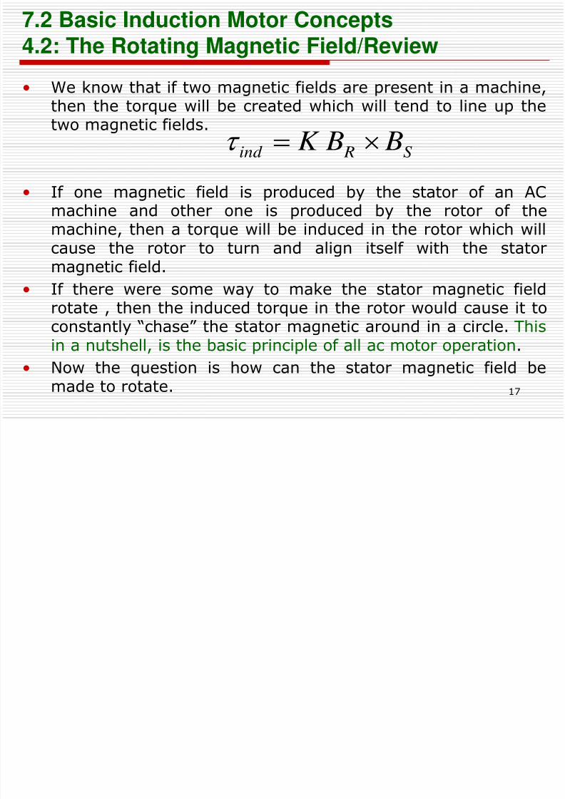
• We know that if two magnetic fields are present in a machine,
then the torque will be created which will tend to line up thetwo magnetic fields.
• If one magnetic field is produced by the stator of an ACmachine and other one is produced by the rotor of themachine, then a torque will be induced in the rotor which willcause the rotor to turn and align itself with the statormagnetic field.
• If there were some way to make the stator magnetic fieldrotate , then the induced torque in the rotor would cause it toconstantly “chase” the stator magnetic around in a circle. Thisin a nutshell, is the basic principle of all ac motor operation.
• Now the question is how can the stator magnetic field bemade to rotate.
7.2 Basic Induction Motor Concepts4.2: The Rotating Magnetic Field/Review
S Rind B BK
8/6/2019 Set5 Induction Motor Final
http://slidepdf.com/reader/full/set5-induction-motor-final 18/90
18
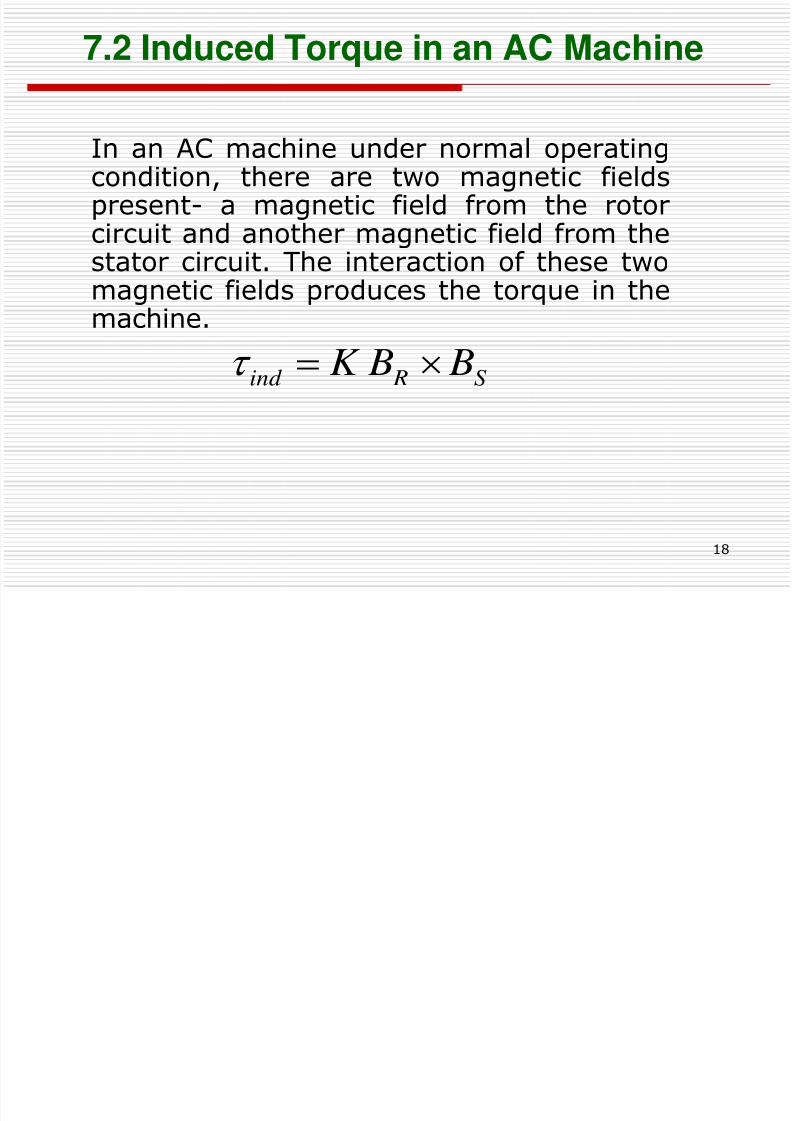
7.2 Induced Torque in an AC Machine
In an AC machine under normal operatingcondition, there are two magnetic fieldspresent- a magnetic field from the rotorcircuit and another magnetic field from thestator circuit. The interaction of these twomagnetic fields produces the torque in themachine.
S Rind B BK
8/6/2019 Set5 Induction Motor Final
http://slidepdf.com/reader/full/set5-induction-motor-final 19/90
19
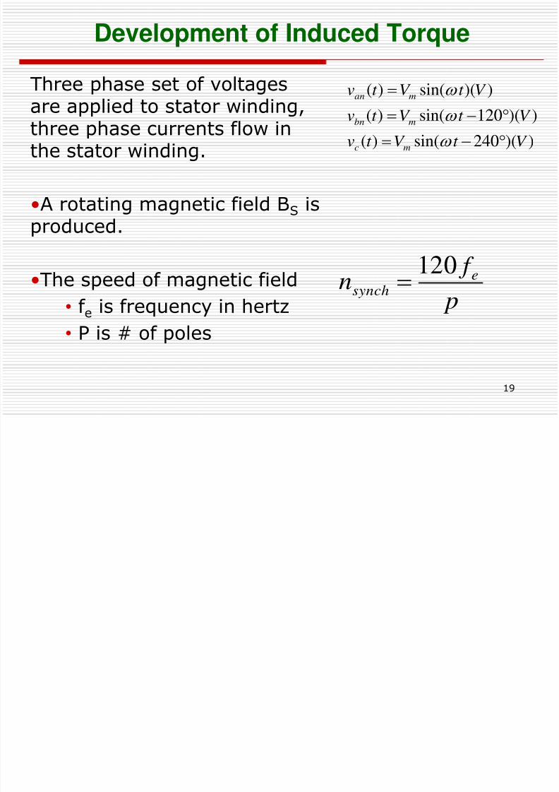
Development of Induced Torque
Three phase set of voltages
are applied to stator winding,three phase currents flow inthe stator winding.
•A rotating magnetic field BS isproduced.
•The speed of magnetic field
• f e is frequency in hertz
• P is # of poles
p
f n e
synch
120
))(240sin()(
))(120sin()(
))(sin()(
V t V t v
V t V t v
V t V t v
mc
mbn
man
8/6/2019 Set5 Induction Motor Final
http://slidepdf.com/reader/full/set5-induction-motor-final 20/90
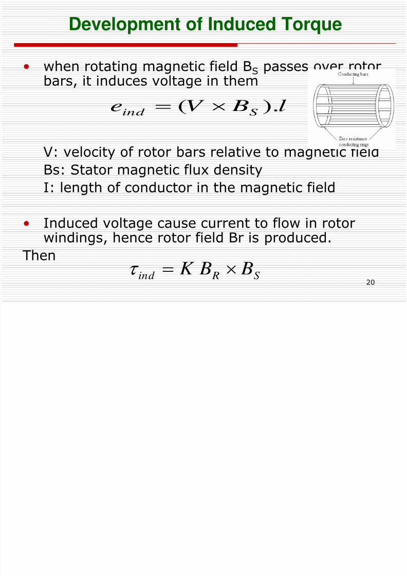
20
• when rotating magnetic field BS passes over rotorbars, it induces voltage in them
V: velocity of rotor bars relative to magnetic field
Bs: Stator magnetic flux density
I: length of conductor in the magnetic field
• Induced voltage cause current to flow in rotorwindings, hence rotor field Br is produced.
Then
l BV e Sind ).(
S Rind B BK
Development of Induced Torque
8/6/2019 Set5 Induction Motor Final
http://slidepdf.com/reader/full/set5-induction-motor-final 21/90
21
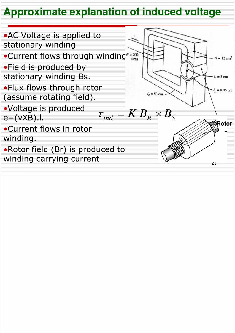
Approximate explanation of induced voltage
•AC Voltage is applied to
stationary winding
•Current flows through winding
•Field is produced bystationary winding Bs.
•Flux flows through rotor(assume rotating field).
•Voltage is producede=(vXB).l.
•Current flows in rotorwinding.
•Rotor field (Br) is produced towinding carrying current
Rotor
S Rind B BK
8/6/2019 Set5 Induction Motor Final
http://slidepdf.com/reader/full/set5-induction-motor-final 22/90
22
Induction Motors/review
Operation Principle
• The three-phase stator is supplied by balancedthree-phase voltage that drives an ac magnetizingcurrent through each phase winding
• The magnetizing current in each phase generates
a pulsating ac flux.• The total flux in the machine is the sum of the
three fluxes
• The summation of the three ac fluxes results in arotating flux, which turns with constant speed and
has constant amplitude
8/6/2019 Set5 Induction Motor Final
http://slidepdf.com/reader/full/set5-induction-motor-final 23/90
23
Induction Motors/review
Operation Principle• The rotating flux induces avoltage in the short-circuitedbars of the rotor. This voltagedrives current through the bars.
• The induced voltage isproportional with the differenceof motor and synchronousspeed. Consequently the motorspeed is less than the
synchronous speed• The interaction of the rotating
flux and the rotor currentgenerates a force that drivesthe motor.
S Rind B BK
l BV e Sind ).(
8/6/2019 Set5 Induction Motor Final
http://slidepdf.com/reader/full/set5-induction-motor-final 24/90
24
• The motor will start rotating, there is a limit to the
speed of rotor.
• If rotor speed becomes equal to synchronous speedthen rotor bars will be stationary relative to themagnetic field, and there would be no induced
voltage.• If then current in rotor bars is zero
No rotor current
No torque
• How about when the rotor is not rotating (0 speed)?
Voltage is induced at the same frequency as thatof the stator.
What is output power in this case?
0ind e
Concept of Rotor Slip
8/6/2019 Set5 Induction Motor Final
http://slidepdf.com/reader/full/set5-induction-motor-final 25/90
25
Concept of Rotor Slip
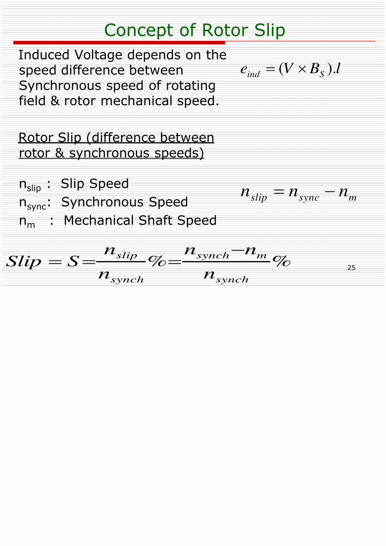
Induced Voltage depends on the
speed difference betweenSynchronous speed of rotatingfield & rotor mechanical speed.
Rotor Slip (difference betweenrotor & synchronous speeds)
nslip : Slip Speed
nsync: Synchronous Speednm : Mechanical Shaft Speed
%%
synch
msynch
synch
slip
n
nn
n
nSSlip
msyncslip nnn
l BV e Sind ).(
8/6/2019 Set5 Induction Motor Final
http://slidepdf.com/reader/full/set5-induction-motor-final 26/90
26
Concept of Rotor Slip
Rotating Transformer
- Induction motor works by induced voltage and current in rotor,therefore some times called as rotating transformer.
- Primary (Stator) induces voltage in Secondary (Rotor)
- Secondary frequency:
If rotor is locked (S=1), then secondary frequency is sameas primary. However output power is zero because
P= torque X speed = If rotor turns at synchronous speed the Rotor frequency
will be zero since no voltage is induced.
8/6/2019 Set5 Induction Motor Final
http://slidepdf.com/reader/full/set5-induction-motor-final 27/90
27
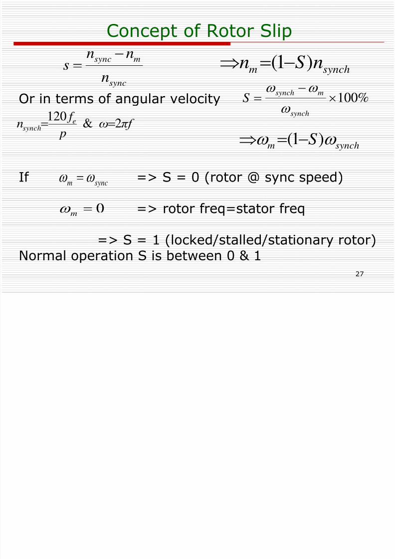
Concept of Rotor Slip
Or in terms of angular velocity
If => S = 0 (rotor @ sync speed)
=> rotor freq=stator freq
=> S = 1 (locked/stalled/stationary rotor)Normal operation S is between 0 & 1
synchm nSn )1(
syncm
0m
%100
synch
msynchS
sync
msync
n
nn
s
synchm S )1(
πf ω p
f n esynch 2 &
120
8/6/2019 Set5 Induction Motor Final
http://slidepdf.com/reader/full/set5-induction-motor-final 28/90
28
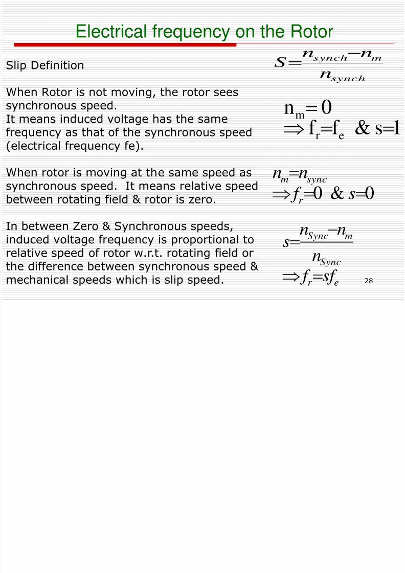
Electrical frequency on the Rotor
0& 0
s f
nn
r
syncm
synch
msynch
n
nnS
1s& f f 0n
er
m
Slip Definition
When Rotor is not moving, the rotor seessynchronous speed.It means induced voltage has the samefrequency as that of the synchronous speed
(electrical frequency fe).
When rotor is moving at the same speed assynchronous speed. It means relative speedbetween rotating field & rotor is zero.
In between Zero & Synchronous speeds,induced voltage frequency is proportional torelative speed of rotor w.r.t. rotating field orthe difference between synchronous speed &
mechanical speeds which is slip speed. er
Sync
mSync
sf f
n
nns
8/6/2019 Set5 Induction Motor Final
http://slidepdf.com/reader/full/set5-induction-motor-final 29/90
29
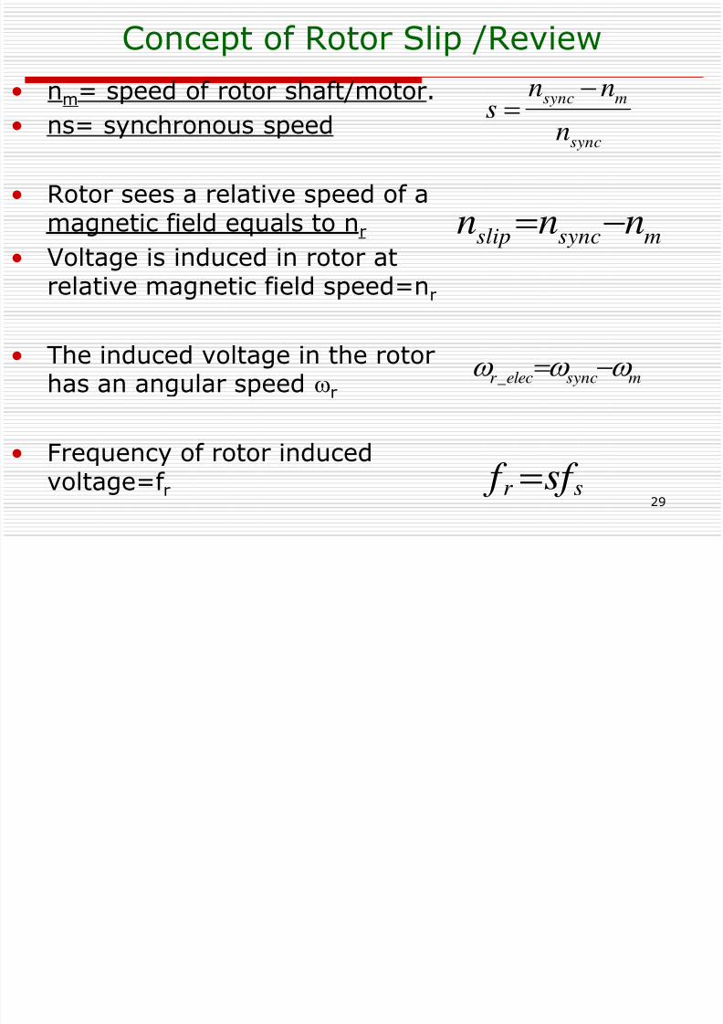
Concept of Rotor Slip /Review
• nm= speed of rotor shaft/motor.
• ns= synchronous speed
• Rotor sees a relative speed of amagnetic field equals to nr
• Voltage is induced in rotor atrelative magnetic field speed=nr
• The induced voltage in the rotor
has an angular speed r
• Frequency of rotor inducedvoltage=f r sr sf f
msyncslip nnn
msyncelecr
_
sync
msync
n
nns
Rotor induced voltage & rotor electrical

8/6/2019 Set5 Induction Motor Final
http://slidepdf.com/reader/full/set5-induction-motor-final 30/90
30
Rotor voltage frequency, fR
Rotor speed (rpm)Slip
ERof stator
Rotor speed (rpm)Slip
0 no load 1 0
0 no load1 0
Rotor voltage, ER
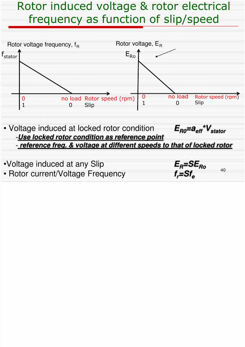
Rotor induced voltage & rotor electricalfrequency as function of slip/speed
•Voltage induced at locked rotor condition E R0 =a eff *V stator
-Use locked rotor condition as reference point - reference freq. & voltage at different speeds to that of locked rotor
•Voltage induced at any Slip E R =SE Ro
• Rotor current/Voltage Frequency f r =Sf e
8/6/2019 Set5 Induction Motor Final
http://slidepdf.com/reader/full/set5-induction-motor-final 31/90
31
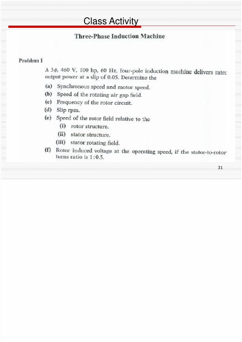
Class Activity
8/6/2019 Set5 Induction Motor Final
http://slidepdf.com/reader/full/set5-induction-motor-final 32/90
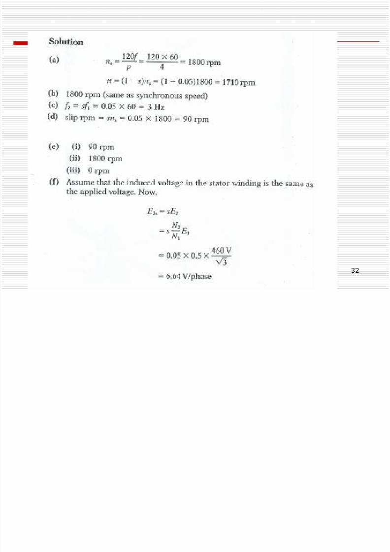
32
Agenda
8/6/2019 Set5 Induction Motor Final
http://slidepdf.com/reader/full/set5-induction-motor-final 33/90
33
Agenda
• Review of Slip concept• Derivation of IM Equivalent Circuit Parameters
measurement• Example problem• Power & Torque of Induction Motor
- Losses & Power flow diagram- Power & torque- Separating rotor losses & power converted in IM
8/6/2019 Set5 Induction Motor Final
http://slidepdf.com/reader/full/set5-induction-motor-final 34/90
34
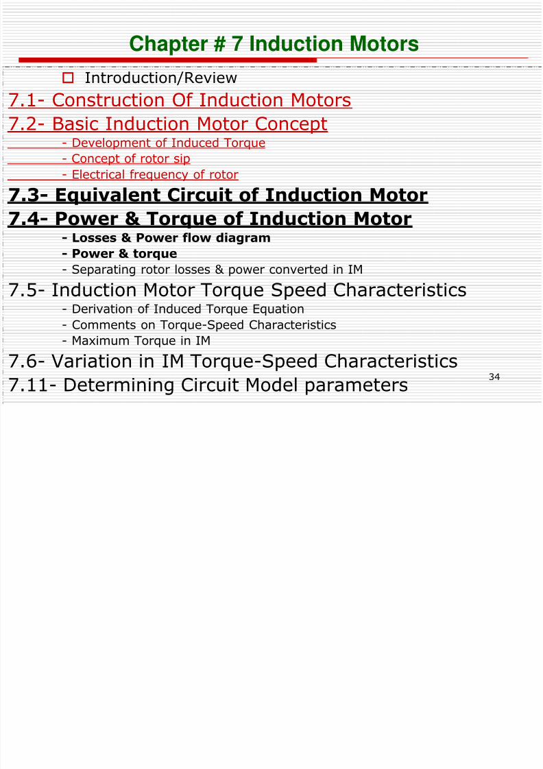
Chapter # 7 Induction Motors
Introduction/Review
7.1- Construction Of Induction Motors7.2- Basic Induction Motor Concept
- Development of Induced Torque
- Concept of rotor sip
- Electrical frequency of rotor
7.3- Equivalent Circuit of Induction Motor7.4- Power & Torque of Induction Motor
- Losses & Power flow diagram
- Power & torque
- Separating rotor losses & power converted in IM
7.5- Induction Motor Torque Speed Characteristics- Derivation of Induced Torque Equation
- Comments on Torque-Speed Characteristics
- Maximum Torque in IM
7.6- Variation in IM Torque-Speed Characteristics
7.11- Determining Circuit Model parameters
C t f R t Sli /R i
8/6/2019 Set5 Induction Motor Final
http://slidepdf.com/reader/full/set5-induction-motor-final 35/90
35
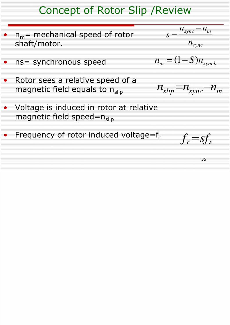
Concept of Rotor Slip /Review
• nm= mechanical speed of rotor
shaft/motor.
• ns= synchronous speed
• Rotor sees a relative speed of amagnetic field equals to nslip
• Voltage is induced in rotor at relativemagnetic field speed=n
slip
• Frequency of rotor induced voltage=f rsr sf f
msyncslip nnn
sync
msync
n
nns
synchm nSn )1(
8/6/2019 Set5 Induction Motor Final
http://slidepdf.com/reader/full/set5-induction-motor-final 36/90
36
7.3 Equivalent Circuit of an Induction Machine
• An induction motor is called a singly excitedmachine (as opposed to a doubly excitedsynchronous machine), since power is suppliedonly to the stator circuit. Because induction
motor does not have an independent field circuitits model will not contain an internal voltagesource such as internal generated voltage EA in asynchronous machine.
• We will begin with the transformer model.
8/6/2019 Set5 Induction Motor Final
http://slidepdf.com/reader/full/set5-induction-motor-final 37/90
37
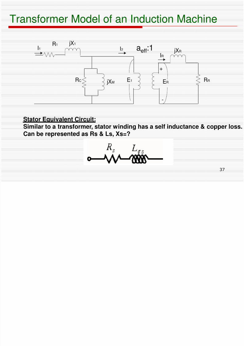
Transformer Model of an Induction Machine
jXR
RR
IR
ERE1 jXM
I2 jX1R1I1
RC
+
-
Stator Equivalent Circuit:
Similar to a transformer, stator winding has a self inductance & copper loss.Can be represented as Rs & Ls, Xs=?
aeff:1
8/6/2019 Set5 Induction Motor Final
http://slidepdf.com/reader/full/set5-induction-motor-final 38/90
38
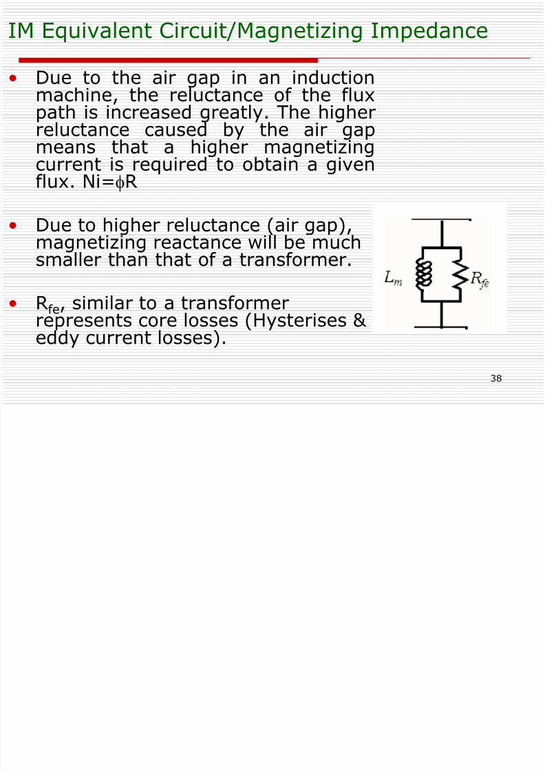
IM Equivalent Circuit/Magnetizing Impedance
• Due to the air gap in an induction
machine, the reluctance of the fluxpath is increased greatly. The higherreluctance caused by the air gapmeans that a higher magnetizingcurrent is required to obtain a givenflux. Ni=fR
• Due to higher reluctance (air gap),magnetizing reactance will be muchsmaller than that of a transformer.
• Rfe, similar to a transformerrepresents core losses (Hysterises & eddy current losses).
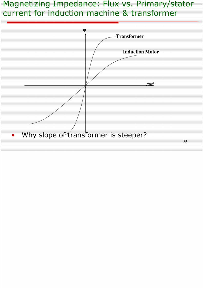
Magnetizing Impedance: Flux vs. Primary/stator
8/6/2019 Set5 Induction Motor Final
http://slidepdf.com/reader/full/set5-induction-motor-final 39/90
39
• Why slope of transformer is steeper?
Transformer
Induction Motor
φ
mmf
Magnetizing Impedance: Flux vs. Primary/statorcurrent for induction machine & transformer
Rotor induced voltage & rotor electrical
8/6/2019 Set5 Induction Motor Final
http://slidepdf.com/reader/full/set5-induction-motor-final 40/90
40
Rotor voltage frequency, fR
Rotor speed (rpm)Slip
ERof stator
Rotor speed (rpm)Slip
0 no load 1 0
0 no load1 0
Rotor voltage, ER
Rotor induced voltage & rotor electricalfrequency as function of slip/speed
•
Voltage induced at locked rotor condition E R0 =a eff *V stator -Use locked rotor condition as reference point - reference freq. & voltage at different speeds to that of locked rotor
•Voltage induced at any Slip E R =SE Ro
• Rotor current/Voltage Frequency f r =Sf e
8/6/2019 Set5 Induction Motor Final
http://slidepdf.com/reader/full/set5-induction-motor-final 41/90
41
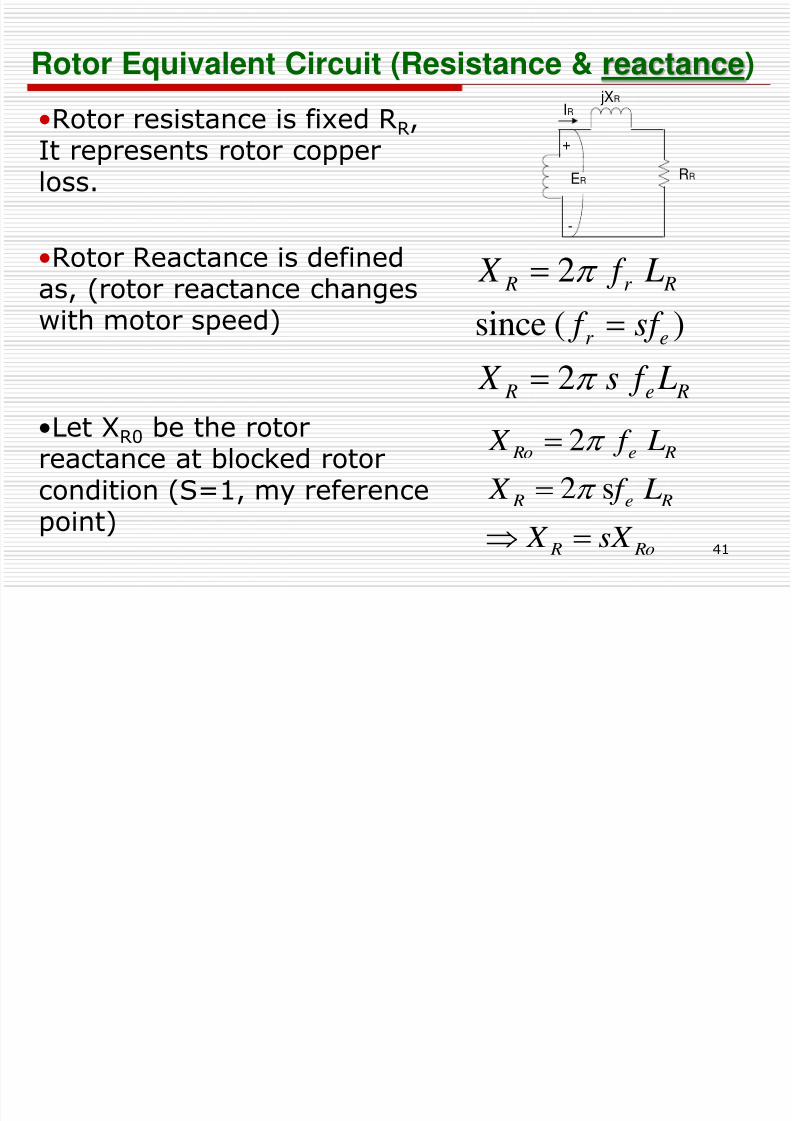
Rotor Equivalent Circuit (Resistance & reactance)
•Rotor resistance is fixed RR,
It represents rotor copperloss.
•Rotor Reactance is defined
as, (rotor reactance changeswith motor speed)
•Let XR0 be the rotorreactance at blocked rotorcondition (S=1, my referencepoint)
2
)(since 2
Re R
er
Rr R
L f s X
sf f L f X
Ro R
Re R
Re Ro
sX X
L f X
L f X
s2
2
jXR
RR
IR
ER
+
-
8/6/2019 Set5 Induction Motor Final
http://slidepdf.com/reader/full/set5-induction-motor-final 42/90
42
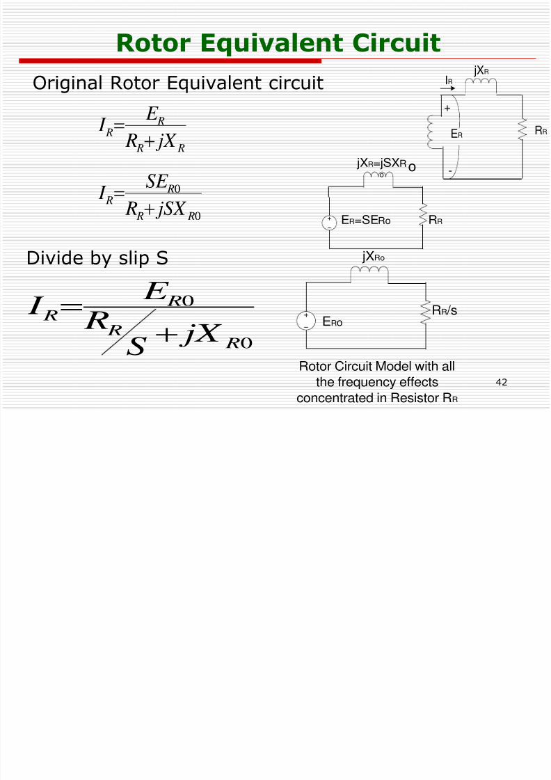
0
0
R R
R R
jX S
R E I
Rotor Equivalent Circuit
Original Rotor Equivalent circuit
Divide by slip S
0
0
R R
R R
R R
R R
jSX R
SE
I
jX R
E I
RR
jXR=jSXRo
ER=SERo
RR /s
jXRo
ERo
Rotor Circuit Model with all
the frequency effectsconcentrated in Resistor RR
o
jXR
RR
IR
ER
+
-
8/6/2019 Set5 Induction Motor Final
http://slidepdf.com/reader/full/set5-induction-motor-final 43/90
43
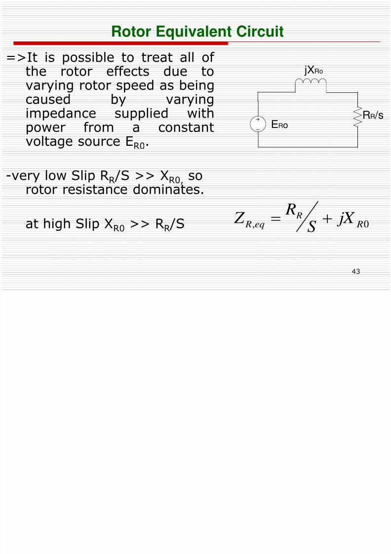
Rotor Equivalent Circuit
=>It is possible to treat all of
the rotor effects due tovarying rotor speed as beingcaused by varyingimpedance supplied withpower from a constant
voltage source ER0.
-very low Slip RR /S >> XR0, sorotor resistance dominates.
at high Slip XR0 >> RR /S
RR /s
jXRo
ERo
0, R R
eq R jX S
R Z
8/6/2019 Set5 Induction Motor Final
http://slidepdf.com/reader/full/set5-induction-motor-final 44/90
44
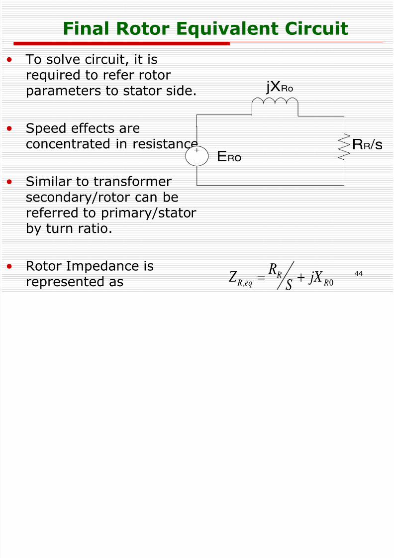
Final Rotor Equivalent Circuit
• To solve circuit, it is
required to refer rotorparameters to stator side.
• Speed effects are
concentrated in resistance.
• Similar to transformersecondary/rotor can be
referred to primary/statorby turn ratio.
• Rotor Impedance is
represented as 0, R Req R jX S R
Z
RR /s
jXRo
ERo
8/6/2019 Set5 Induction Motor Final
http://slidepdf.com/reader/full/set5-induction-motor-final 45/90
45
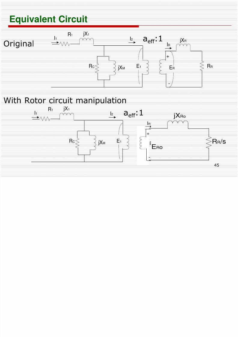
Equivalent Circuit
jXR
RR
IR
ERE1 jXM
I2 jX1R1
I1
RC
+
-
E1 jXM
I2 jX1R1
I1
RC RR /s
jXRo
ERo
IR
+
-
Original
With Rotor circuit manipulation
aeff
:1
aeff :1
8/6/2019 Set5 Induction Motor Final
http://slidepdf.com/reader/full/set5-induction-motor-final 46/90
46
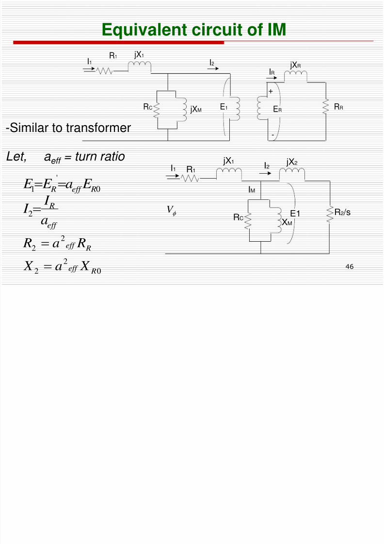
Let, a eff = turn ratio
-Similar to transformer
Equivalent circuit of IM
eff
R
Reff R
a I I
E a E E
2
0
'
1
0
2
2
2
2
Reff
Reff
X a X
Ra R
I2
XM
IM
jX1
R1I1
RCR2 /s
jX2
f V E1
jXR
RR
IR
ERE1 jXM
I2 jX1R1
I1
RC
+
-
Class Activity
8/6/2019 Set5 Induction Motor Final
http://slidepdf.com/reader/full/set5-induction-motor-final 47/90
47
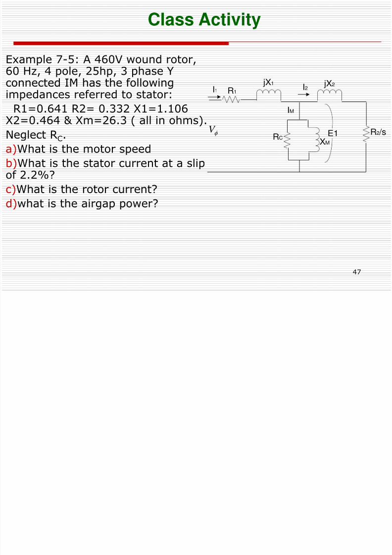
Class Activity
Example 7-5: A 460V wound rotor,
60 Hz, 4 pole, 25hp, 3 phase Yconnected IM has the followingimpedances referred to stator:
R1=0.641 R2= 0.332 X1=1.106X2=0.464 & Xm=26.3 ( all in ohms).
Neglect RC.a)What is the motor speed
b)What is the stator current at a slipof 2.2%?
c)What is the rotor current?
d)what is the airgap power?
I2
XM
IM
jX1
R1I1
RC
R2 /s
jX2
f V E1
Agenda
8/6/2019 Set5 Induction Motor Final
http://slidepdf.com/reader/full/set5-induction-motor-final 48/90
48
Agenda
• Review of Equivalent Circuit• Power & Torque of Induction Motor
- Losses & Power flow diagram- Power & torque- Separating rotor losses & power converted in IM
• Derivation of Torque-Speed Curve- Salient features of torque-speed curve- Variation of curve as function of rotor resistance
8/6/2019 Set5 Induction Motor Final
http://slidepdf.com/reader/full/set5-induction-motor-final 49/90
49
7.4 Power and Torque in Induction Machine
• Induction motor same like transformer.
• Input is 3-φ voltage & currents. • Output of transformer is electric power at
secondary winding.
• The secondary (rotor) of an induction machine is
shorted, therefore no electrical output forminduction machine instead mechanical output.
Mechanical Electrical
I d i M b l fl di
8/6/2019 Set5 Induction Motor Final
http://slidepdf.com/reader/full/set5-induction-motor-final 50/90
50
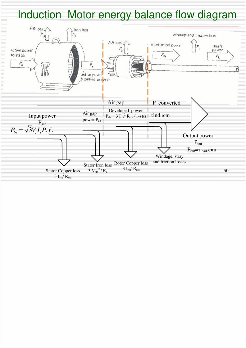
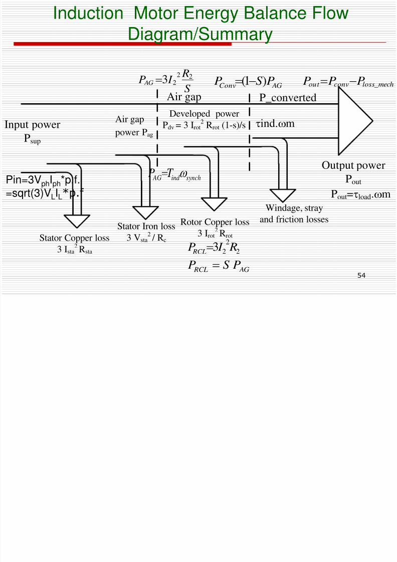
Induction Motor energy balance flow diagram
Input power
Psup
Stator Copper loss
3 Ista2 Rsta
Rotor Copper loss
3 Irot2 Rrot
Stator Iron loss
3 Vsta2 / Rc
Windage, stray
and friction losses
Output power
Pout
Air gap
power Pag
Developed power
Pdv = 3 Irot2 Rrot (1-s)/s
Air gap P_converted
ind.m
Pout=load.m
..3 f P I V P t t in
Equivalent Circuit
8/6/2019 Set5 Induction Motor Final
http://slidepdf.com/reader/full/set5-induction-motor-final 51/90
51
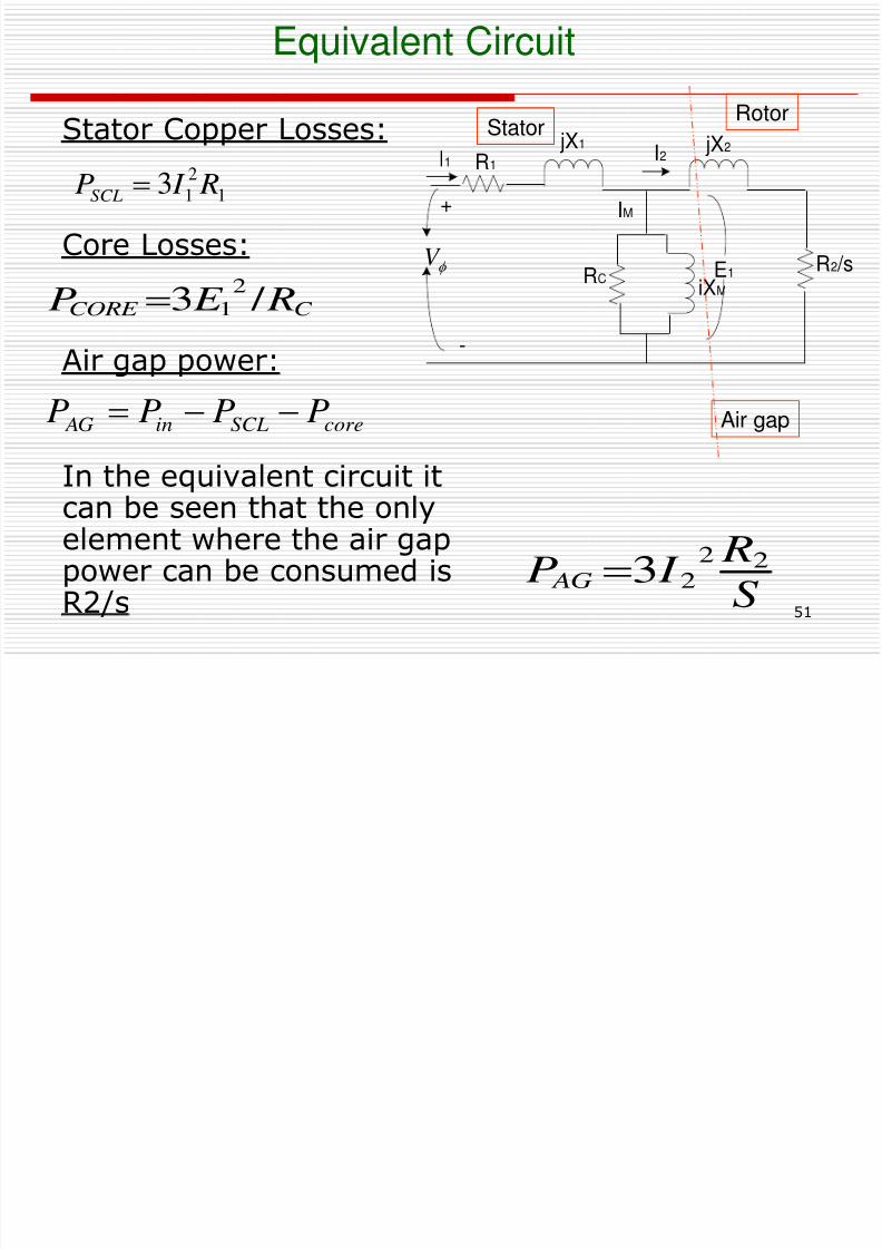
Equivalent Circuit
I2
E1
iXM
IM
jX1
R1I1
RCR2 /s
jX2
f V
+
-
Stator Copper Losses:
Core Losses:
Air gap power:
In the equivalent circuit itcan be seen that the onlyelement where the air gappower can be consumed isR2/s
1
2
13 R I PSCL
C CORE R E P/ 3
2
1
coreSCLin AG PPPP Air gap
RotorStator
S
R I P AG
22
23
Induction Motor: Power & Torque
8/6/2019 Set5 Induction Motor Final
http://slidepdf.com/reader/full/set5-induction-motor-final 52/90
52
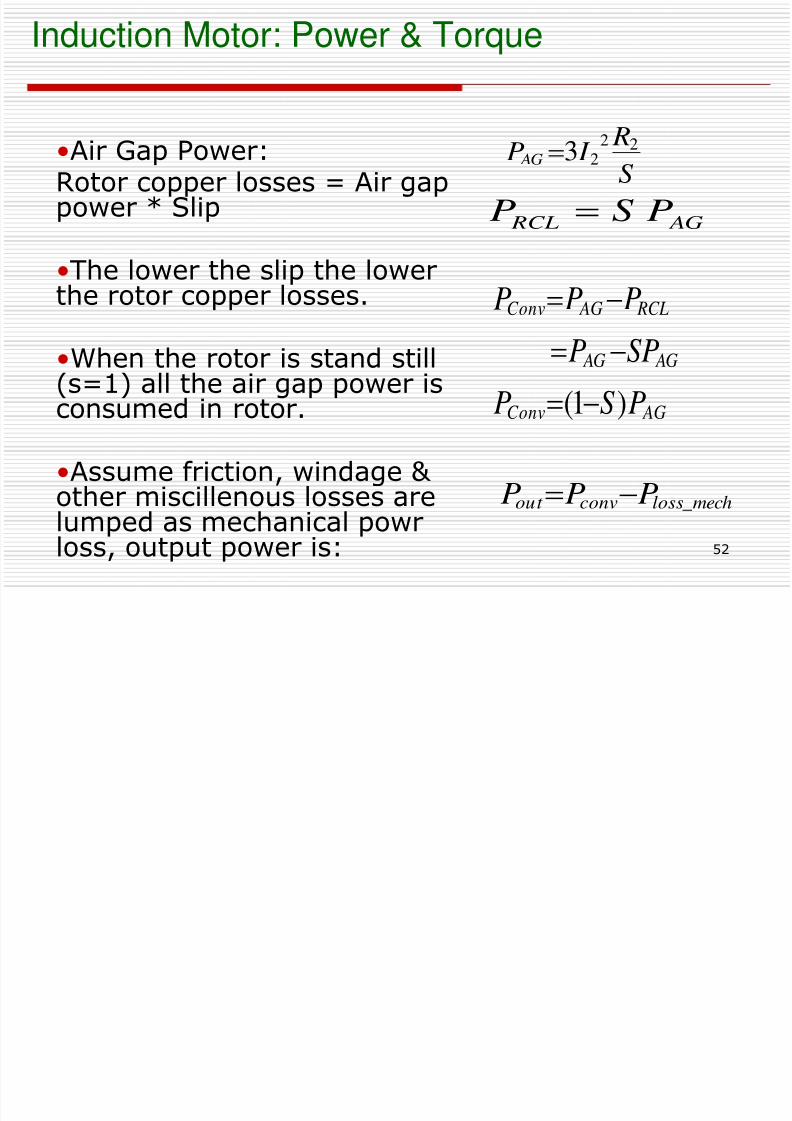
Induction Motor: Power & Torque
•Air Gap Power:Rotor copper losses = Air gappower * Slip
•The lower the slip the lowerthe rotor copper losses.
•When the rotor is stand still(s=1) all the air gap power is
consumed in rotor.
•Assume friction, windage & other miscillenous losses arelumped as mechanical powr
loss, output power is:
S R I P AG 2223
AG RCL PSP
AGConv
AG AG
RCL AGConv
PSP
SPP
PPP
)1(
mechlossconvout PPP _
Induction Motor: Power & Torque in
8/6/2019 Set5 Induction Motor Final
http://slidepdf.com/reader/full/set5-induction-motor-final 53/90
53
Induction Motor: Power & Torque inInduction Motor
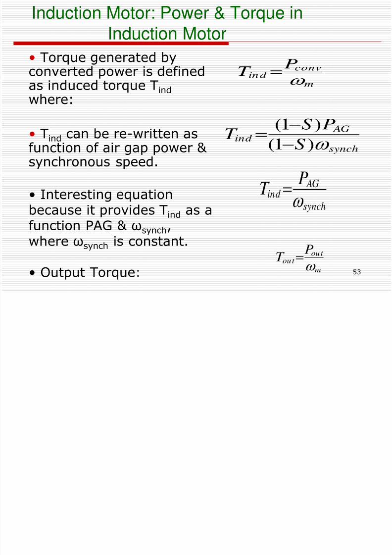
• Torque generated by
converted power is definedas induced torque Tind where:
• Tind
can be re-written asfunction of air gap power & synchronous speed.
• Interesting equation
because it provides Tind as afunction PAG & ωsynch,where ωsynch is constant.
• Output Torque:
synch
AGind
PT
synch
AG
ind S
PS
T )1(
)1(
m
convind
PT
m
out out
PT
Induction Motor Energy Balance Flow
8/6/2019 Set5 Induction Motor Final
http://slidepdf.com/reader/full/set5-induction-motor-final 54/90
54
Input power
Psup
Stator Copper loss
3 Ista2 Rsta
Rotor Copper loss
3 Irot2 Rrot
Stator Iron loss
3 Vsta2 / Rc
Windage, strayand friction losses
Output power
Pout
Air gap
power Pag
Developed power
Pdv = 3 Irot2
Rrot (1-s)/s
Air gap P_converted
ind.m
Pout=load.m
duct o oto e gy a a ce oDiagram/Summary
S R I P AG
2223
AG RCLPSP
AGConv PSP )1(
Pin=3VphIph*p.f. =sqrt(3)VLIL*p.f
2
2
23 R I P RCL
mechlossconvout PPP _
synchind AG T P
Equivalent Circuit

8/6/2019 Set5 Induction Motor Final
http://slidepdf.com/reader/full/set5-induction-motor-final 55/90
55
Equivalent Circuit
I2
E1
iXM
IM
jX1
R1I1
RCR2 /s
jX2
f V
+
-
Stator Copper Losses:
Core Losses:
Air gap power:
In the equivalent circuit itcan be seen that the onlyelement where the air gappower can be consumed isR2/s
1
2
13 R I PSCL
C C
CORE G E R
E
P
2
1
2
1
3
3
coreSCLin AG PPPP Air gap
RotorStator
S
R I P AG
22
23
E i l t Ci it ith R t L S t d
8/6/2019 Set5 Induction Motor Final
http://slidepdf.com/reader/full/set5-induction-motor-final 56/90
56
I2
E1
jXM
jX1
R1I1
RCR2(1-s)/s
jX2
R2
Coreloss
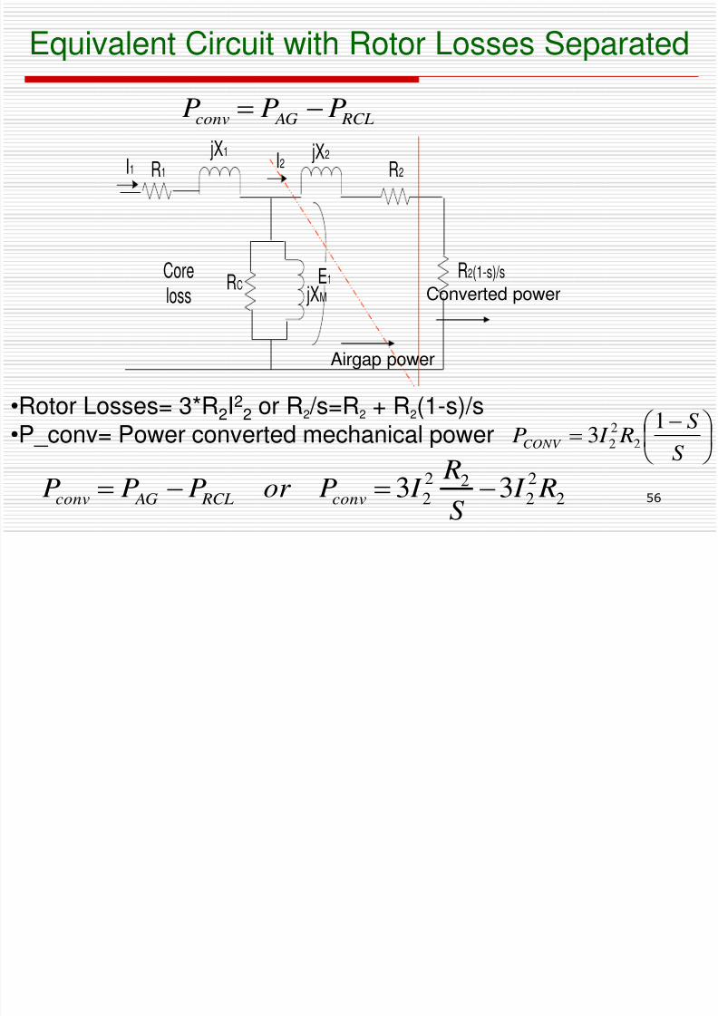
Equivalent Circuit with Rotor Losses Separated
S
S R I P
CONV
13 2
2
2
•Rotor Losses= 3*R2I22 or R2 /s=R2 + R2(1-s)/s
•P_conv= Power converted mechanical power
Converted power
Airgap power
2
2
222
2 33 R I S
R I Por PPP conv RCL AGconv
RCL AGconv PPP
Separating Rotor Copper Losses and Power
8/6/2019 Set5 Induction Motor Final
http://slidepdf.com/reader/full/set5-induction-motor-final 57/90
57
p g ppConverted in induction Machine
2
2
23 R I P RCL
S
S
R R
S R I P
R I S
R I P
PPP
conv
conv
conv
RCL AGconv
1
11
3
33
2
222
222
222
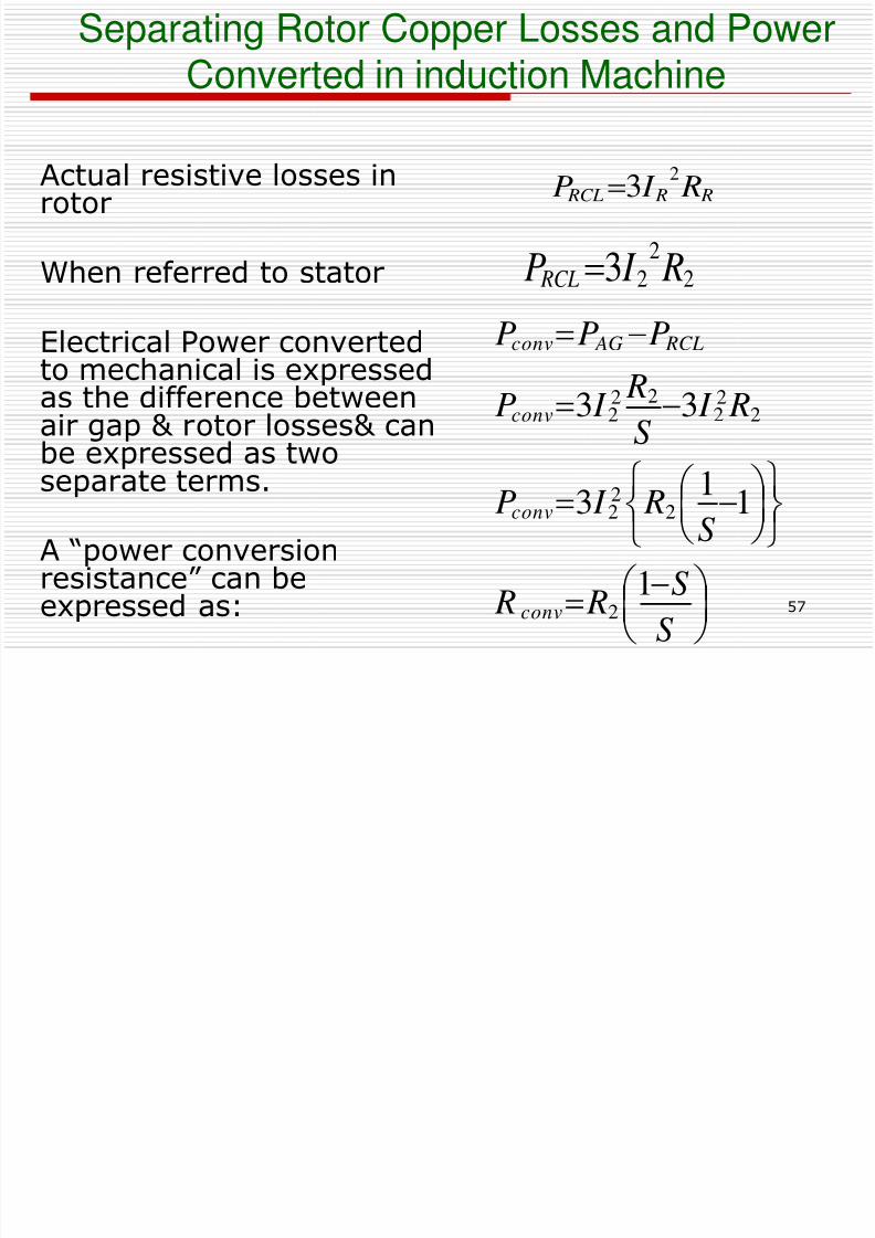
Actual resistive losses inrotor
When referred to stator
Electrical Power convertedto mechanical is expressedas the difference betweenair gap & rotor losses& can
be expressed as twoseparate terms.
A “power conversionresistance” can be
expressed as:
R R RCL R I P2
3
Per phase IM equivalent circuit with rotor
8/6/2019 Set5 Induction Motor Final
http://slidepdf.com/reader/full/set5-induction-motor-final 58/90
58
I2
E1
jXM
jX1
R1I1
RCR2(1-s)/s
jX2
R2
Core
loss
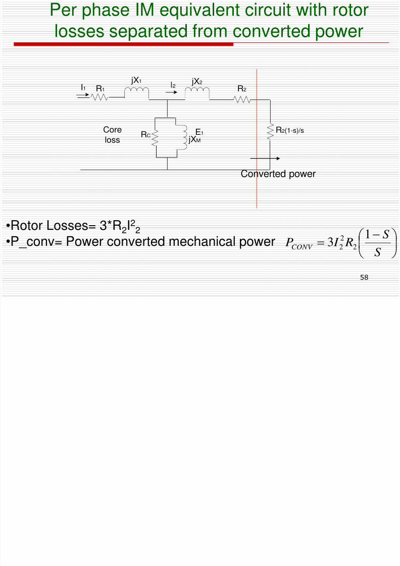
p qlosses separated from converted power
S
S R I PCONV
13 2
2
2
•Rotor Losses= 3*R2I22
•P_conv= Power converted mechanical power
Converted power
Equivalent Circuit
8/6/2019 Set5 Induction Motor Final
http://slidepdf.com/reader/full/set5-induction-motor-final 59/90
59
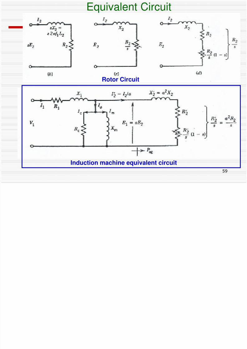
Rotor Circuit
Induction machine equivalent circuit
q
P Effi i d T /R i
8/6/2019 Set5 Induction Motor Final
http://slidepdf.com/reader/full/set5-induction-motor-final 60/90
60
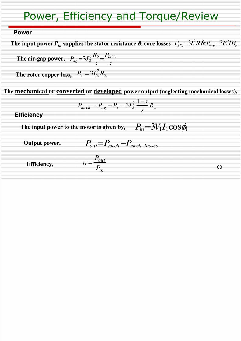
Power, Efficiency and Torque/Review
The input power Pin supplies the stator resistance & core losses ccoreSCL R E P R I P / 3&32
11
2
1 The air-gap power,
The rotor copper loss,
s
P
s
R I P RCL
ag 2223
2222 3 R I P
The mechanical or converted or developed power output (neglecting mechanical losses),
2222
13 R
s
s I PPP agmech
Power
Efficiency
The input power to the motor is given by, 111 cos3 f I V PinOutput power, lossesmechmechout PPP _
Efficiency,
in
out
P
P
St d d /L
8/6/2019 Set5 Induction Motor Final
http://slidepdf.com/reader/full/set5-induction-motor-final 61/90
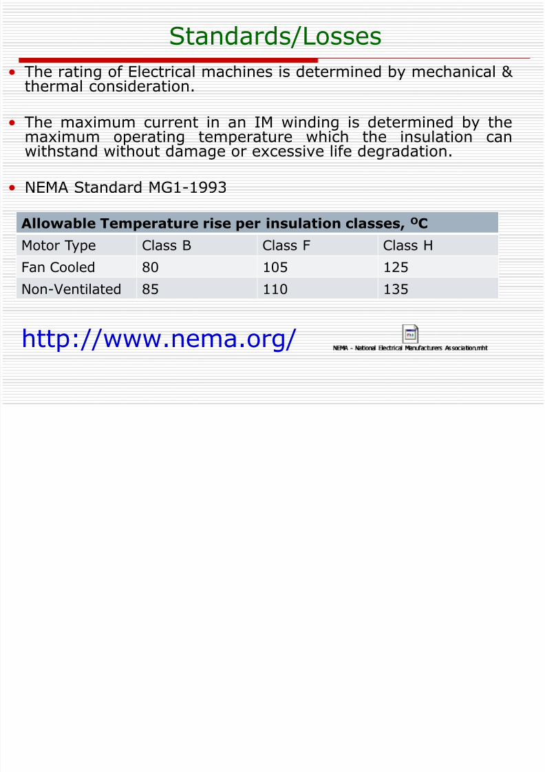
Standards/Losses
• The rating of Electrical machines is determined by mechanical & thermal consideration.
• The maximum current in an IM winding is determined by themaximum operating temperature which the insulation canwithstand without damage or excessive life degradation.
• NEMA Standard MG1-1993
Allowable Temperature rise per insulation classes, OC
Motor Type Class B Class F Class H
Fan Cooled 80 105 125
Non-Ventilated 85 110 135
http://www.nema.org/
8/6/2019 Set5 Induction Motor Final
http://slidepdf.com/reader/full/set5-induction-motor-final 62/90
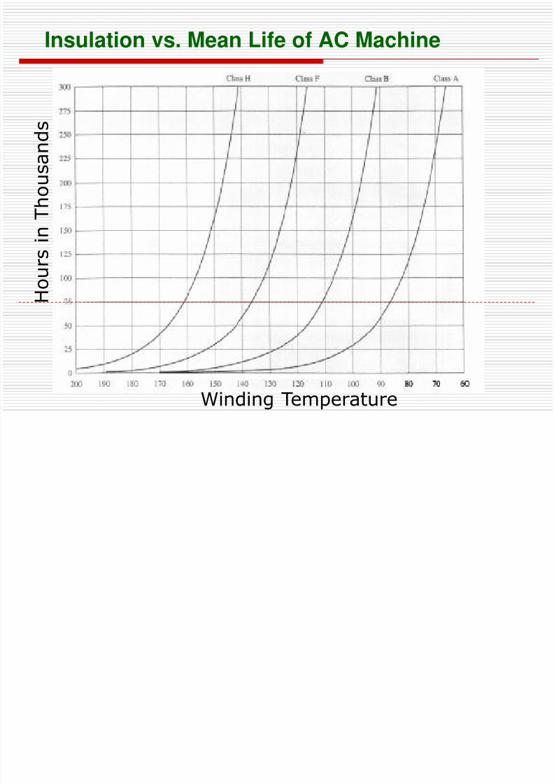
Insulation vs. Mean Life of AC Machine
H
o u r s
i n
T h
o u s a n d s
Winding Temperature
Class Activity
8/6/2019 Set5 Induction Motor Final
http://slidepdf.com/reader/full/set5-induction-motor-final 63/90
63
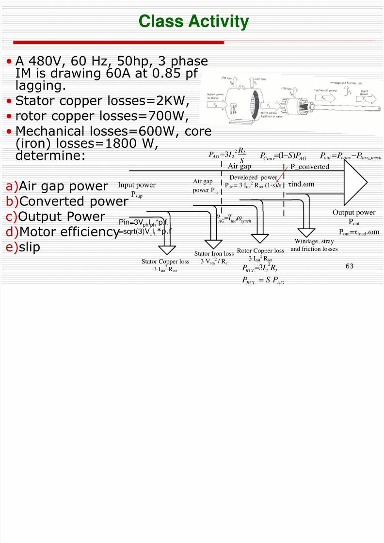
Class Activity
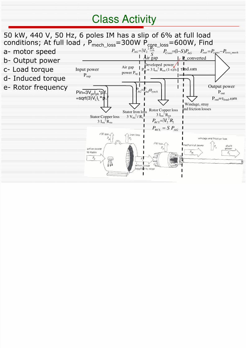
• A 480V, 60 Hz, 50hp, 3 phase
IM is drawing 60A at 0.85 pf lagging.
• Stator copper losses=2KW,• rotor copper losses=700W,• Mechanical losses=600W, core
(iron) losses=1800 W,determine:
a)Air gap power
b)Converted powerc)Output Powerd)Motor efficiencye)slip
Input power
Psup
Stator Copper loss
3 Ista
2 Rsta
Rotor Copper loss
3 Irot2 Rrot
Stator Iron loss
3 Vsta2 / Rc
Windage, stray
and friction losses
Output power
Pout
Air gap
power Pag
Developed power
Pdv = 3 Irot2 Rrot (1-s)/s
Air gap P_converted
ind.m
Pout=load.m
S
R I P AG
22
23
AG RCLPSP
AGConv PSP )1(
Pin=3VphIph*p.f.
=sqrt(3)VLIL*p.f
2
2
2
3 R I P RCL
mechlossconvout PPP _
synchind AG T P
Class Activity
8/6/2019 Set5 Induction Motor Final
http://slidepdf.com/reader/full/set5-induction-motor-final 64/90
64
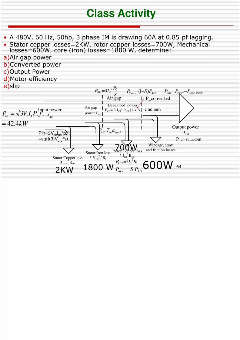
Class Activity
• A 480V, 60 Hz, 50hp, 3 phase IM is drawing 60A at 0.85 pf lagging.
• Stator copper losses=2KW, rotor copper losses=700W, Mechanicallosses=600W, core (iron) losses=1800 W, determine:a)Air gap powerb)Converted powerc)Output Powerd)Motor efficiency
e)slip
Input power
Psup
Stator Copper loss
3 Ista2Rsta
Rotor Copper loss
3 Irot2 Rrot
Stator Iron loss
3 Vsta2 / Rc
Windage, stray
and friction losses
Output powerPout
Air gap
power Pag
Developed power
Pdv = 3 Irot2 Rrot (1-s)/s
Air gap P_converted
ind.m
Pout=load.m
S
R I P AG22
23
AG RCL PSP
AGConv PSP )1(
Pin=3VphIph*p.f.
=sqrt(3)VLIL*p.f
2
2
23 R I P RCL
mechlossconvout PPP _
synchind AG T P
2KW
700W
600W1800 W
kW
f P I V Pt t in
4.42
..3
8/6/2019 Set5 Induction Motor Final
http://slidepdf.com/reader/full/set5-induction-motor-final 65/90
Outcomes
• Calculate power and torque in the induction motor as
function of motor operating point.• Calculate Converted power from equivalent circuit.
• Derive the torque-speed characteristics of the inductionmachine.
• Understand and predict the effect of various parameters
(rotor resistance, slip & input voltage) variation on the torquespeed characteristics.
65
7.5 Derivation of Induction Motor Induced
8/6/2019 Set5 Induction Motor Final
http://slidepdf.com/reader/full/set5-induction-motor-final 66/90
66
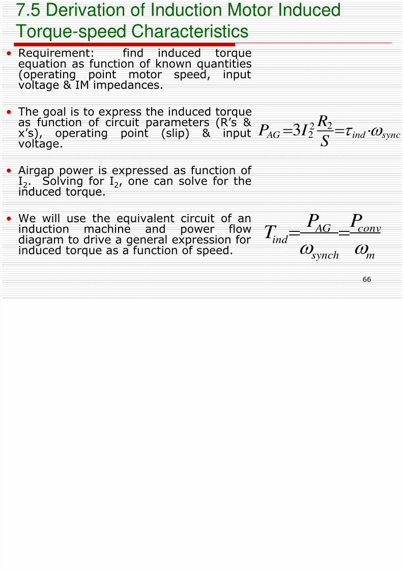
Torque-speed Characteristics• Requirement: find induced torque
equation as function of known quantities
(operating point motor speed, inputvoltage & IM impedances.
• The goal is to express the induced torqueas function of circuit parameters (R’s & x’s), operating point (slip) & input
voltage.
• Airgap power is expressed as function of I2. Solving for I2, one can solve for theinduced torque.
• We will use the equivalent circuit of aninduction machine and power flowdiagram to drive a general expression forinduced torque as a function of speed.
syncind AG
S
R I P 22
23
m
conv
synch
AGind
PPT
Derivation of Induction Motor Induced Torque-d Ch t i ti
8/6/2019 Set5 Induction Motor Final
http://slidepdf.com/reader/full/set5-induction-motor-final 67/90
67
speed Characteristics
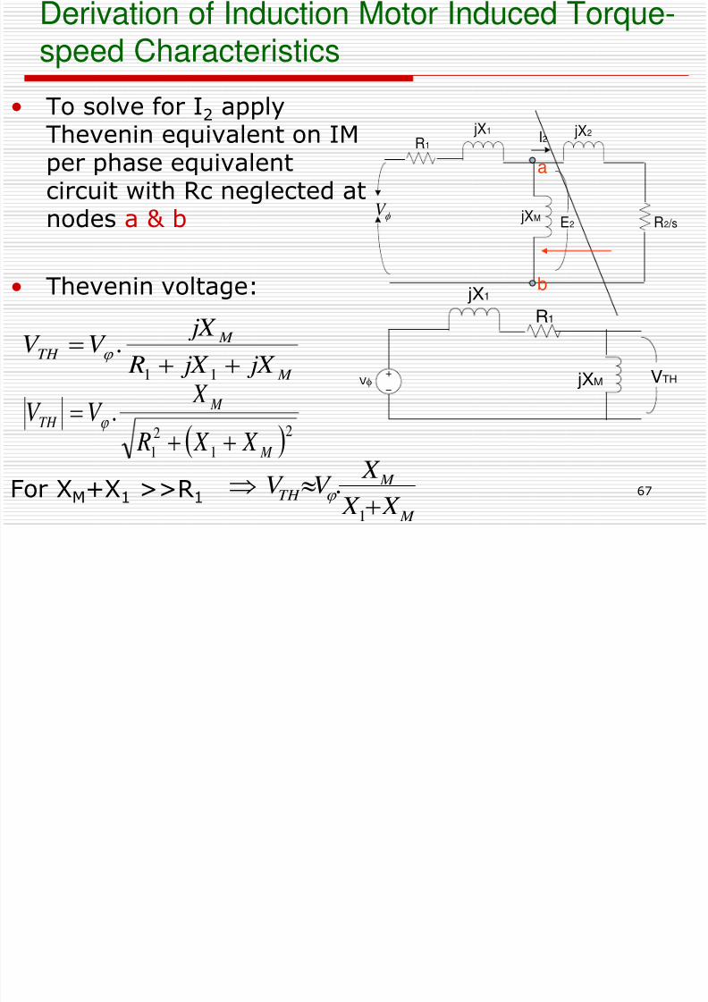
• To solve for I2 apply
Thevenin equivalent on IMper phase equivalentcircuit with Rc neglected atnodes a & b
• Thevenin voltage:
For XM+X
1>>R
1
R1
VTHVf
jX1
jXM
f V
I2
E2 jXM
jX1R1
R2 /s
jX2
M
M TH
jX jX R
jX V V
11
.
21
2
1
.
M
M
TH
X X R
X V V
a
b
M
M TH
X X
X V V
1
.
Derivation of Induction Motor Induced Torque-d Ch i i
8/6/2019 Set5 Induction Motor Final
http://slidepdf.com/reader/full/set5-induction-motor-final 68/90
68
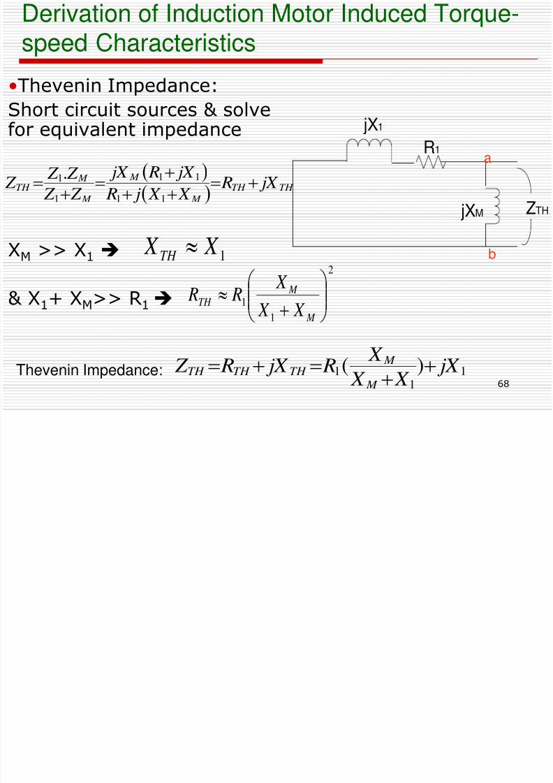
•Thevenin Impedance:
Short circuit sources & solvefor equivalent impedance
XM >> X1
& X1+ XM>> R1
R1
ZTH
jX1
jXM
speed Characteristics
TH TH
M
M
M
M TH jX R
X X j R
jX R jX
Z Z
Z Z Z
11
11
1
1.
2
1
1
M
M TH
X X
X
R R
1 X X TH
a
b
11
1 )( jX X X
X R jX R Z
M
M TH TH TH
Thevenin Impedance:
Derivation of Induction Motor Induced Torque-d Ch i i
8/6/2019 Set5 Induction Motor Final
http://slidepdf.com/reader/full/set5-induction-motor-final 69/90
69
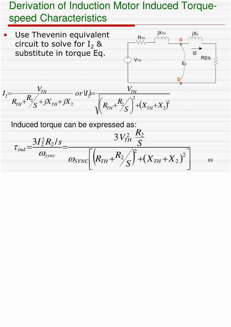
speed Characteristics
• Use Thevenin equivalent
circuit to solve for I2 & substitute in torque Eq.
22
2
2
2
22
2 ||
X X S
R R
V I or
jX jX S
R R
V I
TH TH
TH
TH TH
TH
VTH
E2
jXTH
RTH
jX2
x
x
R2/sI2
2
2
2
2
22
222
3 / 3
X X S
R R
S
RV
s R I
TH TH SYNC
TH
sync
ind
a
b
Induced torque can be expressed as:
8/6/2019 Set5 Induction Motor Final
http://slidepdf.com/reader/full/set5-induction-motor-final 70/90
8/6/2019 Set5 Induction Motor Final
http://slidepdf.com/reader/full/set5-induction-motor-final 71/90
71
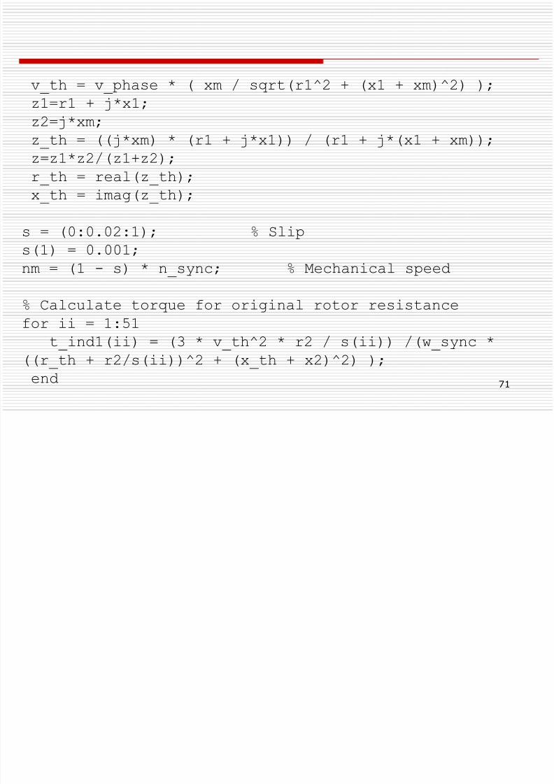
v_th = v_phase * ( xm / sqrt(r1^2 + (x1 + xm)^2) );
z1=r1 + j*x1;z2=j*xm;
z_th = ((j*xm) * (r1 + j*x1)) / (r1 + j*(x1 + xm));
z=z1*z2/(z1+z2);
r_th = real(z_th);
x_th = imag(z_th);
s = (0:0.02:1); % Slip
s(1) = 0.001;
nm = (1 - s) * n_sync; % Mechanical speed
% Calculate torque for original rotor resistance
for ii = 1:51
t_ind1(ii) = (3 * v_th^2 * r2 / s(ii)) /(w_sync *
((r_th + r2/s(ii))^2 + (x_th + x2)^2) );
end
S C
8/6/2019 Set5 Induction Motor Final
http://slidepdf.com/reader/full/set5-induction-motor-final 72/90
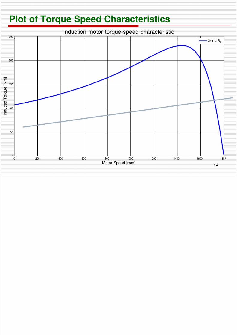
Plot of Torque Speed Characteristics
72
0 200 400 600 800 1000 1200 1400 1600 1800
50
100
150
200
250
Motor Speed [rpm]
I n d u c e d T o r q u e [ N m ]
Induction motor torque-speed characteristic
Original R2
IM Torque speed Characteristics
8/6/2019 Set5 Induction Motor Final
http://slidepdf.com/reader/full/set5-induction-motor-final 73/90
73
q p
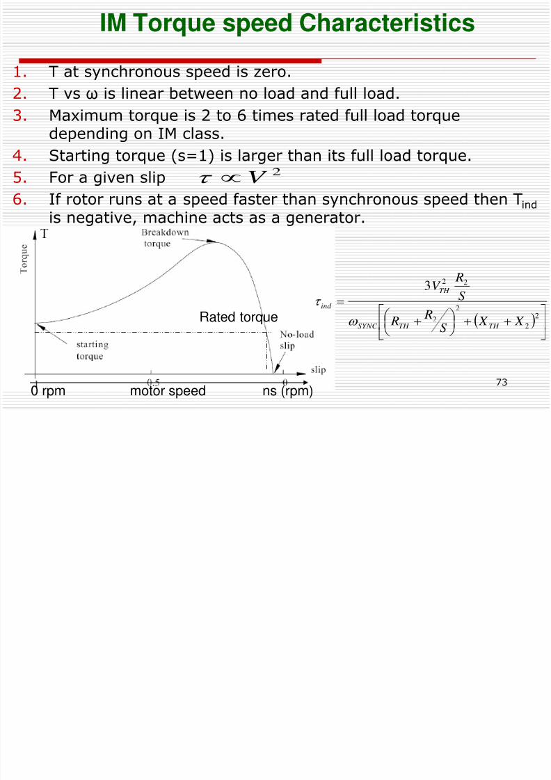
1. T at synchronous speed is zero.
2. T vs ω is linear between no load and full load.
3. Maximum torque is 2 to 6 times rated full load torquedepending on IM class.
4. Starting torque (s=1) is larger than its full load torque.
5. For a given slip
6. If rotor runs at a speed faster than synchronous speed then Tind is negative, machine acts as a generator.
2V
2
2
2
2
22 3
X X S
R R
S
RV
TH TH SYNC
TH
ind
Rated torque
0 rpm motor speed ns (rpm)
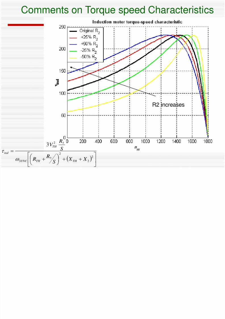
Comments on Torque speed Characteristics
8/6/2019 Set5 Induction Motor Final
http://slidepdf.com/reader/full/set5-induction-motor-final 74/90
R2 increases
q p
2
2
2
2
22 3
X X S
R
R
S
RV
TH TH SYNC
TH
ind
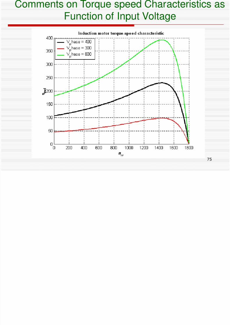
Comments on Torque speed Characteristics asFunction of Input Voltage
8/6/2019 Set5 Induction Motor Final
http://slidepdf.com/reader/full/set5-induction-motor-final 75/90
75
Function of Input Voltage
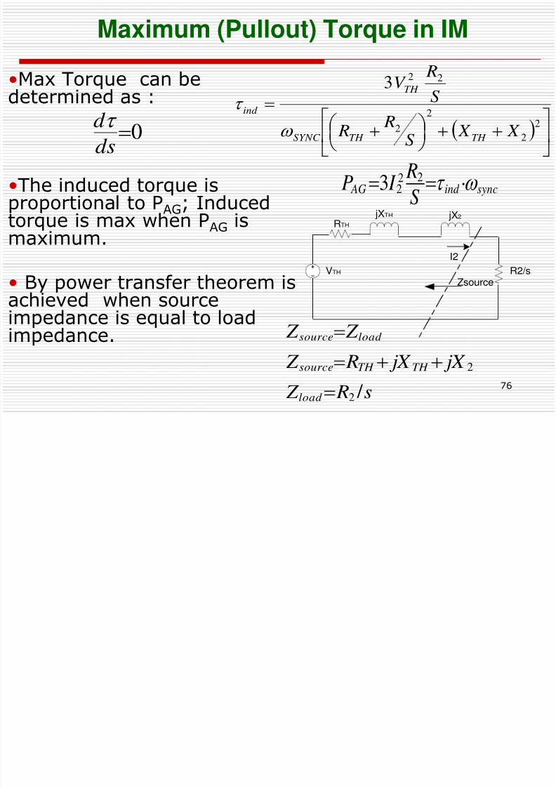
Maximum (Pullout) Torque in IM
8/6/2019 Set5 Induction Motor Final
http://slidepdf.com/reader/full/set5-induction-motor-final 76/90
76
( ) q
•Max Torque can be
determined as :
•The induced torque is
proportional to PAG; Inducedtorque is max when PAG ismaximum.
• By power transfer theorem is
achieved when sourceimpedance is equal to loadimpedance.
VTH
Zsource
jXTH
RTH
jX2
I2
R2/s
s R Z
jX jX R Z
Z Z
load
TH TH source
load source
/ 2
2
0ds
d
syncind AG
S
R I P 22
23
2
2
2
2
22 3
X X S
R R
S
RV
TH TH SYNC
TH
ind
Maximum Pull out Torque in Induction Machine
8/6/2019 Set5 Induction Motor Final
http://slidepdf.com/reader/full/set5-induction-motor-final 77/90
77
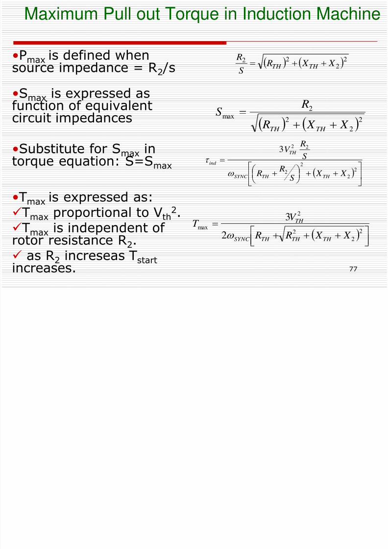
•Pmax is defined when
source impedance = R2 /s
•Smax is expressed asfunction of equivalentcircuit impedances
•Substitute for Smax intorque equation: S=Smax
•Tmax is expressed as:
Tmax proportional to Vth2.
Tmax is independent of rotor resistance R2. as R2 increseas Tstart increases.
22
22 X X R
S
RTH TH
2
2
2
2max
X X R
RS
TH TH
2
2
2
2
max
2
3
X X R R
V T
TH TH TH SYNC
TH
2
2
2
2
22 3
X X S
R R
S
RV
TH TH SYNC
TH
ind
Classes of Induction MachinesNEMA Standards
8/6/2019 Set5 Induction Motor Final
http://slidepdf.com/reader/full/set5-induction-motor-final 78/90
78
NEMA Standards
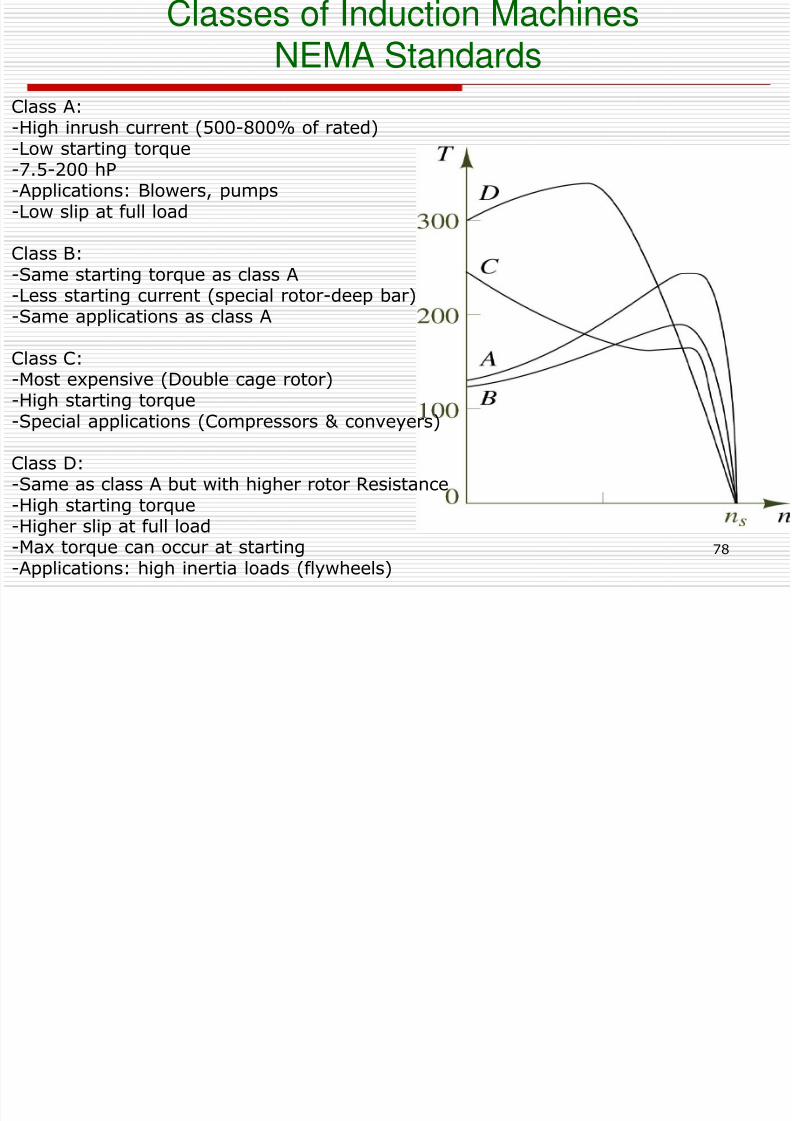
Class A:-High inrush current (500-800% of rated)
-Low starting torque-7.5-200 hP-Applications: Blowers, pumps-Low slip at full load
Class B:-Same starting torque as class A
-Less starting current (special rotor-deep bar)-Same applications as class A
Class C:-Most expensive (Double cage rotor)-High starting torque
-Special applications (Compressors & conveyers)
Class D:-Same as class A but with higher rotor Resistance-High starting torque-Higher slip at full load-Max torque can occur at starting
-Applications: high inertia loads (flywheels)
8/6/2019 Set5 Induction Motor Final
http://slidepdf.com/reader/full/set5-induction-motor-final 79/90
Review of Torque-speed characteristics
8/6/2019 Set5 Induction Motor Final
http://slidepdf.com/reader/full/set5-induction-motor-final 80/90
80
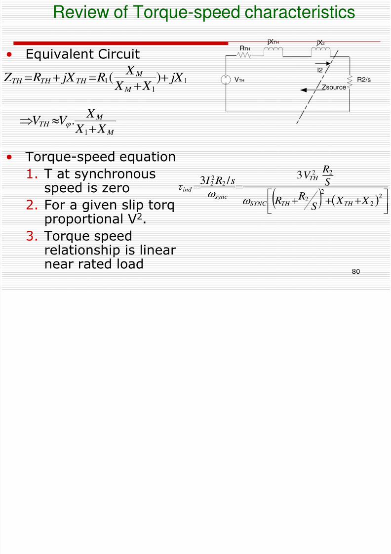
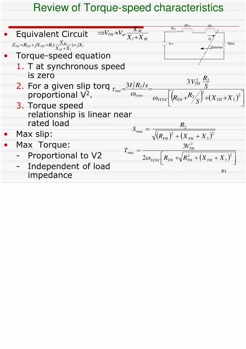
• Equivalent Circuit
• Torque-speed equation
1. T at synchronousspeed is zero
2. For a given slip torqproportional V2.
3. Torque speedrelationship is linearnear rated load
11
1 )( jX X X
X R jX RZ M
M TH TH TH
2
2
2
2
22
222
3 / 3
X X
S
R R
S
RV
s R I
TH TH SYNC
TH
sync
ind
VTH
Zsource
jXTH
RTH
jX2
I2
R2/s
M
M TH
X X
X V V
1
.
Review of Torque-speed characteristics
8/6/2019 Set5 Induction Motor Final
http://slidepdf.com/reader/full/set5-induction-motor-final 81/90
81
• Equivalent Circuit
• Torque-speed equation
1. T at synchronous speedis zero
2. For a given slip torqproportional V2.
3. Torque speedrelationship is linear nearrated load
• Max slip:• Max Torque:
- Proportional to V2
- Independent of load
impedance
111 )( jX X X
X
R jX R Z M
M
TH TH TH
2
2
22
22
222
3 / 3
X X S
R R
S
RV
s R I
TH TH SYNC
TH
syncind
VTH
Zsource
jXTH
RTH
jX2
I2
R2/s
M
M TH
X X
X V V
1
.
22
2
2
max X X R
RS
TH TH
2
2
2
2
max
2
3
X X R R
V T
TH TH TH SYNC
TH
Class Activity
8/6/2019 Set5 Induction Motor Final
http://slidepdf.com/reader/full/set5-induction-motor-final 82/90
82
Class Activity
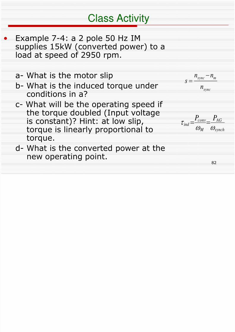
• Example 7-4: a 2 pole 50 Hz IM
supplies 15kW (converted power) to aload at speed of 2950 rpm.
a- What is the motor slip
b- What is the induced torque underconditions in a?
c- What will be the operating speed if the torque doubled (Input voltageis constant)? Hint: at low slip,torque is linearly proportional totorque.
d- What is the converted power at thenew operating point.
sync
msync
n
nns
synch
AG
M
conv
ind
PP
8/6/2019 Set5 Induction Motor Final
http://slidepdf.com/reader/full/set5-induction-motor-final 83/90
Class Activity
8/6/2019 Set5 Induction Motor Final
http://slidepdf.com/reader/full/set5-induction-motor-final 84/90
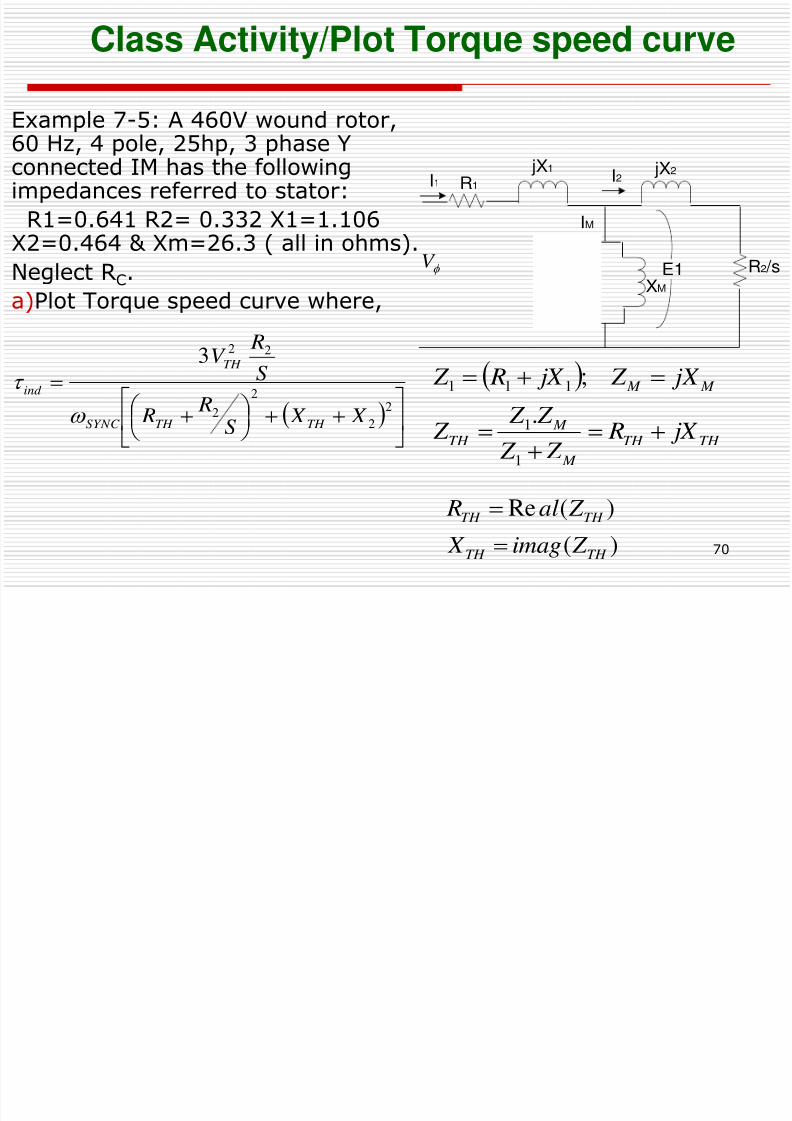
84
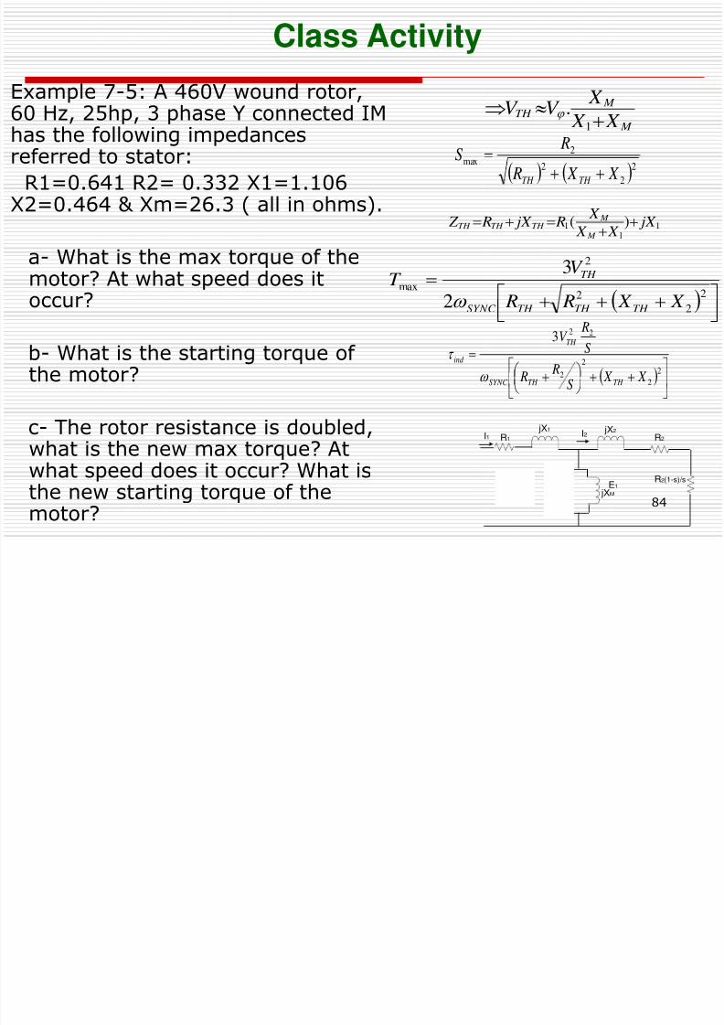
Example 7-5: A 460V wound rotor,60 Hz, 25hp, 3 phase Y connected IM
has the following impedancesreferred to stator:
R1=0.641 R2= 0.332 X1=1.106X2=0.464 & Xm=26.3 ( all in ohms).
a- What is the max torque of themotor? At what speed does itoccur?
b- What is the starting torque of the motor?
c- The rotor resistance is doubled,what is the new max torque? Atwhat speed does it occur? What isthe new starting torque of the
motor?
2
2
2
2
22 3
X X
S
R R
S
RV
TH TH SYNC
TH
ind
22
2
2max
X X R
RS
TH TH
2
2
2
2
max
2
3
X X R R
V T
TH TH TH SYNC
TH
11
1 )( jX X X
X R jX R Z
M
M TH TH TH
M
M TH
X X
X V V
1
.
I2
E1
jXM
jX1
R1I1
RC
R2(1-s)/s
jX2
R2
Core
loss
7 11 Determining Equivalent Circuit Parameters
8/6/2019 Set5 Induction Motor Final
http://slidepdf.com/reader/full/set5-induction-motor-final 85/90
85
7.11 Determining Equivalent Circuit Parameters
Equivalent Circuit Parameters for Induction Machine
• DC test
Calculate stator resistance
• No load Test
Approximate all rotational losses (core,windage, friction, misc)
• Locked rotor test
Approximate rotor & stator impedances.
DC Stator test
8/6/2019 Set5 Induction Motor Final
http://slidepdf.com/reader/full/set5-induction-motor-final 86/90
86
• Apply dc voltage across stator winding.
Calculate dc resistance of stator by applyingDC voltage across L-L winding
Measure dc Voltage & current
2Rstator= Vdc /Idc for Y connection
2Rstator /3=Vdc /Idc for delta connection
Locked Rotor Test
8/6/2019 Set5 Induction Motor Final
http://slidepdf.com/reader/full/set5-induction-motor-final 87/90
87
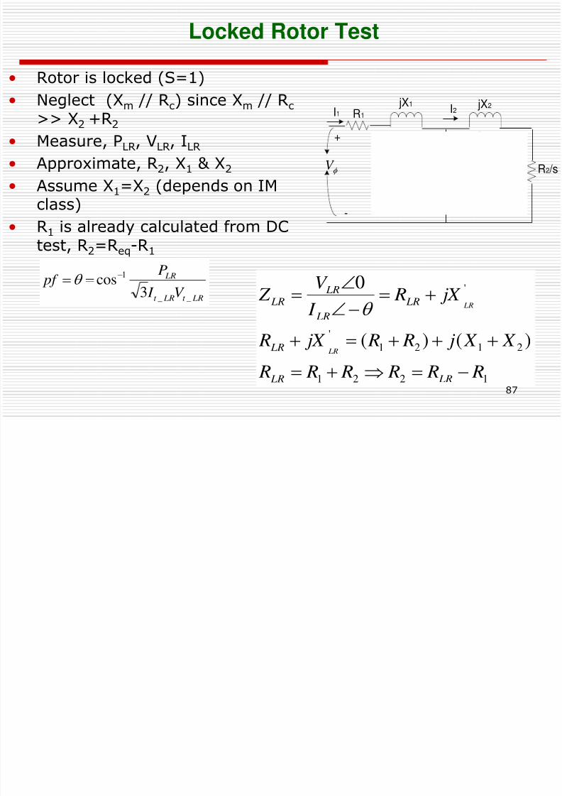
• Rotor is locked (S=1)
• Neglect (Xm // Rc) since Xm // Rc>> X2 +R2
• Measure, PLR, VLR, ILR
• Approximate, R2, X1 & X2
• Assume X1=X2 (depends on IM
class)
• R1 is already calculated from DCtest, R2=Req-R1
LRt LRt
LR
V I
P pf
__
1
3cos
1221
2121
'
'
)()(
0
R R R R R R
X X j R R jX R
jX R I
V Z
LR LR
LR
LR LR
LR
LR
LR
LR
I2
E1
iXM
IM
jX1
R1I1
RCR2 /s
jX2
f V
+
-
No load test
8/6/2019 Set5 Induction Motor Final
http://slidepdf.com/reader/full/set5-induction-motor-final 88/90
88
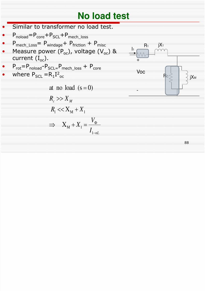
No load test• Similar to transformer no load test.
• Pnoload=Pcore+PSCL+Pmech_loss
• Pmech_Loss= Pwindage+ Pfriction + Pmisc
• Measure power (Poc), voltage (Voc) & current (Ioc).
• Prot=Pnoload-PSCL=Pmech_loss + Pcore
• where PSCL =R1I2oc jXM
jX1R1I1
RC
+
Voc
-
nL
M c
I
V X
X R
X R
1
1M
1M1
X
X
0)(s load noat
No load test
8/6/2019 Set5 Induction Motor Final
http://slidepdf.com/reader/full/set5-induction-motor-final 89/90
89
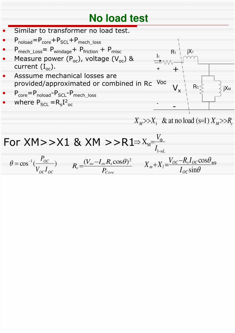
No load test• Similar to transformer no load test.
• Pnoload=Pcore+PSCL+Pmech_loss
• Pmech_Loss= Pwindage+ Pfriction + Pmisc
• Measure power (Poc), voltage (Voc) & current (Ioc).
• Asssume mechanical losses are
provided/approximated or combined in Rc• Pcore=Pnoload-PSCL-Pmech_loss
• where PSCL =RsI2oc
)(cos1
OC OC
OC
I V
P
sin
cos
OC
OC sOC
lm I
I RV
X X
Core
sococ
c P
R I V
R
2)cos(
jXM
jX1R1I1
RC
+
Voc
-
+
Vx
-
For XM>>X1 & XM >>R1nL
c M M
I
V
R X X X
1
M
1
X
1)(sloadnoat&
Conclusion
8/6/2019 Set5 Induction Motor Final
http://slidepdf.com/reader/full/set5-induction-motor-final 90/90
Conclusion
• Stator and rotor IM construction has been
discussed• Basic IM concept of operation has been detailed
• Construction of IM equivalent circuit has beenexplained
• Power & Torque of IM theory and flow has beenpresented
• IM Torque Speed Characteristics has been derived
• IM torque-speed curve as function of salientpoints and characteristics have been discussed
• Tests to determining IM equivalent circuitparameters have been studied.