Session U-08 AN AUTONOMOUS TRACKING …aseegsw.com/past Proceedings/U-08-Tucker.pdf · Within the...
15
Proceedings of the 2010 ASEE Gulf-Southwest Annual Conference, McNeese State University Copyright © 2010, American Society for Engineering Education 1 Session U-08 AN AUTONOMOUS TRACKING SYSTEM INTEGRATING UAV AND UGVS Christopher Tucker 1 , Juan Tafoyacabrera 1 , Christopher Montanez 1 , Remus Avram 1 , Matt Bauer 2 , Yufang Jin 1 1 Department of Electrical and Computer Engineering University of Texas at San Antonio 2 Department of Computer Science Arcadia University Abstract The purpose of our research is to integrate a system composed of an Unmanned Aerial vehicle (UAV) and an unmanned ground vehicle (UGV). The integrated heterogeneous system containing UAV and UGV could be used to scout areas which are not suitable for people to explore, and thus minimizing human risk. In our system, both the UAV and the UGV have a GPS unit to accurately localize the vehicle. The vehicles and the central control computer communicated with each other using a wireless transceiver. Through this wireless communication network and the GPS units, we have successfully coordinated the UAV and the UGV team and guided the UGV to follow the trajectory of the UAV. The novelty of this research lies in the fact that it has achieved the control, communication, and computation of the UAV and UGV, and further, integrated these heterogeneous systems into a real platform. Introduction Over the past decades, a great deal of research has been done in the field of unmanned vehicles that include ground air and sea. The first successful UAV in recorded history dates back to February of 1863 when a young man by the name of Charles Perley patented an unmanned aerial bomber 11 . This first UAV was simply a hot-air balloon which could carry a load of explosives and a timing mechanism for detonating. The invention of winged aircraft brought with it a more stable way of experimenting and deploying UAVs. UGVs have also greatly improved since the first major mobile robot was developed in the late 1960s by Stanford Research Institute 10 . There is some research currently being done in the area of UAV and UGV hybrid systems such as the “Griffon: a man portable UAV/UGV system”, however this is only proof of concept 8 . This research is motivated by the lacking of research on the integration of UAVs and UGVs. The aim of this research was to guide a UGV follow a UAV in a dynamic environment. Our previous research focused on trajectory planning of a UGV in a dynamic environment 14, 15 , cooperation of a UGV team in a dynamic environment 16 , modeling and control of UAV 12, 13, 17 , communication network of UGVs and UAVs 15 . These researches have set a solid foundation for us to further integrate a heterogeneous platform containing both UAV and UGV. In this research, we have selected a 10 feet blimp as our UAV, Arduino Mega as our UAV controller,
Transcript of Session U-08 AN AUTONOMOUS TRACKING …aseegsw.com/past Proceedings/U-08-Tucker.pdf · Within the...

Proceedings of the 2010 ASEE Gulf-Southwest Annual Conference, McNeese State University Copyright © 2010, American Society for Engineering Education
1
Session U-08
AN AUTONOMOUS TRACKING SYSTEM INTEGRATING UAV AND UGVS
Christopher Tucker1, Juan Tafoyacabrera1, Christopher Montanez1, Remus Avram1, Matt
Bauer2, Yufang Jin1 1Department of Electrical and Computer Engineering
University of Texas at San Antonio
2Department of Computer Science Arcadia University
Abstract The purpose of our research is to integrate a system composed of an Unmanned Aerial vehicle (UAV) and an unmanned ground vehicle (UGV). The integrated heterogeneous system containing UAV and UGV could be used to scout areas which are not suitable for people to explore, and thus minimizing human risk. In our system, both the UAV and the UGV have a GPS unit to accurately localize the vehicle. The vehicles and the central control computer communicated with each other using a wireless transceiver. Through this wireless communication network and the GPS units, we have successfully coordinated the UAV and the UGV team and guided the UGV to follow the trajectory of the UAV. The novelty of this research lies in the fact that it has achieved the control, communication, and computation of the UAV and UGV, and further, integrated these heterogeneous systems into a real platform. Introduction Over the past decades, a great deal of research has been done in the field of unmanned vehicles that include ground air and sea. The first successful UAV in recorded history dates back to February of 1863 when a young man by the name of Charles Perley patented an unmanned aerial bomber 11. This first UAV was simply a hot-air balloon which could carry a load of explosives and a timing mechanism for detonating. The invention of winged aircraft brought with it a more stable way of experimenting and deploying UAVs. UGVs have also greatly improved since the first major mobile robot was developed in the late 1960s by Stanford Research Institute 10. There is some research currently being done in the area of UAV and UGV hybrid systems such as the “Griffon: a man portable UAV/UGV system”, however this is only proof of concept8. This research is motivated by the lacking of research on the integration of UAVs and UGVs. The aim of this research was to guide a UGV follow a UAV in a dynamic environment. Our previous research focused on trajectory planning of a UGV in a dynamic environment14, 15, cooperation of a UGV team in a dynamic environment16, modeling and control of UAV12, 13, 17, communication network of UGVs and UAVs 15. These researches have set a solid foundation for us to further integrate a heterogeneous platform containing both UAV and UGV. In this research, we have selected a 10 feet blimp as our UAV, Arduino Mega as our UAV controller,

Pioneer 3In additiotransceivheterogengiven traj In this pathe hardwand UGVplatform. System
The integcommandmotors, hunit and then follo
Figure
Proceedings o
3-All Terrainon, we used
vers to achievneous system
ajectory with
aper, we wilware componV, respective.
m Structure
grated systemd is given toheading senssent to the Uowed the traj
1. Illustrate
of the 2010 ASCopyright ©
n (P3-AT) aGPS units m
ve the wirelem has achievh position err
l present thenents, the coely. Finally,
e and Com
m includes ao the UAV sors and miUGV via XBajectory of U
d above is th
SEE Gulf-South2010, America
as our UGV, mounted on ess communved the coopror of less th
e structure oontrol softwawe will dem
mponents
a UAV and and achievecrocontrolle
Bee transceivUAV in real t
he overall cosubsystem
hwest Annual Can Society for E
2
C++ as the the UAV an
nication betwperation betwhan one and a
f the integraare, and the
monstrate our
a UGV. Ined by the co
er. The localver. The UGtime.
ontrol systemms: UGV and
Conference, McEngineering E
programminnd UGV for
ween the UAween a UAVa half meters
ated system fcommunicar simulation
n a normal wontrol loop lization of th
GV obtained
m for the intd UAV
cNeese State UEducation
ng language r localization
AV and UGVV and UGV ws.
first. Then, wation protocon results and
working scenof the UAVhe UAV is sthe position
tegration be
University
to control Un and XBee V. The integwhile follow
we will introols for both Uillustrate the
nario, a trajeV system wisensed by a
n of the UAV
tween the tw
UGV. radio
grated wing a
oduce UAV e real
ectory th its GPS
V and
wo

UAV As a majwhich is steering transceivArduino detailed wflow char Indoor The indosystem u
Figure 2.and the LE
OutdoorThe outdavailable
Proceedings o
jor compone composed and propuls
ver. The conIDE langua
working schrt as follows
Gondola Soor gondola sses sonar to
. Displayed aboD and Driver u
r Gondola Sdoor Gondole. It uses GP
of the 2010 ASCopyright ©
ent in the inof necessarysion, sensorntrol and coage and em
heme of our s.
etup setup is useddetect its alt
ove is the Indoused for photo
Setup a Setup is u
PS to accurat
SEE Gulf-South2010, America
ntegrated sysy voltage re
rs for localiommunicatio
mbedded in UAV, we p
d when GPStitude from t
or Gondola Setracking, whic
used when thtely find its p
hwest Annual Can Society for E
3
stem, our UAegulation pazation (GPSon functionArduino M
presented the
S informationthe ground.
tup. Its main vch is used due t
he vehicle opposition with
Conference, McEngineering E
AV is a remarts, servos S), heading s of this U
Mega microce hardware c
n is not avail
variation is theto the low dep
perates outdh accuracy o
cNeese State UEducation
mote controllfor speed cosensor, and
UAV are procontroller. components
lable or is no
e Sonar which ipendability of t
doors and GPof <2.5 Mete
University
ed 10-foot bontrol, mixed communicogrammed uTo illustrateand the soft
ot required.
is used for altithe GPS unit in
PS informatiers.
blimp er for cation using e the tware
This
tude doors.
ion is
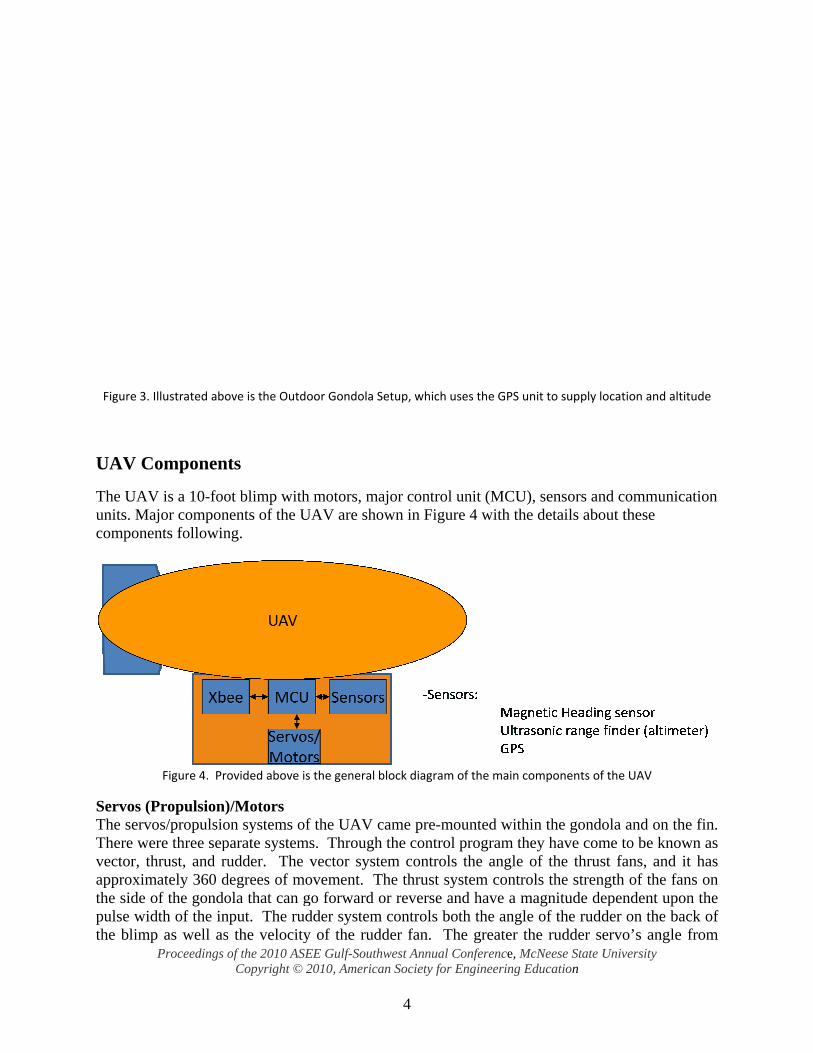
Figure 3.
UAV C
The UAVunits. Macompone
Servos (PThe servoThere wevector, thapproximthe side opulse widthe blimp
Proceedings o
Illustrated abo
Component
V is a 10-fooajor components followin
Figure 4. Pro
Propulsion)os/propulsioere three sephrust, and ru
mately 360 dof the gondodth of the inp as well as
of the 2010 ASCopyright ©
ove is the Outd
ts
ot blimp withnents of the Ung.
ovided above i
)/Motors on systems oparate systemudder. The
degrees of mola that can gnput. The rus the velocity
SEE Gulf-South2010, America
door Gondola S
h motors, maUAV are sho
is the general b
of the UAV cms. Through
vector systmovement. T
go forward oudder systemy of the rud
hwest Annual Can Society for E
4
Setup, which u
ajor control uown in Figur
block diagram
came pre-moh the control tem controlsThe thrust syor reverse an
m controls bodder fan. Th
Conference, McEngineering E
ses the GPS un
unit (MCU)re 4 with the
of the main co
ounted withiprogram the
s the angle oystem contrond have a moth the anglehe greater th
cNeese State UEducation
nit to supply lo
, sensors ande details abou
omponents of t
in the gondoey have comof the thrustols the streng
magnitude depe of the ruddhe rudder se
University
ocation and alti
d communicut these
the UAV
ola and on thme to be knowt fans, and igth of the fanpendent upo
der on the barvo’s angle
itude
cation
he fin. wn as it has ns on
on the ack of
from

Proceedings of the 2010 ASEE Gulf-Southwest Annual Conference, McNeese State University Copyright © 2010, American Society for Engineering Education
5
center, the greater the fan’s speed. All three were controlled with PWM (pulse-width modulation) signals. Sensors:
1) Heading Sensor:The Compass Module HMC6352 was used as the heading sensor for the UAV1. This item will be used in the final control system to determine proper guidance vectors. When placed within the gondola, the magnetic fields already present within the gondola affected the sensor and caused it to produce a different value. This was remedied with different placement on the UAV.
2) Sonar: The MaxSonar-EZ1 was used to provide altitude readings from the gondola to the control program9. By placing the sonar on the bottom of the gondola, the control system can retrieve its current altitude in inches ranging from 6 inches to 254 inches. A noted problem was that if anything obstructed or moved into the sonar’s area at an elevated height, it would produce erroneous altitude values.
3) GPS Module: The GPS module used on the UAV is a U-Blox5 GS4077. Its small form factor and light weight made it an ideal candidate to take part in our project. The module runs on 3.3 V @ 75mA and has a refresh rate of up to 4Hz with 50 satellite tracking channels. Initial testing of the module yielded satisfactory results with a time to fix (TTF) of less than one minute. The module’s main function is to relay positioning information from the UAV to the UGV. Xbee: Wireless Communication The Vehicle was equipped with an XBee6 transceiver module for wireless communication with the UGV. This wireless transceiver served as the principal link between the UAV and UGV. All positioning information coming from the UAV is sent through this link. Major Control Unit of UAV Within the prototype, the Arduino Mega board was chosen as the controller of the UAV system2. This board was chosen due to its ease of programming, multitude of documentation, and memory space. The characteristics of this board can be seen in Table 1. This board will also be sufficient for future progression into this research.
Table 1. Summary of Arduino Mega’s specifications Microcontroller ATmega1280 Operating Voltage 5V Input Voltage (recommended) 7‐12V Input Voltage (limits) 6‐20V Digital I/O Pins 54(of which 14 provide PWM output) Analog Input Pins 16 DC Current per I/O Pin 40 mA DC Current for 3.3V Pin 50 mA Flash Memory 128 KB of which 4 KB used by bootloader SRAM 8 KB EEPROM 4 KB Clock Speed 16 MHz

Proceedings of the 2010 ASEE Gulf-Southwest Annual Conference, McNeese State University Copyright © 2010, American Society for Engineering Education
6
Navigation software flowchart of UAV
The navigation system is broken down into several stages. The first stage initializes the settings within the microcontroller. Flowchart of the navigation system is shown in Figure 5. The code was written in a manner that the microcontroller is always listening for incoming commands. Once it detects am incoming command, it sorts it and determines which part of the control system the command belongs to. For example, if the incoming data is the ASCII character T, the code in the microcontroller runs the proper function referring to the thrust. Due to the sensitivity of the heading sensor, a calibration program has been written to minimize affects from external magnetic fields. When this process is initiated the commands are sent to sensor to calibrate it based on its documentation. After this has been completed a reading is taken at the four points: North, East, South, and West and stored in an array labeled headingval[]. From these stored values, the final value is interpolated using this equation:
slope = (float)(90/(headingval[m] ‐ headingval[m‐1])); newval = slope*(current‐headingval[m‐1])+((m‐1)*90);.
The slope of the equation is set by dividing the desired degree span by the actual degree span of one of the four quadrants. The m variable is the number of the quadrant based on a clockwise path, where North is 0 degrees, East is 90 degrees, South is 180 degrees, and West is 270 degrees. The current reading from the heading sensor is denoted as the variable current. The newval variable is the new degree value obtained after using a linear equation based on the previously obtained slope variable and the constant is based on 90 degree increments using the m value. One complication is the location of the transition from 359 degrees to 0 degrees. Whichever quadrant this is located in uses a slightly different equation. Seen below is used if this falls within the first quadrant.
difference = 360 ‐ headingval[0]; denominator = difference + headingval[1]; slope = (float)(90.00/denominator); if(temp<180){ newval = slope*(current)+ slope*(difference);} if(temp>270){ newval = slope*(current ‐ headingval[0]);}

Figure 5.flow chaon the firstring to This varidegree or90 degrethe normit is in thdegree di UAV/U
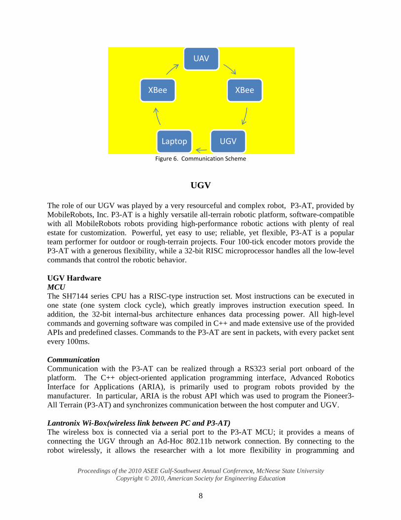
Communtransceivworks onrunning Mcomputer
Proceedings o
. Illustratesart, after initirst ASCII chthis desired
iation checkr if it is betwe span divid
mal value timhe second seifference tim
UGV comm
nication betwvers. The UGn the 802.1Matlab or anr is also achi
of the 2010 ASCopyright ©
s the pseudoialization, thharacter, initfunction
ks to see if tween the 270ded by the ov
mes the slope ction, it only
mes the slope
munication
ween the UGV can also1 protocol. ny program ieved using t
SEE Gulf-South2010, America
-code used ihe code seariates one of
the current h0 degree andverall value added to the
y needs the e.
n scheme
UAV and Uo be connect The UAV that has a sthe XBee wi
hwest Annual Can Society for E
7
in the main prches for inc
several func
heading readd the 360 degof the actuae overall degcurrent valu
UGV was aed to a laptocan also be
serial interfaireless transc
Conference, McEngineering E
portion of thoming data ctions while
ding is betwgree. Both ual span. If itgree span fo
ue minus the
achieved wiop using its we manually
ace. Commuceivers.
cNeese State UEducation
he code. Baon the seriapassing the
ween the 0 duse a slope set is in the firund in the se
e first stored
ith the use wireless boxcontrolled f
unication of
University
ased on the aal port, and b
remainder o
egree and thetup based orst section, itecond sectiovalue to fin
of XBee x (Wibox), wfrom a com
f the UAV w
above based of the
he 90 on the t uses on. If nd the
radio which
mputer with a
Proceedings of the 2010 ASEE Gulf-Southwest Annual Conference, McNeese State University Copyright © 2010, American Society for Engineering Education
8
Figure 6. Communication Scheme
UGV
The role of our UGV was played by a very resourceful and complex robot, P3-AT, provided by MobileRobots, Inc. P3-AT is a highly versatile all-terrain robotic platform, software-compatible with all MobileRobots robots providing high-performance robotic actions with plenty of real estate for customization. Powerful, yet easy to use; reliable, yet flexible, P3-AT is a popular team performer for outdoor or rough-terrain projects. Four 100-tick encoder motors provide the P3-AT with a generous flexibility, while a 32-bit RISC microprocessor handles all the low-level commands that control the robotic behavior. UGV Hardware MCU The SH7144 series CPU has a RISC-type instruction set. Most instructions can be executed in one state (one system clock cycle), which greatly improves instruction execution speed. In addition, the 32-bit internal-bus architecture enhances data processing power. All high-level commands and governing software was compiled in C++ and made extensive use of the provided APIs and predefined classes. Commands to the P3-AT are sent in packets, with every packet sent every 100ms. Communication Communication with the P3-AT can be realized through a RS323 serial port onboard of the platform. The C++ object-oriented application programming interface, Advanced Robotics Interface for Applications (ARIA), is primarily used to program robots provided by the manufacturer. In particular, ARIA is the robust API which was used to program the Pioneer3-All Terrain (P3-AT) and synchronizes communication between the host computer and UGV. Lantronix Wi-Box(wireless link between PC and P3-AT) The wireless box is connected via a serial port to the P3-AT MCU; it provides a means of connecting the UGV through an Ad-Hoc 802.11b network connection. By connecting to the robot wirelessly, it allows the researcher with a lot more flexibility in programming and
UAV
XBee
UGVLaptop
XBee

Proceedings of the 2010 ASEE Gulf-Southwest Annual Conference, McNeese State University Copyright © 2010, American Society for Engineering Education
9
maneuvering the P3-AT. The Wi-Box allows the UGV to be controlled by any computer or laptop configured with a wireless network device. Navigation For navigation the UGV is equipped with a 3-axis compass, or magnetometer, that has the ability to produce the UGV’s current absolute heading. In addition, the compass can also output other useful information such as pitch, roll, and temperature. The main component for UGV navigation is the robots onboard Novatel GPS Unit. The particular Novatel model being used has as an accuracy of less than one meter. The GPS and compass will be used in outdoor situations where the desired objective is for the UGV to be able to follow the UAV. Sonar Sensor In order to enhance the robots behavior a few external devices were added to the platform: Sonar sensors (16 sensors to offer an immediate preview of the surrounding environment) These sensors are radially distributed around the robot and they confer a decent initial scan of the perimeter. However, because of their position on the robot and the different possible refraction angles and the divergence of the sonar reading vectors the sonar sensor array is not best fitted for our purpose. Figure 7 shows the sonar setup at the front of the P3-AT:
Using the Law of sines we can determine the maximal error between any two adjacent readings. i.e.: The front of the robot two readings hold a 1,73 m error between their readings at a distance of 5 meters ahead of the robot.
sin 20 5
sin 80 1.73
LASER sensor(offers a better scanning accuracy, 360 readings / 180 degree span) Unlike the Sonar Sensor Array, the Laser system offers a 180 degree vision, with a reading every 0.5 degrees and a maximal length of vision of 35 meters. Using the same law of sines at 35m ahead of the robot our error is now only 0.3m and 0.043m at 5 meters ahead of the robot, thus providing us with much higher accuracy.
Figure 7 Displaying the front sonar array.

Proceedings of the 2010 ASEE Gulf-Southwest Annual Conference, McNeese State University Copyright © 2010, American Society for Engineering Education
10
Various experiments have shown and proved the accuracy of the Laser. In Figure 8 you can observe, how the robot detects the two static objects an their physical values:
Figure 8
UGV Software
As stated, in addition to the hardware by MobileRobots, Inc. application programming interfaces (API) were also provided. In particular the API of interest is Advanced Robotics Interface for Applications (ARIA). This API allows the programmer to easily interface with the P3-AT and program desired responses. The programmed responses can be simple programs, such as programs that send a series of direct movement commands. On the other hand, ARIA has the capability to create fairly complex programs that invoke many actions, or behaviors. A mixture of actions can result in high-level and intelligent behaviors. Due to the two types of environment (indoors vs. outdoors) two different following procedures have been approached. While indoors, a camera mounted on the UGV will keep track of the UAV and by the means of image processing, it would be able to determine the UAV movement and compute its new coordinates. Indoor Navigation As stated in the introduction the goal of the project is for the UGV to follow a specific path, predetermined by a freely moving unmanned aerial vehicle. In order to achieve our goal several navigational steps are required:
− provide P3-AT with enough knowledge about its surrounding environment; − establish communication with UAV; − develop obstacle avoidance and path planning algorithm. Add previous research result
references
Actual Size
Robot Reading
Error (in mm)
70.7106 64.9 5.810618.3847 20.2 1.8152

All the aeither sim Knowledlaser devUsing thedynamic has been move to t The prooMATLAgovernin OutdoorOnce thebecomes take the Uimage prUAV and The softwto the UAfor the U
External every secprogram UAV. onboard
Proceedings o
above mentiomultaneously
dge about thvice offers ae laser the teor static obachieved w
this position
of of concepAB image png software.
r Navigatione UAV and
less practicaUAV out of rocessing obd UGV.
ware is able AV’s curren
UGV.
to the UGVcond to a locreads this lAfter retrievGPS system
Read Uloca
Sendlocat
UG
Readcurreloca
of the 2010 ASCopyright ©
oned steps hy or consecu
he environma 180 degreeeam obtainedstacles, as w
with the UAVn, in the optim
pt of this meprocessing
n UGV followal due to a d
f the viewingbsolete. To
to track andnt location.
Figure
V GPS followcation that clocation andving the UA
m, and the UG
UAV GPS ation
d UAV ion to GV
d UGV nt GPS ation
SEE Gulf-South2010, America
have been autively depen
ment has beee span and ud critical inf
well as their V and a positmal amount
ethod has becode and i
wing systemdecrease in syg angle for thsolve this p
d follow the UThe followi
9 Overview of
wing softwarcan be read bd takes in asAV GPS CoGV’s current
Calculatdista
Calculaheacha
Read cohea
hwest Annual Can Society for E
11
ttained by thnding on thei
en achieved up to 35m rformation abphysical chation was obtof time, whi
een accompliinter-proces
m moves fromystem stabilhe UGV the
problem a G
UAV by coming flowchar
f UGV GPS fol
re, UAV cooby the GPS s variables tordinates tht heading is
te travel ance
ate the ding ange
ompass ding
Conference, McEngineering E
he means ofir priority.
via the LAradius with
bout the enviaracteristics.tained, the Uile avoiding
ished only ising comm
m indoors toity. In particreby making
GPS system w
mparing the rt describes
llowing progra
ordinates aresoftware. C
the current lhe UGV’s coread from th
Chthres
ChangUGV’s h
Move Udesdista
cNeese State UEducation
f blocks of
ASER readina reading evronment, su. Once a com
UGVs primaany obstacle
n simulationmunication w
o outdoors icular, wind gg the methodwill also be
UGV’s currthe GPS fo
am.
e written appConsequentlylongitude anoordinates ahe onboard c
eck sholds
ge the heading
UGV the sired ance
University
software run
ngs. The onbvery half dech as presenmmunicationarily scope wes on the wa
n manner uswith the P3
image procegusts can qud of followinrunning on
rent GPS locllowing soft
proximately y, the UGV
nd latitude oare read fromcompass.
nning
board egree. nce of n link
was to ay.
sing a 3-AT
essing uickly ng by both
cation tware
once GPS
of the m the

After reathem froaccompliArMapGcoordinat Once therobot is tcalculate
Figure 10 M
The desivectors (E
Assuminthis case,
At this pcan be cafor the diby:
Finally, These thr
Proceedings o
ading coordinom longitudished by a
GPSCoords utes that are s
e variables ato travel are
ed are display
Model used to
ired headingEquation 1).
ng that the he, 0
point all the valculated. Thistance betw
the calculatreshold limi
of the 2010 ASCopyright ©
nates, it is nde-latitude-a
function frused was conscaled in mil
are in Cartecalculated.
yed below in
determine the
g is calculate.
eading will a. Vector v i
variables arehe distance t
ween two poin
ted distanceits were imp
SEE Gulf-South2010, America
necessary to altitude (LLrom ARIA’nvertLLA2Mllimeters.
esian coordinThe model
n Figure 10.
desired headin
ed by apply
· cos
always be reis a variable
e known andthat the UGVnts. In this c
e and desireplemented du
hwest Annual Can Society for E
12
apply a tranLA) a local
s ArMapGPMapCoords.
nates the deof the system
ng and distance
ying the form
s | || |
lative to norand is show
d, solving foV should travcase, the dist
ed heading ue to the fac
Conference, McEngineering E
nsformation l X, Y coPSCoords c The result
esired headinm used and
e to travel.
mula for fin
1
rth, vector vwn in equatio
or theta, the vel is calcultance that the
are comparct that the G
cNeese State UEducation
to the coordoordinate syclass. The of this func
ng and the the variable
nding the an
was treated on 2.
2
desired headated by apple UGV shou
3
red against GPS typically
University
dinates to coystem. Th
function wction is Cart
distance thaes that need
ngle between
as a constan
ding of the Ulying the foruld travel is g
threshold liy has an err
onvert his is within tesian
at the to be
n two
nt. In
UGV rmula given
imits. ror of

Proceedings of the 2010 ASEE Gulf-Southwest Annual Conference, McNeese State University Copyright © 2010, American Society for Engineering Education
13
about ±1 meter. Finally, if the conditions were met, the robot was given the command to turn towards the calculated direction of the UAV . In order to make the robot turn towards the desired heading the angle between the current heading and desired heading had to be calculated. The robot's current heading was known by reading the UGV's onboard compass. The change of heading was equivalent to the desired heading less the current heading. The UGV was then given a command to change its heading by the previously calculated value. After this rotational command was complete, then the command was sent to travel the previously calculated distance. This results in continuous following of the UAV if the entire process is repeatedly looped. For this particular application the refresh rates of both the UAV and UGV GPS systems was about one second. For this reason, the entire previously discussed following scheme is updated approximately every second.
System Integration Integration of the UAV and UGV systems as one hybrid platform was made possible by combining all components of the two systems. The MCUs were in charge of controlling the individual parts in each vehicle. The Arduino Mega microcontroller served as the central processing unit for the UAV. Its tasks were to control the servos, get sensor readings and relay information to the UGV. Communication was the link that tied the two systems together. The XBee wireless transceiver modules were used to send and receive data between the two vehicles. During testing, we found out the transceivers were able to communicate at a distance of about 100 meters and provided reliable data delivery. The UAV could be controlled using a computer to send serial ASCII characters through the wireless network. Navigation was one of the crucial elements for the success of the system. The use of GPS allowed for accurate positioning of down to less than two meters for the UAV. The UAV was able to send positioning data down to the UGV. The UGV received the data and, by applying the previously discussed UGV GPS following program, the UGV was successfully able to travel to the UAV’s current position.
Conclusion
The studies of UAV and UGV have been carried for a long time, but their integration is a fairly new idea. This project progresses through the integration of these two heterogeneous systems into one overall system which will have multiple possibilities from communication radius expansion to search and rescue. Found through this project are various methods of accomplishing this task with the use of a certain aircraft and mobile robot along with various components. We set out to create a hybrid system composed of two distinct vehicles. Two very promising tracking methods were presented to us at the beginning of our research. GPS tracking was chosen over object tracking. GPS tracking gave us the advantage of covering greater distances and was easier to interface.

Proceedings of the 2010 ASEE Gulf-Southwest Annual Conference, McNeese State University Copyright © 2010, American Society for Engineering Education
14
References
1. Compass Module - HMC6352. Sparkfun Electronics. [Online] http://www.sparkfun.com/commerce/product_info.php?products_id=7915.
2. Arduino Mega. Arduino. [Online] http://arduino.cc/en/Main/ArduinoBoardMega. 3. ActivMedia Robotics, LLC. CMPE 300 ARIA Lab Manual. 2002. 4. MobileRobots, Inc. MobileRobots Advanced Robotics Interface for Applications (ARIA) Developer's
Reference Manual. Amherst : s.n., 2009. 5. Pioneer 3 Operations Manual. Amhurst : s.n., July 3007. 6. XBee/XBee-PRO OEM RF Modules. Lindon : maxtream, 2006. 7. Yen, Chris. GPS module Spec. s.l. : S.P.K. Electronics, 2009. 8. Griffon: A Man-Prtable Hybrid UGV/UAV. Yamauchi, Brian. Burlington : s.n., 2004. 9. LV-MaxSonar-EZ1 High Performance Sonar Range Finder. s.l. : MaxBotix inc., 2007. 10. UGV HISTORY 101: A Brief History of UGV Development Efforts. Gage, Douglas W. 3, s.l. : Unmanned
Systems Magazine, 1995, Vol. 13. 11. SPIES THAT FLY. PBS. [Online] PBS, November 2002. [Cited: January 1, 2009.]
http://www.pbs.org/wgbh/nova/spiesfly/uavs.html 12. Sylvester Meighan, Nick Grady, Chunjiang Qian, "Inertial Measurement Unit of System Identification of
an Unmanned Aerial Vehicle", Research Poster in Society of Mexican American Engineers and Scientists International Symposium, Albuquerque, New Mexico on October 24-27, 2007.
13. R. Jia, M. Frye, and C. Qian, "Flight Control for an Airship System Based on Particle Swarm Optimization Technique", Proceeding of IEEE Multi-conference on Systems and Control, Sep 2008, San Antonio, US.
14. Marcos Bird, Carlos Quiroz, and Yufang Jin, "Lead-follower Control Scheme for Unmanned Ground Vehicles in an Unknown Environmen", Abstracts of IEEE Multi-conference on Systems and Control, Sep 2008, San Antonio, US.
15. Carlos Quioz, Marcos Birs, Chuong Khuc, Yufang Jin, "Integration of Heterogeneous Unmanned Ground Vehicles with Synchronized Communication", Undergraduate Student Technical Paper Competition at ASEE-GSW conference, March 18-20, 2009
16. Siyao Gu, Marcos Bird, Scott Timme, Yufang Jin, "Formation Control of Unmanned Ground Vehicles Using Visual Feedback", Proceeding of ASEE-GSW conference, March 18-20, 2009.
17. Zana Coulibaly, Luis Alonso, Benito Garcia,Hervie Martin, Yufang Jin, "Controller Design and Hardware implementation of airship", Abstract of IEEE Multi-conference on Systems and Control, Sep 2008, San Antonio, US.
CHRISTOPHER TUCKER Chris will receive his Bachelors of Science in Electrical Engineering from the University of Texas at San Antonio at the accumulation of the Spring 2010 semester focusing on control systems. His research interests include design and development of embedded systems and robotics. JUAN TAFOYACABRERA Mr. Tafoyacabrera is currently a senior Electrical Engineering student at the University of Texas in An Antonio. His research interests include control systems for Automated Unmanned Aerial Vehicles. CHRISTOPHER MONTANEZ Christopher received his Bachelors of Science in Electrical Engineering from the University of Texas at San Antonio with a concentration in Computer Engineering. He is currently pursuing his Master of Science Degree in Electrical Engineering at the University of Texas at San Antonio. His research interests include digital system design, embedded systems design and programming, and C++ programming. REMUS AVRAM Remus received a Bachelors of Science in Electrical Engineering from the University of Texas at San Antonio with concentration in Computer Engineering. His interest is in embedded software solutions, digital system design and various electrical design procedures.

Proceedings of the 2010 ASEE Gulf-Southwest Annual Conference, McNeese State University Copyright © 2010, American Society for Engineering Education
15
Matt Bauer Matt received a Bachelors of Science in Computer Science from Arcadia University. He is applying for graduate schools to continue this research now. YUFANG JIN Dr. Jin currently serves as an Assistant Professor of Electrical Engineering at the University of Texas at San Antonio. Her research interests include robust adaptive control design for nonlinear systems, vision based control for mobile robots, synchronization and parameter estimation of chaotic systems, and observer design for nonlinear systems.