Session 8 Maxwell’s Equations - University of Hull
37
1 Session 8 Maxwell’s Equations Emma Bunce Physics Innovations Centre for Excellence in Learning and Teaching CETL (Leicester) Department of Physics and Astronomy University of Leicester
Transcript of Session 8 Maxwell’s Equations - University of Hull
1
Session 8
Maxwell’s Equations
Emma Bunce
Physics Innovations Centre
for Excellence in Learning and Teaching
CETL (Leicester)
Department of Physics and Astronomy
University of Leicester

2
Contents
Welcome .................................................................................................................................. 4
Session Authors .................................................................................................................. 4
Learning Objectives .............................................................................................................. 5
The Problem ........................................................................................................................... 6
Electromagnetic Waves ........................................................................................................ 7
Maxwell’s Equations.......................................................................................................... 7
Derivation of Maxwell’s Equations ................................................................................. 8
Application to Electromagnetic Fields ............................................................................ 9
Checking solutions ........................................................................................................... 10
Relation between E and B ............................................................................................... 11
The Electromagnetic Spectrum ...................................................................................... 12
Polarisation ....................................................................................................................... 12
Summary ........................................................................................................................... 13
SAQs .................................................................................................................................. 14
Answers ............................................................................................................................. 15
Fields at Boundaries ........................................................................................................... 16
Waves in Media ................................................................................................................ 16
Dielectric constant and refractive index n ................................................................. 17
Reflection and transmission – normal incidence ......................................................... 18
Energy Carried by a wave .............................................................................................. 20
How far do waves penetrate a conductor? .................................................................. 21
Summary ........................................................................................................................... 22

3
SAQs .................................................................................................................................. 23
Answers ............................................................................................................................. 24
Reflection and Refraction .................................................................................................. 25
Oblique Incidence ............................................................................................................ 25
Where does Snell’s Law come from? ............................................................................ 26
The Brewster Angle ......................................................................................................... 27
Poynting vector ................................................................................................................ 28
Summary ........................................................................................................................... 29
SAQs .................................................................................................................................. 30
Answers ............................................................................................................................. 31
Water Pipes in the Desert .................................................................................................. 32
Results for Sand ................................................................................................................ 32
Additional Problems .......................................................................................................... 34
Problem 1: Solar sails ................................................................................................................ 34
Overall Summary ................................................................................................................ 36

4
Welcome
Welcome to session 8. In this session we’re going to look at how electricity and magnetism
can be unified into a system of equations, named after James Clerk Maxwell, the Scottish
physicist who first proposed them. Then we’ll see how this leads to an understanding of the
nature of electromagnetic radiation.
Session Authors
Derek Raine & Emma Bunce, University of Leicester.
Session Editor – Tim Puchtler

5
Learning Objectives
Explain how Maxwell’s theory leads to electromagnetic waves
Show a knowledge of the Poynting vector and electromagnetic energy
Describe the states of polarisation of an electromagnetic wave
Describe how reflection and refraction are accounted for by the wave theory
Give an account of reflection and refraction at a plane boundary including
Snell’s law

6
The Problem
The problem involves the search for leaks in water pipes crossing desert areas. Visual
human inspection is costly and inefficient. The problem with using satellite or aircraft
images is in interpreting the shadows which can be due to many other things than leaking
pipes. The idea to be investigated is whether this can be solved by using robotic vehicles to
look for changes in refractive index in wet sand. At this stage of the investigation we are not
interested in the practicalities of the robotics, only in the theoretical considerations of the
interaction of electromagnetic radiation with wet and dry sand.
Image1
In order to solve the problem it’s clear that we need to know what is meant by a refractive
index and how that can affect the behaviour of electromagnetic waves at a surface. To study
this we’ll have to start by understanding electromagnetic waves and to investigate their
properties we’ll need a mathematical treatment.
1 Pipeline, Andrewcparnell, as poster on www.flickr.com. Creative Commons Licenced.
7
Electromagnetic Waves
Maxwell’s Equations
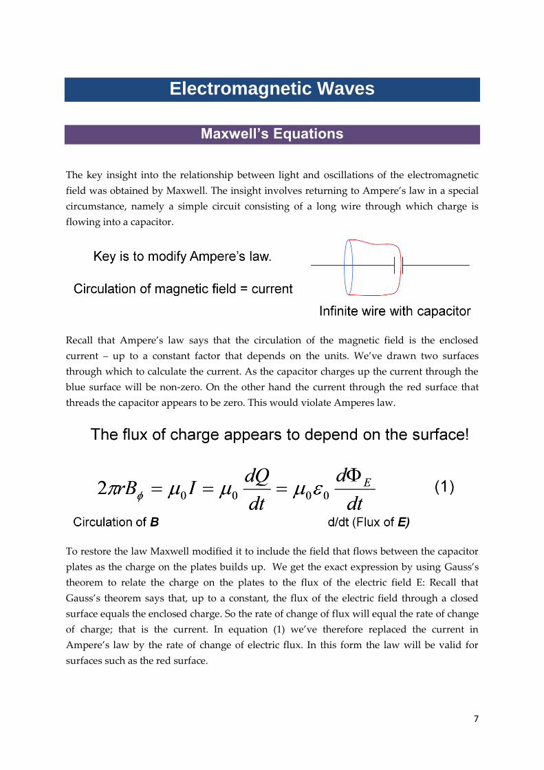
The key insight into the relationship between light and oscillations of the electromagnetic
field was obtained by Maxwell. The insight involves returning to Ampere’s law in a special
circumstance, namely a simple circuit consisting of a long wire through which charge is
flowing into a capacitor.
Recall that Ampere’s law says that the circulation of the magnetic field is the enclosed
current – up to a constant factor that depends on the units. We’ve drawn two surfaces
through which to calculate the current. As the capacitor charges up the current through the
blue surface will be non-zero. On the other hand the current through the red surface that
threads the capacitor appears to be zero. This would violate Amperes law.
To restore the law Maxwell modified it to include the field that flows between the capacitor
plates as the charge on the plates builds up. We get the exact expression by using Gauss’s
theorem to relate the charge on the plates to the flux of the electric field E: Recall that
Gauss’s theorem says that, up to a constant, the flux of the electric field through a closed
surface equals the enclosed charge. So the rate of change of flux will equal the rate of change
of charge; that is the current. In equation (1) we’ve therefore replaced the current in
Ampere’s law by the rate of change of electric flux. In this form the law will be valid for
surfaces such as the red surface.

8
In order that Ampere’s law remains valid under all circumstances we allow both the real
currents and the electric flux to contribute to the magnetic circulation. Ampere’s law
becomes: The Circulation of the magnetic field B = the Current + the Rate of change of the
Flux of the electric field E. Because the rate of change of the flux of the electric field acts as a
current in Ampere’s law, it is called the displacement current.
Derivation of Maxwell’s Equations
To get Maxwell’s equations we’ll look at a special case. In this special situation we have an
electric field with only an x-component Ex – the y and z components of E are set to be zero.
In addition we’ll assume that Ex doesn’t depend on where in the xy plane it is measured:
we’ll assume it’s always the same. In other words Ex doesn’t depend on x or y. But we do let
it depend on the z coordinate. We also let it change in time. So in this situation Ex is assumed
to be a function of z and t. We’ll see why this is a good thing to do in a moment. How should
we simplify the magnetic B field? By trial and error we find that a useful assumption is that
B has only a y component, By, and that this also depends only on z and the time, t.
We’re now ready to write down Faraday’s law for a small square in the yz plane and
Ampere’s law for a small square in the xz plane. Why do we choose these planes? Because
for Ampere’s law we want the flux of the E field so we choose a surface perpendicular to Ex
and for Faraday’s law of induction we want the flux of the B field, so we choose a surface
perpendicular to By.
We’re now in a position to derive Maxwell’s equations for this case.

9
Application to Electromagnetic Fields
Where have we got to? – We have a system of equations for the electric and magnetic fields
in a particular situation.
But what does all this mean?
Look at the equations. Equation (1) says that a time varying B field, of the right form,
generates an E field. This is just Faraday’s law of induction. Equation (2) says that the E
field regenerates the B field. Why? Because the E-field is acting as a current in Ampere’s law.
This is still not a particularly intuitive picture. So we’ll take the maths a bit further. We’re
now going to derive the most important consequence of Maxwell’s equations, from which
we’ll see that what we’ve been talking about are in fact electromagnetic waves.
We can derive the equation governing wave motion that we met in session 3 by
manipulating equations (1) and (2). We begin by differentiating (2) with respect to t and then
substitute for dB/dt from equation (1).

10
You may recognise the resulting equation (3) – apart from the use of Ex instead of y as the
dependent variable, and the use of z instead of x as the coordinate describing the spatial
dependence, this is, what we called in section 3, the wave equation.
The speed of propagation of the wave is 1/ 0 0 which is numerically very close to the speed
of light. Since there is nothing that has a speed close to that of light that isn’t in fact light, we
take it that these equations describe light in terms of time-varying electric and magnetic
fields.
Work out ( 0 0)-1/2
Starting from (1) derive the wave equation for By
Checking solutions
As a check we can show that this equation has a wave-like solution. We let the electric field
Ex have the usual form of a harmonic wave in equation (1) and compute the second
derivatives with respect to z and t as shown.
The wave equation specifies how the second derivatives are related. We can check that the
required relation in equation (3) of the previous section will be satisfied if and k are
related as in equation (2) where we’ve put c for the speed of light.

11
The wave equation for the magnetic field B will be satisfied by a similar harmonic wave. But
what is the relation between the phases of B and E? Let’s see.
Relation between E and B
To get the relation between E and B we go back to Maxwell’s equations.
We’ll guess the relation and then check it. We’ve guess that if E is proportional to cos( t-kz)
then so is B. We’ve checked the first of Maxwell’s equations below and found that the
amplitude of the magnetic oscillation is 1/c times smaller than the electric component. This is
just what we might expect from our investigation of the Biot Savart law is session 5. We’ll
leave you to check the second Maxwell equation.
Our second conclusion from this calculation is that E and B are IN PHASE. A propagating
electromagnetic wave therefore looks like the illustration in the figure, with E and B
oscillating together.

12
The Electromagnetic Spectrum
The waves we are talking about here are called plane waves because the fields are constant
on xy planes. We can think of the xy planes as forming the wavefronts progressing in the z
direction as shown here:
The parameters k and can take any values so long as /k = c, the speed of light. So the
wavelength of the waves can range from as large as you please to as small as you please.
Thus, Maxwell’s equations describe the whole electromagnetic spectrum from radio waves
to gamma rays: they are all oscillations of the electric and magnetic fields.
Polarisation
Electromagnetic waves come in more complex forms than the simple infinite plane waves
that we have described so far. We’re not going to take that any further here. But there is one
complication we’ll need – the polarisation of the wave.
So far we’ve considered an E field in the x direction and a B field in the y direction. Suppose
we swap the two to get an E field in the y direction and a B field in the x direction. This is
obviously a solution of Maxwell’s equations because we can assign the x and y labels for the
axes as we like. We describe the difference between the two waves by saying that they
exhibit different states of linear polarisation. The convention is that the direction of the E
field is used to describe the polarisation state – hence that E field (and the polarisation) can
be vertical or horizontal.

13
Recall that the E field isn’t static – this is a wave, so at any point the E field is oscillating in
amplitude with time. We can add two waves with the E fields at right angles, and with a 900
phase difference, to get a polarisation vector that rotates. In this case we say that the wave is
left or right circularly polarised.
You’ve probably some experience of polarisation – for example, sun glasses are polaroids. So
you know that the interaction of light with a material can depend on its polarisation. This
could be helpful to us in the problem of identifying wet sand, but we first need to
understand the interaction of radiation with materials. We’ll take that up in the next section.
Show how two orthogonal E vectors can be added to
produce a right circularly polarised wave.
Summary
Ampere’s law must be modified to take account of the “displacement current” that
arises from a time-varying electric field, in addition to real currents.
When this is done, it is possible for time varying electric and magnetic fields to
generate each other in a vacuum
This gives rise to electromagnetic waves which we identify as moving with the speed
of light
Therefore light waves are oscillating electric and magnetic fields
The direction of the E-vector defines the state of polarisation of the wave

14
SAQs
1. If Ex =E0sin ( t –kx), By =
a) (E0/c) sin ( t –kx)
b) (E0/c) cos ( t –kx)
c) - (E0/c) sin ( t –kx)
d) d) - (E0/c) cos ( t –kx)
2. Which of the following is the correct picture of a propagating electromagnetic wave?
The answers appear on the following page
15
Answers
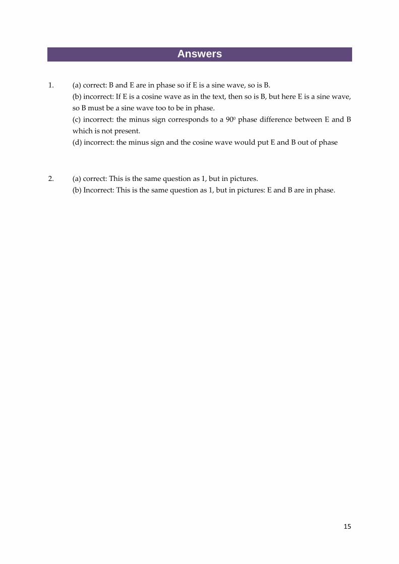
1. (a) correct: B and E are in phase so if E is a sine wave, so is B.
(b) incorrect: If E is a cosine wave as in the text, then so is B, but here E is a sine wave,
so B must be a sine wave too to be in phase.
(c) incorrect: the minus sign corresponds to a 900 phase difference between E and B
which is not present.
(d) incorrect: the minus sign and the cosine wave would put E and B out of phase
2. (a) correct: This is the same question as 1, but in pictures.
(b) Incorrect: This is the same question as 1, but in pictures: E and B are in phase.

16
Fields at Boundaries
Waves in Media
The wave picture on the left shows plane waves incident normally from a vacuum on to a
transparent medium. The frequency of the wave is unchanged as it propagates from one
medium to the other. The wavelength does change – it is smaller in the medium with higher
refractive index. On the right, we have drawn in the normals to the wavefronts. This gives
us the ray picture of geometrical optics. We can use the ray representation in situations
where there are no wavelike effects - that is, where the light is travelling in straight lines.
The speed of the light is lower in a medium than in a vacuum. This commonly raises a
number of issues.
First does the light change colour from one medium to the next? If not, why not? We’ll leave
you to discuss this.
Second, in the wave picture the light slows down instantaneously on entering the medium –
in the photon picture do photons undergo infinite deceleration at the boundary? In fact, they
do not. The photons entering the medium interact with it and lose their identity. The

17
particles propagating in the medium are different photons – we’ll see this in more detail on
the next section.
Dielectric constant and refractive index n
What causes the slowing down of light in a dense medium? We can represent the medium
as a collection of atomic dipoles which oscillate in the presence of an electric or magnetic
field. This oscillation contributes to the electromagnetic field in the medium, altering it from
the incident field. Consider an oscillating electric dipole. The movement of charge
constitutes a current in the medium. This current is only present because of the original
oscillating electric field. So, for small fields at least, we can assume that the current depends
linearly on the field. We can also assume that it depends on the time derivative of the field,
because the dipoles won’t oscillate if the field is not varying. Thus, in a medium, we must
modify Maxwell’s equations by the extra term in equation (2) here. In this equation is a
constant relating the induced currents to the field. If you work through the maths you’ll see
that a wavelike solution for Ex now requires that equation (3) is fulfilled. The constant
quantity is the dielectric constant which we met previously in session 4.
The refractive index of a medium, n is defined by n = ck/ . It is equal to the square root of
the dielectric constant. The refractive index is also the speed of light in a vacuum, c, divided
by the speed of light in the medium, /k. Equivalently, the speed of light in the medium,
/k, equals c/n. Since refractive indices are greater than unity, this explains why light moves
more slowly in a medium.
18
Why would you expect the refractive index to depend
on frequency? (Hint: think back to session 3)
Think about why you might expect the refractive index of a medium to be a function of the
frequency of the incident light. ….
The reason can be found in the work of session 3: the way an oscillator responds to an
oscillating external force depends on the frequency of the oscillation. So the currents
induced in the dielectric by the incident field will depend on its frequency. This means that
and hence n must be frequency dependent.
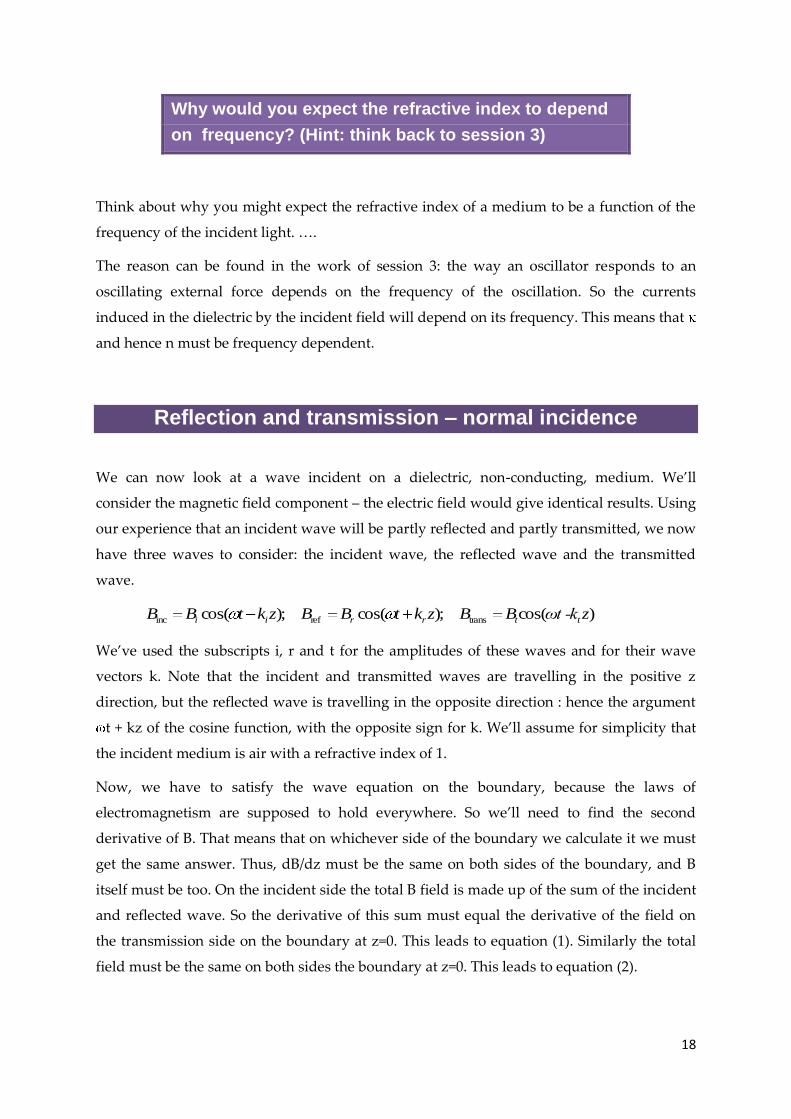
Reflection and transmission – normal incidence
We can now look at a wave incident on a dielectric, non-conducting, medium. We’ll
consider the magnetic field component – the electric field would give identical results. Using
our experience that an incident wave will be partly reflected and partly transmitted, we now
have three waves to consider: the incident wave, the reflected wave and the transmitted
wave.
)cos( );cos( );cos( transrefinc zωt -kBBzktBBzktBB ttrrii
We’ve used the subscripts i, r and t for the amplitudes of these waves and for their wave
vectors k. Note that the incident and transmitted waves are travelling in the positive z
direction, but the reflected wave is travelling in the opposite direction : hence the argument
t + kz of the cosine function, with the opposite sign for k. We’ll assume for simplicity that
the incident medium is air with a refractive index of 1.
Now, we have to satisfy the wave equation on the boundary, because the laws of
electromagnetism are supposed to hold everywhere. So we’ll need to find the second
derivative of B. That means that on whichever side of the boundary we calculate it we must
get the same answer. Thus, dB/dz must be the same on both sides of the boundary, and B
itself must be too. On the incident side the total B field is made up of the sum of the incident
and reflected wave. So the derivative of this sum must equal the derivative of the field on
the transmission side on the boundary at z=0. This leads to equation (1). Similarly the total
field must be the same on both sides the boundary at z=0. This leads to equation (2).

19
Equations (1) and (2) can be solved for the reflected field and the transmitted field in terms
of the incident field. The ratio of the field transmitted to that reflected depends on the
refractive index.
However, we don’t normally measure radiation fields directly – we usually measure the
energy flow. So how do we convert fields to energy fluxes?
20
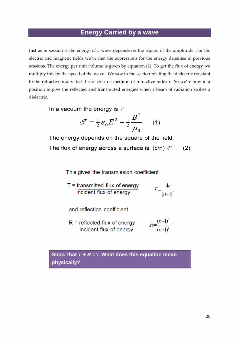
Energy Carried by a wave
Just as in session 3, the energy of a wave depends on the square of the amplitude. For the
electric and magnetic fields we’ve met the expressions for the energy densities in previous
sessions. The energy per unit volume is given by equation (1). To get the flux of energy we
multiply this by the speed of the wave. We saw in the section relating the dielectric constant
to the refractive index that this is c/n in a medium of refractive index n. So we’re now in a
position to give the reflected and transmitted energies when a beam of radiation strikes a
dielectric.
Show that T + R =1. What does this equation mean
physically?

21
How far do waves penetrate a conductor?
So far we have considered waves incident on perfectly insulating media, that is we have
neglected the effects of conductivity. In a real medium any incident radiation will not only
shake the atomic dipoles but will also move free charges around. The motion of free charge
also constitutes a current that will add to the field. We know that a static field inside a
conductor is zero, because the charges move to neutralise any field. If the charges respond to
a time varying field entirely without resistance then they will instantaneously neutralise a
time varying field inside the conductor as well. However, if the conductivity is finite,
conduction currents will flow under the influence of the electric vector of the wave. This
current will dissipate energy through ohmic heating, so the wave will lose energy as it
propagates. The distance over which the amplitude of the E vector falls to 1/e of its initial
value is called the skin depth. The skin depth is given by equation (1).
Why is this relevant to our problem of detecting leaking pipes? – From this point of view,
water is a conductor. Thus if em radiation penetrates wet sand it may be reflected not from
the sand surface, but from buried objects – such as the water pipe itself!
At low frequencies, for example for radio waves, the skin depth of a wave of frequency in
a medium of conductivity is given by equation (1). In a good conductor the skin depth is
quite small. In copper for example the skin depth is about 1/100 th of a mm.
Example: a copper conductor
= 5.76 x 10⁷ ohm-1 metre-1
0 = 8.85 x 10⁻¹² farad metre-1
c = 3 x 10⁸ m s-1
= 2 x 10¹⁰ rad s-1 (microwaves)
Then: = 7 x 10⁻⁶ m

22
Summary
Waves in a medium with refractive index n travel at speed c/n
The refractive index is the square root of the dielectric constant and depends on
frequency
The energy in the electromagnetic field is: 0
2
212
021
BE
The ratio of transmitted energy to reflected energy depends on n
The energy travels at speed c/n in a medium
Waves penetrate into a conductor a distance given by the skin depth: 2
02 c

23
SAQs
1. Why is it difficult to send high frequency electromagnetic waves down copper wires?
a) The electrons move too slowly
b) The resonance width is too low
c) High dissipation leads to confinement of the field
d) The signal is totally internally reflected
2. Why is the skin depth for water different from a copper conductor?
a) Water is a poor conductor
b) Water is transparent
c) Because the dielectric constant of water is larger
3. Communication with submarines from a base station on land (using the
electromagnetic spectrum) requires
a) High frequency radiation
b) Low frequency radiation
c) High power at any frequency
4. For normal incidence the polarisation of the reflected wave is:
a) the same as that of the incident wave
b) 900 to the incident wave
c) random (i.e always unpolarised)
The answers appear on the following page

24
Answers
1. a)Incorrect: the signal is not carried by translational motion of electrons, but by
oscillations communicated at speed c/n
b) Incorrect: the conduction electrons in a metal are free so the resonance frequency
and width are irrelevant
c) correct: the conductivity of copper is high, so the electric vector gives rise to large
currents and hence large I2R losses. Fields do not therefore penetrate very far so the
skin depth in a metal is very small. Thus electromagnetic waves are confined to the
surface layer.
d) incorrect: it would be relevant if one were to try to shine a beam down the copper
wire, because copper like all metals is a good reflector as a consequence of the small
skin depth. However, the signal would be generated electromagnetically in the wire.
2. a) correct: the formula for skin depth involves the conductivity in the denominator so
high conductivity implies small skin depth. This is also physically reasonable
because the high conductivity implies large currents, hence large I2R losses and small
penetration.
b) incorrect: water is transparent to optical wavelengths because the skin depth at
these wavelengths is large, not the other way round.
c) the statement is true but not relevant because the dielectric constant doesn’t affect
the skin depth.
3. a) incorrect: this is another skin depth problem since the em waves have to penetrate
the ocean.
b) correct: only the lowest frequencies can penetrate to depth in sea water (which has
a relatively high conductivity compared to tap water, say. Pure water is non-
conducting.)
c) incorrect: the signal fall off exponentially with distance so while high power might
have some effect it’s not sufficient on its own
4. a) correct: the E and B fields each have to be continuous across the boundary which
means that they each have to align independently
b) and c) incorrect: a wave may be polarised on reflection by selective polarisation-
dependent reflectivity but the polarisation of an individual wave doesn’t change on
reflection.

25
Reflection and Refraction
Oblique Incidence
The first observation we usually encounter in discussing reflection is the equality of the
angles of incidence and reflection. Why are these equal?
We can think of the wave vector k which gives the direction and wavenumber (or
wavelength) of the wave as having components parallel to the surface and perpendicular to
it. Let’s take the example of a perfect conductor. The reflected and transmitted waves have
to cancel along the surface, so k// must be the same for the incident and reflected waves. But
the wave numbers of the reflected and incident waves are also the same in the same
medium. So k must be the same for both. This means the angles are the same.
26
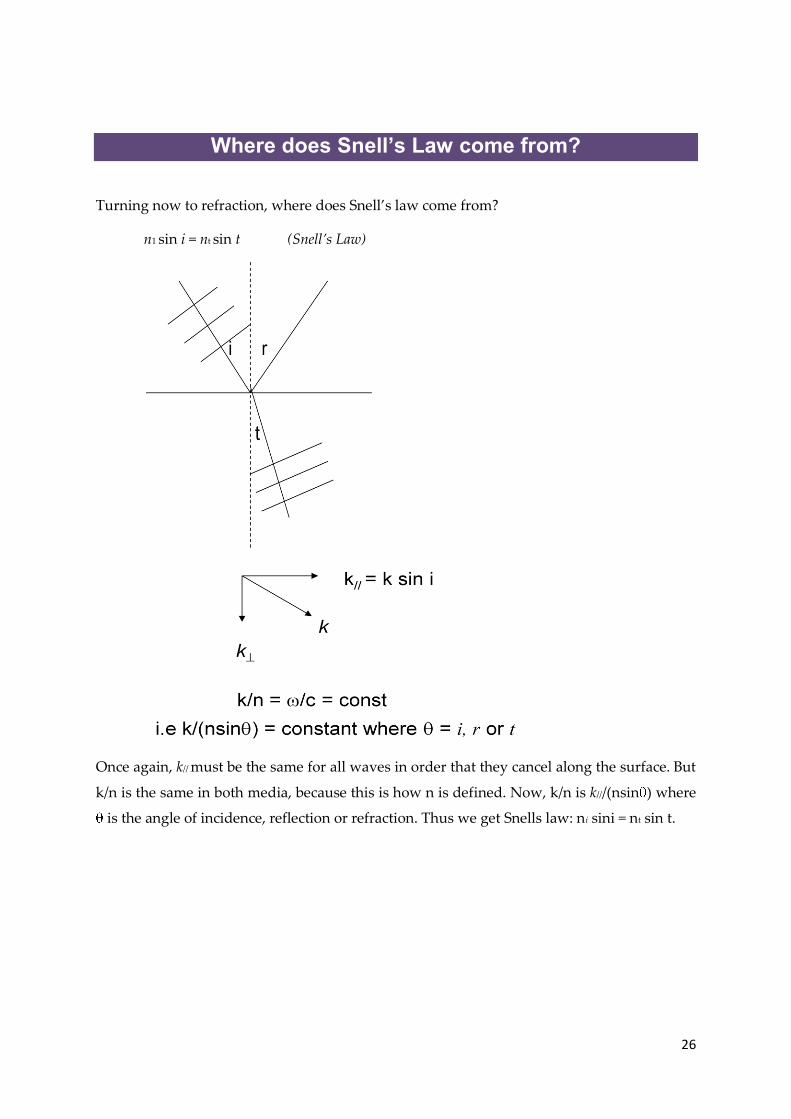
Where does Snell’s Law come from?
Turning now to refraction, where does Snell’s law come from?
n1 sin i = nt sin t (Snell’s Law)
Once again, k// must be the same for all waves in order that they cancel along the surface. But
k/n is the same in both media, because this is how n is defined. Now, k/n is k///(nsin ) where
is the angle of incidence, reflection or refraction. Thus we get Snells law: ni sini = nt sin t.

27
The Brewster Angle
An interesting effect occurs for an incident beam polarised such that the electric field is in
the plane of incidence – that is the plane containing the incident ray and the normal to the
surface, or the plane of the page as it is usually drawn. The effect is this: at a particular angle
of incidence there is no reflected ray.
Brewster angle: I = tan-1(nt / ni)
This can be understood by recalling that reflection occurs because the dipoles in the medium
are made to oscillate by the incoming field. The oscillating dipoles produce their own
radiation field which contributes the whole of the reflected field and part of the transmitted
field. But a dipole does not radiate along its axis. Thus if the transmitted ray is at 900 to
where the reflected ray would have been, there will be no reflected ray. This occurs at an
angle of incidence called the Brewster angle which depends on the refractive indices of the
two media.

28
Poynting vector
Finally we come to another way of looking at the flux of energy which gives us both the
direction and magnitude of the energy flow in a field. This is called the Poynting vector. This
section shows how it is derived for a plane wave. We start from the usual expression for the
energy per unit volume of an electromagnetic field in equation (1). We take the time
derivative of the energy in equation (2). We then use Maxwell’s equations for a plane wave
to eliminate the time derivatives to get equation (3) which is rewritten as (4). This gives us
the difference in energy entering and leaving a planar region along the z-axis in terms of the
rate of change of energy in the region.
α
Reflected
Intensity
100%
0%
Angle 00 900
Brewster Angle

29
In equation (5) we have given a general expression for the Poynting vector, S, that applies to
any situation, not just plane waves.
Summary
For oblique incidence:
The angle of reflection equals the angle of incidence
The angle of refraction t obeys Snell’s law: tnin ti sinsin
For the electric vector polarised in the plane of incidence there is no reflected ray at
the Brewster angle tan-1 (ni/nt)
The Poynting vector E x B/ 0 gives the energy flux in a wave.

30
SAQs
1. Unpolarised light is reflected obliquely from a plane surface. What is the state of
polarisation of the reflected beam?
a) unpolarised
b) E vector parallel to the plane
c) partly polarized
2. In passing from glass to air a light ray bends
a) away from the normal
b) towards the normal
c) Neither: it is totally reflected
The answers appear on the following page

31
Answers
1. a) incorrect: the different components of polarisation are reflected more or less
strongly so there will be a net polarisation in the reflected beam even if the incident
beam is unpolarised.
b) incorrect: this would be true at the Brewster angle and is a way of producing
linearly polarised light.
c) correct: the different components of polarisation are reflected more or less strongly
so there will be a net polarisation in the reflected beam even if the incident beam is
unpolarised.
2. a) correct: the easiest way to see this is to trace a ray backwards. The paths are time-
reversible because there is no dissipation in geometrical optics (i.e for non-
conducting dielectrics or perfectly conducting mirrors).
b) incorrect: the wave is travelling faster in air than in glass, so the bending is away
from the normal.
c) incorrect: at a large enough angle of incidence this will be true, but it is not the case
for small angles of incidence.

32
Water Pipes in the Desert
What method might we use to determine the difference in refractive index between wet and
dry sand? :
Reflection coefficient
Brewster angle
Look up the dielectric constant of water and predict
the difference in Brewster angle between wet and dry
sand. Why might microwaves be better than optical?
Sand has a refractive index of around 2 to 3. If you look up the dielectric constant of water
you’ll find a range of values because it is highly dependent on the frequency of radiation.
Typical values for the dielectric constant in the microwave region are around 80, whereas
the refractive index in the optical we know to be around 1.3, which is far from the square
root of 80. This suggests that we might get a larger difference between wet and dry sand if
we use microwaves in our detection system.
Results for Sand
So here we have some results for the reflection of polarised microwaves from sand. The first
thing you will notice is that the curve does not look much like the theoretical curve where
we discussed the Brewster angle. Before we attempt to use the method therefore we should
try to understand where the discrepancies arise. They are not just experimental error
(although the experiment is quite difficult to do accurately).

33
Theoretical Curve:
)(tan
)(tan
)(sin
)(sin
2
2
||
2
2
r
r
We suggest that you come up with your own ideas on this.
02468
10121416
30 50 70
Am
pli
tud
e (
mV
)
Angle of incicence (deg)
IR Dry sand 250-500 micro metres
0
2
4
6
8
10
0 20 40 60 80 100
Am
pli
tud
e (
mV
)
Angle of incidence (deg)
IR wet 250-500 micro meters
Reflected
Intensity
100%
0%
Angle 00 900
Brewster Angle

34
Additional Problems
Problem 1: Solar sails
A solar sail is a means of powering a spacecraft that works by capturing the momentum of
radiation from the Sun.
Momentum and energy: the flux of momentum P carried by a beam of light is related to its
energy flux E by P=E/c.
Image2
Estimate the acceleration of a solar sail at the Earth and comment on your result. (Your
answer will depend on the size you assume for your sail.)
Flux of momentum from Sun = L/(4 r2 c);
Force = rate of change of momentum= 2x Area x L/(4 r2 c)
Acceleration = Force /Mass
2 Solar Sail in Orbiter, FlyingSinger, as posted on www.flickr.com. Creative Commons Licenced

35
Answer: We make the acceleration about 5x10⁻⁸ m s-2 for a sail with area 1000m 2 and a
spacecraft of mass 100 tonnes. Don’t forget the factor 2 for the momentum change on
reflection. You might like to think about where the energy comes from that ends up as
kinetic energy of the spacecraft. Any practical accelerations are likely to be small, but the
method is interesting because it can be used to accelerate a spacecraft over long periods
thereby building up significant speeds.
36
Overall Summary
Maxwell’s equations arise from a modification of Ampere’s law to include the
displacement current
Maxwell’s equations predict the existence of electromagnetic waves travelling with
the speed of light
The waves are transverse with the electric and magnetic fields orthogonal and
perpendicular to the direction of motion
The speed of an electromagnetic wave in a medium of refractive index n is c/n.
Maxwell’s equations can be used to derive the laws of reflection and of refraction
At the Brewster angle a wave polarised parallel to the plane of incidence is not
reflected
The Poynting vector gives the energy flux in a wave
37
Meta tags
Author: Emma Bunce.
Owner: University of Leicester
Title: Enhancing Physics Knowledge for Teaching – Maxwell’s Equations
Keywords: Magnetism; Electricity; Magnetism; Fields; sfsoer; ukoer
Description: In this session we’re going to look at how electricity and magnetism can be
unified into a system of equations, named after James Clerk Maxwell, the Scottish physicist
who first proposed them. Then we’ll see how this leads to an understanding of the nature of
electromagnetic radiation.
Creative Commons Licence: BY-NC-SA
http://creativecommons.org/licenses/by-nc-sa/2.0/uk/
Language: English
Version: 1.0
Additional Information
This pack is the Version 1.0 release of the module. Additional information can be obtained
by contacting the Centre for Interdisciplinary Science at the University of Leicester.
http://www.le.ac.uk/iscience