Session 4: Plasma facing components - Nucleus Documents... · 15/11/2017 1 Session 4: Plasma facing...
52
1 15/11/2017 Session 4: Plasma facing components 2nd IAEA Technical Meeting on Divertor Concepts 2nd IAEA Technical Meeting on Divertor Concepts Eliseo Visca, ENEA
Transcript of Session 4: Plasma facing components - Nucleus Documents... · 15/11/2017 1 Session 4: Plasma facing...
1 15/11/2017
Session 4: Plasma facing components
2nd IAEA Technical Meeting on Divertor Concepts
2nd IAEA Technical Meeting on Divertor Concepts
Eliseo Visca, ENEA
2
Introduction
Outstanding Technical Challenges with Gaps beyond ITER
15/11/2017
Blanket and fuel cycle
FW and PFCs ‘Fusion’ auxiliares
Structural materials
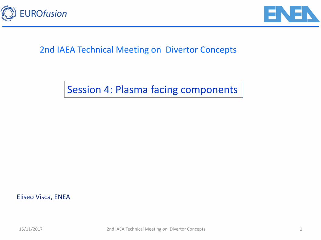
From ITER to DEMO to Fusion Power Plant (FPP)
the DEMO goals are to demonstrate…
• a workable solution for all physics and technology questions
• large scale net electricity production
• T self-sufficient fuel cycle
• high reliability and availability over a reasonable time span
2nd IAEA Technical Meeting on Divertor Concepts
3
Introduction
15/11/2017
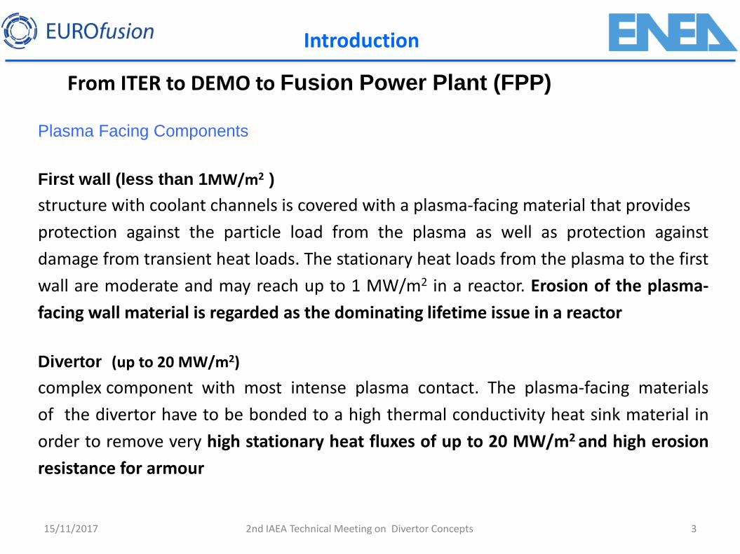
Plasma Facing Components
First wall (less than 1MW/m2 )
structure with coolant channels is covered with a plasma-facing material that provides
protection against the particle load from the plasma as well as protection against
damage from transient heat loads. The stationary heat loads from the plasma to the first
wall are moderate and may reach up to 1 MW/m2 in a reactor. Erosion of the plasma-
facing wall material is regarded as the dominating lifetime issue in a reactor
Divertor (up to 20 MW/m2)
complex component with most intense plasma contact. The plasma-facing materials
of the divertor have to be bonded to a high thermal conductivity heat sink material in
order to remove very high stationary heat fluxes of up to 20 MW/m2 and high erosion
resistance for armour
2nd IAEA Technical Meeting on Divertor Concepts
From ITER to DEMO to Fusion Power Plant (FPP)
4
Introduction
15/11/2017
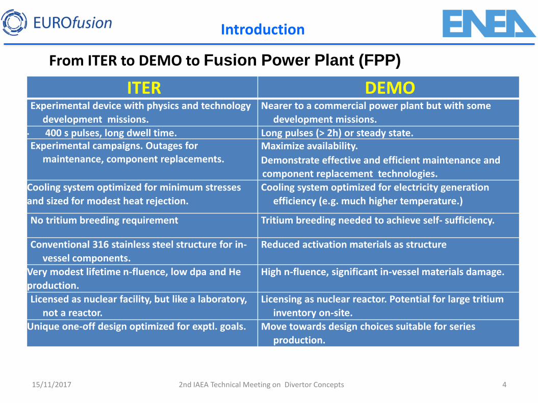
ITER DEMO Experimental device with physics and technology
development missions.
Nearer to a commercial power plant but with some
development missions.
• 400 s pulses, long dwell time. Long pulses (> 2h) or steady state. Experimental campaigns. Outages for
maintenance, component replacements. Maximize availability.
Demonstrate effective and efficient maintenance and component replacement technologies.
Cooling system optimized for minimum stresses
and sized for modest heat rejection.
Cooling system optimized for electricity generation
efficiency (e.g. much higher temperature.)
No tritium breeding requirement Tritium breeding needed to achieve self- sufficiency.
Conventional 316 stainless steel structure for in-
vessel components.
Reduced activation materials as structure
Very modest lifetime n-fluence, low dpa and He
production.
High n-fluence, significant in-vessel materials damage.
Licensed as nuclear facility, but like a laboratory,
not a reactor.
Licensing as nuclear reactor. Potential for large tritium
inventory on-site.
Unique one-off design optimized for exptl. goals. Move towards design choices suitable for series
production.
2nd IAEA Technical Meeting on Divertor Concepts
From ITER to DEMO to Fusion Power Plant (FPP)
5
Introduction
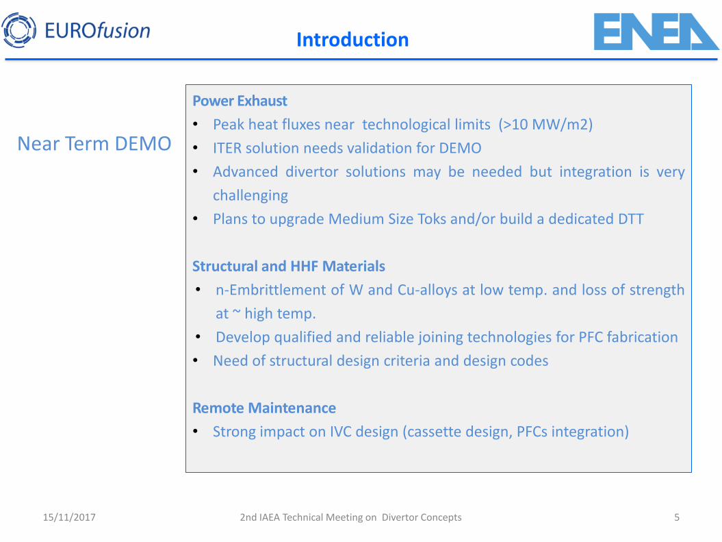
Near Term DEMO
15/11/2017
Power Exhaust
• Peak heat fluxes near technological limits (>10 MW/m2)
• ITER solution needs validation for DEMO
• Advanced divertor solutions may be needed but integration is very
challenging
• Plans to upgrade Medium Size Toks and/or build a dedicated DTT
Structural and HHF Materials
• n-Embrittlement of W and Cu-alloys at low temp. and loss of strength
at ~ high temp.
• Develop qualified and reliable joining technologies for PFC fabrication
• Need of structural design criteria and design codes
Remote Maintenance
• Strong impact on IVC design (cassette design, PFCs integration)
2nd IAEA Technical Meeting on Divertor Concepts
Conceptual Design Approach
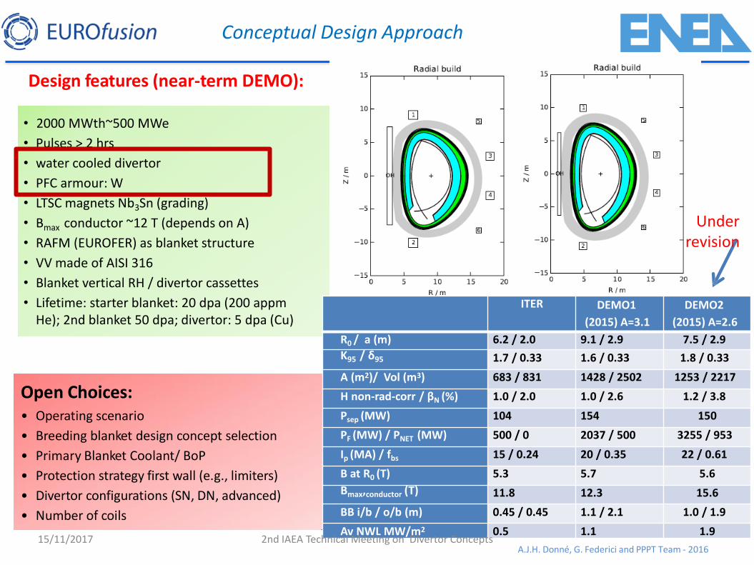
Design features (near-term DEMO):
• 2000 MWth~500 MWe
• Pulses > 2 hrs
• water cooled divertor
• PFC armour: W
• LTSC magnets Nb3Sn (grading)
• Bmax conductor ~12 T (depends on A)
• RAFM (EUROFER) as blanket structure
• VV made of AISI 316
• Blanket vertical RH / divertor cassettes
• Lifetime: starter blanket: 20 dpa (200 appm He); 2nd blanket 50 dpa; divertor: 5 dpa (Cu)
Open Choices: • Operating scenario
• Breeding blanket design concept selection
• Primary Blanket Coolant/ BoP
• Protection strategy first wall (e.g., limiters)
• Divertor configurations (SN, DN, advanced)
• Number of coils
DEMO2
A.J.H. Donné, G. Federici and PPPT Team | IEA-FPCC | Paris | 27-28/01/2016| Page 10
DEMO1
Under revision
ITER DEMO1
(2015) A=3.1
DEMO2
(2015) A=2.6
R0 / a (m) 6.2 / 2.0 9.1 / 2.9 7.5 / 2.9
Κ95 / δ95 1.7 / 0.33 1.6 / 0.33 1.8 / 0.33
A (m2)/ Vol (m3) 683 / 831 1428 / 2502 1253 / 2217
H non-rad-corr / βN (%) 1.0 / 2.0 1.0 / 2.6 1.2 / 3.8
Psep (MW) 104 154 150
PF (MW) / PNET (MW) 500 / 0 2037 / 500 3255 / 953
Ip (MA) / fbs 15 / 0.24 20 / 0.35 22 / 0.61
B at R0 (T) 5.3 5.7 5.6
Bmax,conductor (T) 11.8 12.3 15.6
BB i/b / o/b (m) 0.45 / 0.45 1.1 / 2.1 1.0 / 1.9
Av NWL MW/m2 0.5 1.1 1.9
A.J.H. Donné, G. Federici and PPPT Team - 2016 15/11/2017 2nd IAEA Technical Meeting on Divertor Concepts
15/11/2017 7
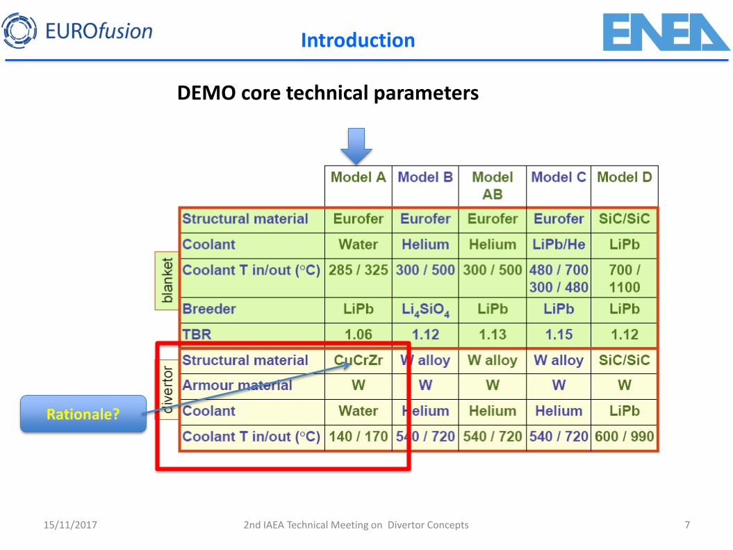
DEMO core technical parameters
Rationale?
2nd IAEA Technical Meeting on Divertor Concepts
Introduction
8
Introduction
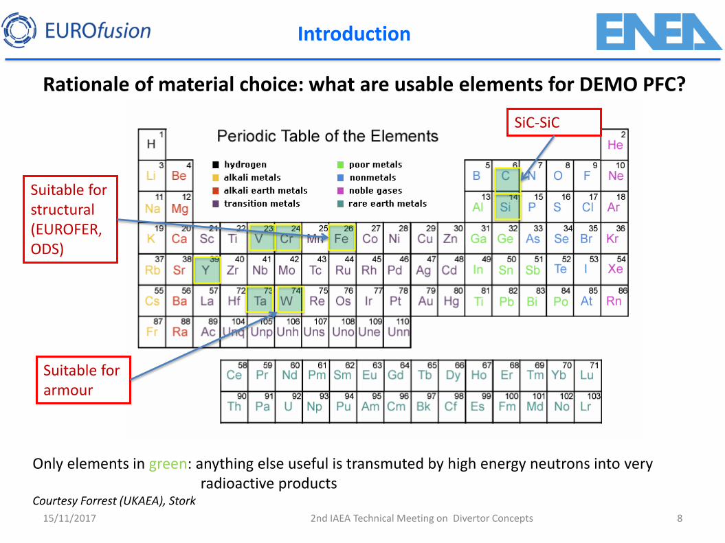
Rationale of material choice: what are usable elements for DEMO PFC?
15/11/2017
Only elements in green: anything else useful is transmuted by high energy neutrons into very radioactive products
Courtesy Forrest (UKAEA), Stork
Suitable for armour
Suitable for structural (EUROFER, ODS)
SiC-SiC
2nd IAEA Technical Meeting on Divertor Concepts
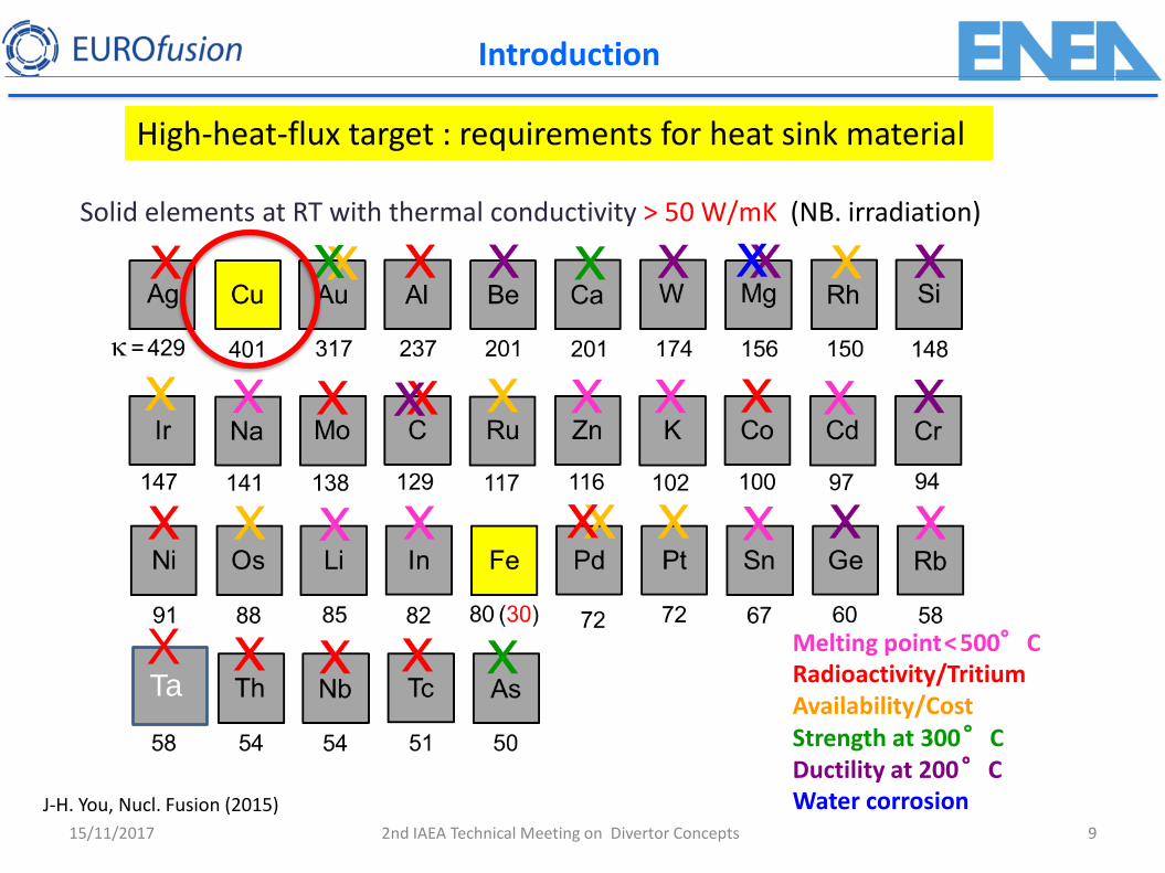
Melting point < 500°C Radioactivity/Tritium Availability/Cost Strength at 300 °C Ductility at 200 °C Water corrosion
Solid elements at RT with thermal conductivity > 50 W/mK (NB. irradiation)
Ta X
High-heat-flux target : requirements for heat sink material
J-H. You, Nucl. Fusion (2015)
15/11/2017 2nd IAEA Technical Meeting on Divertor Concepts 9
Introduction
15/11/2017 10
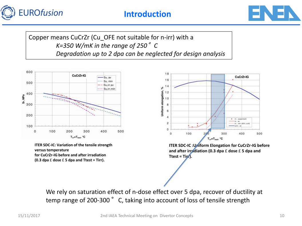
Copper means CuCrZr (Cu_OFE not suitable for n-irr) with a K=350 W/mK in the range of 250°C Degradation up to 2 dpa can be neglected for design analysis
ITER SDC-IC: Variation of the tensile strength versus temperature for CuCrZr-IG before and after irradiation (0.3 dpa £ dose £ 5 dpa and Ttest = Tirr).
ITER SDC-IC :Uniform Elongation for CuCrZr-IG before and after irradiation (0.3 dpa £ dose £ 5 dpa and Ttest = Tirr).
We rely on saturation effect of n-dose effect over 5 dpa, recover of ductility at temp range of 200-300 °C, taking into account of loss of tensile strength
2nd IAEA Technical Meeting on Divertor Concepts
Introduction
15/11/2017 11
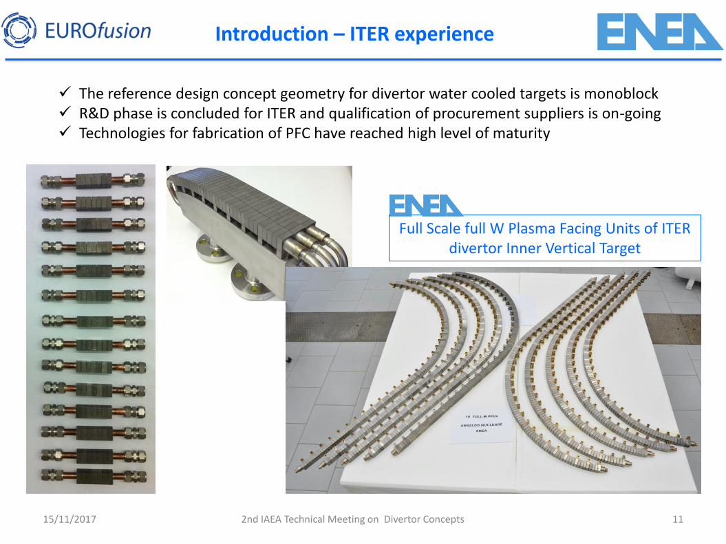
The reference design concept geometry for divertor water cooled targets is monoblock R&D phase is concluded for ITER and qualification of procurement suppliers is on-going Technologies for fabrication of PFC have reached high level of maturity
2nd IAEA Technical Meeting on Divertor Concepts
Introduction – ITER experience
Full Scale full W Plasma Facing Units of ITER divertor Inner Vertical Target
15/11/2017 12
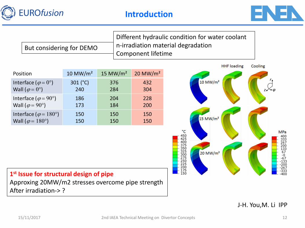
But considering for DEMO
Different hydraulic condition for water coolant n-irradiation material degradation Component lifetime
1st Issue for structural design of pipe Approxing 20MW/m2 stresses overcome pipe strength After irradiation-> ?
2nd IAEA Technical Meeting on Divertor Concepts
Introduction
J-H. You,M. Li IPP
15/11/2017 13
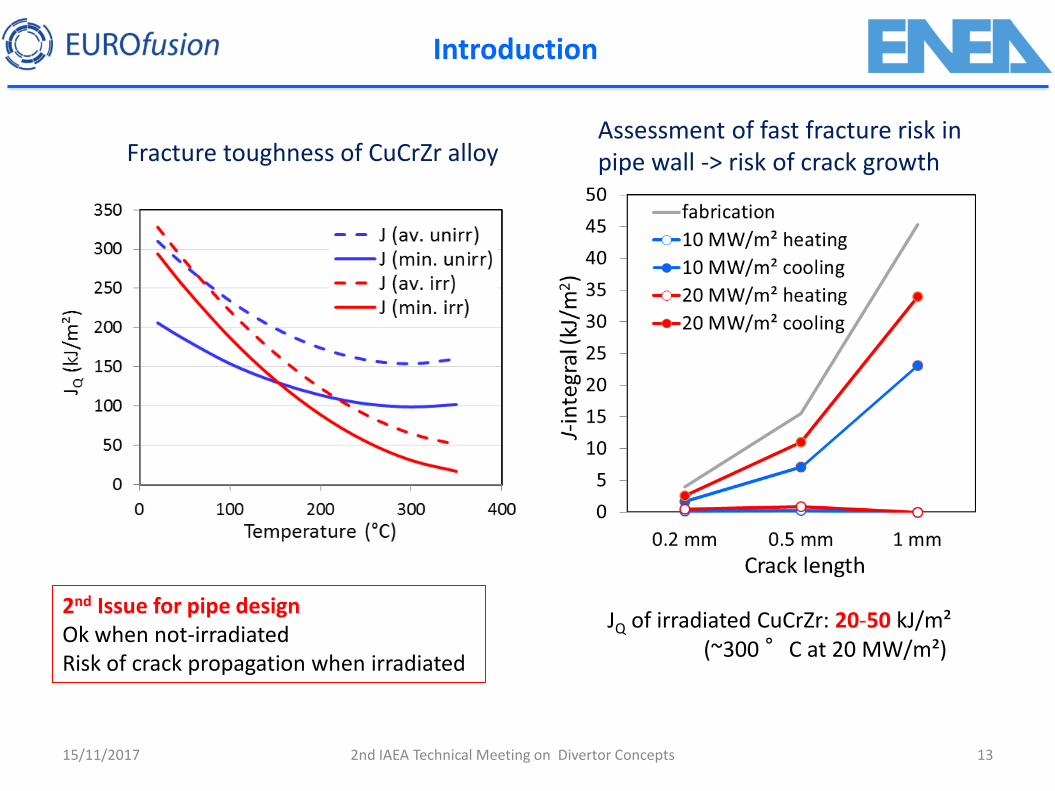
Assessment of fast fracture risk in pipe wall -> risk of crack growth
JQ of irradiated CuCrZr: 20-50 kJ/m² (~300 °C at 20 MW/m²)
Fracture toughness of CuCrZr alloy
2nd Issue for pipe design Ok when not-irradiated Risk of crack propagation when irradiated
2nd IAEA Technical Meeting on Divertor Concepts
Introduction
15/11/2017 14
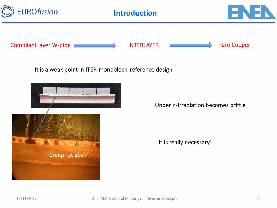
Compliant layer W-pipe Pure Copper
It is a weak point in ITER-monoblock reference design
Creep-fatigue?
Under n-irradiation becomes brittle
It is really necessary?
INTERLAYER
2nd IAEA Technical Meeting on Divertor Concepts
Introduction
15/11/2017 15
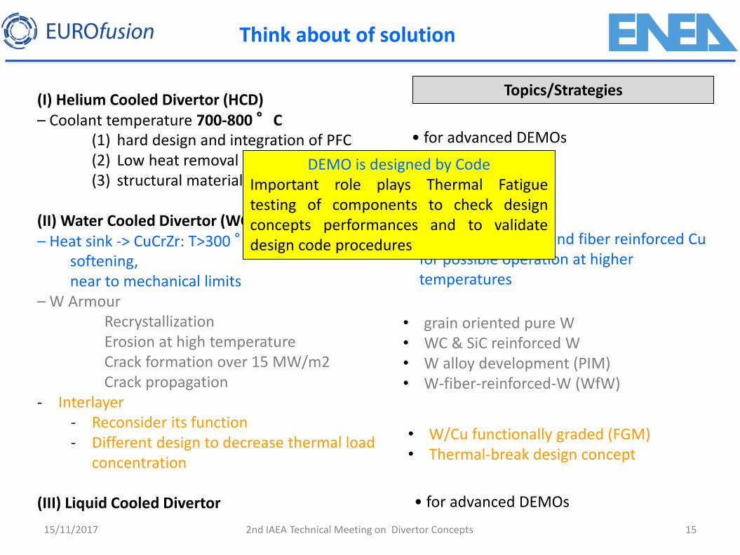
(I) Helium Cooled Divertor (HCD) – Coolant temperature 700-800 °C
(1) hard design and integration of PFC (2) Low heat removal capability (3) structural material TBD
(II) Water Cooled Divertor (WCD) – Heat sink -> CuCrZr: T>300 °C softening, near to mechanical limits – W Armour
Recrystallization Erosion at high temperature Crack formation over 15 MW/m2 Crack propagation
- Interlayer - Reconsider its function - Different design to decrease thermal load
concentration
(III) Liquid Cooled Divertor
• laminates, particle and fiber reinforced Cu for possible operation at higher temperatures
• for advanced DEMOs
Think about of solution
• grain oriented pure W • WC & SiC reinforced W • W alloy development (PIM) • W-fiber-reinforced-W (WfW)
Topics/Strategies
• W/Cu functionally graded (FGM) • Thermal-break design concept
DEMO is designed by Code Important role plays Thermal Fatigue testing of components to check design concepts performances and to validate design code procedures
2nd IAEA Technical Meeting on Divertor Concepts
• for advanced DEMOs
15/11/2017 16
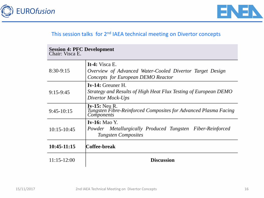
This session talks for 2nd IAEA technical meeting on Divertor concepts
Session 4: PFC Development Chair: Visca E.
8:30-9:15 It-4: Visca E. Overview of Advanced Water-Cooled Divertor Target Design
Concepts for European DEMO Reactor
9:15-9:45
Iv-14: Greuner H. Strategy and Results of High Heat Flux Testing of European DEMO
Divertor Mock-Ups
9:45-10:15 Iv-15: Neu R. Tungsten Fibre-Reinforced Composites for Advanced Plasma Facing Components
10:15-10:45
Iv-16: Mao Y. Powder Metallurgically Produced Tungsten Fiber-Reinforced
Tungsten Composites
10:45-11:15 Coffee-break
11:15-12:00 Discussion
2nd IAEA Technical Meeting on Divertor Concepts
Presenting: Visca Eliseo, ENEA Thanks to All Task Owners (CCFE, CEA, KIT, IPP, MPG, ENEA)
Overview of advanced water-cooled divertor target design concepts for European DEMO
reactor
15/11/2017 17 2nd IAEA Technical Meeting on Divertor Concepts
Eliseo Viscaa, J.H. Youc, F. Crescenzia, H. Greunerc, T. Barrettd, M. Richoub, A.v. Müllerc a Department of Fusion and Technology for Nuclear Safety and Security – ENEA, Italy b CEA, IRFM, F-13108 Saint-Paul-Lez-Durance, France c Max Planck Institute for Plasma Physics, Boltzmann Str. 2, 85748 Garching, Germany d CCFE, Culham Science Centre, Abingdon OX14 3DB, United Kingdom
18
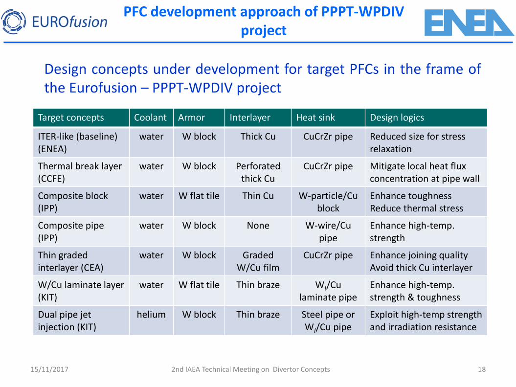
PFC development approach of PPPT-WPDIV project
15/11/2017
Design concepts under development for target PFCs in the frame of the Eurofusion – PPPT-WPDIV project
Target concepts Coolant Armor Interlayer Heat sink Design logics
ITER-like (baseline) (ENEA)
water W block Thick Cu CuCrZr pipe Reduced size for stress relaxation
Thermal break layer (CCFE)
water W block Perforated thick Cu
CuCrZr pipe Mitigate local heat flux concentration at pipe wall
Composite block (IPP)
water W flat tile Thin Cu W-particle/Cu block
Enhance toughness Reduce thermal stress
Composite pipe (IPP)
water W block None W-wire/Cu pipe
Enhance high-temp. strength
Thin graded interlayer (CEA)
water W block Graded W/Cu film
CuCrZr pipe Enhance joining quality Avoid thick Cu interlayer
W/Cu laminate layer (KIT)
water W flat tile Thin braze Wl/Cu laminate pipe
Enhance high-temp. strength & toughness
Dual pipe jet injection (KIT)
helium W block Thin braze Steel pipe or Wl/Cu pipe
Exploit high-temp strength and irradiation resistance
2nd IAEA Technical Meeting on Divertor Concepts

19
PFC development approach of PPPT-WPDIV project
Helium-cooled Target Development (EUROFER ?) W Laminate Tube concept: W composite laminate tube with W
armour and helium jet cartridge (KIT) Dual pipe jet injection impingement concept + W-PIM (KIT)
15/11/2017
S. Antusch, J. Reisen, . Norajitra al
2nd IAEA Technical Meeting on Divertor Concepts
35
0°
C
550°C
1000 mm
Eurofer
350°C –
550°C
Eurofer
heat load
20
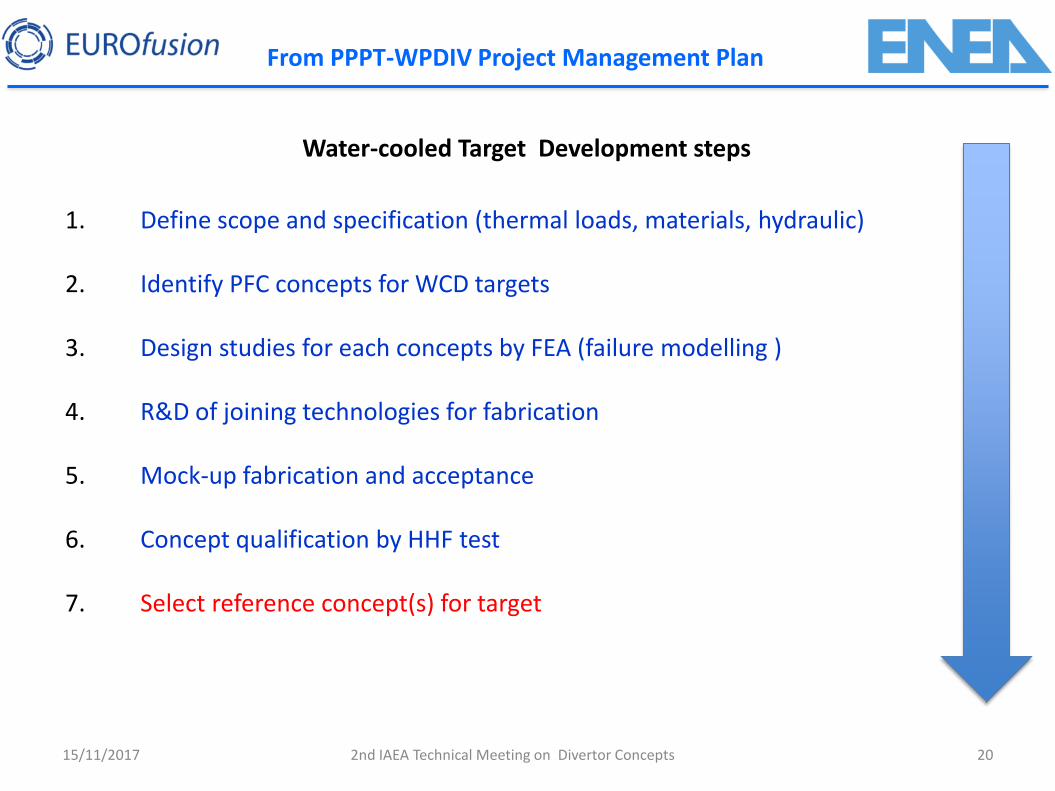
From PPPT-WPDIV Project Management Plan
Water-cooled Target Development steps
1. Define scope and specification (thermal loads, materials, hydraulic)
2. Identify PFC concepts for WCD targets
3. Design studies for each concepts by FEA (failure modelling )
4. R&D of joining technologies for fabrication
5. Mock-up fabrication and acceptance
6. Concept qualification by HHF test
7. Select reference concept(s) for target
15/11/2017 2nd IAEA Technical Meeting on Divertor Concepts
21
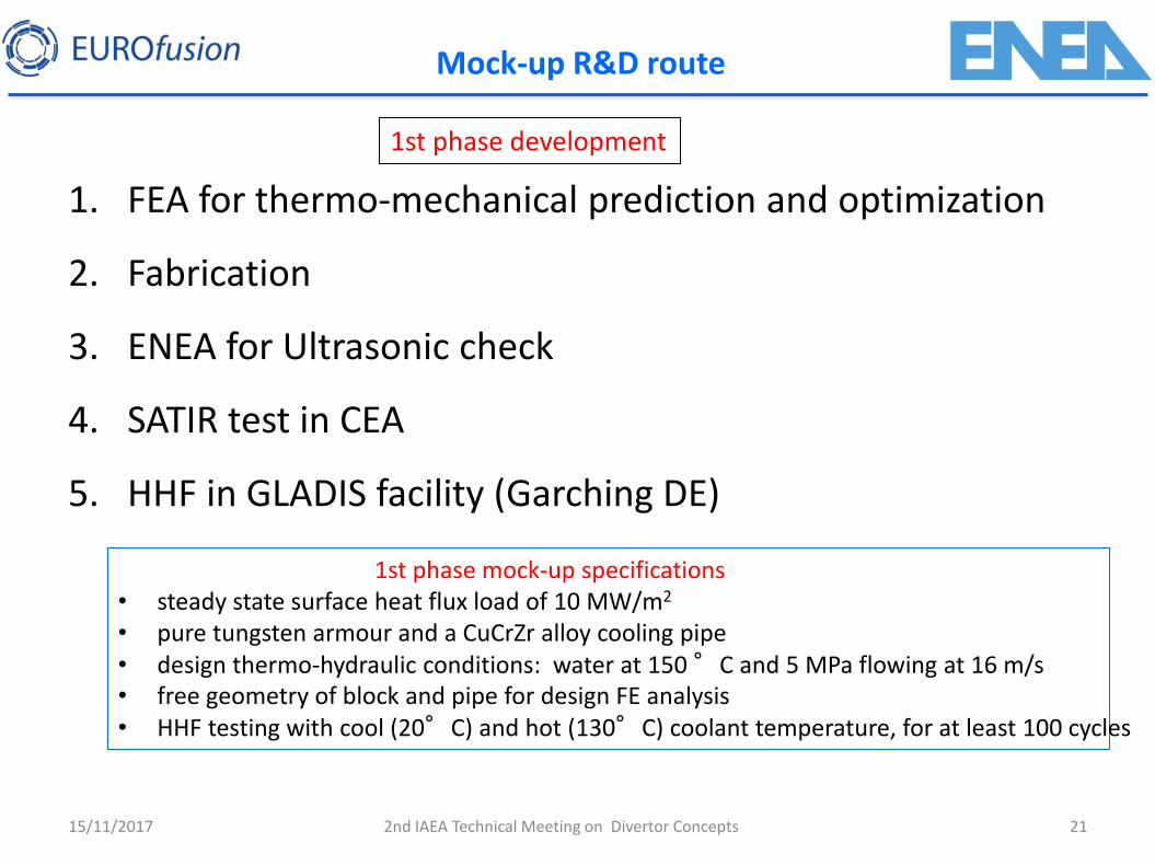
1. FEA for thermo-mechanical prediction and optimization
2. Fabrication
3. ENEA for Ultrasonic check
4. SATIR test in CEA
5. HHF in GLADIS facility (Garching DE)
Mock-up R&D route
15/11/2017
1st phase development
1st phase mock-up specifications • steady state surface heat flux load of 10 MW/m2
• pure tungsten armour and a CuCrZr alloy cooling pipe • design thermo-hydraulic conditions: water at 150 °C and 5 MPa flowing at 16 m/s • free geometry of block and pipe for design FE analysis • HHF testing with cool (20°C) and hot (130°C) coolant temperature, for at least 100 cycles
2nd IAEA Technical Meeting on Divertor Concepts
22
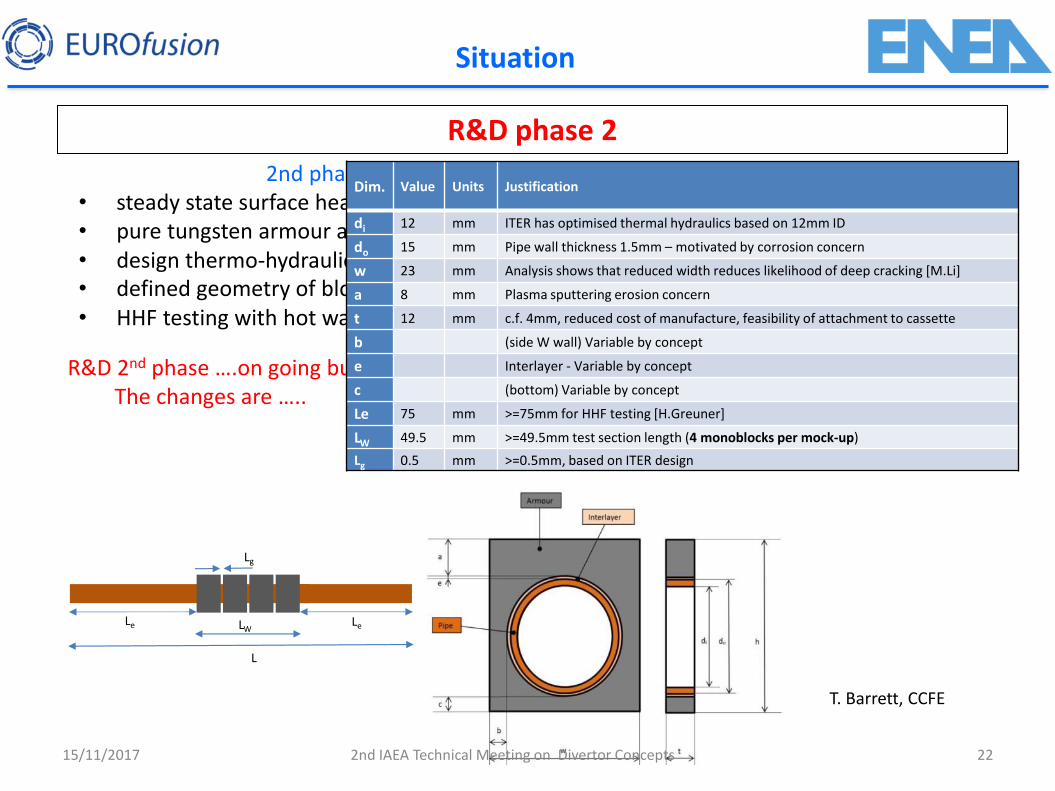
Situation
R&D phase 2
15/11/2017
R&D 2nd phase ….on going but changes on geometrical The changes are …..
2nd phase mock-up specifications • steady state surface heat flux of 20 MW/m2
• pure tungsten armour and a CuCrZr alloy cooling pipe • design thermo-hydraulic conditions water at 150 °C and 5 MPa flowing at 16 m/s • defined geometry of block and pipe for design analysis and manufacturing • HHF testing with hot water (130 °C, 4 MPa, 16 m/s, GLADIS)
Le LW
L
Le
Lg
Dim. Value Units Justification
di 12 mm ITER has optimised thermal hydraulics based on 12mm ID
do 15 mm Pipe wall thickness 1.5mm – motivated by corrosion concern
w 23 mm Analysis shows that reduced width reduces likelihood of deep cracking [M.Li]
a 8 mm Plasma sputtering erosion concern
t 12 mm c.f. 4mm, reduced cost of manufacture, feasibility of attachment to cassette
b (side W wall) Variable by concept
e Interlayer - Variable by concept
c (bottom) Variable by concept
Le 75 mm >=75mm for HHF testing [H.Greuner]
LW 49.5 mm >=49.5mm test section length (4 monoblocks per mock-up)
Lg 0.5 mm >=0.5mm, based on ITER design
T. Barrett, CCFE
2nd IAEA Technical Meeting on Divertor Concepts
23
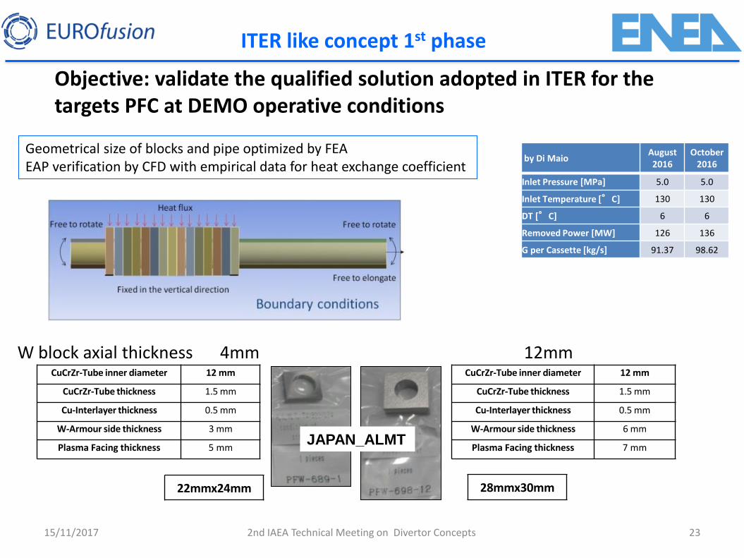
ITER like concept 1st phase
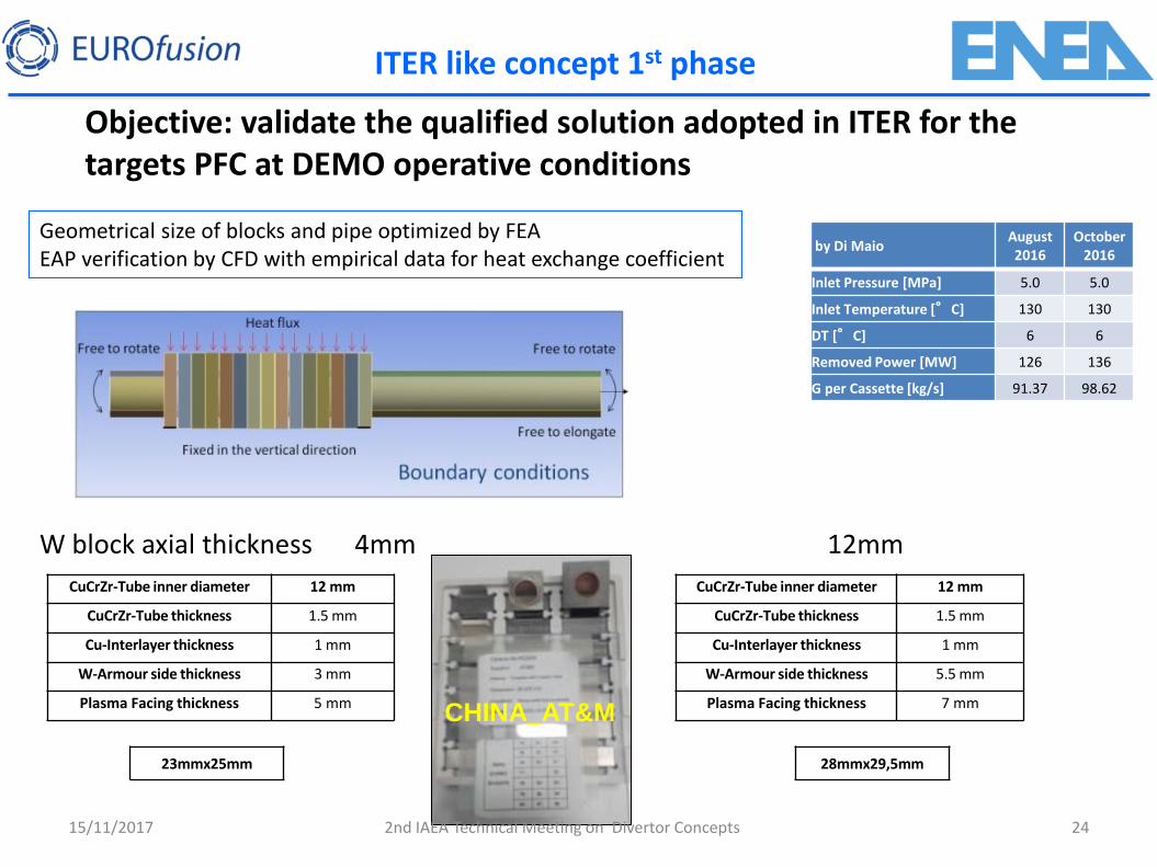
Objective: validate the qualified solution adopted in ITER for the targets PFC at DEMO operative conditions
15/11/2017
Geometrical size of blocks and pipe optimized by FEA EAP verification by CFD with empirical data for heat exchange coefficient
W block axial thickness 4mm 12mm
CuCrZr-Tube inner diameter 12 mm
CuCrZr-Tube thickness 1.5 mm
Cu-Interlayer thickness 0.5 mm
W-Armour side thickness 6 mm
Plasma Facing thickness 7 mm
CuCrZr-Tube inner diameter 12 mm
CuCrZr-Tube thickness 1.5 mm
Cu-Interlayer thickness 0.5 mm
W-Armour side thickness 3 mm
Plasma Facing thickness 5 mm
22mmx24mm 28mmx30mm
JAPAN_ALMT
2nd IAEA Technical Meeting on Divertor Concepts
by Di Maio August 2016
October 2016
Inlet Pressure [MPa] 5.0 5.0
Inlet Temperature [°C] 130 130
DT [°C] 6 6
Removed Power [MW] 126 136
G per Cassette [kg/s] 91.37 98.62
24
ITER like concept 1st phase
Objective: validate the qualified solution adopted in ITER for the targets PFC at DEMO operative conditions
15/11/2017
Geometrical size of blocks and pipe optimized by FEA EAP verification by CFD with empirical data for heat exchange coefficient
W block axial thickness 4mm 12mm
CuCrZr-Tube inner diameter 12 mm
CuCrZr-Tube thickness 1.5 mm
Cu-Interlayer thickness 1 mm
W-Armour side thickness 5.5 mm
Plasma Facing thickness 7 mm
CuCrZr-Tube inner diameter 12 mm
CuCrZr-Tube thickness 1.5 mm
Cu-Interlayer thickness 1 mm
W-Armour side thickness 3 mm
Plasma Facing thickness 5 mm
23mmx25mm 28mmx29,5mm
CHINA_AT&M
2nd IAEA Technical Meeting on Divertor Concepts
by Di Maio August 2016
October 2016
Inlet Pressure [MPa] 5.0 5.0
Inlet Temperature [°C] 130 130
DT [°C] 6 6
Removed Power [MW] 126 136
G per Cassette [kg/s] 91.37 98.62

25
ITER like concept 1st phase
Monoblock design: CuCrZr tube 12mm ID, 1.5mm thick Two geometries ITER-like optimized 12 mm axial thickness DEMO design 4 mm axial thickness
W-blocks ALM&T Japan blocks + ENEA Cu-cast interlayer AT&M China blocks (after FEA optimization) + HIP Cu interlayer
#9 #11 #12
#5
#7
#8
Pipe to block joined by HRP
15/11/2017 2nd IAEA Technical Meeting on Divertor Concepts
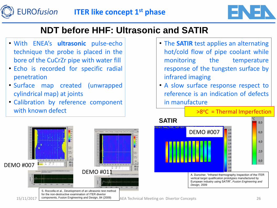
NDT before HHF: Ultrasonic and SATIR
DEMO #007
A. Durocher, “Infrared thermography inspection of the ITER
vertical target qualification prototypes manufactured by
European industry using SATIR”, Fusion Engineering and Design, 2009
15/11/2017 26 2nd IAEA Technical Meeting on Divertor Concepts
ITER like concept 1st phase
SATIR
• The SATIR test applies an alternating hot/cold flow of pipe coolant while monitoring the temperature response of the tungsten surface by infrared imaging
• A slow surface response respect to reference is an indication of defects in manufacture
• With ENEA’s ultrasonic pulse-echo technique the probe is placed in the bore of the CuCrZr pipe with water fill
• Echo is recorded for specific radial penetration
• Surface map created (unwrapped cylindrical map) at joints
• Calibration by reference component with known defect
DEMO #007
DEMO #011
>8oC = Thermal Imperfection
S. Roccella et al., Development of an ultrasonic test method
for the non-destructive examination of ITER divertor components, Fusion Engineering and Design, 84 (2009)
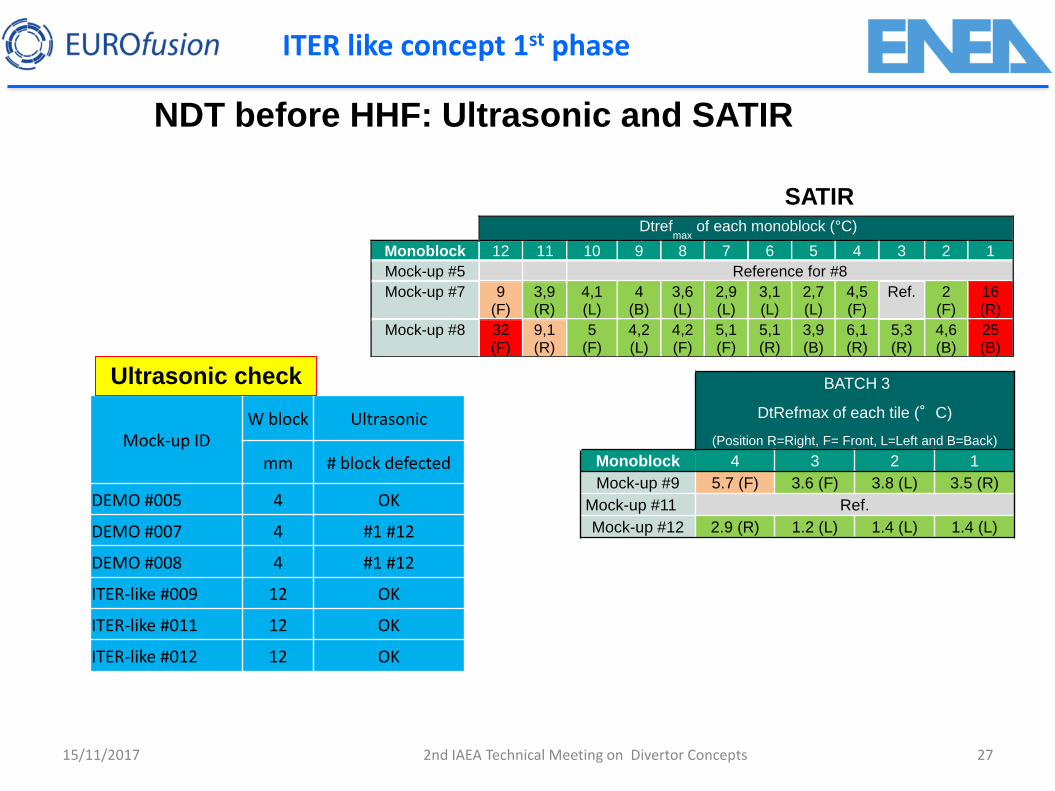
NDT before HHF: Ultrasonic and SATIR
Dtrefmax
of each monoblock (°C)
Monoblock 12 11 10 9 8 7 6 5 4 3 2 1
Mock-up #5 Reference for #8
Mock-up #7 9 (F)
3,9 (R)
4,1 (L)
4 (B)
3,6 (L)
2,9 (L)
3,1 (L)
2,7 (L)
4,5 (F)
Ref. 2 (F)
16 (R)
Mock-up #8 32 (F)
9,1 (R)
5 (F)
4,2 (L)
4,2 (F)
5,1 (F)
5,1 (R)
3,9 (B)
6,1 (R)
5,3 (R)
4,6 (B)
25 (B)
15/11/2017 27 2nd IAEA Technical Meeting on Divertor Concepts
ITER like concept 1st phase
SATIR
Mock-up ID W block Ultrasonic
mm # block defected
DEMO #005 4 OK
DEMO #007 4 #1 #12
DEMO #008 4 #1 #12
ITER-like #009 12 OK
ITER-like #011 12 OK
ITER-like #012 12 OK
Ultrasonic check
BATCH 3
DtRefmax of each tile (°C)
(Position R=Right, F= Front, L=Left and B=Back)
Monoblock 4 3 2 1
Mock-up #9 5.7 (F) 3.6 (F) 3.8 (L) 3.5 (R)
Mock-up #11 Ref.
Mock-up #12 2.9 (R) 1.2 (L) 1.4 (L) 1.4 (L)

HHF tests in GLADIS
First PHASE HHF -> cold water (20°C, 10 bar, 12 m/s)
15/11/2017 28 2nd IAEA Technical Meeting on Divertor Concepts
Mock-up ID W block Pipe screening Cycling
SATIR Ultrasonic HHF mm ID/OD mm MW/m² n° MW/m²
DEMO #005 4 12/15 20 100 10 OK OK no defect
DEMO #007 4 12/15 20 100 10 OK OK 1 defect
DEMO #008 4 12/15 20 OK OK Hot spots
ITER-like #009 12 12/15 20 100 15 OK OK no defect
ITER-like #011 12 12/15 20 100 10 OK OK no defect
ITER-like #012 12 12/15 20 100 10 OK OK no defect
SECOND PHASE HHF -> hot water (130°C, 40 bar, 16 m/s)
Mock-up ID W block Pipe screening Cycling
SATIR Ultrasonic HHF mm ID/OD mm MW/m² n° MW/m²
DEMO #005 4 12/15 6-20 300 20 OK OK no defect
ITER-like #011 12 12/15 6-20 300 20 OK OK no defect
ITER like concept 1st phase
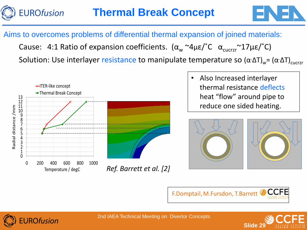
Thermal Break Concept
Slide 29
Aims to overcomes problems of differential thermal expansion of joined materials:
Cause: 4:1 Ratio of expansion coefficients. (αw ~4με/˚C αcucrzr~17με/˚C)
Solution: Use interlayer resistance to manipulate temperature so (α.ΔT)w= (α.ΔT)cucrzr
• Also Increased interlayer
thermal resistance deflects heat “flow” around pipe to reduce one sided heating.
0123456789
10111213
0 200 400 600 800 1000
Ra
dia
l d
ista
nce
/m
m
Temperature / degC
ITER-like concept
Thermal Break Concept
Ref. Barrett et al. [2]
F.Domptail, M.Fursdon, T.Barrett
2nd IAEA Technical Meeting on Divertor Concepts
Slide 30
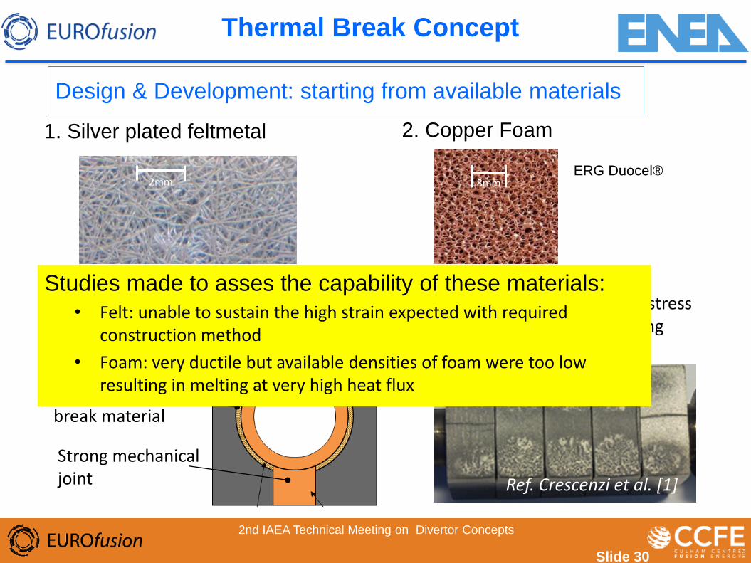
1. Silver plated feltmetal 2. Copper Foam
• Construction
Strong mechanical joint
Soft Thermal break material
Split tungsten relieves pipe stress and anticipates deep cracking “failure” mode.
2mm
Tungsten blocks in 2 halves
8mm ERG Duocel®
Ref. Crescenzi et al. [1]
Studies made to asses the capability of these materials:
• Felt: unable to sustain the high strain expected with required construction method
• Foam: very ductile but available densities of foam were too low resulting in melting at very high heat flux
Design & Development: starting from available materials
2nd IAEA Technical Meeting on Divertor Concepts
Thermal Break Concept
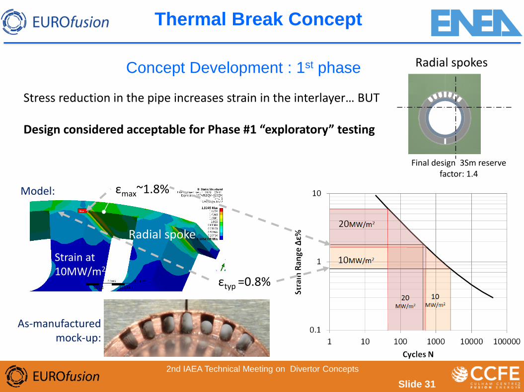
Concept Development : 1st phase
Stress reduction in the pipe increases strain in the interlayer… BUT Design considered acceptable for Phase #1 “exploratory” testing
Radial spoke
Strain at 10MW/m2
εmax~1.8%
εtyp =0.8%
Radial spokes
Final design 3Sm reserve factor: 1.4
As-manufactured mock-up:
Model:
Slide 31
2nd IAEA Technical Meeting on Divertor Concepts
Thermal Break Concept
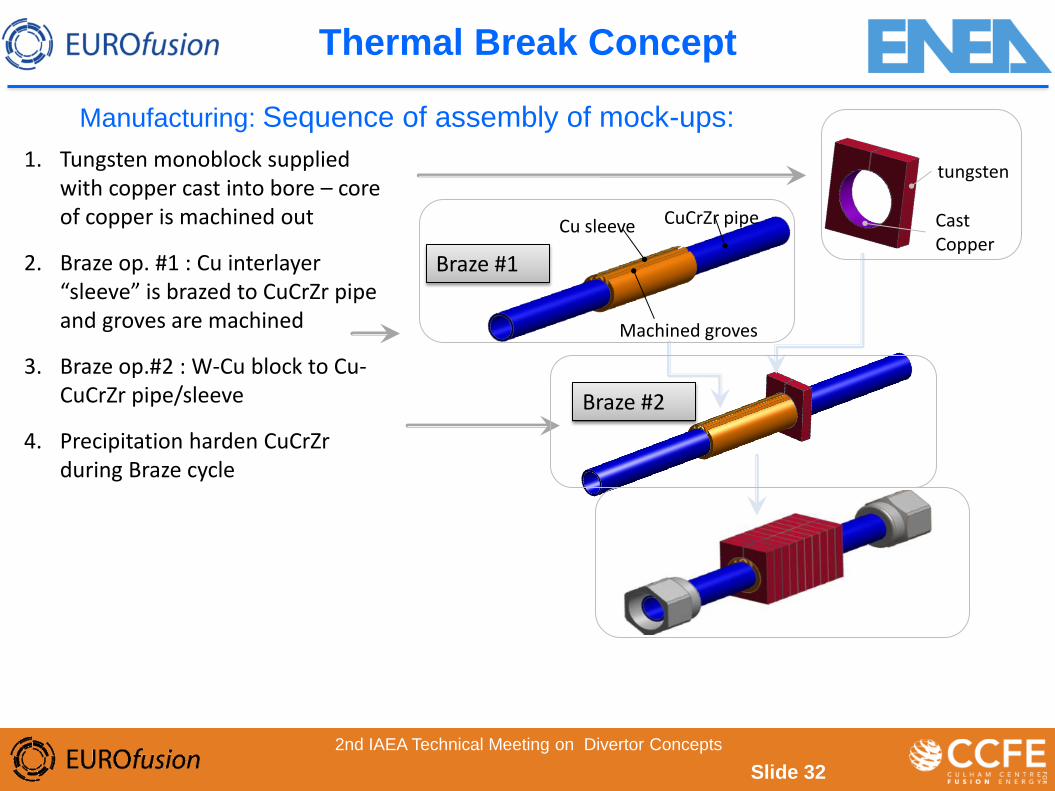
1. Tungsten monoblock supplied with copper cast into bore – core of copper is machined out
2. Braze op. #1 : Cu interlayer “sleeve” is brazed to CuCrZr pipe and groves are machined
3. Braze op.#2 : W-Cu block to Cu-CuCrZr pipe/sleeve
4. Precipitation harden CuCrZr during Braze cycle
Manufacturing: Sequence of assembly of mock-ups:
tungsten
Cast Copper
Cu sleeve CuCrZr pipe
Machined groves
Braze #2
Braze #1
Slide 32
2nd IAEA Technical Meeting on Divertor Concepts
Thermal Break Concept
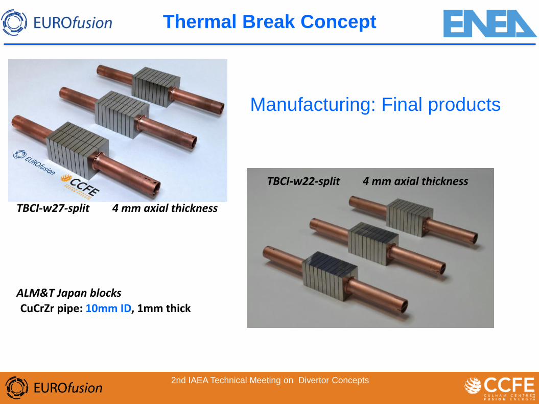
Manufacturing: Final products
TBCI-w27-split 4 mm axial thickness
ALM&T Japan blocks
CuCrZr pipe: 10mm ID, 1mm thick
2nd IAEA Technical Meeting on Divertor Concepts
TBCI-w22-split 4 mm axial thickness
Thermal Break Concept
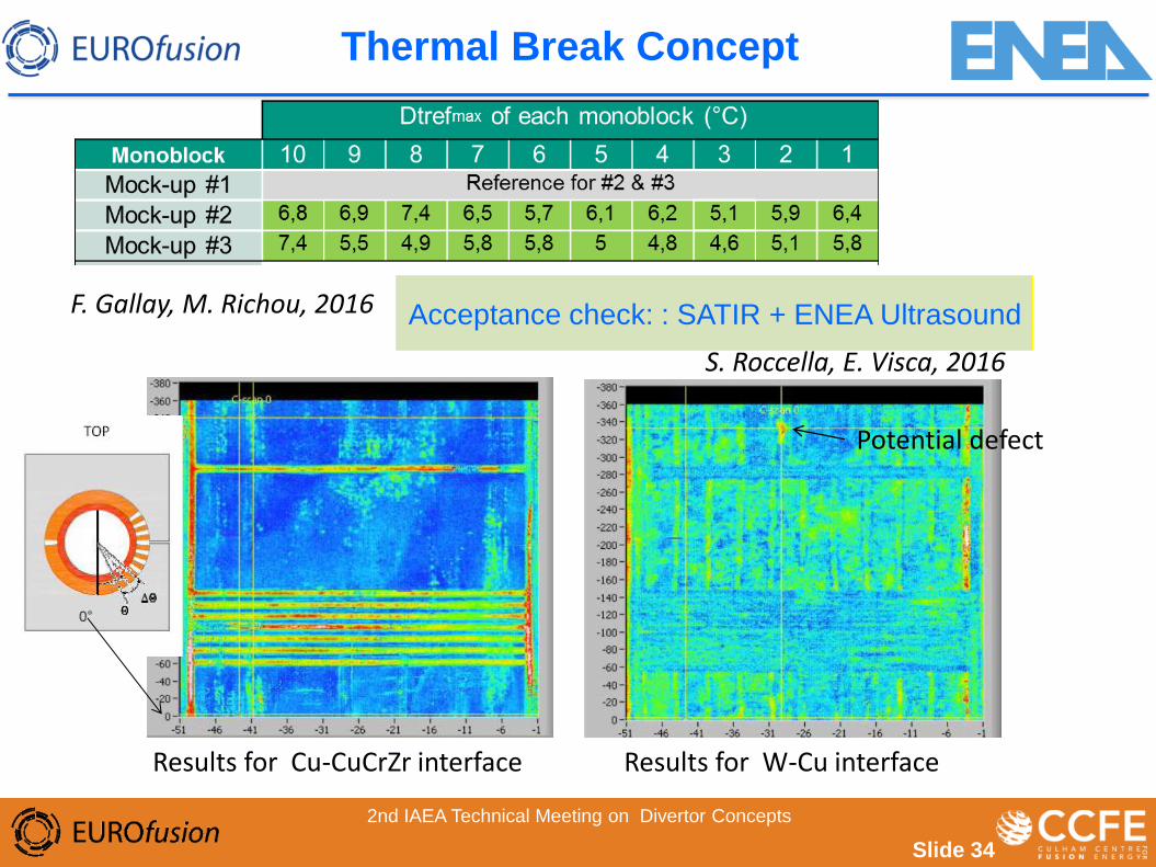
Acceptance check: : SATIR + ENEA Ultrasound
Slide 34
Results for Cu-CuCrZr interface
Potential defect
Results for W-Cu interface
S. Roccella, E. Visca, 2016
2nd IAEA Technical Meeting on Divertor Concepts
F. Gallay, M. Richou, 2016
Thermal Break Concept
W/Cu composite concept
15/11/2017 35 2nd IAEA Technical Meeting on Divertor Concepts
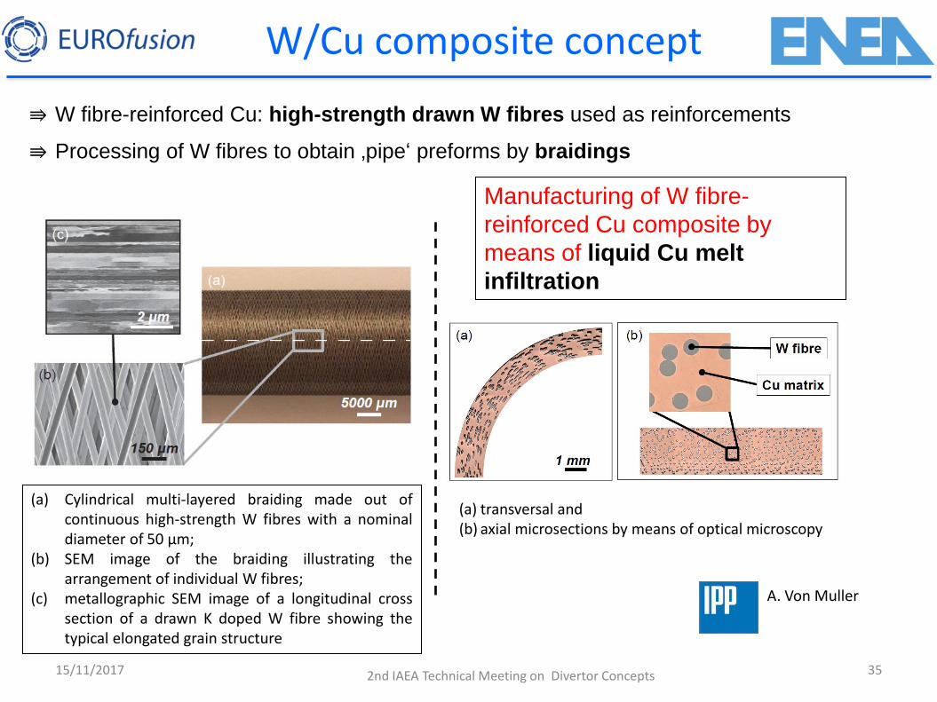
⇛ Processing of W fibres to obtain ‚pipe‘ preforms by braidings
⇛ W fibre-reinforced Cu: high-strength drawn W fibres used as reinforcements
(a) Cylindrical multi-layered braiding made out of continuous high-strength W fibres with a nominal diameter of 50 μm;
(b) SEM image of the braiding illustrating the arrangement of individual W fibres;
(c) metallographic SEM image of a longitudinal cross section of a drawn K doped W fibre showing the typical elongated grain structure
(a) transversal and (b) axial microsections by means of optical microscopy
Manufacturing of W fibre-
reinforced Cu composite by
means of liquid Cu melt
infiltration
A. Von Muller

W fibre-reinforced Cu
Necking of W fibres plainly visible with ductile failure of both Cu matrix
& W fibrous reinforcements (already at room temperature)
SEM fracture surface images of a W fibre-reinforced Cu pipe specimen (Cu infiltrated
W fibre braiding); after axial tensile test of pipe at room temperature
100 µm
36 15/11/2017 2nd IAEA Technical Meeting on Divertor Concepts
A. Von Muller
W/Cu composite concept
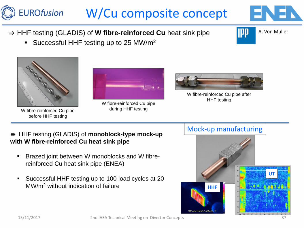
Mock-up manufacturing
15/11/2017 37 2nd IAEA Technical Meeting on Divertor Concepts
⇛ HHF testing (GLADIS) of W fibre-reinforced Cu heat sink pipe
Successful HHF testing up to 25 MW/m2
W fibre-reinforced Cu pipe
before HHF testing
W fibre-reinforced Cu pipe
during HHF testing
W fibre-reinforced Cu pipe after
HHF testing
⇛ HHF testing (GLADIS) of monoblock-type mock-up
with W fibre-reinforced Cu heat sink pipe
Brazed joint between W monoblocks and W fibre-
reinforced Cu heat sink pipe (ENEA)
Successful HHF testing up to 100 load cycles at 20
MW/m2 without indication of failure
UT
HHF
A. Von Muller
W/Cu composite concept
38
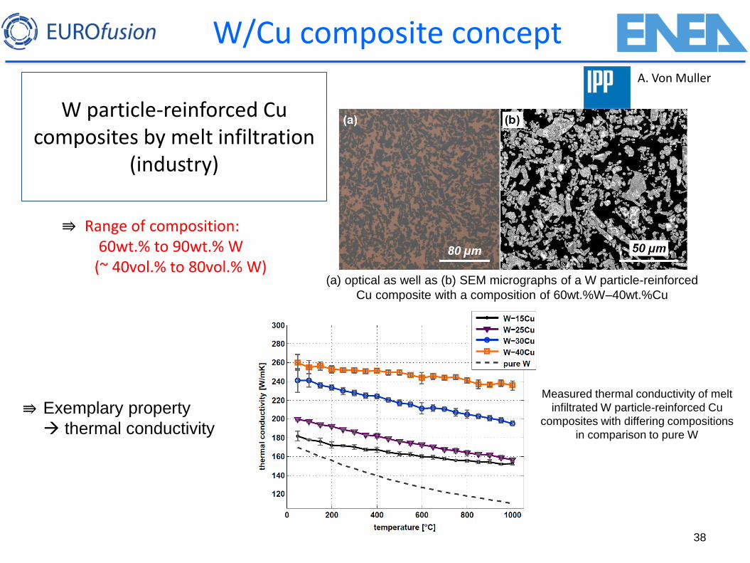
W particle-reinforced Cu composites by melt infiltration
(industry)
⇛ Exemplary property
thermal conductivity
⇛ Range of composition: 60wt.% to 90wt.% W
(~ 40vol.% to 80vol.% W) (a) optical as well as (b) SEM micrographs of a W particle-reinforced
Cu composite with a composition of 60wt.%W–40wt.%Cu
Measured thermal conductivity of melt
infiltrated W particle-reinforced Cu
composites with differing compositions
in comparison to pure W
A. Von Muller
W/Cu composite concept
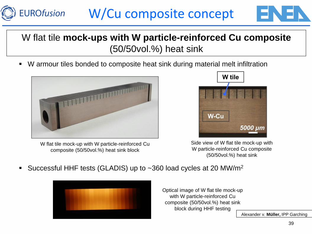
39
W flat tile mock-ups with W particle-reinforced Cu composite
(50/50vol.%) heat sink
Successful HHF tests (GLADIS) up to ~360 load cycles at 20 MW/m2
W armour tiles bonded to composite heat sink during material melt infiltration
W flat tile mock-up with W particle-reinforced Cu
composite (50/50vol.%) heat sink block
Side view of W flat tile mock-up with
W particle-reinforced Cu composite
(50/50vol.%) heat sink
Optical image of W flat tile mock-up
with W particle-reinforced Cu
composite (50/50vol.%) heat sink
block during HHF testing Alexander v. Müller, IPP Garching
W/Cu composite concept
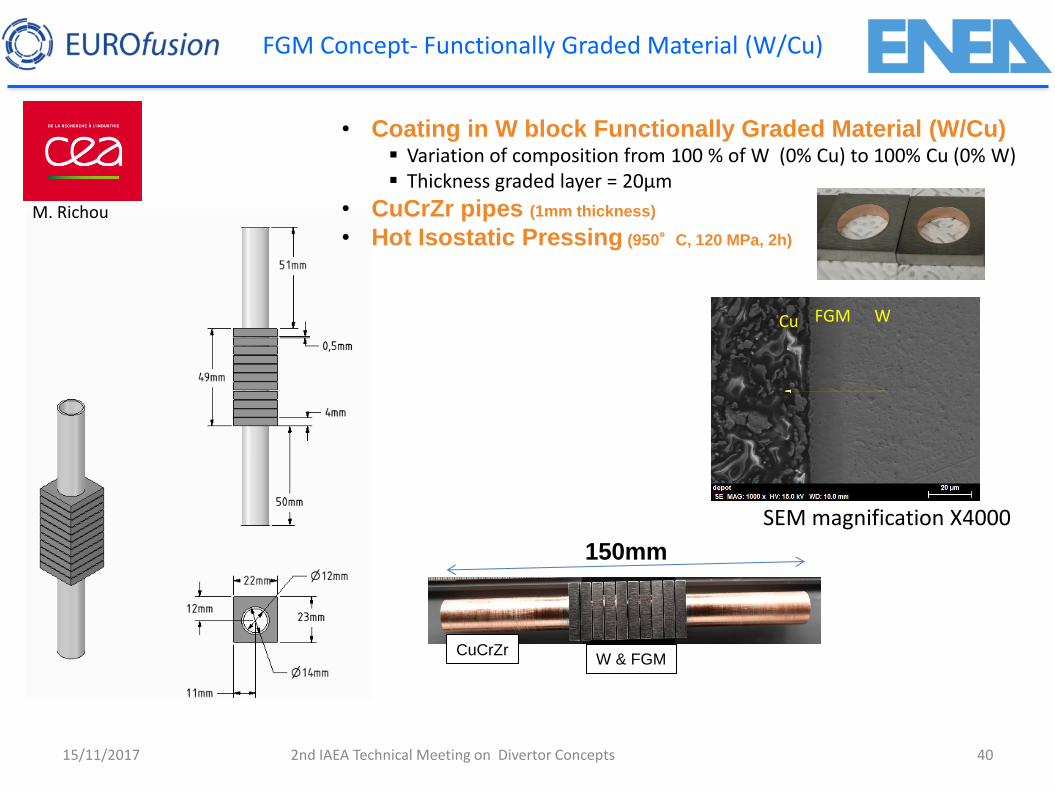
FGM Concept- Functionally Graded Material (W/Cu)
40
• Coating in W block Functionally Graded Material (W/Cu) Variation of composition from 100 % of W (0% Cu) to 100% Cu (0% W) Thickness graded layer = 20µm
• CuCrZr pipes (1mm thickness)
• Hot Isostatic Pressing (950°C, 120 MPa, 2h)
150mm
CuCrZr W & FGM
SEM magnification X4000
FGM W
15/11/2017 2nd IAEA Technical Meeting on Divertor Concepts
M. Richou
Cu
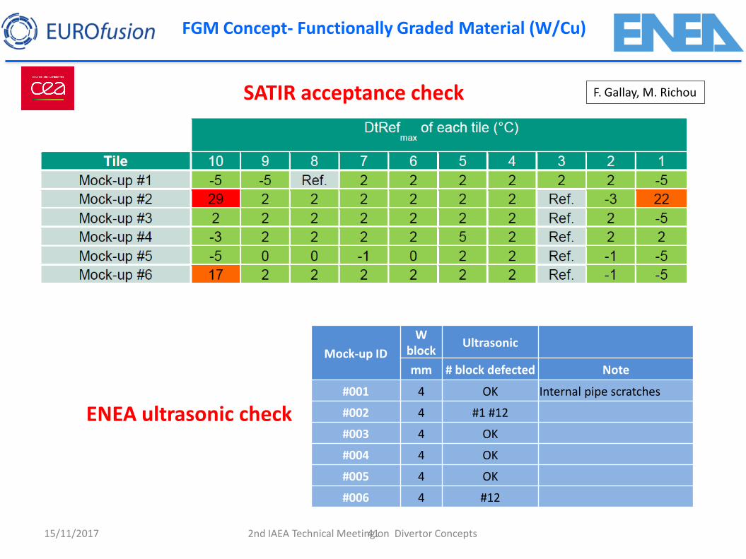
41
SATIR acceptance check
15/11/2017 2nd IAEA Technical Meeting on Divertor Concepts
F. Gallay, M. Richou
Mock-up ID
W block
Ultrasonic
mm # block defected Note
#001 4 OK Internal pipe scratches
#002 4 #1 #12
#003 4 OK
#004 4 OK
#005 4 OK
#006 4 #12
ENEA ultrasonic check
FGM Concept- Functionally Graded Material (W/Cu)
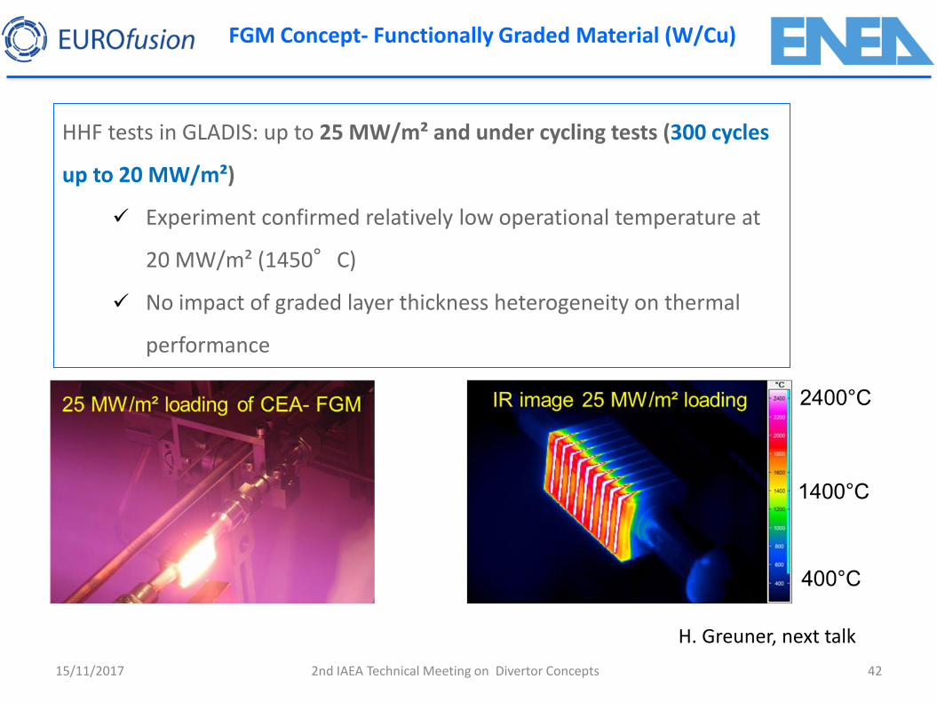
15/11/2017 2nd IAEA Technical Meeting on Divertor Concepts 42
HHF tests in GLADIS: up to 25 MW/m² and under cycling tests (300 cycles
up to 20 MW/m²)
Experiment confirmed relatively low operational temperature at
20 MW/m² (1450°C)
No impact of graded layer thickness heterogeneity on thermal
performance
H. Greuner, next talk
FGM Concept- Functionally Graded Material (W/Cu)
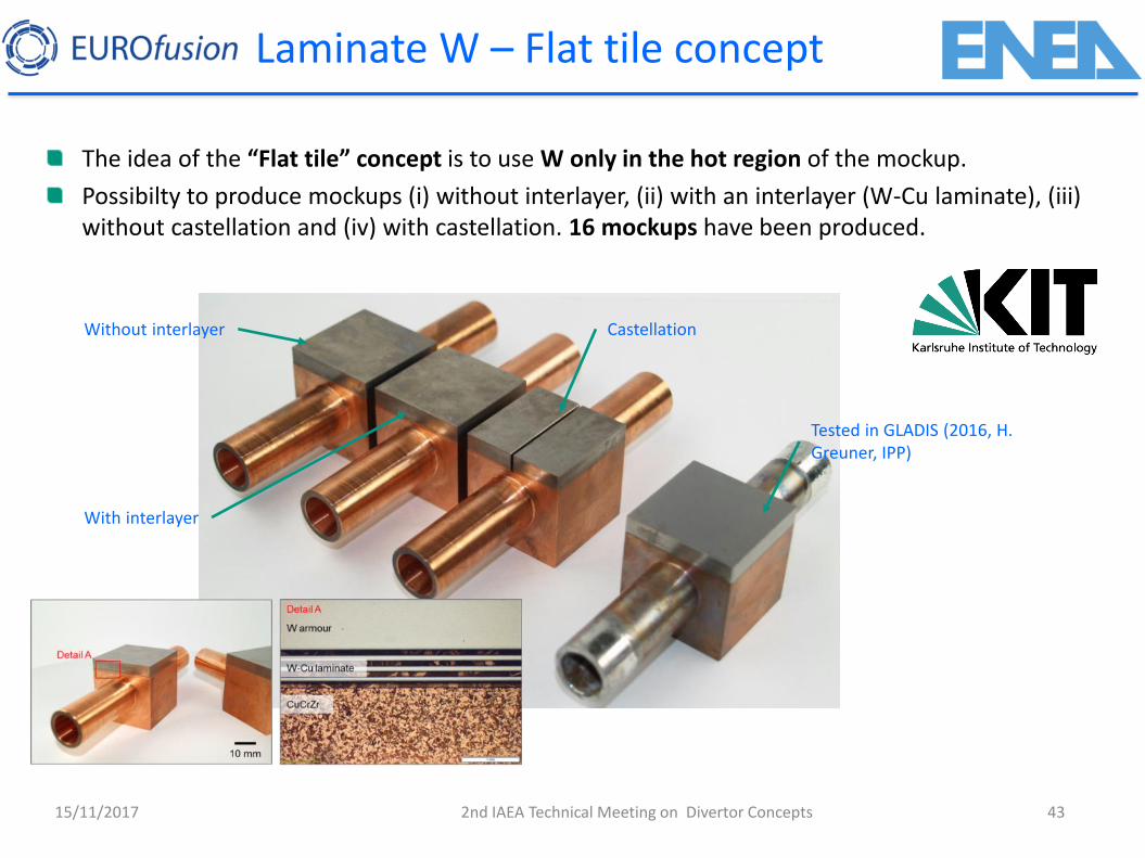
Laminate W – Flat tile concept
The idea of the “Flat tile” concept is to use W only in the hot region of the mockup.
Possibilty to produce mockups (i) without interlayer, (ii) with an interlayer (W-Cu laminate), (iii) without castellation and (iv) with castellation. 16 mockups have been produced.
Castellation
Tested in GLADIS (2016, H. Greuner, IPP)
Without interlayer
With interlayer
15/11/2017 43 2nd IAEA Technical Meeting on Divertor Concepts
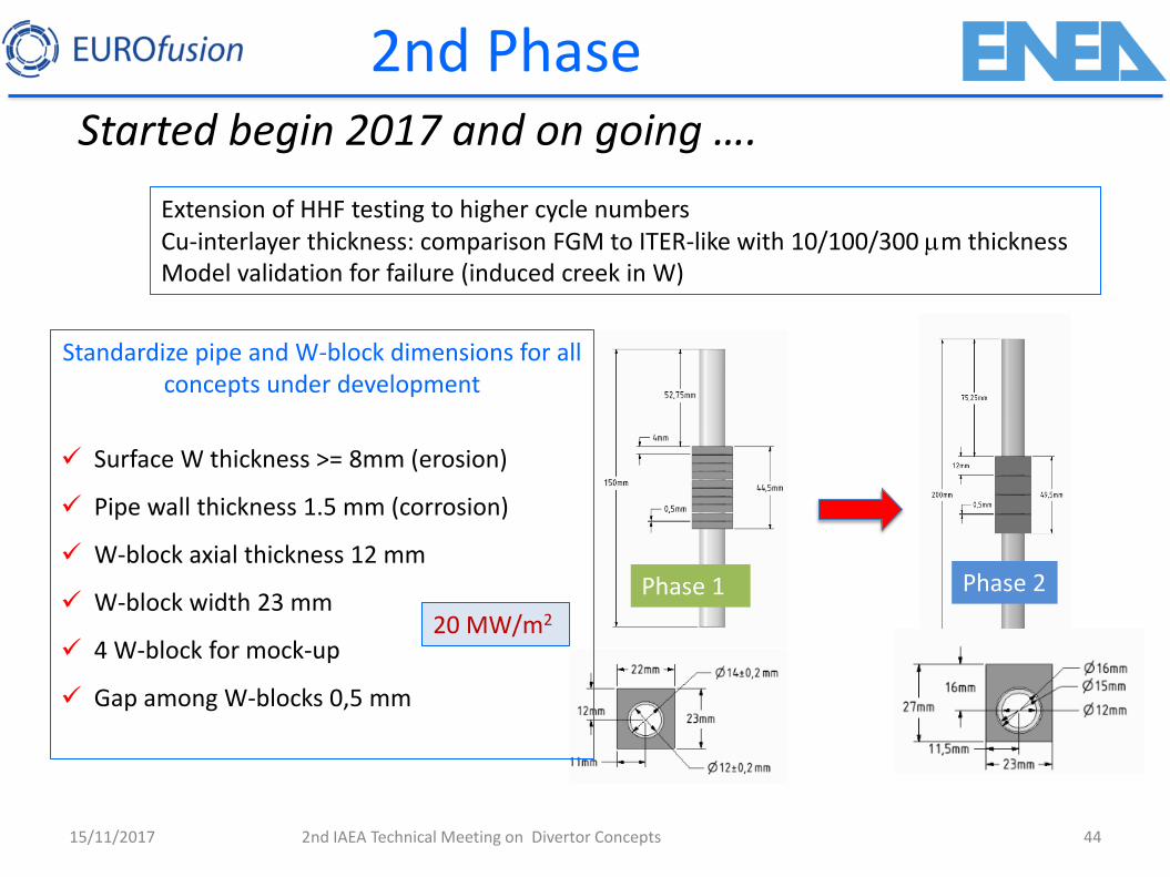
2nd Phase Started begin 2017 and on going ….
15/11/2017 2nd IAEA Technical Meeting on Divertor Concepts 44
Extension of HHF testing to higher cycle numbers Cu-interlayer thickness: comparison FGM to ITER-like with 10/100/300 mm thickness Model validation for failure (induced creek in W)
Standardize pipe and W-block dimensions for all concepts under development
Surface W thickness >= 8mm (erosion)
Pipe wall thickness 1.5 mm (corrosion)
W-block axial thickness 12 mm
W-block width 23 mm
4 W-block for mock-up
Gap among W-blocks 0,5 mm
Phase 1 Phase 2
20 MW/m2
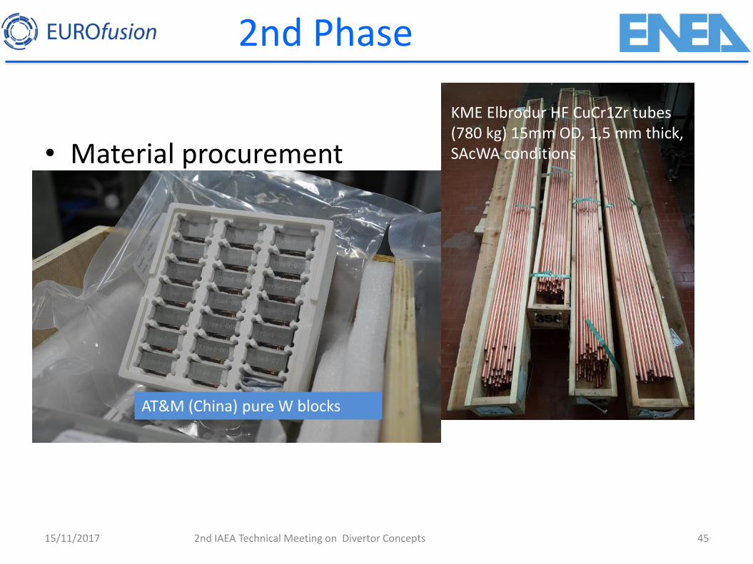
2nd Phase
15/11/2017 2nd IAEA Technical Meeting on Divertor Concepts 45
• Material procurement
• Developing of design tools for prediction
• Manufacturing of preliminary samples
• Fabrication of standard mockups
• ND checks by Ultrasonic and SATIR
• HHF testing in GLADIS
KME Elbrodur HF CuCr1Zr tubes (780 kg) 15mm OD, 1,5 mm thick, SAcWA conditions
AT&M (China) pure W blocks
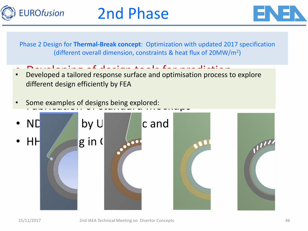
2nd Phase
15/11/2017 2nd IAEA Technical Meeting on Divertor Concepts 46
• Material procurement
• Developing of design tools for prediction
• Manufacturing of preliminary samples
• Fabrication of standard mockups
• ND checks by Ultrasonic and SATIR
• HHF testing in GLADIS
Phase 2 Design for Thermal-Break concept: Optimization with updated 2017 specification (different overall dimension, constraints & heat flux of 20MW/m2)
• Developed a tailored response surface and optimisation process to explore different design efficiently by FEA
• Some examples of designs being explored:
2nd Phase
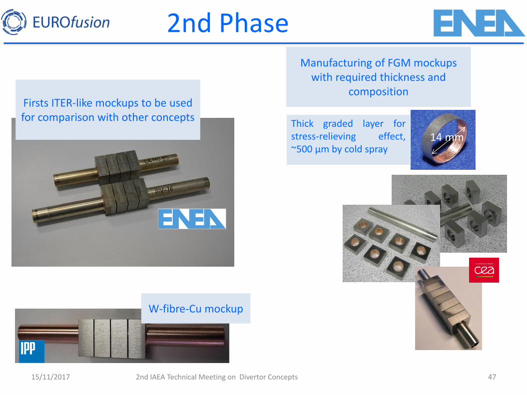
15/11/2017 2nd IAEA Technical Meeting on Divertor Concepts 47
Thick graded layer for stress-relieving effect, ~500 µm by cold spray
Manufacturing of FGM mockups with required thickness and
composition
14 mm
W-fibre-Cu mockup
Firsts ITER-like mockups to be used for comparison with other concepts
Conclusions
15/11/2017 2nd IAEA Technical Meeting on Divertor Concepts 48
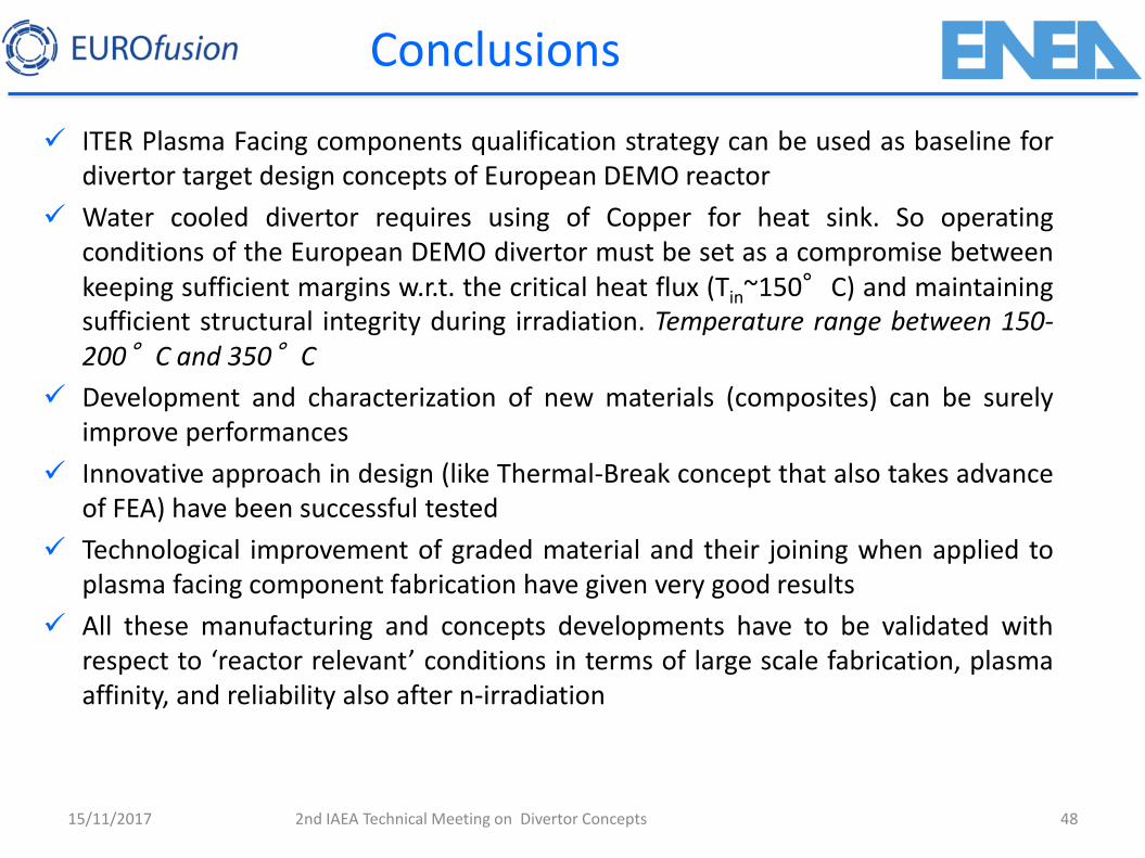
ITER Plasma Facing components qualification strategy can be used as baseline for divertor target design concepts of European DEMO reactor
Water cooled divertor requires using of Copper for heat sink. So operating conditions of the European DEMO divertor must be set as a compromise between keeping sufficient margins w.r.t. the critical heat flux (Tin~150°C) and maintaining sufficient structural integrity during irradiation. Temperature range between 150-200°C and 350°C
Development and characterization of new materials (composites) can be surely improve performances
Innovative approach in design (like Thermal-Break concept that also takes advance of FEA) have been successful tested
Technological improvement of graded material and their joining when applied to plasma facing component fabrication have given very good results
All these manufacturing and concepts developments have to be validated with respect to ‘reactor relevant’ conditions in terms of large scale fabrication, plasma affinity, and reliability also after n-irradiation
Thank you for your attention
15/11/2017 2nd IAEA Technical Meeting on Divertor Concepts
50
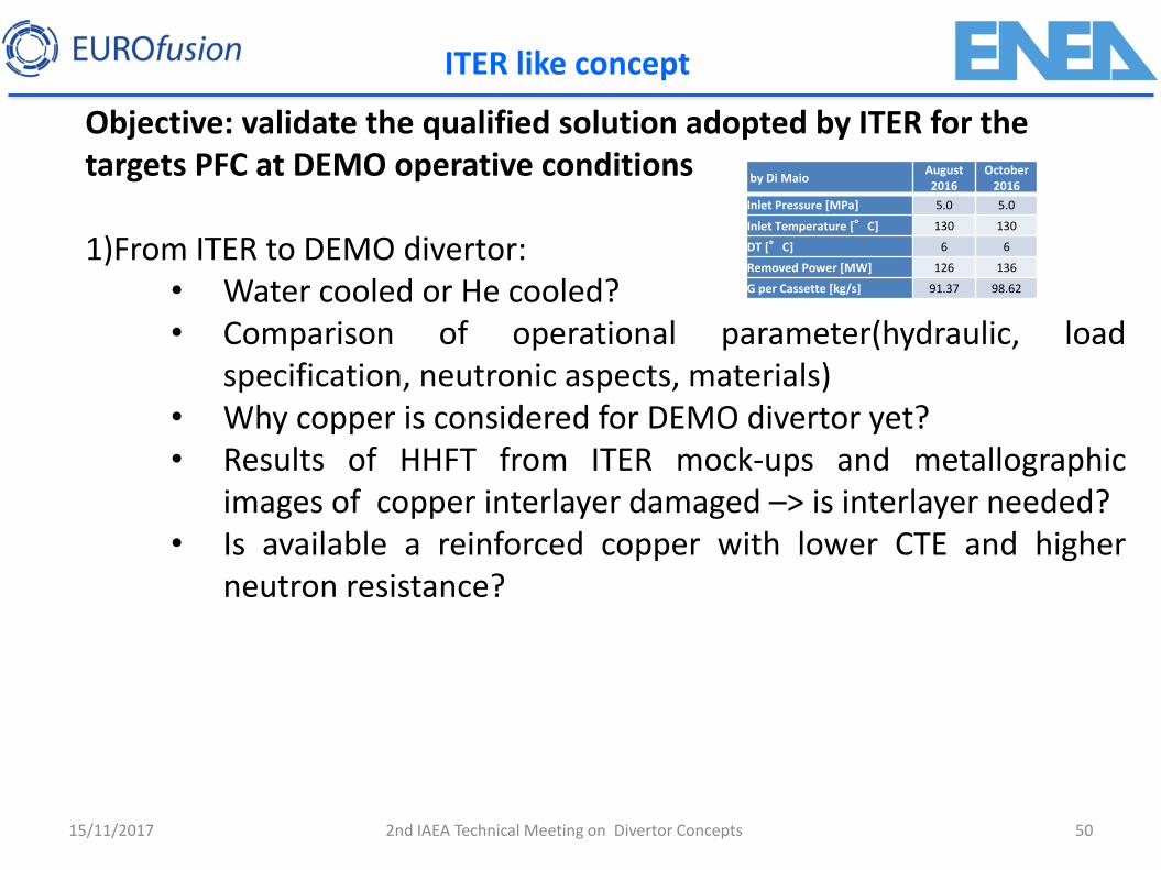
ITER like concept
Objective: validate the qualified solution adopted by ITER for the targets PFC at DEMO operative conditions 1)From ITER to DEMO divertor:
• Water cooled or He cooled? • Comparison of operational parameter(hydraulic, load
specification, neutronic aspects, materials) • Why copper is considered for DEMO divertor yet? • Results of HHFT from ITER mock-ups and metallographic
images of copper interlayer damaged –> is interlayer needed? • Is available a reinforced copper with lower CTE and higher
neutron resistance?
15/11/2017
by Di Maio August 2016
October 2016
Inlet Pressure [MPa] 5.0 5.0
Inlet Temperature [°C] 130 130
DT [°C] 6 6
Removed Power [MW] 126 136
G per Cassette [kg/s] 91.37 98.62
2nd IAEA Technical Meeting on Divertor Concepts
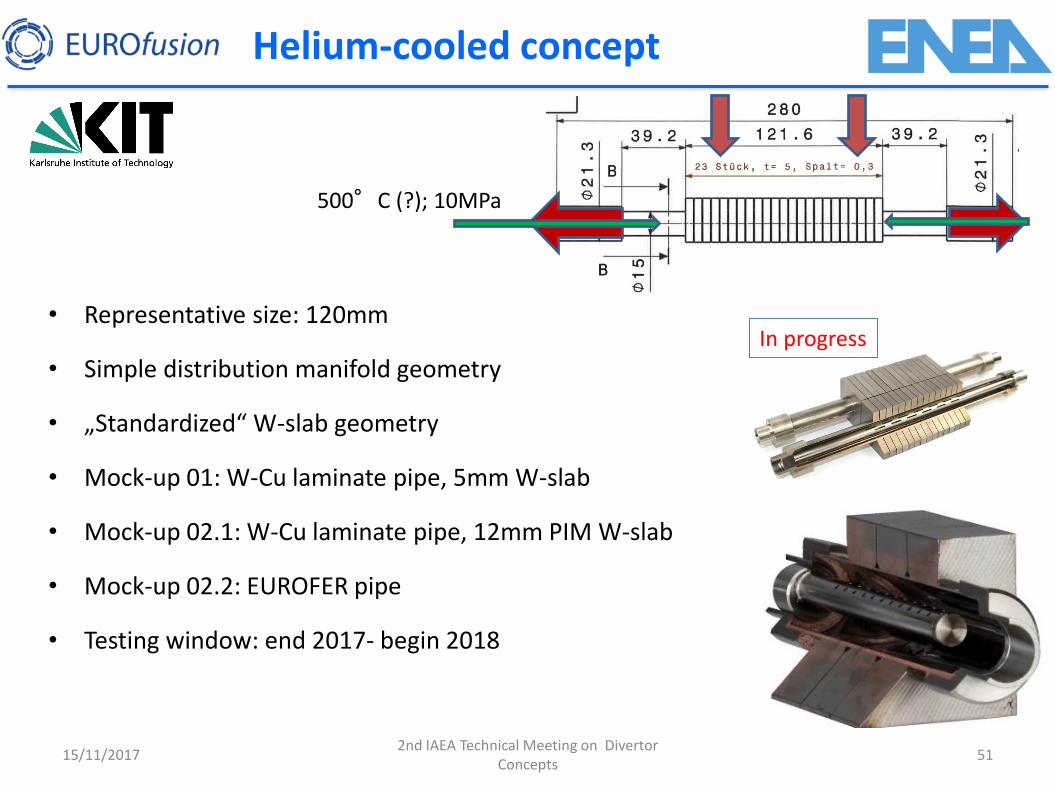
• Representative size: 120mm
• Simple distribution manifold geometry
• „Standardized“ W-slab geometry
• Mock-up 01: W-Cu laminate pipe, 5mm W-slab
• Mock-up 02.1: W-Cu laminate pipe, 12mm PIM W-slab
• Mock-up 02.2: EUROFER pipe
• Testing window: end 2017- begin 2018
500°C (?); 10MPa
In progress
Helium-cooled concept
15/11/2017 51 2nd IAEA Technical Meeting on Divertor
Concepts
15/11/2017 52
An additional critical issue in the design of water-cooled components is the transition from nucleate boiling (two-phase flow) to the boiling crisis or ‘burnout”. The burnout is characterized by the collapse of the heat transfer and the resulting sudden temperature excursion of the heated material. Cu based heat sink materials melt immediately. The threshold heat flux for this to occur is called the critical heat flux (CHF) [55,56]. Depending on the component design, the concentration of the heat-flux from the loaded surface to the inner cooling wall results in a peaked heat flux at the inner cooling wall and CHF could occur for moderate incident heat fluxes. The local CHF strongly depends on the coolant velocity, the coolant pressure, and the local coolant temperature. The coolant velocity is limited either by engineering constraints like erosion by corrosion of cooling tubes or by the pumping power needed to maintain the coolant flow. To achieve a sufficient safety margin against the CHF the inlet temperature has to be in the range of 150°C. [57] Therefore, the operating conditions of the divertor must be set as a compromise between keeping sufficient margins w.r.t. the critical heat flux (Tin~150°C) and maintaining sufficient structural integrity during irradiation. Traditional design rules for the case of Cu-alloy, based on the limited available irradiation data at relevant conditions, require operation in a temperature range between 150-200°C (to minimise radiation embrittlement) and 350°C, above which material properties deteriorate. A modern engineering design approach and design rules, to be further developed, instead of the conservative historical approaches, is required as there are numerous instances where low ductility occurs while the fracture toughness is high (see, e.g., [58]). Analyses should consider the full range of applicable situations including low ductility scenarios as well as crack propagation.
2nd IAEA Technical Meeting on Divertor Concepts