
Session 4: Interaction Region Subgroup Chairs: Fulvia ... · Session 4: Interaction Region Subgroup...
15
BNL Small Coil Test Winding Session 4: Interaction Region Subgroup Chairs: Fulvia Pilat, Tom Markiewicz (Tuesday afternoon) 1 cm LHeFlow Space CoilSupportTubes SextupoleCoil QuadrupoleCoilLayers ThermalShieldandCold MassSupportStructure QD0 e+ ∆ yoff 4.8 m
-
Upload
vuongkhanh -
Category
Documents
-
view
225 -
download
0
Transcript of Session 4: Interaction Region Subgroup Chairs: Fulvia ... · Session 4: Interaction Region Subgroup...

BNL Small Coil Test Winding
Session 4: Interaction Region SubgroupChairs: Fulvia Pilat, Tom Markiewicz(Tuesday afternoon)
1 cm
LHe Flow Space CoilSupportTubes
Sextupole Coil
Quadrupole CoilLayers Therm alShield and ColdM ass SupportStructure
QD0
e+ ∆
yoff
4.8 m

L inear C ollider F inal F ocusM agnetIssues (Top Level).
IR magnet des ign opt imiza t ion(beam aperture, field requirements,coil/pm–material layout, vacuum,energy deposition, support etc.).
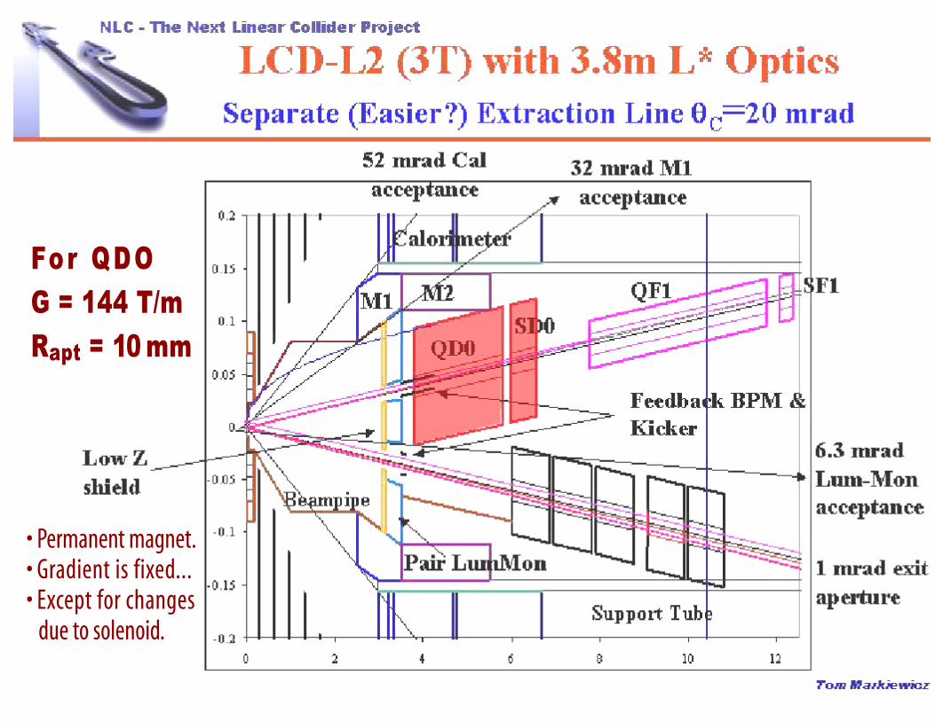
For Q D OG = 144 T/mRapt= 10m m
• Permanent magnet.• Gradient is fixed...• Except for changes
due to solenoid.

• Large aperture superconducting magnet(has both beams in the central region).
• Vertical extraction via electrostatic separatorat 20 m and a shielded septum at 50 m.
T he T E S L A and J L C F inalFocus Q uadrupole C oncepts.
• Iron magnet inside a superconductingcompensator magnet (avoid saturation,buck out detector solenoid field).
• Extract the beam through coil pocket.
IncomingBeam
ExtractedBeam
Y oke
57 mm
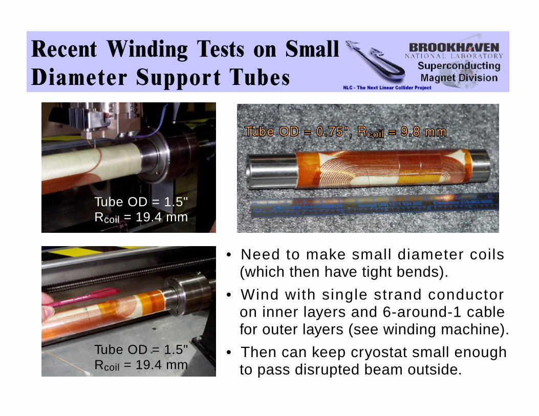
R ecent W inding Tests on S m allD iam eter S upport T ubes
Tube OD = 1.5"Rcoil = 19.4 mm
Tube OD = 1.5"Rcoil = 19.4 mm
• Need to make small diameter coils(which then have tight bends).
• Wind with single strand conductoron inner layers and 6-around-1 cablefor outer layers (see winding machine).
• Then can keep cryostat small enoughto pass disrupted beam outside.

S uperconducting M agnets forthe H E R A Lum inosity U pgrade.
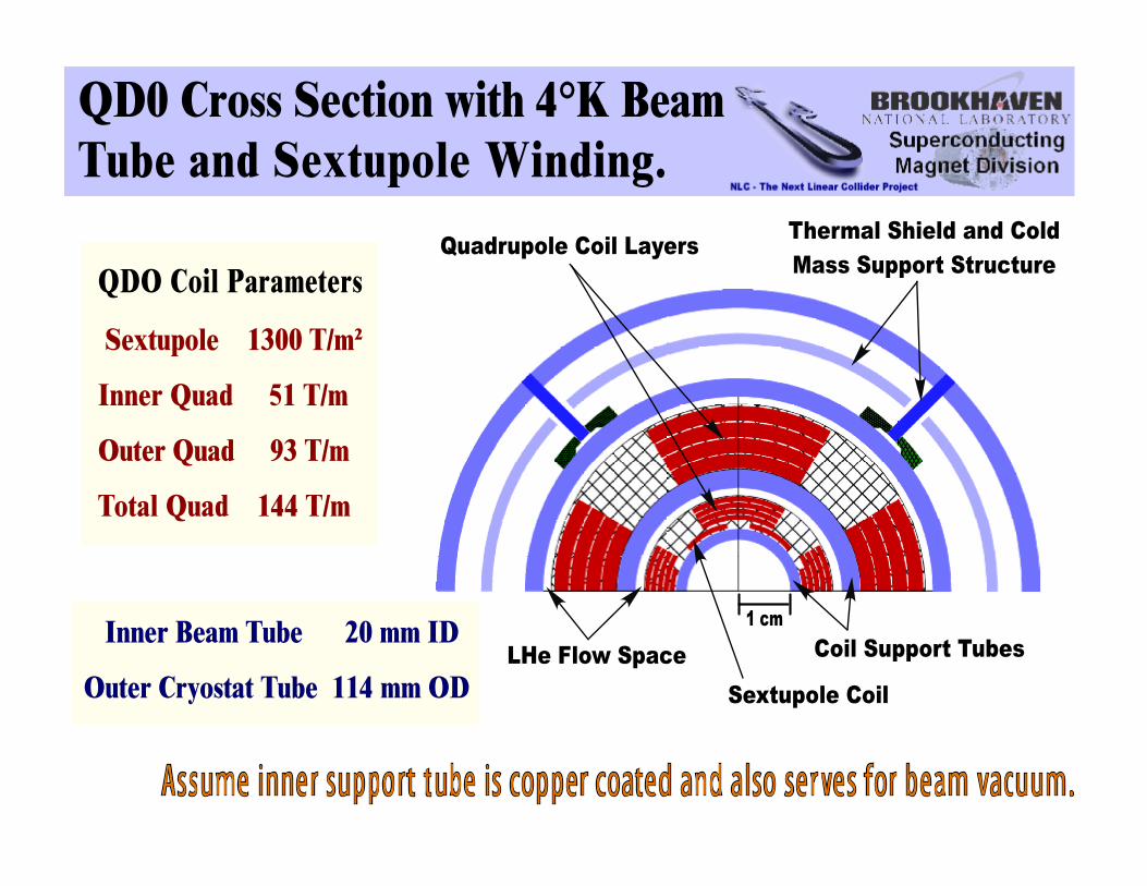
Q D 0 C ross Section w ith 4°K B eamT ube and S extupole W inding.
1 cm
LHe Flow Space CoilSupportTubes
Sextupole Coil
Quadrupole CoilLayers Therm alShield and ColdM ass SupportStructureQ D O C oilP aram eters
Sextupole 1300 T /m ²
Inner Q uad 51 T /m
O uter Q uad 93 T /m
TotalQ uad 144 T /m
Inner B eam T ube 20 m m ID
O uter C ryostatT ube 114 m m O D
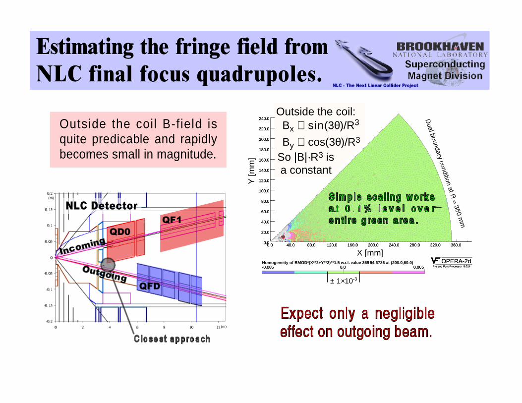
E stim ating the fringe field fromN L C finalfocus quadrupoles.
OPERA-2dPre and Post-Processor 8.014
OPERA-2dPre and Post-Processor 8.014
0.0 40.0 80.0 120.0 160.0 200.0 240.0 280.0 320.0 360.00.0
20.0
40.0
60.0
80.0
100.0
120.0
140.0
160.0
180.0
200.0
220.0
240.0
0.0 40.0 80.0 120.0 160.0 200.0 240.0 280.0 320.0 360.00.0
20.0
40.0
60.0
80.0
100.0
120.0
140.0
160.0
180.0
200.0
220.0
240.0
Y[m
m]
-0.005 0.0 0.005Homogeneity of BMOD*(X**2+Y**2)**1.5 w.r.t. value 369-0.005 0.0 0.005
54.6736 at (200.0,60.0)
X [mm]
± 1×10⁻³
Outside the coil:Bx ∝ sin(3θ)/R3
By ∝ cos(3θ)/R3
So |B|·R3 isa constant
Outside the coil B-field isquite predicable and rapidlybecomes small in magnitude.
NLC Detector
(m)
(m)

Tom Markiewicz
NLC -The NextLinearColliderProject
e+,e- pairs from beams. γ interactions
# pairs scalesw / Lum inosity
1-2x10 9/sec
0.85 m W perside
B S O L,L*,& M asks
Lum inosityM onitor & PairM onitor w illS hield Q D

Tom Markiewicz
NLC -The NextLinearColliderProject
e,γ,n secondaries made when pairs hithigh Z surface of LUM or Q1
High momentum pairsmostly in exit beampipe
Low momentum pairstrapped by detectorsolenoid field
160
0
0.03
0.06
0.09
0.12
00 200 400 600 800
40
80
120
.(km
)
D(m
)
x y D x
βN L C B eam D elivery S ystem :F inalFocus O ptics S um m ary.
Distance (m)
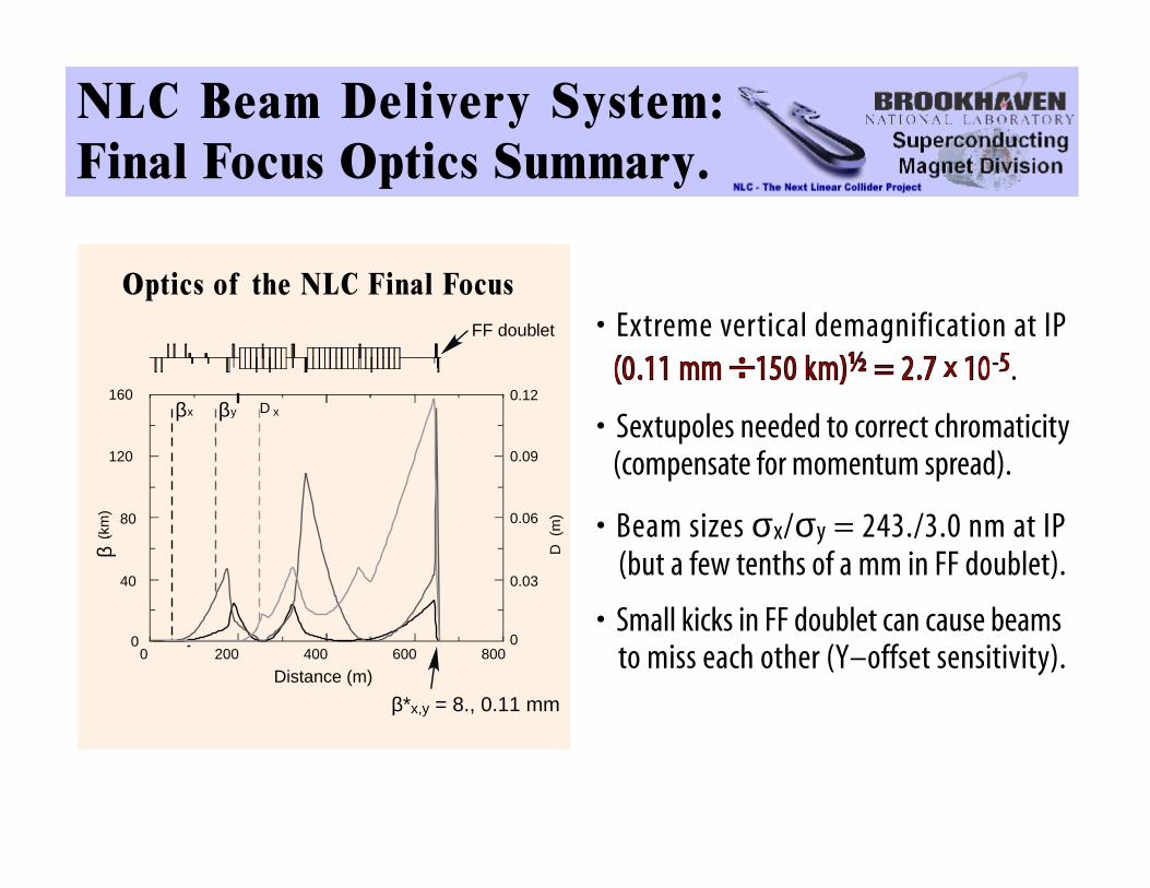
O ptics of the N L C F inal Focus
β*x,y = 8., 0.11 mm
• Extreme vertical demagnification at IP.
• Sextupoles needed to correct chromaticity(compensate for momentum spread).
• Beam sizes σx/σy = 243./3.0 nm at IP(but a few tenths of a mm in FF doublet).
• Small kicks in FF doublet can cause beamsto miss each other (Y–offset sensitivity).
FF doublet
β β

QD0
e+ ∆
yoff
P = 250 GeV/c
Bρ = 834 T·mG = 144 T/mσy = 0.11 mm
∆θy = 0.74 nr
σy = 3 nmL* = 3.8 m
Lm = 2 m
Let yoff = 1 nm, then ∆B = 1.44e-7 T
θ = 2 · 1.44e-7834
= 0.34e-9 radians
4.8 m
θ·L = 4.8 · 3.4e-10 = 1.6e-9 m
QD0
IP
QD0
QD0
QD0
N L C B eam D elivery S ystem :Q uadrupole O ffsetS ensitivity.

S eism ic Iso latio n Issu es(ground m otion).
Many groups are actively working in this area. Indepen-dent of the type of magnet used there will have to be somesystem that will perform active seismic isolation. It will beassumed that any superconducting magnet system will bemounted on an active isolation platform.
M o tio n c a u se d b y th ecryogenic system .
Various cryogenic system configurations will have to be investigated.These configurations will have to minimize any motion the cryogenicsystem might create in the cryostat and/or cold mass.
Different cooling schemes will have to be looked into to see which one willproduce the smallest vibration. Some choices could be forced flow, 4.2°Khelium, 1.8°K superfluid or conduction cooling for the magnet.
It will be important to develop a model of the mechanical system. Thismodel can be used to investigate what inf luence the connectioncomponents (bel lows, f lex hoses, straps, posts etc.) wil l have inenhancing or minimizing vibration of cold mass relative to the cryostat.
Also passive isolation techniques should be incorporated in any design.

A ctive vibration isolationof the cold m ass.
The choice of cooling scheme, mechanical design, and passive dampingwill be required to minimize vibration of the cold mass to a level that anactive system can reduce further to the nanometer level. Use of existingnanometer positioning sensors, piezoelectric actuators, and low noiseaccelerometers will need to be investigated for use in a cryogenic systemand in the presence of a moderate magnetic field.
These sensors and actuators are currently being used in active vibrationisolation systems. The technology used in these sensors and actuatorsshould allow them to perform in this environment but an active isolationsystem for the cold mass will require six degrees of freedom.
This will mean that many sensors and actuators will be needed and aDSP based control system will be needed for feedback, feed-forward, andsensor processing.