Session: 2 0.1 IT 601: Mobile Computing Session 2 Wireless Transmission Basics Prof. Anirudha Sahoo...
72
Session: 2 0.1 IT 601: Mobile Computing Session 2 Wireless Transmission Basics Prof. Anirudha Sahoo IIT Bombay
-
Upload
julia-lewis -
Category
Documents
-
view
222 -
download
1
Transcript of Session: 2 0.1 IT 601: Mobile Computing Session 2 Wireless Transmission Basics Prof. Anirudha Sahoo...

Session: 2 0.1
IT 601: Mobile Computing
Session 2Wireless Transmission Basics
Prof. Anirudha SahooIIT Bombay

Session: 2 0.2
Spectrum and bandwidth
• Electromagnetic signals are made up of many frequencies
• Shown in the next example
)])3(2(sin3/1)2[sin()/4()( tfftts

Session: 2 0.3
Source: StallingsFIG 1

Session: 2 0.4
Spectrum and bandwidth
• The 2nd frequency is an integer multiple of the first frequency– When all of the frequency components of a signal
are integer multiples of one frequency, the latter frequency is called fundamental frequency (f)
– period of the resultant signal is equal to the period of the fundamental frequency
• Period of s(t) is T=1/f

Session: 2 0.5
Fourier Analysis
• Any signal is made up of components at various frequencies, in which each component is a sinusoid.– Adding enough sinusoidal signals with appropriate
amplitude, frequency and phase, any electromagnetic signal can be constructed

Session: 2 0.6
Spectrum and bandwidth
• It is the range of frequencies that a signal contains (among its components)– In the example, spectrum is from f to 3f– absolute bandwidth is the width of the spectrum
• 3f-f = 2f

Session: 2 0.7
Data Rate and bandwidth
• There is a direct relationship between data rate (or signal carrying capacity) and bandwidth
• Suppose we let a positive pulse represent 1 and negative pulse represent 0– Then the waveform (next slide) represents 1010..
– Duration of each pulse is tbit = (1/2) (1/f)
– Thus data rate is 1/ tbit = 2f bits/sec
• As we add more and more frequencies the wave looks more like a square wave

Session: 2 0.8
Source: Stallings
FIG 2

Session: 2 0.9
Example
• Looking at FIG 2(a) the bandwidth = 5f-f = 4f– If f=1MHz = 106 cycles/sec, then bandwidth = 4MHz– The period of the fundamental frequency = T = 1/f =
1 μs– So each bit takes up 0.5 μs i.e. data rate is 1/0.5
Mbps = 2 Mbps
Session: 2 0.10
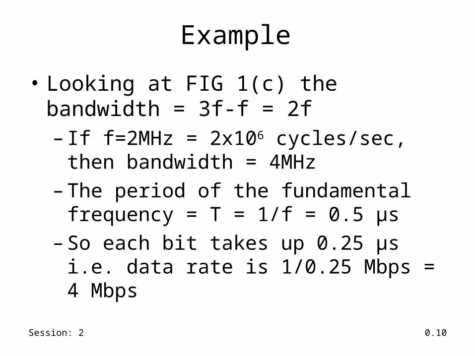
Example
• Looking at FIG 1(c) the bandwidth = 3f-f = 2f– If f=2MHz = 2x10⁶ cycles/sec, then bandwidth =
4MHz– The period of the fundamental frequency = T = 1/f =
0.5 μs– So each bit takes up 0.25 μs i.e. data rate is 1/0.25
Mbps = 4 Mbps

Session: 2 0.11
Example
• Thus a given bandwidth can support different data rate, depending on the ability of the receiver to discern the difference between 0 and 1 in the presence of noise and interference

Session: 2 0.12
Gain and Loss• Ratio between power levels of two signals is referred to as
Gain– gain (dB) = 10 log10 (Pout/Pin)
– loss (dB) = -10 log10 (Pout/Pin) = 10 log10 (Pin/Pout)
– Pout is output power level and Pin is input power level
• Signal of power 10mw transmitted over wireless channel, and receiver receives the signal with 2mw power:– gain (db) = 10 log10 (2/10) = -10 (0.698) = -6.98 dB– loss (db) = 6.98 dB

Session: 2 0.13
dBW power• dB-Watt
– power in dB transmitted with respect to a base power of 1 Watt• dBW = 10 log10 P
– P is power transmitted in Watt
– if power transmitted is 1 Watt• dBW = 10 log10 1 = 0 dBW
– 1000 watt transmission is 30 dBW

Session: 2 0.14
dBm power• dB-milliwatt
– better metric in wireless network– power in dB transmitted with respect to a base power of 1
milliwatt• dBm = 10 log10 P
– P is power transmitted in milliwatt
– if power transmitted is 1 milliwatt• dBm = 10 log10 1 = 0 dBm
– 10 milliwatt transmission is 10 dBm– 802.11b can transmit at a maximum power of 100mw = 20
dBm

Session: 2 0.15
Channel Capacity
Four concepts :• Data Rate : rate (in bps) at which data can be
communicated• Bandwidth: bandwidth of the transmitted signal as
constrained by the transmitter and the medium, expressed in Hz
• Noise : interfering electromagnetic signal that tend to reduce the integrity of data signal
• Error rate : rate at which receiver receives bits in error i.e. it receives a 0 when actually a 1 was sent and vice-versa

Session: 2 0.16
Nyquist Bandwidth
• Given a bandwidth of B, the highest signal rate that can be carried is 2B (when signal transmitted is binary (two voltage levels))– When M voltage levels are used, then each signal
level can represent log2M bits. Hence the Nyquist bandwidth (capacity) is given by
C = 2 B log2M

Session: 2 0.17
Shannon’s Capacity Formula
• When there is noise in the medium, capacity is given by– C <= B log2 (1 + SNR)
• SNR = signal power/noise power
– SNRdB = 10 log10 SNR

Session: 2 0.18
Bandwidth Allocation
• Necessary to avoid interference between different radio devices– Microwave woven should not interfere with TV transmission– Generally a radio transmitter is limited to a certain bandwidth
• 802.11channel has 30MHz bandwidth
– Power and placement of transmitter are regulated by authority
• Consumer devices are generally limited to less than 1W power

Session: 2 0.19
ISM and UNII Band
• Industrial, Scientific and Medical (ISM) band– 902-928 MHz in the USA– 433 and 868 MHz in Europe– 2400 MHz – 2483.5 MHz (license-free almost everywhere)– Peak power 1W (30dBm)
• but most devices operate at 100mW or less
– 802.11 uses the ISM band of 2.4GHz• Unlicensed National Information Infrastructure (UNII) bands
– 5.725 – 5.875 GHz

Session: 2 0.20
Antenna
• An electrical conductor or system of conductors used for radiating electromagnetic energy into space or for collecting electromagnetic energy from the space– An integral part of a wireless system

Session: 2 0.21
Radiation Patterns
• Antenna radiates power in all directions– but typically does not radiate equally in all directions
• Ideal antenna is one that radiates equal power in all direction– called an isotropic antenna– all points with equal power are located on a sphere
with the antenna as its center

Session: 2 0.22
Omnidirectional Antenna
• Produces omnidirectionalradiation pattern ofequal strength in alldirections
• Vector A and B are of equal length
Omnidirectional Antenna
Antenna location
A
B

Session: 2 0.23
Directional Antenna
• Radiates most power in oneaxis (direction)– radiates less in other direction– vector B is longer than vector A : more power radiated along B than A– directional along X
AB
X

Session: 2 0.24
Dipole Antenna
• Half-wave dipole or Hertz antenna consists of two straight collinear conductor of equal length• Length of the antenna is half the wavelength of the signal.
λ/2
Half-wave dipole

Session: 2 0.25
Quarter-wave antenna
• Quarter-wave or marconi antenna has a veritcal conductor of length quarter of the wavelength of the signal λ/4

Session: 2 0.26
Sectorized Antenna
• Several directional antenna combined on a single pole to provide sectorized antenna• each sector serves receivers listening it its direction
3 sector antenna

Session: 2 0.27
Antenna Gain
• A measure of the directionality of an antenna• Defined as the power output, in a particular
direction, compared to that produced in any direction by a perfect isotropic antenna – Example: if an antenna has a gain of 3dB, the
antenna is better (in that direction) than isotropic antenna by a factor of 2
Session: 2 0.28
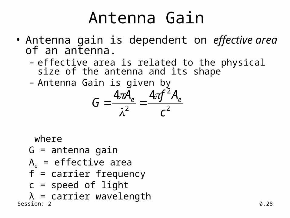
Antenna Gain• Antenna gain is dependent on effective area of an
antenna.– effective area is related to the physical size of the antenna and
its shape– Antenna Gain is given by
whereG = antenna gainAe = effective area f = carrier frequencyc = speed of lightλ = carrier wavelength
2
2
2
44
c
AfAG ee

Session: 2 0.29
Signal Propagation• Transmission range: receiver receives signal with an
error rate low enough to be able to communicate
• Detection range: transmitted power is high enough to detect the transmitter, but high error rate forbids communication
• Interference range: sender interferes with other transmissions by adding to the noise
transmission
sender
detection
interference

Session: 2 0.30
Signal Propagation
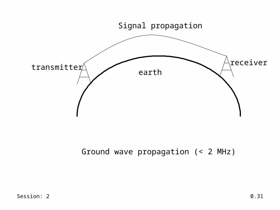
• Radio waves exhibit three fundamental propagation behavior– Ground wave (< 2 MHz) : waves with low frequency follow
earth’s surface• can propagate long distances
• Used for submarine communication or AM radio
– Sky wave (2-30 MHz) : waves reflect at the ionosphere and bounce back and forth between ionosphere and earth , travelling around the world
• Used by international broadcast and amateur radio
Session: 2 0.31
Signal propagation
transmitterreceiver
earth
Ground wave propagation (< 2 MHz)

Session: 2 0.32
transmitterreceiver
earth
sky wave propagation (2 - 30MHz)
ionosphere
Signal propagation

Session: 2 0.33
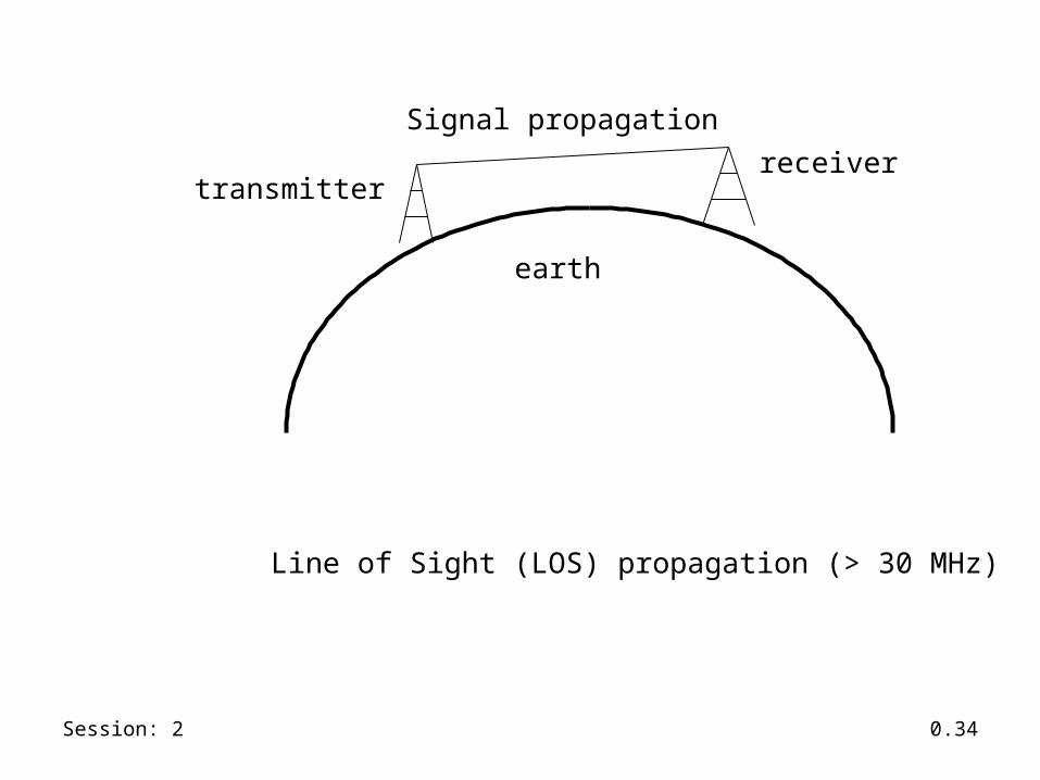
Signal Propagation
– Line of Sight (> 30 MHz) : emitted waves follow a straight line of sight• allows straight communication with satellites
or microwave links on the ground• used by mobile phone system, satellite
systems
Session: 2 0.34
Signal propagation
transmitterreceiver
earth
Line of Sight (LOS) propagation (> 30 MHz)
Session: 2 0.35
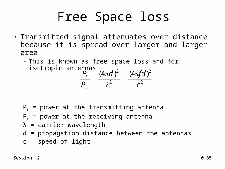
Free Space loss
• Transmitted signal attenuates over distance because it is spread over larger and larger area– This is known as free space loss and for isotropic antennas
Pt = power at the transmitting antenna
Pr = power at the receiving antennaλ = carrier wavelengthd = propagation distance between the antennasc = speed of light
2
2
2
2 )4()4(
c
fdd
P
P
r
t

Session: 2 0.36
Free Space loss
– For other antennas
Gt = Gain of transmitting antenna
Gr = Gain of receiving antenna
At = effective area of transmitting antenna
Ar = effective area of receiving antenna
trtrr
t
AA
d
GG
d
P
P 2
2
2 )()4(
Session: 2 0.37
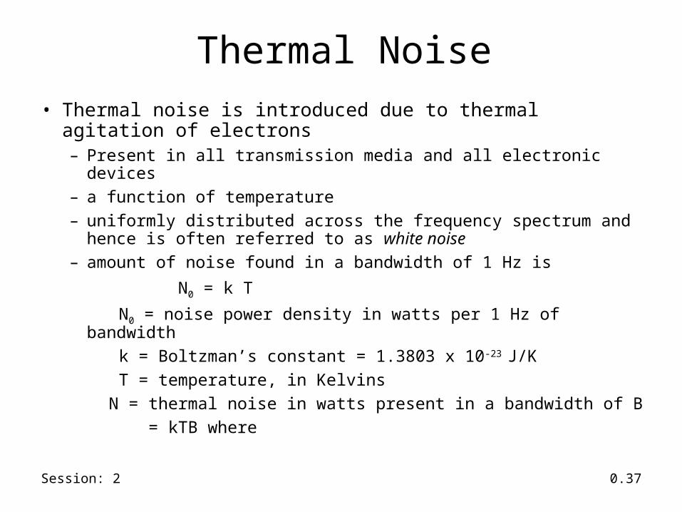
Thermal Noise• Thermal noise is introduced due to thermal agitation of electrons
– Present in all transmission media and all electronic devices– a function of temperature– uniformly distributed across the frequency spectrum and hence is often
referred to as white noise– amount of noise found in a bandwidth of 1 Hz is
N0 = k T
N0 = noise power density in watts per 1 Hz of bandwidth k = Boltzman’s constant = 1.3803 x 10⁻²³ J/K T = temperature, in Kelvins N = thermal noise in watts present in a bandwidth of B = kTB where

Session: 2 0.38
Data rate and error rate
• A parameter related to SNR that is more convenient for determining digital data rates and error rates– ratio of signal energy per bit to noise power density per
Hertz, Eb/N0
– R = bit rate of transmission, S= power of the signal,
Tb = time required to send 1 bit. Then R = 1/Tb
Eb = S Tb
so
kTR
S
N
RS
N
Eb 00
/

Session: 2 0.39
Data rate and error rate• Bit error rate is a decreasing function of Eb/N0
– If bit rate R is to increase, then to keep bit error rate (or Eb/N0) same, the transmitted signal power must increase, relative to noise
• Eb/N0 is related to SNR as follows
B = signal bandwidth(since N = N0 B)
R
B
N
S
N
Eb 0
Session: 2 0.40
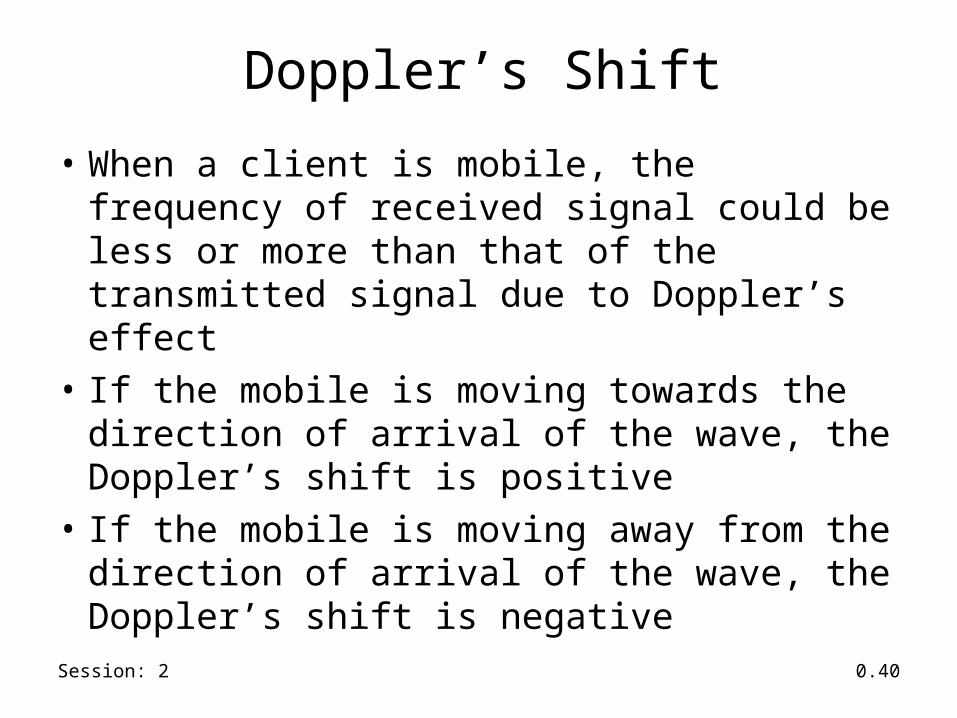
Doppler’s Shift
• When a client is mobile, the frequency of received signal could be less or more than that of the transmitted signal due to Doppler’s effect
• If the mobile is moving towards the direction of arrival of the wave, the Doppler’s shift is positive
• If the mobile is moving away from the direction of arrival of the wave, the Doppler’s shift is negative

Session: 2 0.41
Doppler’s Shift
wherefd =change in frequency
due to Doppler’s shiftv = constant velocity of the mobile receiverλ = wavelength of the transmission
θ
S
XY
cosv
fd

Session: 2 0.42
Doppler’s shift
f = fc + fd
where f = the received carrier frequencyfc = carrier frequency being transmitted
fd = Doppler’s shift as per the formula in the prev slide

Session: 2 0.43
Multipath Propagation
• Wireless signal can arrive at the receiver through different pahs– LOS– Reflections from objects– Diffraction
• Occurs at the edge of an impenetrable body that is large compared to the wavelength of the signal

Session: 2 0.44
Multipath Propagation (source: Stallings)
Session: 2 0.45
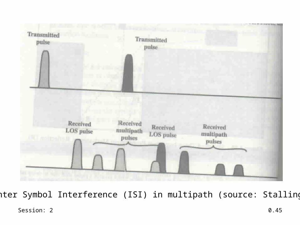
Inter Symbol Interference (ISI) in multipath (source: Stallings)

Session: 2 0.46
Effect of Multipath Propagation
• Multiple copies of the signal may arrive with different phases. If the phases add destructively, the signal level reduces relative to noise.
• Inter Symbol Interference (ISI)
Session: 2 0.47
Multiplexing
• A fundamental mechanism in communication system and networks
• Enables multiple users to share a medium• For wireless communication, multiplexing can be
carried out in four dimensions: space, time, frequency and code

Session: 2 0.48
Space division multiplexing
• Channels are assigned on the basis of “space” (but operate on same frequency)
• The assignment makes sure that the transmission do not interfere with each (with a guard band in between)

Session: 2 0.49
Space division multiplexing
Source: Schiller

Session: 2 0.50
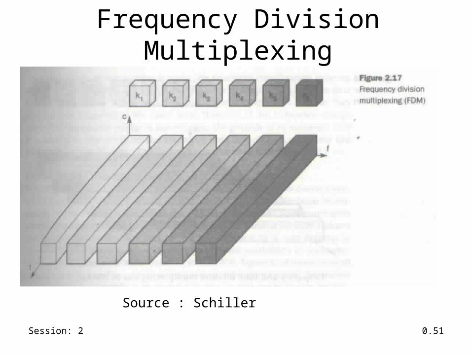
Frequency Division Multiplexing
• Frequency domain is subdivided into several non-overlapping frequency bands
• Each channel is assigned its own frequency band (with guard spaces in between)
Session: 2 0.51
Frequency Division Multiplexing
Source : Schiller

Session: 2 0.52
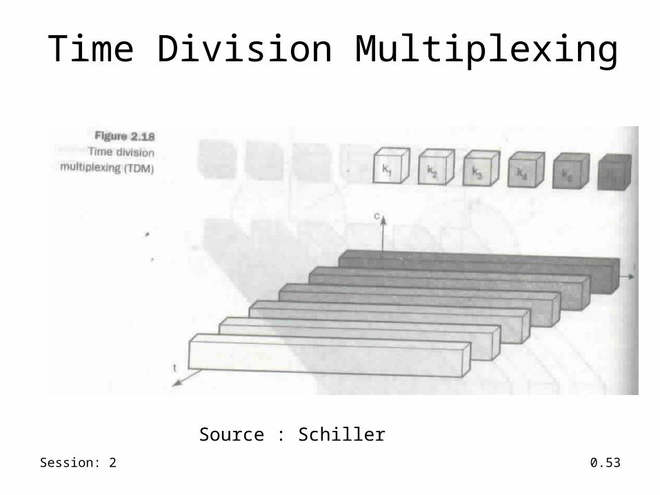
Time Division Multiplexing
• A channel is given the whole bandwidth for a certain amount of time– All senders use the same frequency, but at different
point of time
Session: 2 0.53
Time Division Multiplexing
Source : Schiller

Session: 2 0.54
Frequency and time division multiplexing
• A channel use a certain frequency for a certain amount of time and then uses a different frequency at some other time– Used in GSM systems

Session: 2 0.55
Frequency and time division multiplexing
Source : Schiller
Session: 2 0.56
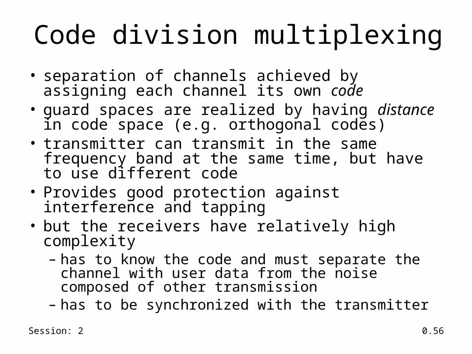
Code division multiplexing• separation of channels achieved by assigning each channel
its own code• guard spaces are realized by having distance in code space
(e.g. orthogonal codes)• transmitter can transmit in the same frequency band at the
same time, but have to use different code• Provides good protection against interference and tapping• but the receivers have relatively high complexity
– has to know the code and must separate the channel with user data from the noise composed of other transmission
– has to be synchronized with the transmitter
Session: 2 0.57
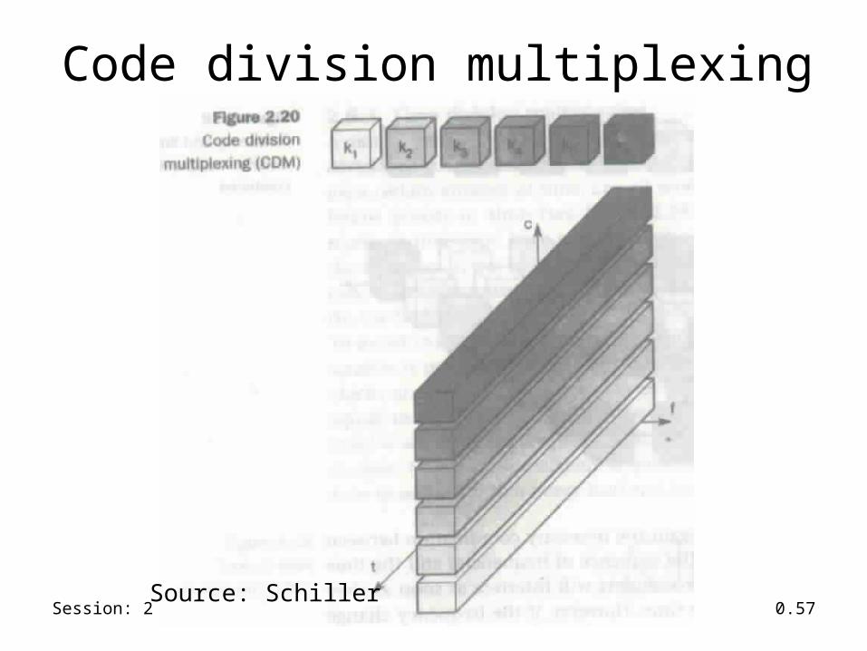
Code division multiplexing
Source: Schiller

Session: 2 0.58
Modulation
• Process of combining input signal and a carrier frequency at the transmitter
• Digital to analog modulation– necessary if the medium only carries analog signal
• Analog to analog modulation– needed to have effective transmission (otherwise the
antenna needed to transmit original signal could be large)
– permits frequency division multiplexing

Session: 2 0.59
Amplitude Shift Keying (ASK)
• ASK is the most simple digital modulation scheme• Two binary values, 0 and 1, are represented by two
different amplitude• In wireless, a constant amplitude cannot be
guaranteed, so ASK is typically not used

Session: 2 0.60
Amplitude Shift Keying (ASK)
1 0 1

Session: 2 0.61
Frequency Shift Keying (FSK)
• The simplest form of FSK is binary FSK– assigns one frequency f1 to binary 1 and another
frequency f2 binary 0
• Simple way to implement is to switch between two oscillators one with f1 and the other with f2
• The receiver can demodulate by having two bandpass filter

Session: 2 0.62
Frequency Shift Keying (FSK)
1 0 1
Session: 2 0.63
Phase Shift Keying (PSK)
• Uses shifts in the phase of a signal to represent data
• Shifting the phase by 1800 each time data changes: called binary PSK
• The receiver must synchronize in frequency and phase with the transmitter

Session: 2 0.64
Phase Shift Keying (PSK)
1 0 1

Session: 2 0.65
Quadrature Phase Shift Keying (Q-PSK)• Higher bit rate can be achieved
for the same bandwidth by coding two bits into one phase shift.
• 450 for data 11• 1350 for data 10• 2250 for data 00• 3150 for data 01 00 01
1110

Session: 2 0.66
Spread Spectrum
• Spreading the bandwidth needed to transmit data– Spread signal has the same energy as the original
signal, but is spread over a larger frequency range– provides resistance to narrowband interference

Session: 2 0.67
Spread Spectrum
user signal
broadband interferencenarrowband interference
dP/df dP/df dP/df
dP/df dP/df
f f f
f f
sender
receiver
user signalspreading with interference
despread apply bandpass filter
Session: 2 0.68
Direct Sequence Spread Spectrum• Takes a user bit sequence and performs an XOR with, what
is known as, chipping sequence• Each user bit duration tb
• chipping sequence has smaller pulses tc
• If chipping sequence is generated properly it may appear as random noise– sometimes called pseudo-noise (PN)
• tb/tc is known as the spreading factor– determines the bandwidth of the resultant signal
• Used by 802.11b

Session: 2 0.69
Direct Sequence Spread Spectrum
0 1
0 1 1 0 1 0 0 1 0 1 0 1
0 1 1 0 1 0 1 0 1 0 1 0
user data
chipping sequence
spread signal
XOR
tb
tc

Session: 2 0.70
Frequency Hopping Spread Spectrum
• Total available bandwidth is split into many channels of smaller bandwidth and guard spaces
• Transmitter and receiver stay on one of these channels for a certain time and then hop to another channel
• Implements FDM and TDM• Pattern of channel usage : hopping sequence• Time spent on a particular channel: dwell time

Session: 2 0.71
Frequency Hopping Spread Spectrum• Slow hopping
– Transmitter uses one frequency for several bit period– systems are cheaper, but are prone to narrow band interference
• Fast hopping– Transmitter changes frequency several times in one bit period– Transmitter and receivers have to stay synchronized within smaller
tolerances – Better immuned to narrow band interference as they stick to one frequency
for a very short period• Receiver must know the hopping sequence and stay synchronized
with the transmitter• Used by bluetooth

Session: 2 0.72
Frequency hopping spread spectrum
0 1 0 1 1
f1
f2
f3
f2
f3
f1
td
td
tb
t
t
t
user data
slow hopping 3bits/hop
fast hopping 3hops/bit
td = dwel time