Sesh Commuri School of Electrical and Computer Engineering University of Oklahoma, Norman Research...
68
Sesh Commuri School of Electrical and Computer Engineering University of Oklahoma, Norman Research in Intelligent Systems -Wireless Sensor Networks -Reconfigurable Computing -Applications December 08, 2006 SWAN 2006 University of Texas, Arlington, TX
-
Upload
megan-bell -
Category
Documents
-
view
215 -
download
2
Transcript of Sesh Commuri School of Electrical and Computer Engineering University of Oklahoma, Norman Research...

Sesh CommuriSchool of Electrical and Computer Engineering
University of Oklahoma, Norman
Research in Intelligent Systems-Wireless Sensor Networks-Reconfigurable Computing
-Applications
December 08, 2006
SWAN 2006University of Texas, Arlington, TX

Coverage Issues in WSNs
• Optimum Coverage in 2D and 3D spaces
• Border Coverage and Detection of Holes
• Self Healing Networks
• Tracking using Sensor Networks

What is a Wireless Sensor Network?
A Wireless Sensor Network (WSN) is an ad-hoc network composed of densely-populated tiny electronic sensing devices, distributed over an area or volume. The basic function of the network is to observe some phenomenon by using the sensors in the tiny devices and communicate it to a central point called the sink.
Introduction
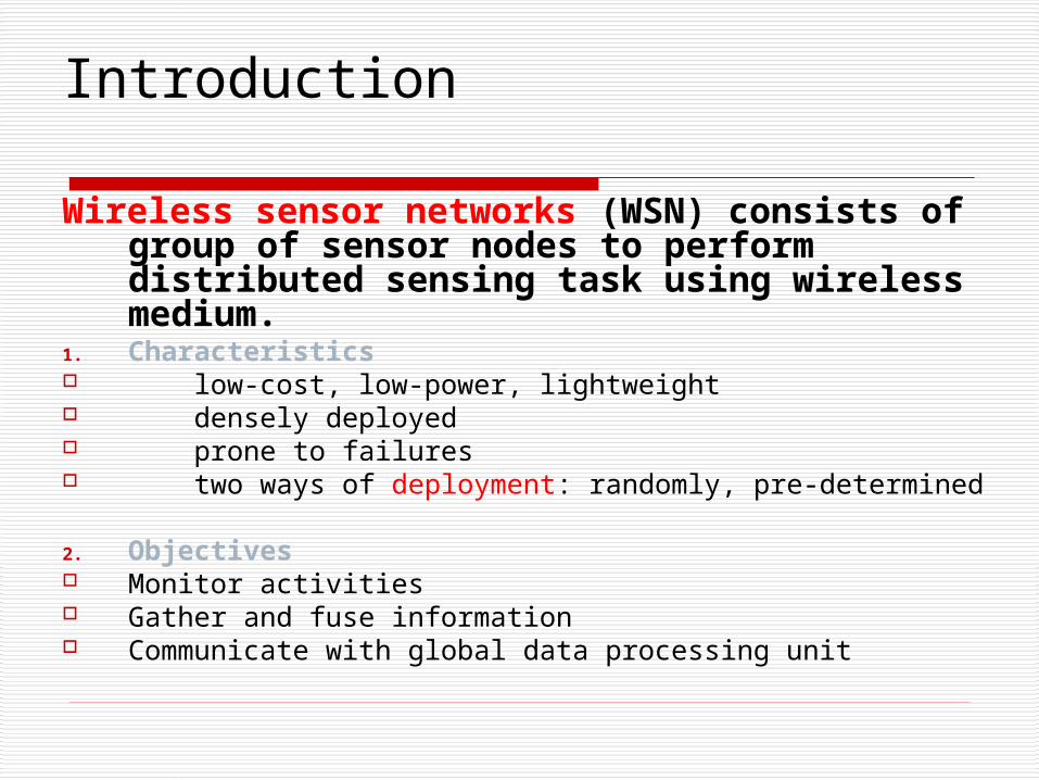
Wireless sensor networks (WSN) consists of group of sensor nodes to perform distributed sensing task using wireless medium.
1. Characteristics low-cost, low-power, lightweight densely deployed prone to failures two ways of deployment: randomly, pre-determined
2. Objectives Monitor activities Gather and fuse information Communicate with global data processing unit

Maximal Breach Path , Distance to
the closest sensor is
maximized (Worst Case)
Maximal Support Path , Distance to
the closest sensor is minimized
(Best Case)
The longer the exposure time , the greater the
sensing ability is.
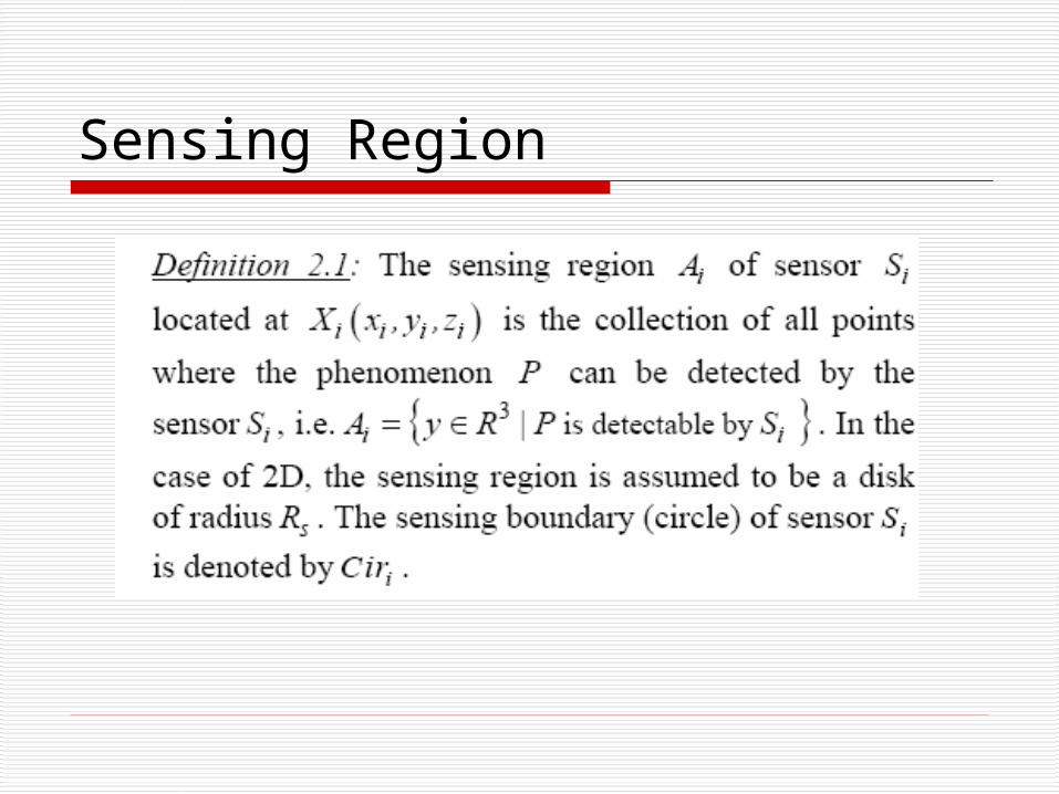
Sensing Region

Coverage The sensing region of C= {S1,…Sn} can
be expressed as :
A set of sensors is said to cover the region Ri if and only if
1
n
isi
C A
1 2, ,... }i a a amC S S S
i iR C
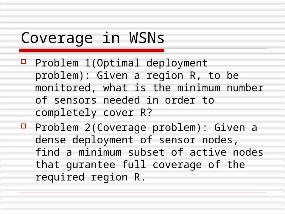
Coverage in WSNs Problem 1(Optimal deployment problem):
Given a region R, to be monitored, what is the minimum number of sensors needed in order to completely cover R?
Problem 2(Coverage problem): Given a dense deployment of sensor nodes, find a minimum subset of active nodes that gurantee full coverage of the required region R.

Optimal Coverage Theorem: Let D be the deployment of the sensor nodes
at the vertices ‘L’ of a body centered cubic (bcc) lattice spanning a region. Let be the distance between adjacent vertices of L and be the sensing radius of each sensor node. Then the deployment D is optimal if the lattice spacing .
Definition 5.3: The measure of optimality of a WSN is the ratio of the number of active nodes in the network to the minimum number of nodes that can completely
cover the same region.
1.118sR

Determination of Redundancy in Coverage
Consider a sensor node S0. The neighbor set of S0,N(S0)={S1,S2,..Sn}. Let Ck=A0∩Ak .
S0 is completely covered by its neighbors iff all Cks are covered by its neighboring sensing regions.
A circle C0 is completely covered by spheres if all the intersection points Ci∩CJ in D0 are covered by one or more adjacent spheres
0 100 200 300 400 500 600 700 800 900 10000
10
20
30
40
50
60
70
80
90
100
Grid Points
Num
ber
Of
Sen
sors
Cov
erin
g E
ach
Grid
Poi
ntBefore Running the Coverage Algorithm
After Running the Coverage Algorithm
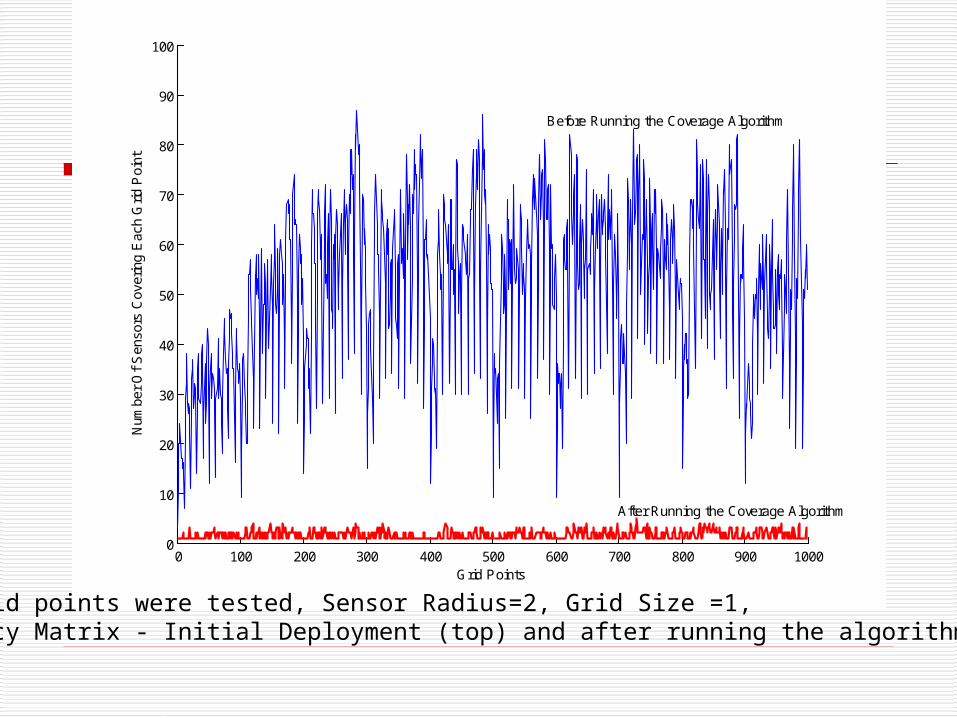
1000 Grid points were tested, Sensor Radius=2, Grid Size =1, Occupancy Matrix - Initial Deployment (top) and after running the algorithm (bottom).

Minimum and maximum thickness before and after running the algorithm
Min. Thickness Max. Thickness
Before 8 89
After 1 5

The effect of number of queries on the coverage lifetime of a self healing WSN with 800 nodes –(i) Initial deployment (Original); (ii) Reduced deployment (Algorithm).

The effect of number of queries on the coverage lifetime of a self healing WSN with 1600 nodes –(i) Initial deployment (Original); (ii) Reduced deployment (Algorithm).

Coverage Hole Problem
Given a dense deployment of sensor nodes in a region R, find the subset of active nodes that lie on the boundary of the coverage holes.

Key Idea
If the circumference of the sensor’s circle is completely covered by its neighbors then it is not a border sensor and therefore could be deactivated without affecting the overall border coverage.
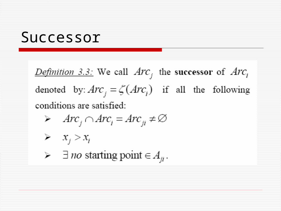
Successor
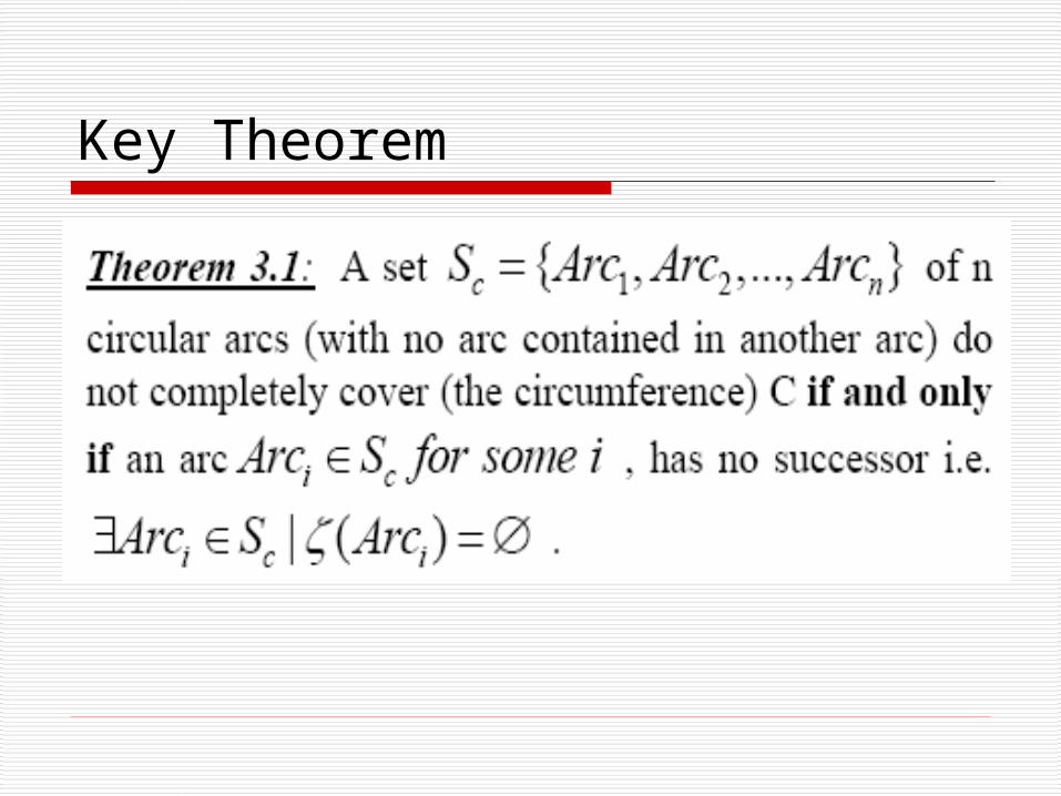
Key Theorem

Border Coverage

250 sensor nodes with sensing radius 0.75 units are randomly deployed in a 10x10 region.

31 sensor nodes are on the boundary cover of the 6 bounded coverage hole.
Optimal Sensor Placement for Border Perambulation
Sensor Network issues are addressed from the standpoint of optimal deployment of sensors nodes for boundary coverage. Lower bounds on the number of sensors needed for surveillance and target intrusion detection is presented and a “Border Perambulation” technique where each border node can swap between working and sleeping modes and the network only maintains a subset of working nodes

Optimal 2D Deployment

System Lifetime
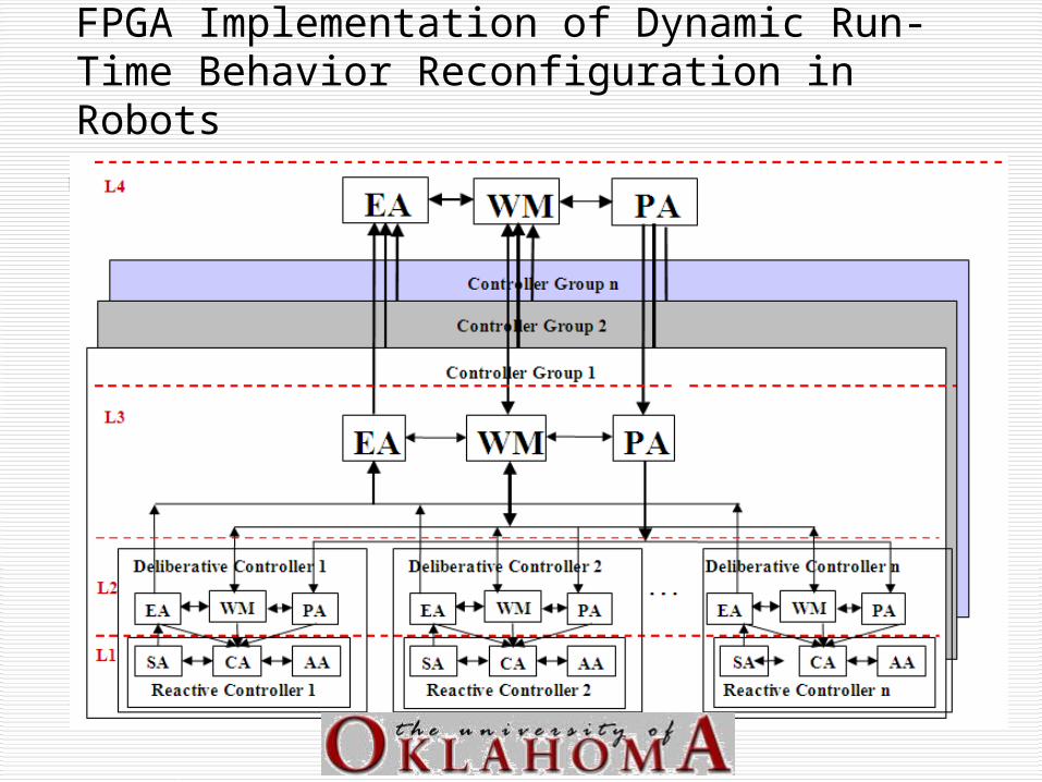
FPGA Implementation of Dynamic Run-Time Behavior Reconfiguration in Robots

FPGA Implementation of Dynamic Run-Time Behavior Reconfiguration in Robots
GoalDesign an appropriate architecture and implementation methodology for the implementation of Intelligent Robots.
- The architecture must allow for the integration of the various
functional modules and subsystems into the overall system.
- The methodology must address issues such as the network
connectivity, latency, bandwidth, reliability, and inter-module
communications that affect the system performance.

FPGA Implementation of Dynamic Run-Time Behavior Reconfiguration in Robots
The architecture must address issues such as:
the ability to dynamically configure and retask individual robots,
the ability of the robots to identify and accommodate system faults,
distributed /centralized control of the robot teams, information and resource sharing between multiple
robots, and the efficiency of fault tolerance and learning algorithms.
FPGA Implementation of Dynamic Run-Time Behavior Reconfiguration in Robots
Hardware Reconfiguration
What is Reconfiguration ? Ability of a system to change its execution path as
commanded by an application
Types of Reconfiguration Static Reconfiguration Dynamic Reconfiguration
Advantage FPGA’s can be reconfigured any number of times to
implement a hardware circuit

Static Reconfiguration
To upgrade/install new configuration for a system System has to be taken offline Reload with new set of data Reboot
Negative Impacts System Downtime

Dynamic Reconfiguration
Changes or modifications can be made while the system is under operation
System down time is avoided Flexibility to upgrade standards/features
Types of Dynamic Reconfiguration Full Reconfiguration Partial Reconfiguration

Full Reconfiguration
System starts with a Built In Self Test
Checks the proper functionality of the connected components
Reconfigures itself and resumes normal operations

Partial Reconfiguration
System modifications can be done on the fly
Reconfigures a portion of the system leaving the operational units untouched
Adds flexibility to the system

Use Case View of System Functionality

Logical Diagram of Layer 2 Entities and
Interfaces to Layer 1

Logical Diagram of Layer 2 Entities and
Interfaces to Layer 1
d d ix u y u cos ; sin ;

Controller for Wall Following
090 ( ) ( )2
f rh s h f r d
d du K K d d K d

Controller for Leader Follower
212 1
12 1 2 112
1( ')
dd
b b
kd k
N
k k x xd

Internal Architecture of Xilinx FPGA

Architecture of Prototype Test Bed

Creation of Interface Circuits for Sensors

Wall Following Using IR Sensors

Wall Following Using IR Sensors

Implementation of Reconfigurable Controllers on FPGAs
Module Occupied Slices (total : 4928) Equivalent Gate Count
Slice Count Percentage
Static Modules only 2862 58.1% 1,967,380
Static Modules + Wall Following Behavior Module
2983 60.5% 2,061,154
Static Modules + Wall Following + Leader/Follower
Behavior Modules
3273 66.5% 2,192,918
Static Modules + Wall Following +Leader/Follower + Obstacle Avoidance Behavior Modules
3463 70.3% 2,380,516
Overall Design without using partial reconfigurable
FPGAs
3509 71.2% 2,412,137

Implementation of Reconfigurable Controllers on FPGAs
Module Occupied Slices (total : 4928) Equivalent Gate Count
Slice Count Percentage
Static Modules only 2862 58.1% 1,967,380
Static Modules + Wall Following Behavior Module
3001 61% 2,062,930
Static Modules + Wall Following+Leader/Follower
Behavior Modules
3162 64.1% 2,170,551
Static Modules + Wall Following +Leader/Follower + Obstacle Avoidance Behavior Modules
3188 64.7% 2,190,868
Overall Design using partially reconfigurable FPGAs
3205 65.04% 2,202,382

Dynamic Reconfiguration based Fault Accommodation

MAGNETs: Mobile Adhoc Grid Networks
MAGNETs are a set of mobile computing devices that form a MANET which can be used for coordinated computation and communication.
Motivation and Objectives: A distributed set of mobile devices could be
observing a phenomenon and/or computing and communicating.
A user A would use these devices to perform analysis X, and a user B would use the same of subset of these devices to perform analysis Y.
Need for a adaptively reconfigurable architecture with protocols for to allow multi user application execution using a set of mobile communication and computational devices.
Develop a framework to manage resources in MAGNET.
Develop a high-level language specification using which a user can configure and use MAGNETs.

Layered MAGNET Architecture
Layered architectures allow of adaptively configuring and reconfiguring MAGNETs that suit the application needs.
Fabric Layer: data collection, storage, network resources, resident code for processing data, and computational resources
Connectively Layer: connection management functions, reliable transport of data, code fragments, and output resulting from distributed execution, authentication services for establishing user-based trust relationships.
Resource Layer: access to the resources at a node in the grid, API Interfaces, mobile code management
CollectiveGrid Resource Manager
ApplicationRoute Guidance and Planning
ResourceNode Resource Manager
ConnectivityLocal Communication Protocols
FabricNode Resources
Layered
MA
GN
ET
Arch
itecture
• Collective Layer: manages resources of the entire MAGNET.
• Application Layer: Execution of Mobile code on the behalf of the user.

Augmentation of WSNs using Mobile Reconfigurable Cluster Heads (RCHs)

Augmentation of WSNs using Mobile Reconfigurable Cluster Heads (RCHs)
Query based reconfiguration in the RCH

Augmentation of WSNs using Mobile Reconfigurable Cluster Heads (RCHs)
0
2
4
6
8
10
12
0 10 20 30 40 50 60
Number of Sensor Nodes in the Network
Pro
ce
ss
ing
Tim
e (
mic
ro s
ec
on
ds
)
Using SCH
Using RCH with DPR
Number of Sensor Nodes in the network (Vs) Query processing time (in a network that supports 5 data aggregation operations)
0
20
40
60
80
100
120
140
160
180
200
0 10 20 30 40 50 60Number of Sensor Nodes in the Network
Po
wer
Co
nsu
mp
tio
n (
mW
)
Using SCH
Using RCH with DPR
Number of Sensor Nodes in the network (Vs) power consumption (in a network that supports 5 data aggregation operations)

Conclusions
• The case studies demonstrate the performance enhancement using hardware / software reconfiguration. • The methodology that is proposed enables the designer to accurately capture the system requirements (using Use Cases), model the system, simulate the system to understand the interactions between the different objects, and then dynamically generate the code. • The design methodology enables the implementation of high risk/ changing modules in the FPGA while high performance / static modules can be implemented in custom circuitry or ASICs. • Finally, it is shown through the case studies that the requirements for intelligent robots can be met in an efficient manner using hardware / software reconfiguration. It is shown that systems can be designed to function under centralized control or for autonomous behaviors.

Advances in
Intelligent Compaction of AC Pavements Sesh Commuri
Associate ProfessorSchool of Elec. & Computer
Engineering
Musharraf ZamanAssociate Dean for Research
College of Engineering

What is Intelligent Compaction (IC)?
Intelligent Compaction (IC) is the process of continuously controlling the operational parameters of a vibratory compactor to optimize compaction and meet required conditions.
The IC controls the different compaction parameters for the roller such as the frequency and amplitude of the vibrations of the drum, and the roller speed.
Key components of IC are a system to measure the stiffness of asphalt, sensors to monitor the location (GPS) and the operational parameters of the roller, and devices to record and display these data to the user.

Advantages of Intelligent Compaction
• Higher efficiency and increased productivity
(More than 30% reduction in labor and fuel costs
Reduction in the number of conventional spot tests
Example: 75% reduction in QA testing (Sweden))
• Higher adaptability (thin/thick lifts, soft/stiff subgrades)
• Better quality resulting from uniform and optimum compaction
• Less crushing of the aggregates
• Complete coverage of compaction surface evaluation
• Dynamic measurement of soil stiffness
• Increased life of the equipment.
Disadvantages:
• It requires sophisticated equipment to survive in rugged, off-road conditions
• It requires operator training
• IC rollers are more expensive than conventional compactors.
From J.L. Briaud, J. Seo, Intelligent Compaction: Overview and Research Needs, December 2003.
http://www.webs1.uidaho.edu/bayomy/trb/afh60/IntCompaction_Briaud_September2004_.pdf

Spectral Analysis of Vibrations During Compaction
(a) Loose Mix Specimen (b) Pre-Compacted Specimen

Vibration Signature with Compaction Pressure of 758.4 kPA (110 PSI)compaction time = 60 s; Mix Temp.=152 ; 6.5 kgs (14.33 lbs)0C
-PR7: 8.2% air void
-PR8: 8.7% air void

Effect of Compacted Density on Vibration Characteristics

Field Compaction Results – Effect of Subgrade / Pavement Design
(a) Interstate I-35 2-inch (S3 – PG 64-22) (b) 3-inch (S3 – PG 64-22) on 6 inch Concrete base
(c) 4-inch (S3 – PG 64-22) on compacted subgrade (d) 2-inch (S4 – PG 70-28 OK) on 8 inch S3

Construction Site
Will Rogers International AirportConstruction July 20-28, 2006

Will Rogers International AirportConstruction July 20-28, 2006
1500 feet
860 feet
790 feet
61
8 fe
et

Spectrogram of Vibrations and Predicted Density – Pass 2
Distance (feet)
Fre
qu
en
cy (
Hz)
NN
Pre
dic
ted
Co
mp
act
ion
Le
vel

Spectrogram of Vibrations and Predicted Density - Pass 3
Distance (feet)
Fre
qu
en
cy (
Hz)
NN
Pre
dic
ted
Co
mp
act
ion
Le
vel

W
idth
(fe
et)
De
nsi
ty -
So
uth
La
ne
(% C
om
pa
ctio
n)
De
nsi
ty -
No
rth
La
ne
(% C
om
pa
ctio
n)
Loc. Core PQI Vicinity
1 93.2 93.3 92.7-93.7
2 93.5 93.2 92.6-93.2
3 92.5 92.8 92.1-92.8
4 92.1 93.1 92.4-93.6
As Built Density Map

As Built Density Map
feet ->
feet ->
feet ->
% D
ensi
ty%
Den
sity
IACA
Output
~ 90 %
~ 92 %
~ 94 %

Relief Features in Subgrade

NDP Control of Prosthetic Ankle

NDP Control of Prosthetic Ankle
Fully locked out
Slow walking
Fast walking
Jogging
Heel Strike
Mid Swing
Toe Off
Heel Off
Mid Stance
Foot Flat
Heel Strike
0
Damper resistance during each stage of gait for a variety of activities.