SES PNNI Controller Overview - cisco.com · The SES PNNI Controller is a 7-slot chassis that...
26
CHAPTER 1-1 SES PNNI Controller Software Configuration Guide Release 1.0, Part Number 78-6123-03, May 2000 1 SES PNNI Controller Overview The Cisco SES PNNI Controller is a Service Expansion Shelf (SES) controller that attaches to a BPX 8600 series switch to provide Private Network-to-Network Interface (PNNI) signaling and routing for the establishment of ATM switched virtual circuits (SVCs) and Soft Permanent Virtual Circuits (SPVCs) over a BPX 8600 wide area network. Every BPX 8600 series switch that deploys PNNI signaling and routing is collocated and attached to a SES PNNI Controller. The SES PNNI Controller uses Cisco’s Virtual Switch Interface (VSI) protocol to control the BPX switch for its networking application. SES PNNI Node Components The complete SES node architecture consists of the combined BPX 8620 switch and the SES PNNI Controller, in addition to the combined network management system—Cisco WAN Manager and CiscoView—used to configure and monitor the SES PNNI node. A SES PNNI node is the combined SES PNNI Controller and a BPX 8620 switch (Figure 1-1). Figure 1-1 SES PNNI Node BPX 8620 SES PNNI Controller SES PNNI Node
Transcript of SES PNNI Controller Overview - cisco.com · The SES PNNI Controller is a 7-slot chassis that...

SES PNNI ContRelease 1.0, Part Number 78-6123-03, May 2000
C H A P T E R 1
SES PNNI Controller OverviewThe Cisco SES PNNI Controller is a Service Expansion Shelf (SES) controller that attaches to a BPX 8600 series switch to provide Private Network-to-Network Interface (PNNI) signaling and routing for the establishment of ATM switched virtual circuits (SVCs) and Soft Permanent Virtual Circuits (SPVCs) over a BPX 8600 wide area network. Every BPX 8600 series switch that deploys PNNI signaling and routing is collocated and attached to a SES PNNI Controller. The SES PNNI Controller uses Cisco’s Virtual Switch Interface (VSI) protocol to control the BPX switch for its networking application.
SES PNNI Node ComponentsThe complete SES node architecture consists of the combined BPX 8620 switch and the SES PNNI Controller, in addition to the combined network management system—Cisco WAN Manager and CiscoView—used to configure and monitor the SES PNNI node. A SES PNNI node is the combined SES PNNI Controller and a BPX 8620 switch (Figure 1-1).
Figure 1-1 SES PNNI Node
OC3
BPX 8620
SES PNNI Controller
SES PNNI Node
1-1roller Software Configuration Guide

Chapter 1 SES PNNI Controller OverviewSES PNNI Node Components
SES PNNI ControllerThe SES PNNI Controller is a 7-slot chassis that contains two Processor Switch Modules (PXMs) that run the PNNI and SVC software. One of the PXMs serves as the active processor, while the other serves as the standby. The PNNI controller is collocated with and cabled to the BPX switch with either the ATM/OC-3 interface (Figure 1-3) or the ATM/DS3 interfaces (Figure 1-4).
Note The Service Expansion Shelf (SES) can be used in several WAN switching applications, and is not limited to function only as a SES PNNI Controller. However, when used as the SES PNNI Controller, the SES may only be populated with two switch processor modules (PXMs) and associated backcards. The remaining five slots of a shelf in service as a SES PNNI Controller are not used.
Processor Switch Module (PXM1)
Two PXM1 cards must reside in the SES PNNI Controller to enable redundant PNNI functionality. Line and service cards are not applicable to PNNI operations and cannot be installed in the PNNI Controller.
Note The PXM used in the SES PNNI Controller application is logically identical to the PXM used in the MGX 8850 but is keyed to fit only in the PNNI Controller. Also, the PXM for the PNNI controller is referenced by a different model number than is the PXM used in an MGX 8850.
PXM1 Front Cards
The active PXM card controls the Service Expansion Shelf and runs the PNNI and SVC software, which controls the associated BPX switch for PNNI networking and ATM switched virtual circuits. The standby PXM provides backup redundancy if the active PXM fails.
PXM1 Back Cards
A pair of PXM1 back cards are required for each installed PXM1 front card. A PXM1 back card pair consists of the following:
• User interface backcard—PXM-UI
The PXM-UI backcard provides the following ports:
– Ethernet port
– RS232 Maintenance port
– RS232 Control port
– T1/E1 timing reference ports
– Audio and visual alarm interface port
• ATM trunk interface—PXM ATM uplink
The PXM ATM uplink backcard is the ATM Trunk Interface that provides line drivers for the uplink interface. For SES PNNI Controller applications, the PXM ATM interface uplink card uses either a single port from the quad OC-3 multi-mode port or the quad DS-3 port backcard.
1-2SES PNNI Controller Software Configuration Guide
Release 1.0, Part Number 78-6123-03, May 2000

Chapter 1 SES PNNI Controller OverviewSES PNNI Node Components
Figure 1-2 shows a diagram of the PXM1 backcard.
Figure 1-2 PXM1 Backcard Simple Block Diagram
A mismatch between the uplink back card type and that of the PXM1 will generate a major alarm. (The PXM has a daughter card that is factory installed and must match the type of ATM interface backcard.)
BPX 8620The BPX 8620 is a standards based, high-capacity broadband ATM switch that provides backbone ATM switching and delivers a wide range of other user services. For more information about the BPX, refer to the Cisco BPX 8600 Series Installation and Configuration documentation for release 9.2.
Broadband Switch Module
The Broadband Switch Module (BXM) is a multiplexing ATM interface card that uses STRATM-based application-specific integrated circuit (ASIC) technology to deliver ATM networking functions.
Interfaces Supported
The following interfaces for ATM CPE and ATM trunks are supported on the BXM for PNNI and ATM SVCs/SPVCs:
The SES PNNI node internal interface between the SES PNNI Controller and the BPX switch is either OC-3 or T3/E3.
PXM-UI
Terminal
NetworkManagement
PXM ATM Trunk Interface
OC-3 ATM Interface
Collocated BPX 8620 Switch
ProcessorMemoryHard diskPNNI and ATM Software
Ethernet
RS232
RS232Modem VSI software
T1/E1
-uplink backcard-Backcard
Control port
Maintenance port
Ext clocks
Alarm
LAN
timing referenceAlarmOutput
orDS3
Interface Card Type
OC-12 BXM-2-OC-12
OC-3 BXM-8-OC-3
T3 BXM-12-DS3
E3 BXM-12-E3
1-3SES PNNI Controller Software Configuration Guide
Release 1.0, Part Number 78-6123-03, May 2000

Chapter 1 SES PNNI Controller OverviewSES PNNI Node Components
UNI and NNI Interfaces
BXM trunks and ports are classified as User-to-Network Interface (UNI) or Network-to-Network Interface (NNI).
The UNI is the service interface for ATM customer premise equipment (CPE) connected to the SES PNNI node. It defines the signaling method which the CPE must use to request and setup SVCs/SPVCs through the wide-area ATM network. Used to send messages from the network to the CPE (such as a user device) on the status of the circuit and rate control information to prevent network congestion. Each UNI port in a SES PNNI node can support 16 ATM end systems addresses.
For ATM SVCs/SPVCs, the UNI supports either the ATM Forum 3.0 or 3.1 signaling standards as well as traditional ATM PVCs.
Note The BPX switch also supports high-speed ATM UNI ports.
The NNI is the interface to other SES PNNI nodes or foreign ATM switches. The WAN Service Node supports Interim Inter-switch Protocol (IISP) 3.0 /3.1 or the Private Network-to-Network Interface (PNNI). These NNI interfaces provide the switching and routing functions between Cisco WAN switching networks and other networks. Information passing across a NNI is related to circuit routing and status of the circuit in the adjacent network.
Note In this guide, a trunk refers to the connection between two BPX switches, but NNI may also refer to both a connection between WAN Service Nodes and a connection between a WAN Service Node and a foreign switch.
Broadband Controller Card
The Broadband Controller Card (BCC) is a microprocessor-based system controller used to control the overall operation of the BPX switch. The controller card is a front card that is usually equipped as a redundant pair. Slots number 7 and number 8 of the BPX chassis are reserved for the active and standby broadband controller cards. Each broadband controller front card requires a corresponding back card.
BPX BCC Major Functions
The BCC performs the following major system functions for the BPX switch portion of a SES PNNI node:
• Runs the system software for controlling, configuring, diagnosing, and monitoring the BPX switch.
• Contains the crosspoint switch matrix operating at 800 Mbps per serial link (BCC-32 or BCC-3) or up to 1600 Mbps (BCC-4).
• Contains the arbiter, which controls polling on each high-speed data port and grants the access to the switch matrix for each port with data to transfer.
• Generates Stratum 3 system clocking, which can be synchronized to either a selected trunk or an external clock input.
1-4SES PNNI Controller Software Configuration Guide
Release 1.0, Part Number 78-6123-03, May 2000

Chapter 1 SES PNNI Controller OverviewSES PNNI Node Components
• Communicates configuration and control information to all other cards in the same node over the backplane communication bus.
• Communicates with all other nodes in the network.
• Provides a communications processor for an Ethernet LAN port plus two low-speed data ports.
– The BCC-bc provides the physical interface for the BCC-32.
– The BCC-3-bc provides the physical interface for the BCC-3 and BCC-4.
SES/BPX InterfacesFigure 1-3 and Figure 1-4 are simple block diagrams of a SES PNNI node. These figures illustrate the internal interfaces of the SES PNNI node (that is, between the PBX SES PNNI controller and the BPX switch) and the external interfaces. The external interfaces of a SES PNNI node connect to ATM end systems, and ATM trunks to other ATM or PNNI nodes or networks, and connections to Network Management Systems, such as the Cisco WAN Manager or CiscoView.
1-5SES PNNI Controller Software Configuration Guide
Release 1.0, Part Number 78-6123-03, May 2000

Chapter 1 SES PNNI Controller OverviewSES PNNI Node Components
Figure 1-3 OC-3 Cabling from Two BXMs to Redundant PXMs
PXM(active)
PXM(standby)
BXMBXM
BXMBXM
BPX 8600
BCC
User Interface
To other BPX 8600 switchesor PNNI nodesATM trunksATM
End Systems
ATMEnd Systems
ATM trunksNNI
toForeign switch
Ethernet
SES PNNI NodeNetwork ManagementStation
BXMs
SES PNNI Controller
Cisco WAN Managerand
CiscoView
OC-3
TerminalRS232
1-6SES PNNI Controller Software Configuration Guide
Release 1.0, Part Number 78-6123-03, May 2000
Chapter 1 SES PNNI Controller OverviewSystem and Network Management
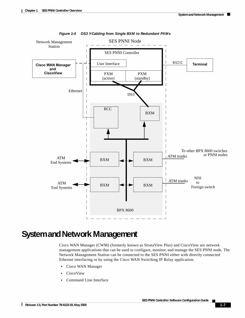
Figure 1-4 DS3 Y-Cabling from Single BXM to Redundant PXMs
System and Network ManagementCisco WAN Manager (CWM) (formerly known as StrataView Plus) and CiscoView are network management applications that can be used to configure, monitor, and manage the SES PNNI node. The Network Management Station can be connected to the SES PNNI either with directly connected Ethernet interfacing or by using the Cisco WAN Switching IP Relay application.
• Cisco WAN Manager
• CiscoView
• Command Line Interface
PXM(active)
PXM(standby)
DS3
BXMBXM
BXMBXM
BPX 8600
BCC
User Interface
ATM trunksATMEnd Systems
ATMEnd Systems
ATM trunksNNI
toForeign switch
Ethernet
SES PNNI NodeNetwork ManagementStation
BXM
To other BPX 8600 switchesor PNNI nodes
SES PNNI Controller
Cisco WAN Managerand
CiscoView
TerminalRS232
1-7SES PNNI Controller Software Configuration Guide
Release 1.0, Part Number 78-6123-03, May 2000
Chapter 1 SES PNNI Controller OverviewSystem and Network Management
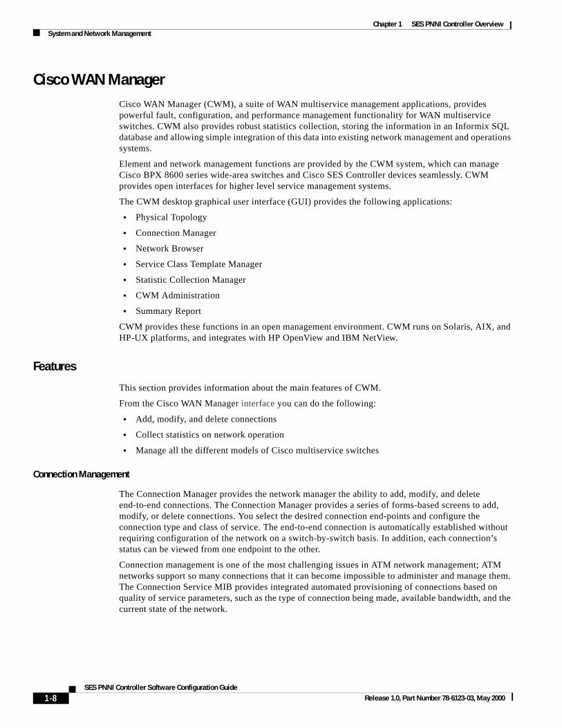
Cisco WAN ManagerCisco WAN Manager (CWM), a suite of WAN multiservice management applications, provides powerful fault, configuration, and performance management functionality for WAN multiservice switches. CWM also provides robust statistics collection, storing the information in an Informix SQL database and allowing simple integration of this data into existing network management and operations systems.
Element and network management functions are provided by the CWM system, which can manage Cisco BPX 8600 series wide-area switches and Cisco SES Controller devices seamlessly. CWM provides open interfaces for higher level service management systems.
The CWM desktop graphical user interface (GUI) provides the following applications:
• Physical Topology
• Connection Manager
• Network Browser
• Service Class Template Manager
• Statistic Collection Manager
• CWM Administration
• Summary Report
CWM provides these functions in an open management environment. CWM runs on Solaris, AIX, and HP-UX platforms, and integrates with HP OpenView and IBM NetView.
Features
This section provides information about the main features of CWM.
From the Cisco WAN Manager interface you can do the following:
• Add, modify, and delete connections
• Collect statistics on network operation
• Manage all the different models of Cisco multiservice switches
Connection Management
The Connection Manager provides the network manager the ability to add, modify, and delete end-to-end connections. The Connection Manager provides a series of forms-based screens to add, modify, or delete connections. You select the desired connection end-points and configure the connection type and class of service. The end-to-end connection is automatically established without requiring configuration of the network on a switch-by-switch basis. In addition, each connection’s status can be viewed from one endpoint to the other.
Connection management is one of the most challenging issues in ATM network management; ATM networks support so many connections that it can become impossible to administer and manage them. The Connection Service MIB provides integrated automated provisioning of connections based on quality of service parameters, such as the type of connection being made, available bandwidth, and the current state of the network.
1-8SES PNNI Controller Software Configuration Guide
Release 1.0, Part Number 78-6123-03, May 2000
Chapter 1 SES PNNI Controller OverviewSystem and Network Management
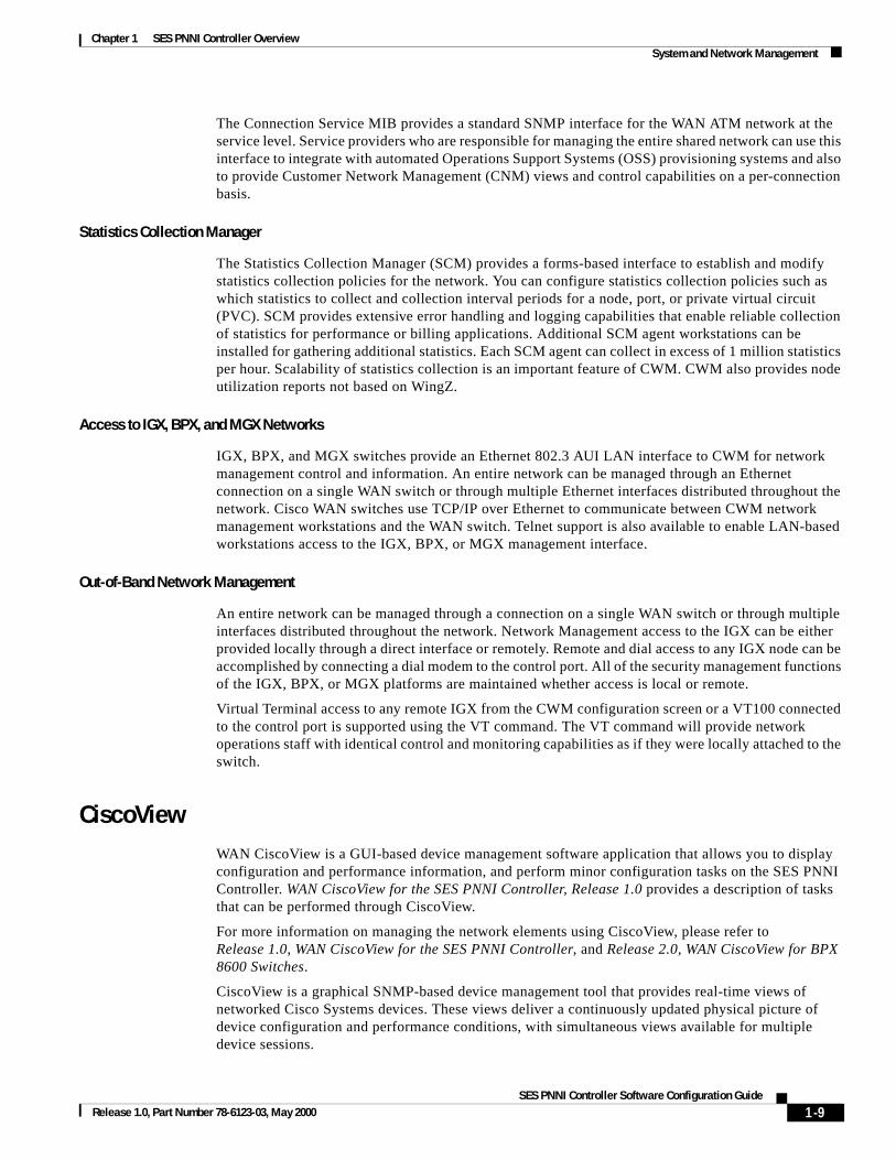
The Connection Service MIB provides a standard SNMP interface for the WAN ATM network at the service level. Service providers who are responsible for managing the entire shared network can use this interface to integrate with automated Operations Support Systems (OSS) provisioning systems and also to provide Customer Network Management (CNM) views and control capabilities on a per-connection basis.
Statistics Collection Manager
The Statistics Collection Manager (SCM) provides a forms-based interface to establish and modify statistics collection policies for the network. You can configure statistics collection policies such as which statistics to collect and collection interval periods for a node, port, or private virtual circuit (PVC). SCM provides extensive error handling and logging capabilities that enable reliable collection of statistics for performance or billing applications. Additional SCM agent workstations can be installed for gathering additional statistics. Each SCM agent can collect in excess of 1 million statistics per hour. Scalability of statistics collection is an important feature of CWM. CWM also provides node utilization reports not based on WingZ.
Access to IGX, BPX, and MGX Networks
IGX, BPX, and MGX switches provide an Ethernet 802.3 AUI LAN interface to CWM for network management control and information. An entire network can be managed through an Ethernet connection on a single WAN switch or through multiple Ethernet interfaces distributed throughout the network. Cisco WAN switches use TCP/IP over Ethernet to communicate between CWM network management workstations and the WAN switch. Telnet support is also available to enable LAN-based workstations access to the IGX, BPX, or MGX management interface.
Out-of-Band Network Management
An entire network can be managed through a connection on a single WAN switch or through multiple interfaces distributed throughout the network. Network Management access to the IGX can be either provided locally through a direct interface or remotely. Remote and dial access to any IGX node can be accomplished by connecting a dial modem to the control port. All of the security management functions of the IGX, BPX, or MGX platforms are maintained whether access is local or remote.
Virtual Terminal access to any remote IGX from the CWM configuration screen or a VT100 connected to the control port is supported using the VT command. The VT command will provide network operations staff with identical control and monitoring capabilities as if they were locally attached to the switch.
CiscoViewWAN CiscoView is a GUI-based device management software application that allows you to display configuration and performance information, and perform minor configuration tasks on the SES PNNI Controller. WAN CiscoView for the SES PNNI Controller, Release 1.0 provides a description of tasks that can be performed through CiscoView.
For more information on managing the network elements using CiscoView, please refer toRelease 1.0, WAN CiscoView for the SES PNNI Controller, and Release 2.0, WAN CiscoView for BPX 8600 Switches.
CiscoView is a graphical SNMP-based device management tool that provides real-time views of networked Cisco Systems devices. These views deliver a continuously updated physical picture of device configuration and performance conditions, with simultaneous views available for multiple device sessions.
1-9SES PNNI Controller Software Configuration Guide
Release 1.0, Part Number 78-6123-03, May 2000

Chapter 1 SES PNNI Controller OverviewPNNI Routing and ATM Switched Virtual Circuits
Features
This section provides information about the main features of CiscoView.
From the CiscoView interface you can do the following:
• View a graphical representation of the device, including component (interface, card, power supply) status.
• Configure parameters for devices, cards, and interfaces.
• Monitor real-time statistics for interfaces, resource utilization, and device performance.
• Telnet, access CCO, send E-mail to TAC, set values for SNMP parameters and community strings.
• Perform device-specific operations as defined in each device package.
• Manage groups of stackable devices.
CiscoView contains common devices functions such as selecting main menu options and categories of information for configuring and monitoring. Each device package also has its own specific menu options and functions.
Command Line InterfaceThe SES Controller command line interface (CLI) configures ATM SVCs, SPVCs, and PNNI routing and signaling on the SES Controller. These commands are described in depth inAppendix B, “SVC, SPVC and PNNI Commands.”
Note Throughout this manual, some BPX-specific commands are presented where applicable to PNNI configuration tasks. For additional information on the BPX command suite, refer to Cisco BPX 8600 Series Installation and Configuration document and the Cisco WAN Switching Command Reference and SuperUser Command Reference for Switch Software Release 9.2.
PNNI Routing and ATM Switched Virtual CircuitsThe SES PNNI node adds PNNI routing and ATM switched virtual circuits to a traditional Cisco WAN switching network. The network created with SES PNNI nodes is enhanced for SVCs/SPVCs and also supports traditional ATM and Frame Relay permanent virtual circuits (PVCs) in a separately partitioned AutoRoute network.
ATM SVCs are ATM connections that are established and maintained by a standardized signaling mechanism between ATM CPE (ATM end systems) across a Cisco WAN switching network. ATM SVCs are set up in accordance with user demand and removed when calls are completed, thus freeing up network resources. (See Chapter 3, “ATM Signaling and Switched Virtual Circuits,” for more information about ATM SVCs.)
SPVCs (Soft Permanent Virtual Circuit) are persistent ATM connections established by the PNNI routing database and signalling across a Cisco WAN switching network. (See Chapter 5, “ATM Soft Permanent Virtual Circuits,” for more information about ATM SPVCs.)
1-10SES PNNI Controller Software Configuration Guide
Release 1.0, Part Number 78-6123-03, May 2000

Chapter 1 SES PNNI Controller OverviewPNNI Routing and ATM Switched Virtual Circuits
The routing protocol that the SES PNNI node uses to establish connections is the Private Network-to-Network Interface (PNNI) routing protocol. Defined by the ATM Forum for ATM networks, PNNI is a dynamic routing protocol that responds to changes in network resource availability, and scales to large networks.
SES PNNI node resources, such as port virtual path identifier (VPI) range and bandwidth and trunk bandwidth, are partitioned between SVCs/SPVCs and PVCs. Resource partitioning provides a firewall between PVCs and SVCs/SVPs so that problems with CPE or large bursts do not affect the robustness and availability of PVC services. Bursty data for either PVCs or SVCs/SPVCs can always use any unused link bandwidth, regardless of partitioning.
ATM Routing and SignalingFor ATM SVCs/SPVCs, the SES PNNI node uses the Private Network-to-Network Interface (also known as Private Network to Node Interface). As defined by the ATM Forum, PNNI is a dynamic routing protocol specified for use between private ATM switches (for example, Cisco SES PNNI nodes), and between groups of private ATM switches. PNNI defines the following two protocol categories:
Topology State Routing
Topology state routine distributes topology information between switches and clusters of switches. This information is used to compute paths through the network. A key feature of the PNNI mechanism is its ability to automatically configure itself in networks in which the address structure reflects the topology. PNNI topology and routing are based on the well-known link-state routing technique. See Chapter 2, “ATM Routing,” for more information about PNNI routing protocol.
PNNI Signaling
PNNI Signaling defines the message flows used to establish point-to-point connections across the ATM network. This protocol is based on the ATM Forum UNI signaling and includes functions to support source routing, crankback, load balancing, and alternate routing of call setup requests in case of connection setup failure.Interim Inter-Switch Protocol Routing
Interim Inter-switch Protocol (IISP) is a static routing protocol defined by the ATM Forum to provide base level UNI signaling between switches until PNNI was specified. IISP is sometimes referred to as PNNI Version 0. The IISP provides users with a fundamental level of multi-vendor switch interoperability based on the existing ATM Forum UNI 3.1 specifications. IISP assumes no exchange of routing information between switching systems. It uses a a fixed routing algorithm with static routes. Routing is done on a hop-by-hop basis by making a best match of the destination address in the call setup with address entries in the next hop routing table at a given switching system. Entries in the next hop routing table are manually configured. See Chapter 2, “ATM Routing,” for more information about IISP.
ILMIThe SES PNNI node uses ILMI to automatically identify which of its interfaces are User-Network Interface (UNI), attached to ATM end systems, and which are Network-to-Network Interface (NNI), attached to other systems. This information is used by ATM Routing protocols, Private Network-to-Network Interface (PNNI), and Interim-Interswitch Signaling Protocol (IISP) to automatically discover and bring up a network of interconnected SES PNNI nodes.
1-11SES PNNI Controller Software Configuration Guide
Release 1.0, Part Number 78-6123-03, May 2000
Chapter 1 SES PNNI Controller OverviewRedundant SES PNNI Controllers
The ILMI protocol is also used for ATM address registration across an ATM UNI, and to:
• Configure ATM end systems with ATM address prefixes.
• Enable the SES PNNI node to discover the 48-bit Media Access Control (MAC) addresses of the attached systems.
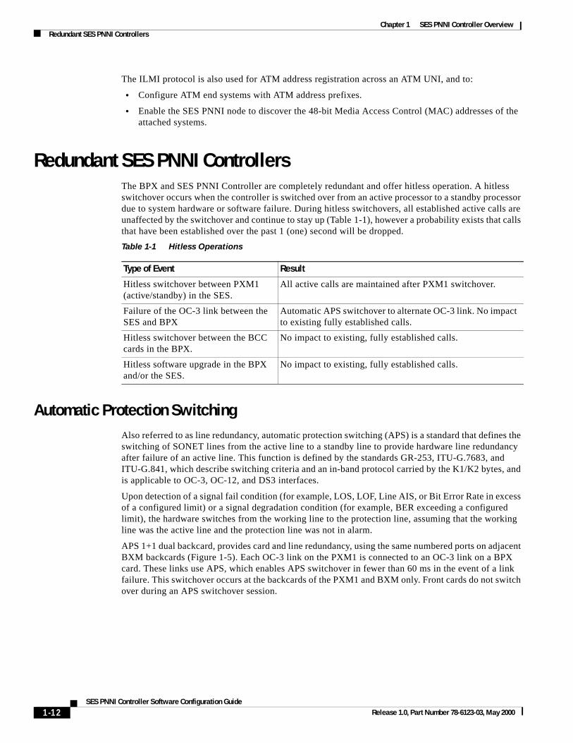
Redundant SES PNNI ControllersThe BPX and SES PNNI Controller are completely redundant and offer hitless operation. A hitless switchover occurs when the controller is switched over from an active processor to a standby processor due to system hardware or software failure. During hitless switchovers, all established active calls are unaffected by the switchover and continue to stay up (Table 1-1), however a probability exists that calls that have been established over the past 1 (one) second will be dropped.
Automatic Protection SwitchingAlso referred to as line redundancy, automatic protection switching (APS) is a standard that defines the switching of SONET lines from the active line to a standby line to provide hardware line redundancy after failure of an active line. This function is defined by the standards GR-253, ITU-G.7683, and ITU-G.841, which describe switching criteria and an in-band protocol carried by the K1/K2 bytes, and is applicable to OC-3, OC-12, and DS3 interfaces.
Upon detection of a signal fail condition (for example, LOS, LOF, Line AIS, or Bit Error Rate in excess of a configured limit) or a signal degradation condition (for example, BER exceeding a configured limit), the hardware switches from the working line to the protection line, assuming that the working line was the active line and the protection line was not in alarm.
APS 1+1 dual backcard, provides card and line redundancy, using the same numbered ports on adjacent BXM backcards (Figure 1-5). Each OC-3 link on the PXM1 is connected to an OC-3 link on a BPX card. These links use APS, which enables APS switchover in fewer than 60 ms in the event of a link failure. This switchover occurs at the backcards of the PXM1 and BXM only. Front cards do not switch over during an APS switchover session.
Table 1-1 Hitless Operations
Type of Event Result
Hitless switchover between PXM1 (active/standby) in the SES.
All active calls are maintained after PXM1 switchover.
Failure of the OC-3 link between the SES and BPX
Automatic APS switchover to alternate OC-3 link. No impact to existing fully established calls.
Hitless switchover between the BCC cards in the BPX.
No impact to existing, fully established calls.
Hitless software upgrade in the BPX and/or the SES.
No impact to existing, fully established calls.
1-12SES PNNI Controller Software Configuration Guide
Release 1.0, Part Number 78-6123-03, May 2000

Chapter 1 SES PNNI Controller OverviewSES PNNI Node Software Architecture
Figure 1-5 APS 1 + 1 (Card and Line Redundancy) Dual Backcard Configuration
Coordination between the interfaces on the two ends of the lines is provided using an in-band protocol.
Y-Cable RedundancyThe SES supports Y-cable port redundancy. To set up port redundancy, installing two identical front and back PXM card sets, connecting them with a Y-cable on each paired port.
During normal operation, the primary card set is “active” and carrying traffic, while the secondary card set is in “standby.” The primary set configuration is the configuration for both the primary and redundant set. If you reset the primary cards or the primary card set becomes inactive for another reason, the secondary card set becomes active.
SES PNNI Node Software ArchitectureThe SES PNNI Node Software is distributed across three branches of software:
• PXM Software
• BPX Software
• Network Management Software (namely, Cisco WAN Manager and CiscoView)
These three branches of software interact to create SES PNNI nodes, a PNNI network, and ATM SVC/SPVC services.
BPX
SES PNNI
PXMPXM
OC-3 (APS 1+1 dual backcard protected)
BXMBXM
Controller
1-13SES PNNI Controller Software Configuration Guide
Release 1.0, Part Number 78-6123-03, May 2000

Chapter 1 SES PNNI Controller OverviewSES PNNI Node Software Architecture
PXM SoftwareThe PXM software for the SES PNNI Controller contains three major functional blocks (Figure 1-6):
• Control Point Software
• PNNI and SVC Software
• Platform Software
VSI software provides the VSI master application used by the PNNI and SVC/SPVC networking control software to control the BPX switch. (See the section Virtual Switch Interface Protocol, page 1-17, for more information.)
Figure 1-6 PXM Software Architecture
Control Point Software
Control Point software runs on the PXM at the SES PNNI Controller to provide a single, integrated point of control for the PXM and the PNNI and ATM SVC application software. It provides the interface that enables configuration of the PNNI and ATM SVC parameters for the SES PNNI node, and the PXM management functions.
This interface takes the form of an API, in which requests to get or send data are made to PNNI and SVC software through a well defined message based interface. Additionally, PNNI and SVC software may generate events to the Control Point, for reasons such as alarm status changes (such as connection routing and rerouting).
The Control Point software enables direct access to the SES PNNI Controller command sets by providing a consistent, integrated SNMP proxy for the platform, and CLI for the service expansion shelf.
Control Point Software
Platform Software
PNNI and SVCSoftware
NodeManagement
Configurationand Monitoring
PlatformControl
ManagementAPIs
To NMS(CLI, SV+, CWM, CiscoView)
(runs on PXM)
(runs on PXM)
(runs on PXM)
1-14SES PNNI Controller Software Configuration Guide
Release 1.0, Part Number 78-6123-03, May 2000

Chapter 1 SES PNNI Controller OverviewSES PNNI Node Software Architecture
PNNI and SVC Software
The PNNI and SVC software architecture consists of three major components (Figure 1-7):
• Call Control Block
• PNNI
• Redundancy Manager
Figure 1-7 SES PNNI Software Architecture
Call Control Block
The major features implemented in Call Control Block are as follows:
• UNI 3.X SVC support.
• IISP 1.0 support plus crankback, load balancing, and overbooking enhancements.
• PNNI/IISP and AutoRoute coexistence on the same port, trunk, and BPX node in the network.
The PNNI controller will use the VSI partition to provide its networking capabilities.
• Set of MIBs to allow both provisioning and surveillance of the PNNI system.
The major components in Call Control block are shown in Table 1-2.
Call ControlRouteAgent
ATMSignalingStack
SSCOP
ConnectionManager
ResourceManager
PNNI
StandbySESPNNI Controller
VSI Master
SES OC-3 Driver
BPX Switch
RedundancyManager
Call Control
Active SES PNNI Controller
(RM)
1-15SES PNNI Controller Software Configuration Guide
Release 1.0, Part Number 78-6123-03, May 2000

Chapter 1 SES PNNI Controller OverviewSES PNNI Node Software Architecture
PNNI
Performs topology information exchange and routing information exchange with other SES PNNI Controllers.
PNNI pre-calculates a set of possible routing paths for all reachable nodes in the network. The routing information is saved in a routing table of the route agent.
Redundancy Manager
The redundancy manager supports active call redundancy by shadowing the essential data structure information on the standby SES PNNI Controller.
Table 1-2 Call Control Block Components
Components Description
Call Control • Sets up/tears down cross-connect on the switch when an SVC is established/released.
• Provides the finite state machine of point-to-point calls.
Note Point-to-multipoint calls will be supported in a future release.
• Performs address filtering.
• Works with the PNNI process for source routing or termination port determination.
• Releases calls upon switch port failure.
ATM Signaling Stack • Includes ATM Forum UNI 3.x, PNNI 1.0, and IISP Signaling.
• Provides the message encoding and decoding of the signaling.
• Manages the signaling stack finite state machine.
SSCOP • Layer 2 protocol that provides a reliable AAL layer link between a pair of signaling entities.
VSI Master • Interface between SES PNNI Controller and switch. The SES PNNI Controller uses this interface to set cross-connect on the switch and pass the ILMI address registration information from switch interface module to Call Control.
RM (Resource Manager) • Manages the interface resource such as VPI/VCI and bandwidth. It also performs UPC control and CAC operations.
CM (Connection Manager) • Manages the addition and deletion of cross-connects.
Route Agent • Contains the routing table that is updated by PNNI.
• Searches an optimal path in the routing table, as requested by Call Control.
• Performs on-demand route calculation if no path is found in the pre-calculated routing table.
1-16SES PNNI Controller Software Configuration Guide
Release 1.0, Part Number 78-6123-03, May 2000
Chapter 1 SES PNNI Controller OverviewVirtual Switch Interface Protocol
PNNI and SVC Routing Software
The major features included in PNNI Routing Block are as follows:
• PNNI 1.0 support
• PNNI Multiple Peer Group (MPG) support
• Special network-wide and local load balancing and enhanced crankback
• Overbooking
Platform Software
Platform software runs on the PXM at the SES PNNI Controller to provide low-level operation of the system (including resource management and physical redundancy control) and a set of services to the remaining subsystems. These services are categorized as Basic Platform-Specific Configuration and Monitoring Service, and Platform Infrastructure.
Platform-Specific Configuration and Monitoring Services
The platform software provides an API to the management layer (namely, the Control Point software) to allow the configuration and monitoring of cards, ports, redundancy options and any platform specific features. It also enables the platform software to generate asynchronous events to the management layer. This API consists of a message passing request/response protocol running on the PXM card.
Basic Platform Infrastructure
The platform software provides the basic infrastructure for the following:
• Drivers for the PXM segmentation and reassembly (SAR)
• Inter-card communications between PXM cards for redundancy control
• File system support
• PXM redundancy
Virtual Switch Interface ProtocolThe Virtual Switch Interface (VSI) protocol controls a Cisco Wide Area Network Switch, such as the BPX 8600, for networking applications, such as Multiprotocol Label Switching (MPLS) or PNNI routing. With VSI, external controllers are used to control the switch for applications not supported by the proprietary WAN switch set of routing protocols known as AutoRoute.
The SES PNNI Controller uses the Virtual Switch Interface (VSI) protocol to control BPX VC applications by creating a separate control plane, distinct from the standard BPX AutoRoute control plane, that includes all the SES PNNI nodes in the PNNI network. The SES PNNI node VSI control plane is the API that separates portable network software from platform-specific software and firmware.
This section describes VSI in the following topics:
• VSI Master and Slaves
• Resource Partitioning
• System Templates
For more information about the VSI protocol, see Appendix D, “Virtual Switch Interface.”
1-17SES PNNI Controller Software Configuration Guide
Release 1.0, Part Number 78-6123-03, May 2000

Chapter 1 SES PNNI Controller OverviewVirtual Switch Interface Protocol
VSI Master and SlavesThe VSI is a master/slave protocol. The master VSI protocol runs on the SES PNNI Controller, and is referred to in this application, as the VSI controller. The slave VSI protocol runs on the BXMs on the BPX 8620 (Figure 1-8).
Figure 1-8 Controller and Slave VSIs
The VSI controller automatically establishes a link between the VSI master and every VSI slave on the associated switch (Figure 1-9). When enabled, the VSI slaves establish links.
The SES controller uses VSI control channel to set up virtual circuit cross connect via VSI slaves on BXM cards.
Figure 1-9 VSI Master and VSI Slave Example
Resource PartitioningInternal resources on the BPX must be partitioned between AutoRoute and the external VSI controller to enable VSI establishment of a separate PNNI control plan. In a SES PNNI node, the resources are partitioned between AutoRoute and PNNI on the BXM cards (Figure 1-10). An MPLS partition can also be added, but theSES PNNI Controller will not control or share the MPLS partition. A separate MPLS controller will be required.
PNNI application(VSI controller)
VSI master
Auto
ResourceRoute
Management
VSIslaves BPX
SES PNNI Controller
Slave
Slave
Slave VSI Master
PNNI Application
BPX SES PNNI Controller
1-18SES PNNI Controller Software Configuration Guide
Release 1.0, Part Number 78-6123-03, May 2000

Chapter 1 SES PNNI Controller OverviewVirtual Switch Interface Protocol
Figure 1-10 BPX Resource Partitioning
BXM Resources
The resources that must be partitioned between AutoRoute and PNNI on each BXM (Figure 1-11) are:
• Logical Connection Numbers (LCNs)
• Virtual Path Identifiers (VPIs)
• Port Bandwidth
Figure 1-11 Resource Partitioning Between AutoRoute and VSI
BXM
BPX 8620
BCC
To other BPX 8620 switchesor PNNI nodes
ATM trunksATM
End Systems
ATMEnd Systems ATM trunks
NNIto
Foreign switch
PNNI AutoRoute
BXM
PNNI AutoRoute
BXM
PNNI AutoRoute
BXM
PNNI AutoRoute
BXM
PNNI AutoRoute
0
0
4095
4095
LCNs
VPIs
PortBandwidth
VSIStarting VPI
VSIStarting LCNAutoRoute LCNs
AutoRoute VPIs
AutoRoute BW
VSI LCNs
VSI VPIs
VSI BW = Line Rate - AutoRoute BW
1-19SES PNNI Controller Software Configuration Guide
Release 1.0, Part Number 78-6123-03, May 2000

Chapter 1 SES PNNI Controller OverviewVirtual Switch Interface Protocol
By default, all bandwidth is allocated to AutoRoute when a BXM trunk is added. To preserve resources for a VSI, the bandwidth allocation can be changed by using the cnfrsrc (configure resources) command on the BPX switch. See Chapter 10, “Configuring ATM SVCs, PNNI Routing, and SPVCs” for more information about resource partitioning.
Once the resources are partitioned, the PNNI controller (VSI controller) can use the resources configured for it to set up user ATM SVCs/SPVCs across the PNNI network.
To add or remove bandwidth from autoroute without affecting the dynamic aspect, increase the VSI partition and decrease autoroute.
System TemplatesThis section introduces the system templates.
• Service Class Templates (SCT)
• Qbin Templates
For more information about SCT and Qbin templates, see Chapter 5, “Configuring ATM SVCs and PNNI Routing.”
Note The terms—Class of Service Template and Service Class Template (SCT) —can be used interchangeably.
Service Class Templates
Each BPX switch (running Release 9.2 and up) contains a set of nine Service Class Templates (SCT) that can be downloaded to an interface service module—a BXM—as needed. These Service Class Templates have pre-defined, non-changeable values that are tailored for typical interfaces such as PNNI trunk or PNNI UNI.
SCT templates contain two classes of data:
• Per-VC Parameters
These parameters are necessary to establish a per-VC connection and includes entries such as UPC actions, various bandwidth-related items, per-VC thresholds and hardware-specific items.
• Class of Service Buffers (Qbins)
These parameters provide Quality of Service (QoS) support. Full QoS implies that each VC is served through one of a number of Class of Service buffers (Qbins) which are differentiated by their QoS characteristics.
The SES PNNI Controller (VSI master) can use the Service Class Templates to configure the appropriate type of ATM connection.
When an ATM SVC connection setup request is received from the VSI Master in the SES PNNI Controller, the VSI slave (as in the BXM) uses the SCT index of the request to retrieve the corresponding set of extended parameters defined in the template for the corresponding index. The slave uses these values to complete the connection setup and to program the hardware.
The general types of parameters passed from a VSI Master to a Slave include:
• Service type identifier
• QoS parameters (such as CLR, CTD, CDV)
1-20SES PNNI Controller Software Configuration Guide
Release 1.0, Part Number 78-6123-03, May 2000

Chapter 1 SES PNNI Controller OverviewAutoRoute and PNNI
• Bandwidth parameters (such as PCR, MCR)
• Other ATM Forum Traffic Management 4.0 parameters
Each VC added by a VSI master is assigned to a specific service class by means of a 32-bit service type identifier. Current identifiers are for the following:
• ATM Forum service types
• AutoRoute
• MPLS
When a connection setup request is received from a VSI master controller, the VSI slave uses the service type identifier to index into a Service Class Template database containing extended parameter settings for connections that match the index. The firmware then programs the hardware with the applicable extended parameter values to complete the connection setup.
Service Class Templates on the BPX are maintained by the BCC and are downloaded to the BXM cards as part of the card configuration process occurring as a result of card activation, rebuild, or switchover.
Note In Release 9.2 the templates are not configurable.
Qbin Templates
One of the parameters specified for each service type is the BXM class of service buffer (Qbin) to be used. The Qbin buffers provide separation of service type to match the QoS requirements. This mapping defines a relationship between the template and the Qbin interface configuration.
A Qbin template defines a default configuration for the set of Qbins for the logical interface. When a template assignment is made to an interface, the corresponding default Qbin configuration becomes the interface’s Qbin configuration. Some of the parameters of the interface’s Qbin configuration can be changed on a per interface basis. Such changes affect only that interface’s Qbin configuration and no others, and do not affect the Qbin templates.
Qbin templates only are used with Qbins that are available to VSI partitions, namely Qbins 10 through 15. Qbins 10 through 15 are used by the VSI (on interfaces configured as trunks or ports. Qbins 0 through 9 are reserved for and configured by AutoRoute.
AutoRoute and PNNIThis section introduces the major ATM SVC applications supported by the PNNI controller:
• SVC with PNNI Routing
• SVC with Mixed PNNI and IISP Networks
• SVP, SPVC, SPVP
• PNNI and AutoRoute co-existence on the Network
1-21SES PNNI Controller Software Configuration Guide
Release 1.0, Part Number 78-6123-03, May 2000

Chapter 1 SES PNNI Controller OverviewAutoRoute and PNNI
SVC with PNNI Routing
The SES PNNI node supports SVC applications with PNNI routing (Figure 1-12). PNNI routing protocol runs between ATM switches. The network topology information and routing information are exchanged between ATM switches via PNNI routing protocol. The routing path from a calling CPE to a called CPE is dynamically selected based on current network traffic and resource conditions.
Note A PNNI network uses AutoRoute functions for network timing.
Figure 1-12 PNNI Network
SVC with Mixed PNNI and IISP Networks
Where SVC applications contain both IISP and PNNI networking, IISP runs on the edges of a PNNI network and interconnects non-PNNI networks via a backbone PNNI network (Figure 1-13). IISP maintains a set of static routing tables to direct signaling between a non-PNNI network and a PNNI network. The static routing information can be advertised into PNNI network through boundary switches (namely, switches #4 and #6 in the illustration). With static route advertising, the end system A on the non-PNNI network #a can place a call to the end system C on the non-PNNI network #b. Because the PNNI network is running PNNI 1.0 Signaling, and IISP is based on UNI 3.1 Signaling, IE mapping between PNNI 1.0 and UNI 3.1 occurs on the boundary switches # 4 and #6.
ATMSwitch
ATMSwitch
ATMSwitch
ATMSwitch
ATMSwitch
A
C
BATMSwitch
PNNI
PNNI PNNI
PNNI
UNI
UNI
PNNI
PNNI
PNNI
PNNI
UNI
#1#2
#3
#4#5
#6
1-22SES PNNI Controller Software Configuration Guide
Release 1.0, Part Number 78-6123-03, May 2000

Chapter 1 SES PNNI Controller OverviewAutoRoute and PNNI
Figure 1-13 PNNI Network with IISP Trunks
PNNI and AutoRoute Co-existence on the Network
A SES PNNI network allows both PNNI and AutoRoute networks to coexist in the same physical network (Figure 1-14). The illustration shows switches #1 through #6 all participating in the PNNI network, while switches #4, #5, and #6 are part of AutoRoute network. The trunks between switch #4 and switch #5, and between switch #5 and switch #6, carry both AutoRoute and PNNI traffic on the same physical trunk. The trunk bandwidth is partitioned between AutoRoute and PNNI traffic at trunk initialization stage.
ATMSwitch
ATMSwitch
ATMSwitch
ATMSwitch
ATMSwitch
AC
BATMSwitch
PNNI
PNNI PNNI
UNI
PNNI
PNNI
PNNI
PNNI
#1#2
#3
#4#5
#6
PNNINetwork
IISP
PNNI
IISP
UNI
UNI
non-PNNINetwork
non-PNNINetwork
#a
#b
Boundary
Boundary
1-23SES PNNI Controller Software Configuration Guide
Release 1.0, Part Number 78-6123-03, May 2000

Chapter 1 SES PNNI Controller OverviewUser Interfaces and Network Management
Figure 1-14 Mixed AutoRoute and PNNI Networks
User Interfaces and Network ManagementThis section introduces the tools used at the PNNI Controller, the BPX 8600, CWM, and CiscoView to control and manage the SES PNNI node.
• Configuration and Network Management Tools
• Auto Configuration
Configuration and Network Management ToolsAll user interfaces access the SES PNNI Controller through control point software. The control point software then interacts with the PNNI, SVC, VSI, and platform software.
ATMSwitch
ATMSwitch
ATMSwitch
ATMSwitch
ATMSwitch
AC
BATMSwitch
PNNI
PNNI PNNI
UNI
PNNI
PNNI
AutoRoute
AutoRoute
#1#2
#3
#4#5
#6
PNNINetwork
PVC
PNNI
PVC
UNI
UNI
non-PNNINetwork
non-PNNINetwork
#a
#b
PNNI
PNNI
AutoRoute Network
1-24SES PNNI Controller Software Configuration Guide
Release 1.0, Part Number 78-6123-03, May 2000

Chapter 1 SES PNNI Controller OverviewUser Interfaces and Network Management
The four main interfaces used to configure and operate a SES PNNI node are as follows:
1. SES Command Line Interface
The SES CLI can be used for low-level configuration and access to the SES PNNI Controller.
2. BPX Command Line Interface
A SES PNNI node consists of a SES PNNI Controller and a BPX switch. The BPX switch is configured and operated with the standard BPX switched software commands described in the Cisco WAN Switching Command Reference.
3. Cisco WAN Manager
The Cisco WAN Manager provides network management functions for a SES PNNI network. These functions are described in Chapter 11, “Network Management”. These features include the following:
– Topology—The physical topology of the nodes in the network will be provided. The SES will appear as a shelf under the BPX. CWM can only show physical topology.
– Traps display—All traps will be displayed in the form consistent with all other BPX/MGX 8850 traps and using the existing applications on the CWM.
– Network Browser—The Network Browser will be enhanced to indicate which trunks are PNNI trunks and will display additional state information related to PNNI on these trunks.
– Config/Restore—The configuration can be saved and restored using the standard CWM application.
– Image Download—The software images are downloaded to SES using the standard CWM download mechanism.
Note IP connectivity to the SES PNNI Controller is provided by using the inband IP Relay capability of AutoRoute. Therefore, AutoRoute will still be required in the network. Its main function will be for the use of IP Relay, Time of Day propagation, and Network Clock Sync. (Out-of-band network management connectivity is also provided through the Serial and Ethernet interfaces on the PXM.). These services will be provided in a pure PNNI network (namely, one that does not use AutoRoute) in a future release.
• CiscoView
CiscoView can be used to configure some aspects of a SES PNNI Controller, PNNI routing, and ATM SVCs/SPVCs. The CiscoView functions that are specific to the SES PNNI Controller are described in Chapter 11, “Network Management”.
Provisioning Data Saving
Configuration data is written to the disk and the DRAM, when configuration is changed. This data is used to initialize the PXM1 upon reset. The configuration data can be saved on external server such as CWM via configuration upload. The Configuration data can also be saved in a separate file and restored later if necessary.
System Error Log
The SES PNNI Controller maintains a log of system errors in BRAM, containing crucial system details prior to a system reset.
1-25SES PNNI Controller Software Configuration Guide
Release 1.0, Part Number 78-6123-03, May 2000

Chapter 1 SES PNNI Controller OverviewUser Interfaces and Network Management
Real Time Cell Statistics and Call Statistics
CWM provides remote access to cell statistics from physical interfaces and call statistics from SES PNNI Controller.
Event Log
The SES PNNI Controller maintains log files on system disk to log events in the system.
SNMP
The SES PNNI Controller complies with SNMP VI. The Management Information Base (MIBs) used by the SES PNNI Controller are described in Appendix E, “SNMP Management Information Base.”
SNMP Error Log
The SNMP Error log provides SNMP error details to the Cisco WAN Manager. CWM maintains a sequential log ordered list of Error Events for each SNMP Manager.
Trap/Alarm Log
Alarms generated by theSES PNNI Controller are mapped into traps and sent to the CWM. The SES provides support for Robust Trap Messages. Trap messages are maintained in a circular buffer, with the latest message overwriting the oldest. Each trap is labelled with a sequence numbers. By using these sequence numbers, management stations can request previously issued traps that were not received.
Auto ConfigurationThe SES PNNI nodes are preconfigured with Cisco ATM address prefixes, which are combined with the preconfigured MAC address of the switch to form a unique node identifier. These are used to configure both attached ATM end systems and to automatically bring up the PNNI routing hierarchy for simple network configurations
1-26SES PNNI Controller Software Configuration Guide
Release 1.0, Part Number 78-6123-03, May 2000