ServoClass Couplings - Zero-Max, Inc. · ServoClass couplings are made from a high strength...
12
ServoClass ® Couplings
Transcript of ServoClass Couplings - Zero-Max, Inc. · ServoClass couplings are made from a high strength...

ServoClass® Couplings

ZERO-MAX® ServoClass® Couplings
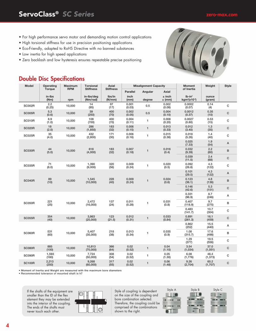
• For high performance servo motor and demanding motion control applications
• High torsional stiffness for use in precision positioning applications
• Eco-Friendly, adapted to RoHS Directive with no banned substances
• Low inertia for high speed reversing applications
• Zero backlash and low hysteresis ensures repeatable precise positioning
• Low bearing loads
• Available in 14 sizes in single and double disc models
• Double disc models provide highest misalignment capability
• Operating temperature range is -22° to +212°F (-30° to +100°C)
• Torque ratings range from 0.25 to 250Nm
• Hubs and center members manufactured of aluminum alloy for strength, durability, and both are treated to prevent oxidation and to preserve appearance
• Disc members are made of 304 stainless steel
• Couplings are precisely assembled using high strength, corrosion resistant fasteners
• Integral clamp style hubs provide fast, easy mounting
• RoHS compliant – manufactured of RoHS compliant materials and contains no banned substances
Aluminum Alloy Construction
304 Stainless steel disc packs
All fasteners are corrosion resistant
All models have clamp hubs
2
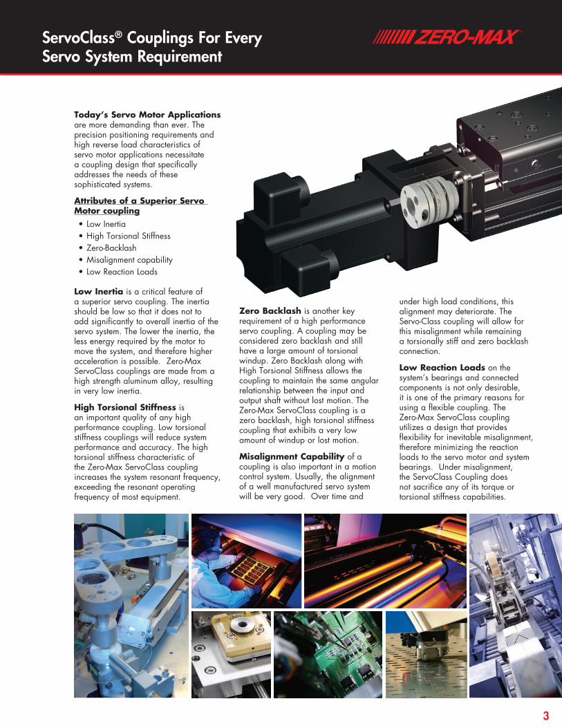
ServoClass® Couplings For Every Servo System Requirement
Today’s Servo Motor Applications are more demanding than ever. The precision positioning requirements and high reverse load characteristics of servo motor applications necessitate a coupling design that specifically addresses the needs of these sophisticated systems.
Attributes of a Superior Servo Motor coupling• Low Inertia• High Torsional Stiffness• Zero-Backlash• Misalignment capability• Low Reaction Loads
Low Inertia is a critical feature of a superior servo coupling. The inertia should be low so that it does not to add significantly to overall inertia of the servo system. The lower the inertia, the less energy required by the motor to move the system, and therefore higher acceleration is possible. Zero-Max ServoClass couplings are made from a high strength aluminum alloy, resulting in very low inertia.
High Torsional Stiffness is an important quality of any high performance coupling. Low torsional stiffness couplings will reduce system performance and accuracy. The high torsional stiffness characteristic of the Zero-Max ServoClass coupling increases the system resonant frequency, exceeding the resonant operating frequency of most equipment.
Zero Backlash is another key requirement of a high performance servo coupling. A coupling may be considered zero backlash and still have a large amount of torsional windup. Zero Backlash along with High Torsional Stiffness allows the coupling to maintain the same angular relationship between the input and output shaft without lost motion. The Zero-Max ServoClass coupling is a zero backlash, high torsional stiffness coupling that exhibits a very low amount of windup or lost motion.
Misalignment Capability of a coupling is also important in a motion control system. Usually, the alignment of a well manufactured servo system will be very good. Over time and
under high load conditions, this alignment may deteriorate. The Servo-Class coupling will allow for this misalignment while remaining a torsionally stiff and zero backlash connection.
Low Reaction Loads on the system’s bearings and connected components is not only desirable, it is one of the primary reasons for using a flexible coupling. The Zero-Max ServoClass coupling utilizes a design that provides flexibility for inevitable misalignment, therefore minimizing the reaction loads to the servo motor and system bearings. Under misalignment, the ServoClass Coupling does not sacrifice any of its torque or torsional stiffness capabilities.
3
zero-max.comServoClass® SC Series
• Moment of Inertia and Weight are measured with the maximum bore diameters• Recommended tolerance of mounted shaft is h7
Model Operating Torque
Maximum RPM
Torsional Stiffness
Axial Stiffness
Misalignment Capacity Moment of Inertia
Weight Style
Parallel Angular Axial
in-lbs(Nm)
rpm
in-lbs/deg(Nm/rad)
lbs/in(N/mm)
inch(mm)
degree
± inch± (mm)
lb-in2
kgm2(x10-6)ounce(gram)
SC002R 2.2(0.25) 10,000 14
(95)97(17)
0.001(0.03) 0.5 0.002
(0.08)0.0002(0.07)
0.14(4) C
SC005R 5.3(0.6) 10,000 39
(250)400(70)
0.002(0.05) 0.5 0.004
(0.10)0.0012(0.37)
0.35(10) C
SC010R 8.9(1.0) 10,000 108
(700)400(70)
0.004(0.11) 1 0.008
(0.20)0.0027(0.80)
0.53(15) C
SC020R 18(2.0) 10,000 286
(1,850)183(32)
0.006(0.15) 1 0.013
(0.33)0.012(3.40)
1.3(35) C
SC025R 35(4.0) 10,000 432
(2,800)171(30)
0.006(0.16) 1 0.015
(0.38)0.018(5.26)
1.4(40) C
SC030R 44(5.0) 10,000 618
(4,000)183(32)
0.007(0.18) 1 0.016
(0.4)
0.025(7.33)
1.9(54) A
0.032(9.39)
2.2(60) B
0.039(11.5)
2.4(68) C
SC035R 71(8.0) 10,000 1,390
(9,000)320(56)
0.009(0.24) 1 0.020
(0.5)0.092(26.8)
4.3(122) C
SC040R 89(10) 10,000 1,545
(10,000)228(40)
0.009(0.24) 1 0.024
(0.6)
0.101(29.5)
4.3(122) A
0.123(36.1)
4.8(136) B
0.146(42.6)
5.3(151) C
SC050R 221(25) 10,000 2,472
(16,000)137(24)
0.011(0.28) 1 0.031
(0.8)
0.331(96.9)
8.7(246) A
0.407(118.9)
9.7(275) B
0.483(141.7)
10.7(304) C
SC055R 354(40) 10,000 3,863
(25,000)123
(21.5)0.012(0.31) 1 0.033
(0.84)0.891(261.3)
16.1(459) C
SC060R 531(60) 10,000 5,407
(35,000)218(38)
0.013(0.34) 1 0.035
(0.9)
0.862(252)
15.5(440) A
1.08(315.7)
17.6(498) B
1.29(377)
19.5(556) C
SC080R 885(100) 10,000 10,813
(70,000)366 (64)
0.02(0.52) 1 0.04
(1.10)3.54
(1,034)37.0
(1,051) C
SC090R 1,593 (180) 10,000 7,724
(50,000)308 (54)
0.02(0.52) 1 0.05
(1.30)6.08
(1,776)48.4
(1,373) C
SC100R 2,213(250) 10,000 9,268
(60,000)317 (55)
0.02(0.52) 1 0.06
(1.48)9.26
(2,704)60.2
(1,707) C
• For high performance servo motor and demanding motion control applications• High torsional stiffness for use in precision positioning applications• Eco-Friendly, adapted to RoHS Directive with no banned substances• Low inertia for high speed applications• Zero backlash and low hysteresis ensures repeatable precise positioning
Double Disc Specifications
If the shafts of the equipment are smaller than the ID of the flex element they may be extended into the interior of the coupling. The ends of the shafts must never touch each other.
Style A Style B Style CStyle of coupling is dependent on the size of the coupling and bore combination selected. Therefore, the coupling could be comprised of the combinations shown to the right.
4

ServoClass® SC Series
*SC010 with a bore of 8mm or 0.3125” will have a M2 clamp screw and a tightening torque of 3.5 in lbs. or 0.4Nm
Model Bores Outside Diameter
Overall Length
Hub Length
Reduced Hub
Diameter
Distance Between
Shaft Ends
Inside dia. of the
flex disc
Clamp Screw to Bore (on
reduced hubs)
Clamp Screw
Clamp Screw to End of Hub
Clamp Screw Size
Tightening Torque
Min Max D L LB N DBSE K A1 A2 C M
inch(mm)
inch(mm)
inch(mm)
inch(mm)
inch(mm)
inch(mm)
inch(mm)
inch(mm)
inch(mm)
inch(mm)
inch(mm)
Size
in-lbs (Nm)
SC002R 0.125 (3)
0.1875 (5)
0.47 (12)
0.618(15.7)
0.232(5.9) – 0.153
(3.9)0.224 (5.6) – 0.146
(3.7)0.074(1.9) M1.6 2
(0.23)
SC005R 0.125 (3)
0.1875 (6)
0.63(16)
0.913(23.2)
0.309(7.85) – 0.295
(7.5)0.256 (6.5) – 0.189
(4.8)0.098(2.5) M2.0 3.5
(0.4)
SC010R 0.125 (3)
0.3125* (8)*
0.748(19)
1.02(25.9)
0.36(9.15) – 0.299
(7.6)0.335 (8.5) – 0.228
(5.8)0.124(3.15) M2.5* 9*
(1)*
SC020R 0.1875 (4)
0.375 (11)
1.024(26.0)
1.272(32.3)
0.423(10.75) – 0.425
(10.8)0.417 (10.6) – 0.374
(9.5)0.130(3.3) M2.5 9
(1)
SC025R 0.250 (5)
0.500 (14)
1.142(29.0)
1.291(32.8)
0.423(10.75) – 0.445
(11.3)0.571 (14.5) – 0.433
(11.0)0.130(3.3) M2.5 9
(1)
SC030R 0.250** (5)**
0.625 (16)
1.339(34.0)
1.488(37.8)
0.488(12.4)
0.850(21.6)
0.511 (13.0)
0.571 (14.5)
0.315(8)
0.492(12.5)
0.148(3.75) M3 13
(1.5)
SC035R 0.250 (6)
0.6875 (18)
1.535(39.0)
1.890(48)
0.610(15.5) – 0.669
(17.0)0.669 (17) – 0.551
(14)0.177(4.5) M4 30
(3.4)
SC040R 0.375** (8)**
0.8125 (22)
1.732(44.0)
1.890(48)
0.610(15.5)
1.165(29.6)
0.669 (17.0)
0.768 (19.5)
0.433(11)
0.669(17)
0.177(4.5) M4 30
(3.4)
SC050R 0.375** (8)**
1.125 (30)
2.205(56.0)
2.354(59.8)
0.807(20.5)
1.496(38)
0.740 (18.8)
1.024 (26)
0.571(14.5)
0.866(22)
0.236(6) M5 62
(7)
SC055R 0.4375 (10)
1.125 (30)
2.480(63.0)
2.705(68.7)
0.945(24) – 0.815
(20.7)1.220 (31) – 0.906
(23)0.305(7.75) M6 124
(14)
SC060R 0.4375** (11)**
1.375 (35)
2.677 (68.0)
2.886 (73.3)
0.992 (25.2)
1.811(46)
0.902 (22.9)
1.220 (31)
0.689(17.5)
1.043(26.5)
0.305(7.75) M6 124
(14)
SC080R 0.750 (18)
1.5625 (40)
3.228 (82.0)
3.858 (98)
1.181 (30) – 1.496
(38.0)1.496 (38) – 1.102
(28)0.354
(9) M8 266 (30)
SC090R 1.000 (25)
1.750 (45)
3.622 (94.0)
3.882 (98.6)
1.181 (30) – 1.520
(38.6)1.654 (42) – 1.339
(34)0.354
(9) M8 266 (30)
SC100R 1.3125 (32)
1.750 (45)
4.095 (104.0)
4.000 (101.6)
1.181 (30) – 1.638
(41.6)1.890 (48) – 1.535
(39)0.354
(9) M8 266 (30)
Model Min Max
Inch(mm)
Inch(mm)
SC030R 0.250(5)
0.375(10)
SC040R 0.375(8)
0.5625(15)
SC050R 0.375(8)
0.750(19)
SC060R 0.4375(11)
0.9375 (24)
K
LBDBSEC
L
øDøD øNA1A2
LBDBSEC
L
øDøD øNA1A2
LBDBSEC
L
øDøD øNA1A2
LBDBSEC
L
øDøD øNA1A2
Double Disc Dimensions
**Reduced Hub Dimensions
** The hub in this coupling size may have a reduced outside
diameter depending on the bore size selected. The chart to the left identifies the range of bore sizes that utilize the reduced diameter hubs. Bores larger than the max listing in the chart to the left and
equal to or less than the max bore in the above chart will have
the standard sized hub.
Reduced hub **
Reduced hub
5

zero-max.comServoClass® SD Series
• Moment of Inertia and Weight are measured with the maximum bore diameters• Recommended tolerance of mounted shaft is h7
Model Operating Torque
Maximum RPM
Torsional Stiffness
Axial Stiffness
Misalignment Capacity Moment of Inertia
Weight Style
Parallel Angular Axial
in-lbs(Nm)
rpm
in-lbs/deg(Nm/rad)
lbs/in(N/mm)
inch(mm)
degree
± inch± (mm)
lb-in2
kgm2(x10-6)ounce(gram)
SD002R 2.2(0.25) 10,000 29
(190)194(34)
0.0003(0.01) 0.5 0.001
(0.04)0.0002(0.06)
0.10(3) C
SD005R 5.3(0.6) 10,000 77
(500)799
(140)0.001(0.02) 0.5 0.002
(0.05)0.0009(0.26)
0.25(7) C
SD010R 8.9(1.0) 10,000 216
(1,400)799
(140)0.001(0.02) 1 0.004
(0.10)0.0019(0.58)
0.39(11) C
SD020R 18(2.0) 10,000 572
(3,700)366(64)
0.001(0.02) 1 0.006
(0.15)0.008(2.36)
0.9(25) C
SD025R 35 (4.0) 10,000 865
(5,600)343 (60)
0.001(0.02) 1 0.007
(0.19)0.013 (3.67)
1.0 (29) C
SD030R 44(5.0) 10,000 1,236
(8,000)366(64)
0.001(0.02) 1 0.008
(0.2)
0.014 (4.00)
1.2(34) A
0.021 (6.06)
1.4(41) B
0.028 (8.12)
1.7(49) C
SD035R 71(8.0) 10,000 2,781
(18,000)640
(112)0.001(0.02) 1 0.010
(0.25)0.063(18.4)
3.0(84) C
SD040R 89(10) 10,000 3,089
(20,000)457(80)
0.001(0.02) 1 0.012
(0.3)
0.056(16.4)
2.7(77) A
0.078(23.0)
3.2(90) B
0.101(29.5)
3.7(105) C
SD050R 221(25) 10,000 4,943
(32,000)274(48)
0.001(0.02) 1 0.016
(0.4)
0.188(54.9)
5.5(156) A
0.263(77.1)
6.5(185) B
0.339(99.3)
7.5(214) C
SD055R 354(40) 10,000 7,723
(50,000)245 (43)
0.001(0.02) 1 0.016
(0.42)0.642 (188)
11(314) C
SD060R 531(60) 10,000 10,813
(70,000)436
(76.4)0.001(0.02) 1 0.018
(0.45)
0.491(144)
9.8(279) A
0.704(205)
11.9(337) B
0.918(268.6)
14(396) C
SD080R 885(100) 10,000 21,626
(140,000)731
(128)0.001(0.02) 1 0.02
(0.55)2.43
(709.3)25.6(727) C
SD090R 1,593(180) 10,000 15,447
(100,000)616
(108)0.001(0.02) 1 0.03
(0.65)4.20
(1,227)33.8(959) C
SD100R 2,213(250) 10,000 18,535
(120,000)664
(111)0.001(0.02) 1 0.03
(0.74)6.36
(1,858)41.6
(1,181) C
• For high performance servo motor and demanding motion control applications• High torsional stiffness for use in precision positioning applications• Eco-Friendly, adapted to RoHS Directive with no banned substances• Low inertia for high speed applications• Zero backlash and low hysteresis ensures repeatable precise positioning
Single Disc Specifications
If the shafts of the equipment are smaller than the ID of the flex element they may be extended into the interior of the coupling. The ends of the shafts must never touch each other.
Style of coupling is dependent on the size of the coupling and bore combination selected. Therefore, the coupling could be comprised of the combinations shown to the right.
Style A Style B Style C
6

ServoClass® SD Series
*SD010 with a bore of 8mm or 0.3125” will have a M2 clamp screw and a tightening torque of 3.5 in lbs. or 0.4Nm
Model Min Max
Inch(mm)
Inch(mm)
SD030R 0.250(5)
0.375(10)
SD040R 0.375(8)
0.5625(15)
SD050R 0.375 (8)
0.750(19)
SD060R 0.4375 (11)
0.9375 (24)
LBDBSEC
L
øDøD øNA1A2
LBDBSEC
L
øDøD øNA1A2
LBDBSEC
L
øDøD øNA1A2
LBDBSEC
L
øDøD øNA1A2
K
** The hub in this coupling size may have a reduced outside
diameter depending on the bore size selected. The chart to the left identifies the range of bore sizes that utilize the reduced diameter hubs. Bores larger than the max listing in the chart to the left and
equal to or less than the max bore in the above chart will have
the standard sized hub.
Single Disc Dimensions
**Reduced Hub Dimensions
Reduced hub **
Reduced hub
Model Bores Outside Diameter
Overall Length
Hub Length
Reduced Hub
Diameter
Distance Between
Shaft Ends
Inside dia. of the
flex disc
Clamp Screw to Bore (on
reduced hubs)
Clamp Screw
Clamp Screw to End of Hub
Clamp Screw Size
Tightening Torque
Min Max D L LB N DBSE K A1 A2 C M
inch(mm)
inch(mm)
inch(mm)
inch(mm)
inch(mm)
inch(mm)
inch(mm)
inch(mm)
inch(mm)
inch(mm)
inch(mm)
Size
in-lbs (Nm)
SD002R 0.125 (3)
0.1875 (5)
0.47(12)
0.486 (12.35)
0.232(5.9) – 0.021
(0.55)0.224 (5.6) – 0.146
(3.7)0.074(1.9) M1.6 2
(0.23)
SD005R 0.125 (3)
0.1875 (6)
0.63(16)
0.657 (16.7)
0.309(7.85) – 0.039
(1.0)0.256 (6.5) – 0.189
(4.8)0.098(2.5) M2.0 3.5
(0.4)
SD010R 0.125 (3)
0.3125* (8)*
0.748(19)
0.762 (19.35)
0.36(9.15) – 0.041
(1.05)0.335 (8.5) – 0.228
(5.8)0.124(3.15) M2.5* 9*
(1)*
SD020R 0.1875 (4)
0.375 (11)
1.024(26.0)
0.911(23.15)
0.423(10.75) – 0.065
(1.65)0.417 (10.6) – 0.374
(9.5)0.130(3.3) M2.5 9
(1)
SD025R 0.250 (5)
0.500 (14)
1.142 (29.0)
0.921 (23.4)
0.423(10.75) – 0.075
(1.9)0.571 (14.5) – 0.433
(11.0)0.130(3.3) M2.5 9
(1)
SD030R 0.250** (5)**
0.625 (16)
1.339(34.0)
1.075(27.3)
0.488(12.4)
0.850(21.6)
0.098 (2.5)
0.571 (14.5)
0.315(8)
0.492(12.5)
0.148(3.75) M3 13
(1.5)
SD035R 0.250 (6)
0.6875 (18)
1.535(39.0)
1.339(34)
0.610(15.5) – 0.118
(3.0)0.669 (17) – 0.551
(14)0.177(4.5) M4 30
(3.4)
SD040R 0.375** (8)**
0.8125 (22)
1.732(44.0)
1.339(34)
0.610(15.5)
1.165(29.6)
0.118 (3.0)
0.768 (19.5)
0.433(11)
0.669(17)
0.177(4.5) M4 30
(3.4)
SD050R 0.375** (8)**
1.125 (30)
2.205(56.0)
1.709(43.4)
0.807(20.5)
1.496(38)
0.094 (2.4)
1.024 (26)
0.571(14.5)
0.866(22)
0.236(6) M5 62
(7)
SD055R 0.4375 (10)
1.125 (30)
2.480(63.0)
1.992(50.6)
0.945(24) – 0.102
(2.6)1.220 (31) – 0.906
(23)0.305(7.75) M6 123
(14)
SD060R 0.4375** (11)**
1.375 (35)
2.677 (68.0)
2.110(53.6)
0.992 (25.2)
1.811(46)
0.126 (3.2)
1.220 (31)
0.689(17.5)
1.043(26.5)
0.305(7.75) M6 124
(14)
SD080R 0.750 (18)
1.5625 (40)
3.228 (82.0)
2.677(68)
1.181 (30) – 0.315
(8)1.496 (38) – 1.102
(28)0.354
(9) M8 266 (30)
SD090R 1.000 (25)
1.750 (45)
3.622 (94.0)
2.689(68.3)
1.181 (30) – 0.327
(8.3)1.654 (42) – 1.339
(34)0.354
(9) M8 266 (30)
SD100R 1.3125 (32)
1.750 (45)
4.095 (104.0)
2.748 (69.8)
1.181 (30) – 0.386
(9.8)1.890 (48) – 1.535
(39)0.354
(9) M8 266 (30)
7

zero-max.com
High Torsional Stiffness• Increased system accuracy• Enables high-speed operation• Improved system stability
The right coupling can add performance and longevity to your system!
Precision designed clamp hub• Positive shaft hub connection• Zero backlash• Trouble free assembly
Ultra low weight design• Low inertia• High strength aluminum• Lower inertia than comparable
bellows designs
High Quality• High grade materials used
throughout the coupling• Machined and assembled
by highly skilled technicians with certified tooling Low radial stiffness
• Improved bearing life• Reduce operating temperatures• Improved system accuracy
ServoClass®
8

Phase
Torque
Phase
Torque
Torsional Windup
Typical “Zero backlash” Jaw Type Coupling
Typical Hysteresis Curves
ServoClass Coupling
New Zero-Max Configurable 3D CAD Downloads.www.zero-max.com
ServoClass®
9

zero-max.comSelecting a ServoClass® Coupling
1. Calculate torque Ta applied to the coupling based on the motor output P and coupling operating rotation speed n.
Selection Procedure
2. Calculate corrected torque Td applied to the coupling after deciding the service factor K based on load conditions. Td = Ta x K
In servomotor drive, multiply the service factor K=1.2~1.5 by the maximum torque of servomotor Ts.
Td = Ts × (1.2~1.5)3. Select a coupling size with permissible torque Tn that
becomes greater than the corrected torque Td. Tn ≥ Td4. Depending on the bore diameters, the coupling permissible
torque may be limited. Refer to the “Specification” and “Standard bore diameter”.
5. Confirm if the required shaft diameter does not exceed the maximum bore diameter of the selected size.
Ta[N•m] = 9550 x P [kW]n [RPM]
If our standard line of ServoClass coupling will not exactly fit your system needs, contact us for a custom design.• Custom bores• Ultra high speeds• Special finishes• Special Lengths• Designed for operation in special environments
Note: The l symbol indicates that the clamping collar will transmit the full rated torque without a keyway. The m symbol indicates that the clamping collar will transmit the full rated torque without a keyway, however, the shaft will not be able to pass
though the center of the coupling due to the ID of the flex element. A number in the square indicates that the bore is available and the torque rating of the clamp hub is reduced to the value shown in [in-lbs]. A blank square indicates that the bore is not available for the selected coupling size.
Inch Bore Size ChartModel
Bore inch
SD002R SC002R
SD005R SC005R
SD010R SC010R
SD020R SC020R
SD025R SC025R
SD030R SC030R
SD035R SC035R
SD040R SC040R
SD050R SC050R
SD055R SC055R
SD060R SC060R
SD080R SC080R
SD090R SC090R
SD100R SC100R
1/8 l l l
3/16 l l l l
1/4 l l l l 44
5/16 l l l l l
3/8 l l l l l 195
7/16 l l l l l 301 443
1/2 l l l l l 327 469
9/16 l l l l l l
5/8 l l l l l l
11/16 m l l l l
3/4 l l l l l
13/16 m l l l l
7/8 l l l l
15/16 l l l l
1 l l l l l
1-1/16 m l l l l
1-1/8 m l l l l
1-3/16 l l l
1-1/4 m l l
1-5/16 m l l 2080
1-3/8 m l l l
1-7/16 l l l
1-1/2 m l l
1-9/16 m l l
1-5/8 l l
1-11/16 m l
1-3/4 m l
10
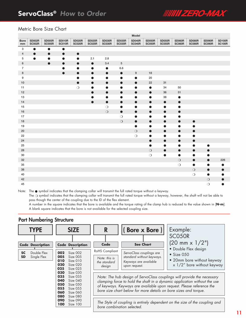
ServoClass® How to Order
Note: The l symbol indicates that the clamping collar will transmit the full rated torque without a keyway. The m symbol indicates that the clamping collar will transmit the full rated torque without a keyway, however, the shaft will not be able to
pass though the center of the coupling due to the ID of the flex element. A number in the square indicates that the bore is available and the torque rating of the clamp hub is reduced to the value shown in [N-m]. A blank square indicates that the bore is not available for the selected coupling size.
Metric Bore Size ChartModel
Bore mm
SD002R SC002R
SD005R SC005R
SD010R SC010R
SD020R SC020R
SD025R SC025R
SD030R SC030R
SD035R SC035R
SD040R SC040R
SD050R SC050R
SD055R SC055R
SD060R SC060R
SD080R SC080R
SD090R SC090R
SD100R SC100R
3 l l l
4 l l l l
5 l l l l 2.1 2.8
6 l l l l 3.4 5
7 l l l l 6.6
8 l l l l l 9 18
9 l l l l l 20
10 l l l l l 22 31
11 m l l l l l 34 50
12 l l l l l 36 51
13 l l l l l 38 l
14 l l l l l l l
15 m l l l l l
16 m l l l l l
17 m l l l l
18 m l l l l l
19 l l l l l
20 m l l l l
22 m l l l l
24 l l l l
25 l l l l l
28 m l l l l
30 m l l l l
32 m l l 226
35 m l l l
38 m l l
40 m l l
42 m l
45 m l
Part Numbering Structure
Example: SC050R (20 mm x 1/2")• Double Flex design• Size 050• 20mm bore without keyway
x 1/2” bore without keyway
TYPE R
SC Double Flex SD Single Flex
Code
Note: this is the standard
design
RoHS Compliant
Code Description
SIZE
002 Size 002 005 Size 005 010 Size 010 020 Size 020025 Size 025 030 Size 030 035 Size 035 040 Size 040 050 Size 050 055 Size 055 060 Size 060 080 Size 080 090 Size 090 100 Size 100
Code Description
( Bore x Bore )
See Chart
ServoClass couplings are standard without keyways.Keyways are available upon request.
Note: The hub design of ServoClass couplings will provide the necessary clamping force to hold the shaft in a dynamic application without the use of keyways. Keyways are available upon request. Please reference the bore size chart below for more details on bore sizes and torque.
The Style of coupling is entirely dependent on the size of the coupling and bore combination selected.
11

ServoClass® CouplingsDesigned for demanding servomotor applications. Zero backlash, high torsional stiffness coupling. Features flexible metal discs and keyless clamp-type mounting hubs. Couplings are RoHS compliant.
Schmidt® Offset CouplingsSchmidt® Offset Couplings are designed to handle high amounts of parallel offset up to 17.00". Standard models with torque capacities up to 459,000 in-lbs.
Overload Safety CouplingsTorq-Tender® Couplings provide reliable overload protection in any mechanical power transmission system. Torque ranges from 2 to 3000 in-lbs.
ETP® Shaft Locking ConnectionsDesigned for quick, easy and accurate assembly of mounted shaft components. Both inch and metric bore connections are available from stock.
Adjustable Speed DrivesEasy to install and maintenance free. Zero-Max Drives offer infinitely variable speeds from 0 rpm to 1/4 of input rpm. 5 models with torque ranges from 12 in-lbs to 200 in-lbs.
Crown® Gear DrivesCrown® Gear Drives are available with 1:1 and 2:1 ratios. High quality AGMA class 10 spiral bevel gears. Stainless steel shafts and aluminum housings are standard on all Crown® Gear Drives.
Roh’lix® Linear ActuatorsRoh’Lix® Linear Actuators convert rotary motion into precise linear motion. Available in five models. Roh’Lix® actuators have thrust ratings from 5 to 200 lbs. All models feature built in overload protection.
CD® CouplingsThese high performance couplings out last bellows and steel disc design couplings. The unique design of the composite disc enables the CD® Couplings to withstand punishing applications and deliver high precision performance.
Control-Flex® CouplingsControl-Flex® Couplings are zero backlash couplings designed for encoder and instrumentation type applications.
OHLA® Overhung Load AdaptersOHLA® Overhung Load Adapters are designed to eliminate radial and axial loads from a hydraulic pump or motor. 11 models available for mounts from SAE A to SAE F.
Warranty. Zero-Max, Inc. the manufacturer, warrants that for a period of 12 months from date of shipment it will repair, or at its option, replace any new apparatus which proves defective in material or workmanship, or which does not conform to applicable drawings and specifications approved by the manufacturer. All repairs and replacements shall be F.O.B. factory. All claims must be made in writing to the manufacturer. • In no event and under no circumstances shall manufacturer be liable for (a) damages in shipment; (b) failures or damages due to misuse, abuse, improper installation or abnormal conditions of temperature, dirt, water or corrosives; (c) failures due to operation, intentional or otherwise, above rated capacities, and (d) non-authorized expenses for removal, inspection, transportation, repair or rework. Nor shall manufacturer ever be liable for consequential and incidental damages, or in any amount greater than the purchase price of the apparatus. • Zero Max, Inc. reserves the right to discontinue models or to change specifications at any time without notice. No discontinuance or change shall create any liability on the part of Zero-Max, Inc. in respect to its products in the hands of customers or products on order not incorporating such changes even though delivered after any such change. • This warranty is in LIEU OF ALL OTHER WARRANTIES, EXPRESS OR IMPLIED, INCLUDING (BUT NOT LIMITED TO) ANY IMPLIED WARRANTIES OF MERCHANTABILITY OR FITNESS FOR A PARTICULAR PURPOSE. THE TERMS OF THIS WARRANTY CONSTITUTE ALL BUYER’S OR USER’S SOLE AND EXCLUSIVE REMEDY, AND ARE IN LIEU OF ANY RIGHT TO RECOVER FOR NEGLIGENCE, BREACH OF WARRANTY, STRICT TORT LIABILITY OR UPON ANY OTHER THEORY. Any legal proceedings arising out of the sale or use of this apparatus must be commenced within 18 months of the date of purchase. • CAUTION: Rotating equipment must be guarded. Also refer to OSHA specifications and recommendations. • Zero-Max®, CD®, ETP®, ServoClass®, Torq-Tender®, Control-Flex®, Posi-Lok®, Roh’Lix® , Crown® , Schmidt® and OHLA® are registered trademarks of Zero-Max, Inc. In U.S.A.
©Zero-Max 2016 Printed in U.S.A.
13200 Sixth Avenue North, Plymouth, Minnesota 55441-5509Phone 800.533.1731 763.546.4300 FAX 763.546.8260
zero-max.com