SERVO MOTOR'S INSTRUCTION MANUAL FOR HYDRAULIC …...The Ultract series of permanent magnet AC servo...
12
SERVO MOTOR'S INSTRUCTION MANUAL FOR HYDRAULIC SYSTEM
Transcript of SERVO MOTOR'S INSTRUCTION MANUAL FOR HYDRAULIC …...The Ultract series of permanent magnet AC servo...

SERVO MOTOR'S INSTRUCTION MANUAL
FOR HYDRAULIC SYSTEM
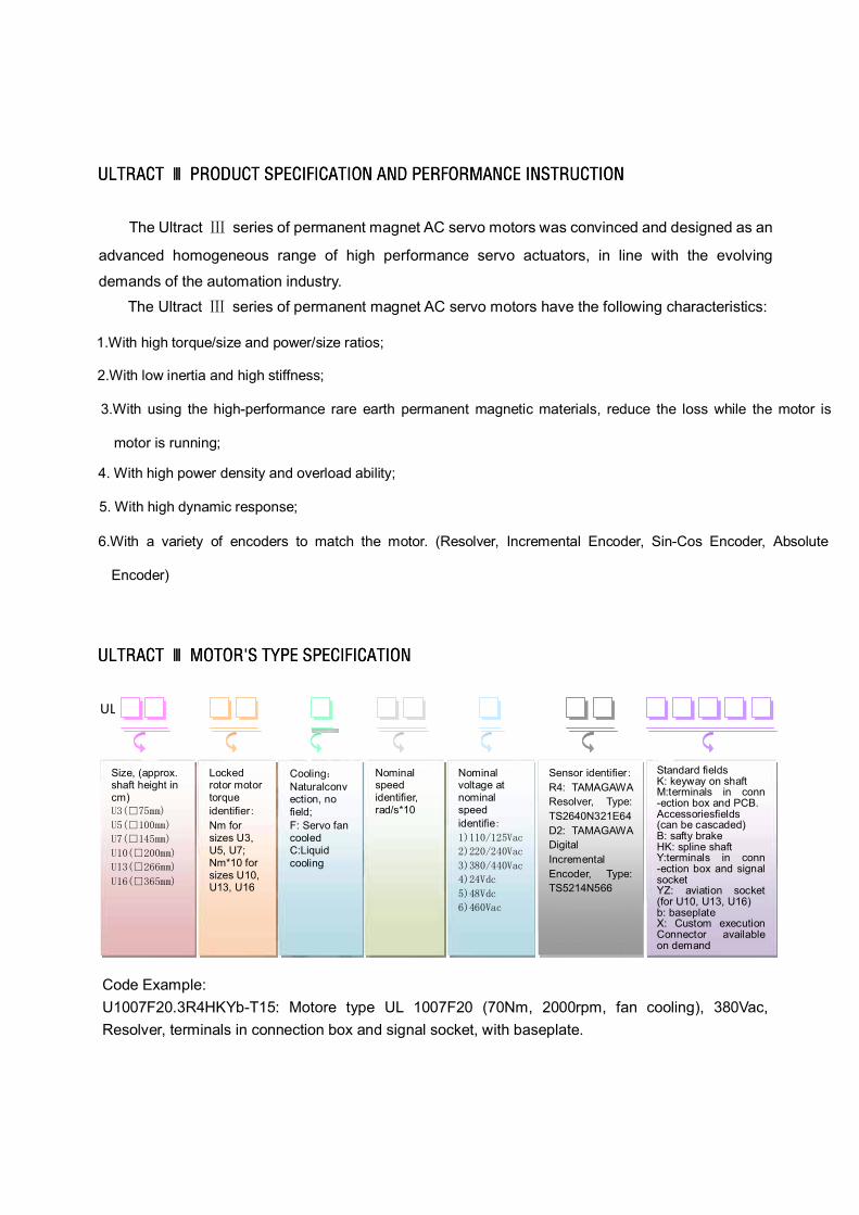
The Ultract series of permanent magnet AC servo motors have the following characteristics:
1.With high torque/size and power/size ratios;
2.With low inertia and high stiffness;
3.With using the high-performance rare earth permanent magnetic materials, reduce the loss while the motor is
motor is running;
4. With high power density and overload ability;
5. With high dynamic response;
6.With a variety of encoders to match the motor. (Resolver, Incremental Encoder, Sin-Cos Encoder, Absolute
Encoder)
UL
Code Example: U1007F20.3R4HKYb-T15: Motore type UL 1007F20 (70Nm, 2000rpm, fan cooling), 380Vac, Resolver, terminals in connection box and signal socket, with baseplate.
Standard fields K: keyway on shaft M:terminals in conn -ection box and PCB. Accessoriesfields (can be cascaded) B: safty brake HK: spline shaft Y:terminals in conn -ection box and signal socket YZ: aviation socket (for U10, U13, U16) b: baseplate X: Custom execution Connector available on demand
Sensor identifierR4: TAMAGAWA Resolver, Type: TS2640N321E64 D2: TAMAGAWA Digital Incremental Encoder, Type: TS5214N566
Nominal voltage at nominal speed identifie
Nominal speed identifier, rad/s*10
Locked rotor motor torque identifierNm for sizes U3, U5, U7; Nm*10 for sizes U10, U13, U16
CoolingNaturalconvection, no field; F: Servo fan cooled C:Liquid cooling
Size, (approx. shaft height in cm)
The Ultract series of permanent magnet AC servo motors was convinced and designed as an
advanced homogeneous range of high performance servo actuators, in line with the evolving
demands of the automation industry.
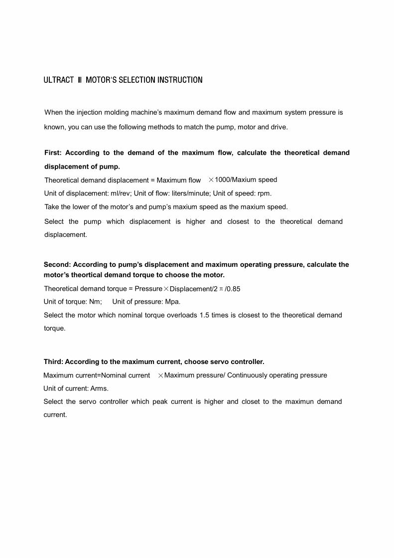
When the injection molding machine’s maximum demand flow and maximum system pressure is
known, you can use the following methods to match the pump, motor and drive.
First: According to the demand of the maximum flow, calculate the theoretical demand
displacement of pump.
Theoretical demand displacement = Maximum flow 1000/Maxium speed
Unit of displacement: ml/rev; Unit of flow: liters/minute; Unit of speed: rpm.
Take the lower of the motor’s and pump’s maxium speed as the maxium speed.
Select the pump which displacement is higher and closest to the theoretical demand
displacement.
Second: According to pump’s displacement and maximum operating pressure, calculate the motor’s theortical demand torque to choose the motor.
Theoretical demand torque = Pressure Displacement/2 /0.85
Unit of torque: Nm; Unit of pressure: Mpa.
Select the motor which nominal torque overloads 1.5 times is closest to the theoretical demand
torque.
Third: According to the maximum current, choose servo controller.
Maximum current=Nominal current Maximum pressure/ Continuously operating pressure
Unit of current: Arms.
Select the servo controller which peak current is higher and closet to the maximun demand
current.
注塑机专用电机选型手册
2
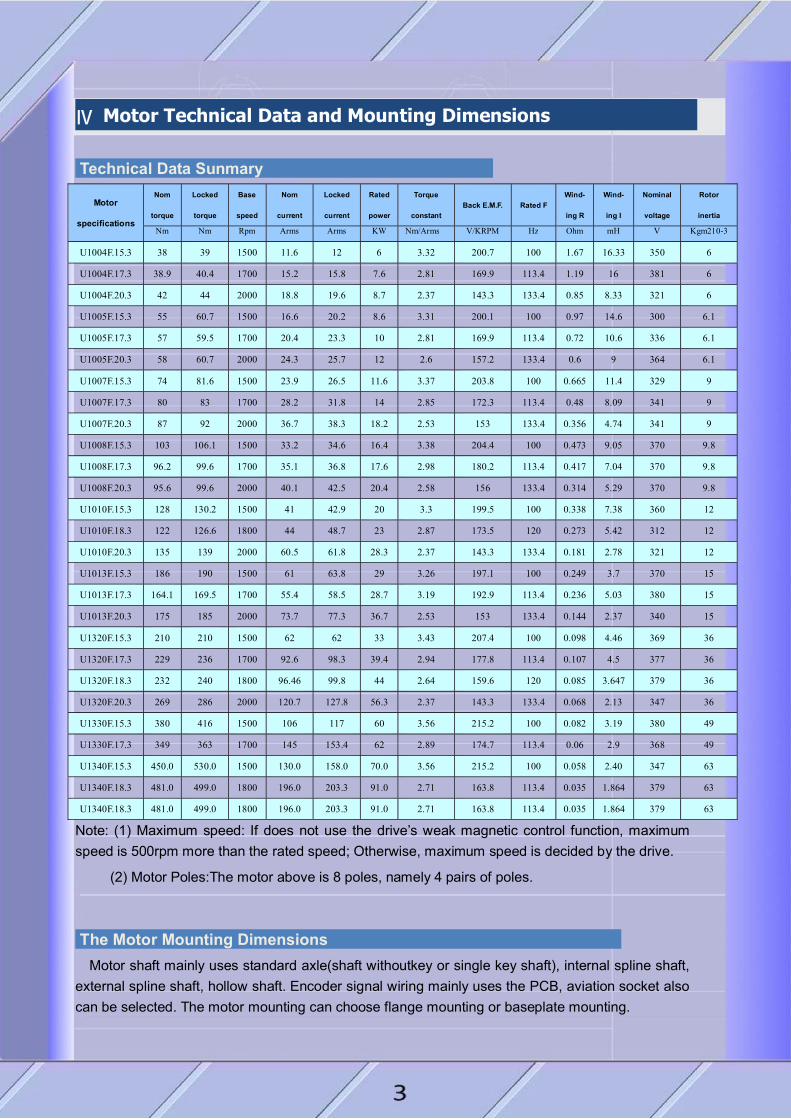
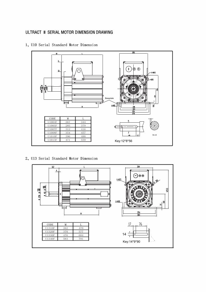
Ⅳ Motor Technical Data and Mounting Dimensions
Technical Data Sunmary
Motor
specifications
Nom
torque
Locked
torque
Base
speed
Nom
current
Locked
current
Rated
power
Torque
constant Back E.M.F. Rated F
Wind-
ing R
Wind-
ing I
Nominal
voltage
Rotor
inertia
Nm Nm Rpm Arms Arms KW Nm/Arms V/KRPM Hz Ohm mH V Kgm210-3
U1004F.15.3 38 39 1500 11.6 12 6 3.32 200.7 100 1.67 16.33 350 6
U1004F.17.3 38.9 40.4 1700 15.2 15.8 7.6 2.81 169.9 113.4 1.19 16 381 6
U1004F.20.3 42 44 2000 18.8 19.6 8.7 2.37 143.3 133.4 0.85 8.33 321 6
U1005F.15.3 55 60.7 1500 16.6 20.2 8.6 3.31 200.1 100 0.97 14.6 300 6.1
U1005F.17.3 57 59.5 1700 20.4 23.3 10 2.81 169.9 113.4 0.72 10.6 336 6.1
U1005F.20.3 58 60.7 2000 24.3 25.7 12 2.6 157.2 133.4 0.6 9 364 6.1
U1007F.15.3 74 81.6 1500 23.9 26.5 11.6 3.37 203.8 100 0.665 11.4 329 9
U1007F.17.3 80 83 1700 28.2 31.8 14 2.85 172.3 113.4 0.48 8.09 341 9
U1007F.20.3 87 92 2000 36.7 38.3 18.2 2.53 153 133.4 0.356 4.74 341 9
U1008F.15.3 103 106.1 1500 33.2 34.6 16.4 3.38 204.4 100 0.473 9.05 370 9.8
U1008F.17.3 96.2 99.6 1700 35.1 36.8 17.6 2.98 180.2 113.4 0.417 7.04 370 9.8
U1008F.20.3 95.6 99.6 2000 40.1 42.5 20.4 2.58 156 133.4 0.314 5.29 370 9.8
U1010F.15.3 128 130.2 1500 41 42.9 20 3.3 199.5 100 0.338 7.38 360 12
U1010F.18.3 122 126.6 1800 44 48.7 23 2.87 173.5 120 0.273 5.42 312 12
U1010F.20.3 135 139 2000 60.5 61.8 28.3 2.37 143.3 133.4 0.181 2.78 321 12
U1013F.15.3 186 190 1500 61 63.8 29 3.26 197.1 100 0.249 3.7 370 15
U1013F.17.3 164.1 169.5 1700 55.4 58.5 28.7 3.19 192.9 113.4 0.236 5.03 380 15
U1013F.20.3 175 185 2000 73.7 77.3 36.7 2.53 153 133.4 0.144 2.37 340 15
U1320F.15.3 210 210 1500 62 62 33 3.43 207.4 100 0.098 4.46 369 36
U1320F.17.3 229 236 1700 92.6 98.3 39.4 2.94 177.8 113.4 0.107 4.5 377 36
U1320F.18.3 232 240 1800 96.46 99.8 44 2.64 159.6 120 0.085 3.647 379 36
U1320F.20.3 269 286 2000 120.7 127.8 56.3 2.37 143.3 133.4 0.068 2.13 347 36
U1330F.15.3 380 416 1500 106 117 60 3.56 215.2 100 0.082 3.19 380 49
U1330F.17.3 349 363 1700 145 153.4 62 2.89 174.7 113.4 0.06 2.9 368 49
U1340F.15.3 450.0 530.0 1500 130.0 158.0 70.0 3.56 215.2 100 0.058 2.40 347 63
U1340F.18.3 481.0 499.0 1800 196.0 203.3 91.0 2.71 163.8 113.4 0.035 1.864 379 63
U1340F.18.3 481.0 499.0 1800 196.0 203.3 91.0 2.71 163.8 113.4 0.035 1.864 379 63
Note: (1) Maximum speed: If does not use the drive’s weak magnetic control function, maximum speed is 500rpm more than the rated speed; Otherwise, maximum speed is decided by the drive.
(2) Motor Poles:The motor above is 8 poles, namely 4 pairs of poles.
The Motor Mounting Dimensions Motor shaft mainly uses standard axle(shaft withoutkey or single key shaft), internal spline shaft,
external spline shaft, hollow shaft. Encoder signal wiring mainly uses the PCB, aviation socket also can be selected. The motor mounting can choose flange mounting or baseplate mounting.
King's
Rectangle
Baseplate
14
Key:14*9*90
Key:12*8*56

CODE M L
CODE M L
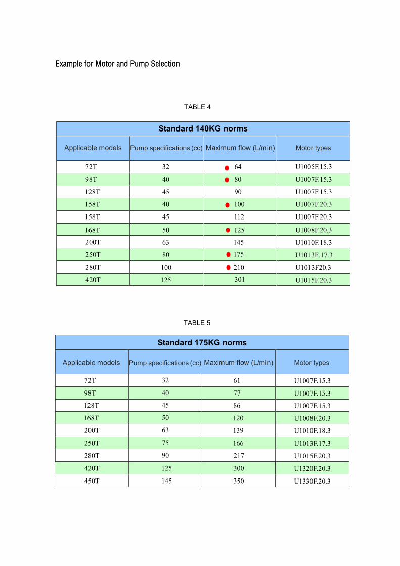
Standard 140KG norms
Applicable models Pump specifications (cc) Maximum flow (L/min) Motor types
72T 32 64
U1005F.15.3
98T 40 80
U1007F.15.3
128T 45 90
U1007F.15.3
158T 40 100
U1007F.20.3
158T 45 112 U1007F.20.3
168T 50 125 U1008F.20.3
200T 63 145 U1010F.18.3
250T 80 175 U1013F.17.3
280T 100 210 U1013F20.3
420T 125 301 U1015F.20.3
Standard 175KG norms
72T 32 61 U1007F.15.3
98T 40 77 U1007F.15.3
128T 45 86 U1007F.15.3
168T 50 120 U1008F.20.3
200T 63 139 U1010F.18.3
250T 75 166 U1013F.17.3
280T 90 217 U1015F.20.3
Applicable models Pump specifications (cc) Maximum flow (L/min) Motor types
TABLE 4
TABLE 5
420T 300 U1320F.20.3
450T 350 U1330F.20.3
125
145
King's
Oval
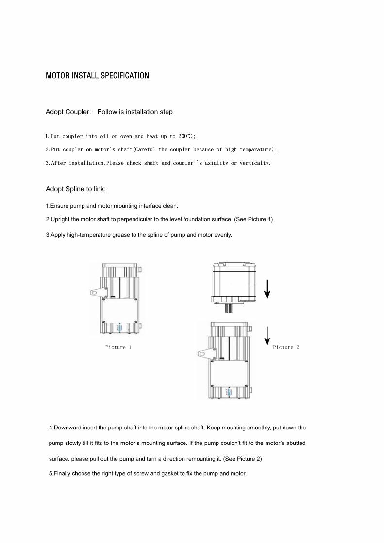
2.Upright the motor shaft to perpendicular to the level foundation surface. (See Picture 1)
1.Ensure pump and motor mounting interface clean.
3.Apply high-temperature grease to the spline of pump and motor evenly.
4.Downward insert the pump shaft into the motor spline shaft. Keep mounting smoothly, put down the
pump slowly till it fits to the motor’s mounting surface. If the pump couldn’t fit to the motor’s abutted
surface, please pull out the pump and turn a direction remounting it. (See Picture 2)
5.Finally choose the right type of screw and gasket to fix the pump and motor.
Adopt Coupler: Follow is installation step
Adopt Spline to link:
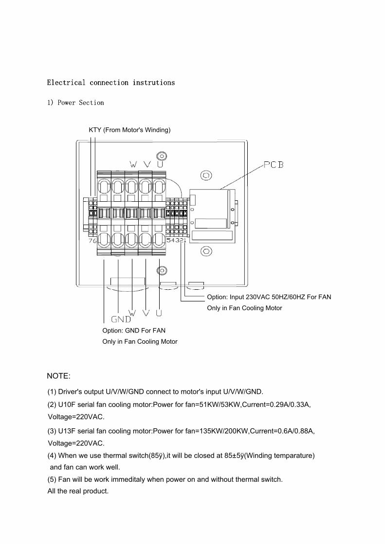
KTY (From Motor's Winding)
Option: Input 230VAC 50HZ/60HZ For FAN
Only in Fan Cooling Motor
Option: GND For FAN
Only in Fan Cooling Motor
(1) Driver's output U/V/W/GND connect to motor's input U/V/W/GND.
NOTE:
(2) U10F serial fan cooling motor:Power for fan=51KW/53KW,Current=0.29A/0.33A,
Voltage=220VAC.
(3) U13F serial fan cooling motor:Power for fan=135KW/200KW,Current=0.6A/0.88A,
Voltage=220VAC.
(4) When we use thermal switch(85ÿ),it will be closed at 85±5ÿ(Winding temparature)
(5) Fan will be work immeditaly when power on and without thermal switch.
and fan can work well.
All the real product.
The PCB pins
number Resolver
Digital incremental
encoder
1 Resex+ +Vcc
2 Resex- 0V
3 Sin+ V-
4 Sin- V+
5 Cos+ U+
6 Cos- U -
7 -- A+
8 -- A -
9 -- Z -
10 -- Z+
11 -- W+
12 -- W-
13 -- B -
14 -- B+
15 PTC+ Output PTC+ Output
16 PTC- Output PTC- Output
17 PTC+ Input PTC+ Input
18 PTC- Input PTC- Input
Aviation socket pins
number
ResolverDigital
incremental encoder
1 -- +Vcc2 -- 0V
3 -- V-
4 Sin- V+
5 Cos+ U+ 6 Cos- U-
7 Resex+ A+
8 KTY+ A-
9 KTY- Z -
10 Resex- Z+
11 -- W+
12 -- W-
13 -- B -
14 Sin+ B+
15 -- PTC+
16 PTC+ PTC-/KTY-
17 PTC- KTY+
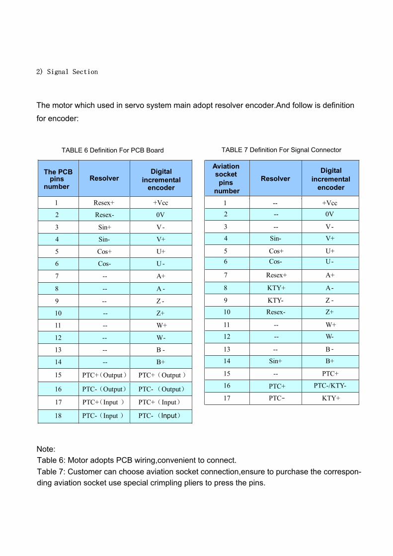
TABLE 6 Definition For PCB Board TABLE 7 Definition For Signal Connector
The motor which used in servo system main adopt resolver encoder.And follow is definition
for encoder:
Note:Table 6: Motor adopts PCB wiring,convenient to connect.Table 7: Customer can choose aviation socket connection,ensure to purchase the correspon-ding aviation socket use special crimpling pliers to press the pins.