
Servo Motor - Instruction Manual SH(NA)-3181-D (03.00)
369
General-Purpose AC Servo Servo Motor Instruction Manual D
-
Upload
eddie-reconco -
Category
Documents
-
view
262 -
download
11
Transcript of Servo Motor - Instruction Manual SH(NA)-3181-D (03.00)

8/10/2019 Servo Motor - Instruction Manual SH(NA)-3181-D (03.00)
http://slidepdf.com/reader/full/servo-motor-instruction-manual-shna-3181-d-0300 1/368
General-Purpose AC Servo
Servo Motor
Instruction Manual
D

8/10/2019 Servo Motor - Instruction Manual SH(NA)-3181-D (03.00)
http://slidepdf.com/reader/full/servo-motor-instruction-manual-shna-3181-d-0300 2/368
A - 1
Safety Instructions(Always read these instructions before using the equipment.)
Do not attempt to install, operate, maintain or inspect the servo amplifier and servo motor until you have readthrough this Instruction Manual, MELSERVO Servo Amplifier Installation Guide/Instruction Manual andappended documents carefully and can use the equipment correctly. Do not use the servo amplifier and servomotor until you have a full knowledge of the equipment, safety information and instructions.In this Installation guide, the safety instruction levels are classified into "WARNING" and "CAUTION".
WARNING Indicates that incorrect handling may cause hazardous conditions,resulting in death or severe injury.
CAUTIONIndicates that incorrect handling may cause hazardous conditions,
resulting in medium or slight injury to personnel or may cause physicaldamage.
Note that the CAUTION level may lead to a serious consequence according to conditions. Please follow theinstructions of both levels because they are important to personnel safety.What must not be done and what must be done are indicated by the following diagrammatic symbols:
: Indicates what must not be done. For example, "No Fire" is indicated by .
: Indicates what must be done. For example, grounding is indicated by .
In this Instruction Manual, instructions at a lower level than the above, instructions for other functions, and soon are classified into "POINT". After reading this installation guide, always keep it accessible to the operator.

8/10/2019 Servo Motor - Instruction Manual SH(NA)-3181-D (03.00)
http://slidepdf.com/reader/full/servo-motor-instruction-manual-shna-3181-d-0300 3/368
A - 2
1. To prevent electric shock, note the following:
WARNING• Before wiring or inspection, switch power off and wait for more than 10 minutes. Then, confirm the voltage
is safe with voltage tester. Otherwise, you may get an electric shock.
• Connect the servo amplifier and servo motor to ground.
• Any person who is involved in wiring and inspection should be fully competent to do the work.
• Do not attempt to wire the servo amplifier and servo motor until they have been installed. Otherwise, youmay get an electric shock.
• Operate the switches with dry hand to prevent an electric shock.
• The cables should not be damaged, stressed loaded, or pinched. Otherwise, you may get an electricshock.
2. To prevent fire, note the following:
CAUTION• Do not install the servo motor on or near combustibles. Otherwise a fire may cause.
3. To prevent injury, note the follow
CAUTION• Only the voltage specified in the Instruction Manual should be applied to each terminal, Otherwise, a burst,
damage, etc. may occur.
• Connect the terminals correctly to prevent a burst, damage, etc.
• Ensure that polarity (+, − ) is correct. Otherwise, a burst, damage, etc. may occur.
• During power-on or for some time after power-off, do not touch the servo motor, etc. Their temperaturesmay be high and you may get burnt.

8/10/2019 Servo Motor - Instruction Manual SH(NA)-3181-D (03.00)
http://slidepdf.com/reader/full/servo-motor-instruction-manual-shna-3181-d-0300 4/368
A - 3
4. Additional instructionsThe following instructions should also be fully noted. Incorrect handling may cause a fault, injury, electricshock, etc.
(1) Transportation and installation
CAUTION• Transport the products correctly according to their weights.• Use the eye-bolt of the servo motor to only transport the servo motor and do not use it to transport in the
condition to have installed a servo motor on the machine.• Stacking in excess of the specified number of products is not allowed.• Do not carry the motor by the cables, shaft or encoder.• Install the servo amplifier in a load-bearing place in accordance with the Instruction Manual.• Do not climb or stand on servo equipment. Do not put heavy objects on equipment.• The servo motor must be installed in the specified direction.• Do not install or operate the servo motor which has been damaged or has any parts missing.• Do not block the intake/exhaust port of the servo motor which has a cooling fan.
• Provide adequate protection to prevent screws and other conductive matter, oil and other combustiblematter from entering the servo motor.• Do not drop or strike servo motor. Isolate from all impact loads.• Use the servo motor under the following environmental conditions:
ConditionsEnvironment Servo Motor [° C] 0 to +40 (non-freezing) Ambient
temperature [° F] 32 to 104 (non-freezing) Ambient humidity 80%RH or less (non-condensing)
[° C] − 15 to +70 (non-freezing)Storagetemperature [° F] 5 to 158 (non-freezing)Storage humidity 90%RH or less (non-condensing) Ambience Indoors (no direct sunlight) Free from corrosive gas, flammable gas, oil mist, dust and dirt Altitude Max. 1000m (3280 ft) above sea level
HC-AQ series
HC-KF seriesHC-MF seriesHA-FF series
HC-UF13 to 73
HC-KFS seriesHC-MFS series
HC-UFS13 to 73
X,Y:49
HC-SF81HC-SF52 to 152HC-SF53 to 153
HC-RF seriesHC-UF72 · 152
HC-SFS81HC-SFS52 to 152HC-SFS53 to 153
HC-RFS seriesHC-UFS72 · 152
X,Y:24.5
HC-SF121 · 201HC-SF202 · 352HC-SF203 · 353
HC-UF202 to 502
HC-SFS121 · 201HC-SFS202 · 352HC-SFS203 · 353
HC-UFS202
X:24.5Y:49
HC-SF301HC-SF501· 702 HC-SFS301 X:24.5
Y:29.4
HA-LH11K2 to 22K2 X:11.7Y:29.4
[m/s 2]
HA-LF30K2 · HA-LF30K24 to 55K24 X,Y:9.8
HC-AQ series
HC-KF seriesHC-MF series
HA-FF seriesHC-UF series
HC-KFS seriesHC-MFS seriesHA-FFS series
X,Y:161
HC-SF81HC-SF52 to 152HC-SF53 to 153
HC-RF seriesHC-UF72 · 152
HC-SFS81HC-SFS52 to 152HC-SFS53 to 153
HC-RFS seriesHC-UFS72 · 152
X,Y:80
HC-SF121 · 201HC-SF202 · 352HC-SF203 · 353
HC-UF202 to 502
HC-SFS121 · 201HC-SFS202 · 352HC-SFS203 · 353
HC-UFS202
X:80Y:161
HC-SF301HC-SF501· 702 HC-SFS301 X:80
Y:96
HA-LH11K2 to 22K2 X:38.4Y:96.5
Vibration
[ft/s 2]
HA-LF30K2 · HA-LF30K24 to 55K24 X,Y:32

8/10/2019 Servo Motor - Instruction Manual SH(NA)-3181-D (03.00)
http://slidepdf.com/reader/full/servo-motor-instruction-manual-shna-3181-d-0300 5/368
A - 4
CAUTION• Securely attach the servo motor to the machine. If attach insecurely, the servo motor may come off during
operation.
• The servo motor with reduction gear must be installed in the specified direction to prevent oil leakage.
• For safety of personnel, always cover rotating and moving parts.
• Never hit the servo motor or shaft, especially when coupling the servo motor to the machine. The encoder may become faulty.
• Do not subject the servo motor shaft to more than the permissible load. Otherwise, the shaft may break.
• When the equipment has been stored for an extended period of time, consult Mitsubishi.
(2) Wiring
CAUTION• Wire the equipment correctly and securely. Otherwise, the servo motor may misoperate.
• Do not install a power capacitor, surge absorber or radio noise filter (FR-BIF option) between the servomotor and servo amplifier.
• Connect the output terminals (U, V, W) correctly. Otherwise, the servo motor will operate improperly.
• Do not connect AC power directly to the servo motor. Otherwise, a fault may occur.
(3) Test run adjustment
CAUTION• Before operation, check the parameter settings. Improper settings may cause some machines to perform
unexpected operation.
• The parameter settings must not be changed excessively. Operation will be instable.
8/10/2019 Servo Motor - Instruction Manual SH(NA)-3181-D (03.00)
http://slidepdf.com/reader/full/servo-motor-instruction-manual-shna-3181-d-0300 6/368
A - 5
(4) Usage
CAUTION• Provide an external emergency stop circuit to ensure that operation can be stopped and power switched
off immediately.
• Any person who is involved in disassembly and repair should be fully competent to do the work.
• Do not modify the equipment.
• Use the servo amplifier with the specified servo motor.
• The electromagnetic brake on the servo motor is designed to hold the motor shaft and should not be usedfor ordinary braking.
• For such reasons as service life and mechanical structure (e.g. where a ballscrew and the servo motor arecoupled via a timing belt), the electromagnetic brake may not hold the motor shaft. To ensure safety,
install a stopper on the machine side.
(5) Corrective actions
CAUTION• When it is assumed that a hazardous condition may take place at the occur due to a power failure or a
product fault, use a servo motor with electromagnetic brake or an external brake mechanism for thepurpose of prevention.
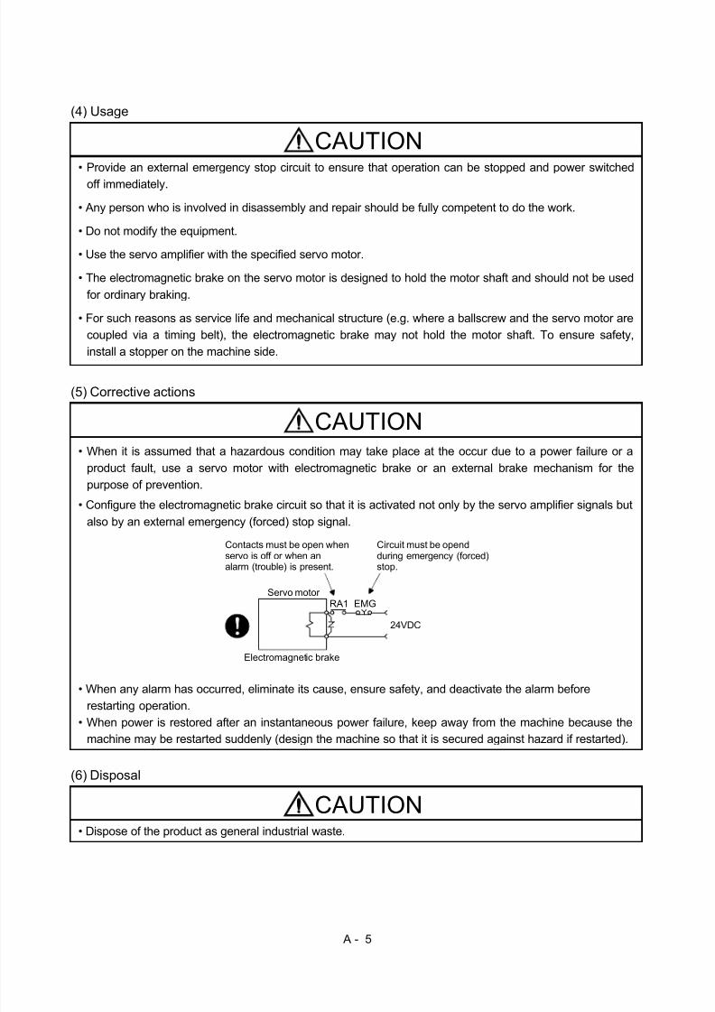
• Configure the electromagnetic brake circuit so that it is activated not only by the servo amplifier signals butalso by an external emergency (forced) stop signal.
EMGRA1
24VDC
Contacts must be open whenservo is off or when analarm (trouble) is present.
Electromagnetic brake
Servo motor
Circuit must be opendduring emergency (forced)stop.
• When any alarm has occurred, eliminate its cause, ensure safety, and deactivate the alarm before
restarting operation.• When power is restored after an instantaneous power failure, keep away from the machine because the
machine may be restarted suddenly (design the machine so that it is secured against hazard if restarted).
(6) Disposal
CAUTION• Dispose of the product as general industrial waste.

8/10/2019 Servo Motor - Instruction Manual SH(NA)-3181-D (03.00)
http://slidepdf.com/reader/full/servo-motor-instruction-manual-shna-3181-d-0300 7/368
A - 6
COMPLIANCE WITH EC DIRECTIVES1. WHAT ARE EC DIRECTIVES? The EC Directives were issued to standardize the regulations of the EU countries and ensure smoothdistr ibution of safety-guaranteed products. In the EU countries, the Machinery Directive (effective in J anuary, 1995), EMC Directive (effective in J anuary, 1996) and Low Voltage Directive (effective in J anuary, 1997) of the EC Directives require that products to be sold should meet their fundamental safetyrequirements and carry the CE marks (CE marking). CE marking applies to machines and equipmentinto which servo amplifiers have been installed. The servo amplifiers do not function independently but are designed for use with machines andequipment. Therefore, the CE marking does not apply to the servo amplifiers but applies to the machines andequipment into which the servo amplifiers are installed. This servo amplifier conforms to the standards related to the Low Voltage Directive to facili tate CEmarking on machines and equipment into which the servo amplifiers will be installed. To ensure ease of compliance with the EMC Directive, Mitsubishi Electric prepared the "EMC INSTALLATION
GUIDELINES" (IB(NA)67310) which provides servo amplifier installation, control box making and otherprocedures. Please contact your sales representative.
2. PRECAUTIONS FOR COMPLIANCEUse the servo motor compatible with the EN Standard.Unless otherwise specified, the handling, performance, specifications and others of the EN Standard-compatible models are the same as those of the standard models. To comply with the EN Standard, also observe the following items strictly.(1) Wiring
(a) Use a fixed terminal block to connect the power supply lead of the servo motor to the servoamplifier. Do not connect cables directly.
Terminal block
(b) Use the servo motor side power connector which complies with the EN Standard. The EN Standard-compliant power connector sets are available from us as options.
Power Connector Set Model Servo Motor ModelMR-PWCF HC-FF C(B)-UEMR-PWCNS1 HC-SF81(B)
HC-SF 52(B) to 152(B)HC-SF 53(B) to 153(B)HC-RF103(B) to 203(B)HC-UF72(B) • 152(B)
HC-SFS81(B)HC-SF S52(B) to 152(B)HC-SF S53(B) to 153(B)HC-RFS103(B) to 203(B)HC-UFS72(B) • 152(B)
M R-P WCN S2 H C-SF 121(B) to 301(B)HC-SF 202(B) to 352(B)HC-SF 203(B) • 353(B)HC-RF353(B) • 503(B)HC-UF202(B) to 502(B)HC-SF S121(B) to 301(B)HC-SF S202(B) to 352(B)HC-SF S203(B) • 353(B)HC-UFS202(B)
MR-PWCNS3 HC-SF702(B)
(2) Installation The flange of the machine mounted with the HC-MF/HC-K F/HC-AQ/HC-MFS/HC-K FS must beconnected to the earth.
8/10/2019 Servo Motor - Instruction Manual SH(NA)-3181-D (03.00)
http://slidepdf.com/reader/full/servo-motor-instruction-manual-shna-3181-d-0300 8/368
A - 7
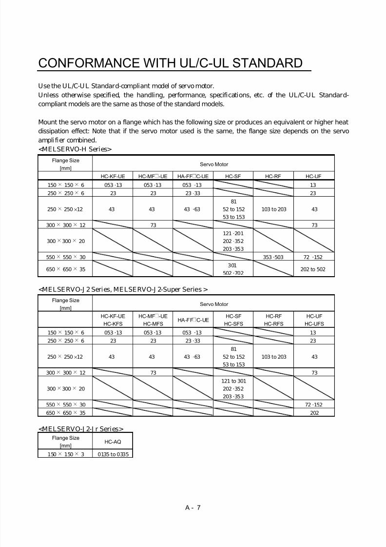
CONFORMANCE WITH UL/C-UL STANDARD
Use the UL/C-U L Standard-compliant model of servo motor.
Unless otherwise specified, the handling, performance, specifications, etc. of the UL/C-UL Standard-compliant models are the same as those of the standard models.
Mount the servo motor on a flange which has the following size or produces an equivalent or higher heatdissipation effect: Note that if the servo motor used is the same, the flange size depends on the servoamplifier combined.<MELSERVO-H Series>
Flange Size[mm]
Servo Motor
HC-KF-UE HC-MF -UE HA-FF C-UE HC-SF HC-RF HC-UF
150 150 6 053 13 053 13 053 13 13
250 250 6 23 23 23 33 23
250 250 × 12 43 43 43 6381
52 to 15253 to 153
103 to 203 43
300 300 12 73 73
300 300 20121 201202 352203 353
550 550 30 353 503 72 152
650 650 35 301
502 702 202 to 502
<MELSERVO-J 2 Series, MELSERVO-J 2-Super Series >Flange Size
[mm]Servo Motor
HC-KF-UEHC-KFS
HC-MF -UEHC-MFS
HA-FF C-UEHC-SF
HC-SFSHC-RF
HC-RFSHC-UF
HC-UFS
150 150 6 053 13 053 13 053 13 13
250 250 6 23 23 23 33 23
250 250 × 12 43 43 43 6381
52 to 15253 to 153
103 to 203 43
300 300 12 73 73
300 300 20121 to 301202 352203 353
550 550 30 72 152
650 650 35 202
<MELSERVO-J 2-J r Series>Flange Size
[mm]HC-AQ
150 150 3 0135 to 0335

8/10/2019 Servo Motor - Instruction Manual SH(NA)-3181-D (03.00)
http://slidepdf.com/reader/full/servo-motor-instruction-manual-shna-3181-d-0300 9/368
A - 8
MEMO

8/10/2019 Servo Motor - Instruction Manual SH(NA)-3181-D (03.00)
http://slidepdf.com/reader/full/servo-motor-instruction-manual-shna-3181-d-0300 10/368
CONTENTS
1. INTRODUCTION 1 - 1 to 1 -10
1.1 Servo Motor Features............................................................................................................................. 1 - 11.2 Model Name Make-up............................................................................................................................1 - 11.3 Parts Identification................................................................................................................................ 1 -10
2. INSTALLATION 2 - 1 to 2 - 6
2.1 Environmental conditions...................................................................................................................... 2 - 22.2 Installation orientation..........................................................................................................................2 - 32.3 Transportation ........................................................................................................................................ 2 - 3
2.4 Load mounting precautions................................................................................................................... 2 - 32.5 Permissible load for the shaft................................................................................................................2 - 42.6 Protection from oil and water................................................................................................................ 2 - 52.7 Cooling Fan ............................................................................................................................................. 2 - 6
3. CONNECTORS USED FOR SERVO MOTOR WIRING 3 - 1 to 3 -20
3.1 Makeups.................................................................................................................................................. 3 - 13.1.1 HC-K F(-UE), HC-MF(-UE), HA-FF, HC-UF3000r/min series....................................................3 - 13.1.2 HA-F F C-UE series........................................................................................................................3 - 13.1.3 HC-SF(S), HC-RF(S), HC-UF(S)2000r/min, HA-L H, HA-L F series...........................................3 - 9
3.1.4 HC-AQ series...................................................................................................................................3 -163.1.5 HC-K FS, HC-MFS, HC-UFS3000r/min series ............................................................................3 -17
3.2 IP65, EN Standard-Compliant Options..............................................................................................3 -183.3 Signal Arrangement of Encoder Connectors....................................................................................... 3 -20
4. INSPECTION 4 - 1 to 4 - 2
5. SPECIFICATIONS 5 - 1 to 5 -26
5.1 Standard Specifications ......................................................................................................................... 5 - 15.2 Torque Characteristics..........................................................................................................................5 -145.3 Servo Motors with Reduction Gears ....................................................................................................5- 215.4 Servo Motors with Special Shafts ........................................................................................................5- 25
5.4.1 Keyway.............................................................................................................................................5- 255.4.2 D cut................................................................................................................................................. 5- 265.4.3 Straight (HC-AQ)............................................................................................................................ 5- 26
6. CHARACTERISTICS 6 - 1 to 6 - 4
6.1 Electromagnetic Brake Characteristics ............................................................................................... 6 - 16.2 Vibration Rank ....................................................................................................................................... 6 - 4
8/10/2019 Servo Motor - Instruction Manual SH(NA)-3181-D (03.00)
http://slidepdf.com/reader/full/servo-motor-instruction-manual-shna-3181-d-0300 11/368
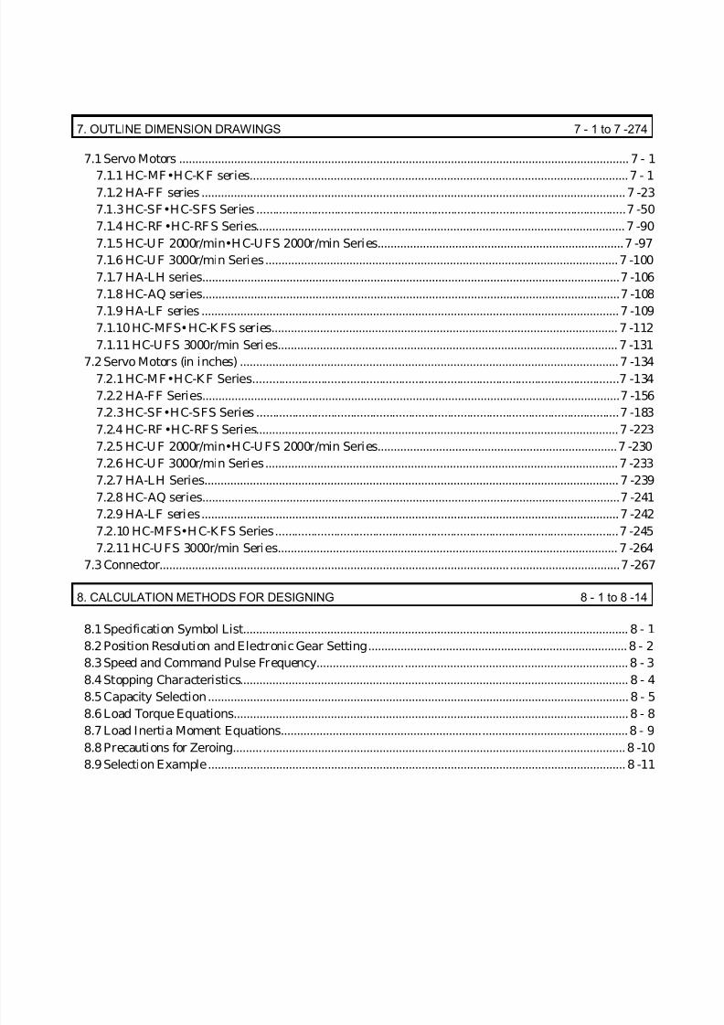
7. OUTLINE DIMENSION DRAWINGS 7 - 1 to 7 -274
7.1 Servo Motors ........................................................................................................................................... 7 - 1
7.1.1 HC-MF•H C-K F series.....................................................................................................................7 - 17.1.2 HA-FF series ...................................................................................................................................7 -237.1.3 HC-SF•HC-SFS Series ..................................................................................................................7 -507.1.4 HC-RF •HC-RF S Series..................................................................................................................7 -907.1.5 HC-U F 2000r/min•H C-U FS 2000r/min Series............................................................................7 -977.1.6 HC-U F 3000r/min Series.............................................................................................................7 -1007.1.7 HA-LH series.................................................................................................................................7 -1067.1.8 HC-AQ series.................................................................................................................................7 -1087.1.9 HA-LF series .................................................................................................................................7 -1097.1.10 HC-MFS•HC-K FS series........................................................................................................... 7 -1127.1.11 HC-U FS 3000r/min Series......................................................................................................... 7 -131
7.2 Servo Motors (in inches) .....................................................................................................................7 -1347.2.1 HC-MF•HC-K F Series.................................................................................................................7 -1347.2.2 HA-FF Series.................................................................................................................................7 -1567.2.3 HC-SF•HC-SFS Series ................................................................................................................7 -1837.2.4 HC-RF •HC-RF S Series................................................................................................................7 -2237.2.5 HC-U F 2000r/min•H C-U FS 2000r/min Series..........................................................................7 -2307.2.6 HC-U F 3000r/min Series.............................................................................................................7 -2337.2.7 HA-LH Series................................................................................................................................ 7 -2397.2.8 HC-AQ series.................................................................................................................................7 -2417.2.9 HA-LF series.................................................................................................................................7 -2427.2.10 HC-MFS•H C-K FS Series..........................................................................................................7 -2457.2.11 HC-U FS 3000r/min Series......................................................................................................... 7 -264
7.3 Connector..............................................................................................................................................7 -267
8. CALCULATION METHODS FOR DESIGNING 8 - 1 to 8 -14
8.1 Specification Symbol List....................................................................................................................... 8 - 18.2 Position Resolution and Electronic Gear Setting................................................................................8 - 28.3 Speed and Command Pulse Frequency................................................................................................8 - 38.4 Stopping Characteristics........................................................................................................................ 8 - 48.5 Capacity Selection.................................................................................................................................. 8 - 5
8.6 Load Torque Equations..........................................................................................................................8 - 88.7 Load Inertia Moment Equations...........................................................................................................8 - 98.8 Precautions for Zeroing.........................................................................................................................8 -108.9 Selection Example................................................................................................................................. 8 -11

8/10/2019 Servo Motor - Instruction Manual SH(NA)-3181-D (03.00)
http://slidepdf.com/reader/full/servo-motor-instruction-manual-shna-3181-d-0300 12/368
1 - 1
1. INTRODUCTION
1. INTRODUCTION
1.1 Servo Motor Features
Servo
Motor Series
Features
(Points Different from ConventionalProducts)
Positioning
Resolution[pulses/rev]
Rated
Speed[r/min] Capacity [kW]
Interchan-geable
Servo Motor Series
Compliance withOverseas Standards
EnvironmentalResistance
HC-KF 8192 Scheduled tocomply soon
IP44
HC-KFS
Low inertia, small capacity4 to 5times greater in inertia moment thanHC-MF(S).Equipped with absolute positiondetector as standard
1310723000 0.05 to0.4
HC-MFHC-MEHC-MH
EN StandardUL/C-UL Standard(Standard model iscompliant)
IP55
HC-MF 8192
EN StandardUL/C-UL Standard(HC-MF-UE iscompliant)
IP44
HC-MFS
Ultra low inertia, small capacity1.2 times higher in power rate thanHA-MEEquipped with absolute positiondetector as standard 131072
3000 0.05 to0.75 HA-ME
HA-MH EN StandardUL/C-UL Standard(Standard model iscompliant)
IP55
HC-SF 16384
HC-SFS
Middle inertia, middle capacity1.5 times higher in power rate thanHA-SEEquipped with absolute positiondetector as standard
131072
100020003000
0.5 to 7.0 HA-SE
HA-SH
EN StandardUL/C-UL Standard(Standard model iscompliant)
IP65
HC-RF 16384
HC-RFS
Low inertia, middle capacityAbout 3 times higher in power ratethan HA-LHEquipped with absolute positiondetector as standard
131072
3000 1.0 to 5.0
EN StandardUL/C-UL Standard(Standard model iscompliant)
IP65
Pancake type small capacityEquipped with absolute positiondetector as standard
8192 3000 0.1 to 0.75
IP65except
connectorsectionHC-UF
Pancake type middle capacity
Equipped with absolute positiondetector as standard
16384 2000 0.75 to 5.0
EN StandardUL/C-UL Standard(Standard model iscompliant)
IP65
Pancake type small capacityEquipped with absolute positiondetector as standard
3000 0.1 to 0.75
IP65except
connectorsectionHC-UFS
Pancake type middle capacityEquipped with absolute positiondetector as standard
131072
2000 0.75 to 5.0
EN StandardUL/C-UL Standard(Standard model iscompliant)
IP65
HA-LH Low inertia, Large capaci ty 16384 2000 11.0 to 22.0EN Standard(HA-LH-EC iscompliant)
J P44
HC-AQ 24VDC-compatible, ult racompact,
small capacity 8192 3000 0.01 to 0.03
EN Standard,UL/C-UL Standard(Standard model iscompliant)
IP55except for theshaft-through
portion and
connector Three-phase, 400VAC-compatible,low inerti a, large capacity
30.0 to 55.0HA-LF
Three-phase, 200VAC-compatible,low inerti a, large capacity
16384 200030.0
Scheduled to makeapplication IP44
1.2 Model Name Make-up(1) Name plate
AC SERVO MOTORHC-MF13SERIAL
DATE
MITSUBISHI ELECTRIC CORPORATIONMADE IN JAPAN
ModelSerial number Date of manufacture
AC SERVO MOTORHC-RF153INPUT 3AC 145V 8.2A
MITSUBISHI ELECTRIC CORPORATIONMADE IN JAPAN
SPEED 3000r/minSER.No. 001 DATE
OUTPUT 1.5Kw IEC34-1 1994
ModelInput power Rated output
Rated speedSerial number

8/10/2019 Servo Motor - Instruction Manual SH(NA)-3181-D (03.00)
http://slidepdf.com/reader/full/servo-motor-instruction-manual-shna-3181-d-0300 13/368
1 - 2
1. INTRODUCTION
(2) Model(a) HC-MF series (ultra low inertia, small capacity)
3
Symbol
Rated Output [W]
-UE
Symbol
Shaft type
K
D
Symbol
G1
Symbol
1
2
50
100
200
05
Series name
Appearance
Compliance with StandardSpecifications
None
Standard model (Japan)
EN UL/C-UL Standard
Shaft Shape
D-cut shaft
Note: With key
Reduction gear Reduction Gear
None Without
For generalindustrial machine
For precision application
Electromagnetic brakeElectromagnetic Brake
Without
With
Rated speed3000 [r/min]
Rated output
None
Standard(Straight shaft)
(Note) With keyway
HC-MF
53 13
053 to 73
23 to 73
G2
Symbol
B
None
4 400
7 750
HC-MF
(b) HA-FF series (low inertia, small capacity)
Symbol
Rated Output [W]
-UE
Symbol
Shaft type
D
Symbol
G1
Symbol
1
2
50100
200
05
Series name Compliance with Standard
Specifications
None
Standard model (Japan)
EN UL/C-UL Standard
Shaft Shape
D-cut shaft
Reduction gear
Reduction Gear
None Without
For generalindustrial machine
For precision application
Electromagnetic brake
Electromagnetic Brake
Without
With
Rated speed3000 [r/min]
Rated output
None
HA-FF
053 13
053 to 63
G2
Symbol
B
None
(Note) Standard
Note: The Standard shafts of the HA-FF23 to63 are with keys and those of the other
models are straight shafts.
Appearance
Rated Output [W]Symbol
4
6
300400
600
3
Input power supply form
Standard model
Lead
Symbol
C
None
EN UL/C-UL Standard-compliant model
Cannon connector
3HA-FF

8/10/2019 Servo Motor - Instruction Manual SH(NA)-3181-D (03.00)
http://slidepdf.com/reader/full/servo-motor-instruction-manual-shna-3181-d-0300 14/368
1 - 3
1. INTRODUCTION
(c) HC-SF series (middle inertia, middle capacity)
Rated Output [W]
Symbol
G1
Symbol
8
10
500
850
1000
5
Series name
Reduction gear
None Without
Electromagnetic brakeElectromagnetic Brake
Without
With
Rated speed
Rated output
Appearance
Symbol
B
None
1000 [r/min]
(Note) Reduction Gear
Note: Not provided for 1000r/min and3000r/min series.
Speed [r/min]
SymbolShaft type
None
Shaft Shape
With keyway
Note: Without key
Standard(Straight shaft)
K
For generalindustrial machine
(flange type)
For generalindustrial machine
(leg type)G1H
For precision applicationG2
Symbol
2
3
1000
2000
3000
1
2000 [r/min] 3000 [r/min]
15
20
1200
1500
2000
12
30
35
3000
3500
50 5000
70 7000
HC-SF

8/10/2019 Servo Motor - Instruction Manual SH(NA)-3181-D (03.00)
http://slidepdf.com/reader/full/servo-motor-instruction-manual-shna-3181-d-0300 15/368
1 - 4
1. INTRODUCTION
(d) HC-RF series (low inertia, middle capacity)
Rated Output [W]
Symbol
Symbol
20
1000
15 1500
2000
10
Series name
Appearance
Reduction gear Reduction Gear
None Without
For precision application
Electromagnetic brake
Electromagnetic Brake
WithoutWith
Rated speed3000 [r/min]
Rated output
SymbolShaft type
K
None
Shaft Shape
Note: Without key
Standard(Straight shaft)
With keyway
G2
Symbol
BNone
35 3500
50 5000
3HC-RF
(e) HC-UF series (pancake type small and middle capacity)
HC-UF
Series name
Appearance
Rated Output [W]
Symbol
Shaft type
K
D
Symbol
2
4
100
200
400
1
None
Shaft Shape
D-cut shaft
Note: HC-UF 23 to 73 are provided with keys.
Electromagnetic brake
Electromagnetic Brake
Without
With
Rated speed
Rated output
Standard(Straight shaft)
(Note) With keyway
HC-UF
13
13 to 4372 to 202
Symbol
B
NoneSpeed [r/min]Symbol
3
2000
3000
2
20
750
2000
7
150015
350035
500050

8/10/2019 Servo Motor - Instruction Manual SH(NA)-3181-D (03.00)
http://slidepdf.com/reader/full/servo-motor-instruction-manual-shna-3181-d-0300 16/368
1 - 5
1. INTRODUCTION
(f) HA-LH series (low inertia, Large capacity)
HA-LH
Series name
Appearance
Compliant Standard
Encoder
Rated speed2000[r/min]
Rated Output [W]Symbol
15K
22K
11000
15000
22000
11K
Rated output
Symbol
None
Specifications
Standard model (in Japan)
EN Standard-EC
Symbol
None
Encoder
Incremental
Absolute-Y
2
(g) HC-KF series (low inertia, small capacity)
3000[r/min]
2 200
4004
Appearance
Compliance with StandardSymbol Specifications
None Standard model (in Japan)-UE
Shaft typeSymbol Shaft Shape
None
K (Note) With keyway
Note: With key
Symbol Reduction Gear
None Without
G1 For general industrial machine
G2 For precision application
Electromagnetic brakeSymbol Electromagnetic Brake
None Without
B With
Rated speed
Rated outputSymbol Rated Output [W]
EN UL/C-UL Standard
Standard(Straight shaft)
Reduction gear
Series name
HC-KF 3
05 50
1001

8/10/2019 Servo Motor - Instruction Manual SH(NA)-3181-D (03.00)
http://slidepdf.com/reader/full/servo-motor-instruction-manual-shna-3181-d-0300 17/368
1 - 6
1. INTRODUCTION
(h) HC-AQ series (for 24VDC, very low inertia, small capacity)
HC-AQ
Rated Output [W]Symbol
03
10
02 20
30
01
Series name
Appearance
Rated speed3000 [r/min]
Rated output
SymbolShaft type
Shaft Shape
Electromagnetic brake
Electromagnetic Brake
Without
With
Symbol
B
None
D D-cut shaft
S Straight shaft
Power supply voltage24VDC
3 5
(i) HA-L F series (for 400VAC, low inertia, large capacity)
Three-phase 200 to 230VAC
HA-LF
Rated Output [kw]Symbol
45K
30
37K 37
45
30K
Series name
Appearance
Rated speed2000 [r/min]
Rated output
Power supply voltage
55K 55
42
Power Supply VoltageSymbol
4
None
Note: 37 to 55kW are not available forthe three-phase 200 to 230VAC type.
Three-phase 380 to 460VAC

8/10/2019 Servo Motor - Instruction Manual SH(NA)-3181-D (03.00)
http://slidepdf.com/reader/full/servo-motor-instruction-manual-shna-3181-d-0300 18/368
1 - 7
1. INTRODUCTION
(j) HC-KFS series(low inertia, small capacity, high resolution)
3000[r/min]
05 50
1001
Appearance
Shaft typeSymbol Shaft Shape
None
K (Note) With keyway
Note: With key
Symbol Reduction Gear
None Without
G1 For general industrial machine
G2 For precision application
Electromagnetic brakeSymbol Electromagnetic Brake
None Without
B With
Rated speed
Rated outputSymbol Rated Output [W]
Standard(Straight shaft)
Reduction gear
3
Series name
HC-KFS
2 200
4004
(k) HC-MFS series (ultra low inertia, small capacity, high resolution)
3
Rated Output [W]
Symbol
Shaft type
K
D
Symbol
G1
Symbol
1
2
50
100
200
05
Series name
Appearance
None
Shaft Shape
D-cut shaft
Note: With key
Reduction gear
Reduction Gear
None Without
For generalindustrial machine
For precision application
Electromagnetic brake
Electromagnetic Brake
Without
With
Rated speed3000 [r/min]
Rated output
Standard(Straight shaft)
(Note) With keyway
HC-MF
53 13
053 to 73
23 to 73
G2
Symbol
B
None
4 400
7 750
HC-MFS
1200b0dd.wmf

8/10/2019 Servo Motor - Instruction Manual SH(NA)-3181-D (03.00)
http://slidepdf.com/reader/full/servo-motor-instruction-manual-shna-3181-d-0300 19/368
1 - 8
1. INTRODUCTION
(l) HC-SF S series (middle inertia, middle capacity, high resolution)
Rated Output [W]
Symbol
G1
Symbol
8
10
500
850
1000
5
Series name
Reduction gear
None Without
Electromagnetic brake
Electromagnetic Brake
Without
With
Rated speed
Rated output
Appearance
Symbol
B
None
1000 [r/min]
(Note) Reduction Gear
Note: Not provided for 1000r/min and3000r/min series.
Speed [r/min]
SymbolShaft type
None
Shaft Shape
With keyway
Note: Without key
Standard(Straight shaft)
K
For generalindustrial machine
(flange type)
For generalindustrial machine
(leg type)G1H
For precision applicationG2
Symbol
2
3
1000
2000
3000
1
2000 [r/min] 3000 [r/min]
15
20
1200
1500
2000
12
30
35
3000
3500
3HC-SFS

8/10/2019 Servo Motor - Instruction Manual SH(NA)-3181-D (03.00)
http://slidepdf.com/reader/full/servo-motor-instruction-manual-shna-3181-d-0300 20/368
1 - 9
1. INTRODUCTION
(m) HC-RFS series (low inertia, middle capacity, high resolution)
Rated Output [W]
Symbol
Symbol
20
1000
15 1500
2000
10
Series name
Appearance
Reduction gear
Reduction Gear
None Without
For precision application
Electromagnetic brake
Electromagnetic Brake
WithoutWith
Rated speed3000 [r/min]
Rated output
SymbolShaft type
K
None
Shaft Shape
Note: Without key
Standard(Straight shaft)
With keyway
G2
Symbol
BNone
35 3500
50 5000
3HC-RFS
(n) HC-UFS series (pancake type small and middle capacity, high resolution)
HC-UFS
Series name
Appearance
Rated Output [W]
Symbol
Shaft type
K
D
Symbol
2
4
100
200
400
1
None
Shaft Shape
D-cut shaft
Note: HC-UFS 23 to 73 are provided with keys.
Electromagnetic brake
Electromagnetic Brake
Without
With
Rated speed
Rated output
Standard(Straight shaft)
(Note) With keyway
HC-UF
13
13 to 4372 to 202
Symbol
B
NoneSpeed [r/min]Symbol
3
2000
3000
2
20
750
2000
7
150015
350035
500050

8/10/2019 Servo Motor - Instruction Manual SH(NA)-3181-D (03.00)
http://slidepdf.com/reader/full/servo-motor-instruction-manual-shna-3181-d-0300 21/368
1 - 10
1. INTRODUCTION
1.3 Parts Identification
Terminal box Power leads (U, V, W)
Cooling fan leads Ground terminal Brake lead (for motor with electromagnetic brake)
Terminal box type
Lead typeName/Application Refer To
Encoder Section 5.1
Encoder cablewith encoder connector Section 3.2
Chapter 7
Servo motor shaft
Connector type
Encoder connector
Power cable Power lead (U, V, W) Earth lead Brake lead (for motor with electromagnetic brake)
Chapter 2Section 5.4
Name/Application Refer To
Encoder Section 5.1
Section 3.2
Chapter 7
Servo motor shaft Chapter 2Section 5.4
Power connector Power supply (U, V, W) Earth Brake (for motor with electromagnetic brake) Some motors with electromagnetic brakes
have brake connectors separately.
Name/Application Refer To
Encoder
Encoder connector
Section 5.1
Section 3.2
Servo motor shaft Chapter 2
Chapter 7

8/10/2019 Servo Motor - Instruction Manual SH(NA)-3181-D (03.00)
http://slidepdf.com/reader/full/servo-motor-instruction-manual-shna-3181-d-0300 22/368
2 - 1
2. INSTALLATION
2. INSTALLATION
CAUTION
Stacking in excess of the limited number of products is not allowed. Install the equipment to incombustibles. Installing them directly or close to
combustibles will led to a fire. Install the equipment in a load-bearing place in accordance with this InstructionManual.
Do not get on or put heavy load on the equipment to prevent injury. Use the equipment within the specified environmental condition range. Do not subject the servo motor to drop impact or shock loads as they are precisionequipment.
Do not install or operate a faulty servo amplifier. Do not hold the cable, shaft or encoder to carry the servo motor. Otherwise, a faultor injury may occur.
The lifting eyebolts of the servo motor may only be used to transport the servomotor.They must not be used to transport the servo motor when it is mounted on amachine.
The servo motor with reduction gear must be installed in the specified direction.Otherwise, it can leak oil, leading to a fire or fault.
Securely fix the servo motor to the machine. If fixed insecurely, the servo motor willcome off during operation, leading to injury.
When coupling the shaft end of the servo motor, do not subject the shaft end toimpact, such as hammering. The encoder may become faulty.
Cover the shaft of the servo motor to make its rotary part completely inaccessible
during operation. Do not subject the servo motor shaft to more than the permissible load. Otherwise,the shaft may break, leading to injury.
When the product has been stored for an extended period of time, consultMitsubishi.

8/10/2019 Servo Motor - Instruction Manual SH(NA)-3181-D (03.00)
http://slidepdf.com/reader/full/servo-motor-instruction-manual-shna-3181-d-0300 23/368
2 - 2
2. INSTALLATION
2.1 Environmental conditions
Environment Conditions[° C] 0 to +40 (non-freezing)Ambient temperature[° F] 32 to +104 (non-freezing)
Ambient humidity 80%RH or less (non-condensing)
[° C] − 15 to +70 (non-freezing)storage temperature[° F] 5 to 158 (non-freezing)
storage humidity 90%RH or less (non-condensing)
Ambient Indoors (no direct sunlight)Free from corrosive gas, flammable gas, oil mist, dust and dirt
Alti tude Max. 1000m (3280ft) above sea level
HC-AQ series
HC-KF seriesHC-MF seriesHA-FF seriesHC-UF 13 to 73
HC-KFS seriesHC-MF S seriesHC-UFS13 to 73
X,Y:49
HC-SF81HC-SF 52 to 152HC-SF 53 to 153HC-RF seriesHC-UF72 · 152
HC-SFS81HC-SF S52 to 152HC-SF S53 to 153HC-RFS seriesHC-UFS72 · 152
X,Y:24.5
HC-SF 121 · 201HC-SF 202 · 352HC-SF 203 · 353HC-UF202 to 502
HC-SF S121 · 201HC-SF S202 · 352HC-SF S203 · 353HC-UFS202
X:24.5 Y:49
HC-SF301HC-SF 501· 702 HC-SFS301 X:24.5
Y:29.4
HA-LH -11K2 to 22K2 X:11.7 Y:29.4
[m/s 2]
HA-LF series X,Y:9.8
HC-AQ series
HC-KF seriesHC-MF seriesHA-FF seriesHC-UF series
HC-KFS seriesHC-MF S seriesHA-UFS series
X,Y:161
HC-SF81HC-SF 52 to 152HC-SF 53 to 153HC-RF seriesHC-UF72 · 152
HC-SFS81HC-SF S52 to 152HC-SF S53 to 153HC-RFS seriesHC-UFS72 · 152
X,Y:80
HC-SF 121 · 201HC-SF 202 · 352HC-SF 203 · 353HC-UF202 to 502
HC-SF S121 · 201HC-SF S202 · 352HC-SF S203 · 353HC-UFS202
X:80 Y:161
HC-SF301HC-SF 501· 702 HC-SFS301 X:80
Y:96
HA-LH -11K2 to 22K2 X:38.4 Y:96.5
Vibration
[ft/s 2]
HA-LF series X,Y:32
Vibration occurs in the directions shown below. The values were measured at the portion whichindicates the maximum value (normally thebracket opposite to load side). When the servomotor is at a stop, the bearings are likely to fretand vibration should therefore be suppressed toabout half of the permissible value.
Servo motor
Vibration
XY
Graph of vibration servo ampli tude vs. speed
Speed [r/min]
Vibrationamplitude (bothamplitudes)[
µ m]
200
100
80
60
50
40
30
20
500 1000 1500 2000 2500 3000 3500

8/10/2019 Servo Motor - Instruction Manual SH(NA)-3181-D (03.00)
http://slidepdf.com/reader/full/servo-motor-instruction-manual-shna-3181-d-0300 24/368

8/10/2019 Servo Motor - Instruction Manual SH(NA)-3181-D (03.00)
http://slidepdf.com/reader/full/servo-motor-instruction-manual-shna-3181-d-0300 25/368
2 - 4
2. INSTALLATION
2.5 Permissible load for the shaft
(1) Use a flexible coupling and make sure that the misalignment of the shaft is less than the permissibleradial load.
(2) When using a pulley, sprocket or timing belt, select a diameter that will fit into the permissible radialload.(3) Do not use a rigid coupling as it may apply excessive bending load to the shaft, leading to shaft
breakage.L Permissible Radial Load Permissible Thrust Load
Servo Motor [mm] [in] [N] [lb] [N] [lb]
HC-KFHC-KFS
23 / 43 30 1.18 245 55 98 22
053 / 13 25 0.98 88 20 59 13
23 / 43 30 1.18 245 55 98 22HC-MF
HC-MFS73 40 1.57 392 88 147 33
053 30 1.18 108 24 98 22
13 30 1.18 118 27 98 22
23 / 33 30 1.18 176 40 147 33HA-FF
43 / 63 40 1.57 323 73 284 64
81 55 2.17 980 220 490 110
121 to 301 79 3.11 2058 463 980 220
52 to 152 55 2.17 980 220 490 110
202 / 702 79 3.11 2058 463 980 220
53 to 153 55 2.17 980 220 490 110
HC-SFHC-SFS
203 / 353 79 3.11 2058 463 980 220
103 to 203 45 1.77 686 154 196 44HC-RFHC-RFS 353 / 503 63 2.48 980 220 392 88
72 / 152 55 2.17 637 143 490 110202 65 2.56 882 198 784 176
352 / 502 65 2.56 1176 265 784 176
13 25 0.98 88 20 59 13
23 / 43 30 1.18 245 55 98 22
HC-UFHC-UFS
73 40 1.57 392 88 147 33
11K2 85 3.35 2450 56 980 220
15K2 / 22K2 100 3.94 2940 67 980 220HA-LH
053/13 25 0.98 88 20 59 13
0135 16 0.63 34 7.64 14 3.15
0235 16 0.63 44.0 9.89 14 3.15HC-AQ
0335 16 0.63 49 11.02 14 3.15
30K2/30K24/37K24 140 5.51 3234 727.04 1470 330.47HA-LF
45K24 /55K24 140 5.51 4900 1101.57 1960 440.63
Note 1: For the symbols in the table, refer to the following diagram:
Radial load
Thrust load
L
L: Distance from flange mounting surface to load center2: HC-SF 502/702, HC-RF353/503 and HC-U F353/502 are soon to be released.

8/10/2019 Servo Motor - Instruction Manual SH(NA)-3181-D (03.00)
http://slidepdf.com/reader/full/servo-motor-instruction-manual-shna-3181-d-0300 26/368
2 - 5
2. INSTALLATION
2.6 Protection from oil and water
(1) Next, the servo motor is not waterproof (IP44). Do not subject the servo motor to oil and water.Especially for the HC-MF, HC-KF, HC-AQ, HC-K FS and HC-MFS series, do not subject the shaft-
through portion to oil.
Servo Motor Series Protection
HC-MFHA-FF
HC-KFHC-LF
IP44
HC-AQ HC-KFS HC-MFS IP55HA-LH J P44
Oil or water
Servo motor
(2) When the gear box is mounted horizontally, the oil level in the gear box should always be lower thanthe oil seal lip on the servo motor shaft. If it is higher than the oil seal lip, oil will enter the servomotor, leading to a fault. Also, provide a breathing hole in the gear box to hold the internal pressurelow. The HC-MF, HC-K F, HC-AQ, HC-MFS and HC-K FS series servo motor is not equipped with a V ringor an oil seal and cannot be used with the gear box as described above. Oil should be shut off on thegear box side. The HA-FF series servo motor equipped with an oil seal is available. Please contact Mitsubishi.
Servo motor
V ring
Gear
Lip
Height above oil level h
Height above Oil Level h Height above Oil Level hServo Motor
[mm] [in]Servo Motor
[mm] [in]
053/13 8 0.31 72/152 20 0.7923/33 12 0.47 (Note) 202 to 502 25 0.98HA-FF
43/63 14 0.55 13 12 0.47
81 20 0.79 23/43 14 0.55
121 to 301 25 0.98
HC-UFHC-UFS
73 20 0.79
52 to 152 20 0.79 11K2 30 1.18
(Note) 202 to 702 25 0.98HA-LH
15K 2/22K2 40 1.58
53 to 153 20 0.79 30K2/30K 24/
37K24 45 1.77
HC-SFHC-SFS
203/353 25 0.98
HC-RFHC-RFS
(Note) 103 to 503 20 0.79
HA-LF45K24/55K24 48 1.89
Note 1: HC-SF 502/702, HC-RF353/503 and HC-UF353/502 are soon to be released.

8/10/2019 Servo Motor - Instruction Manual SH(NA)-3181-D (03.00)
http://slidepdf.com/reader/full/servo-motor-instruction-manual-shna-3181-d-0300 27/368

8/10/2019 Servo Motor - Instruction Manual SH(NA)-3181-D (03.00)
http://slidepdf.com/reader/full/servo-motor-instruction-manual-shna-3181-d-0300 28/368
3 - 1
3. CONNECTORS USED FOR SERVO MOTOR
3. CONNECTORS USED FOR SERVO MOTOR WIRING
3.1 Makeups
This section gives connector makeups on an operating environment basis. Use the models of themanufacturers given or equivalent.
3.1.1 HC-KF(-UE), HC-MF(-UE), HA-FF, HC-UF3000r/min series
Use round crimping terminals (1.25-4) for connection of the power supply and electromagnetic brake. Forconnection of the encoder, use the connector indicated in this section or equivalent. This connector may beused with the EN Standard and UL/C-UL Standard but is not waterproof.
Encoder Cable Connector Servo Motor
Servo Motor SideConnector (AMP)
Housing(AMP)
Connector Pin(AMP)
Cable Clamp(Toa Denki Kogyo)
HC-KF (B)HC-KF (B)-UEHC-MF (B)HC-MF (B) -UEHA-FF (B)HC-UF13 to 73(B)
1-172169-9 1-172161-9 170363-1 MTI-0002
3.1.2 HA-FF C-UE series
If used with a waterproof connector, the HA-FF C(B)-UE does not improve in ingress protection (IP54).(1) Non-waterproof, UL/C-UL Standard-compliant
(a) When using cabtyre cables
1) For connection of power supply
1) Plug2) Cable
clamp Cable 1) Plug2) Cable
clamp Cable
1) Plug (Daiichi Denshi Kogyo)Servo Motor
Connector Supplied for Servo Motor Type Model
2) Cable clamp(Daiichi Denshi Kogyo)
Straight MS3106B14S-2SHA-FF C(B) -UE CE05-2A14S-2PD-B
Angle M S3108B14S-2SMS3057-6A
8/10/2019 Servo Motor - Instruction Manual SH(NA)-3181-D (03.00)
http://slidepdf.com/reader/full/servo-motor-instruction-manual-shna-3181-d-0300 29/368
3 - 2
3. CONNECTORS USED FOR SERVO MOTOR
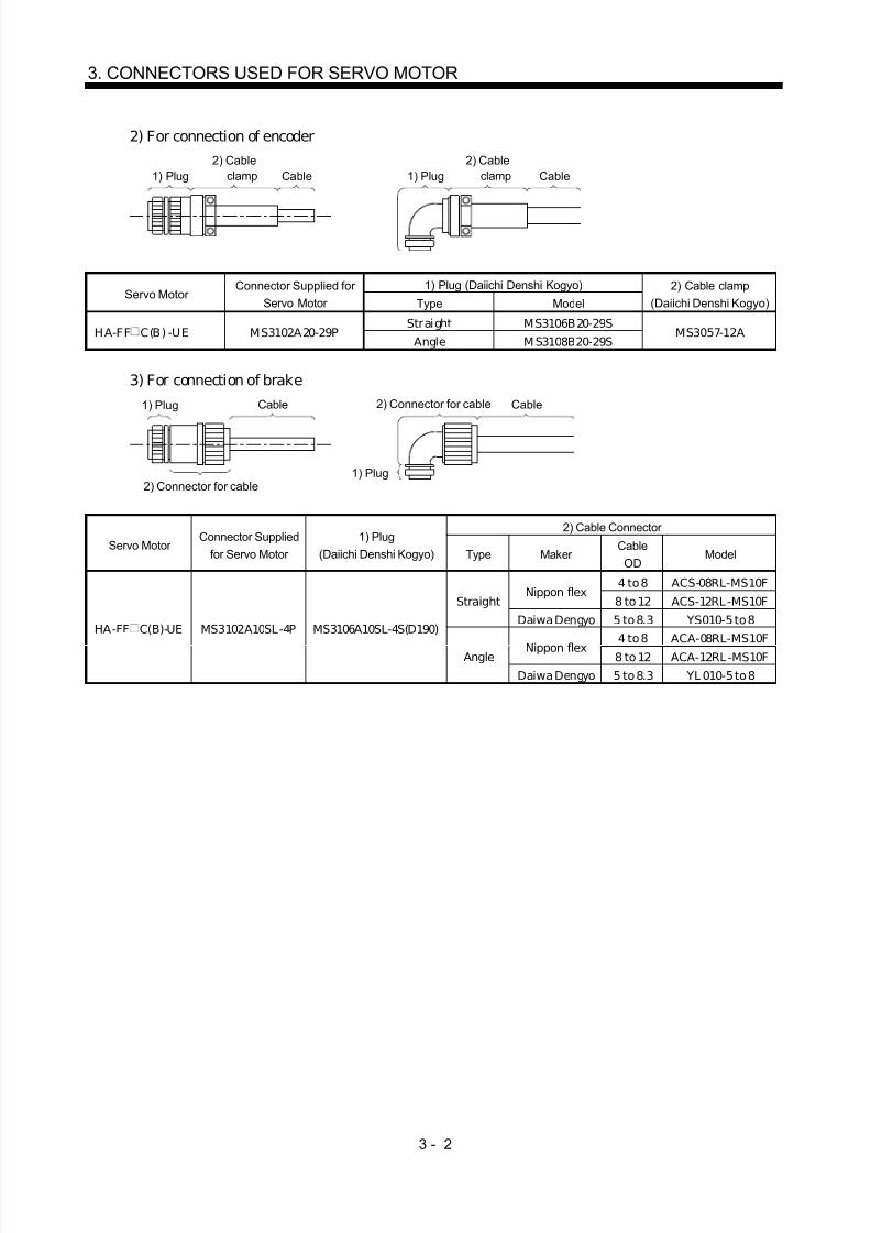
2) For connection of encoder
1) Plug2) Cable
clamp Cable 1) Plug2) Cable
clamp Cable
1) Plug (Daiichi Denshi Kogyo)Servo Motor
Connector Supplied for Servo Motor Type Model
2) Cable clamp(Daiichi Denshi Kogyo)
Straight MS3106B20-29SHA-FF C(B) -UE MS3102A20-29P
Angle M S3108B20-29SMS3057-12A
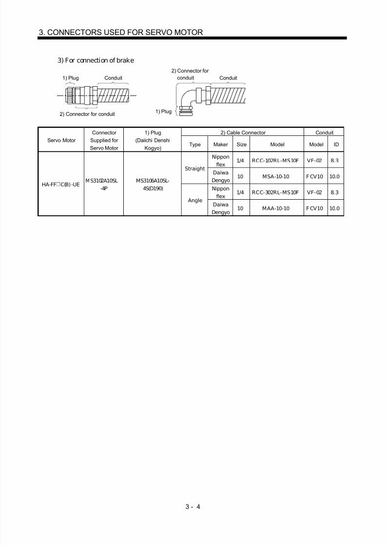
3) For connection of brake
1) Plug Cable
1) Plug
Cable2) Connector for cable
2) Connector for cable
2) Cable Connector
Servo Motor Connector Supplied
for Servo Motor 1) Plug
(Daiichi Denshi Kogyo) Type Maker Cable
ODModel
4 to 8 ACS-08RL-MS10FNippon flex
8 to 12 ACS-12RL-MS10FStraight
Daiwa Dengyo 5 to 8.3 YS010-5 to 8
4 to 8 ACA-08RL-MS10FNippon flex 8 to 12 ACA-12RL-MS10F
HA-FF C(B)-UE MS3102A10SL-4P MS3106A10SL-4S(D190)
Angle
Daiwa Dengyo 5 to 8.3 YL 010-5 to 8

8/10/2019 Servo Motor - Instruction Manual SH(NA)-3181-D (03.00)
http://slidepdf.com/reader/full/servo-motor-instruction-manual-shna-3181-d-0300 30/368
3 - 3
3. CONNECTORS USED FOR SERVO MOTOR
(b) When using flexible conduits1) For connection of power supply
1) Plug Conduit
1) Plug
2) Connector forconduit Conduit
2) Connector for conduit
2) Cable Connector ConduitServo Motor
Connector Supplied for Servo
Motor
1) Plug(Daiichi Denshi
Kogyo)Type Maker Size Model Model ID
1/4 RCC-102RL-MS14F VF-02 8.3
3/8 RCC-103RL-MS14F VF-03 10.6Nippon
flex1/2 RCC-104RL-MS14F VF-04 14.0
10 MSA-10-14 F CV10 10.0
Straight
DaiwaDengyo 12 MSA-12-14 F CV12 12.3
1/4 RCC-302RL-MS14F VF-02 8.3
3/8 RCC-303RL-MS14F VF-03 10.6Nippon
flex1/2 RCC-304RL-MS14F VF-04 14.0
10 MAA-10-14 F CV10 10.0
HA-FF C(B) -UE CE05-2A14S-2PD-B MS3106A14S-
2S(D190)
Angle
DaiwaDengyo 12 MAA-12-14 F CV12 12.3
2) For connection of encoder
1) Plug Conduit
1) Plug
2) Connector forconduit Conduit
2) Connector for conduit
2) Cable Connector ConduitServo Motor
Connector Supplied for Servo
Motor
1) Plug(Daiichi Denshi
Kogyo)Type Maker Size Model Model ID
1/2 RCC-104RL-MS20F VF-04 14.0Nipponflex 3/4 RCC-106RL-MS20F VF-06 19.0
16 MSA-16-20 F CV16 15.8Straight
DaiwaDengyo 22 MSA-22-20 F CV22 20.8
1/2 RCC-304RL-MS20F VF-04 14.0Nipponflex 3/4 RCC-306RL-MS20F VF-06 19.0
16 MAA-16-20 F CV16 15.8
HA-FF C(B) -UE MS3102A20-29P MS3106A20-
29S(D190)
AngleDaiwa
Dengyo 22 MAA-22-20 F CV22 20.8
8/10/2019 Servo Motor - Instruction Manual SH(NA)-3181-D (03.00)
http://slidepdf.com/reader/full/servo-motor-instruction-manual-shna-3181-d-0300 31/368
3 - 4
3. CONNECTORS USED FOR SERVO MOTOR
3) For connection of brake
1) Plug Conduit
1) Plug
2) Connector forconduit Conduit
2) Connector for conduit
2) Cable Connector ConduitServo Motor
Connector Supplied for Servo Motor
1) Plug(Daiichi Denshi
Kogyo)Type Maker Size Model Model ID
Nipponflex
1/4 RCC-102RL-MS10F VF-02 8.3Straight
DaiwaDengyo
10 MSA-10-10 F CV10 10.0
Nipponflex 1/4 RCC-302RL-MS10F VF-02 8.3
HA-FF C(B) -UE MS3102A10SL
-4PMS3106A10SL-
4S(D190)
AngleDaiwa
Dengyo 10 MAA-10-10 F CV10 10.0

8/10/2019 Servo Motor - Instruction Manual SH(NA)-3181-D (03.00)
http://slidepdf.com/reader/full/servo-motor-instruction-manual-shna-3181-d-0300 32/368
3 - 5
3. CONNECTORS USED FOR SERVO MOTOR
(2) EN Standard, UL/C-UL Standard-compliant(a) When using cabtyre cables
1) For connection of power supply
1) Plug Cable
1) Plug
Cable
2) Connector for
cable
2) Connector for cable
2) Connector for CableServo Motor
Connector Suppliedfor Servo Motor
1) Plug(Daiichi Denshi Kogyo) Maker Type Cable OD Model
4 to 8 ACS-08RL-MS14FStraight
8 to 12 ACS-12RL-MS14F
4 to 8 ACA-08RL-MS14FNippon
flexAngle
8 to 12 ACA-12RL-MS14F5 to 8.3 YSO14-5 to 8
Straight8.3 to 11.3 YSO14-9 to 11
5 to 8.3 YLO14-5 to 8
HA-FF C(B) -UE CE05-2A14S-2PD-B CE05-6A14S-2SD-B
DaiwaDengyo
Angle8.3 to 11.3 YL O14-9 to 11
2) For connection of encoder
1) Plug3) Cable
clamp Cable 2) Back shell
3) Cable clamp
Cable
2) Back shell1) Plug
2) Back Shell(Daiichi Denshi Kogyo)
3) Cable Clamp(Daiichi Denshi Kogyo)Servo Motor
Connector Supplied for Servo
Motor
1) Plug(Daiichi Denshi Kogyo)
Type Model Cable OD Model
Straight CE02-20BS-SHA-FF C(B) -UE MS3102A20-29P MS3106A20-29S(D190)
Angle CE-20BA-S6.8 to 10 CE3057-12A-3

8/10/2019 Servo Motor - Instruction Manual SH(NA)-3181-D (03.00)
http://slidepdf.com/reader/full/servo-motor-instruction-manual-shna-3181-d-0300 33/368
3 - 6
3. CONNECTORS USED FOR SERVO MOTOR
3) For connection of brake
1) Plug Cable
1) Plug
Cable2) Connector for
cable
2) Connector for cable
2) Connector for CableServo Motor
Connector Supplied for Servo
Motor
1) Plug(Daiichi Denshi Kogyo) Type Maker Cable OD Model
4 to 8 ACS-08RL-MS10FNippon flex
8 to 12 ACS-12RL-MS10FStraight
Daiwa Dengyo 5 to 8.3 YSO-10-5 to 8
4 to 8 ACA-08RL-MS10FNippon flex
8 to 12 ACA-12RL-MS10F
HA-FF C(B) -UE MS3102A10SL-4P MS3106A10SL-
4S(D190)
AngleDaiwa Dengyo 5 to 8.3 YL O10-5 to 8

8/10/2019 Servo Motor - Instruction Manual SH(NA)-3181-D (03.00)
http://slidepdf.com/reader/full/servo-motor-instruction-manual-shna-3181-d-0300 34/368
3 - 7
3. CONNECTORS USED FOR SERVO MOTOR
(b) When using flexible conduits1) For connection of power supply
1) Plug Conduit
1) Plug
2) Connector for conduit Conduit
2) Connector for conduit
2) Cable Connector ConduitServo Motor
Connector Supplied for Servo
Motor
1) Plug(Daiichi Denshi
Kogyo)Type Maker Size Model Model ID
1/4 RCC-102RL-MS14F VF-02 8.3
3/8 RCC-103RL-MS14F VF-03 10.6Nippon
flex1/2 RCC-104RL-MS14F VF-04 14.0
10 MSA-10-14 F CV10 10.0
Straight
DaiwaDengyo 12 MSA-12-14 F CV12 12.3
1/4 RCC-302RL-MS14F VF-02 8.3
3/8 RCC-303RL-MS14F VF-03 10.6Nippon
flex1/2 RCC-304RL-MS14F VF-04 14.0
10 MAA-10-14 F CV10 10.0
HA-FF C(B) -UE CE05-2A14S-2PD-B CE 05-6A14S-
2SD-B
Angle
DaiwaDengyo 12 MAA-12-14 F CV12 12.3
2) For connection of encoder
1) Plug Conduit
1) Plug
2) Connector forconduit Conduit
2) Connector for conduit
2) Cable Connector ConduitServo Motor
Connector Supplied for Servo
Motor
1) Plug(Daiichi Denshi
Kogyo)Type Maker Size Model Model ID
1/2 RCC-104RL-MS20F VF-04 14.0Nipponflex 3/4 RCC-106RL-MS20F VF-06 19.0
16 MSA-16-20 F CV16 15.8Straight
DaiwaDengyo 22 MSA-22-20 F CV22 20.8
1/2 RCC-304RL-MS20F VF-04 14.0Nipponflex 3/4 RCC-306RL-MS20F VF-06 19.0
16 MAA-16-20 F CV16 15.8
HA-FF C(B) -UE MS3102A20-29P MS3106A20-
29S(D190)
AngleDaiwa
Dengyo 22 MAA-22-20 F CV22 20.8

8/10/2019 Servo Motor - Instruction Manual SH(NA)-3181-D (03.00)
http://slidepdf.com/reader/full/servo-motor-instruction-manual-shna-3181-d-0300 35/368
3 - 8
3. CONNECTORS USED FOR SERVO MOTOR
3) For connection of brake
1) Plug Conduit
1) Plug
2) Connector forconduit Conduit
2) Connector for conduit
2) Cable Connector ConduitServo Motor
Connector Supplied for Servo Motor
1) Plug(Daiichi Denshi
Kogyo)Type Maker Size Model Model ID
Nipponflex
1/4 RCC-102RL-
MS10F VF-02 8.3
StraightDaiwaDengyo
10 MSA-10-10 F CV10 10.0
Nipponflex 1/4 RCC-302RL-MS10F VF-02 8.3
HA-FF C(B) -UE MS3102A10SL-4P MS3106A10-SL-
4S(D190)
AngleDaiwaDengyo
10 MAA-10-10 F CV10 10.0

8/10/2019 Servo Motor - Instruction Manual SH(NA)-3181-D (03.00)
http://slidepdf.com/reader/full/servo-motor-instruction-manual-shna-3181-d-0300 36/368
3 - 9
3. CONNECTORS USED FOR SERVO MOTOR
3.1.3 HC-SF(S), HC-RF(S), HC-UF(S)2000r/min, HA-LH, HA-LF series
(1) Non-waterproof, UL/C-UL Standard-compliant(a) When using cabtyre cables
1) For connection of power supply
1) Plug2) Cable
clamp Cable 1) Plug2) Cable
clamp Cable
1) Plug (Daiichi Denshi Kogyo)Servo Motor Connector Supplied for Servo Motor
Type Model2) Cable clamp
(Daiichi Denshi Kogyo)
Straight MS3106B22-23SHC-SF81(B)HC-SFS81(B)HC-SF 52(B) to 152(B)HC-SF S52(B) to 152(B)HC-SF 53(B) to 153(B)HC-SF S53(B) to 153(B)HC-RF103(B) to 203(B)HC-RFS103(B) to 203(B)HC-UF72(B) • 152(B)HC-UFS72(B) • 152(B)
CE 05-2A22-23PD-BAngle MS3108B22-23S
MS3057-12A
Straight MS3106B24-10SHC-SF 121(B) to 301(B)HC-SF S121(B) to 301(B)HC-SF 202(B) to 502(B)HC-SF S202(B) • 352(B)HC-SF 203(B) • 353(B)HC-SF S203(B) • 353(B)
HC-SF S353(B) to 503(B)HC-UF202(B) to 502(B)HC-UFS202(B)
CE 05-2A24-10PD-BAngle MS3108B24-10S
MS3057-16A
Straight MS3106B32-17SHC-SF 702(B) CE 05-2A32-17PD-B
Angle MS3108B32-17S M S3057-20A
2) For connection of encoder
1) Plug2) Cable
clamp Cable 1) Plug2) Cable
clamp Cable
1) Plug (Daiichi Denshi Kogyo)Servo Motor
Connector Supplied for Servo Motor Type Model
2) Cable clamp(Daiichi Denshi Kogyo)
Straight MS3106B20-29SHC-SF 81(B) to 301(B)HC-SF S81(B) to 301(B)HC-SF 52(B) to 702(B)HC-SF S52(B) to 352(B)HC-SF 53(B) to 353(B)HC-SF S53(B) to 353(B)HC-RF103(B) to 503(B)HC-RFS103(B) to 203(B)HC-UF72(B) to 502(B)HC-UFS72(B) to 202(B)HA-LH 11K2(B) to HA-LH 22K2(B)HA-LF 30K24(B) to HA-LF55K24(B)HA-LF30K2(B)
MS3102A20-29PAngle MS3108B20-29S
M S3057-12A

8/10/2019 Servo Motor - Instruction Manual SH(NA)-3181-D (03.00)
http://slidepdf.com/reader/full/servo-motor-instruction-manual-shna-3181-d-0300 37/368
3 - 10
3. CONNECTORS USED FOR SERVO MOTOR
3) For connection of brake
1) Plug Cable
1) Plug
Cable2) Connector for cable
2) Connector for cable
2) Connector for Cable
Servo Motor Connector
Supplied for ServoMotor
1) Plug(Daiichi Denshi
Kogyo)Type Maker
CableOD
Model
4 to 8 ACS-08RL -MS10FStraight
Nipponflex 8 to 12 ACS-12RL -MS10F
Angle Daiwa
Dengyo 5 to 8.3 YSO10-5 to 8
4 to 8 ACA-08RL -MS10FStraight
Nippon
flex 8 to 12 ACA-12RL -MS10F
HC-SF 121(B) to 301(B)HC-SF S121(B) to 301(B)HC-SF 202(B) to 502(B)HC-SF S202(B) • 352(B)HC-SF 203(B) • 353(B)
HC-SF S203(B) • 353(B)HC-UF202(B) • 502(B)HC-UF202(B)
MS3102A10SL-4P MS3106A10SL-4S
Angle Daiwa
Dengyo 5 to 8.3 YL O10-5 to 8

8/10/2019 Servo Motor - Instruction Manual SH(NA)-3181-D (03.00)
http://slidepdf.com/reader/full/servo-motor-instruction-manual-shna-3181-d-0300 38/368
3 - 11
3. CONNECTORS USED FOR SERVO MOTOR
(b) When using flexible conduits1) For connection of power supply
1) Plug Conduit
1) Plug
2) Connector forconduit Conduit
2) Connector for conduit
2) Connector for conduit ConduitServo Motor
Connector Supplied for Servo Motor
1) Plug(Daiichi
Denshi Kogyo)Type Maker Size Model Model ID
1/2 RCC-104RL-MS22F VF-04 14.0
3/4 RCC-106RL-MS22F VF-06 19.0Nippon
flex1 RCC-108RL-MS22F VF-08 24.4
16 M SA-16-22 F CV16 15.822 M SA-22-22 F CV22 20.8
Straight
DaiwaDengyo
28 M SA-28-22 F CV28 26.4
1/2 RCC-304RL-MS22F VF-04 14.0
3/4 RCC-306RL-MS22F VF-06 19.0Nippon
flex1 RCC-308RL-MS22F VF-08 24.4
16 MAA-16-22 F CV16 15.8
22 MAA-22-22 F CV22 20.8
HC-SF81(B)HC-SFS81(B)
HC-SF 52(B) to 152(B)HC-SF S52(B) to 152(B)HC-SF 53(B) to 153(B)HC-SF S53(B) to 153(B)HC-RF103(B) to 203(B)HC-RFS103(B) to 203(B)HC-UF72(B) • 152(B)HC-UFS72(B) • 152(B)
CE05-2A22-23PD-B
MS3106A22-23S(D190)
Angle
DaiwaDengyo
28 MAA-28-22 F CV28 26.4
1/2 RCC-104RL-MS24F VF-04 14.0
3/4 RCC-106RL-MS24F VF-06 19.0Nippon
flex1 RCC-108RL-MS24F VF-08 24.4
16 M SA-16-24 F CV16 15.822 M SA-22-24 F CV22 20.8
StraightDaiwaDengyo
28 M SA-28-24 F CV28 26.4
1/2 RCC-304RL-MS24F VF-04 14.0
3/4 RCC-306RL-MS24F VF-06 19.0Nippon
flex1 RCC-308RL-MS24F VF-08 24.4
16 MAA-16-24 F CV16 15.8
22 MAA-22-24 F CV22 20.8
HC-SF 121(B) to 301(B)
HC-SF S121(B) to 301(B)HC-SF 202(B) to 502(B)HC-SF S202(B) • 352(B)HC-SF 203(B) • 353(B)HC-SF S203(B) • 353(B)HC-RF353(B) to 503(B)HC-UF202(B) • 502(B)HC-UF202(B)
CE05-2A24-10PD-B
MS3106A24-10S(D190)
Angle
DaiwaDengyo
28 MAA-28-24 F CV28 26.4
3/4 RCC-106RL-MS32F VF-06 19.0Straight
Nipponflex 1 RCC-108RL-MS32F VF-08 24.4
3/4 RCC-306RL-MS32F VF-06 19.0HC-SF702(B)
CE05-2A32-17PD-B
MS3106A32-17S(D190)
Angle Daiwa
Dengyo 1 RCC-308RL-MS32F VF-08 24.4
8/10/2019 Servo Motor - Instruction Manual SH(NA)-3181-D (03.00)
http://slidepdf.com/reader/full/servo-motor-instruction-manual-shna-3181-d-0300 39/368
3 - 12
3. CONNECTORS USED FOR SERVO MOTOR
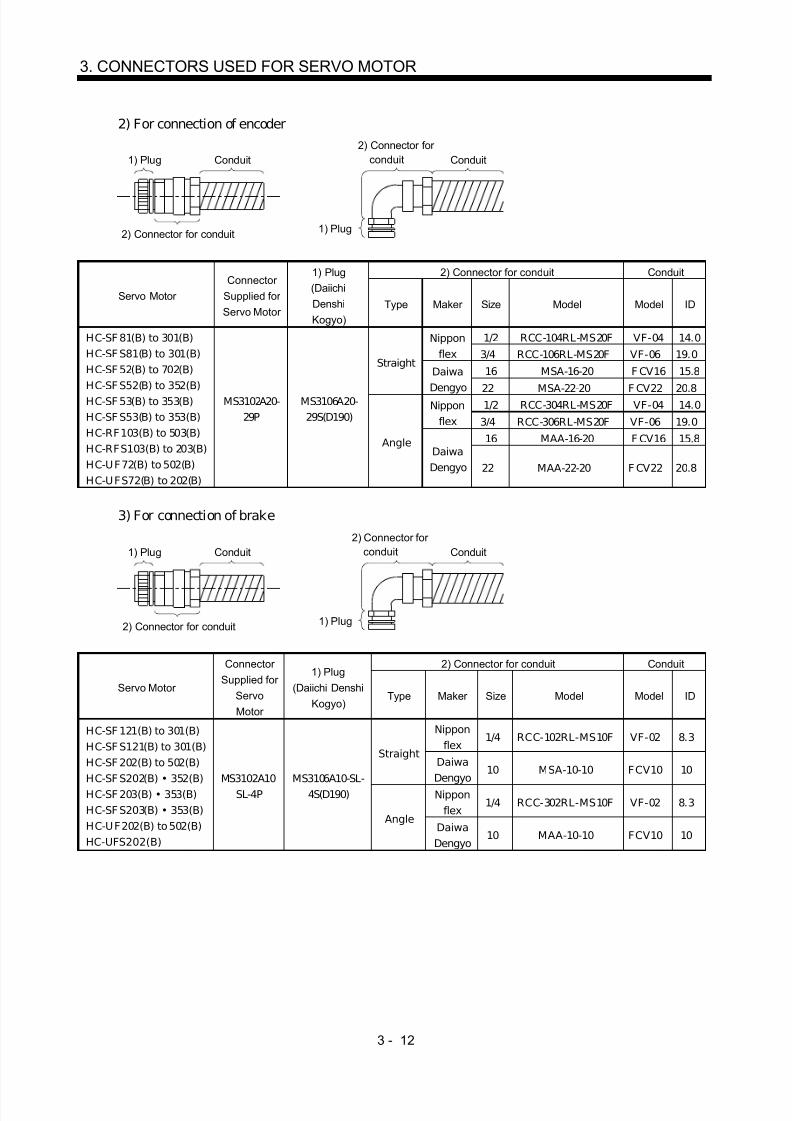
2) For connection of encoder
1) Plug Conduit
1) Plug
2) Connector forconduit Conduit
2) Connector for conduit
2) Connector for conduit Conduit
Servo Motor Connector
Supplied for Servo Motor
1) Plug(DaiichiDenshiKogyo)
Type Maker Size Model Model ID
1/2 RCC-104RL-MS20F VF-04 14.0Nipponflex 3/4 RCC-106RL-MS20F VF-06 19.0
16 MSA-16-20 F CV16 15.8Straight
Daiwa
Dengyo 22 MSA-22-20 F CV22 20.81/2 RCC-304RL-MS20F VF-04 14.0Nippon
flex 3/4 RCC-306RL-MS20F VF-06 19.0
16 MAA-16-20 F CV16 15.8
HC-SF 81(B) to 301(B)HC-SF S81(B) to 301(B)HC-SF 52(B) to 702(B)HC-SF S52(B) to 352(B)HC-SF 53(B) to 353(B)HC-SF S53(B) to 353(B)HC-RF103(B) to 503(B)HC-RFS103(B) to 203(B)HC-UF72(B) to 502(B)HC-UFS72(B) to 202(B)
MS3102A20-29P
MS3106A20-29S(D190)
AngleDaiwaDengyo 22 MAA-22-20 F CV22 20.8
3) For connection of brake
1) Plug Conduit
1) Plug
2) Connector forconduit Conduit
2) Connector for conduit
2) Connector for conduit Conduit
Servo Motor
Connector Supplied for
ServoMotor
1) Plug(Daiichi Denshi
Kogyo)Type Maker Size Model Model ID
Nipponflex
1/4 RCC-102RL-MS10F VF-02 8.3Straight
DaiwaDengyo
10 MSA-10-10 FCV10 10
Nipponflex
1/4 RCC-302RL-MS10F VF-02 8.3
HC-SF 121(B) to 301(B)HC-SF S121(B) to 301(B)HC-SF 202(B) to 502(B)HC-SF S202(B) • 352(B)HC-SF 203(B) • 353(B)HC-SF S203(B) • 353(B)HC-UF202(B) to 502(B)HC-UFS202(B)
MS3102A10SL-4P
MS3106A10-SL-4S(D190)
AngleDaiwa
Dengyo 10 MAA-10-10 FCV10 10

8/10/2019 Servo Motor - Instruction Manual SH(NA)-3181-D (03.00)
http://slidepdf.com/reader/full/servo-motor-instruction-manual-shna-3181-d-0300 40/368
3 - 13
3. CONNECTORS USED FOR SERVO MOTOR
(2) Waterproof (IP65), EN Standard, UL/C-UL Standard-compliant(a) When using cabtyre cables
1) For connection of power supply
1) Plug
2) Cable
clamp Cable 1) Plug
2) Cable
clamp Cable
1) Plug (Daiichi Denshi Kogyo)2) Cable clamp
(Daiichi Denshi Kogyo)Servo Motor Connector
Supplied for Servo Motor Type Model Cable OD Model
Straight CE05-6A22-23SD-B-BSS 9.5 to 13 CE3057-12A-2(D265)HC-SF81(B)HC-SFS81(B)HC-SF 52(B) to 152(B)HC-SF S52(B) to 152(B)
HC-SF 53(B) to 153(B)HC-SF S53(B) to 153(B)HC-RF103(B) to 203(B)HC-RFS103(B) to 203(B)HC-UF72(B) • 152(B)HC-UFS72(B) • 152(B)
CE 05-2A22-23PD-B Angle CE05-8A22-23SD-B-BAS 12.5 to 16 CE3057-12A-1(D265)
Straight CE05-6A24-10SD-B-BSS 13 to 15.5 CE3057-16A-2(D265)HC-SF 121(B) to 301(B)HC-SF S121(B) to 301(B)HC-SF 202(B) to 502(B)HC-SF S202(B) • 352(B)HC-SF 203(B) • 353(B)HC-SF S203(B) • 353(B)HC-RF353(B) to 503(B)HC-UF202(B) to 502(B)HC-UFS202(B)
CE 05-2A24-10PD-B Angle CE05-8A24-10SD-B-BAS 15 to 19.1 CE3057-16A-1(D265)
Straight CE05-6A32-17SD-B-BSS 22 to 23.8 CE3057-20A-1(D265)HC-SF702(B)
CE 05-2A32-17PD-B Angle CE05-8A32-17SD-B-BAS 22 to 23.8 CE3057-20A-1(D265)
2) For connection of encoder
1) Plug3) Cable
clamp Cable 2) Back shell
3) Cable clamp
Cable
2) Back shell1) Plug
2) Back shell3) Cable clamp
(Daiichi Denshi Kogyo)Servo Motor Connector
Supplied for Servo Motor
1) Plug(Daiichi Denshi
Kogyo) Type Model Cable OD Model
Straight CE02-20BS-SHC-SF 81(B) to 301(B)HC-SF S81(B) to 301(B)HC-SF 52(B) to 702(B)HC-SF S52(B) to 352(B)HC-SF 53(B) to 353(B)HC-SF S53(B) to 353(B)HC-RF103(B) to 503(B)HC-RFS103(B) to 203(B)HC-UF72(B) to 502(B)
HC-UFS72(B) to 202(B)
MS3102A20-29P
MS3106A20-29S(D190) Angle CE-20BA-S
6.8 to 10 CE3057-12A-3(D265)

8/10/2019 Servo Motor - Instruction Manual SH(NA)-3181-D (03.00)
http://slidepdf.com/reader/full/servo-motor-instruction-manual-shna-3181-d-0300 41/368
3 - 14
3. CONNECTORS USED FOR SERVO MOTOR
3) For connection of brake
1) Plug Cable
1) Plug
Cable2) Connector for
cable
2) Connector for cable
2) Connector for CableServo Motor
Connector Suppliedfor Servo Motor
1) Plug(Daiichi Denshi Kogyo) Type Maker
CableOD
Model
4 to 8 ACS-08RL -MS10FNipponflex 8 to 12 ACS-12RL -MS10F
StraightDaiwaDengyo
5 to 8.3 YSO-10-5 to 8
4 to 8 ACA-08RL -MS10FNipponflex 8 to 12 ACA-12RL -MS10F
HC-SF 121(B) to 301(B)HC-SF S121(B) to 301(B)HC-SF 202(B) to 502(B)HC-SF S202(B) • 352(B)
HC-SF 203(B) • 353(B)HC-SF S203(B) • 353(B)HC-UF202(B) to 502(B)HC-UFS202(B)
MS3102A10SL-4P MS3106A10SL-
4S(D190)
AngleDaiwaDengyo
5 to 8.3 YL O-10-5 to 8

8/10/2019 Servo Motor - Instruction Manual SH(NA)-3181-D (03.00)
http://slidepdf.com/reader/full/servo-motor-instruction-manual-shna-3181-d-0300 42/368
3 - 15
3. CONNECTORS USED FOR SERVO MOTOR
(b) When using flexible conduits1) For connection of power supply
1) Plug Conduit
1) Plug
2) Connector for conduit Conduit
2) Connector for conduit
2) Connector for conduit ConduitServo Motor
Connector Supplied for Servo Motor
1) Plug(Daiichi Denshi
Kogyo)Type Maker Size Model Model ID
1/2 RCC-104RL-MS22F VF-04 14.0
3/4 RCC-106RL-MS22F VF-06 19.0Nippon
flex1 RCC-108RL-MS22F VF-08 24.4
16 M SA-16-22 F CV16 15.822 M SA-22-22 F CV22 20.8
Straight
DaiwaDengyo
28 M SA-28-22 F CV28 26.4
1/2 RCC-304RL-MS22F VF-04 14.0
3/4 RCC-306RL-MS22F VF-06 19.0Nippon
flex1 RCC-308RL-MS22F VF-08 24.4
16 M AA-16-22 F CV16 15.8
22 M AA-22-22 F CV22 20.8
HC-SF81(B)HC-SFS81(B)
HC-SF 52(B) to 152(B)HC-SF S52(B) to 152(B)HC-SF 53(B) to 153(B)HC-SF S53(B) to 153(B)HC-RF103(B) to 203(B)HC-RFS103(B) to 203(B)HC-UF72(B) • 152(B)HC-UFS72(B) • 152(B)
CE05-2A22-23PD-B
CE05-6A22-23SD-B
Angle
DaiwaDengyo
28 M AA-28-22 F CV28 26.4
1/2 RCC-104RL-MS24F VF-04 14.0
3/4 RCC-106RL-MS24F VF-06 19.0Nippon
flex1 RCC-108RL-MS24F VF-08 24.4
16 M SA-16-24 F CV16 15.822 M SA-22-24 F CV22 20.8
StraightDaiwaDengyo
28 M SA-28-24 F CV28 26.4
1/2 RCC-304RL-MS24F VF-04 14.0
3/4 RCC-306RL-MS24F VF-06 19.0Nippon
flex1 RCC-308RL-MS24F VF-08 24.4
16 M AA-16-24 F CV16 15.8
22 M AA-22-24 F CV22 20.8
HC-SF 121(B) to 301(B)
HC-SF S121(B) to 301(B)HC-SF 202(B) to 502(B)HC-SF S202(B) to 352(B)HC-SF 203(B) • 353(B)HC-SF S203(B) • 353(B)HC-RF353(B) to 503(B)HC-UF202(B) to 502(B)HC-UFS202(B)
CE05-2A24-
10PD-B
CE05-6A24-10SD-B
Angle
DaiwaDengyo
28 M AA-28-24 F CV28 26.4
3/4 RCC-106RL-MS32F VF-06 19.0Straight
Nipponflex 1 RCC-108RL-MS32F VF-08 24.4
3/4 RCC-306RL-MS32F VF-06 19.0HC-SF702(B)
CE05-2A32-
17PD-B
CE05-6A32-17SD-B
Angle Nippon
flex 1 RCC-308RL-MS32F VF-08 24.4

8/10/2019 Servo Motor - Instruction Manual SH(NA)-3181-D (03.00)
http://slidepdf.com/reader/full/servo-motor-instruction-manual-shna-3181-d-0300 43/368

8/10/2019 Servo Motor - Instruction Manual SH(NA)-3181-D (03.00)
http://slidepdf.com/reader/full/servo-motor-instruction-manual-shna-3181-d-0300 44/368
3 - 17
3. CONNECTORS USED FOR SERVO MOTOR
3.1.5 HC-KFS, HC-MFS, HC-UFS3000r/min series
Use the connectors indicated in thi s section or equivalent for connection of the power supply,electromagnetic brake and encoder. These connectors may be used for the EN Standard and UL/C-ULStandard but are not waterproof.
1) For connection of power supply and brake
Cable Side Connector Servo Motor
Servo Motor SideConnector (molex) Plug (molex) Terminal (molex)
HC-KFSHC-MFSHC-UFS13 to 73
5557-04R-210 5559-04P-210 5558PBTL
Cable Side Connector Servo Motor
Servo Motor SideConnector (molex) Plug (molex) Terminal (molex)
HC-KFS B
HC-MFS BHC-UFS13 to 73B
5557-06R-210 0009-06P-210 5558PBTL
2) For connection of encoder
Encoder Cable Connector Servo Motor
Servo Motor SideConnector (AMP) Housing (AMP) Connector pin (AMP)
Cable clamp(Toa Electric Industry)
HC-KF S (B)HC-MFS (B)HC-UFS13 to 73(B)
1-172169-9 1-172161-9 170363-1 MTI-0002

8/10/2019 Servo Motor - Instruction Manual SH(NA)-3181-D (03.00)
http://slidepdf.com/reader/full/servo-motor-instruction-manual-shna-3181-d-0300 45/368
3 - 18
3. CONNECTORS USED FOR SERVO MOTOR
3.2 IP65, EN Standard-Compliant Options
The following options are available to satisfy the IP65 ingress protection and EN Standard. To comply with the EN Standard, the power supply connector used must be any of these Options or
equivalent.Product Model Description Servo Motor
Servo amplifier side connector(3M make or equivalent)Connector: 10120-3000VEShell k it: 10320-52F0-008
Encoder side connector(DDK make)Plug: MS3106A20-29S(D190)Cable clamp: CE3057-12A-3(D265)Back shell: CE02-20BS-S
IP65-compliantencoder cable(MR-J 2 series)
MR-ENCBL M-H HC-SF seriesHC-RF seriesHC-UF2000r/minseriesHA-L F-UE seriesHA-F F-UE seriesHA-SFS seriesHA-RFS seriesHC-UFS2000r/minseries
Servo amplifier side connector(Honda Tsushin K ogyo make)Connector: PCR-S20FSCase: PCR-L S20LA1
Encoder side connector(DDK make)Plug: MS3106A20-29S(D190)Cable clamp: CE3057-12A-3(D265)Back shell: CE02-20BS-S
Encoder cable(MR-H- N series)
MR-EN1CBL M-H HC-SF seriesHC-RF seriesHC-UF2000r/minseriesHA-L F-UE series
Servo amplifier side connector(3M make or equivalent)Connector: 10120-3000VEShell k it: 10320-52F0-008
Encoder side connector(DDK make)Plug: MS3106A20-29S(D190)Cable clamp: CE3057-12A-3(D265)Back shell: CE02-20BS-S
Encoderconnector set(MR-J 2 series)
MR-ENCNS HC-SF seriesHC-RF seriesHC-UF2000r/minseriesHC-SFS seriesHC-RFS seriesHC-UFS2000r/minseries
Servo amplifier side connector(Honda Tsushin K ogyo make)Connector: PCR-S20FSCase: PCR-L S20LA1
Encoder side connector(DDK make)Plug: MS3106A20-29S(D190)Cable clamp: CE3057-12A-3(D265)Back shell: CE02-20BS-S
Encoderconnector set(MR-H- N series)
MR-EN1CNS HC-SF seriesHC-RF seriesHC-UF2000r/minseriesHA-LF series
EN Standard-
compliant powerconnector set
MR-PWCNF Plug: CE05-6A14S-2SD-B (Daiichi Denshi Kogyo make)
Cable connector: YSO14-9 to 11 (Daiwa Dengyo make)
HA-FF C-UE
series

8/10/2019 Servo Motor - Instruction Manual SH(NA)-3181-D (03.00)
http://slidepdf.com/reader/full/servo-motor-instruction-manual-shna-3181-d-0300 46/368
3 - 19
3. CONNECTORS USED FOR SERVO MOTOR
Product Model Description Servo Motor
IP65/ENStandard-compliant powerconnector set
MR-PWCNS1 Plug: CE05-6A22-23SD-B-BSSCable clamp: CE3057-12A-2 (D265) (DDK make)
HC-SF81(B)HC-SF52(B) to 152(B)HC-SF53(B) to 153(B)HC-RF 103(B) to 203(B)HC-UF72(B) •152(B)HC-SFS81(B)HC-SFS52(B) to 152(B)HC-SFS53(B) to 153(B)HC-RF S103(B) to 203(B)HC-UFS72(B) •152(B)
IP65/ENStandard-compliant powerconnector set
MR-PWCNS2 Plug: CE05-6A22-10SD-B-BSSCable clamp: CE3057-16A-2 (D265) (DDK make)
HC-SF 121(B) to 301(B)HC-SF 202(B) to 502(B)HC-SF203(B) • 353(B)HC-RF 353(B) • 503(B)HC-UF202(B) to 502(B)HC-SFS121(B) to 301(B)HC-SFS202(B) to 352(B)HC-SFS203(B) • 353(B)HC-RFS353(B)HC-UFS202(B) • 352(B)
Power connectorset
MR-PWCNS3 Plug:CE05-6A32-17SD-B-BSSCable clamp: CE3057-20A-1 (D265) (DDK make)
HC-SF702(B)
IP65/ENStandard-compliant brakeconnector set
MR-BKCN (Note) Plug: MS3106A10SL-4S(D190) (DDK make)Cable connector: YSO10-5 to 8 (Daiwa Dengyomake)
HA-FF CB-UEHC-SF121B to 301BHC-SF202B to 502BHC-SF203B • 353BHC-UF202B • 502B
HC-SFS121B to 301BHC-SFS202B to 352BHC-SFS203B • 353BHC-UF S202B
Note: If it i s used with the HA-FF C-U E, the servo motor does not improve in ingress protection (IP54).

8/10/2019 Servo Motor - Instruction Manual SH(NA)-3181-D (03.00)
http://slidepdf.com/reader/full/servo-motor-instruction-manual-shna-3181-d-0300 47/368
3 - 20
3. CONNECTORS USED FOR SERVO MOTOR
3.3 Signal Arrangement of Encoder Connectors
The encoder connector of each servo motor has the following signal arrangement. The connectors shownare as seen from the pin side.
Servo Motor Series Signal ArrangementHC-KF(-UE) seriesHC-MF(-UE) seriesHA-FF seriesHC-UF3000r/min seriesHC-K FS seriesHC-M FS seriesHC-UFS3000r/min series
Encoder connectors1-172169-9 (AMP make)
1 2 3
4 5 6
7 8 9
MR MRR BAT
MD MDR CNT
P5 LG SHD
HA-FF C-UE seriesHC-SF series
HC-RF seriesHC-UF2000r/min seriesHA-LH seriesHA-LF seriesHC-SFS seriesHC-RF S seriesHC-UFS2000r/min series
A BC
D
E
FGH
J
KL
M
Pin Signal A
BC MRD MRREF BATG LGHJ
Pin SignalK
LMN SHDPR LGS P5T
Encoder connectors
RS
T PN MDR
MD
CNT
HC-AQ series
12 6
11 5
10 4
MRR MR
LG P5
SHD
9 3
8 2
7 1
W U
V E
B1 B2
Motor connector

8/10/2019 Servo Motor - Instruction Manual SH(NA)-3181-D (03.00)
http://slidepdf.com/reader/full/servo-motor-instruction-manual-shna-3181-d-0300 48/368
4 - 1
4. INSPECTION
4. INSPECTION
WARNING
Before starting maintenance and/or inspection, make sure that the charge lamp isoff more than 10 minutes after power-off. Then, confirm that the voltage is safe in
the tester or the like. Otherwise, you may get an electric shock. Any person who is involved in inspection should be fully competent to do the work.Otherwise, you may get an electric shock. For repair and parts replacement,contact your safes representative.
POINTDo not disassemble and/or repair the equipment on customer side.
(1) I nspection
It is recommended to make the following checks periodically:(a) Check the servo motor bearings, brake section, etc. for unusual noise.
(b) Check the cables and the like for scratches and cracks. Perform periodic inspection according tooperating conditions.
(c) Check the servo motor shaft and coupling for misalignment.
(2) Life The following parts must be changed periodically as listed below. If any part is found faulty, it must bechanged immediately even when it has not yet reached the end of its life, which depends on theoperating method and environmental conditions. For parts replacement, please contact your sales
representative.Part Name Guideline of Life Remarks
Bear ings 20,000 to 30,000 hours
Encoder 20,000 to 30,000 hours
Oil seal, V ring 5,000 hours
Cooling fan 20,000 hours
If the servo motor is used in atmosphere where there are muchoil mist, dust, etc., clean and check the parts every threemonths.
(a) BearingsWhen the servo motor is run at rated speed under rated load, change the bearings in 20,000 to30,000 hours as a guideline. This differs on the operating conditions. The bearings must also bechanged if unusual noise or vibration is found during inspection.
(b) Oil seal, V ringMust be changed in 5,000 hours of operation at rated speed as a guideline. This differs on theoperating conditions. These parts must also be changed if oil leakage, etc. is found duringinspection.

8/10/2019 Servo Motor - Instruction Manual SH(NA)-3181-D (03.00)
http://slidepdf.com/reader/full/servo-motor-instruction-manual-shna-3181-d-0300 49/368
4 - 2
4. INSPECTION
MEMO

8/10/2019 Servo Motor - Instruction Manual SH(NA)-3181-D (03.00)
http://slidepdf.com/reader/full/servo-motor-instruction-manual-shna-3181-d-0300 50/368
5 - 1
5. SPECIFICATIONS
5. SPECIFICATIONS
5.1 Standard Specifications
HC-MF Series(Ultra low inertia, small capacity)
HA-FF Series(Low inertia, small capacity)
Servo Motor
Item 053 13 23 43 73 053 13 23 33 43 63MR-H AN/BN/ACN/TN 20 20 40 60 100 10 10 20 40 40 60Applicable servo
amplifier MR-J 2- A/B/C 10 10 20 40 70 10 10 20 40 40 60Rated output [kW] 0.05 0.1 0.2 0.4 0.75 0.05 0.1 0.2 0.3 0.4 0.6
[N ⋅ m] 0.16 0.32 0.64 1.3 2.4 0.16 0.32 0.64 0.95 1.3 1.9(Note 1,11)Continuousduty
Ratedtorque [oz ⋅ i n] 22.7 45.3 90.7 184 340 22.7 45.3 90.7 135 184 269
(Note 1) Rated speed [r/min] 3000 3000Maximum speed [r/min] 4500 4000Permissible instantaneous speed [r/min] 5175 4600
[N ⋅ m] 0.48 0.95 1.9 3.8 7.2 0.48 0.95 1.9 2.9 3.8 5.7Maximum torque
[oz ⋅ in] 68.0 135 269 538 1020 68.0 135 269 411 538 808Power rate at continuous rated torque
[kW/s] 13.47 34.13 46.02 116.55 94.43 4.0 10.2 11.7 18.1 17.2 30.1
J [ 10 -4kg ⋅ m 2] 0.019 0.03 0.088 0.143 0.6 0.063 0.10 0.35 0.50 0.98 1.2(Note 3)Inertia moment WK 2 [oz ⋅ in 2] 0.104 0.16 0.48 0.78 3.28 0.344 0.55 1.91 2.73 5.36 6.56(Note 2) Recommended ratio of load inertiamoment to servo motor shaft inertia moment 30 times or less 10 times or less
Servo amplifier' built-inregenerative brakeresistor
(Note 5) (Note 5) (Note 5) 4275 1726 (Note 5) (Note 5) (Note 5) 1500 750 600
MR-RB013(10W) (Note 5) (Note 5) 2071 1363 370
MR-RB033(30W) (Note 5) (Note 5) (Note 5) 4088 1109
MR-RB31(300W)MR-RB32(300W) (Note 5) (Note 5) (Note 5) (Note 5) 3983 3046
MR-RB30(300W)MR-RB34(300W)MR-RB50(500W)MR-RB51(500W)MR-RB54(500W)MR-RB65(600W)MR-RB66(600W)
MR-Hseries
MR-RB67(600W)Servo amplifier' built-inregenerative brakeresistor
(Note 5) (Note 5) (Note 5) 1010 400 (Note 5) (Note 5) (Note 5) 320 150 120
MR-RB032(30W) 3000 600 950 450 360
MR-RB12(100W) (Note 5) 2400 3200 1500 1200
MR-RB32(300W)MR-RB30(300W)
(Note4)Regenerative brakeduty[times/min]
MR-J 2series
MR-RB50(500W)
Power supply capacity Refer to ″ Power supply equipment capacity and generated loss of servo amplifiers"
in Servo Amplifier Instruction Manual.Rated current [A] 0.85 0.85 1.5 2.8 5.1 0.6 1.1 1.3 1.9 2.5 3.6Maximum current [A] 2.6 2.6 5 9 18 1.8 3.3 3.9 5.7 7.5 10.8Speed/position detector Encoder (resolution : 8192 pulse/rev) Encoder (resolution : 8192 pulse/rev)Accessories Encoder Encoder, V ringInsulation class Class B Class B
Structure Totally-enclosed, self-cooled
(protection type: IP44 (Note 6,12)) Totally-enclosed, self-cooled
(protection type: IP44 (Note 8,9,12))(Note 7) Environmental condi tions Refer to section 2.1 Refer to section 2.1
[kg] 0.4 0.53 0.99 1.45 3.0 1.3 1.5 2.3 2.6 4.2 4.8(Note 3) Weight
[lb] 0.88 1.17 2.18 3.20 6.61 2.87 3.31 5.07 5.73 9.26 10.6
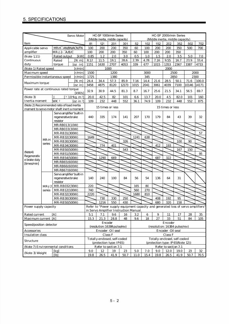
8/10/2019 Servo Motor - Instruction Manual SH(NA)-3181-D (03.00)
http://slidepdf.com/reader/full/servo-motor-instruction-manual-shna-3181-d-0300 51/368
5 - 2
5. SPECIFICATIONS
HC-SF 1000r/min Series(Middle inertia, middle capacity)
HC-SF 2000r/min Series(Middle inertia, middle capacity)
Servo Motor
Item 81 121 201 301 52 102 152 202 352 502 702MR-H AN/BN/ACN/TN 100 200 200 350 60 100 200 200 350 500 700Applicable servo
amplifier MR-J 2- A/B/C 100 200 200 350 60 100 200 200 350
Rated output [kW] 0.85 1.2 2.0 3.0 0.5 1.0 1.5 2.0 3.5 5.0 7.0[N ⋅ m] 8.12 11.5 19.1 28.6 2.39 4.78 7.16 9.55 16.7 23.9 33.4
(Note 1,11)Continuousduty
Ratedtorque [oz ⋅ in] 1151 1630 2707 4053 339 677 1015 1353 2367 3387 4733
(Note 1) Rated speed [r/min] 1000 2000Maximum speed [r/min] 1500 1200 3000 2500 2000Permissible instantaneous speed [r/min] 1725 1380 345 2850 2300
[N ⋅ m] 24.4 34.4 57.3 85.9 7.16 14.4 21.6 28.5 50.1 71.6 100.0Maximum torque
[oz ⋅ in] 3458 4875 8120 12173 1015 2041 3061 4039 7100 10146 14171Power rate at continuous rated torque
[kW/s] 32.9 30.9 44.5 81.3 8.7 16.7 25.6 21.5 34.1 56.5 69.7
J [ 10-4kg ⋅ m 2] 20.0 42.5 82 101 6.6 13.7 20.0 4.5 82.0 101 160(Note 3)Inertia moment WK 2 [oz ⋅ in 2] 109 232 448 552 36.1 74.9 109 232 448 552 875(Note 2) Recommended ratio of load inertiamoment to servo motor shaft inertia moment 15 times or less 15 times or less
Servo amplifier' built-inregenerative brakeresistor
440 335 174 141 207 170 179 84 43 39 32
MR-RB013(10W)MR-RB033(30W)MR-RB31(300W) 57MR-RB32(300W) 1649 1241 638MR-RB30(300W) 326 100 90MR-RB34(300W) 774 401 412 193MR-RB50(500W) 543 167 150MR-RB51(500W) 95MR-RB54(500W) 1290 669 687 322MR-RB65(600W)MR-RB66(600W)
MR-Hseries
MR-RB67(600W)Servo amplifier' built-inregenerative brakeresistor
140 240 100 84 56 54 136 64 31
MR-RB032(30W) 220 165 80MR-RB12(100W) 740 560 270MR-RB32(300W) 2220 1680 810MR-RB30(300W) 730 330 250 408 192 95
(Note4)Regenerative brake duty[times/min]
MR-J 2series
MR-RB50(500W) 1216 550 430 680 320 158Power supply capacity Refer to "Power supply equipment capacity and generated loss of servo amplifiers"
in Servo Amplifier Instruction Manual.Rated current [A] 5.1 7.1 9.6 16 3.2 6 9 11 17 28 35Maximum current [A] 15.3 21.3 28.8 48 9.6 18 27 33 51 84 105
Speed/position detector Encoder
(resolution: 16384 pulse/rev)
Encoder
(resolution: 16384 pulse/rev)Accessories Encoder Oil seal Encoder Oil sealInsulation class Class F Class F
Structure Totally-enclosed, self-cooled
(protection type: IP65) Totally-enclosed, self-cooled
(protection type: IP 65(Note 12))(Note 7) Environmental condi tions Refer to section 2.1 Refer to section 2.1
[kg] 9.0 12 19 23 5.0 7.0 9.0 12.0 19.0 23 32(Note 3) Weight
[lb] 19.8 26.5 41.9 50.7 11.0 15.4 19.8 26.5 41.9 50.7 70.5

8/10/2019 Servo Motor - Instruction Manual SH(NA)-3181-D (03.00)
http://slidepdf.com/reader/full/servo-motor-instruction-manual-shna-3181-d-0300 52/368
5 - 3
5. SPECIFICATIONS
HC-SF 3000r/min Series(Middle inertia, middle capacity)
HC-RF Series(Low inertia, small capacity)Servo Motor
Item 53 103 153 203(Note 13)
353103 153 203 353 503
MR-H AN/BN/ACN/TN 60 100 200 200 350 200 200 350 500 500Applicable servo
amplifier MR-J 2- A/B/C 60 100 200 200 350 200 200 350Rated output [kW] 0.5 1.0 1.5 2.0 3.5 1.0 1.5 2.0 3.5 5.0[N ⋅ m] 1.59 3.18 4.78 6.37 11.1 3.18 4.78 6.37 11.1 15.9
(Note 1,11)Continuousduty
Ratedtorque [oz ⋅ in] 225 451 677 903 1573 451 677 903 1573 2253
(Note 1) Rated speed [r/min] 3000 3000Maximum speed [r/min] 3000 4500Permissible instantaneous speed [r/min] 3450 5175
[N ⋅ m] 4.77 9.55 14.3 19.1 33.4 7.95 11.9 15.9 27.9 39.7Maximum torque
[oz ⋅ in] 676 1353 2026 2707 4733 1127 1686 2253 3954 5626Power rate at continuous rated torque
[kW/s] 3.8 7.4 11.4 9.5 15.1 67.4 120 176 150 211
J [ 10-4kg ⋅ m 2] 6.6 13.7 20.0 42.5 82.0 1.5 1.9 2.3 8.6 12.0(Note 3)Inertia moment WK 2 [oz ⋅ in 2] 36.1 74.9 109.3 232.4 448.3 8.2 10.4 12.6 47.0 65.6(Note 2) Recommended ratio of load inertia
moment to servo motor shaft inertia moment 15 times or less 5 times or less
Servo amplifier' built-inregenerative brakeresistor
92 71 79 37 19 1056 834 689 174 125
MR-RB013(10W)MR-RB033(30W)MR-RB31(300W)MR-RB32(300W) 552 267MR-RB30(300W) 45 1589 401 288MR-RB34(300W) 183 86 2437 1924MR-RB50(500W) 74 2648 669 479MR-RB51(500W)MR-RB54(500W) 305 143 4061 3206MR-RB65(600W)
MR-RB66(600W)
MR-Hseries
MR-RB67(600W)Servo amplifier' built-inregenerative brakeresistor
25 24 82 24 14 1090 860 710
M R-RB032(30W) 73 36MR-RB12(100W) 250 120MR-RB32(300W) 750 360MR-RB30(300W) 250 70 42 3270 2580 2130
(Note4)Regenerativebrake duty[times/min]
MR-J 2series
MR-RB50(500W) 410 110 70 5450 4300 3550
Power supply capacity Refer to ″ Power supply equipment capacity and generated loss of servo amplifiers"
in Servo Amplifier Instruction Manual.Rated current [A] 3.2 5.3 8.6 10.4 16.4 6.1 8.8 14 23 28M aximum current [A] 9.6 15.9 25.8 31.2 49.2 18.4 23.4 37 58 70
Speed/position detector Encoder(resolution : 16384 pulse/rev) Encoder(resolution : 16384 pulse/rev)Accessories Encoder ⋅Oil seal Encoder ⋅Oil sealInsulation class Class F Class F
Structure Totally-enclosed, self-cooled
(protection type: IP 65) Totally-enclosed, self-cooled
(protection type: IP65(Note 12))(Note 7) Envi ronmental condi tions Refer to section 2.1 Refer to section 2.1
[kg] 5.0 7.0 9.0 12 19 3.9 5.0 6.2 12.0 17.0(Note 3) Weight
[lb] 11.0 15.4 19.8 26.5 41.9 8.6 11.0 13.7 26.5 37.5

8/10/2019 Servo Motor - Instruction Manual SH(NA)-3181-D (03.00)
http://slidepdf.com/reader/full/servo-motor-instruction-manual-shna-3181-d-0300 53/368
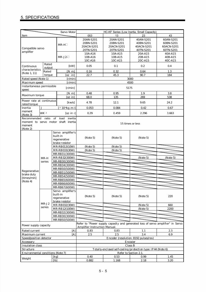
8/10/2019 Servo Motor - Instruction Manual SH(NA)-3181-D (03.00)
http://slidepdf.com/reader/full/servo-motor-instruction-manual-shna-3181-d-0300 54/368
5 - 5
5. SPECIFICATIONS
HC-KF Series (Low Inertia, Small Capacity)Servo Motor Item 053 13 23 43
MR-H
20AN-S20120BN-S201
20ACN-S201
20TN-S201
20AN-S20120BN-S201
20ACN-S201
20TN-S201
40AN-S20140BN-S201
40ACN-S201
40TN-S201
60AN-S20160BN-S201
60ACN-S201
60TN-S201Compatible servoamplifier
MR-J 2-10A-A1610B-A1610C-A16
10A-A1510B-A1510C-A15
20A-A1520B-A1520C-A15
40A-A1540B-A1540C-A15
Ratedoutput [kW] 0.05 0.1 0.2 0.4
[N ⋅ m] 0.16 0.32 0.64 1.3
Continuouscharacteristics(Note 1, 11) Rated
torque [oz ⋅ in] 22.7 45.3 90.7 184Rated speed (Note 1) [r/min] 3000Maximum speed [r/min] 4500Instantaneous permissiblespeed
[r/min] 5175
[N ⋅ m] 0.48 0.95 1.9 3.8Maximum torque
[oz ⋅ in] 68.0 135 269 538Power rate at continuousrated torque [kw/s] 4.78 12.1 9.65 24.2
J [ 10 -4kg ⋅ m 2] 0.053 0.084 0.42 0.67Inertiamoment(Note 3) WK 2 [oz ⋅ in 2] 0.29 0.459 2.296 3.663
Recommended ratio of load inertiamoment to servo motor shaft inertiamoment(Note 2)
15 times or less
Servo amplifier'sbuilt-inregenerativebrake resistor
(Note 5) (Note 5) (Note 5)
M R-RB013(10W) (N ote 5) (N ote 5)M R-RB033(30W) (N ote 5) (N ote 5)
MR-RB31(300W)MR-RB32(300W) (Note 5) (Note 5)MR-RB30(300W)MR-RB34(300W)MR-RB50(500W)MR-RB51(500W)MR-RB54(500W)MR-RB65(600W)MR-RB66(600W)
MR-Hseries
MR-RB67(600W)Servo amplifier'sbuilt-inregenerativebrake resistor
(Note 5) (Note 5) (Note 5) 220
MR-RB032(30W) (Note 5) 660MR-RB12(100W) (Note 5) 2200MR-RB32(300W)MR-RB30(300W)
Regenerativebrake duty[times/min](Note 4)
MR-J 2series
MR-RB50(500W)
Power supply capacity Refer to "Power supply capacity and generated loss of servo amplifier" in Servo
Amplifier Instruction Manual.Rated current [A] 0.83 0.83 1.1 2.3Maximum current [A] 2.5 2.5 3.4 6.9Speed/position detector E ncoder (resolution: 8192 pulses/rev)Accessory EncoderInsulation class Class BStructure Total ly-enclosed sel f-cool ing (protection type: IP44 (Note 6)E nvironmental conditions (Note 7) Refer to Section 2.1.
[kg] 0.40 0.53 0.99 1.45Weight[lb] 0.882 1.168 2.18 3.20

8/10/2019 Servo Motor - Instruction Manual SH(NA)-3181-D (03.00)
http://slidepdf.com/reader/full/servo-motor-instruction-manual-shna-3181-d-0300 55/368

8/10/2019 Servo Motor - Instruction Manual SH(NA)-3181-D (03.00)
http://slidepdf.com/reader/full/servo-motor-instruction-manual-shna-3181-d-0300 56/368
5 - 7
5. SPECIFICATIONS
HA-LF Series (Three-phase, For 400VAC, Low Inertia, Large Capacity)Servo Motor Item 30K24 37K24 45K24 55K24
Compatible servoamplifier
MR-H AN4/BN4/ACN4/TN4
30K 37K 45K 55K
Compatible converter unit MR-HP55KA4Ratedoutput
[kW] 30 37 45 55
[N ⋅ m] 143 177 215 263
Continuouscharacteristics(Note 1, 11)
Ratedtorque [oz ⋅ in] 20250.6 25065.4 30446.6 37244.0
Rated speed (Note 1) [r/min] 2000
Maximum speed [r/min] 2000
Instantaneous permissiblespeed
[r/min] 2300
[N ⋅ m] 358 442 537 657Maximum torque
[oz ⋅ in] 50697.2 62592.6 76045.8 930392
Power rate at continuous
rated torque [kW/s] 373 480 427 526
J [ 10-4kg ⋅ m 2] 550 650 1080 1310Inertia moment(Note 3) WK 2 [oz ⋅ in 2] 3007.095 3553.84 5904.84 7162.354
Recommended ratio of load inertia momentto servo motor shaft inertia moment(Note 2)
10 times or less
MR-RB136-4(1300W)
58 49 30 24Regenerative brake duty[times/min] (Note 4)
Three MR-B138-4’s(3900W)
174 147 89 73
Power supply capacity Refer to "Power supply capacity and generated loss of servo amplifier" in Servo
Amplifier I nstruction Manual.Rated current [A] 83 102 131 143
Maximum current [A] 208 255 328 358
Speed/position detector E ncoder (resolution: 16384 pulses/rev)
Voltage, frequency Three-phase 380 to 460VAC 50/60HzPowersupply
Powerconsumption
[W] 63(50Hz)/83(60Hz) 110(50Hz)/150(60Hz)
Ratedcurrent
[A] 0.09(50Hz)/0.11(60Hz) 0.20(50Hz)/0.22(60Hz)
Cooling fan
Speed [r /min] 2720(50Hz)/2980(60Hz) 2650(50Hz)/3000(60Hz)
Accessories Encoder, oil seal
Insulation class Class F
Structure Totally-enclosed self-cooling (protection type: I P44)Weight (Note 3) Refer to Section 2.1.
[kg] 160 180 230 250Weight (Note 3)
[lb] 352.739 396.832 507.063 551.155
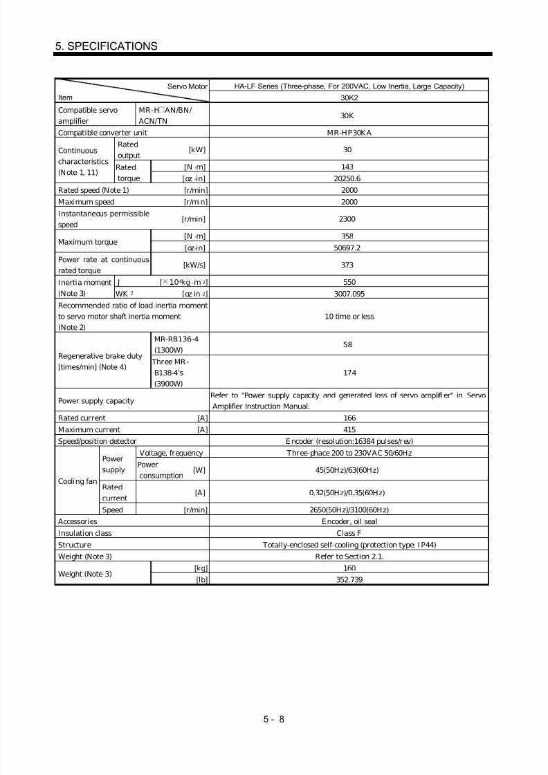
8/10/2019 Servo Motor - Instruction Manual SH(NA)-3181-D (03.00)
http://slidepdf.com/reader/full/servo-motor-instruction-manual-shna-3181-d-0300 57/368

8/10/2019 Servo Motor - Instruction Manual SH(NA)-3181-D (03.00)
http://slidepdf.com/reader/full/servo-motor-instruction-manual-shna-3181-d-0300 58/368
5 - 9
5. SPECIFICATIONS
HC-MFS Series(Ultra low inertia, small capacity)
HA-KFS Series(Low inertia, small capacity)
Servo Motor
Item 053 13 23 43 73 053 13 23 43Applicable servoamplifier
MR-J 2S- A/B 10 10 20 40 70 10 10 20 40
Rated output [kW] 0.05 0.1 0.2 0.4 0.75 0.05 0.1 0.2 0.4[N ⋅ m] 0.16 0.32 0.64 1.3 2.4 1.62 3.25 6.5 13
(Note 1,11)Continuousduty
Ratedtorque [oz ⋅ in] 22.7 45.3 90.7 184 340 22.7 45.3 90.7 184
(Note 1) Rated speed [r/min] 3000 3000Maximum speed [r/min] 4500 4500Permissible instantaneous speed [r/min] 5175 5175
[N ⋅ m] 0.48 0.95 1.9 3.8 7.2 0.48 0.95 1.9 3.8Maximum torque
[oz ⋅ in] 68.0 135 269 538 1020 68.0 135 269 538Power rate at continuous rated torque
[kW/s] 13.47 34.13 46.02 116.55 94.43 4.78 12.1 9.65 24.2
J [ 10 -4kg ⋅ m 2] 0.019 0.03 0.088 0.143 0.6 0.053 0.084 0.42 0.67(Note 3)Inertia moment WK 2 [oz ⋅ in 2] 0.104 0.16 0.48 0.78 3.28 0.29 0.459 2.296 3.663(Note 2) Recommended ratio of load inertiamoment to servo motor shaft inertia moment 30 times or less 10 times or less
Servo amplifier' built-in regenerative brakeresistor
(Note 5) (Note 5) (Note 5) 1010 400 (Note 5) (Note 5) (Note 5) 220
MR-RB032(30W) 3000 600 (Note 5) (Note 5) (Note 5) 660MR-RB12(100W) (Note5) 2400 (Note 5) (Note 5) (Note 5) 2200MR-RB32(300W)MR-RB30(300W)
(Note4)Regenerative brakeduty[times/min]
MR-J 2Sseries
MR-RB50(500W)
Power supply capacity Refer to ″ Power supply equipment capacity and generated loss of servo amplifiers"
in Servo Amplifier Instruction Manual.Rated current [A] 0.85 0.85 1.5 2.8 5.1 0.83 0.83 1.1 2.3Maximum current [A] 2.6 2.6 5 9 18 2.5 2.5 3.4 6.9Speed/position detector Encoder (resolution : 131072 pulse/rev) Encoder (resolution : 131072 pulse/rev)Accessories Encoder Encoder, V ring
Insulation class Class B Class BStructure
Totally-enclosed, self-cooled(protection type: IP55 (Note 6,7))
Totally-enclosed, self-cooled(protection type: IP44 (Note 6,12))
(Note 7) Envi ronmental condi tions Refer to section 2.1 Refer to section 2.1[kg] 0.4 0.53 0.99 1.45 3.0 0.40 0.53 0.99 1.45
(Note 3) Weight[lb] 0.88 1.17 2.18 3.20 6.61 0.882 1.168 2.18 3.20

8/10/2019 Servo Motor - Instruction Manual SH(NA)-3181-D (03.00)
http://slidepdf.com/reader/full/servo-motor-instruction-manual-shna-3181-d-0300 59/368
5 - 10
5. SPECIFICATIONS
HC-SFS1000r/min Series(Middle inertia, middle capacity)
HC-SFS 2000r/min Series(Middle inertia, middle capacity)
Servo Motor
Item 81 121 201 301 52 102 152 202 352 502 702Applicable servoamplifier
MR-J 2S- A/B 100 200 200 350 60 100 200 200 350
Rated output [kW] 0.85 1.2 2.0 3.0 0.5 1.0 1.5 2.0 3.5 5.0 7.0[N ⋅ m] 8.12 11.5 19.1 28.6 2.39 4.78 7.16 9.55 16.7 23.9 33.4
(Note 1,11)Continuousduty
Ratedtorque [oz ⋅ in] 1151 1630 2707 4053 339 677 1015 1353 2367 3387 4733
(Note 1) Rated speed [r/min] 1000 2000Maximum speed [r/min] 1500 1200 3000 2500 2000Permissible instantaneous speed [r/min] 1725 1380 345 2850 2300
[N ⋅ m] 24.4 34.4 57.3 85.9 7.16 14.4 21.6 28.5 50.1 71.6 100.0Maximum torque
[oz ⋅ in] 3458 4875 8120 12173 1015 2041 3061 4039 7100 10146 14171Power rate at continuous rated torque
[kW/s] 32.9 30.9 44.5 81.3 8.7 16.7 25.6 21.5 34.1 56.5 69.7
J [ 10-4kg ⋅ m 2] 20.0 42.5 82 101 6.6 13.7 20.0 4.5 82.0 101 160(Note 3)Inertia moment WK 2 [oz ⋅ in 2] 109 232 448 552 36.1 74.9 109 232 448 552 875(Note 2) Recommended ratio of load inertiamoment to servo motor shaft inertia moment
15 times or less 15 times or less
Servo amplifier' built-in regenerative brakeresistor
140 240 100 84 56 54 136 64 31
MR-RB032(30W) 220 165 80MR-RB12(100W) 740 560 270MR-RB32(300W) 2220 1680 810MR-RB30(300W) 730 330 250 408 192 95
(Note4)Regenerative brakeduty[times/min]
MR-J 2Sseries
MR-RB50(500W) 1216 550 430 680 320 158P ower supply capacity Refer to ″ Power supply equipment capacity and generated loss of servo amplifiers"
in Servo Amplifier Instruction Manual.Rated current [A] 5.1 7.1 9.6 16 3.2 6 9 11 17 28 35Maximum current [A] 15.3 21.3 28.8 48 9.6 18 27 33 51 84 105
Speed/position detector Encoder
(resolution: 131072 pulse/rev)Encoder
(resolution: 131072 pulse/rev)
Accessories Encoder Oil seal Encoder Oil sealInsulation class Class F Class F
Structure Totally-enclosed, self-cooled
(protection type: IP 65) Totally-enclosed, self-cooled
(protection type: IP65(Note 12))(Note 7) Environmental conditions Refer to section 2.1 Refer to section 2.1
[kg] 9.0 12 19 23 5.0 7.0 9.0 12.0 19.0 23 32(Note 3) Weight
[lb] 19.8 26.5 41.9 50.7 11.0 15.4 19.8 26.5 41.9 50.7 70.5

8/10/2019 Servo Motor - Instruction Manual SH(NA)-3181-D (03.00)
http://slidepdf.com/reader/full/servo-motor-instruction-manual-shna-3181-d-0300 60/368
5 - 11
5. SPECIFICATIONS
HC-SFS 3000r/min Series(Middle inertia, middle capacity)
HC-RFS Series(Low inertia, small capacity)
Servo Motor
Item 53 103 153 203 353 103 153 203 353 503Applicable servoamplifier
MR-J 2S- A/B 60 100 200 200 350 200 200 350
Rated output [kW] 0.5 1.0 1.5 2.0 3.5 1.0 1.5 2.0 3.5 5.0[N ⋅ m] 1.59 3.18 4.78 6.37 11.1 3.18 4.78 6.37 11.1 15.9
(Note 1,11)Continuousduty
Ratedtorque [oz ⋅ in] 225 451 677 903 1573 451 677 903 1573 2253
(Note 1) Rated speed [r/min] 3000 3000Maximum speed [r/min] 3000 4500Permissible instantaneous speed [r/min] 3450 5175
[N ⋅ m] 4.77 9.55 14.3 19.1 33.4 7.95 11.9 15.9 27.9 39.7Maximum torque
[oz ⋅ in] 676 1353 2026 2707 4733 1127 1686 2253 3954 5626Power rate at continuous rated torque
[kW/s] 3.8 7.4 11.4 9.5 15.1 67.4 120 176 150 211
J [ 10-4kg ⋅ m 2] 6.6 13.7 20.0 42.5 82.0 1.5 1.9 2.3 8.6 12.0(Note 3)Inertia moment WK 2 [oz ⋅ in 2] 36.1 74.9 109.3 232.4 448.3 8.2 10.4 12.6 47.0 65.6(Note 2) Recommended ratio of load inertiamoment to servo motor shaft inertia moment
15 times or less 5 times or less
Servo amplifier' built-in regenerative brakeresistor
25 24 82 24 14 1090 860 710
MR-RB032(30W) 73 36MR-RB12(100W) 250 120MR-RB32(300W) 750 360MR-RB30(300W) 250 70 42 3270 2580 2130
(Note4)Regenerativebrake duty[times/min]
MR-J 2Sseries
MR-RB50(500W) 410 110 70 5450 4300 3550
Power supply capacity Refer to ″ Power supply equipment capacity and generated loss of servo amplifiers"
in Servo Amplifier Instruction Manual.Rated current [A] 3.2 5.3 8.6 10.4 16.4 6.1 8.8 14 23 28M aximum current [A] 9.6 15.9 25.8 31.2 49.2 18.4 23.4 37 58 70
Speed/position detector Encoder
(resolution : 131072 pulse/rev)Encoder
(resolution : 131072 pulse/rev)
Accessories Encoder⋅
Oil seal Encoder⋅
Oil sealInsulation class Class F Class F
Structure Totally-enclosed, self-cooled
(protection type: IP 65) Totally-enclosed, self-cooled
(protection type: IP 65(Note 12))(Note 7) Envi ronmental condi tions Refer to section 2.1 Refer to section 2.1
[kg] 5.0 7.0 9.0 12 19 3.9 5.0 6.2 12.0 17.0(Note 3) Weight
[lb] 11.0 15.4 19.8 26.5 41.9 8.6 11.0 13.7 26.5 37.5

8/10/2019 Servo Motor - Instruction Manual SH(NA)-3181-D (03.00)
http://slidepdf.com/reader/full/servo-motor-instruction-manual-shna-3181-d-0300 61/368
5 - 12
5. SPECIFICATIONS
HC-UFS 2000r/min Series(Pancake type middle capacity)
HC-UFS 3000r/min Series(Pancake type small capacity)
Servo Motor
Item 72 152 202 352 502 13 23 43 73Applicable servoamplifier MR-J 2S A/B 70 200 350 10 20 40 70
Rated output 0.75 1.5 2.0 3.5 5.0 0.1 0.2 0.4 0.75[N ⋅ m] 3.58 7.16 9.55 16.7 23.9 0.32 0.64 1.3 2.4
(Note 1,11)Continuousduty
Ratedtorque [oz ⋅ in] 507 1015 1353 2367 3387 45 91 184 340
(Note 1) Rated speed [r/min] 2000 3000Maximum speed [r/min] 3000 2500 4500Permissible instantaneous speed [r/min] 3450 2875 5175
[N ⋅ m] 10.7 21.6 28.5 50.1 71.6 0.95 1.9 3.8 7.2Maximum torque
[oz ⋅ in] 1516 3061 4039 7100 10146 135 269 538 1020Power rate at continuous rated torque
[kW/s] 12.3 23.2 23.9 36.5 49.6 15.5 19.2 47.7 9.66
J [ 10-4kg ⋅ m 2] 10.4 22.1 38.2 76.5 115 0.066 0.241 0.365 5.90(Note 3)Inertia moment WK 2 [oz ⋅ in 2] 56.9 120.8 208.9 418.3 628.8 0.4 1.3 2.0 32.3(Note 2) Recommended ratio of load inertiamoment to servo motor shaft inertia moment 15 times or less 15 times or less
Servo amplifier' built-in regenerative brakeresistor
53 102 68 (Note5) (Note5) 410 41
MR-RB032(30W) 79 1230 62MR-RB12(100W) 87 4106 206MR-RB32(300W) 791MR-RB30(300W) 305 203
(Note4)Regenerativebrake duty[times/min]
MR-J 2Sseries
MR-RB50(300W) 508 338
Power supply capacity Refer to ″ Power supply equipment capacity and generated loss of servo amplifiers"
in Servo Amplifier Instruction Manual.Rated current [A] 5.4 9.7 14 23 28 0.76 1.5 2.8 4.3Maximum current [A] 16.2 29.1 42 69 84 2.5 4.95 9.24 12.9
Speed/position detector Encoder(resolution : 131072 pulse/rev)
Encoder(resolution : 131072 pulse/rev)
Voltage, frequencyPowersupply Power consumption [W]Rated current [A]
Coolingfan
Speed [r/min]Accessories Encoder ⋅Oil seal Encoder ⋅Oil sealInsulation class Class F Class B
Structure Totally-enclosed, self-cooled(protection type: I P65(Note9))
Totally-enclosed, self-cooled(protection type: I P65(Note9))
Environmental conditions Refer to secti on 2.1 Refer to secti on 2.1[kg] 8.0 11.0 16.0 20.0 24.0 0.8 1.5 1.7 5.0
(Note 3) Weight[lb] 17.6 24.3 35.3 44.1 52.9 1.8 3.3 3.7 11.0

8/10/2019 Servo Motor - Instruction Manual SH(NA)-3181-D (03.00)
http://slidepdf.com/reader/full/servo-motor-instruction-manual-shna-3181-d-0300 62/368
5 - 13
5. SPECIFICATIONS
Note: 1.When the power supply voltage drops, we cannot guarantee the output and rated speed.2.If the load inertia moment ratio exceeds the indicated value, please consult us.3.When the servo motor is equipped with reduction gear or electromagnetic brake, refer to the
corresponding outline dimension drawing. For the EN Standard- and UL/C-UL Standard-
compliant models, please consult us.4.The regenerative brake duty indicated is the permissible duty when the servo motor running
without load at the rated speed is decelerated to a stop. When a load is connected, the value inthe table is multiplied by 1/(m + 1), where m load inertia moment/motor inertia moment. Atthe speed higher than the rated, the permissible number of times is in inverse proportion to thesquare of (running speed/rated speed). When the running speed varies frequently or when theregenerative mode continues as in vertical feed, calculate regenerative heat generated duringoperation. Provisions must be made to keep this generated heat below the permissible value.
5. I f the effective torque is within the rated torque range, there are no restrictions on theregenerative duty.
6. E xcept for the shaft-through portion and connector end.7. When the equipment is to be used in places where it is subjected to oil and/or water, such as on
machine field sites, optional features apply to the equipment. Please contact.8. IP54 for the EN Standard-compliant model.9. E xcept the connector section.
10. Values for use of the supplied regenerative brake unit (regenerative brake resistor).11. 80%ED at low noise.
80%ED: Indicates the condition in which operation time at read torque accounts for 80% andthe other no-load time accounts for 20% in a single operation cycle.
Torque100% tb
tc time
tb 60 sec. (continuous operation time)
%ED tctb 100
12 When the servo motor is provided with the reduction gear, the protection type of the reductiongear section is IP44.
13. For the HC-UF73, HC-SF203 and HC-SF353, consult us since they may not be connecteddepending on the production period of the servo amplifier.

8/10/2019 Servo Motor - Instruction Manual SH(NA)-3181-D (03.00)
http://slidepdf.com/reader/full/servo-motor-instruction-manual-shna-3181-d-0300 63/368
5 - 14
5. SPECIFICATIONS
5.2 Torque Characteristics
POINT For machines which produce unbalance torque, e.g. vertical lift
applications, it is recommended to use the servo motor so that theunbalance torque will be within 70% of the rated torque.
(1) HC-MF/HC-MFS series
1000 2000 3000 40004500
Continuous operationregion
Speed [r/min]
T o r q u e
[ N m
]
0
0.2
0.4
0.6
[HC-MF053][HC-MFS053]
Short-durationoperation region
1000 2000 3000 40004500
Speed [r/min]
T o r q u e
[ N m
]
0
0.25
0.5
1.0
[HC-MF13][HC-MFS13]
0.75
Speed [r/min]
T o r q u e
[ N m
]
0
0.5
1.0
2.0
[HC-MF23][HC-MFS23]
1.5
1000 2000 3000 40004500
Continuous operationregion
Short-durationoperation region
Continuous operationregion
Short-durationoperation region
1000 2000 3000 40004500
Speed [r/min]
0
1.0
2.0
4.0
[HC-MF43][HC-MFS43]
3.0
T o r q u e [ N m ]
Short-durationoperation region
Speed [r/min]
1000 2000 3000 40004500
T o r q u e [ N m ]
0
2.0
4.0
8.0
[HC-MF73][HC-MFS73]
6.0 Short-durationoperation region
Continuous operationregion
Continuous operationregion
(2) HA-FF series
1000 2000 3000
T o r q u e [ N m
]
0
0.5
1.0
2.0
[HA-FF23]
1.5
4000
Speed [r/min]
T o r q u e [ N m
]
0
0.2
0.4
0.6
[HA-FF053]
1000 2000 3000 4000
Speed [r/min]
3000
T o r q u e [ N m
]
0
0.25
0.5
1.0
[HA-FF13]
0.75
1000 2000 4000
Speed [r/min]
Short-durationoperation region
Continuous operationregion
Continuous operationregion
Short-durationoperation region
Short-durationoperation region
Continuous operationregion

8/10/2019 Servo Motor - Instruction Manual SH(NA)-3181-D (03.00)
http://slidepdf.com/reader/full/servo-motor-instruction-manual-shna-3181-d-0300 64/368
5 - 15
5. SPECIFICATIONS
1000 2000 3000 4000Speed [r/min]
T o r q u e [ N m
]
0
1.0
2.0
3.0
[HA-FF33]
40000
1.0
2.0
4.0
[HA-FF43]
3.0
T o r q u e [ N m
]
1000 2000 3000Speed [r/min]
Short-durationoperation region
Continuous operationregion
Short-durationoperation region
Continuous operationregion
40001000 2000 3000Speed [r/min]
T o r q u e [ N m
]
0
2.0
4.0
6.0
[HA-FF63]
Short-durationoperation region
Continuous operationregion
(3) HC-SF/HC-SFS series
T o r q u e [ N m
]
10
20
40
[HC-SF121][HC-SFS121]
0
Speed [r/min]500 1000
30
T o r q u e [ N m
]
20
40
60
[HC-SF201][HC-SFS201]
0
Speed [r/min]500 1000
T o r q u e [ N m
]
10
20
30
[HC-SF81][HC-SFS81]
0 500 1000 1500Speed [r/min]
Short-durationoperation region
Continuous operationregion
Short-durationoperation region
Continuous operationregion
Continuous operationregion
Short-durationoperation region
T o r q u e [ N m
]
25
50
100
[HC-SF301]
[HC-SFS301]
0
Speed [r/min]500 1000
75
Continuous operationregion
Short-durationoperation region
T o r q u e [ N m
]
3
6
9
[HC-SF52][HC-SFS52]
0 1000 2000 3000Speed [r/min]
5
10
15
[HC-SF102][HC-SFS102]
0Speed [r/min]1000 2000 3000
8
16
24
[HC-SF152][HC-SFS152]
0Speed [r/min]1000 2000 3000
Continuous operationregion
Short-durationoperation region
Short-durationoperation region
Continuous operationregion
Short-durationoperation region
Continuous operationregion
T o r q u e [ N m
]
T o r q u e [ N m
]

8/10/2019 Servo Motor - Instruction Manual SH(NA)-3181-D (03.00)
http://slidepdf.com/reader/full/servo-motor-instruction-manual-shna-3181-d-0300 65/368
5 - 16
5. SPECIFICATIONS
T o r q u e [ N m ]
10
20
30
[HC-SF202][HC-SFS202]
0
Speed [r/min]
1000 2000
Short-durationoperation region
Continuous operationregion
[HC-SF352][HC-SFS352]
T o r q u e [ N m ]
20
40
60
0
Speed [r/min]
1000 2000
Short-durationoperation region
Continuous operationregion
20
60
80
[HC-SF502]
0
Speed [r/min]
1000 2000
40
Short-durationoperation region
Continuous operationregion
T o r q u e [ N m ]
T o r q u e [ N m
]
40
80
120
[HC-SF702]
0
Speed [r/min]
1000 2000
Short-durationoperation region
Continuous operationregion
T o r q u e [ N m
]
2
4
6
[HC-SF53][HC-SFS53]
01000 2000 3000
Speed [r/min]
Continuous operationregion
Short-durationoperation region
T o r q u e [ N m
]
4
8
12
[HC-SF103][HC-SFS103]
01000 2000 3000
Speed [r/min]
Continuous operationregion
Short-durationoperation region
T o r q u e [ N m
]
5
10
15
[HC-SF153][HC-SFS153]
0 1000 2000 3000
Speed [r/min]
Continuous operationregion
Short-durationoperation region
T o r q u e
[ N m
]
7
14
21
[HC-SF203][HC-SFS203]
0 1000 2000 3000
Speed [r/min]
Continuous operationregion
Short-durationoperation region
T o r q u e
[ N m
]
13
26
39
[HC-SF353][HC-SFS353]
0 1000 2000 3000
Speed [r/min]
Continuous operationregion
Short-durationoperation region

8/10/2019 Servo Motor - Instruction Manual SH(NA)-3181-D (03.00)
http://slidepdf.com/reader/full/servo-motor-instruction-manual-shna-3181-d-0300 66/368
5 - 17
5. SPECIFICATIONS
(4) HC-RF/HC-RFS series
1000 2000 3000 4000
Speed [r/min]
T o r q u e
[ N m
]
0
3
6
9
[HC-RF103][HC-RFS103]
Continuous operationregion
Short-durationoperation region
1000 2000 3000 4000
Speed [r/min]
T o r q u e
[ N m
]
0
5
10
15
[HC-RF153][HC-RFS153]
Continuous operationregion
Short-durationoperation region
Speed [r/min]
T o r q u e
[ N m
]
0
6
12
18
[HC-RF203][HC-RFS203]
1000 2000 3000 4000
Continuous operationregion
Short-durationoperation region
Speed [r/min]
T o r q u e [ N m
]
0
10
20
30
[HC-RF353]
1000 2000 3000 4000
Speed [r/min]
T o r q u e [ N m
]
0
15
30
45
[HC-RF503]
1000 2000 3000 4000
Continuous operationregion
Short-durationoperation region
Continuous operationregion
Short-durationoperation region
(5) HC-UF/HC-UFS series
T o r q u e
[ N m
]
4
8
12
[HC-UF72][HC-UFS72]
01000 2000 3000
Speed [r/min]
Continuous operationregion
Short-durationoperation region
T o r q u e
[ N m
]
8
16
24
[HC-UF152][HC-UFS152]
01000 2000 3000
Speed [r/min]
Continuous operationregion
Short-durationoperation region
T o r q u e
[ N m
]
10
20
30
[HC-UF202][HC-UFS202]
01000 2000 3000
Speed [r/min]
Continuous operationregion
Short-durationoperation region

8/10/2019 Servo Motor - Instruction Manual SH(NA)-3181-D (03.00)
http://slidepdf.com/reader/full/servo-motor-instruction-manual-shna-3181-d-0300 67/368
5 - 18
5. SPECIFICATIONS
500 100015002000Speed [r/min]
T o r q u e [ N
m ]
0
20
40
60
[HC-UF352][HC-UFS352]
2500
Continuous operationregion
Short-duration
operation region
500 100015002000Speed [r/min]
T o r q u e [ N m ]
0
20
40
80[HC-UF502]
2500
60Short-duration
operation region
Continuous operationregion
1000 2000 3000 40004500Speed [r/min]
T o r q u e [ N m
]
0
0.25
0.5
1.0
[HC-UF13][HC-UFS13]
0.75 Short-durationoperation region
Continuous operationregion
Speed [r/min]
T o r q u e [ N m
]
0
0.5
1.0
2.0
[HC-UF23][HC-UFS23]
1.5
1000 2000 3000 40004500
Short-durationoperation region
Continuous operationregion
1000 2000 3000 40004500Speed [r/min]
0
1.0
2.0
4.0
[HC-UF43][HC-UFS43]
3.0
T o r q u e
[ N m
]Short-durationoperation region
Continuous operationregion
Speed [r/min]
T o r q u e [ N m
]
0
2
4
8
[HC-UF73]
[HC-UFS73]
6
1000 2000 3000 40004500
Short-durationoperation region
Continuous operationregion
(6) HA-LH series
T o r q u e [ N m
]
50
200[HA-LH11K2]
0
Speed [r/min]1000 2000
100
150
Short-durationoperation region
Continuous operationregion
T o r q u e [ N m
]
100
250[HA-LH15K2]
0
Speed [r/min]1000 2000
200Short-durationoperation region
Continuous operationregion
T o r q u e [ N m
]
100
300[HA-LH22K2]
0
Speed [r/min]1000 2000
200
Short-durationoperation region
Continuous operationregion

8/10/2019 Servo Motor - Instruction Manual SH(NA)-3181-D (03.00)
http://slidepdf.com/reader/full/servo-motor-instruction-manual-shna-3181-d-0300 68/368
5 - 19
5. SPECIFICATIONS
(7) HC-KF/HC-KFS series
1000 2000 3000 400045000
0.2
0.4
0.8[HC-KFS053]
0.6
[HC-KF053]
1000 2000 3000 400045000
0.25
0.5
1.0[HC-KFS13]
0.75
[HC-KF13] [HC-KF23][HC-KFS23]
T o r q u e
[ N m
]
T o r q u e
[ N m
]
Speed [r/min]Speed [r/min]
Continuous operationregion
Continuous operationregion
Short-durationoperation region
Short-durationoperation region
Speed [r/min]
T o r q u e [ N m
]
0
0.5
1.0
2.0
1.5
1000 2000 3000 40004500
Continuous operationregion
Short-durationoperation region
[HC-KF43]
[HC-KFS43]
1000 2000 3000 40004500Speed [r/min]
0
1.0
2.0
4.0
3.0
T o r q u e [ N m
]Short-durationoperation region
Continuous operationregion
(8) HC-AQ series
10002000300040000
0.025
0.05
0.1
5000
0.075
Short-durationoperation region
Continuous operationregion
[HC-AQ0135]
Speed [r/min]10002000300040000
0.05
0.1
0.1
5000
0.15
[HC-AQ0235]
Speed [r/min]
Short-durationoperation region
Continuous operationregion
[HC-AQ0335]
T o r q u e [ N m
]
1000 2000 3000 40000
0.1
0.3
4500
0.2
Short-durationoperation region
Continuous operationregion
Speed [r/min]
T o r q u e [ N m
]
T o r q u e [ N m
]

8/10/2019 Servo Motor - Instruction Manual SH(NA)-3181-D (03.00)
http://slidepdf.com/reader/full/servo-motor-instruction-manual-shna-3181-d-0300 69/368
5 - 20
5. SPECIFICATIONS
(9) HC-LF series
T o r q u e [ N m
]
[HA-LF30K24]
0
Speed [r/min]
100
400
1000 2000
300
200
Short-durationoperation region
Continuous operationregion
T o r q u e [ N m
]
0
Speed [r/min]
[HA-LF37K24]
200
600
1000 2000
400Short-durationoperation region
Continuous operationregion
T o r q u e [ N m
]
0
Speed [r/min]
[HA-LF45K24]
200
600
1000 2000
400
Short-duration
operation region
Continuous operationregion
T o r q u e [ N m
]
0
Speed [r/min]
[HA-LF55K24]
200
800
1000 2000
600
400
Short-durationoperation region
Continuous operationregion
T o r q u e [ N m
]
0
Speed [r/min]
[HA-LF30K2]
100
400
1000 2000
300
200
Short-durationoperation region
Continuous operationregion

8/10/2019 Servo Motor - Instruction Manual SH(NA)-3181-D (03.00)
http://slidepdf.com/reader/full/servo-motor-instruction-manual-shna-3181-d-0300 70/368
5 - 21
5. SPECIFICATIONS
5.3 Servo Motors with Reduction Gears
CAUTIONThe servo motor with reduction gear must be installed in the specified direction.Otherwise , it can leak oil, leading to a fire or fault.
Servo motors are available with reduction gears designed for: general industrial machines and precisionapplications.Servo motors with electromagnetic brakes are also available.
(1) Manufacturing range of servo motor with reduction gear Servo motors with reduction gears that may be manufactured are indicated by symbols (G1(H), G2) inthe following table. G1 (H) and G2 are symbols appended to the servo motor models.
For General Industrial Machines For Precision ApplicationsReduction Gear SeriesReduction ratio
Servo Motor (Note)
1/51/6
(Note)
1/101/11
(Note)
1/121/17
(Note)
1/201/29
(Note)
1/301/35 1/43 1/59 1/5 1/9 1/10 1/15 1/20 1/25 1/29 1/45
HC-K F23 • 43 G1 G1 G1 G2 G2 G2 G2
HC-K F053 to 43HC-K FS053 to 43 G1 G1 G1 G2 G2 G2 G2
HC-M F053 to 73HC-M FS053 to 73
G1 G1 G1 G2 G2 G2 G2
HA-FF053 G1 G1 G1 G1 G2 G2 G2 G2HA-FF13 G1 G1 G1 G1 G2 G2 G2 G2 G2HA-FF23 G1 G1 G1 G1 G2 G2 G2 G2 G2 G2HA-FF33 G1 G1 G1 G1 G2 G2 G2 G2 G2HA-FF43 • 63 G1 G1 G1 G1 G2 G2 G2 G2 G2HC-SF52 to 202HC-SF S52 to 202
G1(H)
G1(H)
G1(H)
G1(H)
G1(H)
G1(H)
G1(H)
G2 G2 G2 G2 G2
HC-SF352HC-SFS352
G1(H)
G1(H)
G1(H)
G1(H)
G1(H)
G1(H)
G1(H)
G2 G2 G2
HC-SF502 G1(H) G1(H) G1(H) G1(H) G1(H) G2 G2
HC-SF702 G1
(H)G1(H)
G1(H)
G1(H)
G1(H)
G2
HC-RF 103 to 203HC-RF S103 to 203
G2 G2 G2 G2 G2
HC-RF353 G2 G2 G2 G2HC-RF503 G2 G2 G2
Note : Reduction ratios for general industrial machines are nominal values. For actual reduction ratios, refer to (2) and (3) in this section.
(2) HC-MF/HC-KF series
Reduction Gear SeriesFor General Industrial Machines
(HC-KF G1/HC-MF G1)(HC-KFS G1/HC-MFS G1)
For Precision Applications(HC-KF G2/HC-MF G2)
(HC-KFS G2/HC-MFS G2)
Mounting Method Flange mountingMounting direction In any directions
Grease lubrication (Already packed) Grease lubrication (Already packed)50 ⋅ 100W 200 to 750W
Lubrication Recommendedgrease
Mobilplex 46Mobil Oil
Mobil tac 81Mobil Oi l
LDR101BV American Oil Center Research
Output shaft rotating direction Same as the servo motor output shaft direction.With electromagnetic brake AvailableBacklash 60 minutes or less at reduction gear output shaft 3 minutes or less at reduction gear output shaftPermissible load inerti a momentratio (when converting into the
servo motor shaft)
HC-KF ,HC-K FS:10 times or lessHC-MF,HC-MFS:25 times or less
Permissible speed(at servo motor shaft)
4500 r/min

8/10/2019 Servo Motor - Instruction Manual SH(NA)-3181-D (03.00)
http://slidepdf.com/reader/full/servo-motor-instruction-manual-shna-3181-d-0300 71/368
5 - 22
5. SPECIFICATIONS
The actual reduction ratios of the servo motors with reduction gears designed for general industrialmachines are as listed below:
Servo Motor
NominalReduction Ratio
HC-KF053(B)G1HC-MF053(B)G1
HC-KFS053(B)G1HC-MFS053(B)G1
HC-KF13(B)G1HC-MF13(B)G1
HC-KFS13(B)G1HC-MFS13(B)G1
HC-KF23(B)G1HC-MF23(B)G1
HC-KFS23(B)G1HC-MFS23(B)G1
HC-KF43(B)G1HC-MF43(B)G1
HC-KFS43(B)G1HC-MFS43(B)G1
HC-MF73(B)G1
HC-MFS73(B)G1
1/5 9/44 19/96 1/5
1/12 49/576 25/288 525/6048
1/20 25/484 253/5000 625/12544
(3) HA-FF series
Reduction Gear SeriesFor General Industrial Machines
(HA-FF G1)For Precision Applications
(HA-FF G2)
Mounting Method Flange mounting
Mounting direction In any directions
Grease lubrication (Already packed) Grease lubrication (Already packed)
50 ⋅ 100W 200 to 600WLubrication Recommended
greaseSUMICO
LUBRICANT MOLYPS GREASE No.2
PYRONOCUNIVERSAL No.000
NIPPON PETRQLEUM
LDR101BJ American Oil Center Research
Output shaft rotating direction
Servo motor shaft and reduction gear outputshaft rotate in the same direction. F or theHA-F F053G1 1/30 and HA-FF3G1 1/30, how-ever, the servo motor shaft and reduction gearoutput shaft rotate in the opposite directions.
Servo motor shaft and reduction gearoutput-shaft rotate in the same direction.
With electromagnetic brake Available
Backlash 40 minutes to 1.5 ° Within 3 minutes
Permissible load inertia momentratio (when converting into theservo motor shaft)
5 times or less
Permissible speed(at servo motor shaft)
3000 r/min
The actual reduction ratios of the servo motors with reduction gears designed for general industrialmachines are as listed below:
Servo Motor Nominal Reduction Ratio
HA-FF053G1 HA-FF13G1 HA-FF23G1 HA-FF33G1 HA-FF43G1 HA-FF63G1
1/5 9/44 57/280 19/94 10/49
1/10 3/29 39/400 39/376 243/2401
1/20 99/1972 51/980 72/1363 153/28911/30 144/4205 1/30 11/329 27/784

8/10/2019 Servo Motor - Instruction Manual SH(NA)-3181-D (03.00)
http://slidepdf.com/reader/full/servo-motor-instruction-manual-shna-3181-d-0300 72/368
5 - 23
5. SPECIFICATIONS
(4) HC-SF series
Reduction Gear SeriesFor General Industrial Machines(HC-SF G1(H)/HC-SFS G1(H))
For Precision Applications(HC-SF G2/ HC-SFS G2)
Mounting method As in (a) in this section Flange mounting
Mounting direction As in (a) in this section I n any directionsAs in (a)(b) in this section Grease lubrication (Already packed)
Lubrication Recommendedgrease
As in (b) in this section LDR101BJ of American Oil Center
Research make
Output shaft rotating direction Opposite direction to the servo motor shaft Same direction as the servo motor shaft
With electromagnetic brake Available
Backlash 40 minutes to 2* at reduction gear output
shaft3 minutes or less at reduction gear outputshaft
Permissible load inertia momentratio (when converting into theservo motor shaft)
4 times or less 5 times or less
Permissible speed(at servo motor shaft) 2000[r/min]
0.5 to 1.5kW:3000[r/min]
2 to 3.5kW:2500[r/min]5 7kW:2000[r/min]
(a) Lubrication of reduction gears for general industrial machinesOil lubrication cannot be used in applications where the servo motor will move. Specify greaselubrication.For grease lubrication, the reduction gear is already grease-packed.For oil lubrication, pack the reduction gear with oil on the customer side.
MountingDirection
Shaft in Any Direction Shaft Horizontal Shaft Downward Shaft Upward
Reduction gear model
Reduction gear frame No.
CNHM(leg type) CNVM(flange type) CHHM(leg type) CHVM(flange type ) CVHM(leg type) CVVM(flange type ) CWHM(leg type) CWVM(flange type )
4105 Grease Grease4115 Grease Grease4135 (Note) Oil (Note) Oil (Note) Oil (Note) Oil Grease Grease4165 (Note) Oil (Note) Oil (Note) Oil (Note) Oil Grease Grease4175 Oil Oil Oil Oil4185 Oil Oil Oil Oil4195 Oil Oil Oil Oil
Note: Grease-lubricated type is also available.
The reduction gear frame numbers are as follows:Reduction Ratio
Servo Motor 1/6 1/11 1/17 1/29 1/35 1/43 1/59
HC-SF52(B)G1 (H)HC-SFS52(B)G1 (H)
4105 4115
HC-SF102(B)G1 (H)HC-SFS102(B)G1 (H)
4115 4135 4165
HC-SF152(B)G1 (H)HC-SFS152(B)G1 (H)
4115 4135 4165
HC-SF202(B)G1 (H)HC-SFS202(B)G1 (H)
4115 4165
HC-SF352(B)G1 (H)HC-SFS352(B)G1 (H)
4135 4165 4175
HC-SF502(B)G1 (H) 4165 4185HC-SF702(B)G1 (H) 4175 4185 4195

8/10/2019 Servo Motor - Instruction Manual SH(NA)-3181-D (03.00)
http://slidepdf.com/reader/full/servo-motor-instruction-manual-shna-3181-d-0300 73/368
5 - 24
5. SPECIFICATIONS
(b) Recommended lubricants1) Grease
Albania Grease/Shell OIL2) Lubricating oil
AmbientTemperature
° CCOSMO OIL
NISSEKIMITSUBISHI
OIL
IDEMITSUKOSAN
CO., LTD
GENERALOIL
ShellOIL
ESSO OIL Mobil OILJapanEnergy
-10 to 5 COSMOGEAR
SE68
BONNOCSP68
DIAMONDGEAR LUBE
SP68
DAPHNE CE68S
DAPHNE SUPERGEAR OIL
68
OmalaOils68
SPARTANEP68
Mobilgear626
(ISO VG68)
J OMO.Reductus
68
0 to 35 COSMOGEAR
SE100, 150
BONNOCSP
100, 150DIAMOND
GEAR LUBESP
100, 150
DAPHNE CE100S,150S
DAPHNE SUPERGEAR OIL
100, 150
GENERALSP
GEAROL100, 150
OmalaOils
100, 150
SPARTANEP150
Mobilgear629
(ISO VG150)
J OMO.Reductus100, 150
30 to 50 COSMOGEAR
SE200,320,460
BONNOCSP
200 to 460DIAMOND
GEAR LUBESP
220 to 460
DAPHNE CE220S to 460S
GENERALSP
GEAROL200 to 260
OmalaOils
200 to460
SPARTANEP220 to 460
Mobilgear630 to 634(ISO VG
220 to 460)
J OMO.Reductus
200 to 460
Lubricating oil fill amount ( )
Fill amount [ ]Reduction gear frame No.
Horizontal type Vertical type
4135 0.7 1.14165 1.4 1.04175 1.9 1.94185 2.5 2.04195 4.0 2.7
(c) Lubricating product changing intervals1) Grease:
20000 hours or 4 to 5 years2) Lubricant
Operation hours per dayChanging intervals
Less than 10 hours 10 to 24 hours
First time 500 hoursSecond time and later Half year 2500 hours
(5) HC-RF series
Reduction Gear Ser ies For P reci sion Appl ications (HC-RF G2/HC-RFS G2)
Mounting method Flange mounting
Mounting direction In any directions
Grease lubri cation (Already packed)Lubrication
Recommended grease LDR101BJ of American Oil Center Research make
Output shaft rotating direction Same direction as the servo motor shaft
With electromagnetic brake Available
Backlash Within 3 minutes at reduction gear output shaft
Permissible load inertia moment ratio(when converting into the servo motor shaft) 5 times or less
P ermissible speed (at servo motor shaft) 4000[r/min]

8/10/2019 Servo Motor - Instruction Manual SH(NA)-3181-D (03.00)
http://slidepdf.com/reader/full/servo-motor-instruction-manual-shna-3181-d-0300 74/368
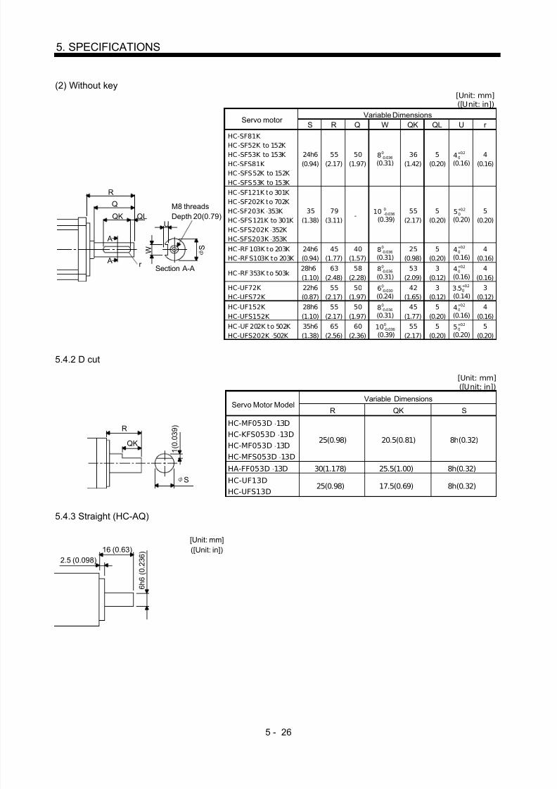
8/10/2019 Servo Motor - Instruction Manual SH(NA)-3181-D (03.00)
http://slidepdf.com/reader/full/servo-motor-instruction-manual-shna-3181-d-0300 75/368
5 - 26
5. SPECIFICATIONS
(2) Without key[Unit: mm]([Unit: in])
Variable DimensionsServo motor
S R Q W QK QL U r
HC-SF81K HC-SF52K to 152K HC-SF53K to 153K HC-SFS81K HC-SFS52K to 152K HC-SFS53K to 153K
24h6(0.94)
55(2.17)
50(1.97)
8 0-0.036
(0.31)36
(1.42)5
(0.20)4 +0.2
0
(0.16)4
(0.16)
HC-SF121K to 301K HC-SF202K to 702K HC-SF203K ⋅ 353K HC-SFS121K to 301K HC-SFS202K ⋅ 352K HC-SFS203K ⋅ 353K
35(1.38)
79(3.11)
- 10 0
-0.036
(0.39)55
(2.17)5
(0.20)5 +0.2
0
(0.20)5
(0.20)
HC-RF 103K to 203K HC-RFS103K to 203K
24h6(0.94)
45(1.77)
40(1.57)
8 0-0.036
(0.31)25
(0.98)5
(0.20)4 +0.2
0
(0.16)4
(0.16)
HC-RF 353K to 503k
28h6
(1.10)
63
(2.48)
58
(2.28)
8 0-0.036
(0.31)
53
(2.09)
3
(0.12)
4 +0.20
(0.16)
4
(0.16)HC-UF72K HC-UFS72K
22h6(0.87)
55(2.17)
50(1.97)
6 0-0.030
(0.24)42
(1.65)3
(0.12)3.5 +0.2
0
(0.14)3
(0.12)HC-UF152K HC-UFS152K
28h6(1.10)
55(2.17)
50(1.97)
8 0-0.036
(0.31)45
(1.77)5
(0.20)4 +0.2
0
(0.16)4
(0.16)
R
Q
QLQK
S
U
A
A
r
W
Section A-A
M8 threadsDepth 20(0.79)
HC-UF 202K to 502K HC-UFS202K ⋅ 502K
35h6(1.38)
65(2.56)
60(2.36)
10 0-0.036
(0.39)55
(2.17)5
(0.20)5 +0.2
0
(0.20)5
(0.20)
5.4.2 D cut
[Unit: mm]([Unit: in])
Variable DimensionsServo Motor Model
R QK SHC-MF053D ⋅ 13DHC-KFS053D ⋅ 13DHC-MF053D ⋅ 13DHC-MFS053D ⋅ 13D
25(0.98) 20.5(0.81) 8h(0.32)
HA-FF053D ⋅ 13D 30(1.178) 25.5(1.00) 8h(0.32)
R
S
QK 1 ( 0 . 0 3 9 )
HC-UF13DHC-UFS13D
25(0.98) 17.5(0.69) 8h(0.32)
5.4.3 Straight (HC-AQ)
16 (0.63)2.5 (0.098)
6 h 6 ( 0 . 2 3 6 )
[Unit: mm]
([Unit: in])

8/10/2019 Servo Motor - Instruction Manual SH(NA)-3181-D (03.00)
http://slidepdf.com/reader/full/servo-motor-instruction-manual-shna-3181-d-0300 76/368

8/10/2019 Servo Motor - Instruction Manual SH(NA)-3181-D (03.00)
http://slidepdf.com/reader/full/servo-motor-instruction-manual-shna-3181-d-0300 77/368
6 - 2
6. CHARACTERISTICS
HC-SF SeriesHC-SFS Series
HC-RF SeriesHC-RFS Series
HC-KF SeriesHC-KFS Series
HC-AQSeries
(Note 5) Servo Motor
Item
81B52B to 152B53b to 153B
121B to 301B202B to 702B203B ⋅ 353B
103B to203B
353B ⋅503B053B13B
23B ⋅43B0135B to
0335B
(Note 1) Type Spring-loaded safety brake(Note 4) Rated voltage 24V 0
-10% DCRated current at 20 ° C [A] 0.8 1.4 0.8 0.96 0.26 0.33 0.20Excitation coil resistance at 20 ° C [ ] 29 16.8 30 25 9.1 73 122Capacity [W] 19 34 19 23 6.3 7.9 4.8ON current [A] 0.2 0.4 0.25 0.24 0.18 0.18 0.11OFF current [A] 0.08 0.2 0.085 0.10 0.06 0.11 0.025
[N ⋅ m] 8.3 43.1 6.8 16.7 0.32 43.1 0.098Static friction torque
[oz ⋅ in] 1176 6108 964 2367 45 6108 13.878(Note 2) Release delay time [S] 0.04 0.1 0.03 0.04 0.03 0.1 0.02
AC off (Fig. a) 0.12 0.12 0.12 0.12 0.08 0.12 0.08Braking delay time(Note 2) [s] DC off (Fig.s b, c) 0.03 0.03 0.03 0.03 0.01 0.03 0.01
[N⋅
m] 400 4500 400 400 5.6 22.0 4.6Per braking [oz ⋅ in] 56683.3 637687.1 56683.3 56683.3 793.6 3117.6 63.882[N ⋅ m] 4000 45000 4000 4000 56 220 46
Permissible braking workPer hour
[oz ⋅ in] 566833 6376871 566833 566833 7936 31176 638.821
Brake looseness at servo motor shaft [degrees] 0.2 to 0.6 0.2 to 0.6 0.2 to 0.6 0.2 to 0.6 0.19 to
2.50.12 to
1.20.1 to
2.5Number of brakingcycles [times]
20000 20000 20000 20000 20000 20000 20000
[N ⋅ m] 200 1000 200 200 4 15 1Brake life (Note 3)
Work perbraking [oz ⋅ in] 28342 141708 28342 28342 567 2124.18 141.612
HC-UF SeriesHC-UFS Series
(Note 5) Servo Motor
Item 13B 23B ⋅43B 73B 72B ⋅152B 202B to 502B(Note 1) Type Spring-loaded safety brake(Note 4) Rated voltage 24V 0
-10% DCRated current at 20 ° C [A] 0.26 0.33 0.42 0.8 1.4Excitation coil r esistance at 20 ° C [ ] 91 73 57 29 16.8Capacity [W] 6.3 7.9 10 19 34ON current [A] 0.18 0.18 0.2 0.2 0.4OFF current [A] 0.06 0.11 0.12 0.08 0.2
[N ⋅ m] 0.32 1.3 2.4 8.3 43.1Static friction torque
[oz ⋅ in] 45 184 340 1176 6108(Note 2) Release delay time [S] 0.03 0.03 0.03 0.04 0.1
AC off (Fig. a) 0.08 0.1 0.12 0.12 0.12Braking delay time(Note 2) [s] DC off (Fig. b, c) 0.01 0.02 0.03 0.03 0.03
[N ⋅ m] 5.6 22 64 400 4500Perbraking [oz ⋅ in] 793.6 3117.6 9069.3 56683.3 637687.1
[N ⋅ m] 56 220 640 4000 45000Permissible braking work
Per hour[oz ⋅ in] 7936 31176 90693 566833 6376871
Brake looseness at servo motor shaft [degrees] 0.19 to 2.5 0.12 to 1.2 0.1 to 0.9 0.2 to 0.6 0.2 to 0.6Number of brakingcycles [times]
20000 20000 20000 20000 20000
[N ⋅ m] 4 15 32 200 1000Brake life (Note3)
Work perbraking [oz ⋅ in] 567 2126 4535 28342 141708
Note: 1. There is no manual release mechanism. When it is necessary to hand-turn the servo motor shaft for machine centering,etc., use a separate 24VDC power supply to release the brake electrically.
2. The value for initi al ON gap at 20 ° C.
3. The brake gap will increase as the brake lining wears, but the gap is not adjustable. The brake life indicated is thenumber of braking cycles after which adjustment will be required.4. 24VDC of the internal power output for interface (VDD) cannot be used. Always use a separate power supply.5. HC-SFS502/702, HC-RFS353/503 and HC-U FS352/502 are soon to be released.

8/10/2019 Servo Motor - Instruction Manual SH(NA)-3181-D (03.00)
http://slidepdf.com/reader/full/servo-motor-instruction-manual-shna-3181-d-0300 78/368
6 - 3
6. CHARACTERISTICS
(2) Electromagnetic brake power supply24VDC of the internal power output for interface (VDD) cannot be used. Prepare the following powersupply for use with the electromagnetic brake only. Examples of connection of the brake excitingpower supply are shown in the following diagram (a) to (c). (a) is for AC off, and (b) and (c) for DC off.
When DC is switched off, the braking delay time will be shortened, but a surge absorber must beinstalled on the brake terminal. For the selection of the surge absorber, refer to OPTI ONS ANDAUXILIARY EQUIPMENT of the Servo Amplifier Instruction Manual.
28V AC
SwitchRF
(a)
T
Electromagneticbrake
100V ACor
200V ACSwitch
RF
(b)
T
Electromagneticbrake
100V ACor
200V AC
VAR
Switch
(c)
Electromagneticbrake
VAR24VDC
T : TransformerRF : RectifierVAR : Surge absorber
(3) Coasting distanceAt an emergency stop, the servo motor wil l decelerate to a stop in the pattern shown in the followingdiagram. Here, the maximum coasting distance (during fast feed), Lmax, will be the area shown withthe diagonal line in the figure and can be calculated approximately with E quation 6.1. The effect of theload torque is greater near the stopping area. When the load torque is large, the servo motor will stopfaster than the value obtained in the equation.
Emergency stop
Brake current
Machine speed
V0
t1 t2 t3

8/10/2019 Servo Motor - Instruction Manual SH(NA)-3181-D (03.00)
http://slidepdf.com/reader/full/servo-motor-instruction-manual-shna-3181-d-0300 79/368
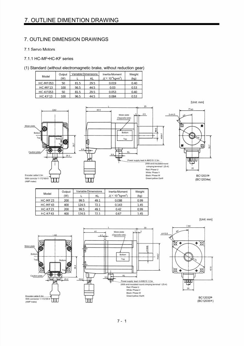
8/10/2019 Servo Motor - Instruction Manual SH(NA)-3181-D (03.00)
http://slidepdf.com/reader/full/servo-motor-instruction-manual-shna-3181-d-0300 80/368
7 - 1
7. OUTLINE DIMENTION DRAWING
7. OUTLINE DIMENSION DRAWINGS
7.1 Servo Motors
7.1.1 HC-MF•HC-KF series(1) Standard (without electromagnetic brake, without reduction gear)
Variable DimensionsModel
Output(W) L KL
Inertia MomentJ( 10 -4kg•m 2)
Weight(kg)
HC-MF053 50 81.5 29.5 0.019 0.40HC-MF13 100 96.5 44.5 0.03 0.53HC-KF053 50 81.5 29.5 0.053 0.40HC-KF13 100 96.5 44.5 0.084 0.53
Power supply lead 4-AWG19 0.3m
(With end-insulated roundcrimping terminal 1.25-4)
Red: Phase UWhite: Phase VBlack: Phase WGreen/yellow: Earth
Top
Bottom
Moter plate(Opposite side)
Encoder cable 0.3m
With connctor 1-172169-9
(AMP make)
Moter plate
25.2
25
3 0 h 7
2.55
8 h 6
20
2- 4.5 4 5 °
4040.5
L
2 8 . 7
6.8
42
Top
Bottom
3 5 . 7
KL9.9
BC12031(BC12034 )
Caution plate
Top
Bottom4 6
[Unit: mm]
Variable DimensionsModel
Output(W) L KL
Inertia MomentJ( 10 -4kg•m 2)
Weight(kg)
HC-MF23 200 99.5 49.1 0.088 0.99HC-MF43 400 124.5 72.1 0.143 1.45HC-KF23 200 99.5 49.1 0.42 0.99HC-KF43 400 124.5 72.1 0.67 1.45
Encoder cable 0.3mWith connector 1-172169-9(AMP make)
Power supply lead 4-AWG19 0.3m
Red: Phase UWhite: Phase VBlack: Phase WGreen/yellow: Earth
60
4 5 °
4- 5.8Motor plate
(Opposite side)
30
1 4 h 6Motor plate
Bottom
Top Bottom
Top
62
L
41
2.7
Bottom
Top
10.6
5 0 h 7
(With end-insulated round crimping terminal 1.25-4)
20
3 8 . 4
7 0
4 2 . 8
9.9KL
BC12032
7 3
Caution plate
25.2
(BC12035 )
[Unit: mm]

8/10/2019 Servo Motor - Instruction Manual SH(NA)-3181-D (03.00)
http://slidepdf.com/reader/full/servo-motor-instruction-manual-shna-3181-d-0300 81/368
7 - 2
7. OUTLINE DIMENSION DRAWING
ModelOutput
(W)Inertia MomentJ( 10 -4kg•m 2)
Weight(kg)
HC-MF73 750 0.6 3
4 8 . 7
Encoder cable 0.3mWith connector 1-172169-9(AMP make)
Power supply lead 4-AWG19 0.3m
Red: Phase U
White: Phase VBlack: Phase WGreen/yellow: Earth
9 0
80
4 5 °4- 6.6
Motor plate(Opposite side)
142
8 3
40
1 9 h 6
7 0 h 7
5 8 . 1
20
86.7
(With end-insulated round crimping terminal 1.25-4)
Top
Bottom
TopBottom
25.2
82
39
2.7
Top
9.911
Motor plate
Bottom
BC12033
Caution plate
[Unit: mm]
(2) With electromagnetic brakeVariable Dimensions
ModelOutput
(W) L KLBraking Force
(N•m)Inertia MomentJ( 10 -4kg•m 2)
Weight(kg)
HC-MF053B 50 109.5 29.5 0.32 0.022 0.75HC-MF13B 100 124.5 44.5 0.32 0.032 0.89HC-KF053B 50 109.5 29.5 0.32 0.056 0.75HC-KF13B 100 124.5 44.5 0.32 0.087 0.89
Motor plate(Opposite side)
Top
Bottom
Power supply lead 4-AWG19 0.3m
Red: Phase UWhite: Phase VBlack: Phase WGreen/yellow: Earth
40
2- 4.5
KL9.9
6.8
42
Brake lead2-0.3 0.3m(With end-insulated roundcrimping terminal 1.25-4)
3 5 . 7
20
8 h 6
3 0 h 7
5 2.5
25L
40.5
65.5
Motor plate
Top
Bottom
Top
Bottom
25.2
2 8 . 7
2Encoder cable 0.3mWith connector 1-172169-9(AMP make)
Caution plate
(With end-insulated round crimping terminal 1.25-4)
(BC12039 )BC12036
4 5 °
4 6
[Unit: mm]

8/10/2019 Servo Motor - Instruction Manual SH(NA)-3181-D (03.00)
http://slidepdf.com/reader/full/servo-motor-instruction-manual-shna-3181-d-0300 82/368
7 - 3
7. OUTLINE DIMENSION DRAWING
Variable DimensionsModel
Output(W) L KL
Braking Force(N•m)
Inertia MomentJ( 10 -4kg•m 2)
Weight(kg)
HC-MF23B 200 131.5 49.1 1.3 0.136 1.6HC-MF43B 400 156.5 72.1 1.3 0.191 2.1HC-KF23B 200 131.5 49.1 1.3 0.47 1.6
HC-KF43B 400 156.5 72.1 1.3 0.72 2.1
Brake lead
2-0.3 2 0.3m(With end-insulated roundcrimping terminal 1.25-4)
Power supply lead 4-AWG19 0.3m
Red: Phase UWhite: Phase VBlack: Phase WGreen/yellow: Earth
Encoder cable 0.3mWith connector 1-172169-9(AMP make)
62
25.2
3 3 . 4
68 9.9KL
41
2.7
L 30
7 3Motor plate(Opposite side)
Top
Bottom 5 0 h 7
60
4 5
7 0
4 2 . 8
4- 5.8
10.6
TopBottom
Top
Bottom
BC12037
20
1 4 h 6
(With end-insulated round crimping terminal 1.25-4)
Motor plate
Caution plate
(BC12039 )
[Unit: mm]
ModelOutput
(W)Braking Force
(N•m)
Inertia MomentJ( 10 -4kg•m 2)
Weight(kg)
HC-MF73B 750 2.4 0.725 4.0
Encoder cable 0.3m
With connector 1-172169-9(AMP make)
Brake lead2-0.3 0.3m(With end-insulated roundcrimping terminal 1.25-4)
2
Power supply lead 4-AWG19 0.3m
Red: Phase U
White: Phase VBlack: Phase WGreen/yellow: Earth
Motor plate(Opposite side)
Motor plate
82
Top
Bottom
Top
Bottom
25.2
4 8 . 7
177.5
39
2.7
11
72
86.79.9
(With end-insulated round crimping terminal 1.25-4)
BC12038
40
38
80
Caution plate
Top
Bottom
19.5
5 8 . 1
20
1 9 h 6
7 0 h 7
4 5 °
4- 6.6
9 0
[Unit: mm]

8/10/2019 Servo Motor - Instruction Manual SH(NA)-3181-D (03.00)
http://slidepdf.com/reader/full/servo-motor-instruction-manual-shna-3181-d-0300 83/368
7 - 4
7. OUTLINE DIMENSION DRAWING
(3) With reduction gear for general industrial machine(a) Without electromagnetic brake
Variable DimensionsModel
Output(W) L KL
ReductionGear Model
Reduction Ratio(Actual Reduction Ratio)
Inertia MomentJ( 10 -4kg•m 2)
BacklashWeight
(kg)
HC-MF053G1 50 126 74 K6505 1/5(9/44) 0.055 60min. max. 1.4HC-MF053G1 50 144 92 K6512 1/12(49/576) 0.077 60min. max. 1.8HC-MF053G1 50 144 92 K6520 1/20(25/484) 0.059 60min. max. 1.8HC-KF053G1 50 126 74 K6505 1/5(9/44) 0.090 60min. max. 1.4HC-KF053G1 50 144 92 K6512 1/12(49/576) 0.112 60min. max. 1.8HC-KF053G1 50 144 92 K6520 1/20(25/484) 0.094 60min. max. 1.8
2 8 . 7
25.2
"Rotation direction"
For forward rotation command
For reverse rotation command
M4 threads,depth 8
Encoder cable 0.3mWith connector 1-172169-9(AMP make)
Power supply lead 4-AWG19 0.3m (With end-insulated round crimping terminal 1.25-4)
Red: Phase UWhite: Phase VBlack: Phase WGreen/yellow: Earth
4 5 °
Motor plate
Motor plate
(Opposite side)
42 40.5
Caution plate
L
6.8
9.9KL
8 6.5
60.5
25
4- 7
3 5 . 7
20
1 6 h 6 4 8
6 0 h 7
65
BC12066(BC12086 )
Bottom
Top Bottom
Top
28
Bottom
Top
7 5
8 8
[Unit: mm]
Variable DimensionsModel
Output(W) L KL
ReductionGear Model
Reduction Ratio(Actual Reduction Ratio)
Inertia MomentJ( 10 -4kg•m 2)
BacklashWeight
(kg)
HC-MF13G1 100 141 89 K6505 1/5(9/44) 0.067 60min. max. 1.5HC-MF13G1 100 159 107 K6512 1/12(49/576) 0.089 60min. max. 1.9HC-MF13G1 100 159 107 K6520 1/20(25/484) 0.071 60min. max. 1.9HC-KF13G1 100 141 89 K6505 1/5(9/44) 0.121 60min. max. 1.5HC-KF13G1 100 159 107 K6512 1/12(49/576) 0.143 60min. max. 1.9HC-KF13G1 100 159 107 K6520 1/20(25/484) 0.125 60min. max. 1.9
2 8 . 7
25.2
25
8 6.5
28
60.5
"Rotation direction"For forward rotation command
For reverse rotation command
Encoder cable 0.3mWith connector 1-172169-9(AMP make)
Power supply lead 4-AWG19 0.3m (With end-insulated round crimping terminal 1.25-4)
Red: Phase UWhite: Phase VBlack: Phase W
Green/yellow: Earth
4 5 °
Motor plate
Motor plate(Opposite side)
Caution plate
42 40.5
9.9KL
L
1 6 h 6 4 8
6 0 h 7
4- 7
7 5
3 5 . 7
M4 threads,depth 8
20
6.8
65
Bottom
Top Bottom
Top
Top
Bottom
BC12067(BC12087 )
8 8
[Unit: mm]

8/10/2019 Servo Motor - Instruction Manual SH(NA)-3181-D (03.00)
http://slidepdf.com/reader/full/servo-motor-instruction-manual-shna-3181-d-0300 84/368
7 - 5
7. OUTLINE DIMENSION DRAWING
Variable DimensionsModel
Output(W) L KL
ReductionGear Model
Reduction Ratio(Actual Reduction Ratio)
Inertia MomentJ( 10 -4kg•m 2)
Weight(kg)
HC-MF23G1 200 153 102.6 K9005 1/5(19/96) 0.249 3.3HC-MF23G1 200 173 122.6 K9012 1/12(25/288) 0.293 3.9HC-MF23G1 200 173 122.6 K 9020 1/20(253/5000) 0.266 3.9
HC-KF23G1 200 153 102.6 K9005 1/5(19/96) 0.58 3.3HC-KF23G1 200 173 122.6 K9012 1/12(25/288) 0.63 3.9HC-KF23G1 200 173 122.6 K9020 1/20(253/5000) 0.60 3.9
3 8 . 4
25.2
L
35
810
Top
Bottom
30
74
M6 threads,depth12
"Rotationdirection"
For forward rotation command
For reverse rotation command
Encoder cable 0.3mWith connector 1-172169-9(AMP make)
Power supply lead 4-AWG19 0.3m (With end-insulated round crimping terminal 1.25-4)
Red: Phase UWhite: Phase VBlack: Phase WGreen/yellow: Earth
4 5 °
Top
Bottom
Motor plate(Opposite side)
Motor plate
62 41
10.6Caution plate
2 5 h 6 7 3
8 2 h 7
2.7
KL
4 2 . 8
9.9
1 0 0
4- 9
BC12068(BC12088 )
20
90
Top
Bottom
1 1 4
[Unit: mm]
Variable DimensionsModel
Output(W) L KL
ReductionGear Model
Reduction Ratio(Actual Reduction Ratio)
Inertia MomentJ( 10 -4kg•m 2)
Weight(kg)
HC-MF43G1 400 178 125.6 K9005 1/5(19/96) 0.296 3.8
HC-MF43G1 400 198 145.6 K9012 1/12(25/288) 0.339 4.4HC-KF43G1 400 178 125.6 K9005 1/5(19/96) 0.82 3.8HC-KF43G1 400 198 145.6 K9012 1/12(25/288) 0.87 4.4
Motor plate
3 8 . 4
25.2
4- 9
Top
Bottom
BC12069
M6 threads,depth12
Encoder cable 0.3mWith connector 1-172169-9(AMP make)
Power supply lead 4-AWG19 0.3m
(With end-insulated round crimping terminal 1.25-4)Red: Phase UWhite: Phase VBlack: Phase WGreen/yellow: Earth
4 5 °
10.6
Top
Bottom
Top
Bottom
Motor plate(Opposite side)
Caution plate
62 41
2.7
"Rotation direction"
For forward rotation command
For reverse rotation command
KL
74
30 35
10 8
1 0 0
1 1 4
90
20
(BC12089 )
9.9
L
4 2 . 8
8 2 h 7
7 3
2 5 h 6
[Unit: mm]

8/10/2019 Servo Motor - Instruction Manual SH(NA)-3181-D (03.00)
http://slidepdf.com/reader/full/servo-motor-instruction-manual-shna-3181-d-0300 85/368
7 - 6
7. OUTLINE DIMENSION DRAWING
Reduction RatioModel
Output(W)
Reduction Gear Model Normal Reduction ratio Actual Reduction Ratio
Inertia MomentJ( 10 -4kg•m 2)
BacklashWeight
(kg)
HC-MF43G1 400 K10020 1/20 253/5000 0.653 60min. max. 5.5HC-MF73G1 750 K10005 1/5 1/5 1.02 60min. max. 6.2HC-MF73G1 750 K10012 1/12 525/6048 1.686 60min. max. 7.3
HC-MF73G1 750 K12020 1/20 625/12544 1.75 60min. max. 10.1
Variable DimensionsModel
Output
(W) D LH LK LT H LA LB LC LD LE LF LG LM LN LP L LR KL LZ Q S P R
(Reduction
Ratio)
HC-MF43G1 400 62 38.4 41 10.6 42.8 115 95 132 100 10 73 10 13 16 86 201.5 90 149.1 9 50 32 M8 16 1/20
H C-M F73G1 750 82 48.7 39 11 58.1 115 95 132 100 10 73 10 13 16 86 207 90 151.7 9 50 32 M8 16 1/5
H C-M F73G1 750 82 48.7 39 11 58.1 115 95 132 100 10 73 10 13 16 86 229 90 173.7 9 50 32 M8 16 1/12
HC-MF73G1 750 82 48.7 39 11 58.1 140 115 162 120 12 90 15 13 20 104 242 106 186.7 14 60 40 M 10 20 1/20
LD4- LZ
Top
Bottom
BC12070
P threads,depth R
"Rotation direction"For forward rotation command
For reverse rotation command
Power supply lead 4-AWG19 0.3m (With end-insulated round crimping terminal 1.25-4)Encoder cable 0.3m
With connector 1-172169-9(AMP make)
Red: Phase UWhite: Phase VBlack: Phase WGreen/yellow: Earth
4 5 °
L H
25.2
D
TopBottom
Top
Bottom
Motor plate(Opposite side)
Motor plate
LK
KL
LR
LT H 9.9
2.7
LG LE
LM LM Q
S h 6
L F L P L B h 7
20
Caution plate
L
L C L A
[Unit: mm]
Reduction RatioModel
Output(W)
Reduction Gear Model Normal Reduction ratio Actual Reduction Ratio
Inertia MomentJ( 10 -4kg•m 2)
Backlash Weight(kg)
HC-KF43G1 400 K10020 1/20 253/5000 1.18 60min. max. 5.5
3 8 . 4
25.2
201.5
16
1010
13
90
M8 threads,depth 16
6250
"Rotation direction"For forward rotation command
For reverse rotation command
Power supply lead 4-AWG19 0.3m (With end-insulated round crimping terminal 1.25-4)
Encoder cable 0.3mWith connector 1-172169-9(AMP make)
Red: Phase UWhite: Phase VBlack: Phase WGreen/yellow: Earth
4 5 °
Motor plate(Opposite side)
Motor plate
Caution plate
Top
Bottom
Top
Bottom
41
2.7
10.6 4 2 . 8
9.9 149.1
9 5 h 7 8 6 7 3
3 2 h 6
4- 9100
Top
Bottom
BC12090
20
1 1 5
1 3 2
[Unit: mm]

8/10/2019 Servo Motor - Instruction Manual SH(NA)-3181-D (03.00)
http://slidepdf.com/reader/full/servo-motor-instruction-manual-shna-3181-d-0300 86/368
7 - 7
7. OUTLINE DIMENSION DRAWING
(b) With electromagnetic brakeVariable Dimensions
ModelOutput
(W) L KLBraking Force
(N•m)Reduction
Gear ModelReduction
RatioInertia MomentJ( 10 -4kg•m 2)
BacklashWeight
(kg)
HC-MF053BG1 50 154 74 0.32 K6505 1/5(9/44) 0.058 60min. max. 1.8HC-MF 053BG1 50 172 92 0.32 K 6512 1/12(49/576) 0.080 60min. max. 2.2HC-MF 053BG1 50 172 92 0.32 K 6520 1/20(25/484) 0.062 60min. max. 2.2HC-KF053BG1 50 154 74 0.32 K6505 1/5(9/44) 0.093 60min. max. 1.8HC-K F053BG1 50 172 92 0.32 K 6512 1/12(49/576) 0.115 60min. max. 2.2HC-K F053BG1 50 172 92 0.32 K 6520 1/20(25/484) 0.097 60min. max. 2.2
Motor plate(Opposite side)
258 6.5
Top
Bottom
28
60.5
7 5
M4 threads,depth 8
"Rotation direction"For forward rotation command
For reverse rotation command
Encoder cable 0.3mWith connector 1-172169-9(AMP make)
Power supply lead 4-AWG19 0.3m
Red: Phase UWhite: Phase VBlack: Phase WGreen/yellow: Earth
4 5 °
Brake lead2-0.3 0.3m2
(With end-insulated round crimping terminal 1.25-4)
(With end-insulated round crimping terminal 1.25-4)
40.5
L
42
Caution plate
Motor plate
65.59.9
KL
65
4- 7
1 6 h 6 4 8
6 0 h 7
20
BC12071(BC12091 )
3 5 . 7Top
Bottom
25.2
2 8 . 7
Top
Bottom
68
8 8
[Unit: mm]
Variable DimensionsModel Output(W) L KL
Braking Force(N•m)
ReductionGear Model
ReductionRatio
Inertia MomentJ( 10 -4kg•m 2)
Backlash Weight(kg)
HC-MF13BG1 100 169 89 0.32 K6505 1/5(9/44) 0.069 60min. max. 1.9HC-MF 13BG1 100 187 107 0.32 K 6512 1/12(49/576) 0.091 60min. max. 2.3HC-MF 13BG1 100 187 107 0.32 K 6520 1/20(25/484) 0.073 60min. max. 2.3HC-KF13BG1 100 169 89 0.32 K6505 1/5(9/44) 0.124 60min. max. 1.9HC-K F13BG1 100 187 107 0.32 K 6512 1/12(49/576) 0.146 60min. max. 2.3HC-K F13BG1 100 187 107 0.32 K 6520 1/20(25/484) 0.128 60min. max. 2.3
Motor plate(Opposite side)
L
258 6.5
65
Top
Bottom
28
60.5
M4 threads, depth 8
8 8
"Rotation direction"For forward rotation command
For reverse rotation command
Encoder cable 0.3m
With connector 1-172169-9(AMP make)
Brake lead2-0.3 0.3m2
Power supply lead 4-AWG19 0.3m
Red: Phase UWhite: Phase VBlack: Phase WGreen/yellow: Earth
4 5 °
(With end-insulated round crimping terminal 1.25-4)
(With end-insulated round crimpingterminal 1.25-4)
Motor plate
Caution plate
40.5
25.2
2 8 . 7
42
4- 7
7 5
BC12072(BC12092 )
Top
Bottom
Top
Bottom
9.965.5 KL
1 6 h 6 4 8
6 0 h 7
20
3 5 . 7
6.8
[Unit: mm]

8/10/2019 Servo Motor - Instruction Manual SH(NA)-3181-D (03.00)
http://slidepdf.com/reader/full/servo-motor-instruction-manual-shna-3181-d-0300 87/368
7 - 8
7. OUTLINE DIMENSION DRAWING
Variable DimensionsModel
Output(W) L KL
ReductionGear Model
Reduction Ratio(Actual Reduction Ratio)
Inertia MomentJ( 10 -4kg•m 2)
Weight(kg)
HC-MF23BG1 200 185 102.6 K9005 1/5(19/96) 0.289 3.9HC-MF23BG1 200 205 122.6 K9012 1/12(25/288) 0.333 4.5HC-MF 23BG1 200 205 122.6 K 9020 1/20(253/5000) 0.306 4.5
HC-KF23BG1 200 185 102.6 K9005 1/5(19/96) 0.63 3.9HC-KF23BG1 200 205 122.6 K9012 1/12(25/288) 0.68 4.5HC-KF23BG1 200 205 122.6 K9020 1/20(253/5000) 0.65 4.5
Motor plate(Opposite side)
L
35810
Top
Bottom
30
74
M6 threads,depth 12
Encoder cable 0.3mWith connector 1-172169-9(AMP make)
Brake lead 2-0.3 0.3m(With end-insulated roundcrimping terminal 1.25-4)
2 Power supply lead 4-AWG19 0.3m (With end-insulated round crimping terminal 1.25-4)
Red: Phase UWhite: Phase VBlack: Phase WGreen/yellow: Earth
2 5 h 6
BC12073
7 3
8 2 h 7
(BC120793 )
Top
Bottom
Top
Bottom
62
Motor plate
Caution plate 25.2
3 8 . 4
10.6
41
9.9
4 2 . 8
KL
90
4- 9
1 0 0
1 1 4
"Rotation direction"For forward rotation command
For reverse rotation command
4 5 °
20
2.7
68
[Unit: mm]
VariableDimensionsModel
Output
(W) L KL
Braking Force
(N•m)
Reduction
Gear Model
Reduction Ratio
(Actual Reduction Ratio)
Inertia Moment
J( 10-4
kg•m2
)
Weight
(kg)
HC-MF43BG1 400 210 125.6 1.3 K9005 1/5(19/96) 0.344 4.4HC-MF43BG1 400 230 145.6 1.3 K9012 1/12(25/288) 0.388 5.0HC-KF43BG1 400 210 125.6 1.3 K9005 1/5(19/96) 0.87 4.4HC-KF43BG1 400 230 145.6 1.3 K9012 1/12(25/288) 0.92 5.0
Motor plate(Opposite side)
Top
Bottom
M6 threads,depth 12
"Rotation direction"For forward rotation command
For reverse rotation command
4 5 °
90
4- 9
(BC12094 )BC12074
35810
30
74L
62
2 5 h 6 7 3
8 2 h 7
20Power supply lead 4-AWG19 0.3m
(With end-insulated round crimping terminal 1.25-4)Red: Phase UWhite: Phase VBlack: Phase WGreen/yellow: Earth
Brake lead 2-0.3 0.3m(With end-insulated roundcrimping terminal 1.25-4)
2
Encoder cable 0.3mWith connector 1-172169-9(AMP make)
Motor plate
Caution plate
Top
Bottom
Top
Bottom
25.2
3 8 . 4
10.6
41
2.7
4 2 . 8
9.9KL
68
1 0 01 1 4
[Unit: mm]

8/10/2019 Servo Motor - Instruction Manual SH(NA)-3181-D (03.00)
http://slidepdf.com/reader/full/servo-motor-instruction-manual-shna-3181-d-0300 88/368

8/10/2019 Servo Motor - Instruction Manual SH(NA)-3181-D (03.00)
http://slidepdf.com/reader/full/servo-motor-instruction-manual-shna-3181-d-0300 89/368
7 - 10
7. OUTLINE DIMENSION DRAWING
(4) With reduction gear for precision application(a) Without electromagnetic brake
Variable DimensionsModel
Output(W) L KL
Reduction Gear Model
Reduction RatioInertia MomentJ( 10 -4kg•m 2)
BacklashWeight
(kg)
HC-MF053G2 50 130 78 BK1-05B-A5MEKA 1/5 0.067 3 min. max. 1.4HC-MF053G2 50 146 94 BK1-09B-A5MEKA 1/9 0.060 3 min. max. 1.7HC-MF053G2 50 146 94 BK1-20B-A5MEKA 1/20 0.069 3 min. max. 1.8HC-MF053G2 50 146 94 BK1-29B-A5MEKA 1/29 0.057 3 min. max. 1.8HC-KF053G2 50 130 78 BK1-05B-A5MEKA 1/5 0.101 3 min. max. 1.4HC-KF053G2 50 146 94 BK1-09B-A5MEKA 1/9 0.095 3 min. max. 1.7HC-KF053G2 50 146 94 BK1-20B-A5MEKA 1/20 0.104 3 min. max. 1.8HC-KF053G2 50 146 94 BK1-29B-A5MEKA 1/29 0.092 3 min. max. 1.8
Motor plate(Opposite side)
2 8 . 7
25.2
L
25
8 6
Top
Bottom
23
55
M4 threads,depth 8
"Rotation direction"For forward rotation command
For reverse rotation command
Power supply lead 4-AWG19 0.3m
(With end-insulated round crimping terminal 1.25-4)
Encoder cable 0.3mWith connector 172169-9(AMP make)
Red: Phase UWhite: Phase VBlack: Phase WGreen/yellow: Earth
Top
Bottom
70
4- 6.6
1 6 h 6 8 0
4 8 6 0 6 5 h 7
9 5
4 5 °
BC12076(BC12096 )
Motor plate
Caution plate
42 40.5
6.8
KL9.9
20
3 5
. 7
[Unit: mm]
Top
Bottom

8/10/2019 Servo Motor - Instruction Manual SH(NA)-3181-D (03.00)
http://slidepdf.com/reader/full/servo-motor-instruction-manual-shna-3181-d-0300 90/368
7 - 11
7. OUTLINE DIMENSION DRAWING
ModelOutput
(W)Reduction Gear
ModelReduction Ratio
Inertia MomentJ( 10 -4kg•m 2)
BacklashWeight
(kg)
HC-MF 13G2 100 BK 1-05B-01ME KA 1/5 0.078 3 min. max. 1.5HC-MF 13G2 100 BK 1-09B-01ME KA 1/9 0.072 3 min. max. 1.8HC-MF 13G2 100 BK 1-20B-01M EK A 1/20 0.122 3 min. max. 3.0
HC-MF 13G2 100 BK 1-29B-01M EK A 1/29 0.096 3 min. max. 3.0
Variable DimensionsModel
Output(W) LA LB LC LD LE LF LG LH LK L LR KL LZ Q S P R
(ReductionRatio)
HC-MF13G2 100 80 65 95 70 6 48 8 60 23 145 55 93 6.6 25 16 M 4 8 1/5HC-MF13G2 100 80 65 95 70 6 48 8 60 23 161 55 109 6.6 25 16 M4 8 1/9HC-MF13G2 100 100 80 115 85 6 65 10 74 33 167 75 115 6.6 35 20 M5 10 1/20HC-MF13G2 100 100 80 115 85 6 65 10 74 33 167 75 115 6.6 35 20 M5 10 1/29
ModelOutput
(W)Reduction Gear
ModelReduction Ratio
Inertia MomentJ( 10 -4kg•m 2)
BacklashWeight
(kg)
HC-K F13G2 100 BK 1-05B-01ME KA 1/5 0.132 3 min. max. 1.5HC-K F13G2 100 BK 1-09B-01ME KA 1/9 0.126 3 min. max. 1.8HC-K F13G2 100 B K2-20B-01ME KA 1/20 0.176 3 min. max. 3.0HC-K F13G2 100 B K2-29B-01ME KA 1/29 0.150 3 min. max. 3.0
Variable DimensionsModel
Output(W) LA LB LC LD LE LF LG LH LK L LR KL LZ Q S P R
(ReductionRatio)
HC-KF13G2 100 80 65 95 70 6 48 8 60 23 145 55 93 6.6 25 16 M 4 8 1/5HC-KF13G2 100 80 65 95 70 6 48 8 60 23 161 55 109 6.6 25 16 M4 8 1/9HC-KF13G2 100 100 80 115 85 6 65 10 74 33 167 75 115 6.6 35 20 M5 10 1/20HC-KF13G2 100 100 80 115 85 6 65 10 74 33 167 75 115 6.6 35 20 M5 10 1/29
Motor plate(Opposite side)
2 8 . 7
25.2 9.9
LELG
L F L H
LD4- LZ
Top
Bottom
L B h 7
LK
P threads, depth R
Q
S h 6
"Rotation direction"
For forward rotation command
For reverse rotation command
Encoder cable 0.3m
With connector 1-172169-9(AMP make)
Power supply lead 4-AWG19 0.3m (With end-insulated round crimping terminal 1.25-4)
LR
Red: Phase UWhite: Phase VBlack: Phase WGreen/yellow: Earth
4 5 °
Motor plate
Caution plate
42 40.5
6.8
KL
20
L C
Top
Bottom
Top
Bottom
L
BC12077
(BC12097 )
3 5 . 7
L A
[Unit: mm]

8/10/2019 Servo Motor - Instruction Manual SH(NA)-3181-D (03.00)
http://slidepdf.com/reader/full/servo-motor-instruction-manual-shna-3181-d-0300 91/368
7 - 12
7. OUTLINE DIMENSION DRAWING
ModelOutput
(W)Reduction Gear
ModelReduction Ratio
Inertia MomentJ( 10 -4kg•m 2)
Weight(kg)
HC-MF23G2 200 BK1-05B-02MEKA 1/5 0.191 2.1HC-MF23G2 200 BK2-09B-02MEKA 1/9 0.208 3.5HC-MF23G2 200 BK 3-20B-02MEKA 1/20 0.357 5.0
HC-MF23G2 200 BK 3-29B-02MEKA 1/29 0.276 5.0
Variable DimensionsModel
Output(W) LA LB LC LD LE LF LG LH LK L LR KL LZ Q S P R
(ReductionRatio)
HC-MF23G2 200 80 65 95 70 6 48 8 60 23 157 55 106.6 6.6 25 16 M4 8 1/5HC-MF23G2 200 100 80 115 85 6 65 10 74 33 175 75 124.6 6.6 35 20 M 5 10 1/9HC-MF23G2 200 115 95 135 100 8 75 10 85 35 180 85 129.6 9 40 25 M6 12 1/20HC-MF23G2 200 115 95 135 100 8 75 10 85 35 180 85 129.6 9 40 25 M6 12 1/29
ModelOutput
(W)Reduction Gear
ModelReduction Ratio
Inertia MomentJ( 10 -4kg•m 2)
Weight(kg)
HC-KF23G2 200 BK1-05B-02MEKA 1/5 0.52 2.1HC-KF23G2 200 BK2-09B-02MEKA 1/9 0.54 3.5HC-KF23G2 200 BK3-20B-02MEKA 1/20 0.69 5.0HC-KF23G2 200 BK3-29B-02MEKA 1/29 0.61 5.0
Variable DimensionsModel
Output(W) LA LB LC LD LE LF LG LH LK L LR KL LZ Q S P R
(ReductionRatio)
HC-KF23G2 200 80 65 95 70 6 48 8 60 23 157 55 106.6 6.6 25 16 M4 8 1/5HC-KF23G2 200 100 80 115 85 6 65 10 74 33 175 75 124.6 6.6 35 20 M 5 10 1/9HC-KF23G2 200 115 95 135 100 8 75 10 85 35 180 85 129.6 9 40 25 M6 12 1/20HC-KF23G2 200 115 95 135 100 8 75 10 85 35 180 85 129.6 9 40 25 M6 12 1/29
3 8 . 4
25.2
LELG
LD
Top
Bottom
LK
LR
P threads, depth R
Q
L A
L C
"Rotation direction" For forward rotation command
For reverse rotation command
Power supply lead 4-AWG19 0.3m
Encoder cable 0.3m
With connector 1-172169-9(AMP make)
Red: Phase UWhite: Phase VBlack: Phase W
Green/yellow: Earth
4 5 °
(With end-insulated round crimping terminal 1.25-4)
Motor plate(Opposite side)
Top
Bottom
L
S h 6
L F L H
L B h 7
10.6 9.9
4 2 . 8
KL
62
Motor plate
Caution plate
Top
Bottom
41
2.7
4- LZ
BC12078
(BC12098 )
20
[Unit: mm]

8/10/2019 Servo Motor - Instruction Manual SH(NA)-3181-D (03.00)
http://slidepdf.com/reader/full/servo-motor-instruction-manual-shna-3181-d-0300 92/368
7 - 13
7. OUTLINE DIMENSION DRAWING
ModelOutput
(W)Reduction Gear
ModelReduction Ratio
Inertia MomentJ( 10 -4kg•m 2)
Weight(kg)
HC-MF43G2 400 BK2-05B-04MEKA 1/5 0.295 3.7HC-MF43G2 400 BK3-09B-04MEKA 1/9 0.323 5.3HC-MF43G2 400 BK 4-20B-04MEKA 1/20 0.426 7.5
HC-MF43G2 400 BK 4-29B-04MEKA 1/29 0.338 7.5
Variable DimensionsModel
Output(W) LA LB LC LD LE LF LG LH LK L LR KL LZ Q S P R
(ReductionRatio)
HC-MF43G2 400 100 80 115 85 6 65 10 74 33 184 75 131.6 6.6 35 20 M 5 10 1/5HC-MF43G2 400 115 95 135 100 8 75 10 85 35 205 85 152.6 9 40 25 M6 12 1/9HC-MF43G2 400 135 110 155 115 8 90 12 100 40 211 100 158.6 11 50 32 M8 16 1/20HC-MF43G2 400 135 110 155 115 8 90 12 100 40 211 100 158.6 11 50 32 M8 16 1/29
ModelOutput
(W)Reduction Gear
ModelReduction Ratio
Inertia MomentJ( 10 -4kg•m 2)
Weight(kg)
HC-KF43G2 400 BK2-05B-04MEKA 1/5 0.82 3.7HC-KF43G2 400 BK3-09B-04MEKA 1/9 0.85 5.3HC-KF43G2 400 BK4-20B-04MEKA 1/20 0.95 7.5HC-KF43G2 400 BK4-29B-04MEKA 1/29 0.87 7.5
Variable DimensionsModel
Output(W) LA LB LC LD LE LF LG LH LK L LR KL LZ Q S P R
(ReductionRatio)
HC-KF43G2 400 100 80 115 85 6 65 10 74 33 184 75 131.6 6.6 35 20 M 5 10 1/5HC-KF43G2 400 115 95 135 100 8 75 10 85 35 205 85 152.6 9 40 25 M6 12 1/9HC-KF43G2 400 135 110 155 115 8 90 12 100 40 211 100 158.6 11 50 32 M8 16 1/20HC-KF43G2 400 135 110 155 115 8 90 12 100 40 211 100 158.6 11 50 32 M8 16 1/29
Motor plate(Opposite side)
3 8 . 4
25.2
LELG
LD4- LZ
Top
Bottom
LK
LR
P threads,depth R
Q
S h 6
L A L C
"Rotation direction"
For forward rotation command
For reverse rotation command
Power supply lead 4-AWG19 0.3m(With end-insulated round crimping terminal 1.25-4)
Encoder cable 0.3m
With connector 1-172169-9(AMP make)
Red: Phase UWhite: Phase VBlack: Phase W
Green/yellow: Earth
4 5 °
Motor plate
Caution plate
L F L H L B h 7
62
Top
Bottom
Top
Bottom
41
2.7
L
10.6
4 2 . 8
9.9KL
20
BC12079
(BC12099 )
[Unit: mm]

8/10/2019 Servo Motor - Instruction Manual SH(NA)-3181-D (03.00)
http://slidepdf.com/reader/full/servo-motor-instruction-manual-shna-3181-d-0300 93/368

8/10/2019 Servo Motor - Instruction Manual SH(NA)-3181-D (03.00)
http://slidepdf.com/reader/full/servo-motor-instruction-manual-shna-3181-d-0300 94/368

8/10/2019 Servo Motor - Instruction Manual SH(NA)-3181-D (03.00)
http://slidepdf.com/reader/full/servo-motor-instruction-manual-shna-3181-d-0300 95/368
7 - 16
7. OUTLINE DIMENSION DRAWING
ModelOutput
(W)Braking Force
(N•m)Reduction Gear
ModelReduction Ratio
Inertia MomentJ( 10 -4kg•m 2)
BacklashWeight
(kg)
HC-MF13BG2 100 0.32 BK1-05B-01MEKA 1/5 0.080 3 min. max. 1.9HC-MF13BG2 100 0.32 BK1-09B-01MEKA 1/9 0.074 3 min. max. 2.2HC-MF13BG2 100 0.32 BK2-20B-01MEKA 1/20 0.124 3 min. max. 3.4
HC-MF13BG2 100 0.32 BK2-29B-01MEKA 1/29 0.098 3 min. max. 3.4
Variable DimensionsModel
Output(W) LA LB LC LD LE LF LG LH LK L LR KL LZ Q S P R
(Reduction Ratio)
HC-MF13BG2 100 80 65 95 70 6 48 8 60 23 173 55 93 6.6 25 16 M 4 8 1/5HC-MF13BG2 100 80 65 95 70 6 48 8 60 23 189 55 109 6.6 25 16 M4 8 1/9HC-MF13BG2 100 100 80 115 85 6 65 10 74 33 195 75 115 6.6 35 20 M5 10 1/20HC-MF13BG2 100 100 80 115 85 6 65 10 74 33 195 75 115 6.6 35 20 M5 10 1/29
ModelOutput
(W)Braking Force
(N•m)Reduction Gear
ModelReduction Ratio
Inertia MomentJ( 10 -4kg•m 2)
BacklashWeight
(kg)
HC-KF13BG2 100 0.32 BK1-05B-01MEKA 1/5 0.135 3 min. max. 1.9HC-KF13BG2 100 0.32 BK1-09B-01MEKA 1/9 0.129 3 min. max. 2.2HC-KF13BG2 100 0.32 BK2-20B-01MEKA 1/20 0.179 3 min. max. 3.4
HC-KF13BG2 100 0.32 BK2-29B-01MEKA 1/29 0.153 3 min. max. 3.4
Variable DimensionsModel
Output(W) LA LB LC LD LE LF LG LH LK L LR KL LZ Q S P R
(Reduction Ratio)
HC-KF13BG2 100 80 65 95 70 6 48 8 60 23 173 55 93 6.6 25 16 M 4 8 1/5HC-KF13BG2 100 80 65 95 70 6 48 8 60 23 189 55 109 6.6 25 16 M4 8 1/9HC-KF13BG2 100 100 80 115 85 6 65 10 74 33 195 75 115 6.6 35 20 M5 10 1/20HC-KF13BG2 100 100 80 115 85 6 65 10 74 33 195 75 115 6.6 35 20 M5 10 1/29
Motor plate(Opposite side)
L
LELG
Top
Bottom
LK
LR
P threads, depth R
Q
"Rotation direction"
For forward rotation command
For reverse rotation command
Power supply lead 4-AWG19 0.3m (With end-insulated round crimping terminal 1.25-4)
Brake lead2-0.3 0.3m(With end-insulated roundcrimping terminal 1.25-4)
2
Encoder cable 0.3mWith connector 1-172169-9(AMP make)
Red: Phase UWhite: Phase VBlack: Phase WGreen/yellow: Earth
4 5 °
S h 6
L F L H
L B h 7
LD4- LZ
20
40.542
Motor plate
Caution plate25.2
2 8 . 7
65.5
6.8
KL
(BC12101 )BC12082
3 5 . 7
Top
Bottom
Top
Bottom
L A
L C
[Unit: mm]

8/10/2019 Servo Motor - Instruction Manual SH(NA)-3181-D (03.00)
http://slidepdf.com/reader/full/servo-motor-instruction-manual-shna-3181-d-0300 96/368
7 - 17
7. OUTLINE DIMENSION DRAWING
ModelOutput
(W)Braking Force
(N•m)Reduction Gear
ModelReduction Ratio
Inertia MomentJ( 10 -4kg•m 2)
Weight(kg)
HC-MF23BG2 200 1.3 BK1-05B-02MEKA 1/5 0.239 2.7HC-MF23BG2 200 1.3 BK2-09B-02MEKA 1/9 0.256 4.1HC-MF23BG2 200 1.3 BK3-20B-02MEKA 1/20 0.405 5.6
HC-MF23BG2 200 1.3 BK3-29B-02MEKA 1/29 0.324 5.6
Variable DimensionsModel
Output(W) LA LB LC LD LE LF LG LH LK L LR KL LZ Q S P R
(ReductionRatio)
HC-MF23BG2 200 80 65 95 70 6 48 8 60 23 189 55 106.6 6.6 25 16 M4 8 1/5HC-MF23BG2 200 100 80 115 85 6 65 10 74 33 207 75 124.6 6.6 35 20 M 5 10 1/9HC-MF23BG2 200 115 95 135 100 8 75 10 85 35 212 85 129.6 9 40 25 M6 12 1/20HC-MF23BG2 200 115 95 135 100 8 75 10 85 35 212 85 129.6 9 40 25 M6 12 1/29
ModelOutput
(W)Braking Force
(N•m)Reduction Gear
ModelReduction Ratio
Inertia MomentJ( 10 -4kg•m 2)
Weight(kg)
HC-KF23BG2 200 1.3 BK1-05B-01MEKA 1/5 0.57 2.7HC-KF23BG2 200 1.3 BK2-09B-01MEKA 1/9 0.59 4.1HC-KF23BG2 200 1.3 BK3-20B-01MEKA 1/20 0.74 5.6
HC-KF23BG2 200 1.3 BK3-29B-01MEKA 1/29 0.66 5.6
Variable DimensionsModel
Output(W) LA LB LC LD LE LF LG LH LK L LR KL LZ Q S P R
(ReductionRatio)
HC-KF23BG2 200 80 65 95 70 6 48 8 60 23 189 55 106.6 6.6 25 16 M4 8 1/5HC-KF23BG2 200 100 80 115 85 6 65 10 74 33 207 75 124.6 6.6 35 20 M 5 10 1/9HC-KF23BG2 200 115 95 135 100 8 75 10 85 35 212 85 129.6 9 40 25 M6 12 1/20HC-KF23BG2 200 115 95 135 100 8 75 10 85 35 212 85 129.6 9 40 25 M6 12 1/29
Motor plate(Opposite side)
L
LELG
Top
Bottom
LK
LR
P threads,depth R
Q
"Rotation direction"For forward rotation command
For reverse rotation command
Power supply lead 4-AWG19 0.3m(With end-insulated round crimping terminal 1.25-4)
Brake lead2-0.3 0.3m
(With end-insulated roundcrimping terminal 1.25-4)
2
Encoder cable 0.3mWith connector 1-172169-9(AMP make)
Red: Phase UWhite: Phase VBlack: Phase WGreen/yellow: Earth
Top
Bottom
S h 6
L F L H
L B h 7
L C L A
20
4- LZ
LD
4 5 °
Top
Bottom
Motor plate
Caution plate2.52 68
3 8 . 4
10.6
4 2 . 8
9.9 KL
62
BC12083(BC12102 )
41
2.7
[Unit: mm]
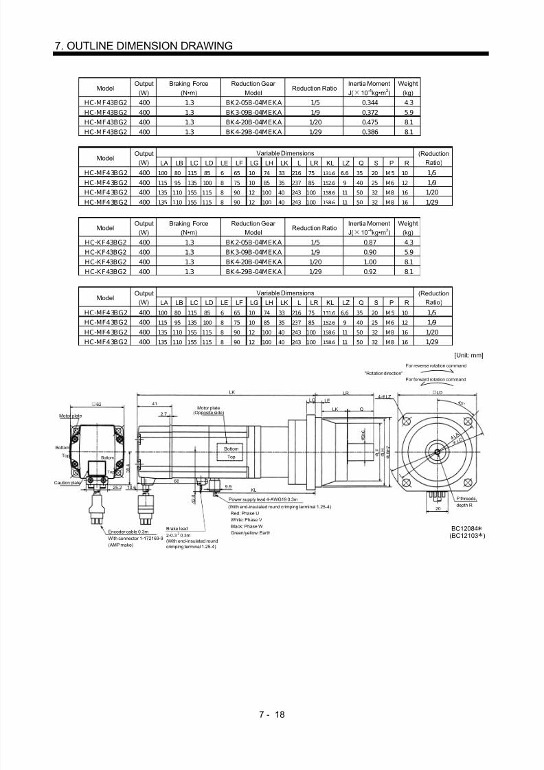
8/10/2019 Servo Motor - Instruction Manual SH(NA)-3181-D (03.00)
http://slidepdf.com/reader/full/servo-motor-instruction-manual-shna-3181-d-0300 97/368
7 - 18
7. OUTLINE DIMENSION DRAWING
ModelOutput
(W)Braking Force
(N•m)Reduction Gear
ModelReduction Ratio
Inertia MomentJ( 10 -4kg•m 2)
Weight(kg)
HC-MF43BG2 400 1.3 BK2-05B-04MEKA 1/5 0.344 4.3HC-MF43BG2 400 1.3 BK3-09B-04MEKA 1/9 0.372 5.9HC-MF43BG2 400 1.3 BK4-20B-04MEKA 1/20 0.475 8.1
HC-MF43BG2 400 1.3 BK4-29B-04MEKA 1/29 0.386 8.1
Variable DimensionsModel
Output(W) LA LB LC LD LE LF LG LH LK L LR KL LZ Q S P R
(ReductionRatio)
HC-MF43BG2 400 100 80 115 85 6 65 10 74 33 216 75 131.6 6.6 35 20 M 5 10 1/5HC-MF43BG2 400 115 95 135 100 8 75 10 85 35 237 85 152.6 9 40 25 M6 12 1/9HC-MF43BG2 400 135 110 155 115 8 90 12 100 40 243 100 158.6 11 50 32 M8 16 1/20HC-MF43BG2 400 135 110 155 115 8 90 12 100 40 243 100 158.6 11 50 32 M8 16 1/29
ModelOutput
(W)Braking Force
(N•m)Reduction Gear
ModelReduction Ratio
Inertia MomentJ( 10 -4kg•m 2)
Weight(kg)
HC-KF43BG2 400 1.3 BK2-05B-04MEKA 1/5 0.87 4.3HC-KF43BG2 400 1.3 BK3-09B-04MEKA 1/9 0.90 5.9HC-KF43BG2 400 1.3 BK4-20B-04MEKA 1/20 1.00 8.1
HC-KF43BG2 400 1.3 BK4-29B-04MEKA 1/29 0.92 8.1
Variable DimensionsModel
Output(W) LA LB LC LD LE LF LG LH LK L LR KL LZ Q S P R
(ReductionRatio)
HC-MF43BG2 400 100 80 115 85 6 65 10 74 33 216 75 131.6 6.6 35 20 M 5 10 1/5HC-MF43BG2 400 115 95 135 100 8 75 10 85 35 237 85 152.6 9 40 25 M6 12 1/9HC-MF43BG2 400 135 110 155 115 8 90 12 100 40 243 100 158.6 11 50 32 M8 16 1/20HC-MF43BG2 400 135 110 155 115 8 90 12 100 40 243 100 158.6 11 50 32 M8 16 1/29
LELG
LK LR
Q
4 5 °
With connector 1-172169-9(AMP make)
Motor plate
Bottom
Top
Power supply lead 4-AWG19 0.3m
(With end-insulated round crimping terminal 1.25-4) Red: Phase U White: Phase V Black: Phase W Green/yellow: EarthEncoder cable 0.3m
P threads,depth R
For forward rotation command"Rotation direction"
For reverse rotation command
Brake lead2-0.3 0.3m(With end-insulated roundcrimping terminal 1.25-4)
2
S h 6
L F L H
L B h 7
L C L A
4- LZLD
(BC12103 )BC12084
20
Bottom
Top
Caution plate
LK62 41
2.7Motor plate
(Opposite side)
Bottom
Top
KL9.9
6825.2
3 8 . 4
10.6
4 2 . 8
[Unit: mm]

8/10/2019 Servo Motor - Instruction Manual SH(NA)-3181-D (03.00)
http://slidepdf.com/reader/full/servo-motor-instruction-manual-shna-3181-d-0300 98/368
7 - 19
7. OUTLINE DIMENSION DRAWING
ModelOutput
(W)Braking Force
(N•m)Reduction Gear
ModelReduction Ratio
Inertia MomentJ( 10 -4kg•m 2)
Weight(kg)
HC-MF73BG2 750 2.4 BK3-05B-08MEKA 1/5 1.098 7.3HC-MF73BG2 750 2.4 BK4-09B-08MEKA 1/9 1.105 9.6HC-MF73BG2 750 2.4 BK5-20B-08MEKA 1/20 1.141 13.0
HC-MF73BG2 750 2.4 BK5-29B-08MEKA 1/29 1.035 13.0
Variable DimensionsModel
Output(W) LA LB LC LD LE LF LG LH LK L LR KL LZ Q S P R
(ReductionRatio)
HC-MF73BG2 750 115 95 135 100 8 75 10 85 35 247.5 85 156.7 9 40 25 M6 12 1/5HC-MF73BG2 750 135 110 155 115 8 90 12 100 40 283.5 100 192.7 11 50 32 M8 16 1/9HC-MF73BG2 750 150 125 175 130 10 105 15 115 43 283.5 115 192.7 14 60 40 M10 20 1/20HC-MF73BG2 750 150 125 175 130 10 105 15 115 43 283.5 115 192.7 14 60 40 M10 20 1/29
Motor plate(Opposite side)
LELG4- LZ
Top
Bottom
LK
LR
Q
"Rotation direction"For forward rotation command
For reverse rotation command
Power supply lead 4-AWG19 0.3m (With end-insulated round crimping terminal 1.25-4)
Brake lead2-0.3 0.3m(With end-insulated round
crimping terminal 1.25-4)
2
Encoder cable 0.3mWith connector 1-172169-9(AMP make)
Red: Phase UWhite: Phase VBlack: Phase WGreen/yellow: Earth
4 5 °
P threads,depth R
S h 6
L F L H
L B h 7
L
Motor plate82
Caution plate 25.2
4 8 . 7
Top
Bottom
Top
Bottom
39
2.7
1172
9.9 KL
LD
BC12085
5 8 . 1
L A
L C
[Unit: mm]

8/10/2019 Servo Motor - Instruction Manual SH(NA)-3181-D (03.00)
http://slidepdf.com/reader/full/servo-motor-instruction-manual-shna-3181-d-0300 99/368
7 - 20
7. OUTLINE DIMENSION DRAWING
(5) HC-MF-UE•HC-KF-UE series(a) Standard (without electromagnetic brake, without reduction gear)
Variable DimensionsModel
Output(W) L KL
Inertia MomentJ( 10 -4kg•m 2)
Weight(kg)
HC-MF053-UE 50 89.5 37.5 0.019 0.5HC-MF13-UE 100 104.5 52.5 0.03 0.6HC-KF053-UE 50 89.5 37.5 0.054 0.5HC-KF13-UE 100 104.5 52.5 0.085 0.53
Motor plate
Caution plate
Bottom
Top
Bottom
Top
25.2
2 8 . 7
42
Encoder cable0.3m
Encoder cable 0.3mWith connector 1-172169-9(AMP make)
Power supply lead 4-AWG19 0.3m(With end-insulated round crimping terminal 1.25-4)
Red: Phase UWhite: Phase VBlack: Phase WGreen/yellow: Earth
Motor plate(Opposite side)
Bottom
Top
Bottom
Top
40.5
L 25
5 2.5
KLTUV plate
8 h 6
3 0 h 7
V-10A
2- 4.5
4 5 °
40
4 6
3 5 . 7
20
BC07328A
9.96.8
V ring
[Unit: mm]
Variable DimensionsModel
Output(W) L KL
Inertia MomentJ( 10 -4kg•m 2)
Weight(kg)
HC-MF23-UE 200 108.5 58 0.09 1.2HC-MF43-UE 400 133.5 81 0.14 1.7
HC-KF23-UE 200 108.5 58 0.43 1.2HC-KF43-UE 400 133.5 81 0.68 1.7
62
Motor plate
Caution plate
25.2
3 8 . 4
plate
Bottom
Top
Bottom
Top
Bottom
Top
10.69.9
41
2.7
L 30
37Motor plate
(Opposite side)
Bottom
Top
KL
V ring
V-16A
Encoder cable 0.3mWith connector 1-172169-9(AMP make)
Power supply lead 4-AWG19 0.3m(With end-insulated round crimping terminal 1.25-4)
Red: Phase UWhite: Phase VBlack: Phase WGreen/yellow: Earth
20
BC07329A
4 2 . 8
7 0
4 5 °4- 5.8
30
1 4 h 6
5 0 h 7
TUV
[Unit: mm]

8/10/2019 Servo Motor - Instruction Manual SH(NA)-3181-D (03.00)
http://slidepdf.com/reader/full/servo-motor-instruction-manual-shna-3181-d-0300 100/368

8/10/2019 Servo Motor - Instruction Manual SH(NA)-3181-D (03.00)
http://slidepdf.com/reader/full/servo-motor-instruction-manual-shna-3181-d-0300 101/368
7 - 22
7. OUTLINE DIMENSION DRAWING
Variable DimensionsModel
Output(W) L KL
Braking Force(N•m)
Inertia MomentJ( 10 -4kg•m 2)
Weight(kg)
HC-MF23B-UE 200 140.5 58 0.136 1.7HC-MF43B-UE 400 165.5 81 0.191 2.2HC-KF23B-UE 200 140.5 58 0.48 1.7
HC-K F43B-UE 400 165.5 81
1.3
0.73 2.2
Encoder cable 0.3mWith connector 1-172169-9(AMP make)
Brake lead2-0.3 0.3m(With end-insulated round crimping terminal 1.25-4)B1,B2
Power supply lead 4-AWG19 0.3m(With end-insulated round crimping terminal 1.25-4)
Red: Phase UWhite: Phase VBlack: Phase WGreen/yellow: Earth
Motor plate(Opposite side)
Bottom
Top
Motor plate
Caution plate
Top
Bottom
Bottom
Top
Top
Bottom
25.2
3 8 . 4
TUV plate
10.6
41
2.7
L 30
37
95
9.9
1 4 h 6 5 0 h 7
V-16A
60
4- 5.8 4 5 °
4 2 . 8
20
BC07354A
V ring
62
7 0
[Unit: mm]
2
ModelOutput
(W)Braking Force (N•m)
Inertia MomentJ( 10 -4kg•m 2)
Weight(kg)
HC-MF73B-UE 750 2.4 0.75 4.2
Encoder cable 0.3mWith connector 1-172169-9(AMP make)
Brake lead2-0.3 0.3m(With end-insulated round
crimping terminal 1.25-4)B1,B2
Power supply lead 4-AWG19 0.3m(With end-insulated round crimping terminal 1.25-4)
Red: Phase UWhite: Phase VBlack: Phase W
Green/yellow: Earth
BC07606A
20
5 8 . 1
9 0
4- 6.6
80
4 5 °
40
38
1 9 h 6
7 0 h 7
95
9.9V-25A
Bottom
Top
Motor plate
Caution plate 25.2
4 8 . 7
plateTUV
Bottom
Top
Bottom
Top
39
2.7
Motor plate(Opposite side)
185.5
11 V ring
82
2
[Unit: mm]

8/10/2019 Servo Motor - Instruction Manual SH(NA)-3181-D (03.00)
http://slidepdf.com/reader/full/servo-motor-instruction-manual-shna-3181-d-0300 102/368
7 - 23
7. OUTLINE DIMENSION DRAWING
7.1.2 HA-FF series
(1) Standard (without electromagnetic brake, without reduction gear)
ModelOutput
(W)Variable Dimensions
LInertia MomentJ( 10 -4kg•m 2)
Weight(kg)
HA-FF053 50 106 0.063 1.3HA-FF13 100 123 0.095 1.5
[Unit: mm]
Motor plate
39 2.56
8 h 6
54
4- 4.5
Bottom
Z694731
5 0 h 7
30
BottomTop
3 9
Caution plate
L
Earth terminal M3 screw(Opposite side)
V ring 3 9
4 7
Top
Power supply cableVCTF 3-1.25 0.5m(With end-insulated round crimping terminal 1.25-4)
Encoder cable 0.3mWith connector 172169-9(AMP make)
2
Red: Phase UWhite: Phase VBlack: Phase W
4 5 °
6 0
6 8
ModelOutput
(W)Variable Dimensions
LInertia MomentJ( 10 -4kg•m 2)
Weight(kg)
HA-FF23 200 130.5 0.35 2.3HA-FF33 300 148 0.5 2.6
Motor plate
39 38
76
4- 5.5
[Unit: mm]
Bottom
Z694732
7 0 h 7
30
BottomTop
3 9
Caution plate
L
V ring 5 0
4 7
Earth terminal M3 screw
A
A
16 4
25
M4 0.7 threads,depth 15
4
Section AA
2 . 5
4
1 0 0 9 0
11h6
Power supply cableVCTF 3-1.25 0.5m(With end-insulated round crimping terminal 1.25-4)
2
Encoder cable 0.3mWith connector 172169-9(AMP make)
Top
Red: Phase UWhite: Phase VBlack: Phase W
4 5 °

8/10/2019 Servo Motor - Instruction Manual SH(NA)-3181-D (03.00)
http://slidepdf.com/reader/full/servo-motor-instruction-manual-shna-3181-d-0300 103/368
7 - 24
7. OUTLINE DIMENSION DRAWING
ModelOutput
(W)Variable Dimensions
LInertia MomentJ( 10 -4kg•m 2)
Weight(kg)
HA-FF43 400 154.5 0.975 4.2HA-FF63 600 169.5 12 4.8
Motor plate
39 310
100
4- 9
[Unit: mm]
Z694733
9 5 h 7
40
3 9
L
V ring 6 2
4 7
Caution plate
A
A
5
35
5
Section AA
3 5
16h6
25
1 3 5
BottomTop
M5 0.8 threads,depth 20
Power supply cableVCTF 3-1.25 0.5m
(With end-insulated round crimping terminal 1.25-4)
2
Red: Phase UWhite: Phase VBlack: Phase W
Encoder cable 0.3mWith connector 172169-9(AMP make)
Earth terminal M3 screw
Bottom
Top
4 5 °
1 1 5
(2) Without electromagnetic brake
ModelOutput
(W)Variable Dimensions
LBraking Force
(N•m)Inertia MomentJ( 10 -4kg•m 2)
Weight(kg)
HA-FF053B 50 141 0.39 0.08 1.6HA-FF13B 100 158 0.39 0.113 1.8
Motor plate
39 2.56
8 h 6
54
4- 4.5
[Unit: mm]
Top
Bottom
Z694734
5 0 h 7
30
BottomTop
3 9
Caution plate
LEarth terminal M3 screw(Opposite side)
V ring 3 9
4 7
6 06 8
Power supply cableVCTF 3-1.25 0.5m(With end-insulated round crimping terminal 1.25-4)
2
Red: Phase UWhite: Phase VBlack: Phase W
Encoder cable 0.3mWith connector 172169-9(AMP make)
Brake leadVCTF 2-0.5 0.5m(With end-insulated round crimping terminal 1.25-4)
2
4 5 °
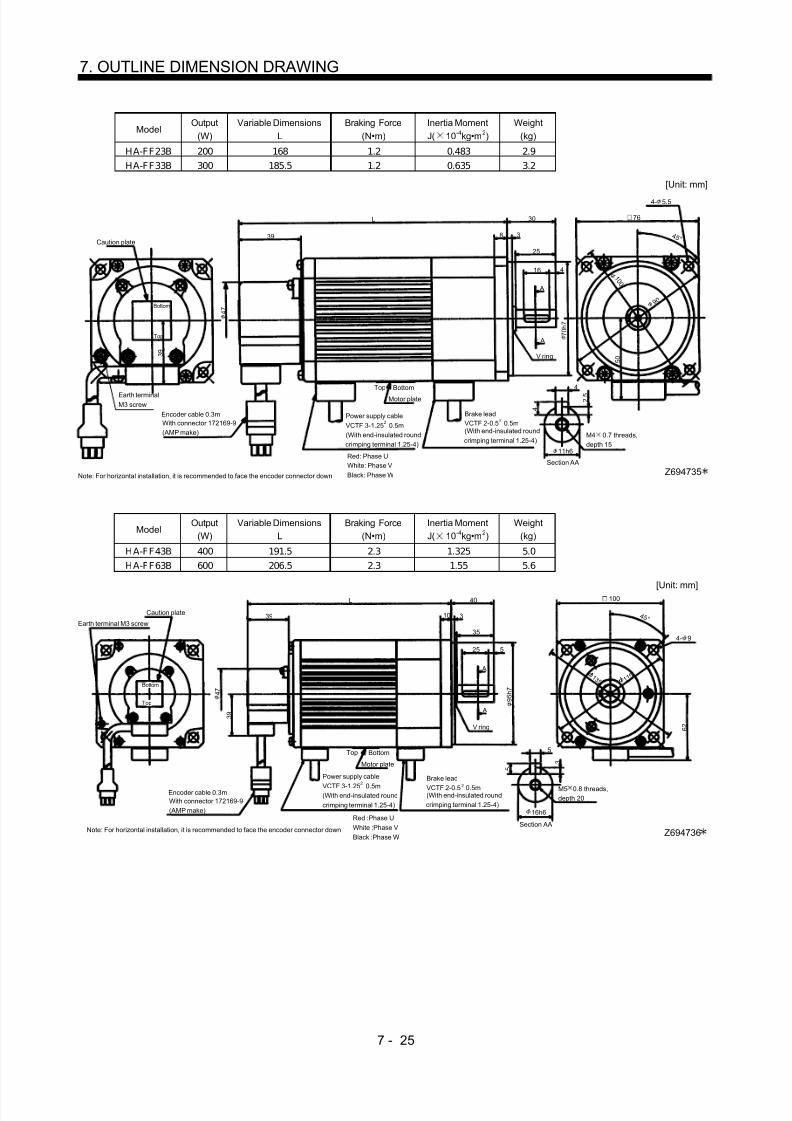
8/10/2019 Servo Motor - Instruction Manual SH(NA)-3181-D (03.00)
http://slidepdf.com/reader/full/servo-motor-instruction-manual-shna-3181-d-0300 104/368
7 - 25
7. OUTLINE DIMENSION DRAWING
ModelOutput
(W)Variable Dimensions
LBraking Force
(N•m)Inertia MomentJ( 10 -4kg•m 2)
Weight(kg)
HA-FF23B 200 168 1.2 0.483 2.9HA-FF33B 300 185.5 1.2 0.635 3.2
Motor plate
39 38
76
4- 5.5
[Unit: mm]
Top
Bottom
Note: For horizontal installation, it is recommended to face the encoder connector down Z694735
7 0 h 7
30
4 5 °
BottomTop
3 9
Caution plate
L
V ring 5 0
4 7
A
A
4
25
4
Section AA
2 . 5
4
11h6
161 0 0
Earth terminalM3 screw
M4 0.7 threads,depth 15
Power supply cableVCTF 3-1.25 0.5m(With end-insulated round crimping terminal 1.25-4)
2
Red: Phase UWhite: Phase VBlack: Phase W
Encoder cable 0.3mWith connector 172169-9(AMP make)
Brake leadVCTF 2-0.5 0.5m(With end-insulated round crimping terminal 1.25-4)
2
9 0
ModelOutput
(W)Variable Dimensions
LBraking Force
(N•m)Inertia MomentJ( 10 -4kg•m 2)
Weight(kg)
HA-FF43B 400 191.5 2.3 1.325 5.0HA-FF63B 600 206.5 2.3 1.55 5.6
Motor plate
39 310
100
4- 9
[Unit: mm]
Note: For horizontal installation, it is recommended to face the encoder connector down Z694736
9 5 h 7
40
4 5 °
BottomTop
3 9
Caution plate
L
V ring 6 2
4 7
Earth terminal M3 screw
A
A
5
35
M5 0.8 threads,depth 20
5
Section AA
3 5
16h6
25
Power supply cable
VCTF 3-1.25 0.5m(With end-insulated roundcrimping terminal 1.25-4)
2
Red :Phase UWhite :Phase VBlack :Phase W
Encoder cable 0.3mWith connector 172169-9(AMP make)
Brake leadVCTF 2-0.5 0.5m(With end-insulated round crimping terminal 1.25-4)
2
Top
Bottom 1 1
51 3 5

8/10/2019 Servo Motor - Instruction Manual SH(NA)-3181-D (03.00)
http://slidepdf.com/reader/full/servo-motor-instruction-manual-shna-3181-d-0300 105/368
7 - 26
7. OUTLINE DIMENSION DRAWING
(3) With reduction gear for general industrial machine(a) Without electromagnetic brake
ModelOutput
(W)Reduction
Gear ModelReduction Ratio
(Actual Reduction Ratio)Inertia MomentJ( 10 -4kg•m 2)
BacklashWeight
(kg)Output Shaft
Rotation Direction
1/5(9/44)1/10(3/29) 0.068
Same as that of motor shaft
1/20(99/1972)HC-FF053G1 50 GR-S-10
1/30(144/4205 0.063
40min. to1.5
˚ 2.5Opposite to that of
motor shaft
39
3
33
90
4- 6.5 (Note)
Top
Bottom
Note: Four M6 90 through bolts are provided. Z694764
3 4
BottomTop
3 9
Caution plate
183
9 0
4 7
A
A
5
Section AA
3 5
15h6
106
Earth terminal M3 screw(Opposite side)
77
27.5
38
1 8
1 0 4
[Unit: mm]"Rotation direction"
For forward rotation command
For reverse rotation command
Power supply cable VCTF 3-1.25 0.5m(With end-insulated round crimping terminal 1.25-4)
Red: Phase UWhite: Phase VBlack: Phase WEncoder cable 0.3m
With connector 172169-9(AMP make)
4 5 °
2
Model Output(W)
ReductionGear Model
Reduction Ratio(Actual Reduction Ratio)
Inertia MomentJ( 10 -4kg•m 2)
Backlash Weight(kg)
Output ShaftRotation Direction
1/5(9/44)1/10(3/29)
0.10 Same as that of
motor shaft1/20(25/1972)
HC-FF13G1 100 GR-S-10
1/30(25/4205)0.095
40min. to1.5
˚ 2.7Opposite to that of
motor shaft
Caution plate
Motor plate
39
3
33
90
4- 6.5 (Note)
Top
Bottom
Z694765
3 4
2
BottomTop
3 9
200
9 0 4 7 A
A
5
Section AA
3 5
15h6
123
Earth terminal M3 screw(Opposite side)
77
27.5
38
1 8
1 0 4
[Unit: mm]"Rotation direction"
For forward rotation command
For reverse rotation command
Power supply cableVCTF 3-1.25 0.5m(With end-insulated round crimping terminal 1.25-4)
Red: Phase UWhite: Phase VBlack: Phase W
Encoder cable 0.3mWith connector 172169-9(AMP make)
Note: Four M6 90 through bolts are provided.
4 5 °

8/10/2019 Servo Motor - Instruction Manual SH(NA)-3181-D (03.00)
http://slidepdf.com/reader/full/servo-motor-instruction-manual-shna-3181-d-0300 106/368
7 - 27
7. OUTLINE DIMENSION DRAWING
ModelOutput
(W)Reduction
Gear ModelReduction Ratio
(Actual Reduction Ratio)Inertia MomentJ( 10 -4kg•m 2)
BacklashWeight
(kg)Output Shaft
Rotation Direction
1/5(57/280)1/10(39/400)
0.373
1/20(51/980)HC-FF23G1 200 GR-S-20
1/30(1/30)
0.37
40min. to1.5
˚ 5.0 Same as that of
motor shaft
Motor plate
39 3
25
145
4- 10
Top
Bottom
Z694766
1 3 0 j s 7
3 9
Caution plate
214.5
1 5 0
A
A
5
Section AA
3 5
16h6
130.5
32.5
24
12
1 5
4 7
84
7 7 . 5
7 2 . 5
1 8 0
[Unit: mm]"Rotation direction"
For forward rotation command
For reverse rotation command
M6 threads,depth 10
Bottom
Top
Power supply cable VCTF 3-1.25 0.5m(With end-insulated round crimping terminal 1.25-4)
Red: Phase UWhite: Phase VBlack: Phase W
Encoder cable 0.3mWith connector 172169-9(AMP make)
Earth terminal M3 screw(Opposite side)
2
4 5 °
ModelOutput
(W)Reduction
Gear ModelReduction Ratio
(Actual Reduction Ratio)Inertia MomentJ( 10 -4kg•m 2)
BacklashWeight
(kg)Output Shaft
Rotation Direction
1/5(19/94)1/10(39/376)
0.545
1/20(72/1303)HC-FF33G1 300 GR-S-30
1/30(11/329)0.538
40min. to1.5
˚ 6.5 Same as that of
motor shaft
Motor plate
39 3
25
1454- 10
Top
Bottom
Z694767
1 3 0 j s 7
BottomTop
3 9
Caution plate
250
1 6 0
A
A
6
Section AA
3 . 5
6
19h6
148
37.5
28
12
1 8
4 7
102
M6 threads,depth 10
8 7 . 5
7 2 . 5
[Unit: mm]"Rotation direction"
For forward rotation command
For reverse rotation command
Power supply cable VCTF 3-1.25 0.5m(With end-insulated round crimping terminal 1.25-4)
Red: Phase UWhite: Phase VBlack: Phase W
Encoder cable 0.3mWith connector 172169-9(AMP make)
2
Earth terminal M3 screw(Opposite side)
4 5 °
1 8 0

8/10/2019 Servo Motor - Instruction Manual SH(NA)-3181-D (03.00)
http://slidepdf.com/reader/full/servo-motor-instruction-manual-shna-3181-d-0300 107/368
7 - 28
7. OUTLINE DIMENSION DRAWING
ModelOutput
(W)Reduction
Gear ModelReduction Ratio
(Actual Reduction Ratio)Inertia MomentJ( 10 -4kg•m 2)
BacklashWeight
(kg)Output Shaft
Rotation Direction
1/5(19/94)1/10(39/376)
1.02
1/20(72/1363)HC-FF43G1 400 GR-S-40
1/30(11/329)
1.01
40min. to1.5
˚ 8.0 Same as that of
motor shaft
Motor plate
39 3
25
145 4- 10
Top
Bottom
Z694768
1 3 0 j s 7
BottomTop
3 9
Caution plate
258.5
1 6 0
A
A
6
Section AA
3 . 5
6
19h6
154.5
37.5
28
12
1 8 4 7
104
M6 threads,depth 10
8 7 . 5
7 2 . 5
1 8 0
[Unit: mm]"Rotation direction"
For forward rotation command
For reverse rotation command
2Power supply cable VCTF 3-1.25 0.5m(With end-insulated round crimping terminal 1.25-4)
Red: Phase UWhite: Phase VBlack: Phase W
Encoder cable 0.3mWith connector 172169-9(AMP make)
Earth terminal M3 screw(Opposite side)
ModelOutput
(W)Reduction
Gear ModelReduction Ratio
(Actual Reduction Ratio)Inertia MomentJ( 10 -4kg•m 2)
BacklashWeight
(kg)Output Shaft
Rotation Direction
1/5(10/49)1/10(243/2401)
1.34
1/20(153/2891)HC-FF63G1 600 GR-S-60
1/30(27/784) 1.32
40min. to1.5
˚ 13.0 Same as that of
motor shaft
39 3
32
185
2 2 5
Top
Bottom
Z694769
1 7 0 j s 7
3 9
Caution plate
274.5
1 9 2 . 5
A
A
6
Section AA
3 . 5
6
22h6
169.5
46.5
36
12
2 0 4 7
105
M8 threads,depth 12
1 0 0
9 2 . 5
4- 12
[Unit: mm]"Rotation direction"
For forward rotation command
For reverse rotation command
Motor plateBottomTop
2Power supply cable VCTF 3-1.25 0.5m(With end-insulated round crimping terminal 1.25-4)
Red: Phase UWhite: Phase VBlack: Phase W
Encoder cable 0.3mWith connector 172169-9(AMP make)
Earth terminal M3 screw(Opposite side)
4 5 °

8/10/2019 Servo Motor - Instruction Manual SH(NA)-3181-D (03.00)
http://slidepdf.com/reader/full/servo-motor-instruction-manual-shna-3181-d-0300 108/368
7 - 29
7. OUTLINE DIMENSION DRAWING
(b) With electromagnetic brake
ModelOutput
(W)Braking Force
(N•m)Reduction
Gear ModelReduction Ratio
(Actual Reduction Ratio)Inertia MomentJ( 10 -4kg•m 2)
BacklashWeight
(kg)Output Shaft
Rotation Direction
1/5(9/44)1/10(3/29)
0.085Same as that of
motor shaft
1/20(99/1972)H A-F F053BG1 50 0.39 GR-S-101/30(144/4205)
0.080
40min.to 1.5 ˚ 2.8 Opposite to that of
motor shaft
Motor plate
39
314190
4- 6.5 (Note)
Top
Bottom
Z694770
3 4
38
Bottom
3 9
Caution plate
218
9 0 4 7
Earth terminal M3 screw(Opposite side)
A
A
33
5
Section AA
3 5
15h6
27.5
Brake cableVCTF 2-0.5 0.5m(With end-insulated round crimping terminal 1.25-4)
2
77
1 8
1 0 4
[Unit: mm]"Rotation direction"
For forward rotation command
For reverse rotation command
Top
Power supply cable VCTF 3-1.25 0.5m(With end-insulated round crimping terminal 1.25-4)
Red: Phase UWhite: Phase VBlack: Phase W
Encoder cable 0.3mWith connector 172169-9(AMP make)
Note: Four M6 90 through bolts are provided.
2
4 5 °
ModelOutput
(W)Braking Force
(N•m)Reduction
Gear ModelReduction Ratio
(Actual Reduction Ratio)Inertia MomentJ( 10 -4kg•m 2)
BacklashWeight
(kg)Output Shaft
Rotation Direction
1/5(9/44)
1/10(3/29)0.115
Same as that of
motor shaft1/20(99/1972)
H A-F F13BG1 100 0.39 GR-S-10
1/30(144/4205)0.11
40min.to 1.5
˚ 3.0Opposite to that of
motor shaft
39
315890 4- 6.5 (Note)
Top
Bottom
Z694771
3 4
38
3 9
Caution plate
235
9 0 4 7
Earth terminal M3 screw(Opposite side)
A
A
33
5
Section AA
3 5
15h6
27.5
2
77
1 8
1 0 4
Note: Four M6 90 through bolts are provided.
[Unit: mm]"Rotation direction"
For forward rotation command
For reverse rotation command
Encoder cable 0.3mWith connector 172169-9(AMP make)
Power supply cable VCTF 3-1.25 0.5m(With end-insulated round crimping terminal 1.25-4)Red: Phase UWhite: Phase VBlack: Phase W
Brake cableVCTF 2-0.5 0.5m(With end-insulated round crimping terminal 1.25-4)
2
Motor plateBottom
Top
4 5 °
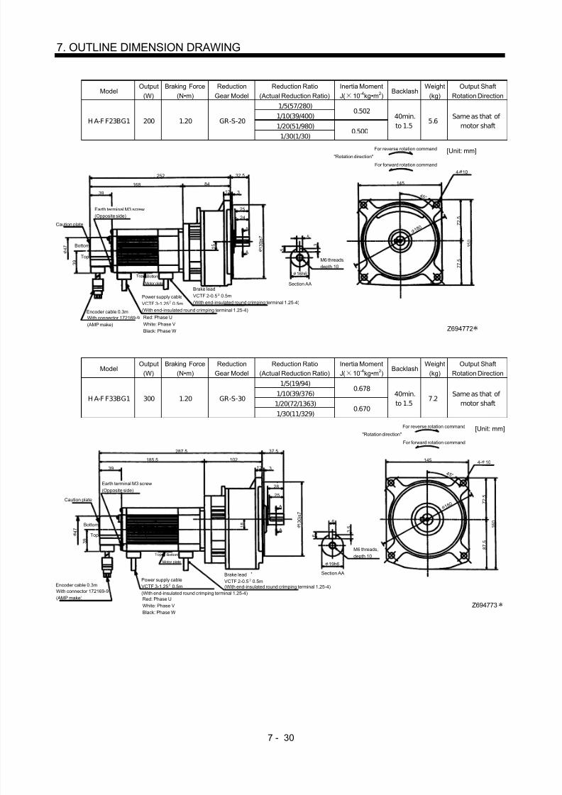
8/10/2019 Servo Motor - Instruction Manual SH(NA)-3181-D (03.00)
http://slidepdf.com/reader/full/servo-motor-instruction-manual-shna-3181-d-0300 109/368
7 - 30
7. OUTLINE DIMENSION DRAWING
ModelOutput
(W)Braking Force
(N•m)Reduction
Gear ModelReduction Ratio
(Actual Reduction Ratio)Inertia MomentJ( 10 -4kg•m 2)
BacklashWeight
(kg)Output Shaft
Rotation Direction
1/5(57/280)1/10(39/400)
0.502
1/20(51/980)H A-F F23BG1 200 1.20 GR-S-20
1/30(1/30)
0.500
40min.to 1.5
˚ 5.6 Same as that of
motor shaft
Motor plate
39 3
25
145
4- 10
Top
Bottom 1 3 0 j s 7
Power supply cableVCTF 3-1.25 0.5m(With end-insulated round crimping terminal 1.25-4)
2
BottomTop
3 9
Caution plate
252
1 5 0
A
A
5
Section AA
3 5
168
32.5
24
12
1 5 4 7
84
7 7 . 5
7 2 . 5
1 8 0
Brake leadVCTF 2-0.5 0.5m(With end-insulated round crimping terminal 1.25-4)
2
[Unit: mm]"Rotation direction"
For forward rotation command
For reverse rotation command
M6 threads,depth 10
Red: Phase UWhite: Phase VBlack: Phase W
Encoder cable 0.3mWith connector 172169-9(AMP make)
Earth terminal M3 screw(Opposite side)
4 5 °
Z694772
16h6
ModelOutput
(W)Braking Force
(N•m)Reduction
Gear ModelReduction Ratio
(Actual Reduction Ratio)Inertia MomentJ( 10 -4kg•m 2)
BacklashWeight
(kg)Output Shaft
Rotation Direction
1/5(19/94)1/10(39/376)
0.678
1/20(72/1363)H A-F F33BG1 300 1.20 GR-S-30
1/30(11/329)0.670
40min.to 1.5
˚ 7.2 Same as that of
motor shaft
39 3
28
145 4- 10
Red: Phase UWhite: Phase VBlack: Phase W
Top
Bottom
Z694773
1 3 0 j s 7
3 9
Caution plate
287.5
1 6 0
A
A
6
Section AA
3 . 5
6
19h6
185.5
37.5
25
12
1 8
4 7
102
M6 threads,
depth 10
8 7 . 5
7 2 . 5
1 8 0
[Unit: mm]"Rotation direction"
For forward rotation command
For reverse rotation command
Brake leadVCTF 2-0.5 0.5m(With end-insulated round crimping terminal 1.25-4)
2
Motor plate
BottomTop
Power supply cableVCTF 3-1.25 0.5m(With end-insulated round crimping terminal 1.25-4)
2Encoder cable 0.3mWith connector 172169-9(AMP make)
Earth terminal M3 screw(Opposite side)
4 5 °

8/10/2019 Servo Motor - Instruction Manual SH(NA)-3181-D (03.00)
http://slidepdf.com/reader/full/servo-motor-instruction-manual-shna-3181-d-0300 110/368
7 - 31
7. OUTLINE DIMENSION DRAWING
ModelOutput
(W)Braking Force
(N•m)Reduction
Gear ModelReduction Ratio
(Actual Reduction Ratio)Inertia MomentJ( 10 -4kg•m 2)
BacklashWeight
(kg)Output Shaft
Rotation Direction
1/5(19/94)1/10(39/376)
1.37
1/20(72/1363)H A-F F43BG1 400 2.30 GR-S-40
1/30(11/329)
1.36
40min.to 1.5
˚ 8.9 Same as that of
motor shaft
39 3
28
1454- 10
Red: Phase UWhite: Phase VBlack: Phase W
Top
Bottom
Z694774
1 3 0 j s 7
3 9
Caution plate
295.5
1 6 0
A
A
6
Section AA
3 . 5
6
191.5
37.5
25
12
1 8 4 7
104
M6 threads,depth 10 8 7 .
5
7 2 . 5
1 8 0
2
[Unit: mm]"Rotation direction"
For forward rotation command
For reverse rotation command
Brake leadVCTF 2-0.5 0.5m(With end-insulated round crimping terminal 1.25-4)
Motor plateBottomTop
Power supply cableVCTF 3-1.25 0.5m(With end-insulated round crimping terminal 1.25-4)
2Encoder cable 0.3mWith connector 172169-9(AMP make)
Earth terminal M3 screw(Opposite side)
4 5 °
19h6
ModelOutput
(W)Braking Force
(N•m)Reduction
Gear ModelReduction Ratio
(Actual Reduction Ratio)Inertia MomentJ( 10 -4kg•m 2)
BacklashWeight
(kg)Output Shaft
Rotation Direction
1/5(10/49)1/10(243/2401)
1.69
1/20(153/2891)H A-F F63BG1 600 2.30 GR-S-60
1/30(27/784) 1.67
40min.to 1.5
˚ 13.9 Same as that of
motor shaft
39
3
36
185 4- 12
Top
Bottom
Z694775
1 7 0 j s 7
Power supply cableVCTF 3-1.25 0.5m(With end-insulated round crimping terminal 1.25-4)
2
3 9
Caution plate
311.5
1 9 2 . 5
A
A 6
3 . 5
6
22h6
206.5
Earth terminal M3 screw(Opposite side)
46.5
32
12
2 0 4 7
105
1 0 0
9 2 . 5
2 2 5
2
Brake leadVCTF 2-0.5 0.5m(With end-insulated round crimping terminal 1.25-4)
Motor plateBottomTop
Encoder cable 0.3mWith connector 172169-9(AMP make)
Red: Phase UWhite: Phase VBlack: Phase W
Section AA
M8 threads,depth 12
[Unit: mm]"Rotation direction"
For forward rotation command
For reverse rotation command
4 5 °

8/10/2019 Servo Motor - Instruction Manual SH(NA)-3181-D (03.00)
http://slidepdf.com/reader/full/servo-motor-instruction-manual-shna-3181-d-0300 111/368
7 - 32
7. OUTLINE DIMENSION DRAWING
(4) With reduction gear for precision application(a) Without electromagnetic brake
ModelOutput
(W)Reduction Gear
ModelReduction Ratio
Inertia MomentJ( 10 -4kg•m 2)
BacklashWeight
(kg)
HA-FF053G2 50 BM2-05B-A5MES 1/5 0.11 3 min. max. 2.3
Motor plate
39
6
99
4- 4.5
30
BottomTop
3 9
Caution Plate
205
Earth terminalM3 screw(Opposite side)
4 7
Earth terminal M3
2
9 20
7 8 7 5
[Unit: mm]"Rotation direction"
For forward rotation command
For reverse rotation command
Power supply cableVCTF 3-1.25 0.5m(With end-insulated round crimping terminal 1.25-4)
2
Red: Phase UWhite: Phase VBlack: Phase W
Encoder cable 0.3mWith connector 172169-9(AMP make)
Bottom
Top
1 0 h 6
4 5 °
74
Z694850
3 3 6 2 h 7
8 9
ModelOutput
(W)Variable dimensions L
Reduction Gear Model
Reduction RatioInertia MomentJ( 10 -4kg•m 2)
BacklashWeight
(kg)
HA-FF053G2 50 205 BM2-10B-A5MES 1/10 0.108 3 min. max. 2.3HA-FF053G2 50 205 BM2-15B-A5MES 1/15 0.105 3 min. max. 2.3HA-FF053G2 100 205 BM2-05B-01MES 1/5 0.143 3 min. max. 2.5
Motor plate
39
6
99
74
4- 4.5
Z694805
6 2 h 7
30
BottomTop
3 9
Caution plate
L
Earth terminalM3 screw(Opposite side)
4 7
Earth terminal M3
2
9 20
3 3
7 88 9 7 5
[Unit: mm]"Rotation direction"
For forward rotation command
For reverse rotation command
Power supply cableVCTF 3-1.25 0.5m(With end-insulated round crimping terminal 1.25-4)
2
Red: Phase UWhite: Phase VBlack: Phase W
Encoder cable 0.3mWith connector 172169-9(AMP make)
Top
Bottom 1 0 h 6
4 5 °

8/10/2019 Servo Motor - Instruction Manual SH(NA)-3181-D (03.00)
http://slidepdf.com/reader/full/servo-motor-instruction-manual-shna-3181-d-0300 112/368
7 - 33
7. OUTLINE DIMENSION DRAWING
ModelOutput
(W)Variable dimensions L
Reduction Gear Model
Reduction RatioInertia MomentJ( 10 -4kg•m 2)
BacklashWeight
(kg)
HA-FF053G2 50 213 BM3-25B-A5MES 1/25 0.110 3min. max. 2.8HA-FF13G2 100 230 BM3-10B-01MES 1/10 0.165 3min. max. 3.0HA-FF13G2 100 230 BM3-15B-01MES 1/15 0.155 3min. max. 3.0
Motor plate
39
8
107
87
4- 5.5
Z694806
35
BottomTop
3 9
Caution plate
L
Earth terminalM3 screw(Opposite side)
4 7
Earth terminal M3
2
9 25
8 7 9 0
[Unit: mm]"Rotation direction"
For forward rotation command
For reverse rotation command
Power supply cableVCTF 3-1.25 0.5m(With end-insulated round crimping terminal 1.25-4)
2
Red: Phase UWhite: Phase VBlack: Phase W
Encoder cable 0.3mWith connector 172169-9(AMP make)
Top
Bottom
4 5 °
1 4 h 6
4 1 7 6 h 7
1 0 2
ModelOutput
(W)Reduction Gear
ModelReduction Ratio
Inertia MomentJ( 10 -4kg•m 2)
BacklashWeight
(kg)
HA-FF13G2 100 B M4-25B-01MES 1/25 0.29 3min. max. 5.0
Motor plate
3910
139 118
4- 6.6
Z694807
1 0 0 h 7
55
BottomTop
3 9
Caution plate
262
Earth terminalM3 screw(Opposite side)
Earth terminal M3
3
14 40
6 1 1 1 8 1 2 2
1 4 0
[Unit: mm]
"Rotation direction"For forward rotation command
For reverse rotation command
Power supply cableVCTF 3-1.25 0.5m(With end-insulated round crimping terminal 1.25-4)
2
Red: Phase UWhite: Phase VBlack: Phase W
Encoder cable 0.3mWith connector 172169-9
(AMP make)
Top
Bottom 2 2 h 6
4 5 °
4 7

8/10/2019 Servo Motor - Instruction Manual SH(NA)-3181-D (03.00)
http://slidepdf.com/reader/full/servo-motor-instruction-manual-shna-3181-d-0300 113/368
7 - 34
7. OUTLINE DIMENSION DRAWING
ModelOutput
(W)Reduction Gear
ModelReduction Ratio
Inertia MomentJ( 10 -4kg•m 2)
BacklashWeight
(kg)
HA-FF13G2 100 BL1-45B-
01MES 1/45 0.293 3min. max. 6.0
Motor plate
39
10
151
2 5 h 6
120
4- 12
Top
Bottom
Z694737
1 0 0 h 7
85
BottomTop
3 9
Caution plate
274
Earth terminalM3 screw(Opposite side)
4 7
3
40
7 0 1 0 2
43
1 3 01 5 5
[Unit: mm]"Rotation direction"
For forward rotation command
For reverse rotation command
Power supply cable
VCTF 3-1.25 0.5m(With end-insulated round crimping terminal 1.25-4)
2
Red: Phase UWhite: Phase VBlack: Phase W
Encoder cable 0.3mWith connector 172169-9(AMP make)
4 5 °
ModelOutput
(W)Reduction Gear
ModelReduction Ratio
Inertia MomentJ( 10 -4kg•m 2)
BacklashWeight
(kg)
HA-FF23G2 200 BM3-05B-
02MES 1/5 0.425 3min. max. 3.8
Motor plate
39
8
109
1 4 h 6
87
4- 5.5
Top
Bottom
Z694808
7 6 h 7
35
BottomTop
3 9
Caution plate
239.5
Earth terminal M3 screw(Opposite side)
4 7
2
9 25
4 1 8 7 9 0
[Unit: mm]"Rotation direction"
For forward rotation command
For reverse rotation command
Power supply cableVCTF 3-1.25 0.5m(With end-insulated round crimping terminal 1.25-4)
2
Red: Phase UWhite: Phase V
Black: Phase W
Encoder cable 0.3mWith connector 172169-9(AMP make)
4 5 °
1 0 2

8/10/2019 Servo Motor - Instruction Manual SH(NA)-3181-D (03.00)
http://slidepdf.com/reader/full/servo-motor-instruction-manual-shna-3181-d-0300 114/368
7 - 35
7. OUTLINE DIMENSION DRAWING
ModelOutput
(W)Variable dimensions
LReduction Gear
ModelReduction Ratio
Inertia MomentJ( 10 -4kg•m 2)
BacklashWeight
(kg)
H A-F F23G2 200 269.5 BM4-10B-
02MES 1/10 0.645 3min. max. 5.8
H A-F F23G2 200 269.5 BM4-15B-
02MES 1/15 0.618 3min. max. 5.8
HA-FF33G2 300 287 BM4-10B-
03MES 1/10 0.795 3min. max. 6.1
Motor plate
3910
139
2 2 h 6
118
4- 6.6
Top
Bottom
1 0 0 h 7
55
BottomTop
3 9
Caution plate
L
Earth terminal M3 screw(Opposite side)
4 7
3
14 40
6 1 1 1 8 1 2
21 4 0
[Unit: mm]"Rotation direction"
For forward rotation command
For reverse rotation command
Power supply cableVCTF 3-1.25 0.5m(With end-insulated round crimping terminal 1.25-4)
2
Red: Phase UWhite: Phase VBlack: Phase W
Encoder cable 0.3mWith connector 172169-9(AMP make)
4 5 °
Z694809
ModelOutput
(W)Variable dimensions
LReduction Gear
ModelReduction Ratio
Inertia MomentJ( 10 -4kg•m 2)
BacklashWeight
(kg)
HA-FF23G2 200 278 BL1-20B-
02MES
1/20 0.730 3min. max. 6.8
HA-FF23G2 200 278 BL1-29B-
02MES 1/29 0.633 3min. max. 6.8
HA-FF33G2 300 295 BL1-20B-
03MES 1/20 0.880 3min. max. 7.1
39
10
147
2 5 h 6
120
4- 12
Bottom
Z694738
1 0 0 h 7
85
3 9
Caution plate
L
Earth terminal M3 screw(Opposite side)
4 7
3
40
7 0 1 0 2
43
1 3 01 5 5
[Unit: mm]
"Rotation direction"
For forward rotation command
For reverse rotation command
Motor plateBottomTop
Power supply cableVCTF 3-1.25 0.5m(With end-insulated round crimping terminal 1.25-4)
2
Red: Phase UWhite: Phase VBlack: Phase W
Encoder cable 0.3mWith connector 172169-9(AMP make)
4 5 °
Top

8/10/2019 Servo Motor - Instruction Manual SH(NA)-3181-D (03.00)
http://slidepdf.com/reader/full/servo-motor-instruction-manual-shna-3181-d-0300 115/368
7 - 36
7. OUTLINE DIMENSION DRAWING
ModelOutput
(W)Variable dimensions
LReduction Gear
ModelReduction Ratio
Inertia MomentJ( 10 -4kg•m 2)
BacklashWeight
(kg)
HA-FF23G2 200 299 BL2-45B-
02MES 1/45 0.763 3min. max. 12.3
HA-FF33G2 300 316 BL2-29B-
03MES 1/29 1.535 3min. max. 12.6
HA-FF33G2 300 316 BL2-45B-
03MES 1/45 0.913 3min. max. 12.6
Motor plate
39
12
168
3 5 h 6
140
4- 12
Top
Bottom
Z694739
1 3 0 h 7
100
BottomTop
3 9
Cautionplate
4 7
3
55
9 4 1 3 2
43
L
1 8 5 1 6
0
[Unit: mm]
"Rotation direction"
For forward rotation command
For reverse rotation command
Power supply cableVCTF 3-1.25 0.5m(With end-insulated round crimping terminal 1.25-4)
2
Red: Phase UWhite: Phase VBlack: Phase W
Encoder cable 0.3mWith connector 172169-9(AMP make)
Earth terminal M3 screw(Opposite side)
4 5 °
Model
Output
(W)
Reduction Gear
Model Reduction Ratio
Inertia Moment
J( 10 -4kg•m 2) Backlash
Weight
(kg)
HA-FF33G2 300 BM4-05B-
03MES 1/5 0.818 3min. max. 6.1
Motor plate
39
10
139
2 2 h 6
118
4- 6.6
Top
Bottom
Z694810
1 0 0 h 7
55
BottomTop
3 9
Caution plate
287
4 7
3
14 40
6 1 1 1 8 1 2
2
1 4 0
[Unit: mm]
"Rotation direction"
For forward rotation command
For reverse rotation command
Earth terminal M3 screw(Opposite side)
Power supply cableVCTF 3-1.25 0.5m(With end-insulated round crimping terminal 1.25-4)
2
Red: Phase UWhite: Phase VBlack: Phase W
Encoder cable 0.3mWith connector 172169-9(AMP make)
4 5 °

8/10/2019 Servo Motor - Instruction Manual SH(NA)-3181-D (03.00)
http://slidepdf.com/reader/full/servo-motor-instruction-manual-shna-3181-d-0300 116/368
7 - 37
7. OUTLINE DIMENSION DRAWING
ModelOutput
(W)Reduction Gear
ModelReduction Ratio
Inertia MomentJ( 10 -4kg•m 2)
BacklashWeight
(kg)
HA-FF43G2 400 BM4-05B-
04MES 1/5 1.293 3min. max. 7.7
Motor plate
39
10
149
2 2 h 6
118
4- 6.6
[Unit: mm]
Red: Phase UWhite: Phase VBlack: Phase W
Top
Bottom
Z694811
55
BottomTop
3 9
Caution plate
303.5
Earth terminal M3 screw(Opposite side)
4 7
"Rotation direction"For forward rotation command
For reverse rotation command
3
14 40
6 1 1 1 8 1 2 2
Power supply cableVCTF 3-1.25 0.5m(With end-insulated round crimping terminal 1.25-4)
2
Encoder cable 0.3mWith connector 172169-9(AMP make)
4 5 °
1 0 0 h 7
1 4 0
Variable DimensionsModel
Output(W) L H
Reduction Gear Model
Reduction RatioInertia MomentJ( 10 -4kg•m 2)
BacklashWeight
(kg)
H A-F F 43G2 400 295.5 141 BL1-09B-
04MES 1/9 1.193 3min. max. 8.2
H A-F F 63G2 600 300.5 131 BL1-05B-
06MES 1/5 1.283 3min. max 8.8
H A-F F 63G2 600 310.5 141 BL1-09B-
06MES 1/9 1.418 3min. max 8.8
Motor plate
3910
H
2 5 h 6
120
4- 12
Top
Bottom
Z694740
1 0 0 h 7
85
BottomTop
3 9
Caution plate
L
Earth terminal M3 screw(Opposite side)
4 7
3
40
7 0 1 0 2
43
1 3 01 5 5
[Unit: mm]
"Rotation direction"For forward rotation command
For reverse rotation command
Power supply cableVCTF 3-1.25 0.5m(With end-insulated round crimping terminal 1.25-4)
2
Red: Phase UWhite: Phase VBlack: Phase W
Encoder cable 0.3mWith connector 172169-9(AMP make)
4 5 °

8/10/2019 Servo Motor - Instruction Manual SH(NA)-3181-D (03.00)
http://slidepdf.com/reader/full/servo-motor-instruction-manual-shna-3181-d-0300 117/368
7 - 38
7. OUTLINE DIMENSION DRAWING
Variable DimensionsModel
Output(W) L H
Reduction Gear Model
Reduction RatioInertia MomentJ( 10 -4kg•m 2)
BacklashWeight
(kg)
H A-F F43G2 400 323.5 169 BL 2-20B-04M ES 1/20 2.378 3min. max 14.2H A-F F43G2 400 323.5 169 BL 2-29B-04M ES 1/29 2.010 3min. max 14.2H A-F F43G2 400 333.5 179 BL 2-45B-04M ES 1/45 1.388 3min. max 14.2
H A-F F63G2 600 338.5 169 BL 2-20B-06M ES 1/20 2.603 3min. max 14.8H A-F F63G2 600 338.5 169 BL 2-29B-06M ES 1/29 2.235 3min. max 14.8
Motor plate
Encoder cable 0.3mWith connector 172169-9(AMP make)
12
H
3 5 h 6
140
4- 12
Top
Bottom
1 3 0 h 7
100
4 5 °
BottomTop
3 9
Caution plate
Earth terminal M3 screw(Opposite side)
4 7
3
55
9 4 1 3 2
43
L
1 8 5 1 6 0
Z694741
[Unit: mm]
"Rotation direction"For forward rotation command
For reverse rotation command
Power supply cableVCTF 3-1.25 0.5m(With end-insulated round crimping terminal 1.25-4)
2
Red: Phase UWhite: Phase VBlack: Phase W
ModelOutput
(W)Reduction Gear
ModelReduction Ratio
Inertia MomentJ( 10 -4kg•m 2)
BacklashWeight
(kg)
H A-F F63G2 600 BL 3-45B-06M ES 1/45 3.13 3min. max. 29.8
140
39
1 1 7 . 5
3 0 °
4 7
3 7 0. 5
2 0 1
115
39 63 75
Earth terminalM3 screw(Opposite side )
BottomTopMotor plate
Bottom
Top
1 5 5
Z694742A
6- 12
Power supply cableVCTF 3-1.25 0.5m(With end-insulated roundcrimping terminal 1.25-4)
2
Red: Phase UWhite: Phase VBlack: Phase W
Encoder cable 0.3mWith connector 172169-9(AMP make)
[Unit: mm]
"Rotation direction"For forward rotation command
For reverse rotation command
Caution plate
1 9 0
1 3 5
1 9 7 h 7
5 0 h 5
2 4 5 2 2
0

8/10/2019 Servo Motor - Instruction Manual SH(NA)-3181-D (03.00)
http://slidepdf.com/reader/full/servo-motor-instruction-manual-shna-3181-d-0300 118/368
7 - 39
7. OUTLINE DIMENSION DRAWING
(b) With electromagnetic brake
ModelOutput
(W)Braking Force
(N•m)Reduction
Gear ModelReduction Ratio
Inertia MomentJ( 10 -4kg•m 2)
BacklashWeight
(kg)
H A-F F053BG2 50 0.39 BM2-05B-
A5MES 1/5 0.128 3min. max. 2.6
30
8 9 1 0 h 6
4- 4.5
7 8
39
6 2 h 7 3 3
7 5
9 9
20
BottomTop
‰ºTop
Caution plate
6 2
240
Earth terminal M3
Bottom
74
3 9
4 7
Z694851
Earth terminal M3 screw
(Opposite side)
"Rotation direction"For forward rotation command
For reverse rotation command
[Unit: mm]
Brake lead
VCTF 2-0.5 2 0.5m(With end-insulated round crimping terminal 1.25-4)
Motor plate
Power supply cableVCTF 3-1.25 2 0.5m(With end-insulated round crimping terminal 1.25-4)
Red: Phase UWhite: Phase VBlack: Phase W
Encoder cable 0.3mWith connector 172169-9(AMP make)
4 5 °
ModelOutput
(W)Variable
dimensions LBraking Force
(N•m)Reduction Gear
ModelReduction
RatioInertia MomentJ( 10 -4kg•m 2)
BacklashWeight
(kg)
HA-FF053BG2 50 240 0.39 BM2-05B-A5MES 1/10 0.125 3 min. max. 2.6HA-FF053BG2 50 240 0.39 BM2-15B-A5MES 1/15 0.123 3 min. max. 2.6HA-FF13BG2 100 257 0.39 BM2-05B-01MES 1/5 0.160 3 min. max. 2.8
30
8 9 1 0 h 6
4- 4.5
7 8
39
6 2 h 7
3 3 7 5
99
2 0
BottomTop
Motor plate
Top
Caution plate
6 2
L
Earth terminal M3
Bottom
74
3 9
4 7
Z694812
Red: Phase UWhite: Phase VBlack: Phase W
"Rotation direction"For forward rotation command
For reverse rotation command
[Unit: mm]
Earth terminal M3 screw
(Opposite side)
Brake leadVCTF 2-0.5 2 0.5m(With end-insulated round crimping terminal 1.25-4)Power supply cable
VCTF 3-1.25 2 0.5m(With end-insulated round crimping terminal 1.25-4)
Encoder cable 0.3mWith connector 172169-9(AMP make)
4 5 °

8/10/2019 Servo Motor - Instruction Manual SH(NA)-3181-D (03.00)
http://slidepdf.com/reader/full/servo-motor-instruction-manual-shna-3181-d-0300 119/368
7 - 40
7. OUTLINE DIMENSION DRAWING
ModelOutput
(W)Variable dimensions
LBraking Force
(N•m)Reduction Gear
ModelReduction
RatioInertia MomentJ( 10 -4kg•m 2)
BacklashWeight
(kg)
HA-FF053BG2 50 248 0.39 BM3-25B-
A5MES 1/25 0.120 3 min. max. 3.2
HA-FF13BG2 100 265 0.39 BM3-10B-
01MES 1/10 0.160 3 min. max. 3.4
HA-FF13BG2 100 265 0.39 BM3-15B-
01MES 1/15 0.153 3 min. max. 3.4
35
1 4 h 6
4- 5.539
7 6 h 7
4 1 8 7
10 7
2 5
Motor plate
Top
Caution plate
8 2
L
Earth terminal M3
Bottom
87
3 9
4 7
Z694813
9
Red: Phase UWhite: Phase VBlack: Phase W
2
"Rotation direction"For forward rotation command
For reverse rotation command
[Unit: mm]
2Brake leadVCTF 2-0.5 0.5m(With end-insulated round crimping terminal 1.25-4)
BottomTop
Power supply cableVCTF 3-1.25 0.5m(With end-insulated round crimping terminal 1.25-4)
Encoder cable 0.3mWith connector 172169-9(AMP make)
Earth terminal M3 screw
(Opposite side)4 5 °
1 0 2 9 0
ModelOutput
(W)Braking Force
(N•m)Reduction Gear
ModelReduction Ratio
Inertia MomentJ( 10 -4kg•m 2)
BacklashWeight
(kg)
H A-F F13B G2 100 0.39 BM4-25B-
01MES 1/25 0.308 3 min. max. 5.3
55
1 4 0
2 2 h 6
4- 6.6
1 2 2
39
1 0 0 h 7
6 1 1 1 8
13 9
40
BottomTopMotor plate
Caution plate
1 0 3
297
Bottom
118
3 9
4 7
Z694814
14
Top
"Rotation direction"For forward rotation command
For reverse rotation command
[Unit: mm]
Earth terminal M3 screw
(Opposite side )
2Brake leadVCTF 2-0.5 0.5m(With end-insulated round crimping terminal 1.25-4)
2Power supply cableVCTF 3-1.25 0.5m(With end-insulated roundcrimping terminal 1.25-4)Red: Phase UWhite: Phase VBlack: Phase W
Encoder cable 0.3mWith connector 172169-9(AMP make)
4 5 °

8/10/2019 Servo Motor - Instruction Manual SH(NA)-3181-D (03.00)
http://slidepdf.com/reader/full/servo-motor-instruction-manual-shna-3181-d-0300 120/368
7 - 41
7. OUTLINE DIMENSION DRAWING
ModelOutput
(W)Braking Force
(N•m)Reduction Gear
ModelReduction Ratio
Inertia MomentJ( 10 -4kg•m 2)
BacklashWeight
(kg)
H A-F F13B G2 100 0.39 BL1-45B-
01MES 1/45 0.298 3 min. max. 6.3
85
1 5 5
4- 12
1 3 0
39
1 0 0 h 7
7 0
1 0 2
1 51 40
Earth terminal M3 screw
(Opposite side )
Bottom
Top
Motor plate
ã
Caution plate
4 3
3
Encoder cable 0.3mWith connector 172169-9(AMP make)
308.5
Bottom
120
3 9
Z694792
1 0
Top
Red: Phase UWhite: Phase VBlack: Phase W
"Rotation direction"For forward rotation command
For reverse rotation command
[Unit: mm]
2Brake leadVCTF 2-0.5 0.5m(With end-insulated round crimping terminal 1.25-4)
2Power supply cableVCTF 3-1.25 0.5m(With end-insulated roundcrimping terminal 1.25-4)
4 5 °
4 7 2 5 h 6
ModelOutput
(W)Braking Force
(N•m)Reduction Gear
ModelReduction Ratio
Inertia MomentJ( 10 -4kg•m 2)
BacklashWeight
(kg)
HA-F F23BG2 200 1.2 BM3-05B-
02MES 1/5 0.558 3 min. max. 4.4
35
1 0 2
1 4 h 6
4- 5.5
9 0
39
7 6 h 7
4 1 8 7
1 0 9
25Earth terminal M3 screw
(Opposite side)
BottomTopMotor plate
Caution plate
8 2
277
Bottom
87
4 7
Z694815
9
Top
Red: Phase UWhite: Phase VBlack: Phase W
"Rotation direction"For forward rotation command
For reverse rotation command
[Unit: mm]
2Brake leadVCTF 2-0.5 0.5m(With end-insulated round crimping terminal 1.25-4)
2Power supply cableVCTF 3-1.25 0.5m(With end-insulated round crimping terminal 1.25-4)Encoder cable 0.3m
With connector 172169-9(AMP make)
4 5 °

8/10/2019 Servo Motor - Instruction Manual SH(NA)-3181-D (03.00)
http://slidepdf.com/reader/full/servo-motor-instruction-manual-shna-3181-d-0300 121/368
7 - 42
7. OUTLINE DIMENSION DRAWING
ModelOutput
(W)Variable dimensions
LBraking Force
(N•m)Reduction Gear
ModelReduction
RatioInertia MomentJ( 10 -4kg•m 2)
BacklashWeight
(kg)
HA-FF23BG2 200 307 1.2 BM4-10B-
02MES 1/10 0.778 3 min. max. 6.4
HA-FF23BG2 200 307 1.2 BM4-15B-
02MES 1/15 0.75 3 min. max. 6.4
HA-FF33BG2 300 324.5 1.2 BM4-10B-
03MES 1/10 0.928 3 min. max. 6.7
55
1 4 0
2 2 h 6
4- 6.6
1 2 2
39
1 0
0 h 7
6 1
1 1 8
1 3 9
40
Earth terminal M3 screw
(Opposite side )
BottomTop
Motor plate
Caution plate
10 3
L
Bottom
3 9
4 7
Z694816
14
Top
"Rotation direction"For forward rotation command
[Unit: mm]For reverse rotation command
2Power supply cableVCTF 3-1.25 0.5m(With end-insulated round
crimping terminal 1.25-4)Red: Phase UWhite: Phase VBlack: Phase W
Encoder cable 0.3mWith connector 172169-9(AMP make)
2Brake leadVCTF 2-0.5 0.5m(With end-insulated round crimping terminal 1.25-4)
4 5 °
118
Variable dimensionsModel
Output(W) L H
Braking Force(N•m)
Reduction Gear Model
ReductionRatio
Inertia MomentJ( 10 -4kg•m 2)
BacklashWeight
(kg)
HA-FF23BG2 200 311.5 144 1.2 BL1-20B-
02MES 1/20 0.885 3 min. max. 7.4
HA-FF23BG2 200 314.5 147 1.2 BL1-29B-
02MES 1/29 0.765 3 min. max. 7.4
HA-FF33BG2 300 329.5 144 1.2 BL1-20B-
03MES 1/20 1.013 3 min. max. 7.7
85
1 5 5
2 5 h 6
4- 12
1 3 0
39
1 0 0 h 7 7
0
1 0 2
H 40
Earth terminal M3 screw(Opposite side)
BottomTop
Motor plate
Caution plate
10 3
L
Bottom
120
3 9
4 7
Z694793
43
Top
Red: Phase UWhite: Phase VBlack: Phase W
2
"Rotation direction"For forward rotation command
[Unit: mm]For reverse rotation command
2Brake leadVCTF 2-0.5 0.5m(With end-insulated round crimping terminal 1.25-4)
Power supply cableVCTF 3-1.25 0.5m(With end-insulated round crimping terminal 1.25-4)
Encoder cable 0.3mWith connector 172169-9(AMP make)
4 5 °

8/10/2019 Servo Motor - Instruction Manual SH(NA)-3181-D (03.00)
http://slidepdf.com/reader/full/servo-motor-instruction-manual-shna-3181-d-0300 122/368
7 - 43
7. OUTLINE DIMENSION DRAWING
ModelOutput
(W)Variable dimensions
LBraking Force
(N•m)Reduction Gear
ModelReduction
RatioInertia MomentJ( 10 -4kg•m 2)
BacklashWeight
(kg)
HA-FF23BG2 200 336 1.2 BL2-45B-
02MES 1/45 0.895 3 min. max. 12.9
HA-FF33BG2 300 353.5 1.2 BL2-29B-
03MES 1/29 1.668 3 min. max. 13.2
HA-FF33BG2 300 363.5 1.2 BL2-45B-
03MES 1/45 1.045 3 min. max. 13.2
100
1 8 5 3 5 h 6
4- 12
1 6 0
39
1 3 0 h 7 9
4 1 3 2
1 68
3
Earth terminal M3 screw(Opposite side)
BottomTop
Motor plate
Caution plate
43 55
L
Bottom
140
Z694794
1 2
Top
Power supply cableVCTF 3-1.25 0.5m
"Rotation direction"For forward rotation command
[Unit: mm]For reverse rotation command
2Brake leadVCTF 2-0.5 0.5m(With end-insulated round crimping terminal 1.25-4)Encoder cable 0.3m
With connector 172169-9(AMP make)
(With end-insulated round crimping terminal 1.25-4) Red: Phase U White: Phase V Black: Phase W
2
4 5 °
ModelOutput
(W)Braking Force
(N•m)Reduction Gear
ModelReduction Ratio
Inertia MomentJ( 10 -4kg•m 2)
BacklashWeight
(kg)
HA-F F33BG2 300 1.2 BM4-05B-03MES
1/5 0.95 3 min. max. 6.7
55
1 4 0
2 2 h 6
4- 6.6
4 5 °
1 2 2
39
1 0 0 h 7
6 1
1 1 8
13 9
4 0
BottomTop
Motor plate
Caution plate
10 3
Encoder cable 0.3mWith connector 172169-9(AMP make)
324.5
Bottom
118
3 9
4 7
Z694817
1 4
Top
"Rotation direction"For forward rotation command
[Unit: mm]For reverse rotation command
2Brake leadVCTF 2-0.5 0.5m(With end-insulated round crimping terminal 1.25-4)
Power supply cableVCTF 3-1.25 0.5m2
Earth terminal M3 screw(Opposite side)
(With end-insulated round crimping terminal 1.25-4) Red: Phase U White: Phase V Black: Phase W

8/10/2019 Servo Motor - Instruction Manual SH(NA)-3181-D (03.00)
http://slidepdf.com/reader/full/servo-motor-instruction-manual-shna-3181-d-0300 123/368

8/10/2019 Servo Motor - Instruction Manual SH(NA)-3181-D (03.00)
http://slidepdf.com/reader/full/servo-motor-instruction-manual-shna-3181-d-0300 124/368
7 - 45
7. OUTLINE DIMENSION DRAWING
Variable dimensionsModel
Output(W) L H
Braking Force(N•m)
Reduction Gear Model
ReductionRatio
Inertia MomentJ( 10 -4kg•m 2)
BacklashWeight
(kg)
HA-FF43BG2 400 360.5 169 2.3 BL2-20B-
04MES 1/20 2.623 3 min. max. 15
HA-FF43BG2 400 360.5 169 2.3 BL2-29B-
04MES
1/29 2.36 3 min. max. 15
HA-FF43BG2 400 370.5 179 2.3 BL2-45B-
04MES 1/45 1.738 3 min. max. 15
HA-FF63BG2 600 375.5 169 2.3 BL2-20B-
06MES 1/20 2.953 3 min. max. 15.6
HA-FF63BG2 600 375.5 169 2.3 BL2-29B-
06MES 1/29 2.585 3 min. max. 15.6
3.94
7 .2 8
1 . 3 8
4- 0.47
H 2 .1 7
0. 4 7 0. 1 2
L5.51
Z694796
1 . 6 9
Bottom
Top
BottomTop
Motor plate
Encoder cable 11.8inWith connector 172169-9(AMP make)
Red:Phase UWhite:Phase VBlack:Phase W
Power supply cableVCTF 0.05 196.9in(With end-insulated roundcrimping terminal 0.05-4)
2
Brake leadVCTF 0.02 19.7in(With end-insulated round crimping terminal 0.05-4)
2
[Unit:in]
For forwardrotaation command
For reverse
rotation command
Earth terminal M3 screw
(Opposite side)Caution plate
"Rotation direction"
4 5 °
1 . 8 5
1 . 5 4
5 . 2 0
3 . 7 0
5 . 1 2
6. 3 0
ModelOutput
(W)Braking Force
(N•m)Reduction Gear
ModelReduction Ratio
Inertia MomentJ( 10 -4kg•m 2)
BacklashWeight
(kg)
HA-F F63BG2 600 2.3 BM3-45B-
06MES 1/45 3.475 3 min. max. 33.7
140
2 4 5
5 0 h 6
6- 12
2 2 0
39
1 9 0 h 7
1 1 7
. 5
1 3 5
2 01 75
Earth terminal M3 screw
(Opposite side)
B o t t o m
T o p
Motor plate
Caution plate
1 5 5
Encoder cable 0.3mWith connector 172169-9(AMP make)
407.5
Bottom
3 9
Z694797A
Top
63
1 1 5
2
"Rotation direction"For forward rotation command
[Unit: mm]For reverse rotation command
2Brake leadVCTF 2-0.5 0.5m(With end-insulated round crimping terminal 1.25-4)
Power supply cableVCTF 3-1.25 0.5m
4 7
(With end-insulated round crimping terminal 1.25-4) Red: Phase U White: Phase V Black: Phase W
3 0 °
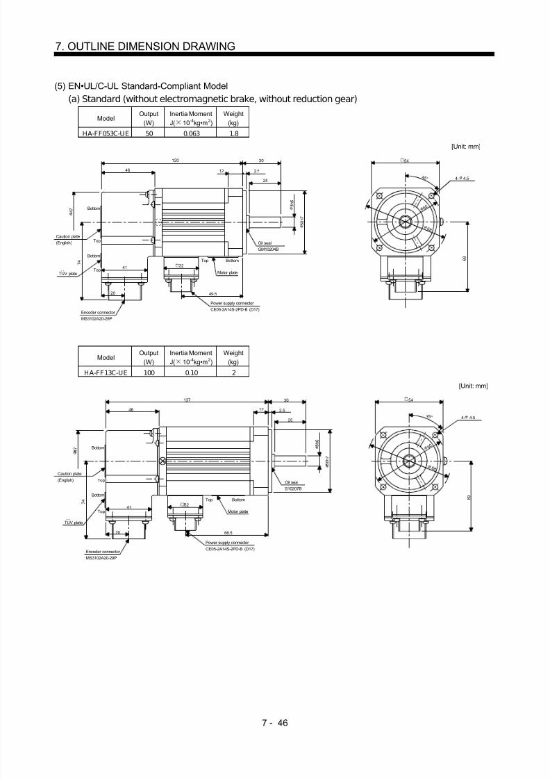
8/10/2019 Servo Motor - Instruction Manual SH(NA)-3181-D (03.00)
http://slidepdf.com/reader/full/servo-motor-instruction-manual-shna-3181-d-0300 125/368

8/10/2019 Servo Motor - Instruction Manual SH(NA)-3181-D (03.00)
http://slidepdf.com/reader/full/servo-motor-instruction-manual-shna-3181-d-0300 126/368
7 - 47
7. OUTLINE DIMENSION DRAWING
Variable DimensionsModel
Output(W) L KL
Inertia MomentJ( 10 -4kg•m 2)
Weight(kg)
HA-FF23C-UE 200 145 71.5 0.35 2.6HA-FF33C-UE 300 162 89 0.50 2.9
[Unit: mm]
46
L
Caution plate(English)
TUV plate
Encoder connector MS3102A20-29P
Bottom
Top
Bottom
Top
Motor plate
KL 2.5
4
4M4 threads, depth 15
Oil seal
S15307B
A
A
16 4
70h7
Top Bottom
4 5 °
79
Power supply connector CE05-2A14S-2PD-B (D17)
Section AA
11h6
9 0
1 0 0
4- 5.5
76
74
47
41
20
32
30
14 3
25
Variable DimensionsModel
Output(W) L KL
Inertia MomentJ( 10 -4kg•m 2)
Weight(kg)
HA-FF43C-UE 400 169 93 0.98 4.7HA-FF63C-UE 600 184 108 1.2 5.3
[Unit: mm]
Caution plate
(English)
TUV plate
44
L 40
16 3
35
25 5
A
A
Oil sealS17308B
Motor plate
Encoder connector
MS3102A20-29P Power supply connector CE05-2A14S-2PD-B (D17)
KL
BottomTop
M5 threads, depth 20Section AA
3
5
5
95h7
4 5 °
100
91
47
16h6
4- 9
1 1 51 3 5
E C
Top
Bottom
Top
Bottom
74
47
41
20 32

8/10/2019 Servo Motor - Instruction Manual SH(NA)-3181-D (03.00)
http://slidepdf.com/reader/full/servo-motor-instruction-manual-shna-3181-d-0300 127/368
7 - 48
7. OUTLINE DIMENSION DRAWING
(b) With electromagnetic brake
ModelOutput
(W)Inertia MomentJ( 10 -4kg•m 2)
Braking Force(N•m)
Weight(kg)
HA-FF053CB-UE 50 0.08 0.39 2.1
[Unit: mm]
Caution plate
TUV plate
Bottom
Top
Bottom
Top
C E
44
47
41
Encoder connector MS3102A20-29P
20
155 30
Motor plate(Opposite side)
BottomTop
12 2.5
25
Oil sealGM10204B
8h6
50h7
84
Power supply connector CE05-2A14S-2PD-B (D17)
Brake connector MS3102E10SL-4P
35.5
4 5 °
67
6 0 6 8
4- 4.5
54
3274
47
28
ModelOutput
(W)Inertia MomentJ( 10 -4kg•m 2)
Braking Force(N•m)
Weight(kg)
HA-FF13CB-UE 100 0.11 0.39 2.3
[Unit: mm]
Caution plate
TUV plate
Bottom
Top
C E
44Encoder connector
MS3102A20-29P
172
Oil sealS10207B
Power supply connector CE05-2A14S-2PD-B (D17)
Brake connector MS3102E10SL-4P
4 5 °
Motor plate
Bottom
Top
BottomTop
47
74
47
41
20101
35.5
32 28
30
12 2.5
25
8h6
50h7
67
6 0 6 8
4- 4.5
54

8/10/2019 Servo Motor - Instruction Manual SH(NA)-3181-D (03.00)
http://slidepdf.com/reader/full/servo-motor-instruction-manual-shna-3181-d-0300 128/368
7 - 49
7. OUTLINE DIMENSION DRAWING
Variable DimensionsModel
Output(W) L KL
Braking Force(N•m)
Inertia MomentJ( 10 -4kg•m 2)
Weight(kg)
HA-FF23CB-UE 200 182 109 0.48 3.5HA-FF33CB-UE 300 200 127
1.20.63 3.8
[Unit: mm]
Section AA
Caution plate(English)
TUV plate
Encoder connector MS3102A20-29P
Motor plate
Power supply connector CE05-2A14S-2PD-B (D17)
Brake connector MS3102E10SL-4P
30L
14 3
25
A
A
16 4
70h7
Oil sealS15307B
38.5
2.5
4
4M4 threads, depth 15
KL
4 5 °
79
BottomTop 32
11h6
4- 5.5
76
9 0
1 0 0
74 41
20
46
47
28
Variable DimensionsModel
Output(W) L KL
Braking Force(N•m)
Inertia MomentJ( 10 -4kg•m 2)
Weight(kg)
HA-FF43CB-UE 400 206 130 1.33 5.8
HA-FF63CB-UE 600 221 1452.3
1.55 6.4
[Unit: mm]
Section AA
Caution plate
(English)
TUV plate
C E 41
20
44 Encoder connector MS3102A20-29P
Power supply connector CE05-2A14S-2PD-B (D17)
Motor plate
Brake connector MS3102E10SL-4P
KL
42.5
Top Bottom
A
A
L
Oil sealS17308B
16h6
3
5
5
M5 threads, depth 20
4 5 °
91
28 32
100
4- 9
1 1 51 3 5
Bottom
Top
Bottom
Top
47
74
47
40
16 3
35
95h7
525

8/10/2019 Servo Motor - Instruction Manual SH(NA)-3181-D (03.00)
http://slidepdf.com/reader/full/servo-motor-instruction-manual-shna-3181-d-0300 129/368
7 - 50
7. OUTLINE DIMENSION DRAWING
7.1.3 HC-SF•HC-SFS Series
(1) Standard (without electromagnetic brake, without reduction gear)Variable dimensions
ModelOutput(kW) L KL
Inertia MomentJ( 10 -4kg•m 2)
Weight(kg)
HC-SF52HC-SF53
HC-SFS52HC-SFS53
0.5 120 51.5 6.6 5.0
HC-SF102HC-SF103
HC-SFS102HC-SFS103
1.0 145 76.5 13.7 7.0
HC-SF81 HC-SFS81 0.85HC-SF152HC-SF153
HC-SFS152HC-SFS153
1.5170 101.5 20 9.0
KL
19.5
W
V
U
A
B
CD
E
FG
H
S30457B
MS3102A20-29PCE05-2A22-23P
8 1 . 5
39.5
L 55
12 3
50
1 1 0 h 7
41
1 1 1
4 5 °
Bottom
Top
Encoder connector Power supply connector
Oil seal
Motor flange direction
Earth
Power supply connector layoutCE05-2A22-23P
[Unit: mm]
Motor plate(Opposite side)
Bottom
Top
(BC11651 BC11757 BC11768 )Z694854
1304- 9 mounting holeUse hexagon sockethead cap screw.
2 4 h 6
1 4 5
1 6 5
Variable dimensionsModel Output(kW) L H
Inertia MomentJ( 10 -4kg•m 2)
Weight(kg)
HC-SF121 HC-SFS121 1.2HC-SF202HC-SF203
HC-SFS202HC-SFS203
2.0145 68.5 42.5 12.0
HC-SF201 HC-SFS201 2.0HC-SF352HC-SF353
HC-SFS352HC-SFS353
3.5 187 110.5 82.0 19.0
W
V
U
A
B
CDE
FG
KL
19.5
8 1 . 5
39.5
L 79
18 3
75
46
1 4 2
S40608B
MS3102A20-29P
CE05-2A24-10P
Encoder connector
Power supply connector
Oil seal
Motor flange direction
Power supply connector layoutCE05-2A24-10P
Motor plate(Opposite side)
Bottom
Top
Earth
Bottom
Top
[Unit: mm]
- 0 . 0 2 5
0
0 + 0 . 0 1 0
Z695393A
4- 13.5 mounting holeUse hexagon sockethead cap screw.
176
3 5
1 1 4 . 3
(BC11769 BC11652 BC11758 )
2 0 0
2 3 0

8/10/2019 Servo Motor - Instruction Manual SH(NA)-3181-D (03.00)
http://slidepdf.com/reader/full/servo-motor-instruction-manual-shna-3181-d-0300 130/368
7 - 51
7. OUTLINE DIMENSION DRAWING
ModelOutput(kW)
Inertia MomentJ( 10 -4kg•m 2)
Weight(kg)
HC-SF301 HC-SFS301 3.0 101 23
W
V
U
AB
CDE
FG
131.5
19.5
8 1 . 5
39.5
208
18 3
75
46
1 4 2
S40608B
MS3102A20-29P
CE05-2A24-10P
Encoder connector
Power supply connector
Oil seal
Motor flange direction
Power supply connector layoutCE05-2A24-10P
Motor plate(Opposite side)
Bottom
Top
4- 13.5 mountinghole Use hexagonsocket head capscrew.
Earth
Bottom
Top
[Unit: mm]
79
4 5 °
0 + 0 . 0 1 0
- 0 . 0 2 5
0
3 5
1 1 4 . 3
176
(BC11769 )BC10628
2 0 0
2 3 0
ModelOutput(kW)
Inertia MomentJ( 10 -4kg•m 2)
Weight(kg)
HC-SF502 5.0 101 23
4 5 °
1 4 2
46
[Unit: mm]
Power supply connector layoutCE05-2A24-10P
A
B
CDE
F G
UV
WPower supply connector CE05-2A24-10P
Encoder connector MS3102A20-29P
Motor plate
(Opposite side)
208
39.5 18 3
75
79
S40608B
Oil seal
TopBottom
8 1 . 5
19.5
Top
Bottom
0 + 0 . 0 1 0
- 0 . 0 2 5
0
Earth
131.5
BC10626A
Motor flange direction
176
4- 13.5 mountinghole Use hexagonsocket head capscrew.
3 5
1 1 4 . 3
2 0 0
2 3 0

8/10/2019 Servo Motor - Instruction Manual SH(NA)-3181-D (03.00)
http://slidepdf.com/reader/full/servo-motor-instruction-manual-shna-3181-d-0300 131/368
7 - 52
7. OUTLINE DIMENSION DRAWING
ModelOutput(kW)
Inertia MomentJ( 10 -4kg•m 2)
Weight(kg)
HC-SF702 7.0 160 32
4 5 °
58
[Unit: mm]
Power supply connector layoutCE05-2A32-17P
A
BC
D
U
V
WPower supply connector CE05-2A32-17P
Encoder connector MS3102A20-29P
Motor plate
(Opposite side)
292
39.5 18 3
75
79
S40608B
Oil seal
TopBottom
8 1 . 5
19.5
Top
Bottom
0 + 0 . 0 1 0
- 0 . 0 2 5
0
Earth
210.5 Motor flange direction 1 5 0
3 5
1 1 4 . 3
4- 13.5 mountinghole Use hexagonsocket head capscrew.
176
BC10856
2 0 0
2 3 0
(2) With electromagnetic brakeVariable dimensions
ModelOutput(kW) L KL
Braking Force(N•m)
Inertia MomentJ( 10 -4kg•m 2)
Weight(kg)
HC-SF52BHC-SF53B
HC-SFS52BHC-SFS53B
0.5 153 51.5 8.5 8.3 7.5
HC-SF102BHC-SF103B
HC-SFS102BHC-SFS103B
1.0 178 76.5 8.5 15.4 9.5
HC-SF81B HC-SFS81B 0.85HC-SF152BHC-SF153B
HC-SFS152BHC-SFS153B
1.5203 101.5 8.5 21.7 11.5
KL
19.5
W
V
U
A
B
CD
E
F
G
H
8 1 . 5
L 55
12 3
50
41
1 1 1
4 5 °
MS3102A20-29P
CE05-2A22-23P
Bottom
Top
Encoder connector
Power supply connector
Motor flange direction
Earth
Power supply connector layoutCE05-2A22-23P
[Unit: mm]
Motor plate(Opposite side)
Brake
Oil sealS30457B
130
4- 9 mounting holeUse hexagon sockethead cap screw.
Z695005(BC11653 BC11762 BC11775 )
1 1 0 h 7
2 4 h 6
1 4 5
1 6 5

8/10/2019 Servo Motor - Instruction Manual SH(NA)-3181-D (03.00)
http://slidepdf.com/reader/full/servo-motor-instruction-manual-shna-3181-d-0300 132/368
7 - 53
7. OUTLINE DIMENSION DRAWING
Variable dimensionsModel
Output(kW) L KL
Braking Force(N•m)
Inertia MomentJ( 10 -4kg•m 2)
Weight(kg)
HC-SF121B HC-SFS121B 1.2HC-SF202BHC-SF203B
HC-SFS202BHC-SFS203B
2.0 193 68.5 43.1 52.5 18.0
HC-SF201B HC-SFS201B 2.0HC-SF352BHC-SF353B
HC-SFS352BHC-SFS353B
3.5235 110.5 43.1 92.0 25.0
KL
19.5
8 1 . 5
39.5
L 79
18 3
75
1 4 2 1 1 7
69
+ 0 . 0 1 0
0
4 5 °
Bottom
Top
Power supply connector CE05-2A24-10P
[Unit: mm]
Motor plate(Opposite side)
MS3102A20-29PEncoder connector
Brake connector MS3102A10SL-4P
S40608BOil seal
Bottom
Top
W
V
U
A
B
CDE
FG A B
Motor flange direction
Earth
Power supply connector layoutCE05-2A24-10P
Brake connector layoutMS3102A10SL-4P
Motor flange direction
Brake
Z695319D
4- 13.5 mounting holeUse hexagon sockethead cap screw.
176
3 5
1 1 4 . 3
- 0 . 0 2 5
0
(BC11654 BC11763 BC11776 )
2 0 02 3 0
Model Output(kW)
Braking Force(N•m)
Inertia MomentJ( 10 -4kg•m 2)
Weight(kg)
HC-SF301B HC-SFS301B 3.0 43.1 111 29.0
– 0 . 0 2 5
+ 0 . 0 1 0
Encoder connector MS3102A20-29P
Motor plate(Oposite side)
131.519.5
W
V
U
A
B
CD
E
FG
Power supplyconnector layoutCE05-2A24-10P
Motor flange drection
Oil sealS40608B 8 1 .
5
39.5
256 79
18 3
75
1 4 2
Bottom
Top
BottomTop
Brake connector MS3102A10SL-4P
1 1 7
69
Brake connectorlayoutMS3102A10SL-4P
A B
Motor flange drection
4 5 °
Brake
[Unit: mm]
46Earth
0
0
Power supplyconnector CE05-2A24-10P
3 5
1 1 4 . 3
4- 13.5 mounting holeUse hexagon sockethead cap screw.
176
BC10823(BC11776 )
2 0 0
2 3 0

8/10/2019 Servo Motor - Instruction Manual SH(NA)-3181-D (03.00)
http://slidepdf.com/reader/full/servo-motor-instruction-manual-shna-3181-d-0300 133/368
7 - 54
7. OUTLINE DIMENSION DRAWING
ModelOutput(kW)
Braking Force(N•m)
Inertia MomentJ( 10 -4kg•m 2)
Weight(kg)
HC-SF502B 5.0 43.1 111 29.0
– 0 . 0 2 5
0
+ 0 . 0 1 0
0
Encoder connector MS3102A20-29P
Motor plate(Opposite side)
131.519.5
EarthW
VU
A
BCDE
FG
Power supply connector layoutCE05-2A24-10P
Motor flange direction
Oil sealS40608B
Power supply connector
CE05-2A24-10P
8 1 . 5
39.5
256 79
18 3
75
1 4 2
Bottom
Top
BottomTop
Brake connector MS3102A10SL-4P
1 1 7
69
4 5 °
[Unit:mm]
BC10627A
46Brake connectorlayout
MS3102A10SL-4P
Brake
A B
Motor flange direction
176
4- 13.5 mounting holeUse hexagon sockethead cap screw.
3 5
1 1 4 . 3
2 0 0
2 3 0
ModelOutput(kW)
Braking Force(N•m)
Inertia MomentJ( 10 -4kg•m 2)
Weight(kg)
HC-SF702B 7.0 43.1 170 38.0
– 0 . 0 2 5
0
+ 0 . 0 1 0
0
Encoder connector MS3102A20-29P
Motor plate(Opposite side)
210.519.5
Earth
W
V
U
A
BC
DG
Power supply connectorlayoutCE05-2A32-17P
Motor flange direction
Oil sealS40608B
Power supply connector
CE05-2A32-17P
39.5
340 79
18 3
Bottom
Top
BottomTop
Brake connector MS3102A10SL-4P
69
4 5 °
[Unit:mm]
58Brake connectorlayout
MS3102A10SL-4P
Brake
A B
1 5 0
Motor flange direction
1 1 7
75
8 1 . 5 3 5
1 1 4 . 3
176
BC10857
4- 13.5 mounting holeUse hexagon sockethead cap screw.
2 0 0
2 3 0

8/10/2019 Servo Motor - Instruction Manual SH(NA)-3181-D (03.00)
http://slidepdf.com/reader/full/servo-motor-instruction-manual-shna-3181-d-0300 134/368
7 - 55
7. OUTLINE DIMENSION DRAWING
(3) With reduction gear for general industrial machine (leg type)(a) Without electromagnetic brake
Variable DimensionsModel
Output(kW)
ReductionRatio
Inertia MomentJ( 10 -4kg•m 2) L
Weight(kg)
HC-SF52G1H HC-SFS52G1H 0.5 1/35 7.5 338 28HC-SF52G1H HC-SFS52G1H 0.5 1/43 7.45 338 28HC-SF52G1H HC-SFS52G1H 0.5 1/59 7.43 338 28
HC-SF102G1H HC-SFS102G1H 1.0 1/6 16.8 363 30HC-SF102G1H HC-SFS102G1H 1.0 1/11 15.3 363 30HC-SF102G1H HC-SFS102G1H 1.0 1/17 14.9 363 30HC-SF102G1H HC-SFS102G1H 1.0 1/29 14.6 363 30HC-SF102G1H HC-SFS102G1H 1.0 1/35 14.6 363 30HC-SF152G1H HC-SFS152G1H 1.5 1/6 23.1 388 32HC-SF152G1H HC-SFS152G1H 1.5 1/11 21.5 388 32HC-SF152G1H HC-SFS152G1H 1.5 1/17 21.2 388 32
19.5
W
VU
L
55131
AF GH
BEC
D
111
81.5
68.5
A
A
155
57.5 57.5
20
82
10
8 5
230
95 95
55
1 5
1 2 0
2 5 2
MS3102A20-29P
CE05-2A22-23P
Bottom Top
Encoder connector
Power supply connector
Motor flange direction
Earth
Power supply connector layoutCE05-2A22-23P
[Unit: mm]
Motor plate
[Side view of motor only]
Section A-A
"Rotation direction"
For reverserotation command
For forwardrotation command
130
Z695267B(BC11798 )
4- 14
38h6
Variable DimensionsModel
Output(kW)
ReductionRatio
Inertia MomentJ( 10 -4kg•m 2) L
Weight(kg)
HC-SF52G1H HC-SFS52G1H 0.5 1/6 7.33 325 21HC-SF52G1H HC-SFS52G1H 0.5 1/11 6.83 325 21HC-SF52G1H HC-SFS52G1H 0.5 1/17 6.85 325 21HC-SF52G1H HC-SFS52G1H 0.5 1/29 6.78 325 21
W
VU
AFGH
BEC
D
L
111
2 1 9 2 0 7
81.5
19.5
68.5
121
110
35
A
A
45 45 60
15
135
8
7 4
1 0 0
1 2
7575
40
180MS3102A20-29P
CE05-2A22-23P
Bot tom Top
Encoder connector
Power supply connector
Motor flange direction
Earth
Power supply connector layout(CE05-2A22-23P)
[Unit: mm]
Motor plate
[Side view of motor only]
Section A-A
"Rotation direction"
For reverserotation command
For forwardrotation command 130
Z695356(BC11797 )
28h6
4- 11

8/10/2019 Servo Motor - Instruction Manual SH(NA)-3181-D (03.00)
http://slidepdf.com/reader/full/servo-motor-instruction-manual-shna-3181-d-0300 135/368
7 - 56
7. OUTLINE DIMENSION DRAWING
Variable DimensionsModel
Output(kW)
ReductionRatio
Inertia MomentJ( 10 -4kg•m 2) L
Weight(kg)
HC-SF102G1H HC-SFS102G1H 1.0 1/59 19.5 488 90HC-SF152G1H HC-SFS152G1H 1.5 1/43 25.8 513 92HC-SF152G1H HC-SFS152G1H 1.5 1/59 25.7 513 92
W
VU
AFGH
BEC
D
L
111
3 5 2
81.5
19.5
68.5
218 90
A
A
75 75 139
44
238
18
1 1 7
1 6 0
2 5
185185
75
410
MS3102A20-29P
CE05-2A22-23P
Bottom Top
Encoder connector
Power supply connector
Motor flange direction
Earth
Power supply connector layoutCE05-2A22-23P
[Unit: mm]
Motor plate
[Side view of motor only]
Section A-A
"Rotation direction"
For reverserotation command
For forwardrotation command
M10 threads, depth 18
Z695359(BC11800 )
130
60h6
4- 18
Variable DimensionsModel
Output
(kW)
Reduction
Ratio
Inertia Moment
J( 10-4
kg•m2) L
Weight
(kg)HC-SF102G1H HC-SFS102G1H 1.0 1/43 15.7 416 51HC-SF152G1H HC-SFS152G1H 1.5 1/29 22.1 441 53HC-SF152G1H HC-SFS152G1H 1.5 1/35 22.0 441 53
W
VU
AFGH
BECD
L
111
2 9 5
81.5
19.5
68.5
170 70
A
A
72.5 72.5 100
25
195
14
9 5 . 5
1 5 0
2 2
145145
65
330
MS3102A20-29P
CE05-2A22-23P
Bottom Top
Encoder connector
Power supply connector
Motor flange direction
Earth
Power supply connector layout(CE05-2A22-23P)
[Unit: mm]
Motor plate
[Side view of motor only]Section A-A
M10 threads, depth 18
"Rotation direction"
For reverserotation command
For forwardrotation command
50h6
4- 11
Z695358(BC11799 )
130

8/10/2019 Servo Motor - Instruction Manual SH(NA)-3181-D (03.00)
http://slidepdf.com/reader/full/servo-motor-instruction-manual-shna-3181-d-0300 136/368
7 - 57
7. OUTLINE DIMENSION DRAWING
ModelOutput(kW)
ReductionRatio
Inertia MomentJ( 10 -4kg•m 2)
Weight(kg)
HC-SF202G1H HC-SFS202G1H 2.0 1/6 45.6 35HC-SF202G1H HC-SFS202G1H 2.0 1/11 44.1 35HC-SF202G1H HC-SFS202G1H 2.0 1/17 43.7 35
142
381
131 55
81.5
A
A
19.5
76.5
2 6 2 5
1 2 0
1 5
55
95 95
230
8
10
UV
WCD BE
AGF
82
20
57.557.5
155MS3102A20-29P
CE05-2A24-10P
Bottom Top
Encoder connector
Power supply connector
Motor flange direction
Earth
Power supply connector layoutCE05-2A24-10P
[Unit: mm]
Motor plate
[Side view of motor only]
Section A-A
"Rotation direction"
For reverserotation command
For forwardrotation command 176
Z695802B(BC11801 )
4- 14
38h6
ModelOutput(kW)
ReductionRatio
Inertia MomentJ( 10 -4kg•m 2)
Weight(kg)
HC-SF352G1H HC-SFS352G1H 2.0 1/6 90.1 60HC-SF352G1H HC-SFS352G1H 2.0 1/11 86.2 60HC-SF352G1H HC-SFS352G1H 2.0 1/17 85.0 60
142
473
170 70
81.5
A
A
19.5
76.5
2 9 2
5 . 5
2 6 5
1 5 0
65
145 145
330
9
14
UV
WCD BE AGF
100
25
72.572.5
195
2 2
MS3102A20-29P
CE05-2A24-10P
Bottom Top
Encoder connector
Power supply connector Motor flange direction
Earth
Power supply connector layoutCE05-2A24-10P
[Unit: mm]
Motor plate
[Side view of motor only]
"Rotation direction"
For reverserotation command
For forward
rotation command
Section A-A
M10 threads, depth 18
50h6
4- 18
176
Z695803A(BC11803 )

8/10/2019 Servo Motor - Instruction Manual SH(NA)-3181-D (03.00)
http://slidepdf.com/reader/full/servo-motor-instruction-manual-shna-3181-d-0300 137/368
7 - 58
7. OUTLINE DIMENSION DRAWING
Variable DimensionsModel
Output(kW)
ReductionRatio
Inertia MomentJ( 10 -4kg•m 2) L
Weight(kg)
HC-SF202G1H HC-SFS202G1H 2.0 1/29 48.9 498 91HC-SF202G1H HC-SFS202G1H 2.0 1/35 48.6 498 91HC-SF202G1H HC-SFS202G1H 2.0 1/43 48.4 498 91
HC-SF202G1H HC-SFS202G1H 2.0 1/59 48.3 498 91HC-SF352G1H HC-SFS352G1H 3.5 1/29 88.4 540 98HC-SF352G1H HC-SFS352G1H 3.5 1/35 88.1 540 98
142
L
218 90
81.5
A
A
19. 5
76.5
3 4 1 7
1 6 0
2 5
75
185 185
410
1 118
UV
WCD BE AGF
139
44
7575
238MS3102A20-29P
CE05-2A24-10P
Bottom Top
Encoder connector
Power supply connector
Motor flange direction
Earth
Power supply connector layoutCE05-2A24-10P
[Unit: mm]
[Side view of motor only]
"Rotation direction"
For reverserotation command
For forwardrotation command
Section A-A
M10 threads, depth 18
Motor plate
Z695804A(BC11802 )
176
60h6
4- 18
3 0 0
ModelOutput(kW)
ReductionRatio
Inertia MomentJ( 10 -4kg•m 2)
Weight(kg)
HC-SF352G1H HC-SF S352G1H 3.5 1/43 106.5 139
HC-SF352G1H HC-SF S352G1H 3.5 1/59 105.9 139
142
584
262 90
81.5
A
A
19. 5
76.5
3 8 1
7 . 5
2 0 0
3 0
80
190 190
430
1 2
20
UV
WCD BE AGF
125
30
137.5137.5
335
MS3102A20-29P
CE05-2A24-10P
Bottom Top
Encoder connector
Power supply connector
Motor flange direction
Earth
Power supply connector layoutCE05-2A24-10P
[Unit: mm]
Motor plate
[Side view of motor only]
"Rotation direction"
For reverserotation command
For forwardrotation command
Section A-A
M12 threads, depth 24
70h6
4- 22
176
Z695805A(BC11804 )
3 4 0

8/10/2019 Servo Motor - Instruction Manual SH(NA)-3181-D (03.00)
http://slidepdf.com/reader/full/servo-motor-instruction-manual-shna-3181-d-0300 138/368
7 - 59
7. OUTLINE DIMENSION DRAWING
ModelOutput(kW)
ReductionRatio
Inertia MomentJ( 10 -4kg•m 2)
Weight(kg)
HC-SF502G1H 5.0 1/11 113.4 102HC-SF502G1H 5.0 1/17 109.4 102
Power supply connector layoutCE05-2A24-10P
142
561
218 90
81.5
A
A
Motor plate
19.5
76.5
3 4 1
For reverserotation command
For forwardrotation command"Rotation direction"
7
1 6 0
[Unit: mm]
2 5
75
185 185
410
1 118
Motor flange direction
UV
WCD BE
AGF
Earth
Section A-A
139
44
7575
238
M10 threads, depth 18
Encoder connector MS3102A20-29P
Power supply connector CE05-2A24-10P
39.5
1 8 1
[Side view of motor only]
Bottom Top
BC10751
176
4- 18
3 0 0
60h6
ModelOutput(kW)
ReductionRatio
Inertia MomentJ( 10 -4kg•m 2)
Weight(kg)
HC-SF502G1H 5.0 1/29 138.5 171HC-SF502G1H 5.0 1/35 138.0 171HC-SF502G1H 5.0 1/43 137.0 171
Power supply connector layoutCE05-2A24-10P
142
645
279 110
81.5
A
A
Motor plate
19.5
76.5
4 0 5
9
2 2 0
3 0
85210 210
470
1 4
Motor flange direction
22
U
V
WCD BE AGF
Earth
Section A-A
14530
160160
380
M12 threads, depth 24
Encoder connector
MS3102A20-29P
Power supply connector CE05-2A24-10P
39.5
1 7 6
For reverserotation command
For forwardrotation command"Rotation direction"
[Unit: mm]
[Side view of motor only]
Bottom Top
80h6
4- 22
176
BC10752
3 7 0
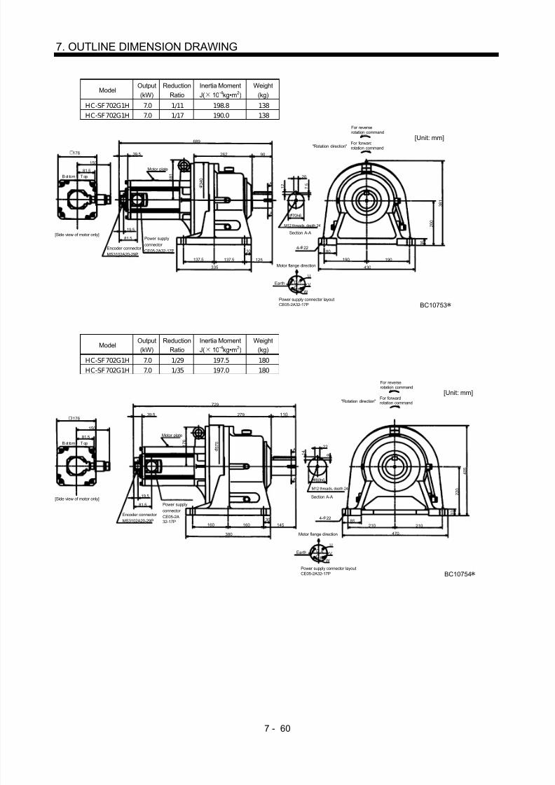
8/10/2019 Servo Motor - Instruction Manual SH(NA)-3181-D (03.00)
http://slidepdf.com/reader/full/servo-motor-instruction-manual-shna-3181-d-0300 139/368

8/10/2019 Servo Motor - Instruction Manual SH(NA)-3181-D (03.00)
http://slidepdf.com/reader/full/servo-motor-instruction-manual-shna-3181-d-0300 140/368
7 - 61
7. OUTLINE DIMENSION DRAWING
ModelOutput(kW)
ReductionRatio
Inertia MomentJ( 10 -4kg•m 2)
Weight(kg)
HC-SF702G1H 7.0 1/43 256.8 261
Power supply connector layoutCE05-2A32-17P
150
820
330 135
81.5
A
A
Motor plate
19.5
81.5
4 6 5
9
2 5 0
3 5
90
240 240
530
1 4
Motor flange direction
25
U
V
WC
D
B
AEarth
Section A-A
170
30
190190
440
M20 threads, depth 34
Encoder connector MS3102A20-29P
Power supplyconnector CE05-2A32-17P
39.5
2 1 0
For reverserotation command
For forwardrotation command"Rotation direction"
[Unit: mm]
[Side view of motor only]
Bottom Top
BC10755
176
95h6
4- 26
4 3 0

8/10/2019 Servo Motor - Instruction Manual SH(NA)-3181-D (03.00)
http://slidepdf.com/reader/full/servo-motor-instruction-manual-shna-3181-d-0300 141/368
7 - 62
7. OUTLINE DIMENSION DRAWING
(b) With electromagnetic brakeVariable Dimensions
ModelOutput(kW)
ReductionRatio
Inertia MomentJ( 10 -4kg•m 2) L
Weight(kg)
Braking Force(N•m)
HC-SF52BG1H HC-SFS52BG1H 0.5 1/35 9.2 371 33 8.5HC-SF52BG1H HC-SFS52BG1H 0.5 1/43 9.15 371 33 8.5HC-SF52BG1H HC-SFS52BG1H 0.5 1/59 9.13 371 33 8.5
HC-SF102BG1H HC-SFS102BG1H 1.0 1/6 18.5 396 35 8.5HC-SF102BG1H HC-SFS102BG1H 1.0 1/11 17.0 396 35 8.5HC-SF102BG1H HC-SFS102BG1H 1.0 1/17 16.6 396 35 8.5HC-SF102BG1H HC-SFS102BG1H 1.0 1/29 16.3 396 35 8.5HC-SF102BG1H HC-SFS102BG1H 1.0 1/35 16.3 396 35 8.5HC-SF152BG1H HC-SFS152BG1H 1.5 1/6 22.5 421 37 8.5HC-SF152BG1H HC-SFS152BG1H 1.5 1/11 23.2 421 37 8.5HC-SF152BG1H HC-SFS152BG1H 1.5 1/17 22.9 421 37 8.5
19.5
W
VU
L
55131
AF G
HBECD
111
81.5
101.5
A
A
155
57.5 57.5
20
82
10
8 5
230
95 95
55
1 5
1 2 0
2 5 2
MS3102A20-29PCE05-2A22-23P
Bottom Top
Encoder connector Power supply connector
Motor flange direction
Earth
Power supply connector layoutCE05-2A22-23P
[Unit: mm]
Motor plate
[Side view of motor only]
"Rotation direction"
For reverserotation command
For forwardrotation command
Section A-A
Brake
130
38h6
4- 14
Z695365
(BC11824 )
Variable DimensionsModel
Output(kW)
ReductionRatio
Inertia MomentJ( 10 -4kg•m 2) L
Weight(kg)
Braking Force(N•m)
HC-SF52BG1H HC-SFS52BG1H 0.5 1/6 9.03 358 23 8.5HC-SF52BG1H HC-SFS52BG1H 0.5 1/11 8.65 358 23 8.5HC-SF52BG1H HC-SFS52BG1H 0.5 1/17 8.55 358 23 8.5HC-SF52BG1H HC-SFS52BG1H 0.5 1/29 8.48 358 23 8.5
W
VU
AF GHBECD
L
111
2 1 9
2 0 7
81.5
19.5
101.5
121
110
35
A
A
45 45 60
15
135
8
7 4
1 0 0
1 2
7575
40
180MS3102A20-29P
CE05-2A22-23P
Bottom Top
Encoder connector
Power supply connector
Motor flange direction
Earth
Power supply connector layout(CE05-2A22-23P)
[Unit: mm]
Motor plate
[Side view of motor only]
"Rotation direction"
For reverserotation command
For forwardrotation command
Section A-A
Brake
(BC11823 )Z695364
28h6
4- 11
130

8/10/2019 Servo Motor - Instruction Manual SH(NA)-3181-D (03.00)
http://slidepdf.com/reader/full/servo-motor-instruction-manual-shna-3181-d-0300 142/368
7 - 63
7. OUTLINE DIMENSION DRAWING
Variable DimensionsModel
Output(kW)
ReductionRatio
Inertia MomentJ( 10 -4kg•m 2) L
Weight(kg)
Braking Force(N•m)
HC-SF102BG1H HC-SFS102BG1H 1.0 1/59 21.2 521 92 8.5HC-SF152BG1H HC-SFS152BG1H 1.5 1/43 27.5 546 94 8.5HC-SF152BG1H HC-SFS152BG1H 1.5 1/59 27.4 546 94 8.5
19.5
W
VU
L
90218
AF G
HBECD
111
81.5
101.5
A
A
238
75 75
44
139
18
1 1 7
410
185
2 5
75
1 6 0
3 5 2
185
MS3102A20-29P
CE05-2A22-23P
Bottom Top
Encoder connector
Power supply connector
Motor flange direction
Earth
Power supply connector layoutCE05-2A22-23P
[Unit: mm]
Motor plate
[Side view of motor only]
"Rotation direction"
For reverserotation command
For forwardrotation command
Brake
Section A-AM10 threads, depth 18
130
60h6
4- 18
Z695367(BC11826 )
Variable DimensionsModel
Output(kW)
ReductionRatio
Inertia MomentJ( 10 -4kg•m 2) L
Weight(kg)
Braking Force(N•m)
HC-SF102BG1H HC-SFS102BG1H 1.0 1/43 17.4 449 53 8.5HC-SF152BG1H HC-SFS152BG1H 1.5 1/29 23.8 474 55 8.5HC-SF152BG1H HC-SFS152BG1H 1.5 1/35 23.7 474 55 8.5
19.5
W
VU
L
70170
AF GHBEC
D
111
81.5
101.5
A
A
195
72.5
25
100
14
9 5 . 5
330
145
2 2
65
1 5 0
2 9 5
72.5 145
MS3102A20-29P
CE05-2A22-23P
Bottom Top
Encoder connector
Power supply connector
Motor flange direction
Earth
Power supply connector layoutCE05-2A22-23P
[Unit: mm]
Motor plate
[Side view of motor only]
"Rotation direction"
For reverserotation command
For forwardrotation command
Brake
Section A-AM10 threads, depth 18
(BC11825 )Z695366
130
50h6
4- 11

8/10/2019 Servo Motor - Instruction Manual SH(NA)-3181-D (03.00)
http://slidepdf.com/reader/full/servo-motor-instruction-manual-shna-3181-d-0300 143/368
7 - 64
7. OUTLINE DIMENSION DRAWING
ModelOutput(kW)
ReductionRatio
Inertia MomentJ( 10 -4kg•m 2)
Weight(kg)
Braking Force(N•m)
HC-SF202BG1H HC-SFS202BG1H 2.0 1/6 55.6 41 43.1HC-SF202BG1H HC-SFS202BG1H 2.0 1/11 54.1 41 43.1HC-SF202BG1H HC-SFS202BG1H 2.0 1/17 53.7 41 43.1
19.5
W
VU
429
131
AFG
BECD
142
117
69
A
A
124.5
57.5
155
10
8 5
55
1 5
20
1 2 0
2 6 2
95
81.5
A B
55
95
230
57.5 82
MS3102A20-29P
CE05-2A24-10P
Bottom Top
Encoder connector
Power supply connector
Motor flange direction
Earth
Power supply connector layoutCE05-2A24-10P
[Unit: mm]
Motor plate
[Side view of motor only]
"Rotation direction"
For reverserotation command
For forwardrotation command
Motor flange direction
Brake connector MS3102A10SL-4P
Brake connector layoutMS3102A10SL-4P
Brake
Section A-A
38h6
4- 14
176
Z695852A(BC11827 )
ModelOutput(kW)
ReductionRatio
Inertia MomentJ( 10 -4kg•m 2)
Weight(kg)
Braking Force(N•m)
HC-SF352BG1H HC-SFS352BG1H 3.5 1/6 100.1 66 43.1HC-SF352BG1H HC-SFS352BG1H 3.5 1/11 96.2 66 43.1HC-SF352BG1H HC-SFS352BG1H 3.5 1/17 95.0 66 43.1
19.5
W
VU
521
170
AFGBE
CD
142117
69
A
A
124.5
72.5
19514
9 5 . 5
65
2 2
25
1 5 0
2 6 5
145
81.5
AB
70
145
330
72.5 100
2 9 2
MS3102A20-29P
CE05-2A24-10P
Bottom Top
Encoder connector
Power supply connector
Motor flange direction
Earth
Power supply connector layoutCE05-2A24-10P
[Unit: mm]
Motor plate
[Side view of motor only]
"Rotation direction"
For reverserotation command
For forwardrotation command
Brake connector MS3102A10SL-4P
Brake connector layoutMS3102A10SL-4P
Brake
Motor flange direction
Section A-A
M10 threads, depth 18
Z695853A(BC11829 )
176
4- 18
50h6

8/10/2019 Servo Motor - Instruction Manual SH(NA)-3181-D (03.00)
http://slidepdf.com/reader/full/servo-motor-instruction-manual-shna-3181-d-0300 144/368
7 - 65
7. OUTLINE DIMENSION DRAWING
Variable DimensionsModel
Output(kW)
ReductionRatio
Inertia MomentJ( 10 -4kg•m 2) L
Weight(kg)
Braking Force(N•m)
HC-SF202BG1H HC-SFS202BG1H 2.0 1/29 58.9 546 97 43.1HC-SF202BG1H HC-SFS202BG1H 2.0 1/35 58.6 546 97 43.1HC-SF202BG1H HC-SFS202BG1H 2.0 1/43 58.4 546 97 43.1
HC-SF202BG1H HC-SFS202BG1H 2.0 1/59 58.3 546 97 43.1HC-SF352BG1H HC-SFS352BG1H 3.5 1/29 98.4 588 104 43.1HC-SF352BG1H HC-SFS352BG1H 3.5 1/35 98.1 588 104 43.1
19.5
W
VU
L
218
AFG
BECD
142
117
69 A
A
124.5
238
1 1 7
75 2 5
44
1 6 0
185
81.5
AB
410
139
18
3 4 1
90
18575 75
MS3102A20-29P
CE05-2A24-10P
Bottom TopEncoder connector
Power supply connector
Motor flange direction
Earth
Power supply connector layoutCE05-2A24-10P
[Unit: mm]
Motor plate
[Side view of motor only]
"Rotation direction"
For reverserotation command
For forwardrotation command
Brake connector MS3102A10SL-4P
Brake connector layoutMS3102A10SL-4P
Brake
Motor flange direction
Section A-AM10 threads, depth 18
4- 18
60h6
176
Z695854A(BC11828 )
3 0 0
ModelOutput(kW)
ReductionRatio
Inertia MomentJ( 10 -4kg•m 2)
Weight(kg)
Braking Force(N•m)
HC-SF352BG1H HC-SFS352BG1H 3.5 1/43 116.5 145 43.1
HC-SF352BG1H HC-SFS352BG1H 3.5 1/59 115.9 145 43.1
19.5
W
VU
632
262
AF GBE
CD
142
117
69 A
A
124.5
335
1 2 7 . 5
80
3 0
30
2 0 0
190
81.5
AB 430125
20
3 8 1
90
190137.5 137.5
Section A-AM12 threads, depth 24
MS3102A20-29P
CE05-2A24-10P
Bottom Top
Encoder connector
Power supply connector
Motor flange direction
Earth
Power supply connector layoutCE05-2A24-10P
[Unit: mm]
Motor plate
[Side view of motor only]
"Rotation direction"
For reverserotation command
For forwardrotation commandBrake connector
MS3102A10SL-4P
Brake connector layoutMS3102A10SL-4P
Brake
Motor flange direction
Z695855A(BC11830 )
176
4- 22
70h6

8/10/2019 Servo Motor - Instruction Manual SH(NA)-3181-D (03.00)
http://slidepdf.com/reader/full/servo-motor-instruction-manual-shna-3181-d-0300 145/368
7 - 66
7. OUTLINE DIMENSION DRAWING
ModelOutput(kW)
ReductionRatio
Inertia MomentJ( 10 -4kg•m 2)
Weight(kg)
HC-SF502BG1H 5.0 1/11 123.4 108HC-SF502BG1H 5.0 1/17 119.4 108
Power supply connector layoutCE05-2A24-10P
142
609
218 90117
A
A
Motor plate
19.5
69
3 4 1
7
1 6 0
2 5
75
185 185
410
1 1
Motor flange direction
18
UV
WCD BE AGF
Earth
Section A-A
139
44
7575
238
M10 threads, depth 18
Encoder connector MS3102A20-29P
Power supply connector
CE05-2A24-10P
39.5
1 8 181.5
Brake connector layoutMS3102A10SL-4P
Motor flange direction
B ABrake
124.5
Brake connector MS3102A10SL-4P
Bottom Top
[Side view of motor only]
[Unit: mm]
"Rotation direction"
For reverserotation command
For forwardrotation command
4- 18
60h6
176
BC11028
3 0 0
ModelOutput(kW)
ReductionRatio
Inertia MomentJ( 10 -4kg•m 2)
Weight(kg)
HC-SF502BG1H 5.0 1/29 148.5 177HC-SF502BG1H 5.0 1/35 148.0 177HC-SF502BG1H 5.0 1/43 147.0 177
142
693
279 110
117
A
A
Motor plate
19.5
69
4 0 5
9
2 2 0
3 0
85210 210
470
1 422
Power supply connector layoutCE05-2A24-10P
Motor flange direction
U
V
WCD BE
AGF
Earth
Section A-A
14530
160160
380
M12 threads, depth 24
Encoder connector MS3102A20-29P
Power supplyconnector CE05-2A24-10P
39.5
1 7 681.5
Brake connector layoutMS3102A10SL-4P
Motor flange direction
B ABrake
124.5
Brake connector MS3102A10SL-4P
Bottom Top
[Unit: mm]
"Rotation direction"
For reverserotation command
For forward
rotation command
[Side view of motor only]
3 7 0
80h6
BC11029
176
4- 22

8/10/2019 Servo Motor - Instruction Manual SH(NA)-3181-D (03.00)
http://slidepdf.com/reader/full/servo-motor-instruction-manual-shna-3181-d-0300 146/368
7 - 67
7. OUTLINE DIMENSION DRAWING
ModelOutput(kW)
ReductionRatio
Inertia MomentJ( 10 -4kg•m 2)
Weight(kg)
HC-SF702BG1H 7.0 1/11 208.8 144HC-SF702BG1H 7.0 1/17 200.0 144
Power supply connector layoutCE05-2A32-17P
150
737
262 90
117
A
A
Motor plate
19.5
69
3 8 1
7 . 5
2 0 0
3 0
80
190 190
430
1 2
Motor flange direction
20
U
V
WCD
B
AEarth
Section A-A
125
30
137.5137.5
335
M12 threads, depth 24
Encoder connector MS3102A20-29P
Power supplyconnector CE05-2A32-17P
1 8 181.5
Brake connector layoutMS3102A10SL-4P
Motor flange direction
B ABrake
129.5
Brake connector MS3102A10SL-4P
Bottom Top
[Unit: mm]
"Rotation direction"
For reverserotation command
For forwardrotation command
[Side view of motor only]
176
BC11030
70h6
3 4 0
4- 22
ModelOutput(kW)
ReductionRatio
Inertia MomentJ( 10 -4kg•m 2)
Weight(kg)
HC-SF702BG1H 7.0 1/29 207.5 186HC-SF702BG1H 7.0 1/35 207.0 186
Power supply connector layoutCE05-2A32-17P
150
777
279 110
117
A
A
Motor plate
19.5
69
4 0 5
9
2 2 0
3 0
85210 210
470
1 4
Motor flange direction
22
U
V
WCD
B
AEarth
Section A-A
14530
160160
380
M12 threads, depth 24
Encoder connector MS3102A20-29P
Power supplyconnector CE05-2A32-17P
1 7 681.5
Brake connector layoutMS3102A10SL-4P
Motor flange direction
B ABrake
129.5
Brake connector
MS3102A10SL-4P
B ot tom Top
[Unit: mm]
"Rotation direction"
For reverserotation command
For forwardrotation command
[Side view of motor only]
3 7 0
80h6
4- 22
BC11031
176

8/10/2019 Servo Motor - Instruction Manual SH(NA)-3181-D (03.00)
http://slidepdf.com/reader/full/servo-motor-instruction-manual-shna-3181-d-0300 147/368
7 - 68
7. OUTLINE DIMENSION DRAWING
ModelOutput(kW)
ReductionRatio
Inertia MomentJ( 10 -4kg•m 2)
Weight(kg)
HC-SF702BG1H 7.0 1/43 266.8 267
150
868
330 135
117
A
A
Motor plate
19.5
69
4 6 5
9
2 5 0
3 5
90240 240
530
1 425
Power supply connector layoutCE05-2A32-17P
Motor flange direction
U
V
WCD
B
AEarth
Section A-A
170
30
190190
440
M20 threads, depth 34
Encoder connector MS3102A20-29P
Power supplyconnector CE05-2A32-17P
2 1 081.5
Brake connector layoutMS3102A10SL-4P
Motor flange direction
B ABrake
129.5
Brake connector MS3102A10SL-4P
Bottom Top
[Unit: mm]
"Rotation direction"
For reverserotation command
For forward
rotation command
[Side view of motor only]
176
BC11032
95h6
4- 26
4 3 0

8/10/2019 Servo Motor - Instruction Manual SH(NA)-3181-D (03.00)
http://slidepdf.com/reader/full/servo-motor-instruction-manual-shna-3181-d-0300 148/368
7 - 69
7. OUTLINE DIMENSION DRAWING
(4) With reduction gear for general industrial machine (flange type)(a) Without electromagnetic brake
Variable DimensionsModel
Output(kW)
ReductionRatio
Inertia MomentJ( 10 -4kg•m 2) L
Weight(kg)
HC-SF52G1 HC-SFS52G1 0.5 1/35 7.5 269 27HC-SF52G1 HC-SFS52G1 0.5 1/43 7.45 269 27HC-SF52G1 HC-SFS52G1 0.5 1/59 7.43 269 27
HC-SF102G1 HC-SFS102G1 1.0 1/6 16.8 294 29HC-SF102G1 HC-SFS102G1 1.0 1/11 15.3 294 29HC-SF102G1 HC-SFS102G1 1.0 1/17 14.9 294 29HC-SF102G1 HC-SFS102G1 1.0 1/29 14.6 294 29HC-SF102G1 HC-SFS102G1 1.0 1/35 14.6 294 29HC-SF152G1 HC-SFS152G1 1.5 1/6 23.1 319 31HC-SF152G1 HC-SFS152G1 1.5 1/11 21.5 319 31HC-SF152G1 HC-SFS152G1 1.5 1/17 21.2 319 31
19.5
W
VU
L 69117
AF GH
BECD
111
81.5
68.5
A
A 10
8 5
1 3 2
13 4
55
3 0 °
MS3102A20-29P CE05-2A22-23P
Bottom Top
Encoder connector Power supply connector Motor flange direction
Earth
Power supply connector layoutCE05-2A22-23P
[Unit: mm]
Motor plate
[Side view of motor only]
"Rotation direction"
For reverserotation command
For forwardrotation command
Section A-A
1 4 0 f 8
2 1 0
38h6
6- 11
1 8 0
Z695270C(BC11811 )
130
Variable DimensionsModel
Output(kW)
ReductionRatio
Inertia MomentJ( 10 -4kg•m 2) L
Weight(kg)
HC-SF52G1 HC-SFS52G1 0.5 1/6 7.33 277 18.5HC-SF52G1 HC-SFS52G1 0.5 1/11 6.98 277 18.5HC-SF52G1 HC-SFS52G1 0.5 1/17 6.85 277 18.5HC-SF52G1 HC-SFS52G1 0.5 1/29 6.78 277 18.5
W
VU
AFGH
BECD
L
111
1 1 9
1 0 7
81.5
19.5
68.5
108 35
48
A
A
8
4
62
9 3
7
4 5 °
MS3102A20-29P
CE05-2A22-23P
Bottom Top
Encoder connector
Power supply connector
Motor flange direction
Earth
Power supply connector layout(CE05-2A22-23P)
[Unit: mm]
Motor plate
[Side view of motor only]
"Rotation direction"
For reverserotation command
For forwardrotation command
Section A-A
Z695360(BC11810 )
130
28h6
4- 11
1 3 4
1 1 0 f 8
1 6 0 1 5 0

8/10/2019 Servo Motor - Instruction Manual SH(NA)-3181-D (03.00)
http://slidepdf.com/reader/full/servo-motor-instruction-manual-shna-3181-d-0300 149/368
7 - 70
7. OUTLINE DIMENSION DRAWING
Variable DimensionsModel
Output(kW)
ReductionRatio
Inertia MomentJ( 10 -4kg•m 2) L
Weight(kg)
HC-SF102G1 HC-SFS102G1 1.0 1/59 19.5 399 83HC-SF152G1 HC-SFS152G1 1.5 1/43 25.8 424 85HC-SF152G1 HC-SFS152G1 1.5 1/59 25.7 424 85
W
VU
AFGH
BECD
L
111
1 9 281.5
19.568.5
219
89
A
A
18
1 1
20 4
7
228
6 0 °
MS3102A20-29P
CE05-2A22-23P
Bottom Top
Encoder connector
Power supply connector
Motor flange direction
Earth
Power supply connector layoutCE05-2A22-23P
[Unit: mm]
Motor plate
[Side view of motor only]
"Rotation direction"
For reverserotation command
For forwardrotation command
Section A-A
M10 threads, depth 18
(BC11813 )
130
2 7 0 f 8
3 4 0
60h6
3 0 0
6- 11
3 1 0
Z695363
Variable DimensionsModel
Output(kW)
ReductionRatio
Inertia MomentJ( 10 -4kg•m 2) L
Weight(kg)
HG-SF102G1 HG-SFS102G1 1.0 1/43 15.7 340 48HC-SF152G1 HC-SFS152G1 1.5 1/29 22.1 365 50
HC-SF152G1 HC-SFS152G1 1.5 1/35 22.0 365 50
W
VU
AFGH
BECD
L
111
1 4 5
81.5
19.5
68.5
164
76
A
A
14
9
15 4
70
5 . 5
1836 0 °
MS3102A20-29P
CE05-2A22-23P
Bottom Top
Encoder connector
Power supply connector
Motor flange direction
Earth
Power supply connector layout(CE05-2A22-23P)
[Unit: mm]
Motor plate
[Side view of motor only]
"Rotation direction"
For reverserotation command
For forwardrotation command
Section A-A
M10 threads, depth 18
130
2 3 0
2 0 0 f 8
2 6 0
50h6
2 3 0
6- 11
Z695362(BC11812 )

8/10/2019 Servo Motor - Instruction Manual SH(NA)-3181-D (03.00)
http://slidepdf.com/reader/full/servo-motor-instruction-manual-shna-3181-d-0300 150/368
7 - 71
7. OUTLINE DIMENSION DRAWING
ModelOutput(kW)
ReductionRatio
Inertia MomentJ( 10 -4kg•m 2)
Weight(kg)
HC-SF202G1 HC-SFS202G1 2.0 1/6 45.6 34HC-SF202G1 HC-SFS202G1 2.0 1/11 44.1 34HC-SF202G1 HC-SFS202G1 2.0 1/17 43.7 34
142
312 69
55
81.5
A
A
76.5
1 4 2
5
3 0 °
8
10
UV
WCD BE AGF
117
413
19.5
MS3102A20-29P
CE05-2A24-10P
Bottom Top
Encoder connector
Power supply connector
Motor flange direction
Earth
Power supply connector layoutCE05-2A24-10P
[Unit: mm]
Motor plate
[Side view of motor only]
"Rotation direction"
For reverserotation command
For forwardrotation command
Section A-A
6- 11
1 8 0
38h6
1 4 0 f 8
2 1 0
2 0 4
176
(BC11814 )Z695806A
ModelOutput(kW)
ReductionRatio
Inertia MomentJ( 10 -4kg•m 2)
Weight(kg)
HC-SF352G1 HC-SFS352G1 3.5 1/6 90.1 57HC-SF352G1 HC-SFS352G1 3.5 1/11 86.2 57HC-SF352G1 HC-SFS352G1 3.5 1/17 85.0 57
142
397 76
70
81.5
A
A
76.5
1 4 2
5 . 5
6 0 °
9
209
UV
WCD BE AGF
164
415
19.5
14
MS3102A20-29P CE05-2A24-10P
Bottom Top
Encoder connector Power supply connector Motor flange direction
Earth
Power supply connector layoutCE05-2A24-10P
[Unit: mm]
Motor plate
[Side view of motor only]
"Rotation direction"
For reverserotation command
For forwardrotation command
Section A-AM10 threads, depth 18
176
2 3 0
2 0 0 f 8
2 6 0
50h6
6- 11
2 3 0
(BC11816 )Z695807A

8/10/2019 Servo Motor - Instruction Manual SH(NA)-3181-D (03.00)
http://slidepdf.com/reader/full/servo-motor-instruction-manual-shna-3181-d-0300 151/368
7 - 72
7. OUTLINE DIMENSION DRAWING
Variable DimensionsModel
Output(kW)
ReductionRatio
Inertia MomentJ( 10 -4kg•m 2) L
Weight(kg)
HC-SF202G1 HC-SFS202G1 2.0 1/29 48.9 409 84HC-SF202G1 HC-SFS202G1 2.0 1/35 48.6 409 84HC-SF202G1 HC-SFS202G1 2.0 1/43 48.4 409 84
HC-SF202G1 HC-SFS202G1 2.0 1/59 48.3 409 84HC-SF352G1 HC-SFS352G1 3.5 1/29 88.4 451 91HC-SF352G1 HC-SFS352G1 3.5 1/35 88.1 451 91
142
L 89
4
81.5
A
A
76.5
1 8 1
7
6 0 °
1 118
UV
WCD BE AGF
219
4
20
19. 5
2 2 8
1 5 °
Section A-A
M10 threads, depth 18
MS3102A20-29P CE05-2A24-10P
Bottom Top
Encoder connector Power supply connector
Motor flange direction
Earth
Power supply connector layoutCE05-2A24-10P
[Unit: mm]
Motor plate
[Side view of motor only]
"Rotation direction"
For reverserotation command
For forwardrotation command
3 1 0
6- 11
60h6
2 7 0 f 8
3 4 0
3 0 0
176
Z695808A(BC11815 )
ModelOutput(kW)
ReductionRatio
Inertia MomentJ( 10 -4kg•m 2)
Weight(kg)
HC-SF352G1 HC-SFS352G1 3.5 1/43 106.5 84
HC-SF352G1 HC-SFS352G1 3.5 1/59 105.9 84
142
94
81.5
A
A
76.5
1 2
2 2 .5 °
7 . 5
20
UV
WCD BE AGF
70h6
490
522
19. 5
243258
MS3102A20-29P CE05-2A24-10P
Bot tom Top
Encoder connector Power supply connector
Motor flange direction
Earth
Power supply connector layoutCE05-2A24-10P
[Unit: mm]
Motor plate
Side view of motor only]
"Rotation direction"
For reverserotation command
For forwardrotation command
1-M12 threads, depth 24
Section A-A
176
8- 14
3 6 0
3 1 6 f 8
4 0 0
3 4 0
Z695809A(BC11817 )

8/10/2019 Servo Motor - Instruction Manual SH(NA)-3181-D (03.00)
http://slidepdf.com/reader/full/servo-motor-instruction-manual-shna-3181-d-0300 152/368
7 - 73
7. OUTLINE DIMENSION DRAWING
ModelOutput(kW)
ReductionRatio
Inertia MomentJ( 10 -4kg•m 2)
Weight(kg)
HC-SF502G1 5.0 1/11 113.4 95HC-SF502G1 5.0 1/17 109.4 95
Power supply connector layoutCE05-2A24-10P
142
472
219
89
A
A
Motor plate
19.5
1 8 1
7
6 0 °
1 1
Motor flange direction
18
UV
WCD BE
AGF
Earth
Section A-A
M10 threads, depth 18
Encoder connector MS3102A20-29P
Power supply connector CE05-2A24-10P
39.5
1 8 181.5
76.5
20 4
85
2 2 8
1 5 °
Bottom Top
[Side view of motor only]
[Unit: mm]
"Rotation direction"
For reverserotation command
For forwardrotation command
3 0 0 2 7 0 f 8
3 4 0
60h6
6- 11
3 1 0
BC10756
176
ModelOutput(kW)
ReductionRatio
Inertia MomentJ( 10 -4kg•m 2)
Weight(kg)
HC-SF502G1 5.0 1/29 138.5 162HC-SF502G1 5.0 1/35 138.0 162HC-SF502G1 5.0 1/43 137.0 162
Power supply connector layoutCE05-2A24-10P
142
535
279
110
A
A
Motor plate
19.5
9
2 2 .5 °
1 4
Motor flange direction
22
UV
WCD BE
AGF
Earth
Section A-A
1-M12 threads, depth 24
Encoder connector MS3102A20-29P
Power supply connector CE05-2A24-10P
39.5
1 7 681.5
76.5
22 5
105
258
Bottom Top
[Side view of motor only]
[Unit: mm]
"Rotation direction"
For reverserotation command
For forwardrotation command
176
3 7 0 3 4 5 f 8
4 3 0
80h6
8- 18
3 9 0
BC10757

8/10/2019 Servo Motor - Instruction Manual SH(NA)-3181-D (03.00)
http://slidepdf.com/reader/full/servo-motor-instruction-manual-shna-3181-d-0300 153/368
7 - 74
7. OUTLINE DIMENSION DRAWING
ModelOutput(kW)
ReductionRatio
Inertia MomentJ( 10 -4kg•m 2)
Weight(kg)
HC-SF702G1 7.0 1/11 198.8 146HC-SF702G1 7.0 1/17 190.0 146
Power supply connector layoutCE05-2A32-17P
150
595
258
94
A
A
Motor plate
19.5
7 . 5
2 2 .5 °
1 2
Motor flange direction
20
U
V
WCD
B AEarth
Section A-A1-M12 threads, depth 24
Encoder connector
MS3102A20-29P
Power supply connector CE05-2A32-17P
39.5
1 8 181.5
81.5
22 5
89
243
B ot to m Top
[Side view of motor only]
[Unit: mm]
"Rotation direction"
For reverserotation command
For forwardrotation command
BC10758
176
70h6
8- 14
3 6 0
3 4 0 3 1 6 f 8
4 0 0
ModelOutput(kW)
ReductionRatio
Inertia MomentJ( 10 -4kg•m 2)
Weight(kg)
HC-SF702G1 7.0 1/29 197.5 171HC-SF702G1 7.0 1/35 197.0 171
150
619
279
110
A
A
Motor plate
19.5
9
2 2 .5 °
1 4
22
Power supply connector layoutCE05-2A32-17P
Motor flange direction
U
V
WCD
B
AEarth
Section A-A
1-M12 threads, depth 24Encoder connector MS3102A20-29P
Power supplyconnector CE05-2A32-17P
39.5
1 7 681.5
81.5
22 5
105
258
Bottom Top
[Side view of motor only]
[Unit: mm]
"Rotation direction"
For reverserotation command
For forwardrotation command
3 7 0 3 4 5 f 8
4 3 0
80h6
8- 18
BC10759
176
3 9 0

8/10/2019 Servo Motor - Instruction Manual SH(NA)-3181-D (03.00)
http://slidepdf.com/reader/full/servo-motor-instruction-manual-shna-3181-d-0300 154/368
7 - 75
7. OUTLINE DIMENSION DRAWING
ModelOutput(kW)
ReductionRatio
Inertia MomentJ( 10 -4kg•m 2)
Weight(kg)
HC-SF702G1 7.0 1/43 256.8 240
150
675
320
145
A
A
Motor plate
19.5
9 1 425
Power supply connector layoutCE05-2A32-17P
Motor flange direction
U
V
WCD
B
AEarth
Section A-A
1-M20 threads, depth 34
Encoder connector MS3102A20-29P
Power supplyconnector CE05-2A32-17P
39.5
2 1 081.5
81.5
30 6
135
285 1 5 °
Bottom Top
[Side view of motor only]
[Unit: mm]
"Rotation direction"
For reverserotation command
For forward
rotation command
BC10760
176
95h6
12- 18
4 5
0
4 0 0 f 8
4 9 0
4 3 0

8/10/2019 Servo Motor - Instruction Manual SH(NA)-3181-D (03.00)
http://slidepdf.com/reader/full/servo-motor-instruction-manual-shna-3181-d-0300 155/368
7 - 76
7. OUTLINE DIMENSION DRAWING
(b) With electromagnetic brakeVariable Dimensions
ModelOutput(kW)
Reduction RatioInertia MomentJ( 10 -4kg•m 2) L
Weight(kg)
Braking Force(N•m)
HC-SF52BG1 HC-SFS52BG1 0.5 1/35 9.2 302 32.5 8.5HC-SF52BG1 HC-SFS52BG1 0.5 1/43 9.15 302 32.5 8.5HC-SF52BG1 HC-SFS52BG1 0.5 1/59 9.13 302 32.5 8.5
HC-SF102BG1 HC-SFS102BG1 1.0 1/6 18.5 327 34.5 8.5HC-SF102BG1 HC-SFS102BG1 1.0 1/11 17.0 327 34.5 8.5HC-SF102BG1 HC-SFS102BG1 1.0 1/17 16.6 327 34.5 8.5HC-SF102BG1 HC-SFS102BG1 1.0 1/29 16.3 327 34.5 8.5HC-SF102BG1 HC-SFS102BG1 1.0 1/35 16.3 327 34.5 8.5HC-SF152BG1 HC-SFS152BG1 1.5 1/6 22.5 352 36.5 8.5HC-SF152BG1 HC-SFS152BG1 1.5 1/11 23.2 352 36.5 8.5HC-SF152BG1 HC-SFS152BG1 1.5 1/17 22.9 352 36.5 8.5
W
VU
AF GHBEC
D
L
111
81.5
19.5
101.5
117
69
A
A
10
8
13 4
1 3 2 55
3 0 °
5
MS3102A20-29PCE05-2A22-23P
Bottom Top
Encoder connector Power supply connector
Motor flange direction
Earth
Power supply connector layout(CE05-2A22-23P)
[Unit: mm]
Motor plate
[Side view of motor only]
"Rotation direction"
For reverserotation command
For forwardrotation command
Brake
Section A-A
2 0 4
1 4 0 f 8
2 1 0
38h6
6- 11
1 8 0
(BC11837 )
130
Z695369
Variable DimensionsModel
Output(kW)
Reduction RatioInertia MomentJ( 10 -4kg•m 2) L
Weight(kg)
Braking Force(N•m)
HC-SF52BG1 HC-SFS52BG1 0.5 1/6 9.03 310 20.5 8.5HC-SF52BG1 HC-SFS52BG1 0.5 1/11 8.65 310 20.5 8.5HC-SF52BG1 HC-SFS52BG1 0.5 1/17 8.55 310 20.5 8.5HC-SF52BG1 HC-SFS52BG1 0.5 1/29 8.48 310 20.5 8.5
W
VU
AFG
HBEC
D
L
111
81.5
19.5
101.5
108
48
A
A
8
7
62
3
1 1 9
4 5 °
4
35
9
1 0 7
Section A-A
MS3102A20-29P
CE05-2A22-23P
Bottom Top
Encoder connector
Power supply connector
Motor flange direction
Earth
Power supply connector layout(CE05-2A22-23P)
[Unit: mm]
Motor plate
[Side view of motor only]
"Rotation direction"
For reverserotation command
For forwardrotation command
Brake
130
28h6
4- 11
(BC11836 )
1 3 4
1 1 0 f 8
1 6 0 1 5 0
Z695368

8/10/2019 Servo Motor - Instruction Manual SH(NA)-3181-D (03.00)
http://slidepdf.com/reader/full/servo-motor-instruction-manual-shna-3181-d-0300 156/368
7 - 77
7. OUTLINE DIMENSION DRAWING
Variable DimensionsModel
Output(kW)
ReductionRatio
Inertia MomentJ( 10 -4kg•m 2) L
Weight(kg)
Braking Force(N•m)
HC-SF102BG1 HC-SFS102BG1 1.0 1/59 21.2 432 85 8.5HC-SF152BG1 HC-SFS152BG1 1.5 1/43 27.5 457 87 8.5HC-SF152BG1 HC-SFS152BG1 1.5 1/59 27.4 457 87 8.5
(BC11839 )
W
VU
AF GHBECD
L
111
1 9 281.5
19.5
101.5
219
89
A
A
18
1 1 7
420 228
3 4 0
6 0 °
MS3102A20-29P
CE05-2A22-23P
Bottom Top
Encoder connector
Power supply connector Motor flange direction
Earth
Power supply connector layout(CE05-2A22-23P)
[Unit: mm]
Motor plate
[Side view of motor only]
"Rotation direction"
For reverserotation command
For forwardrotation command
Brake
Section A-A
M10 threads, depth 18
3 0 0
2 7 0 f 8
60h6
6- 11
3 1 0
130
Z695371
Variable DimensionsModel
Output(kW)
ReductionRatio
Inertia MomentJ( 10 -4kg•m 2) L
Weight(kg)
Braking Force(N•m)
HC-SF102BG1 HC-SFS102BG1 1.0 1/43 17.4 373 50 8.5HC-SF152BG1 HC-SFS152BG1 1.5 1/29 23.8 398 52 8.5
HC-SF152BG1 HC-SFS152BG1 1.5 1/3 23.7 398 52 8.5
W
VU
AF GHBEC
D
L
111
1 4 5
81.5
19.5
101.5
164
76
A
A
14
9 5 . 5
415183
6 0 °
70
MS3102A20-29P
CE05-2A22-23P
Bottom Top
Encoder connector
Power supply connector
Motor flange direction
Earth
Power supply connector layout(CE05-2A22-23P)
[Unit: mm]
Motor plate
[Side view of motor only]
"Rotation direction"
For reverserotation command
For forwardrotation command
Brake
Section A-AM10 threads, depth 18
(BC117838 )
130
50h6
6- 11
2 3 0
2 0 0 f 8
2 6 0
2 3 0
Z695370

8/10/2019 Servo Motor - Instruction Manual SH(NA)-3181-D (03.00)
http://slidepdf.com/reader/full/servo-motor-instruction-manual-shna-3181-d-0300 157/368
7 - 78
7. OUTLINE DIMENSION DRAWING
ModelOutput(kW)
ReductionRatio
Inertia MomentJ( 10 -4kg•m 2)
Weight(kg)
Braking Force(N•m)
HC-SF202BG1 HC-SFS202BG1 2.0 1/6 55.6 40 43.1HC-SF202BG1 HC-SFS202BG1 2.0 1/11 54.1 40 43.1HC-SF202BG1 HC-SFS202BG1 2.0 1/17 53.7 40 43.1
142
360 69
5581.5
A
A
69
1 4 2
5
3 0 °
8
10
UV
WCD BE AGF
117
1 4 0 f 8
413
19.5
124.5
117
A B
MS3102A20-29P
CE05-2A24-10P
Bottom Top
Encoder connector
Power supply connector
Motor flange direction
Earth
Power supply connector layoutCE05-2A24-10P
[Unit: mm]
Motor plate
[Side view of motor only]
"Rotation direction"
For reverserotation command
For forwardrotation command
Motor flange direction
Brake connector MS3102A10SL-4P
Brake connector layoutMS3102A10SL-4P
Brake
Section A-A
2 0 4
2 1 0
38h6
6- 11
1 8 0
176
Z695856A (BC11840 )
ModelOutput(kW)
ReductionRatio
Inertia MomentJ( 10 -4kg•m 2)
Weight(kg)
Braking Force(N•m)
HC-SF352BG1 HC-SFS352BG1 3.5 1/6 100.1 63 43.1HC-SF352BG1 HC-SFS352BG1 3.5 1/11 96.2 63 43.1HC-SF352BG1 HC-SFS352BG1 3.5 1/17 95.0 63 43.1
142
445 76
70
81.5
A
A
69
1 4 2
5 . 5
9
14
U V
WCD BE AGF
164
2 0 0 f 8
415
19.5
124.5
117
A B
209
MS3102A20-29P
CE05-2A24-10P
Bottom Top
Encoder connector
Power supply connector
Motor flange direction
Earth
Power supply connector layoutCE05-2A24-10P
[Unit: mm]
Motor plate
[Side view of motor only]
"Rotation direction"
For reverserotation command
For forwardrotation command
Motor flange direction
Brake connector MS3102A10SL-4P
Brake connector layoutMS3102A10SL-4P
Brake
Section A-A
M10 threads, depth 18
Z695857A(BC11842 )
2 6 0
2 3 0
50h6
6- 11
2 3 0
6 0
176

8/10/2019 Servo Motor - Instruction Manual SH(NA)-3181-D (03.00)
http://slidepdf.com/reader/full/servo-motor-instruction-manual-shna-3181-d-0300 158/368
7 - 79
7. OUTLINE DIMENSION DRAWING
Variable DimensionsModel
Output(kW)
ReductionRatio
Inertia MomentJ( 10 -4kg•m 2) L
Weight(kg)
Braking Force(N•m)
HC-SF202BG1 HC-SFS202BG1 2.0 1/29 58.9 457 90 43.1HC-SF202BG1 HC-SFS202BG1 2.0 1/35 58.6 457 90 43.1HC-SF202BG1 HC-SFS202BG1 2.0 1/43 58.4 457 90 43.1
HC-SF202BG1 HC-SFS202BG1 2.0 1/59 58.3 457 90 43.1HC-SF352BG1 HC-SFS352BG1 3.5 1/29 98.4 499 97 43.1HC-SF352BG1 HC-SFS352BG1 3.5 1/35 98.1 499 97 43.1
142
L 89
4
81.5
A
A
69
1 8 1
7
6 0 °
1 118
UV
WCD BE AGF
219
4
20
19. 5
2 2 8
1 5 °
124.5
117
AB
MS3102A20-29P
CE05-2A24-10P
Bottom Top
Encoder connector
Power supply connector
Motor flange direction
Earth
Power supply connector layoutCE05-2A24-10P
[Unit: mm]
Motor plate
[Side view of motor only]
"Rotation direction"
For reverserotation command
For forwardrotation command
Motor flange direction
Brake connector MS3102A10SL-4P
Brake connector layoutMS3102A10SL-4P
Brake
Section A-A
M10 threads, depth 18
3 0 0 2 7 0 f 8
3 4 0
60h6
6- 11
3 1 0
176
Z695858A(BC11841 )
ModelOutput(kW)
ReductionRatio
Inertia MomentJ( 10 -4kg•m 2)
Weight(kg)
Braking Force(N•m)
HC-SF352BG1 HC-SFS352BG1 3.5 1/43 116.5 139 43.1HC-SF352BG1 HC-SFS352BG1 3.5 1/59 115.9 139 43.1
142
538 94
5
81.5
A
A
69
7 . 5
2 2 .5 °
70h6
1 2
20
UV
WCD BE AGF
258
22
19.5
124.5
117
AB
243
Section A-A
1-M12 threads, depth 24
MS3102A20-29P
CE05-2A24-10P
Bottom Top
Encoder connector
Power supply connector
Motor flange direction
Earth
Power supply connector layoutCE05-2A24-10P
[Unit: mm]
Motor plate
[Side view of motor only]
"Rotation direction"
For reverserotation command
For forwardrotation command
Motor flange direction
Brake connector MS3102A10SL-4P
Brake connector layoutMS3102A10SL-4P
Brake
Z695859A(BC11843 )
8- 14
3 6
0
3 1 6 f 8
4 0 0
3 4 0
176

8/10/2019 Servo Motor - Instruction Manual SH(NA)-3181-D (03.00)
http://slidepdf.com/reader/full/servo-motor-instruction-manual-shna-3181-d-0300 159/368
7 - 80
7. OUTLINE DIMENSION DRAWING
ModelOutput(kW)
ReductionRatio
Inertia MomentJ( 10 -4kg•m 2)
Weight(kg)
HC-SF502BG1 5.0 1/11 123.4 101HC-SF502BG1 5.0 1/17 119.4 101
Power supply connector layoutCE05-2A24-10P
142
520
219
89
117
A
A
Motor plate
19.5
69
1 8 1
7
6 0 °
1 1
Motor flange direction
18
UV
WCD BE
AGF
Earth
Section A-A
M10 threads, depth 18
Encoder connector MS3102A20-29P
Power supply connector CE05-2A24-10P
1 8 181.5
Brake connector layoutMS3102A10SL-4P
Motor flange direction
B ABrake
124.5
Brake connector MS3102A10SL-4P
20 4
85
2 2 8
1 5 °
Bottom Top
[Side view of motor only]
[Unit: mm]
"Rotation direction"
For reverserotation command
For forwardrotation command
BC11033
3 1 0
6- 11
60h6
3 4 0
2 7 0 f 8
3 0 0
176
ModelOutput(kW)
ReductionRatio
Inertia MomentJ( 10 -4kg•m 2)
Weight(kg)
HC-SF502BG1 5.0 1/29 148.5 168HC-SF502BG1 5.0 1/35 148.0 168HC-SF502BG1 5.0 1/43 147.0 168
142
583
279
110
117
A
A
Motor plate
19.5
69
9 1 4
22
Power supply connector layoutCE05-2A24-10P
Motor flange direction
UV
WCD BE AGF
Earth
Section A-A
1-M12 threads, depth 24Encoder connector MS3102A20-29P
Power supply connector CE05-2A24-10P
1 7 681.5
Brake connector layoutMS3102A10SL-4P
Motor flange direction
B ABrake
124.5
Brake connector MS3102A10SL-4P
22 5
105
3 4 5 f 8
2 2 .5 ° 258 176
B ot tom Top
[Side view of motor only]
[Unit: mm]
"Rotation direction"
For reverserotation command
For forwardrotation command
BC11034
80h6
8- 18
3 9 0
3 7 0 4 3 0

8/10/2019 Servo Motor - Instruction Manual SH(NA)-3181-D (03.00)
http://slidepdf.com/reader/full/servo-motor-instruction-manual-shna-3181-d-0300 160/368
7 - 81
7. OUTLINE DIMENSION DRAWING
ModelOutput(kW)
ReductionRatio
Inertia MomentJ( 10 -4kg•m 2)
Weight(kg)
HC-SF702BG1 7.0 1/11 208.8 152HC-SF702BG1 7.0 1/17 200.0 152
150
643258
94
117
A
A
Motor plate
19.5
69
7 . 5
1 220
Power supply connector layoutCE05-2A32-17P
Motor flange direction
U
V
WCD
B
AEarth
Section A-A 1-M12 threads, depth 24Encoder connector MS3102A20-29P Power supply connector
CE05-2A32-17P
1 8 181.5
Brake connector layoutMS3102A10SL-4P
Motor flange direction
B ABrake
129.5
Brake connector MS3102A10SL-4P
22 5
89
2 2 .5 ° 243
Bot tom Top
[Side view of motor only]
[Unit: mm]
"Rotation direction"
For reverserotation command
For forwardrotation command
3 4 0 3 1 6 f 8
4 0 0
70h6
8- 14
3 6 0
BC11035
176
ModelOutput(kW)
ReductionRatio
Inertia MomentJ( 10 -4kg•m 2)
Weight(kg)
HC-SF702BG1 7.0 1/29 207.5 177HC-SF702BG1 7.0 1/35 207.0 177
667
279
110
117
A
A
Motor plate
19.5
69
9 1 4
22
Power supply connector layoutCE05-2A32-17P
Motor flange direction
U
V
WC
D
B
AEarth
Section A-A
1-M12 threads, depth 24
Encoder connector MS3102A20-29P
Power supplyconnector CE05-2A32-17P
1 7 681.5
Brake connector layoutMS3102A10SL-4P
Motor flange direction
B ABrake
129.5
Brake connector MS3102A10SL-4P
22 5
105
2 2 .5 °
150
258
Bottom Top
[Side view of motor only]
[Unit: mm]
"Rotation direction"
For reverserotation command
For forwardrotation command
BC11036
176
80h6
8- 18
3 9 0
3 4 5 f 8
4 3 0
3 7 0

8/10/2019 Servo Motor - Instruction Manual SH(NA)-3181-D (03.00)
http://slidepdf.com/reader/full/servo-motor-instruction-manual-shna-3181-d-0300 161/368
7 - 82
7. OUTLINE DIMENSION DRAWING
ModelOutput(kW)
ReductionRatio
Inertia MomentJ( 10 -4kg•m 2)
Weight(kg)
HC-SF702BG1 7.0 1/43 266.8 246
Power supply connector layoutCE05-2A32-17P
150
723
320
145
117
A
A
Motor plate
19.5
69
9 1 4
Motor flange direction
25
U
V
WC
D
B
AEarth
Section A-A
1-M20 threads, depth34
Encoder connector MS3102A20-29P
Power supplyconnector CE05-2A32-17P
2 1 081.5
Brake connector layoutMS3102A10SL-4P
Motor flange direction
B ABrake
129.5
Brake connector MS3102A10SL-4P
30 6
135
1 5 ° 285
B ot tom Top
[Unit: mm]"Rotation direction"
For reverserotation command
For forward
rotation command
4 3 0 4 0 0 f 8
4 9 0
95h6
12- 18
4 5 0
BC11037
176

8/10/2019 Servo Motor - Instruction Manual SH(NA)-3181-D (03.00)
http://slidepdf.com/reader/full/servo-motor-instruction-manual-shna-3181-d-0300 162/368
7 - 83
7. OUTLINE DIMENSION DRAWING
(5) With reduction gear for precision application(a) Without electromagnetic brake
Variable DimensionsModel
Output
(kW)
Reduction Gear
Model
Reduction
Ratio
Inertia Moment
J( 10-4
kg•m2
) L H
Weight
(kg)HC-SF52G2 HC-SFS52G2 0.5 BL2-05B-05MEH 1/5 7.9 276 156 13HC-SF52G2 HC-SFS52G2 0.5 BL2-09B-05MEH 1/9 7.55 288 168 13HC-SF52G2 HC-SFS52G2 0.5 BL2-20B-05MEH 1/20 8.03 309 189 15
HC-SF102G2 HC-SFS102G2 1.0 BL2-05B-10MEH 1/5 15.0 301 156 15HC-SF102G2 HC-SFS102G2 1.0 BL2-09B-10MEH 1/9 14.6 313 168 15HC-SF152G2 HC-SFS152G2 1.5 BL2-05B-15MEH 1/5 21.2 326 156 17
19.5
W
VU
L
55
100
AFGH
BEC
D
111
81.5
68.5
39.5 H 43
12 3
9 4
MS3102A20-29P CE05-2A22-23P
Bottom Top
Encoder connector Power supply connector
Motor flange direction
Earth
Power supply connector layoutCE05-2A22-23P
[Unit: mm]
Motor plate
[Side view of motor only]
"Rotation direction"
For reverserotation command
For forwardrotation command
4 5 ° 130 4- 12
1 8 5 1 6 0
140
1 3 0 h 7 3 5 h 6
Z695320(BC11849 )
Variable DimensionsModel
Output(kW)
Reduction Gear Model
ReductionRatio
Inertia MomentJ( 10 -4kg•m 2) L H
Weight(kg)
HC-SF52G2 HC-SFS52G2 0.5 BL3-29B-05MEH 1/29 9.4 337 217 30HC-SF52G2 HC-SFS52G2 0.5 BL3-45B-05MEH 1/45 8.43 343 223 30
HC-SF102G2 HC-SFS102G2 1.0 BL 3-20B-10ME H 1/20 18.4 362 217 32HC-SF102G2 HC-SFS102G2 1.0 BL 3-29B-10ME H 1/29 16.5 362 217 32HC-SF152G2 HC-SFS152G2 1.5 BL3-09B-15MEH 1/9 24.7 379 209 34HC-SF152G2 HC-SFS152G2 1.5 BL 3-20B-15ME H 1/20 24.6 387 217 34
19.5
W
VU
L
75
140
AFGH
BE CD
111
81.5
68.5
39.5 H 63
15 5
1 3 7
3 0 °
MS3102A20-29P CE05-2A22-23P
Bottom Top
Encoder connector Power supply connector Motor flange direction
Earth
Power supply connector layoutCE05-2A22-23P
[Unit: mm]
Motor plate
[Side view of motor only]
"Rotation direction"
For reverserotation command
For forwardrotation command
Z695321A(BC11850 )
1 9 0 h 7
5 0 h 6 2 4 5
1 3 5
1 9 0
1306- 12
2 2 0

8/10/2019 Servo Motor - Instruction Manual SH(NA)-3181-D (03.00)
http://slidepdf.com/reader/full/servo-motor-instruction-manual-shna-3181-d-0300 163/368
7 - 84
7. OUTLINE DIMENSION DRAWING
Variable DimensionsModel
Output(kW)
Reduction Gear Model
ReductionRatio
Inertia MomentJ( 10 -4kg•m 2) L H
Weight(kg)
HC-SF102G2 HC-SFS102G2 1.0 BL 4-45B-10ME H 1/45 20.3 389 244 52HC-SF152G2 HC-SFS152G2 1.5 BL 4-29B-15ME H 1/29 30.3 411 241 54HC-SF152G2 HC-SFS152G2 1.5 BL 4-45B-15ME H 1/45 26.5 414 244 54
19.5
W
VU
L
90
160
AF GH
BECD
111
81.5
68.5
39.5 H 68
18 5
1 7 1
3 0 °
Encoder connector MS3102A20-29P
Power supply connector CE05-2A22-23P
Power supply connector layoutCE05-2A22-23P
Motor plate
Earth
Motor flange direction
[Unit: mm]
Bottom Top
(Side view of motor only)
"Rotation direction"
For reverserotation command
For forwardrotation command
(BC11851 )Z695322
130
6- 14
2 8 0
2 4 0 h 7
3 1 0
6 0 h 6
1 8 6
Variable DimensionsModel
Output(kW)
Reduction Gear Model
ReductionRatio
Inertia MomentJ( 10 -4kg•m 2) L H
Weight(kg)
HC-SF202G2 HC-SFS202G2 2.0 BL3-05B-20MEH 1/5 49.6 348 203 30HC-SF202G2 HC-SFS202G2 2.0 BL3-09B-20MEH 1/9 47.2 375 230 37
140
5
81.5 19.5
1 3 7
3 0 °
UV
WCD BE AGF
75
15
76.5
63
L
H39.5
142
Encoder connector MS3102A20-29P
Power supply connector CE05-2A24-10P
Power supply connector layoutCE05-2A24-10P
Motor plate
Motor flange direction
[Unit: mm]
Bottom Top
(Side view of motor only)
"Rotation direction"
For reverserotation command
For forwardrotation command
Earth
5 0 h 6
1 3 5
1 9 0 h 7
2 4 5 1 9 0
176
6- 12
2 2 0
Z695637A(BC11852 )
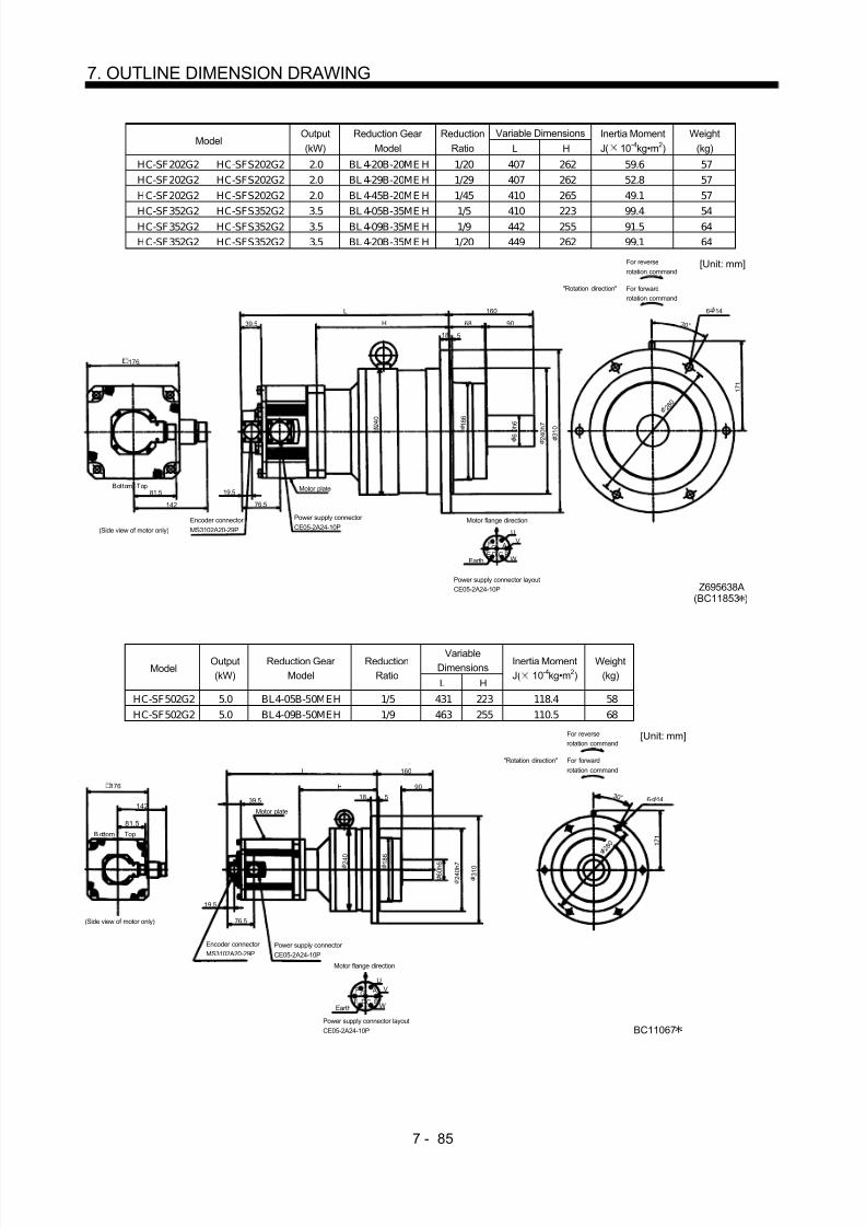
8/10/2019 Servo Motor - Instruction Manual SH(NA)-3181-D (03.00)
http://slidepdf.com/reader/full/servo-motor-instruction-manual-shna-3181-d-0300 164/368
7 - 85
7. OUTLINE DIMENSION DRAWING
Variable DimensionsModel
Output(kW)
Reduction Gear Model
ReductionRatio L H
Inertia MomentJ( 10 -4kg•m 2)
Weight(kg)
HC-SF202G2 HC-SFS202G2 2.0 BL 4-20B-20ME H 1/20 407 262 59.6 57HC-SF202G2 HC-SFS202G2 2.0 BL 4-29B-20ME H 1/29 407 262 52.8 57HC-SF202G2 HC-SFS202G2 2.0 BL 4-45B-20ME H 1/45 410 265 49.1 57
HC-SF352G2 HC-SFS352G2 3.5 BL 4-05B-35ME H 1/5 410 223 99.4 54HC-SF352G2 HC-SFS352G2 3.5 BL 4-09B-35ME H 1/9 442 255 91.5 64HC-SF352G2 HC-SFS352G2 3.5 BL 4-20B-35ME H 1/20 449 262 99.1 64
160
5
81.5 19.5
1 7 1
3 0 °
UV
WCD BE
AGF
90
18
76.5
68
L
H39.5
142
Encoder connector MS3102A20-29P
Power supply connector CE05-2A24-10P
Power supply connector layoutCE05-2A24-10P
Motor plate
Earth
Motor flange direction
[Unit: mm]
Bottom Top
(Side view of motor only)
"Rotation direction"
For reverserotation command
For forwardrotation command
Z695638A(BC11853 )
176
6- 14
2 8 0
6 0 h 6
2 4 0 h 7
3 1 0 1 8 6
2 4 0
VariableDimensionsModel
Output(kW)
Reduction Gear Model
ReductionRatio
L H
Inertia MomentJ( 10 -4kg•m 2)
Weight(kg)
HC-SF502G2 5.0 BL4-05B-50MEH 1/5 431 223 118.4 58HC-SF502G2 5.0 BL4-09B-50MEH 1/9 463 255 110.5 68
Power supply connector layoutCE05-2A24-10P
142
L
H
160
Motor plate
19.5
1 7 1
Motor flange direction
UV
WCD BE
AGF
Earth
Encoder connector MS3102A20-29P
Power supply connector CE05-2A24-10P
81.5
76.5
18 5
90
39.53 0 °
B ottom Top
(Side view of motor only)
[Unit: mm]
"Rotation direction"
For reverserotation command
For forwardrotation command
2 4 0
1 8 6
6 0 h 6
2 4 0 h 7
3 1 0
6- 14
2 8 0
BC11067
176

8/10/2019 Servo Motor - Instruction Manual SH(NA)-3181-D (03.00)
http://slidepdf.com/reader/full/servo-motor-instruction-manual-shna-3181-d-0300 165/368
7 - 86
7. OUTLINE DIMENSION DRAWING
ModelOutput(kW)
Reduction Gear Model
ReductionRatio
Inertia MomentJ( 10 -4kg•m 2)
Weight(kg)
HC-SF702G2 7.0 BL4-05B-70MEH 1/5 177.4 67
Power supply connector layoutCE05-2A32-17P
150
515
223
160
Motor plate
19.5
1 7 1
[Unit: mm]
Motor flange direction
U
V
WCD
B
AEarth
Encoder connector MS3102A20-29P
Power supply connector CE05-2A32-17P
81.5
81.5
18 5
90
39.5 3 0 °
94
Bottom Top
(Side view of motor only)
BC11068
176 6- 14
2 8 0
6 0 h 6
2 4 0 h 7
3 1 0 2 4 0
1 8 6
(b) With electromagnetic brakeVariable
DimensionsModelOutput(kW)
Reduction Gear Model
ReductionRatio
Inertia MomentJ( 10 -4kg•m 2)
L H
Braking Force(N•m)
Weight(kg)
HC-SF52BG2 HC-SFS52BG2 0.5 BL2-05B-05MEH 1/5 9.6 309 156 8.5 15HC-SF52BG2 HC-SFS52BG2 0.5 BL2-09B-05MEH 1/9 9.25 321 168 8.5 15HC-SF52BG2 H C-SFS52BG2 0.5 BL2-20B-05MEH 1/20 9.73 342 189 8.5 17
HC-SF102BG2 HC-SFS102BG2 1.0 BL2-05B-10MEH 1/5 16.7 334 156 8.5 17HC-SF102BG2 HC-SFS102BG2 1.0 BL2-09B-10MEH 1/9 16.3 346 168 8.5 17HC-SF152BG2 HC-SFS152BG2 1.5 BL2-05B-15MEH 1/5 22.9 359 156 8.5 19
L
39.5
19.5
101.5
H 43 55
100
4 5 °
W
VU
AF G
H BEC
D
111
81.5 12 3
Encoder connector MS3102A20-29P Power supply connector
CE05-2A22-23P
Power supply connector layout(CE05-2A22-23P)
Motor plate
Earth
Motor flange direction
[Unit: mm]
Bottom Top(Side view of motor only)
"Rotation direction"
For reverserotation command
For forwardrotation command
Brake
3 5 h 6
9 4
1 3 0 h 7
4- 12
1 6 0
130 140
(BC11856 )Z695323
1 8 5

8/10/2019 Servo Motor - Instruction Manual SH(NA)-3181-D (03.00)
http://slidepdf.com/reader/full/servo-motor-instruction-manual-shna-3181-d-0300 166/368
7 - 87
7. OUTLINE DIMENSION DRAWING
Variable DimensionsModel
Output(kW)
Reduction Gear Model
ReductionRatio
Inertia MomentJ( 10 -4kg•m 2) L H
Braking Force(N•m)
Weight(kg)
HC-SF52BG2 HC-SFS52BG2 0.5 BL3-29B-05MEH 1/29 11.1 370 217 8.5 32HC-SF52BG2 HC-SFS52BG2 0.5 BL3-45B-05MEH 1/45 10.1 376 223 8.5 32
HC-SF102BG2 HC-SFS102BG2 1.0 BL 3-20B-10ME H 1/20 20.1 395 217 8.5 34
HC-SF102BG2 HC-SFS102BG2 1.0 BL 3-29B-10ME H 1/29 18.2 395 217 8.5 34HC-SF152BG2 HC-SFS152BG2 1.5 BL3-09B-15MEH 1/9 26.4 412 209 8.5 36HC-SF152BG2 HC-SFS152BG2 1.5 BL 3-20B-15ME H 1/20 26.3 420 217 8.5 36
W
VU
AF G
H BEC
D
L
39.5
140
63 75
111
81.5
15 5
H
19.5
101.5
1 3 7
3 0 °
Encoder connector MS3102A20-29P
Power supply connector CE05-2A22-23P
Power supply connector layoutCE05-2A22-23P
Motor plate
Earth
Motor flange direction
[Unit: mm]
B ot tom Top(Side view of motor only)
"Rotation direction"
For reverserotation command
For forwardrotation command
Brake
(BC11857 )Z695324
130
1 9 0 1 3 5
5 0 h 6
1 9 0 h 7
2 4 5
2 2 0
6- 12
Variable DimensionsModel
Output(kW)
Reduction Gear Model
ReductionRatio
Inertia MomentJ( 10 -4kg•m 2) L H
Braking Force(N•m)
Weight(kg)
HC-SF102BG2 HC-SFS102BG2 1.0 BL 4-45B-10ME H 1/45 22.0 422 244 8.5 54HC-SF152BG2 HC-SFS152BG2 1.5 BL 4-29B-15ME H 1/29 32.0 444 241 8.5 56HC-SF152BG2 HC-SFS152BG2 1.5 BL 4-45B-15ME H 1/45 28.2 447 244 8.5 56
W
VU
AF GHBEC
D
L
39.5
160
68 90
111
81.5
18 5
H
19.5
101.5
1 7 1
3 0 °
Encoder connector MS3102A20-29P Power supply connector
CE05-2A22-23P
Power supply connector layoutCE05-2A22-23P
Motor plate
Earth
Motor flange direction
[Unit: mm]
Bot tom Top(Side view of motor only)
"Rotation direction"
For reverserotation command
For forwardrotation command
Brake
6 0 h 6
2 4 0 h 7
3 1 0
1 8 6
2 8 0
6- 14
(BC11858 )Z695325
130

8/10/2019 Servo Motor - Instruction Manual SH(NA)-3181-D (03.00)
http://slidepdf.com/reader/full/servo-motor-instruction-manual-shna-3181-d-0300 167/368
7 - 88
7. OUTLINE DIMENSION DRAWING
Variable DimensionsModel
Output(kW)
Reduction Gear Model
ReductionRatio L H
Braking Force(N•m)
Inertia MomentJ( 10 -4kg•m 2)
Weight(kg)
HC-SF202BG2 HC-SFS202BG2 2.0 BL3-05B-20MEH 1/5 396 203 43.1 59.6 36HC-SF202BG2 HC-SFS202BG2 2.0 BL3-09B-20MEH 1/9 423 230 43.1 57.2 43
140
5
81.5
19.5
1 3 7
3 0 °
UV
WCD BE
AGF
75
15
69
63
L
H39.5
142124.5
A B
117
Encoder connector MS3102A20-29P
Power supply connector CE05-2A24-10P
Power supply connector layoutCE05-2A24-10P
Earth
Brake connector MS3102A10SL-4P
Motor flange direction
Brake
Brake connector layoutMS3102A10SL-4P
Motor flange direction
Motor plate
[Unit: mm]
(Side view of motor only)
"Rotation direction"
For reverserotation command
For forwardrotation command
Z695640A(BC11859 )
6- 12
2 2 0
1 9 0
5 0 h 6
1 3 5
1 9 0 h 7
2 4 5
Variable DimensionsModel
Output(kW)
Reduction Gear Model
ReductionRatio L H
Braking Force(N•m)
Inertia MomentJ( 10 -4kg•m 2)
Weight(kg)
HC-SF202BG2 HC-SFS202BG2 2.0 BL 4-20B-20ME H 1/20 455 262 43.1 69.6 63HC-SF202BG2 HC-SFS202BG2 2.0 BL 4-29B-20ME H 1/29 455 262 43.1 62.8 63
HC-SF202BG2 HC-SFS202BG2 2.0 BL 4-45B-20ME H 1/45 458 265 43.1 59.1 63HC-SF352BG2 HC-SFS352BG2 3.5 BL4-05B-35MEH 1/5 458 223 43.1 109.4 60HC-SF352BG2 HC-SFS352BG2 3.5 BL4-09B-35MEH 1/9 490 255 43.1 101.5 70HC-SF352BG2 HC-SF S352BG2 3.5 BL 4-20B-35ME H 1/20 497 262 43.1 109.1 70
160
5
81.5
19.5
1 7 1
3 0 °
UV
WCD BE AGF
90
18
124.5
68
L
H39.5
69
117
142
AB
Encoder connector MS3102A20-29P
Power supply connector CE05-2A24-10P
Power supply connector layoutCE05-2A24-10P
Earth
Brake connector MS3102A10SL-4P
Motor flange direction
Brake
Brake connector layoutMS3102A10SL-4P
Motor flange direction
Motor plate
[Unit: mm]
(Side view of motor only)
"Rotation direction"
For reverserotation command
For forwardrotation command
Bottom Top
2 4 0
6 0 h 6
2 4 0 h 7
3 1 0 1 8 6
6- 14
2 8 0
Z695641A(BC11860 )
176

8/10/2019 Servo Motor - Instruction Manual SH(NA)-3181-D (03.00)
http://slidepdf.com/reader/full/servo-motor-instruction-manual-shna-3181-d-0300 168/368
7 - 89
7. OUTLINE DIMENSION DRAWING
VariableDimensionsModel
Output(kW)
Reduction Gear Model
ReductionRatio
L H
Inertia MomentJ( 10 -4kg•m 2)
Weight(kg)
HC-SF502BG2 5.0 BL4-05B-50MEH 1/5 479 223 124.5 64HC-SF502BG2 5.0 BL4-09B-50MEH 1/9 511 255 124.5 74
Power supply connector layoutCE05-2A24-10P
142
L
H
160
117 Motor plate
19.5
69
1 7 1
Motor flange direction
UV
WCD BE
AGF
Earth
Encoder connector
MS3102A20-29PPower supply connector CE05-2A24-10P
81.5
Brake connector layoutMS3102A10SL-4P
Motor flange direction
B ABrake
124.5
Brake connector MS3102A10SL-4P 18 5
90
39.5
3 0 °
(Side view of motor only)
[Unit: mm]
"Rotation direction"
For reverserotation command
For forwardrotation command
Bottom Top
BC11069
176
2 4 0
1 8 6
6 0 h 6
2 4 0 h 7
3 1 0
6- 14
2 8 0
ModelOutput(kW)
Reduction Gear Model
ReductionRatio
Inertia MomentJ( 10 -4kg•m 2)
Weight(kg)
HC-SF702BG2 7.0 BL 4-05B-70ME H 1/5 187.4 73
Power supply connector layoutCE05-2A32-17P
150
563
223
160
117Motor plate
19.5
69
1 7 1
Motor flange direction
U
V
WCD
B
AEarth
Encoder connector MS3102A20-29P Power supply
connector CE05-2A32-17P
81.5
Brake connector layoutMS3102A10SL-4P
Motor flange direction
B ABrake
129.5
Brake connector MS3102A10SL-4P 18 5
9039.5
3 0 °
94
(Side view of motor only)
[Unit: mm]
Bottom Top
2 4 0
1 8 6
6 0 h 6
2 4 0 h 7
3 1 0
2 8 0
6- 14
BC11070
176

8/10/2019 Servo Motor - Instruction Manual SH(NA)-3181-D (03.00)
http://slidepdf.com/reader/full/servo-motor-instruction-manual-shna-3181-d-0300 169/368
7 - 90
7. OUTLINE DIMENSION DRAWING
7.1.4 HC-RF•HC-RFS Series
(1) Standard (without electromagnetic brake, without reduction gear)Variable Dimensions
ModelOutput(kW)
Inertia MomentJ( 10 -4kg•m 2) L KL
Weight(kg)
HC-RF103 HC-RFS103 1.0 1.5 147 71 3.9HC-RF153 HC-RFS153 1.5 1.9 172 96 5.0HC-RF203 HC-RFS203 2.0 2.3 197 121 6.2
41
9 6
4 5 °
8 1 . 5
19.5
MS3102A20-29P CE05-2A22-23P W
VU
AFG
H BEC
D
KL
L
39.5 10 3
40
S30457B
2 4 h 6
45
Bottom
Top
Encoder connector Power supply connector
Oil seal
Motor flange direction
Earth
Power supply connector layout(CE05-2A22-23P)
[Unit: mm]
Use hexagon socket head cap screw.
Motor plate
(Opposite side)
Bottom
Top 9 5 h 7
1 1 5 1 3 5
100
4- 9 mounting hole
Z694853(BC11697 )
Variable DimensionsModel
Output(kW)
Inertia MomentJ( 10 -4kg•m 2) L KL
Weight(kg)
HC-RF353 3.5 8.6 217 148 12HC-RF503 5.0 12.0 274 205 17
[Unit: mm]
58Motor plate
Earth
V
U
WD C
B
AGF
E
1 2 0
Power supply connector layoutCE05-2A24-10P
Motor flange direction
3
63
1239.5
2 8 h 6
Top
Bottom
L
(Opposite side)
Oil seal
S30457B
Bottom
Top
8 1 . 5
19.5
4 5 °
46
KL
Power supply connector
CE05-2A24-10P
Encoder connector
MS3102A20-29P
1 1 0 h 7
1 6 5
1 4 5
4- 9 mounting holeUse hexagon sockethead cap screw.
130
Z695780

8/10/2019 Servo Motor - Instruction Manual SH(NA)-3181-D (03.00)
http://slidepdf.com/reader/full/servo-motor-instruction-manual-shna-3181-d-0300 170/368
7 - 91
7. OUTLINE DIMENSION DRAWING
(2) With electromagnetic brakeVariable Dimensions
ModelOutput(kW)
Inertia MomentJ( 10 -4kg•m 2) L KL
Braking Force(N•m)
Weight(kg)
HC-RF103B HC-RFS103B 1.0 1.85 185 71 7 6.0HC-RF153B HC-RFS153B 1.5 2.25 210 96 7 7.0HC-RF203B HC-RFS203B 2.0 2.65 235 121 7 8.3
Bottom
KL19.5
W
VU
MS3102A20-29P CE05-2A22-23P
8 1 . 5 S30457B
L 45
10 3
40
AF
G
H BEC
D 41
9 6
4 5 °
Bottom
Top
Encoder connector Power supply connector
Oil seal
Motor flange direction
Earth
Power supply connector layout(CE05-2A22-23P)
[Unit: mm]
(Use hexagon socket head cap screw.)
Motor plate
(Opposite side)
Top
Brake
100
4- 9 mounting hole
1 1 5
1 3 5
2 4 h 6
9 5 h 7
Z695165(BC11699 )
Variable DimensionsModel
Output(kW)
Inertia MomentJ( 10 -4kg•m 2) L KL
Braking Force(N•m)
Weight(kg)
HC-RF353B 3.5 11.8 274 148 16.7 15HC-RF503B 5.0 15.5 314 205 16.7 21
Encoder connector
Power supply connector
19.5
EarthW
VU
A
B
CD
E
FG
Power supply connector layoutCE05-2A24-10P
Motor flange direction
MS3102A20-29P
CE05-2A24-10P
8 1 . 5
L 63
12 3
58
46
1 2 0
Bottom
4 5 °
[Unit: mm]
Bottom
39.5
S30457B
Brake
KL
Oil seal
TopTop
Motor plate(Opposite side)
1304- 9 mounting holeUse hexagon sockethead cap screw.
1 4 5
1 6 5
Z695563
2 8 h 6
1 1 0 h 7

8/10/2019 Servo Motor - Instruction Manual SH(NA)-3181-D (03.00)
http://slidepdf.com/reader/full/servo-motor-instruction-manual-shna-3181-d-0300 171/368
7 - 92
7. OUTLINE DIMENSION DRAWING
(3) With reduction gear for precision application(a) Without electromagnetic brake
Variable DimensionsModel
Output(kW)
Reduction Gear Model
ReductionRatio
Inertia MomentJ( 10 -4kg•m 2) L H
Weight(kg)
HC-RF 103G2 HC-RF S103G2 1.0 BL 2-05B-10M EK D 1/5 4.95 301 154 11.9HC-RF 103G2 HC-RF S103G2 1.0 BL 2-09B-10M EK D 1/9 4.6 313 166 11.9HC-RF 153G2 HC-RF S153G2 1.5 BL 2-05B-15ME KD 1/5 5.35 326 154 13HC-RF 203G2 HC-RF S203G2 2.0 BL 2-05B-20M EK D 1/5 5.75 351 154 14.2
L
39.5
100
19.5
76
81.5
96
H
12 3
43 55
4 5 °
W
VU
AFGH
BEC
D
3 5 h 6
140
Z695327A
Encoder connector MS3102A20-29P
Power supply connector CE05-2A22-23P
Power supply connector layout(CE05-2A22-23P)
Earth
Motor flange direction
[Unit: mm]
Bot tom Top
(Side view of motor only)
"Rotation direction"
For reverserotation command
For forwardrotation command
Motor plate(Opposite side)
9 4
1 3 0 h 7 1 3 2
1 8 5 1 6 0
4- 12
100
Variable DimensionsModel
Output(kW)
Reduction Gear Model
ReductionRatio
Inertia MomentJ( 10 -4kg•m 2) L H LI
Weight(kg)
H C-RF 103G2 H C-RF S103G2 1.0 BL 3-20B -10M E KD 1/20 8.35 354 207 105 28.9H C-RF 103G2 H C-RF S103G2 1.0 BL 3-29B -10M E KD 1/29 6.45 354 207 105 28.9H C-RF 103G2 H C-RF S103G2 1.0 BL 3-45B -10M E KD 1/45 5.48 364 217 115 28.9H C-RF 153G2 H C-RF S153G2 1.5 BL 3-09B-15M EK D 1/9 6.68 375 203 101 30H C-RF 153G2 H C-RF S153G2 1.5 BL 3-20B-15M EK D 1/20 8.75 379 207 105 30H C-RF 153G2 H C-RF S153G2 1.5 BL 3-29B-15M EK D 1/29 6.85 379 207 105 30H C-RF 203G2 H C-RF S203G2 2.0 BL 3-09B-20M EK D 1/9 9.08 400 203 101 31.2H C-RF 203G2 H C-RF S203G2 2.0 BL 3-20B -20M E KD 1/20 9.15 404 207 105 31.2
W
VU
AF G
H BE
C
D
L
39.5
140
63 75
96
81.5
15 5
H
19.5
76
3 0 °
LI
Encoder connector MS3102A20-29P
Power supply connector CE05-2A22-23P
Power supply connector layout(CE05-2A22-23P)
Earth
Motor flange direction
[Unit: mm]
Bottom Top
(Side view of motor only)
"Rotation direction"
For reverserotation command
For forwardrotation command
(Opposite side)Motor plate
1 9 0 1 3 5
5 0 h 6
1 9 0 h 7
2 4 5
2 2 0
1 3 6 . 5
6- 12
Z695328
100

8/10/2019 Servo Motor - Instruction Manual SH(NA)-3181-D (03.00)
http://slidepdf.com/reader/full/servo-motor-instruction-manual-shna-3181-d-0300 172/368
7 - 93
7. OUTLINE DIMENSION DRAWING
Variable DimensionsModel
Output(kW)
Reduction Gear Model
ReductionRatio
Inertia MomentJ( 10 -4kg•m 2) L H LI
Weight(kg)
H C-RF 153G2 H C-RF S153G2 1.5 BL 4-45B-15M EK D 1/45 8.55 410 238 136 50H C-RF 203G2 H C-RF S203G2 2.0 B L4-29B-20M E KD 1/29 12.7 425 228 126 51.2H C-RF 203G2 H C-RF S203G2 2.0 BL 4-45B -20M E KD 1/45 8.98 435 238 136 51.2
W
VU
AFGH
BE
CD
L
39.5
160
68 90
96
81.5
18 5
H
19.5
76
3 0 °
LI
1 7 1
Encoder connector MS3102A20-29P Power supply connector
CE05-2A22-23P
Power supply connector layout(CE05-2A22-23P)
Earth
Motor flange direction
[Unit: mm]
Bottom Top
Side view of motor only)
"Rotation direction"
For reverserotation command
For forwardrotation command
(Opposite side)Motor plate
100
2 4 0
1 8 6
2 4 0 h 7
3 1 0
6 0 h 6
6- 14
2 8 0
Z695329(BC11865 )
ModelOutput
(kW)
Reduction Gear
Model
Reduction
Ratio
Inertia Moment
J( 10-4
kg•m2)
Weight
(kg)HC-RF 353G2 3.5 BL 3-05B-35ME KD 1/5 18.8 30
Earth W
VU
Motor flange direction
AFGBE CD
Encoder connector MS3102A20-29P
Power supply connector CE05-2A24-10P
Bottom Top
418
39.5
63
140
75
81.5
120
15 5
201
Motor plate19.5
69.5
2 4 5
For reverserotation command
For forwardrotation command
"Rotation direction"
1 3 6 . 5
3 0 °
74
[Unit: mm]
Power supply connector layout(CE05-2A24-10P)
(Side view of motor only)
Z695990
130
1 9 0
5 0 h 6
1 9 0 h 7 1 3 5
6- 12
2 2 0

8/10/2019 Servo Motor - Instruction Manual SH(NA)-3181-D (03.00)
http://slidepdf.com/reader/full/servo-motor-instruction-manual-shna-3181-d-0300 173/368
7 - 94
7. OUTLINE DIMENSION DRAWING
Variable DimensionsModel
Output(kW)
Reduction Gear Model
ReductionRatio L H LI
Inertia MomentJ( 10 -4kg•m 2)
Weight(kg)
HC-RF353G2 3.5 BL4-09B-35MEKD 1/9 470 253 126 21.1 57HC-RF353G2 3.5 BL4-20B-35MEKD 1/20 470 253 126 28.8 57HC-RF353G2 3.5 BL4-29B-35MEKD 1/29 470 253 126 22.0 57
HC-RF503G2 5.0 BL4-05B-50MEKD 1/5 495 221 94 32.4 52HC-RF503G2 5.0 BL4-09B-50MEKD 1/9 527 253 126 24.5 62HC-RF503G2 5.0 BL4-20B-50MEKD 1/20 527 253 126 32.2 62
Earth W
VU
Motor flange direction
AFGBE CD
Encoder connector MS3102A20-29P
Power supply connector CE05-2A24-10P
Bottom Top
L
39.5
68
160
90
81.5
120
18 5
H
Motor plate19.5
69.5
1 7 1
LI
[Unit: mm]For reverserotation command
For forwardrotation command
"Rotation direction"
Power supply connector layout(CE05-2A24-10P)
(Side view of motor only)
2 4 0
1 8 6
2 4 0 h 7 6 0 h 6
3 1 0
6- 14
2 8 0
Z695992
130
3 0 °
(b) With electromagnetic brakeVariable
DimensionsModelOutput(kW)
Reduction Gear Model
ReductionRatio
Inertia MomentJ( 10 -4kg•m 2)
L H
Braking Force(N•m)
Weight(kg)
HC-RF103BG2 HC-RFS103BG2 1.0 BL2-05B-10MEK D 1/5 5.3 339 154 7 14HC-RF103BG2 HC-RFS103BG2 1.0 BL2-09B-10MEK D 1/9 4.95 351 166 7 14HC-RF 153BG2 HC-RFS153BG2 1.5 BL 2-05B-15MEK D 1/5 5.7 364 154 7 15.1HC-RF 203BG2 HC-RFS203BG2 2.0 BL 2-05B-20MEK D 1/5 6.1 389 154 7 16.3
L
39.5
100
19.5
113.5
81.5
96
H
12 3
43 55
1 3 0 h 7
4 5 °
W
VU
A
FG
H BECD
Encoder connector MS3102A20-29P
Power supply connector CE05-2A22-23P
Power supply connector layout(CE05-2A22-23P)
Earth
Motor flange direction
[Unit: mm]
Bot tom Top
(Side view of motor only)
"Rotation direction"
For reverserotation command
For forwardrotation command
(Opposite side)Motor plate
Brake
100
1404- 12
1 8 5 1 6 0
3 5 h 6
9 4 1 3 2
Z695330(BC11868 )

8/10/2019 Servo Motor - Instruction Manual SH(NA)-3181-D (03.00)
http://slidepdf.com/reader/full/servo-motor-instruction-manual-shna-3181-d-0300 174/368

8/10/2019 Servo Motor - Instruction Manual SH(NA)-3181-D (03.00)
http://slidepdf.com/reader/full/servo-motor-instruction-manual-shna-3181-d-0300 175/368
7 - 96
7. OUTLINE DIMENSION DRAWING
ModelOutput(kW)
Reduction Gear Model
ReductionRatio
Braking Force(N•m)
Inertia MomentJ( 10 -4kg•m 2)
Weight(kg)
HC-RF353BG2 3.5 BL3-05B-35MEKD 1/5 16.7 20.8 33
Earth W
VU
Power supply connector layoutCE05-2A24-10P
Motor flange direction
AF GBE CD
Encoder connector MS3102A20-29P
Power supply connector CE05-2A24-10P
Bottom Top
455
39.5
63
140
75
81.5
120
(Side view of motor only)
15 5
201
Motor plate19.5
106
For reverserotation command
For forwardrotation command
"Rotation direction"
1 3 6 . 5
3 0 °
74
Brake
[Unit: mm]
130
Z695991
6- 12
2 2 0
1 3 5 1 9 0
1 9 0 h 7
5 0 h 6
2 4 5
Variable DimensionsModel
Output(kW)
Reduction Gear Model
ReductionRatio L H LI
Braking Force(N•m)
Inertia MomentJ( 10 -4kg•m 2)
Weight(kg)
HC-RF353BG2 3.5 BL4-09B-35MEKD 1/9 507 253 126 16.7 23.1 60HC-RF353BG2 3.5 BL4-20B-35MEKD 1/20 507 253 126 16.7 30.8 60HC-RF353BG2 3.5 BL4-29B-35MEKD 1/29 507 253 126 16.7 22.0 60HC-RF503BG2 5.0 BL4-05B-50MEKD 1/5 532 221 94 16.7 34.4 56HC-RF503BG2 5.0 BL4-09B-50MEKD 1/9 564 253 126 16.7 26.5 66HC-RF503BG2 5.0 BL4-20B-50MEKD 1/20 564 253 126 16.7 34.2 66
Earth W
VU
Motor flange direction
AF GBE CD
Encoder connector MS3102A20-29P
Power supply connector CE05-2A24-10P
Bottom Top
L
39.5
68
160
90
81.5
120
18 5
H
Motor plate19.5
106
1 7 1
3 0 °
LI
Brake
[Unit: mm]
For forwardrotation command
For reverse
rotation command"Rotation direction"
(Side view of motor only)
Power supply connector layoutCE05-2A24-10P
6 0 h 6
2 4 0 h 7
1 8 6
2 4 0
3 1 0
2 8 0
6- 14
Z695993
130

8/10/2019 Servo Motor - Instruction Manual SH(NA)-3181-D (03.00)
http://slidepdf.com/reader/full/servo-motor-instruction-manual-shna-3181-d-0300 176/368
7 - 97
7. OUTLINE DIMENSION DRAWING
7.1.5 HC-UF 2000r/min•HC-UFS 2000r/min Series
(1) Standard (without electromagnetic brake)
ModelOutput(kW)
Inertia MomentJ( 10 -4kg•m 2)
Weight(kg)
HC-UF72 HC-UFS72 0.75 10.4 8
Top
Encoder connector
MS3102A20-29P
Power supplyconnector CE05-2A22-23P
Motor flange direction
Power supply connector layoutCE05-2A22-23P
A
BC
DE
F G
U
V
WEarth
Oil seal
S30457B
2-M6 screw
4 0 °
4 5 °
39.555
13 3
Bottom
Top
19.5
8 1 . 5
1 4 4
[Unit: mm]
44H
38
110.5
50
0 – 0 . 0 2 5
Bottom
Motor plate
(Opposite side)
2 2 h 6
1 1 4 . 3
2 3 0
2 0 0
2 1 5
4- 13.5 mounting holeUse hexagon sockethead cap screw.
176
Z695911(BC11711 )
ModelOutput(kW)
Inertia MomentJ( 10 -4kg•m 2)
Weight(kg)
HC-UF152 HC-UFS152 1.5 22.1 11
Top
Bottom
Encoder connector
MS3102A20-29P
Power supplyconnector CE05-2A22-23P
Motor flange direction
Power supply connector layout CE05-2A22-23P
A
BCD
EF
G
U
V
WEarth
Oil seal
S30457B
Motor plate(Opposite side) 2-M6 screw
4 0 °
4 5 °
39.555
13 3
Bottom
Top
19.5
8 1 . 5
1 4 4
[Unit: mm]
44
H47.5
120
50
1 1 4 . 3 0 –
0 . 0 2 5
2 8 h 6
2 3 0
2 1 5
2 0 0
176
4- 13.5 mounting holeUse hexagon sockethead cap screw.
Z695912A(BC11712 )

8/10/2019 Servo Motor - Instruction Manual SH(NA)-3181-D (03.00)
http://slidepdf.com/reader/full/servo-motor-instruction-manual-shna-3181-d-0300 177/368
7 - 98
7. OUTLINE DIMENSION DRAWING
Variable DimensionsModel
Output(kW) L KL
Inertia MomentJ( 10 -4kg•m 2)
Weight(kg)
HC-UF202 HC-UFS202 2.0 118 42.5 38.2 16HC-UF352 HC-UFS352 3.5 142 66.5 76.5 20HC-UF502 5.0 166 90.5 115 24
Top
Bottom
Encoder connector
MS3102A20-29P
Power supply connector CE05-2A24-10P
Motor flange direction
Power supply connector layoutCE05-2A24-10P
A
BCDE
FG
U
V
W
Oil seal
S40608B
2-M8 screw
3 7. 5 °
4 5 °
39.565
16 4
Bottom
Top
19.5
8 1 . 5
1 6 4
[Unit: mm]
47
KL
L
60
0 – 0 . 0 4 6
2 0 0
3 5 h 6
2 7 0
2 3 5
2 5 0
220
4- 13.5 mounting holeUse hexagon sockethead cap screw.
Z695914(BC11713 )
(2) With electromagnetic brakeModel Output(kW) Braking Force(N•m) Inertia Moment J( 10 -4kg•m 2) Weight(kg)
HC-UF72B HC-UFS72B 0.75 8.5 12.4 10
Top
Bottom
Encoder connector
MS3102A20-29P
Power supplyconnector CE05-2A22-23P
Motor flange direction
Power supply connector layoutCE05-2A22-23P
A
BCDEF
G
U
V
WEarth
Oil seal
S30457B
Motor plate
2-M6 screw
4 0 °
4 5 °
39.5
55
13 3
Bottom
Top
19.5
1 4 4
[Unit: mm]
44H
38
144
Brake
0 – 0 . 0 2 5
(Opposite side)
4- 13.5 mounting holeUse hexagon sockethead cap screw.
2 3 0
2 0 0
2 1 5
176
2 2 h 6
1 1 4 . 3
Z695981A(BC11714 )

8/10/2019 Servo Motor - Instruction Manual SH(NA)-3181-D (03.00)
http://slidepdf.com/reader/full/servo-motor-instruction-manual-shna-3181-d-0300 178/368
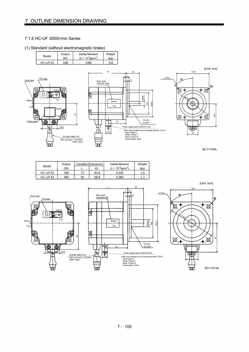
8/10/2019 Servo Motor - Instruction Manual SH(NA)-3181-D (03.00)
http://slidepdf.com/reader/full/servo-motor-instruction-manual-shna-3181-d-0300 179/368

8/10/2019 Servo Motor - Instruction Manual SH(NA)-3181-D (03.00)
http://slidepdf.com/reader/full/servo-motor-instruction-manual-shna-3181-d-0300 180/368
7 - 101
7. OUTLINE DIMENSION DRAWING
ModelOutput
(W)Inertia MomentJ( 10 -4kg•m 2)
Weight(kg)
HC-UF73 750 5.9 5.0
BC11357A26.9
7 2
85 40
2.5
10 4 5 ° 3.5
32.5
20
7 6
55.5
70
[Unit: mm]
Oil sealSC20357
Encoder cable 0.3m
With connector 1-172169-9(AMP make)
Power supply lead 4-AWG19 0.3m
Motor plate(Opposite side)
Bottom
Top
(With end-insulated round crimping terminal 1.25-4) Red: Phase U White: Phase V Black: Phase W
Green/yellow: Earth
Motor plate
8 0 1 1 0 h 7
1 9 h 6
123
1 4 5
1 6 5
4- 9
TUV plate
Cautionplate
Bottom
Top
BottomTop
(2) With electromagnetic brake
ModelOutput
(W)Braking Force
(N•m)Inertia MomentJ( 10 -4kg•m 2)
Weight(kg)
HC-UF13B 100 0.32 0.074 1.2
4 2 . 8
[Unit: mm]
BC11767A
Motor plate(Opposite side)
Encoder cable 0.3m
Power supply lead 4-AWG19 0.3m26.9
4 0
With connector 1-172169-9(AMP make)
(With end-insulated round crimping terminal 1.25-4) Red: Phase U White: Phase V Black: Phase W Green/yellow: Earth
Oil sealSC10207
100 25
3
5
Bottom
Top
4 5 °
R 5
6
Brake cableTough-rubber sheath cable 2-0.75 0.3m(With end-insulated round crimping terminal 1.25-4)
2
4 0 5 0 h 7
8 h 6
4- 5.8
60
7 0
20
TUV plateMotor plate
Cautionplate
Bottom
Top
Bottom
Top
Bottom
Top
46.733
9.9
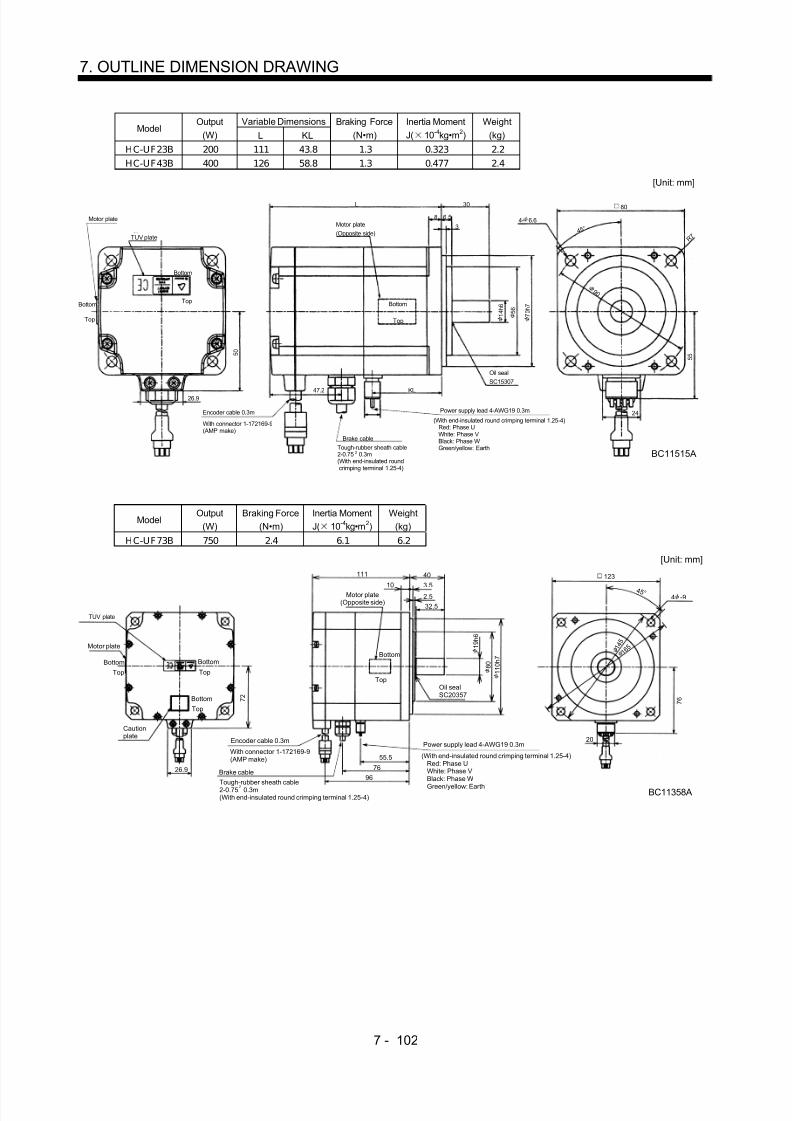
8/10/2019 Servo Motor - Instruction Manual SH(NA)-3181-D (03.00)
http://slidepdf.com/reader/full/servo-motor-instruction-manual-shna-3181-d-0300 181/368
7 - 102
7. OUTLINE DIMENSION DRAWING
Variable DimensionsModel
Output(W) L KL
Braking Force(N•m)
Inertia MomentJ( 10 -4kg•m 2)
Weight(kg)
HC-UF23B 200 111 43.8 1.3 0.323 2.2HC-UF43B 400 126 58.8 1.3 0.477 2.4
[Unit: mm]
BC11515A
Motor plate(Opposite side)
Encoder cable 0.3m Power supply lead 4-AWG19 0.3m
26.9
5 0
With connector 1-172169-9(AMP make)
(With end-insulated round crimping terminal 1.25-4) Red: Phase U White: Phase V Black: Phase W Green/yellow: Earth
Oil sealSC15307
L 30
3
8
Bottom
Top
4 5 °
R 7
6.5
Brake cable
2
TUV plate
Motor plate
Bottom
Top
47.2 KL
1 4 h 6 5 6
7 0 h 7
4- 6.6
80
9 0
5 5
24
Bottom
Top
Tough-rubber sheath cable2-0.75 0.3m(With end-insulated roundcrimping terminal 1.25-4)
ModelOutput
(W)Braking Force
(N•m)Inertia MomentJ( 10 -4kg•m 2)
Weight(kg)
HC-UF73B 750 2.4 6.1 6.2
111
26.9
1 4 5
4 5 ° 10
BC11358A
7 2
40
32.5
3.5
2.5
1 6 5
7 6
20
55.5
7696
Oil sealSC20357
Encoder cable 0.3m
With connector 1-172169-9(AMP make)
Brake cable
Power supply lead 4-AWG19 0.3m
[Unit: mm]
Motor plate(Opposite side)
(With end-insulated round crimping terminal 1.25-4) Red: Phase U White: Phase V Black: Phase W Green/yellow: Earth
Bottom
Top
Motor plate
Cautionplate
TUV plate
1 9 h 6
1 1 0 h 7 8 0
123
4 -9
BottomBottom
Top
Bottom
Top
Top
2Tough-rubber sheath cable2-0.75 0.3m(With end-insulated round crimping terminal 1.25-4)

8/10/2019 Servo Motor - Instruction Manual SH(NA)-3181-D (03.00)
http://slidepdf.com/reader/full/servo-motor-instruction-manual-shna-3181-d-0300 182/368
7 - 103
7. OUTLINE DIMENSION DRAWING
(3) IP65-compliant (without electromagnetic brake)
ModelOutput
(W)Inertia MomentJ( 10 -4kg•m 2)
Weight(kg)
HC-UF13-S1 100 0.066 0.8
4 0
26.9
70
7 0
4 5 °5
BC11292A
25
3
3
14
33
5 0
8 7
24
1234
123456789
10
MRMRRBATMD
MDR
R 5
[Unit: mm]
Power supplyconnector pinconnection list
Pin No. ApplicationPhase UPhase VPhase W
EarthEncoder connector pin connection list
Pin No. Application
Bottom
Top
Oil sealS10207
Encoder cable 0.3m
Power supply cable 0.3m
Motor plate(Opposite side)
With connector RM15WTP-10P,cord clamp RM15WTP-CP7(Hirose Electric make) With connector RM15WTP-4P,
cord clamp RM15WTP-CP8(Hirose Electric make)
CNTP5LGSD
8 h 6
4 0 5 0 h 7
4- 5.8
60
Variable DimensionsModel
Output(W) L KL
Inertia MomentJ( 10 -4kg•m 2)
Weight(kg)
HC-UF23-S1 200 75 44 0.241 1.5HC-UF43-S1 400 90 59 0.365 1.7
5 0
26.9
L
4 5 °8
BC11293A
30
3
3.5
14
KL
R 7
6 0
9 7
24
1234
Power supplyconnector pinconnection list
Pin No. ApplicationPhase UPhase VPhase W
Earth
Encoder connector pin connection list
[Unit: mm]
Bottom
Top
Oil sealS15307
Encoder cable 0.3mPower supply cable 0.3m
Motor plate(Opposite side)
With connector RM15WTP-10P,cord clamp RM15WTP-CP7(Hirose Electric make)
With connector RM15WTP-4P,cord clamp RM15WTP-CP8(Hirose Electric make)
123456789
10
MRMRRBATMD
MDR
Pin No. Application
CNTP5LGSD
5 6 7 0 h 7
1 4 h 6
4- 6.6
80
9 0

8/10/2019 Servo Motor - Instruction Manual SH(NA)-3181-D (03.00)
http://slidepdf.com/reader/full/servo-motor-instruction-manual-shna-3181-d-0300 183/368
7 - 104
7. OUTLINE DIMENSION DRAWING
ModelOutput
(W)Inertia MomentJ( 10 -4kg•m 2)
Weight(kg)
HC-UF73-S1 750 5.9 5.0
7 2
26.9
85
4 5 ° 10
BC11359A
40
3.5
32.5
8 1 . 5
1 1 8 . 5
24
14
55.5
2.5
[Unit: mm]
Bottom
TopOil sealS20357
Encoder cable 0.3m
Power supply cable 0.3m
Motor plate(Opposite side)
With connector RM15WTP-10P,cord clamp RM15WTP-CP7(Hirose Electric make)
With connector RM15WTP-4P,cord clamp RM15WTP-CP8(Hirose Electric make)
1234
12345678
910
MRMRRBATMD
MDR
Power supplyconnector pinconnection list
Pin No. ApplicationPhase UPhase VPhase W
EarthEncoder connector pin connection list
Pin No. Application
CNTP5LG
SD
1 9 h 6
8 0 1 1 0 h 7
4- 9
123
1 4 5
1 6 5
(4) IP65-compliant, with electromagnetic brake
ModelOutput
(W)Braking Force
(N•m)Inertia MomentJ( 10 -4kg•m 2)
Weight(kg)
HC-UF13B-S1 100 0.32 0.074 1.2
4 0
26.9
100
4 5 °5
BC11295A
25
33
R 5
5 0
8 7
24
14
3346.5
[Unit: mm]
Bottom
Top
Oil sealS10207
Encoder cable 0.3m
Brake cable 0.3m
Power supply cable 0.3m
Power supplyconnector pinconnection list
1234
Pin No. ApplicationB1B2
Encoder connector pin connection list
Brake connector pinconnection list
1234
Pin No. ApplicationPhase UPhase VPhase W
Earth
Motor plate(Opposite side)
With connector RM15WTP-10P,cord clamp RM15WTP-CP7(Hirose Electric make)
With connector RM15WTP-4P,cord clamp RM15WTP-CP6(Hirose Electric make)
With connector RM15WTP-4P,cord clamp RM15WTP-CP8(Hirose Electric make)
123456
789
10
MRMRRBATMD
MDR
Pin No. Application
CNT
P5LGSD
5 0 h 7 4 0
8 h 6
80
4- 5.8
7 0

8/10/2019 Servo Motor - Instruction Manual SH(NA)-3181-D (03.00)
http://slidepdf.com/reader/full/servo-motor-instruction-manual-shna-3181-d-0300 184/368
7 - 105
7. OUTLINE DIMENSION DRAWING
Variable DimensionsModel
Output(W) L KL
Braking Force(N•m)
Inertia MomentJ( 10 -4kg•m 2)
Weight(kg)
HC-UF23-S1 200 109 44 1.3 0.323 2.2HC-UF43-S1 400 124 59 1.3 0.447 2.4
5 0
26.9
L
4 5 °8
BC11296A
30
3
3.5 R 7
6 0
9 7
24
14
KL
45.3
Power supplyconnector pinconnection list
1234
Pin No. ApplicationB1B2
Encoder connector pin connection list
Brake connector pinconnection list
1234
Pin No. ApplicationPhase UPhase VPhase W
Earth
[Unit: mm]
Bottom
Top
Oil sealS15307
Encoder cable 0.3m
Brake cable 0.3m
Power supply cable 0.3m
Motor plate(Opposite side)
With connector RM15WTP-10P,cord clamp RM15WTP-CP7(Hirose Electric make)
With connector RM15WTP-4P,cord clamp RM15WTP-CP6(Hirose Electric make)
With connector RM15WTP-4P,cord clamp RM15WTP-CP8(Hirose Electric make)
1
23456789
10
MR
MRRBATMD
MDR
Pin No. Application
CNTP5LGSD
1 4 h 6 5 6
7 0 h 7
4- 6.6
80
9 0
ModelOutput
(W)Braking Force
(N•m)Inertia MomentJ( 10 -4kg•m 2)
Weight(kg)
HC-UF73B-S1 750 2.4 6.1 6.2
1114 5 °
10
BC11360A
40
3.5
32.5
8 1 . 5
1 1 8 . 5
24
1 4 5
14
55.5
35
2.5
1 6 5
[Unit: mm]
Bottom
TopOil sealS20357
Brake cable 0.3m
Power supply cable 0.3m
Motor plate(Opposite side)
Motor plate(Opposite side)
4 0
26.9
7 2
Encoder cable 0.3m
With connector RM15WTP-10P,cord clamp RM15WTP-CP7(Hirose Electric make)
With connector RM15WTP-4P,cord clamp RM15WTP-CP6(Hirose Electric make)
With connector RM15WTP-4P,cord clamp RM15WTP-CP8(Hirose Electric make)
Power supplyconnector pinconnection list
1234
Pin No. ApplicationB1B2
Encoder connector pin connection list
Brake connector pinconnection list
1234
Pin No. ApplicationPhase UPhase VPhase W
Earth
123456789
10
MRMRRBATMD
MDR
Pin No. Application
CNTP5LGSD
1 0 h 7 8 0
1 9 h 6
123
4- 9

8/10/2019 Servo Motor - Instruction Manual SH(NA)-3181-D (03.00)
http://slidepdf.com/reader/full/servo-motor-instruction-manual-shna-3181-d-0300 185/368
7 - 106
7. OUTLINE DIMENSION DRAWING
7.1.7 HA-LH series
Variable DimensionsModel
F L LA LB LC LD LG LT KL KH IE IF Hanger E LR Q SOil Seal
HA-LH11K2(-Y) 208 529 215 180 250 204 20 316 478 102 152 317 M10 3 85 80 42h6 S45629BHA-LH15K2(-Y) 578 362 527
HA-LH22K2(-Y)254
643265 230 300 250 25
430 592117 180 376 M12 5 110 100 55m6 S608295
[Unit: mm]
5
77
I F
I E
164
5
Encoder connector MS3102A20-29P
Oil seal
ELG
LR
K H
L
KL
LT
Q
Cooling fan
Hangers in 3 places
Exhaust air
Suction air
(Note)
Note: When using the motor without the hangers, plug the screw holes with the following bolts: HA-LH11K2: M10 15mm max. HA-LH15K2, 22K2: M12 18mm max.
1 200V 50/60Hz
L C
L B h 7
S
F
LD4- 14.5
L A
Terminal Box of HA-LH11K2 to 22K 2Power Connection Screw Size
Servo Motor Power Connection Screw Size
HA-LH11K2 8-6HA-LH15K2•22K2 14-6
146
2 0 9
Ground terminalM5 screw
3 power leads (U, V, W)with round crimping terminals
Encoder cableMS3102A20-29P
Cooling fan leads(BU,BV)Round crimping
terminal 1.25-4
[Unit: mm]
4 4
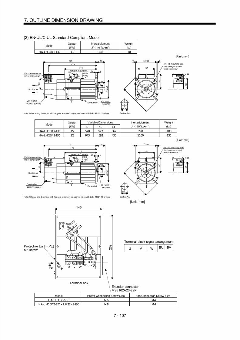
8/10/2019 Servo Motor - Instruction Manual SH(NA)-3181-D (03.00)
http://slidepdf.com/reader/full/servo-motor-instruction-manual-shna-3181-d-0300 186/368
7 - 107
7. OUTLINE DIMENSION DRAWING
(2) EN•UL/C-UL Standard-Compliant Model
ModelOutput(kW)
Inertia MomentJ( 10 -4kg•m 2)
Weight(kg)
HA-LH11K2-EC 11 118 70
4- 14.5 mounting holeUse hexagon sockethead cap screw.164
77
1 0 2
3 1 7
1 5 2
[Unit: mm]
Note: When using the motor with hangers removed, plug screw holes with bolts M10 15 or less.
Encoder connector MS3102A20-29P
Oil sealS45629B
320
85
1 0 2
529
478
316
A
A
80
Cooling fan
Hangers in 3 places
Exhaust air
Suction air
(M10)(Note)
2 0 8
1 200V 50/60Hz
1 8 0 h 7
Section AA
42h6
44
2 1 52 5 0
204
Variable DimensionsModel
Output(kW) L KL LT
Inertia MomentJ( 10 -4kg•m 2)
Weight(kg)
HA-LH15K2-EC 15 578 527 362 290 108HA-LH22K2-EC 22 643 592 430 1160 135
S60829B
525
110
1 1 7
L
KL
LT
2 5 4 A
A
100
Note: When u sing the motor with hangers removed, plug screw holes with bolts M12 18 or less.
Encoder connector MS3102A20-29P
Oil sealCooling fan
Hangers in 3 places
Exhaust air
Suction air
(M12)(Note)
1 200V 50/60Hz
2 3 0 h 7
Section AA
55m6
164
77
1 1 7
3 7 6
1 8 0
Use hexagon sockethead cap screw.
[Unit: mm]250
44
4- 14.5 mounting hole
2 6 53 0 0
146
Terminal box
BU BVU V W
Terminal block signal arrangement
[Unit: mm]
Protective Earth (PE)M5 screw
Encoder connector MS3102A20-29P
2 0 9
U V WBUBV 4 4
Model Power Connection Screw Size Fan Connection Screw Size
HA-L H11K2-EC M6 M4HA-L H15K2-EC • LH22K2-EC M8 M4

8/10/2019 Servo Motor - Instruction Manual SH(NA)-3181-D (03.00)
http://slidepdf.com/reader/full/servo-motor-instruction-manual-shna-3181-d-0300 187/368
7 - 108
7. OUTLINE DIMENSION DRAWING
7.1.8 HC-AQ series
(1) Standard (without electromagnetic brake)Variable Dimensions
ModelOutput
(W) LInertia MomentJ( 10 -4kg•m 2)
Weight(kg)
HC-AQ0135D 10 54 0.0050 0.19HC-AQ0235D 20 63 0.0072 0.22HC-AQ0335D 30 70 0.0094 0.25
5
2 1
4 5 °
0 . 5
A
A
10
16
2.5
L200 + 200
26.5
MRRLG
WV
MRP5SD
UE
12
7
6
1
BC11340A
[Unit: mm]
Arrow C
Power supply lead
Arrow C Section A-A
Connector 5557-12R-210(Molex make) UL94V-0
U: RedV: WhiteW: BlackEarth: GreenB1, B2 6h6
2 0 h 7
2- 2.9mounting hole
3 3
28
(2) With electromagnetic brakeVariable Dimensions
ModelOutput
(W) LInertia MomentJ( 10 -4kg•m 2)
Weight(kg)
HC-AQ0135BD 10 82 0.0073 0.29AC-AQ0235BD 20 89 0.0095 0.32HC-AQ0335BD 30 96 0.0117 0.35
2 1
4 5 °
16
2.5
L200 + 200
26.5
MRRLG
B1WV
MRP5SDB2UE
12
7
6
1
A
A
10
0 . 5
BC11343A
[Unit: mm]
Arrow C
Power supply lead/brake lead
Arrow C Section A-A
Connector 5557-12R-210(Molex make) UL94V-0
U: RedV: WhiteW: BlackEarth: GreenB1, B2
6h6
2- 2.9mounting hole
2 0 h 7
3 3
28
5

8/10/2019 Servo Motor - Instruction Manual SH(NA)-3181-D (03.00)
http://slidepdf.com/reader/full/servo-motor-instruction-manual-shna-3181-d-0300 188/368
7 - 109
7. OUTLINE DIMENSION DRAWING
7.1.9 HA-LF series
Terminal box detail diagram
Motor Model HA-LF30K24
HA-LF37K24
HA-LF45K24HA-LF55K24HA-LF30K2
Motor power supplylead size
8mm 2 2parallel
22mm 2 2parallel
Motor power supplyterminal block screwsize
M8 M10
LA 220 266 Terminal boxdimensions(mm) LB 210 230
LA
L B
BG71994B
Motor power supplylead
Encoder connector MS3102A20-29P
[Unit: mm]
Motor power supplyterminal block(U, V, W)
Cooling fan terminal block(BU, BV, BW) M4 screw
Thermal protector terminal block(OHS1, OHS2) M4 screw
Earth terminalM5 screw
Cooling fan lead0.9SQ or equivalent
Thermal protector lead0.5SQ or equivalent
ModelOutput(kW)
Inertia MomentJ( 10 -4kg•m 2)
Weight(kg)
HA-LF 30K 24 30 550 160
6 6286
22011 27
1 5 2
605
128 426 140
140
1 7 9
105 105
260
108
4- 15
25 5
386
25 8
4 5 °
2 3 0
2 0
55
127
310
127
1 6 0
0 - 0 . 5
BC10833
[Unit: mm]
Cooling fanrotation direction
Suction air
Encoder connector MS3102A20-29P
Hanger
(Note)Exhaust air
Oil sealS659013B
M12 screw
4- 19Use hexagon sockethead cap screw.
Note: When the motor is used without the hanger, plug the threaded hole with a bolt of M16 20mm or less.
51
6 0 m 6
2 5 0 h 7 3 0
0
280

8/10/2019 Servo Motor - Instruction Manual SH(NA)-3181-D (03.00)
http://slidepdf.com/reader/full/servo-motor-instruction-manual-shna-3181-d-0300 189/368
7 - 110
7. OUTLINE DIMENSION DRAWING
ModelOutput(kW)
Inertia MomentJ( 10 -4kg•m 2)
Weight(kg)
HA-LF37K 24 37 650 180
6 6286
22011 27
1 5 2
650128 471 140
140
1 7 9
127 127
304
108
25 5
431
25 8
4 5 °
2 3 0
2 0
55
127
310
127
1 6 0 0 - 0 .
5
BC10788C
[Unit: mm]
Cooling fanrotationdirection
Suction air
Encoder connector MS3102A20-29P
Hanger (Note)
Exhaust air
Oil sealS659013B
M12 screw
4- 19Use hexagon sockethead cap screw.
Note: When the motor is used without the hanger, plug the threaded hole with a bolt of M16 20mm or less.
51
4- 15
6 0 m 6
2 5 0 h 7
280
3 0 0
ModelOutput(kW)
Inertia MomentJ( 10 -4kg•m 2)
Weight(kg)
HA-LF45K 24 45 1080 230
6 6352
26611 27
1 8 4
640
138 439 140
140
2 1 6
101.5 101.5
262
121
25 5
399
30 9
4 5 °
2 8 0
2 2
70139.5
349
139.5
1 8 0 0 - 0 .
5
BC11107A
[Unit: mm]
Cooling fanrotationdirection Suction air
Encoder connector MS3102A20-29P
Hanger (Note)
Exhaust air
Oil sealS709513B
M16 screw
4- 19Use hexagon sockethead cap screw.
Note: When the motor is used without the hanger, plug the threaded hole with a bolt of M16 20mm or less.
63
4- 19
6 5 m 6
3 0 0 h 7 3 5
0
350

8/10/2019 Servo Motor - Instruction Manual SH(NA)-3181-D (03.00)
http://slidepdf.com/reader/full/servo-motor-instruction-manual-shna-3181-d-0300 190/368

8/10/2019 Servo Motor - Instruction Manual SH(NA)-3181-D (03.00)
http://slidepdf.com/reader/full/servo-motor-instruction-manual-shna-3181-d-0300 191/368
7 - 112
7. OUTLINE DIMENTION DRAWING
7.1.10 HC-MFS•HC-KFS series
(1) Standard (without electromagnetic brake, without reduction gear)Variable Dimensions
ModelOutput
(W) L KLInertia MomentJ( 10 -4kg•m 2)
Weight(kg)
HC-MFS053 50 81.5 29.5 0.019 0.40HC-MFS13 100 96.5 44.5 0.03 0.53HC-KFS053 50 81.5 29.5 0.053 0.40HC-KFS13 100 96.5 44.5 0.084 0.53
Power supplyconnector pinconnection list
123
4
Pin No.
RedWhiteBlackGreen/yellow
Application
Phase UPhase VPhase W
Earth
Lead wirecolor
[Unit: mm]
BC11873(BC11879 )
20
5557-04R-210 (Receptacle)5556PBTL (Female terminal)
With connector 1-172169-9(AMP maker)
Arrow A
4 5 °
3 5 . 7
Bottom
Top
Protective tube
Motor plate(Opposite side)
3 0 h 7
4 6
40
8 h 6
Logo plate
Power supply connector (Molex make)
Encoder cable 0.3m
Motor plate
Caution plate
Bottom
Top
Bottom
Top
KL
25
2.55
L
40.5
6.8
9.925.2
42
2 8 . 7
2- 4.5
Power supply lead 4-AWG19 0.3m
TUV plate
Arrow A
Bottom
TopTop
Bottom
1
2 4
3
Variable DimensionsModel
Output(W) L KL
Inertia MomentJ( 10 -4kg•m 2)
Weight(kg)
HC-MFS23 200 99.5 49.1 0.088 0.99
HC-MFS43 400 124.5 72.1 0.143 1.45HC-KFS23 200 99.5 49.1 0.42 0.99HC-KFS43 400 124.5 72.1 0.67 1.45
Power supplyconnector pinconnection list
123
4
Pin No.
RedWhiteBlackGreen/yellow
Application
Phase UPhase VPhase W
Earth
Lead wirecolor
[Unit: mm]
BC11874(BC11880 )
20
5557-04R-210 (Receptacle)5556PBTL (Female terminal)
With connector 1-172169-9(AMP maker)
Arrow A
4 5 °
4 2 . 8
Bottom
Top
Protective tube
Motor plate(Opposite side)
5 0 h 7
7 0
60
1 4 h 6
Logo plate
Power supply connector (Molex make)
Encoder cable 0.3m
Motor plate
Caution plate
Bottom
Top
KL
3037
L
41
10.6 9.925.2
62
3 8 . 4
4- 5.8
Power supply lead 4-AWG19 0.3m
TUV plate
Arrow A
Top
Bottom
Top
Bottom
2.7
12
34
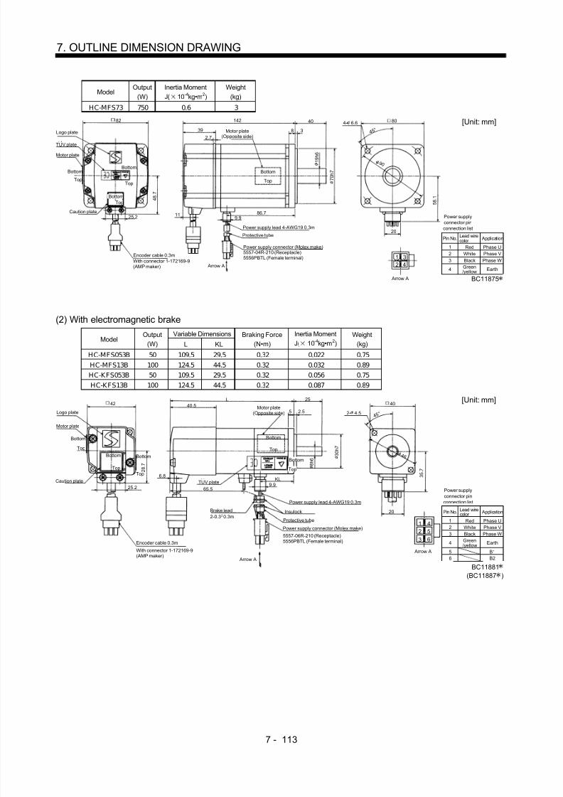
8/10/2019 Servo Motor - Instruction Manual SH(NA)-3181-D (03.00)
http://slidepdf.com/reader/full/servo-motor-instruction-manual-shna-3181-d-0300 192/368
7 - 113
7. OUTLINE DIMENSION DRAWING
ModelOutput
(W)Inertia MomentJ( 10 -4kg•m 2)
Weight(kg)
HC-MFS73 750 0.6 3
Power supplyconnector pinconnection list
123
4
Pin No.
RedWhiteBlackGreen/yellow
Application
Phase UPhase VPhase W
Earth
Lead wirecolor
[Unit: mm]
BC11875
20
5557-04R-210 (Receptacle)5556PBTL (Female terminal)
With connector 1-172169-9(AMP maker)
Arrow A
4 5 °
5 8 . 1
Bottom
Top
Protective tube
Motor plate(Opposite side)
7 0 h 7
9 0
80
1 9 h 6
Logo plate
Power supply connector (Molex make)
Encoder cable 0.3m
Motor plate
Caution plate
Bottom
Top
86.7
40
38
142
39
119.925.2
82
4 8 . 7
4- 6.6
Power supply lead 4-AWG19 0.3m
TUV plate
Arrow A
Top
Bottom
TopBottom
2.7
12
34
(2) With electromagnetic brakeVariable Dimensions
ModelOutput
(W) L KLBraking Force
(N•m)
Inertia MomentJ( 10 -4kg•m 2)
Weight(kg)
HC-MFS053B 50 109.5 29.5 0.32 0.022 0.75HC-MFS13B 100 124.5 44.5 0.32 0.032 0.89HC-KFS053B 50 109.5 29.5 0.32 0.056 0.75HC-KFS13B 100 124.5 44.5 0.32 0.087 0.89
Power supplyconnector pinconnection list
123
4
Pin No.
RedWhiteBlackGreen/yellow
Application
Phase UPhase VPhase W
Earth
Lead wirecolor
5
6
B1
B2
[Unit: mm]
BC11881(BC11887 )
20
5557-06R-210 (Receptacle)5556PBTL (Female terminal)
Arrow A
4 5 °
3 5 . 7
Bottom
Top
Protective tube
Motor plate(Opposite side)
3 0 h 7
4 6
40
8 h 6
Logo plate
Power supply connector (Molex make)
Encoder cable 0.3m
Motor plate
Caution plate
Bottom
Top
Bottom
TopKL
25
2.55
L40.5
6.8
9.925.2
42
2 8 . 7
2- 4.5
Power supply lead 4-AWG19 0.3m
TUV plate
Arrow A
Bottom
TopTop
Bottom
Brake lead2-0.3 0.3m2
Insulock
12
45
3 6
65.5
With connector 1-172169-9(AMP maker)

8/10/2019 Servo Motor - Instruction Manual SH(NA)-3181-D (03.00)
http://slidepdf.com/reader/full/servo-motor-instruction-manual-shna-3181-d-0300 193/368
7 - 114
7. OUTLINE DIMENSION DRAWING
Variable DimensionsModel
Output(W) L KL
Braking Force(N•m)
Inertia MomentJ( 10 -4kg•m 2)
Weight(kg)
HC-MFS23B 200 131.5 49.1 1.3 0.136 1.6HC-MFS43B 400 156.5 72.1 1.3 0.191 2.1HC-KFS23B 200 131.5 49.1 1.3 0.47 1.6
HC-KFS43B 400 156.5 72.1 1.3 0.72 2.1
Power supplyconnector pinconnection list
12
34
Pin No.
RedWhite
BlackGreen/yellow
Application
Phase UPhase V
Phase WEarth
Lead wirecolor
56
B1B2
[Unit: mm]
BC11882(BC11888 )
20
5557-06R-210 (Receptacle)5556PBTL (Female terminal)
With connector 1-172169-9(AMP maker) Arrow A
4 5 °
4 2 . 8
Bottom
Top
Protective tube
Motor plate(Opposite side)
5 0 h 7
7 0
60
1 4 h 6
Logo plate
Power supply connector (Molex make)
Encoder cable 0.3m
Motor plate
Caution plate
Bottom
Top
KL
3037
L
41
10.6
9.925.2
62
3 8 . 4
4- 5.8
Power supply lead 4-AWG19 0.3m
TUV plate
Arrow A
Top
Bottom
Top
Bottom
2.7
68
InsulockBrake lead2-0.3 0.3m2
1
2
4
5
3 6
ModelOutput
(W)Brake Static Friction
Torque (N•m)
Inertia MomentJ( 10 -4kg•m 2)
Weight(kg)
HC-MFS73B 750 2.4 0.725 4.0
5557-06R-210 (Receptacle)5556PBTL (Female terminal)
Power supplyconnector pinconnection list
123
4
Pin No.
RedWhiteBlackGreen/yellow
Application
Phase UPhase VPhase W
Earth
Lead wirecolor
56
B1B2
[Unit: mm]
BC11883
20
With connector 1-172169-9(AMP maker)
Arrow A
4 5 °
5 8 . 1
Bottom
Top
Protective tube
Motor plate(Opposite side)
7 0 h 79 0
80
1 9 h 6
Logo plate
Power supply connector (Molex make)
Encoder cable 0.3m
Motor plate
Caution plate
Bottom
Top
86.7
40
38
177.5
39
119.925.2
82
4 8 . 7
4- 6.6
Power supply lead 4-AWG19 0.3m
TUV plate
Arrow A
Top
Bottom
TopBottom
2.7
72
Brake lead2-0.3 0.3m2
Insulock
1
2
4
5
3 6

8/10/2019 Servo Motor - Instruction Manual SH(NA)-3181-D (03.00)
http://slidepdf.com/reader/full/servo-motor-instruction-manual-shna-3181-d-0300 194/368
7 - 115
7. OUTLINE DIMENSION DRAWING
(3) With reduction gear for general industrial machine(a) Without electromagnetic brake
Variable DimensionsModel
Output(W) L KL
ReductionGear Model
Reduction Ratio(Actual Reduction Ratio)
Inertia MomentJ( 10 -4kg•m 2)
BacklashWeight
(kg)
HC-MFS053G1 50 126 74 K6505 1/5(9/44) 0.055 60min. max. 1.4HC-MFS053G1 50 144 92 K6512 1/12(49/576) 0.077 60min. max. 1.8HC-MFS053G1 50 144 92 K6520 1/20(25/484) 0.059 60min. max. 1.8HC-KFS053G1 50 126 74 K6505 1/5(9/44) 0.090 60min. max. 1.4HC-KFS053G1 50 144 92 K6512 1/12(49/576) 0.112 60min. max. 1.8HC-KFS053G1 50 144 92 K6520 1/20(25/484) 0.094 60min. max. 1.8
Bottom
Power supplyconnector pinconnection list
123
4
Pin No.
RedWhiteBlackGreen/yellow
Application
Phase UPhase VPhase W
Earth
Lead wirecolor
[Unit: mm]
BC11896(BC11924 )
20
5557-04R-210 (Receptacle)5556PBTL (Female terminal)
With connector 1-172169-9(AMP maker)
4 5 °
3 5 . 7
Bottom
Top
Protective tube
Motor plate(Opposite side)
6 0 h 7
7 5
65
1 6 h 6
Logo plate
Power supply connector (Molex make)
Encoder cable 0.3m
Motor plate
Caution plate
Bottom
Top
KL
60.5
6.58
L
40.5
6.89.925.2
42
2 8 . 7
4- 7
Power supply lead 4-AWG19 0.3m
TUV plate
Arrow A
TopTop
Bottom
28 25
4 8
8 8
For reverse rotation command
For forward rotation command"Rotation direction"
M4 threads,depth 8
Arrow A
1
2
3
4
Bottom
Top
Variable DimensionsModel
Output(W) L KL
ReductionGear Model
Reduction Ratio(Actual Reduction Ratio)
Inertia MomentJ( 10 -4kg•m 2)
BacklashWeight
(kg)
HC-MFS13G1 100 141 89 K6505 1/5(9/44) 0.067 60min. max. 1.5HC-MFS13G1 100 159 107 K6512 1/12(49/576) 0.089 60min. max. 1.9HC-MFS13G1 100 159 107 K6520 1/20(25/484) 0.071 60min. max. 1.9HC-KFS13G1 100 141 89 K6505 1/5(9/44) 0.121 60min. max. 1.5HC-KFS13G1 100 159 107 K6512 1/12(49/576) 0.143 60min. max. 1.9HC-KFS13G1 100 159 107 K6520 1/20(25/484) 0.125 60min. max. 1.9
Bottom
Power supplyconnector pinconnection list
123
4
Pin No.
RedWhiteBlackGreen/yellow
Application
Phase UPhase VPhase W
Earth
Lead wirecolor
[Unit: mm]
BC11897(BC11925 )
20
5557-04R-210 (Receptacle)5556PBTL (Female terminal)
With connector 1-172169-9(AMP maker) Arrow A
4 5 °
3 5 . 7
Bottom
Top
Protective tube
Motor plate(Opposite side)
6 0 h 7
7 5
65
1 6 h 6
Logo plate
Power supply connector (Molex make)
Encoder cable 0.3m
Motor plate
Caution plate
Bottom
Top
KL
60.5
6.58
L
40.5
6.8
9.925.2
42
2 8 . 7
4- 7
Power supply lead 4-AWG19 0.3m
TUV plate
Arrow A
TopTop
Bottom
28 25
4 8
8 8
For reverse rotation command
For forward rotation command"Rotation direction"
M4 threads,depth 8
1
2
3
4
Bottom
Top

8/10/2019 Servo Motor - Instruction Manual SH(NA)-3181-D (03.00)
http://slidepdf.com/reader/full/servo-motor-instruction-manual-shna-3181-d-0300 195/368
7 - 116
7. OUTLINE DIMENSION DRAWING
Variable DimensionsModel
Output(W) L KL
ReductionGear Model
Reduction Ratio(Actual Reduction Ratio)
Inertia MomentJ( 10 -4kg•m 2)
Weight(kg)
HC-MFS23G1 200 153 102.6 K9005 1/5(19/96) 0.249 3.3HC-MFS23G1 200 173 122.6 K9012 1/12(25/288) 0.293 3.9HC-MFS23G1 200 173 122.6 K 9020 1/20(253/5000) 0.266 3.9
HC-KFS23G1 200 153 102.6 K9005 1/5(19/96) 0.58 3.3HC-KFS23G1 200 173 122.6 K9012 1/12(25/288) 0.63 3.9HC-KFS23G1 200 173 122.6 K9020 1/20(253/5000) 0.60 3.9
Power supplyconnector pinconnection list
123
4
Pin No.
RedWhiteBlackGreen/yellow
Application
Phase UPhase VPhase W
Earth
Lead wirecolor
[Unit: mm]
BC11898(BC11926 )
20
5557-04R-210 (Receptacle)5556PBTL (Female terminal)With connector 1-172169-9
(AMP maker)
Arrow A
4 5 °
Protective tube
Motor plate(Opposite side)
90
2 5 h 6
Logo plate
Power supply connector (Molex make)Encoder cable 0.3m
Motor plate
Cautionplate
Bottom
Top
Bottom
Top
KL
74
810
L
10.625.2
62
3 8 . 4
Power supply lead 4-AWG19 0.3m
Arrow A
Bottom
TUV plate
BottomTop
Top
4 2 . 8
9.9
2.7
4130 35
7 3 8 2 h 7
1
2
3
4
For reverse rotation command
For forward rotation command"Rotation direction"
1 1 4 1 0
0
4- 9
M6 threads,depth 12
Variable DimensionsModel
Output(W) L KL
ReductionGear Model
Reduction Ratio(Actual Reduction Ratio)
Inertia MomentJ( 10 -4kg•m 2)
Weight(kg)
HC-MFS43G1 400 178 125.6 K9005 1/5(19/96) 0.296 3.8
HC-MFS43G1 400 198 145.6 K9012 1/12(25/288) 0.339 4.4HC-KFS43G1 400 178 125.6 K9005 1/5(19/96) 0.82 3.8HC-KFS43G1 400 198 145.6 K9012 1/12(25/288) 0.87 4.4
Power supplyconnector pinconnection list
123
4
Pin No.
RedWhiteBlackGreen/yellow
Application
Phase UPhase VPhase W
Earth
Lead wirecolor
[Unit: mm]
BC11899(BC11927 )
20
5557-04R-210 (Receptacle)5556PBTL (Female terminal)With connector 1-172169-9
(AMP maker)
Arrow A
4 5 °
Protective tube
Motor plate(Opposite side)
90
2 5 h 6
Logo plate
Power supply connector (Molex make)Encoder cable 0.3m
Motor plate
Cautionplate
Bottom
Top
Bottom
Top
KL
74
810
L
10.625.2
62
3 8 . 4
Power supply lead 4-AWG19 0.3m
Arrow A
Bottom
TUV plate
BottomTop
Top
4 2 . 8
9.9
2.7
41 30 35
7 3 8 2 h 7
1
2
3
4
For reverse rotation command
For forward rotation command"Rotation direction"
1 1 4 1 0
0
4- 9
M6 threads,depth 12

8/10/2019 Servo Motor - Instruction Manual SH(NA)-3181-D (03.00)
http://slidepdf.com/reader/full/servo-motor-instruction-manual-shna-3181-d-0300 196/368
7 - 117
7. OUTLINE DIMENSION DRAWING
Reduction RatioModel
Output(W)
Reduction Gear Model Normal Reduction ratio Actual Reduction Ratio
Inertia MomentJ( 10 -4kg•m 2)
BacklashWeight
(kg)
HC-MFS43G1 400 K10020 1/20 253/5000 0.653 60min. max. 5.5HC-MFS73G1 750 K10005 1/5 1/5 1.02 60min. max. 6.2HC-MFS73G1 750 K10012 1/12 525/6048 1.686 60min. max. 7.3
HC-MFS73G1 750 K12020 1/20 625/12544 1.75 60min. max. 10.1
Variable DimensionsModel
Output
(W) D LH LK LT H LA LB LC LD LE LF LG LM LN LP L LR KL LZ Q S P R
(Reduction
Ratio)
HC-MFS43G1 400 62 38.4 41 10.6 42.8 115 95 132 100 10 73 10 13 16 86 201.5 90 149.1 9 50 32 M8 16 1/20
HC-MFS73G1 750 82 48.7 39 11 58.1 115 95 132 100 10 73 10 13 16 86 207 90 151.7 9 50 32 M 8 16 1/5
HC-MFS73G1 750 82 48.7 39 11 58.1 115 95 132 100 10 73 10 13 16 86 229 90 173.7 9 50 32 M8 16 1/12
HC-MFS73G1 750 82 48.7 39 11 58.1 140 115 162 120 12 90 15 13 20 104 242 106 186.7 14 60 40 M 10 20 1/20
Power supplyconnector pinconnection list
123
4
Pin No.
RedWhiteBlackGreen/yellow
Application
Phase UPhase VPhase W
Earth
Lead wirecolor
[Unit: mm]
BC11900
20
5557-04R-210 (Receptacle)5556PBTL (Female terminal)
With connector 1-172169-9(AMP maker) Arrow A
4 5 °
Protective tube
Motor plate(Opposite side)
LD
S h 6
Logo plate
Power supply connector (Molex make)
Encoder cable 0.3m
Motor plate
Cautionplate
BottomTop
Bottom
Top
KL
LRL
LT25.2
D
Power supply lead 4-AWG19 0.3m
Arrow A
TUV plate
Bottom
Top
9.9
2.7
LKLG
L F
1
2
3
4
For reverse rotation command
For forward rotation command
"Rotation direction"
L C L A
4- LZ
P threads,depth R
BottomTop
L H
H
LE
LM LN Q
L P L B h 7
Reduction RatioModel
Output(W)
Reduction Gear Model Normal Reduction ratio Actual Reduction Ratio
Inertia MomentJ( 10 -4kg•m 2)
BacklashWeight
(kg)
HC-KFS43G1 400 K10020 1/20 253/5000 1.18 60min. max. 5.5
Power supplyconnector pinconnection list
123
4
Pin No.
RedWhiteBlackGreen/yellow
Application
Phase UPhase VPhase W
Earth
Lead wirecolor
[Unit: mm]
20
5557-04R-210 (Receptacle)5556PBTL (Female terminal)
With connector 1-172169-9(AMP maker) Arrow A
4 5 °
Protective tube
Motor plate(Opposite side)
100Logo plate
Power supply connector (Molex make)
Encoder cable 0.3m
Motor plate
Cautionplate
BottomTop
Bottom
Top
149.1
90201.5
10.625.2
62
Power supply lead 4-AWG19 0.3m
Arrow A
TUV plate
Bottom
Top
9.9
2.7
4110
7 3
1
2
3
4
For reverse rotation command
For forward rotation command
"Rotation direction"
1 3 2 1 1
5
4- 9
M8 threads,depth 16
BottomTop
3 8 . 4
4 2 . 8
10
13 1 6 50
8 6 9 5 h 7
3 2 h 6

8/10/2019 Servo Motor - Instruction Manual SH(NA)-3181-D (03.00)
http://slidepdf.com/reader/full/servo-motor-instruction-manual-shna-3181-d-0300 197/368
7 - 118
7. OUTLINE DIMENSION DRAWING
(b) With electromagnetic brakeVariable Dimensions
ModelOutput
(W) L KLBraking Force
(N•m)Reduction
Gear ModelReduction
RatioInertia MomentJ( 10 -4kg•m 2)
BacklashWeight
(kg)
HC-MFS053BG1 50 154 74 0.32 K6505 1/5(9/44) 0.058 60min. max. 1.8HC-MFS053BG1 50 172 92 0.32 K 6512 1/12(49/576) 0.080 60min. max. 2.2HC-MFS053BG1 50 172 92 0.32 K 6520 1/20(25/484) 0.062 60min. max. 2.2HC-KFS053BG1 50 154 74 0.32 K6505 1/5(9/44) 0.093 60min. max. 1.8HC-KFS053BG1 50 172 92 0.32 K 6512 1/12(49/576) 0.115 60min. max. 2.2HC-KFS053BG1 50 172 92 0.32 K 6520 1/20(25/484) 0.097 60min. max. 2.2
Power supplyconnector pinconnection list
123
4
Pin No.
RedWhiteBlackGreen/yellow
Application
Phase UPhase VPhase W
Earth
Lead wirecolor
56
B1B2
BC11901(BC11929 )
[Unit: mm]
20
5557-06R-210 (Receptacle)5556PBTL (Female terminal)
With connector 1-172169-9(AMP maker)
Arrow A
4 5 °
Protective tube
Motor plate(Opposite side)
65Logo plate
Power supply connector (Molex make)
Encoder cable 0.3m
Motor plate
Cautionplate
Bottom
Top
Bottom
Top
60.5L
6.8
25.2
42
Arrow A
TUV plate9.9
40.58
1
2
4
5
For reverse rotation command
For forward rotation command
"Rotation direction"
8 8 7 5
4- 7
M4 threads,depth 8
Bottom
Top 2 8
. 7
6.528 25
4 8 6 0 h 7
1 6 h 6
Bottom
Top
65.5
Power supply lead 4-AWG19 0.3m
Brake lead2-0.3 0.3m2
Bottom
Top 3 5 . 7
Insulock
3 6
KL
Variable DimensionsModel
Output(W) L KL
Braking Force(N•m)
ReductionGear Model
ReductionRatio
Inertia MomentJ( 10 -4kg•m 2)
BacklashWeight
(kg)
HC-MFS13BG1 100 169 89 0.32 K6505 1/5(9/44) 0.069 60min. max. 1.9HC-MF S13BG1 100 187 107 0.32 K 6512 1/12(49/576) 0.091 60min. max. 2.3HC-MF S13BG1 100 187 107 0.32 K 6520 1/20(25/484) 0.073 60min. max. 2.3HC-KFS13BG1 100 169 89 0.32 K6505 1/5(9/44) 0.124 60min. max. 1.9HC-K FS13BG1 100 187 107 0.32 K 6512 1/12(49/576) 0.146 60min. max. 2.3HC-K FS13BG1 100 187 107 0.32 K 6520 1/20(25/484) 0.128 60min. max. 2.3
Power supplyconnector pinconnection list
123
4
Pin No.
RedWhiteBlackGreen/yellow
Application
Phase UPhase VPhase W
Earth
Lead wirecolor
5
6
B1B2
BC11902(BC11930 )
[Unit: mm]
20
5557-06R-210 (Receptacle)5556PBTL (Female terminal)
With connector 1-172169-9(AMP maker)
Arrow A
4 5 °
Protective tube
Motor plate(Opposite side)
65
Logo plate
Power supply connector (Molex make)
Encoder cable 0.3m
Motor plate
Cautionplate
Bottom
Top
Bottom
Top
60.5L
6.8
25.2
42
Arrow A
TUV plate 9.9
40.5 8
1
2
4
5
For reverse rotation command
For forward rotation command
"Rotation direction"
8 8 7 5
4- 7
M4 threads,depth 8
Bottom
Top 2 8 . 7
6.5
28 25
4 8 6 0 h 7
1 6 h 6
Bottom
Top
65.5
Power supply lead 4-AWG19 0.3m
Brake lead2-0.3 0.3m2
Bottom
Top 3 5 . 7
Insulock
3 6
KL

8/10/2019 Servo Motor - Instruction Manual SH(NA)-3181-D (03.00)
http://slidepdf.com/reader/full/servo-motor-instruction-manual-shna-3181-d-0300 198/368
7 - 119
7. OUTLINE DIMENSION DRAWING
Variable DimensionsModel
Output(W) L KL
ReductionGear Model
Reduction Ratio(Actual Reduction Ratio)
Inertia MomentJ( 10 -4kg•m 2)
Weight(kg)
HC-MFS23BG1 200 185 102.6 K9005 1/5(19/96) 0.289 3.9HC-MFS23BG1 200 205 122.6 K9012 1/12(25/288) 0.333 4.5HC-MF S23BG1 200 205 122.6 K 9020 1/20(253/5000) 0.306 4.5
HC-KFS23BG1 200 185 102.6 K9005 1/5(19/96) 0.63 3.9HC-KFS23BG1 200 205 122.6 K9012 1/12(25/288) 0.68 4.5HC-K FS23BG1 200 205 122.6 K 9020 1/20(253/5000) 0.65 4.5
Power supplyconnector pinconnection list
123
4
Pin No.
RedWhiteBlackGreen/yellow
Application
Phase UPhase VPhase W
Earth
Lead wirecolor
56
B1B2
BC11903(BC11931 )
[Unit: mm]
20
5557-06R-210 (Receptacle)5556PBTL (Female terminal)With connector 1-172169-9
(AMP maker) Arrow A
4 5 °
Protective tube
Motor plate(Opposite side)
90
Logo plate
Power supply connector (Molex make)Encoder cable 0.3m
Motor plate
Cautionplate
Bottom
Top
Bottom
Top
74L
10.625.2
62
Arrow A
TUV plate
9.9
4110
1
2
4
5
For reverse rotation command
For forward rotation command"Rotation direction"
1 1 4 1 0
0
4- 9
M6 threads,depth 12
3 8 . 4
8
30 35
7 3 8 2 h 7
2 5 h 6Bottom
Top
68
Power supply lead 4-AWG19 0.3m
Brake lead2-0.3 0.3m2
Insulock
3 6
KL
2.7
4 2 . 8
Bottom
Top
Variable DimensionsModel
Output(W) L KL
Braking Force(N•m)
ReductionGear Model
Reduction Ratio(Actual Reduction Ratio)
Inertia MomentJ( 10 -4kg•m 2)
Weight(kg)
HC-MFS43BG1 400 210 125.6 1.3 K9005 1/5(19/96) 0.344 4.4HC-MFS43BG1 400 230 145.6 1.3 K9012 1/12(25/288) 0.388 5.0HC-KFS43BG1 400 210 125.6 1.3 K9005 1/5(19/96) 0.87 4.4HC-KFS43BG1 400 230 145.6 1.3 K9012 1/12(25/288) 0.92 5.0
Power supplyconnector pinconnection list
123
4
Pin No.Red
WhiteBlackGreen/yellow
ApplicationPhase UPhase VPhase W
Earth
Lead wirecolor
56
B1B2
BC11904(BC11932 )
[Unit: mm]
20
5557-06R-210 (Receptacle)5556PBTL (Female terminal)With connector 1-172169-9
(AMP maker) Arrow A
4 5 °
Protective tube
Motor plate(Opposite side)
90Logo plate
Power supply connector (Molex make)Encoder cable 0.3m
Motor plate
Cautionplate
Bottom
Top
Bottom
Top
74L
10.625.2
62
Arrow A
TUV plate
9.9
41 10
1
2
4
5
For reverse rotation command
For forward rotation command
"Rotation direction"
1 1 4 1 0
0
4- 9
M6 threads,depth 12
3 8 . 4
830 35
7 3 8 2 h 7
2 5 h 6Bottom
Top
68
Power supply lead 4-AWG19 0.3m
Brake lead2-0.3 0.3m2
Insulock
3 6
KL
2.7
4 2 . 8
Bottom
Top

8/10/2019 Servo Motor - Instruction Manual SH(NA)-3181-D (03.00)
http://slidepdf.com/reader/full/servo-motor-instruction-manual-shna-3181-d-0300 199/368
7 - 120
7. OUTLINE DIMENSION DRAWING
Reduction RatioModel
Output(W)
Brake Force(N•m)
ReductionGear Model
NormalReduction ratio
ActualReduction Ratio
Inertia MomentJ( 10 -4kg•m 2)
BacklashWeight
(kg)
HC-MFS43G1 400 1.3 K10020 1/20 253/5000 0.700 60min. max. 6.1HC-MFS73G1 750 2.4 K10005 1/5 1/5 1.145 60min. max. 7.2
HC-MFS73G1 750 2.4 K10012 1/12 525/6048 1.811 60min. max. 8.3HC-MFS73G1 750 2.4 K12020 1/20 625/12544 1.875 60min. max. 11.1
Variable DimensionsModel
Output
(W) D LH LK LT LX H LA LB LC LD LE LF LG LM LN LP L LR KL LZ Q S P R
(Reduction
Ratio)
HC-MFS43G1 400 62 38.4 41 10.6 68 42.8 115 95 132 100 10 73 10 13 16 86 233.5 90 149.1 9 50 32 M 8 16 1/20
HC-MFS73G1 750 82 48.7 39 11 72 58.1 115 95 132 100 10 73 10 13 16 86 242.5 90 151.7 9 50 32 M8 16 1/5
HC-MFS73G1 750 82 48.7 39 11 72 58.1 115 95 132 100 10 73 10 13 16 86 264.5 90 173.7 9 50 32 M 8 16 1/12
HC-MFS73G1 750 82 48.7 39 11 72 58.1 140 115 162 120 12 90 15 13 20 104 277.5 106 186.7 14 60 40 M10 20 1/20
Power supplyconnector pinconnection list
123
4
Pin No.
RedWhiteBlackGreen/yellow
Application
Phase UPhase VPhase W
Earth
Lead wirecolor
56
B1B2
BC11905
[Unit: mm]
20
5557-06R-210 (Receptacle)5556PBTL (Female terminal)
With connector 1-172169-9(AMP maker)
Arrow A
4 5 °
Protective tube
Motor plate(Opposite side)
LDLogo plate
Power supply connector (Molex make)Encoder cable 0.3m
Motor plate
Cautionplate
Bottom
Top
Bottom
Top
LRL
LT25.2
D
Arrow A
TUV plate
9.9
41LG
1
2
4
5
For reverse rotation command
For forward rotation command
"Rotation direction"
L A
L C
4- LZ
P threads,depth R
L H
LE
LN Q
L F L B h 7 S
h 6Bottom
Top
LX
Power supply lead 4-AWG19 0.3m
Brake lead2-0.3 0.3m2
Insulock
3 6
KL
2.7
H
Bottom
Top
LM
L P
Reduction RatioModel
Output(W)
Brake Force(N•m)
ReductionGear Model
NormalReduction ratio
ActualReduction Ratio
Inertia MomentJ( 10 -4kg•m 2)
BacklashWeight
(kg)
HC-KFS43G1 400 1.3 K10020 1/20 253/5000 1.23 60min. max. 6.1
Power supplyconnector pinconnection list
123
4
Pin No.
RedWhiteBlackGreen/yellow
Application
Phase UPhase VPhase W
Earth
Lead wirecolor
56
B1B2
[Unit: mm]
20
5557-06R-210 (Receptacle)5556PBTL (Female terminal)
With connector 1-172169-9(AMP maker)
Arrow A
4 5 °
Protective tube
Motor plate(Opposite side)
100Logo plate
Power supply connector (Molex make)Encoder cable 0.3m
Motor plate
Cautionplate
Bottom
Top
Bottom
Top
90233.5
10.625.2
62
Arrow A
TUV plate
9.9
4110
1
2
4
5
For reverse rotation command
For forward rotation command"Rotation direction"
1 1 5
4- 9
M8 threads,depth 16
3 8 . 4
10
16 50
7 3
9 5 h 7
3 2 h 6
Bottom
Top
68
Power supply lead 4-AWG19 0.3m
Brake lead2-0.3 0.3m2
Insulock
3 6
149.1
2.7
4 2 . 8
Bottom
Top
13
8 6

8/10/2019 Servo Motor - Instruction Manual SH(NA)-3181-D (03.00)
http://slidepdf.com/reader/full/servo-motor-instruction-manual-shna-3181-d-0300 200/368
7 - 121
7. OUTLINE DIMENSION DRAWING
(4) With reduction gear for precision application(a) Without electromagnetic brake
Variable DimensionsModel
Output(W) L KL
Reduction Gear Model Reduction RatioInertia MomentJ( 10 -4kg•m 2)
BacklashWeight
(kg)
HC-MFS053G2 50 130 78 BK1-05B-A5MEKA 1/5 0.067 3 min. max. 1.4HC-MFS053G2 50 146 94 BK1-09B-A5MEKA 1/9 0.060 3 min. max. 1.7HC-MFS053G2 50 146 94 BK1-20B-A5MEKA 1/20 0.069 3 min. max. 1.8HC-MFS053G2 50 146 94 BK1-29B-A5MEKA 1/29 0.057 3 min. max. 1.8HC-KFS053G2 50 130 78 BK1-05B-A5MEKA 1/5 0.101 3 min. max. 1.4HC-KFS053G2 50 146 94 BK1-09B-A5MEKA 1/9 0.095 3 min. max. 1.7HC-KFS053G2 50 146 94 BK1-20B-A5MEKA 1/20 0.104 3 min. max. 1.8HC-KFS053G2 50 146 94 BK1-29B-A5MEKA 1/29 0.092 3 min. max. 1.8
Power supplyconnector pinconnection list
123
4
Pin No.
RedWhiteBlackGreen/yellow
Application
Phase UPhase VPhase W
Earth
Lead wirecolor
[Unit: mm]
BC11906(BC11916 )
Logo plate
Motor plate
With connector 1-172169-9(AMP maker)
Encoder cable 0.3m
Motor plate(Opposite side)
8
60.5L
40.56.5
28 25
6.8
9.9KL25.2
Top 2 8 . 7
Bottom
Top
TUV plateCaution plate
Top
Bottom Bottom
42
For reverse rotation command
For forward rotation commandRotation direction
70
8 0
M4 threads, depth8
1 6 h 6 4 8
6 5 h 7
20
1 3
2 4
Arrow A
4 - 6.6
Top
Bottom
Top
Bottom
9 5
3 5 . 7
4 5 °
5557-04R-210 (Receptacle)5556PBTL (Female terminal)
Power supply connector (Molex make)
Protective tube
Power supply lead 4-AWG19 0.3m
Arrow A
6 0

8/10/2019 Servo Motor - Instruction Manual SH(NA)-3181-D (03.00)
http://slidepdf.com/reader/full/servo-motor-instruction-manual-shna-3181-d-0300 201/368
7 - 122
7. OUTLINE DIMENSION DRAWING
ModelOutput
(W)Reduction Gear
ModelReduction Ratio
Inertia MomentJ( 10 -4kg•m 2)
BacklashWeight
(kg)
HC-MFS13G2 100 BK 1-05B-01MEK A 1/5 0.078 3 min. max. 1.5HC-MFS13G2 100 BK 1-09B-01MEK A 1/9 0.072 3 min. max. 1.8HC-MF S13G2 100 BK 1-20B-01ME KA 1/20 0.122 3 min. max. 3.0
HC-MF S13G2 100 BK 1-29B-01ME KA 1/29 0.096 3 min. max. 3.0
Variable DimensionsModel
Output(W) LA LB LC LD LE LF LG LH LK L LR KL LZ Q S P R
(ReductionRatio)
HC-MFS13G2 100 80 65 95 70 6 48 8 60 23 145 55 93 6.6 25 16 M4 8 1/5HC-MFS13G2 100 80 65 95 70 6 48 8 60 23 161 55 109 6.6 25 16 M4 8 1/9HC-MFS13G2 100 100 80 115 85 6 65 10 74 33 167 75 115 6.6 35 20 M5 10 1/20HC-MFS13G2 100 100 80 115 85 6 65 10 74 33 167 75 115 6.6 35 20 M5 10 1/29
ModelOutput
(W)Reduction Gear
ModelReduction Ratio
Inertia MomentJ( 10 -4kg•m 2)
BacklashWeight
(kg)
HC-K FS13G2 100 BK 1-05B-01MEK A 1/5 0.132 3 min. max. 1.5HC-K FS13G2 100 BK 1-09B-01MEK A 1/9 0.126 3 min. max. 1.8HC-K FS13G2 100 BK 2-20B-01MEK A 1/20 0.176 3 min. max. 3.0HC-K FS13G2 100 BK 2-29B-01MEK A 1/29 0.150 3 min. max. 3.0
Variable DimensionsModel
Output(W) LA LB LC LD LE LF LG LH LK L LR KL LZ Q S P R
(ReductionRatio)
HC-KFS13G2 100 80 65 95 70 6 48 8 60 23 145 55 93 6.6 25 16 M4 8 1/5HC-KFS13G2 100 80 65 95 70 6 48 8 60 23 161 55 109 6.6 25 16 M4 8 1/9HC-KFS13G2 100 100 80 115 85 6 65 10 74 33 167 75 115 6.6 35 20 M5 10 1/20HC-KFS13G2 100 100 80 115 85 6 65 10 74 33 167 75 115 6.6 35 20 M5 10 1/29
Power supplyconnector pinconnection list
123
4
Pin No.
RedWhiteBlackGreen/yellow
Application
Phase UPhase VPhase W
Earth
Lead wirecolor
[Unit: mm]
BC11907(BC11917 )
Logo plate
Motor plate
With connector 1-172169-9(AMP maker)
Encoder cable 0.3m
Motor plate
(Opposite side)
LG
LRL
40.5LE
LK Q
6.8
9.9KL25.2
Top 2 8 . 7
Bottom
Top
TUV plateCaution plate
Top
Bottom Bottom
42
For reverse rotation command
For forward rotation commandRotation direction
LD
L A
P threads, depthR
S h 6
L F L B h 7
20
1 3
2 4
Arrow A
4 - LZ
Top
Bottom
Top
Bottom
L C
3 5 . 7
4 5 °
5557-04R-210 (Receptacle)5556PBTL (Female terminal)
Power supply connector (Molex make)
Protective tube
Power supply lead 4-AWG19 0.3m
Arrow A
L H

8/10/2019 Servo Motor - Instruction Manual SH(NA)-3181-D (03.00)
http://slidepdf.com/reader/full/servo-motor-instruction-manual-shna-3181-d-0300 202/368
7 - 123
7. OUTLINE DIMENSION DRAWING
ModelOutput
(W)Reduction Gear
ModelReduction Ratio
Inertia MomentJ( 10 -4kg•m 2)
Weight(kg)
HC-MFS23G2 200 BK1-05B-02MEK A 1/5 0.191 2.1HC-MFS23G2 200 BK2-09B-02MEK A 1/9 0.208 3.5HC-MFS23G2 200 BK 3-20B-02MEK A 1/20 0.357 5.0
HC-MFS23G2 200 BK 3-29B-02MEK A 1/29 0.276 5.0
Variable DimensionsModel
Output(W) LA LB LC LD LE LF LG LH LK L LR KL LZ Q S P R
(ReductionRatio)
HC-MFS23G2 200 80 65 95 70 6 48 8 60 23 157 55 106.6 6.6 25 16 M 4 8 1/5HC-MFS23G2 200 100 80 115 85 6 65 10 74 33 175 75 124.6 6.6 35 20 M 5 10 1/9HC-MFS23G2 200 115 95 135 100 8 75 10 85 35 180 85 129.6 9 40 25 M6 12 1/20HC-MFS23G2 200 115 95 135 100 8 75 10 85 35 180 85 129.6 9 40 25 M5 12 1/29
ModelOutput
(W)Reduction Gear
ModelReduction Ratio
Inertia MomentJ( 10 -4kg•m 2)
Weight(kg)
HC-KFS23G2 200 BK1-05B-02MEKA 1/5 0.52 2.1HC-KFS23G2 200 BK2-09B-02MEKA 1/9 0.54 3.5HC-KFS23G2 200 BK3-20B-02MEK A 1/20 0.69 5.0HC-KFS23G2 200 BK3-29B-02MEK A 1/29 0.61 5.0
Variable DimensionsModel
Output(W) LA LB LC LD LE LF LG LH LK L LR KL LZ Q S P R
(ReductionRatio)
HC-KFS23G2 200 80 65 95 70 6 48 8 60 23 157 55 106.6 6.6 25 16 M4 8 1/5HC-KFS23G2 200 100 80 115 85 6 65 10 74 33 175 75 124.6 6.6 35 20 M 5 10 1/9HC-KFS23G2 200 115 95 135 100 8 75 10 85 35 180 85 129.6 9 40 25 M6 12 1/20HC-KFS23G2 200 115 95 135 100 8 75 10 85 35 180 85 129.6 9 40 25 M5 12 1/29
Power supplyconnector pinconnection list
123
4
Pin No.
RedWhiteBlackGreen/yellow
Application
Phase UPhase VPhase W
Earth
Lead wirecolor
[Unit: mm]
BC11908(BC11918 )
Logo plate
Motor plate
With connector 1-172169-9(AMP maker)
Encoder cable 0.3m
Motor plate(Opposite side)
LGLR
L
41 LELK Q
10.6 9.9KL25.2
3 8 . 4
Bottom
Top
TUV plate
Caution plate
Top
62
For reverse rotation command
For forward rotation commandRotation direction
LD
L A
P threads, depthR
S h 6
L F L B h 7
201 3
2 4
Arrow A
4 - LZ
Top
Bottom L C
4 2 . 8
4 5 °
5557-04R-210 (Receptacle)5556PBTL (Female terminal)
Power supply connector (Molex make)
Protective tube
Power supply lead 4-AWG19 0.3m
L H
2.7
Arrow A
Bottom
Bottom
Top

8/10/2019 Servo Motor - Instruction Manual SH(NA)-3181-D (03.00)
http://slidepdf.com/reader/full/servo-motor-instruction-manual-shna-3181-d-0300 203/368
7 - 124
7. OUTLINE DIMENSION DRAWING
ModelOutput
(W)Reduction Gear
ModelReduction Ratio
Inertia MomentJ( 10 -4kg•m 2)
Weight(kg)
HC-MFS43G2 400 BK 2-05B-04MEK A 1/5 0.295 3.7HC-MFS43G2 400 BK 3-09B-04MEK A 1/9 0.323 5.3HC-MFS43G2 400 BK 4-20B-04MEK A 1/20 0.426 7.5
HC-MFS43G2 400 BK 4-29B-04MEK A 1/29 0.338 7.5
Variable DimensionsModel
Output(W) LA LB LC LD LE LF LG LH LK L LR KL LZ Q S P R
(ReductionRatio)
HC-MFS43G2 400 100 80 115 85 6 65 10 74 33 184 75 131.6 6.6 35 20 M 5 10 1/5HC-MFS43G2 400 115 95 135 100 8 75 10 85 35 205 85 152.6 9 40 25 M6 12 1/9HC-MFS43G2 400 135 110 155 115 8 90 12 100 40 211 100 158.6 11 50 32 M8 16 1/20HC-MFS43G2 400 135 110 155 115 8 90 12 100 40 211 100 158.6 11 50 32 M8 16 1/29
ModelOutput
(W)Reduction Gear
ModelReduction Ratio
Inertia MomentJ( 10 -4kg•m 2)
Weight(kg)
HC-KFS43G2 400 BK2-05B-04MEK A 1/5 0.82 3.7HC-KFS43G2 400 BK3-09B-04MEK A 1/9 0.85 5.3HC-KFS43G2 400 BK4-20B-04MEK A 1/20 0.95 7.5HC-KFS43G2 400 BK4-29B-04MEK A 1/29 0.87 7.5
Variable DimensionsModel
Output(W) LA LB LC LD LE LF LG LH LK L LR KL LZ Q S P R
(ReductionRatio)
HC-KFS43G2 400 100 80 115 85 6 65 10 74 33 184 75 131.6 6.6 35 20 M 5 10 1/5HC-KFS43G2 400 115 95 135 100 8 75 10 85 35 205 85 152.6 9 40 25 M6 12 1/9HC-KFS43G2 400 135 110 155 115 8 90 12 100 40 211 100 158.6 11 50 32 M8 16 1/20HC-KFS43G2 400 135 110 155 115 8 90 12 100 40 211 100 158.6 11 50 32 M8 16 1/29
Power supplyconnector pinconnection list
123
4
Pin No.
RedWhiteBlackGreen/yellow
Application
Phase UPhase VPhase W
Earth
Lead wirecolor
[Unit: mm]
BC11909(BC11919 )
Logo plate
Motor plate
With connector 1-172169-9(AMP maker)
Encoder cable 0.3m
Motor plate(Opposite side)
LGLR
L
41LE
LK Q
10.6 9.9KL25.2
3 8 . 4
Bottom
Top
TUV plate
Caution plate
Top
62
For reverse rotation command
For forward rotation commandRotation direction
LD
L A
P threads, depthR
S h 6
L F L B h 7
201 32 4
Arrow A
4 - LZ
Top
Bottom L C
4 2 . 8
4 5 °
5557-04R-210 (Receptacle)5556PBTL (Female terminal)
Power supply connector (Molex make)
Protective tube
Power supply lead 4-AWG19 0.3m
L H
2.7
Arrow A
Bottom
Bottom
Top

8/10/2019 Servo Motor - Instruction Manual SH(NA)-3181-D (03.00)
http://slidepdf.com/reader/full/servo-motor-instruction-manual-shna-3181-d-0300 204/368
7 - 125
7. OUTLINE DIMENSION DRAWING
ModelOutput
(W)Reduction Gear
ModelReduction
RatioInertia MomentJ( 10 -4kg•m 2)
Weight(kg)
HC-MFS73G2 750 BK 3-05B-08MEK A 1/5 0.973 6.3HC-MFS73G2 750 BK 4-09B-08MEK A 1/9 0.980 8.6HC-MF S73G2 750 BK 5-20B-08ME KA 1/20 1.016 12.0
HC-MF S73G2 750 BK 5-29B-08ME KA 1/29 0.910 12.0
Variable DimensionsModel
Output(W) LA LB LC LD LE LF LG LH LK L LR KL LZ Q S P R
(ReductionRatio)
HC-MFS73G2 750 115 95 135 100 8 75 10 85 35 212 85 156.9 9 40 25 M6 12 1/5HC-MFS73G2 750 135 110 155 115 8 90 12 100 40 248 100 192.7 11 50 32 M8 16 1/9HC-MFS73G2 750 150 125 175 130 10 105 15 115 43 248 115 192.7 14 60 40 M10 20 1/20HC-MFS73G2 750 150 125 175 130 10 105 15 115 43 248 115 192.7 14 60 40 M10 20 1/29
Power supplyconnector pinconnection list
123
4
Pin No.
RedWhiteBlackGreen/yellow
Application
Phase UPhase VPhase W
Earth
Lead wirecolor
[Unit: mm]
BC11910
Logo plate
Motor plate
With connector 1-172169-9(AMP maker)
Encoder cable 0.3m
Motor plate(Opposite side)
LG
LRL
39 LE
LK Q
11 9.9 KL25.2
Top 4 8 . 7
Bottom
Top
TUV plate
Caution plate
82
For reverse rotation command
For forward rotation commandRotation direction
LD
L A
P threads, depthR
S h 6
L F L B h 7
20
1 32 4
Arrow A
4 - LZ
TopBottom
L C
5 8 . 1
4 5 °
5557-04R-210 (Receptacle)5556PBTL (Female terminal)
Power supply connector (Molex make)
Protective tubePower supply lead 4-AWG19 0.3m
L H
2.7
Arrow A
BottomTop
Bottom

8/10/2019 Servo Motor - Instruction Manual SH(NA)-3181-D (03.00)
http://slidepdf.com/reader/full/servo-motor-instruction-manual-shna-3181-d-0300 205/368
7 - 126
7. OUTLINE DIMENSION DRAWING
(b) With electromagnetic brakeVariable Dimensions
ModelOutput
(W) L KLBraking Force
(N•m)Reduction Gear
ModelReduction
RatioInertia MomentJ( 10 -4kg•m 2)
BacklashWeight
(kg)
HC-MFS053G2 50 158 78 0.32 BK1-05B-A5MEKA 1/5 0.070 3 min. max. 1.8HC-MFS053G2 50 174 94 0.32 BK1-09B-A5MEKA 1/9 0.063 3 min. max. 2.1HC-MFS053G2 50 174 94 0.32 BK1-20B-A5MEKA 1/20 0.072 3 min. max. 2.2HC-MFS053G2 50 174 94 0.32 BK1-29B-A5MEKA 1/29 0.060 3 min. max. 2.2HC-KFS053G2 50 158 78 0.32 BK1-05B-A5MEKA 1/5 0.104 3 min. max. 1.8HC-KFS053G2 50 174 94 0.32 BK1-09B-A5MEKA 1/9 0.098 3 min. max. 2.1HC-KFS053G2 50 174 94 0.32 BK1-20B-A5MEKA 1/20 0.107 3 min. max. 2.2HC-KFS053G2 50 174 94 0.32 BK1-29B-A5MEKA 1/29 0.095 3 min. max. 2.2
[Unit: mm]
Logo plate
Motor plate
With connector 1-172169-9(AMP maker)
Encoder cable 0.3m
Motor plate(Opposite side)
8
55L
40.56
23 25
65.59.9
KL25.2
Top 2 8 . 7
BottomTop
TUV plateCaution plate
Bottom
42
For reverse rotation command
For forward rotation commandRotation direction
70
8 0
M4 threads, depth 8
1 6 h 6 4 8
5 5 h 7
20
1 4
2 5
4 - 6.6
Top
Bottom 9 5
4 5 °
5557-06R-210 (Receptacle)5556PBTL (Female terminal)
Power supply connector (Molex make)
Protective tube
Power supply lead 4-AWG19 0.3m
6 0
Arrow A
Insulock
3 5 . 7
3 6
Arrow A
BC11911(BC11920 )
Break lead2-0.3 0.3m2
Power supplyconnector pinconnection list
123
4
Pin No.
RedWhiteBlackGreen/yellow
Application
Phase UPhase VPhase W
Earth
Lead wirecolor
56
B1B2
6.8
Bottom
Top

8/10/2019 Servo Motor - Instruction Manual SH(NA)-3181-D (03.00)
http://slidepdf.com/reader/full/servo-motor-instruction-manual-shna-3181-d-0300 206/368
7 - 127
7. OUTLINE DIMENSION DRAWING
ModelOutput
(W)Braking Force
(N•m)Reduction Gear
ModelReduction Ratio
Inertia MomentJ( 10 -4kg•m 2)
BacklashWeight
(kg)
HC-MFS13G2 100 0.32 BK 1-05B-01MEK A 1/5 0.080 3 min. max. 1.9HC-MFS13G2 100 0.32 BK 1-09B-01MEK A 1/9 0.074 3 min. max. 2.2HC-MF S13G2 100 0.32 BK 2-20B-01MEK A 1/20 0.124 3 min. max. 3.4
HC-MF S13G2 100 0.32 BK 2-29B-01MEK A 1/29 0.098 3 min. max. 3.4
Variable DimensionsModel
Output(W) LA LB LC LD LE LF LG LH LK L LR KL LZ Q S P R
(ReductionRatio)
HC-MFS13G2 100 80 65 95 70 6 48 8 60 23 173 55 93 6.6 25 16 M4 8 1/5HC-MFS13G2 100 80 65 95 70 6 48 8 60 23 189 55 109 6.6 25 16 M4 8 1/9HC-MFS13G2 100 100 80 115 85 6 65 10 74 33 195 75 115 6.6 35 20 M5 10 1/20HC-MFS13G2 100 100 80 115 85 6 65 10 74 33 195 75 115 6.6 35 20 M5 10 1/29
ModelOutput
(W)Braking Force
(N•m)Reduction Gear
ModelReduction Ratio
Inertia MomentJ( 10 -4kg•m 2)
BacklashWeight
(kg)
HC-K FS13G2 100 0.32 BK 1-05B-01MEK A 1/5 0.135 3 min. max. 1.9HC-K FS13G2 100 0.32 BK 1-09B-01MEK A 1/9 0.129 3 min. max. 2.2HC-K FS13G2 100 0.32 BK 2-20B-01MEK A 1/20 0.179 3 min. max. 3.4
HC-K FS13G2 100 0.32 BK 2-29B-01MEK A 1/29 0.153 3 min. max. 3.4
Variable DimensionsModel
Output(W) LA LB LC LD LE LF LG LH LK L LR KL LZ Q S P R
(ReductionRatio)
HC-KFS13G2 100 80 65 95 70 6 48 8 60 23 173 55 93 6.6 25 16 M4 8 1/5HC-KFS13G2 100 80 65 95 70 6 48 8 60 23 189 55 109 6.6 25 16 M4 8 1/9HC-KFS13G2 100 100 80 115 85 6 65 10 74 33 195 75 115 6.6 35 20 M5 10 1/20HC-KFS13G2 100 100 80 115 85 6 65 10 74 33 195 75 115 6.6 35 20 M5 10 1/29
[Unit: mm]
BC11912
Logo plateMotor plate
Encoder cable 0.3m
Motor plate
(Opposite side)
LGLRL
40.5LE
LK Q
65.59.9
KL25.2
Top 2 8 . 7
Bottom
Top
TUV plateCaution plateTop
Bottom
42
For reverse rotation command
For forward rotation commandRotation direction
LD
P threads, depth R
S h 6
L F L B h 7
201 42 5
4 - LZ
Top
Bottom L C
4 5 °
5557-06R-210 (Receptacle)5556PBTL (Female terminal)
Power supply connector (Molex make)Protective tube
Power supply lead 4-AWG19 0.3m
L H
Arrow A
Bottom
Insulock
3 5 . 7
3 6
Arrow A
(BC11921 )
Break lead2-0.3 0.3m2
6.8
With connector1-172169-9 (AMP maker)
L A
Power supplyconnector pinconnection list
123
4
Pin No.
RedWhiteBlackGreen/yellow
Application
Phase UPhase VPhase W
Earth
Lead wirecolor
56
B1B2

8/10/2019 Servo Motor - Instruction Manual SH(NA)-3181-D (03.00)
http://slidepdf.com/reader/full/servo-motor-instruction-manual-shna-3181-d-0300 207/368
7 - 128
7. OUTLINE DIMENSION DRAWING
ModelOutput
(W)Braking Force
(N•m)Reduction Gear
ModelReduction Ratio
Inertia MomentJ( 10 -4kg•m 2)
Weight(kg)
HC-MFS23BG2 200 1.3 BK1-05B-02MEKA 1/5 0.239 2.7HC-MFS23BG2 200 1.3 BK2-09B-02MEKA 1/9 0.256 4.1HC-MFS23BG2 200 1.3 BK3-20B-02MEKA 1/20 0.405 5.6
HC-MFS23BG2 200 1.3 BK3-29B-02MEKA 1/29 0.324 5.6
Variable DimensionsModel
Output(W) LA LB LC LD LE LF LG LH LK L LR KL LZ Q S P R
(ReductionRatio)
HC-MFS23BG2 200 80 65 95 70 6 48 8 60 23 189 55 106.6 6.6 25 16 M4 8 1/5HC-MFS23BG2 200 100 80 115 85 6 65 10 74 33 207 75 124.6 6.6 35 20 M5 10 1/9HC-MFS23BG2 200 115 95 135 100 8 75 10 85 35 212 85 129.6 9 40 25 M6 12 1/20HC-MFS23BG2 200 115 95 135 100 8 75 10 85 35 212 85 129.6 9 40 25 M6 12 1/29
ModelOutput
(W)Braking Force
(N•m)Reduction Gear
ModelReduction Ratio
Inertia MomentJ( 10 -4kg•m 2)
Weight(kg)
HC-KFS23BG2 200 1.3 BK1-05B-01MEKA 1/5 0.57 2.7HC-KFS23BG2 200 1.3 BK2-09B-01MEKA 1/9 0.59 4.1HC-KFS23BG2 200 1.3 BK3-20B-01MEKA 1/20 0.74 5.6
HC-KFS23BG2 200 1.3 BK3-29B-01MEKA 1/29 0.66 5.6
Variable DimensionsModel
Output(W) LA LB LC LD LE LF LG LH LK L LR KL LZ Q S P R
(ReductionRatio)
HC-KFS23BG2 200 80 65 95 70 6 48 8 60 23 189 55 106.6 6.6 25 16 M4 8 1/5HC-KFS23BG2 200 100 80 115 85 6 65 10 74 33 207 75 124.6 6.6 35 20 M5 10 1/9HC-KFS23BG2 200 115 95 135 100 8 75 10 85 35 212 85 129.6 9 40 25 M6 12 1/20HC-KFS23BG2 200 115 95 135 100 8 75 10 85 35 212 85 129.6 9 40 25 M6 12 1/29
[Unit: mm]
BC11913
Logo plate
Motor plate
Encoder cable 0.3m
Motor plate(Opposite side)
LGLR
L
41
LELK Q
68 9.9KL25.2
Top
3 8 . 4
Bottom
Top
TUV plate
Caution plate
Bottom
62
For reverse rotation command
For forward rotation commandRotation direction
LD
P threads, depth R
S h 6
L F L B h 7
201 42 5
4 - LZ
TopBottom
L C
4 5 °
5557-06R-210 (Receptacle)5556PBTL (Female terminal)
Power supply connector (Molex make)Protective tube
Power supply lead 4-AWG19 0.3m
L H
Arrow A
Insulock
3 6
Arrow A
(BC11922 )
Break lead2-0.3 0.3m2
10.6
With c onnector1-172169-9(AMP maker)
L A
TopBottom
4 2 . 8
Power supplyconnector pinconnection list
123
4
Pin No.
RedWhiteBlackGreen/yellow
Application
Phase UPhase VPhase W
Earth
Lead wirecolor
56
B1B2
2.7
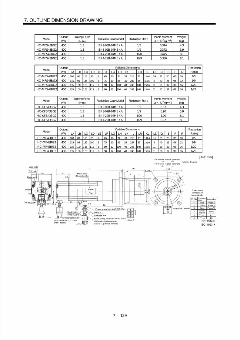
8/10/2019 Servo Motor - Instruction Manual SH(NA)-3181-D (03.00)
http://slidepdf.com/reader/full/servo-motor-instruction-manual-shna-3181-d-0300 208/368
7 - 129
7. OUTLINE DIMENSION DRAWING
ModelOutput
(W)Braking Force
(N•m)Reduction Gear Model Reduction Ratio
Inertia MomentJ( 10 -4kg•m 2)
Weight(kg)
HC-MFS43BG2 400 1.3 BK2-05B-04MEKA 1/5 0.344 4.3HC-MFS43BG2 400 1.3 BK3-09B-04MEKA 1/9 0.372 5.9HC-MFS43BG2 400 1.3 BK4-20B-04MEKA 1/20 0.475 8.1
HC-MFS43BG2 400 1.3 BK4-29B-04MEKA 1/29 0.386 8.1
Variable DimensionsModel
Output(W) LA LB LC LD LE LF LG LH LK L LR KL LZ Q S P R
(ReductionRatio)
HC-MFS43BG2 400 100 80 115 85 6 65 10 74 33 216 75 131.6 6.6 35 20 M5 10 1/5HC-MFS43BG2 400 115 95 135 100 8 75 10 85 35 237 85 152.6 9 40 25 M6 12 1/9HC-MFS43BG2 400 135 110 155 115 8 90 12 100 40 243 100 158.6 11 50 32 M8 16 1/20HC-MFS43BG2 400 135 110 155 115 8 90 12 100 40 243 100 158.6 11 50 32 M8 16 1/29
ModelOutput
(W)Braking Force
(N•m)Reduction Gear Model Reduction Ratio
Inertia MomentJ( 10 -4kg•m 2)
Weight(kg)
HC-KFS43BG2 400 1.3 BK2-05B-04MEKA 1/5 0.87 4.3HC-KFS43BG2 400 1.3 BK3-09B-04MEKA 1/9 0.90 5.9HC-KFS43BG2 400 1.3 BK4-20B-04MEKA 1/20 1.00 8.1
HC-KFS43BG2 400 1.3 BK4-29B-04MEKA 1/29 0.92 8.1
Variable DimensionsModel
Output(W) LA LB LC LD LE LF LG LH LK L LR KL LZ Q S P R
(ReductionRatio)
HC-MF43BG2 400 100 80 115 85 6 65 10 74 33 216 75 131.6 6.6 35 20 M5 10 1/5HC-MF43BG2 400 115 95 135 100 8 75 10 85 35 237 85 152.6 9 40 25 M6 12 1/9HC-MF43BG2 400 135 110 155 115 8 90 12 100 40 243 100 158.6 11 50 32 M8 16 1/20HC-MF43BG2 400 135 110 155 115 8 90 12 100 40 243 100 158.6 11 50 32 M8 16 1/29
Power supplyconnector pinconnection list
123
4
Pin No.
RedWhiteBlackGreen/yellow
Application
Phase UPhase VPhase W
Earth
Lead wirecolor
BC11914(BC11923)
56
B1B2
[Unit: mm]
Logo plate
Motor plate
With connector 1-172169-9(AMP maker)
Encoder cable 0.3m
Motor plate(Opposite side)
LGLRL
41LE
LK Q
689.9
KL25.2
Top 3 8 . 4
Bottom
Top
TUV plate
Caution plate
TopBottom
For reverse rotation command
For forward rotation commandRotation direction
LD
L A
P threads, depthR
S h 6
L F L B h 7
201 4
2 5
Arrow A
4 - LZ
Top
Bottom L C
4 2 . 8
4 5 °
5557-06R-210 (Receptacle)5556PBTL (Female terminal)
Power supply connector (Molex make)
Protective tube
Power supply lead 4-AWG19 0.3m
L H
2.7
Arrow A
62
Bottom
Break cable
VCTF 2-0.3 0 .3m2
Insulock
3 6
10.6

8/10/2019 Servo Motor - Instruction Manual SH(NA)-3181-D (03.00)
http://slidepdf.com/reader/full/servo-motor-instruction-manual-shna-3181-d-0300 209/368
7 - 130
7. OUTLINE DIMENSION DRAWING
ModelOutput
(W)Braking Force
(N•m)Reduction Gear
ModelReduction Ratio
Inertia MomentJ( 10 -4kg•m 2)
Weight(kg)
HC-MFS73BG2 750 2.4 BK3-05B-08MEKA 1/5 1.098 7.3HC-MFS73BG2 750 2.4 BK4-09B-08MEKA 1/9 1.105 9.6HC-MFS73BG2 750 2.4 BK5-20B-08MEKA 1/20 1.141 13.0
HC-MFS73BG2 750 2.4 BK5-29B-08MEKA 1/29 1.035 13.0
Variable DimensionsModel
Output(W) LA LB LC LD LE LF LG LH LK L LR KL LZ Q S P R
(ReductionRatio)
HC-MFS73BG2 750 115 95 135 100 8 75 10 85 35 247.5 85 156.7 9 40 25 M6 12 1/5HC-MFS73BG2 750 135 110 155 115 8 90 12 100 40 283.5 100 192.7 11 50 32 M8 16 1/9HC-MFS73BG2 750 150 125 175 130 10 105 15 115 43 283.5 115 192.7 14 60 40 M10 20 1/20HC-MFS73BG2 750 150 125 175 130 10 105 15 115 43 283.5 115 192.7 14 60 40 M10 20 1/29
Power supplyconnector pinconnection list
123
4
Pin No.
RedWhiteBlackGreen/yellow
Application
Phase UPhase VPhase W
Earth
Lead wirecolor
BC11915
56
B1B2
[Unit: mm]
Logo plate
Motor plate
With connector 1-172169-9(AMP maker)
Encoder cable 0.3m
Motor plate(Opposite side)
LG
LRL
39
LE
LK Q
729.9 KL
25.2
Top 4 8 . 7
Bottom
Top
TUV plate
Caution plate
Top
For reverse rotation command
For forward rotation commandRotation direction
LD
L A
P threads, depthR
S h 6
L F L B h 7
201 4
2 5
Arrow A
4 - LZ
TopBottom
L C
5 8 . 1
4 5 °
5557-06R-210 (Receptacle)5556PBTL (Female terminal)
Power supply connector (Molex make)Protective tube
Power supply lead 4-AWG19 0.3m
L H
2.7
Arrow A
82
Bottom
Break cableVCTF 2-0.3 0.3m2
Insulock
3 6
Bottom

8/10/2019 Servo Motor - Instruction Manual SH(NA)-3181-D (03.00)
http://slidepdf.com/reader/full/servo-motor-instruction-manual-shna-3181-d-0300 210/368
7 - 131
7. OUTLINE DIMENSION DRAWING
7.1.11 HC-UFS 3000r/min Series
(1) Standard (without electromagnetic brake)
ModelOutput
(W)Inertia MomentJ( 10 -4kg•m 2)
Weight(kg)
HC-UFS13 100 0.066 0.8
Power supplyconnector pinconnection list
123
4
Pin No.
RedWhiteBlackGreen/yellow
Application
Phase UPhase VPhase W
Earth
Lead wirecolor
[Unit: mm]
BC11876
20
5557-04R-210 (Receptacle)5556PBTL (Female terminal)
With connector 1-172169-9(AMP maker)
Arrow A
4 5 °
4 2 . 8
Bottom
Top
Protective tube
Motor plate(Opposite side)
5 0 h 7
60
8 h 6
Logo plate
Power supply connector (Molex make)Encoder cable 0.3m
Motor plate
Caution plate
Bottom
TopBottom
Top
25
3
5
70
9.933
26.9
4 0
4- 5.8
Power supply lead 4-AWG19 0.3m
TUV plate
Arrow A
Top
Bottom
1
2 4
3
6
4 0
Oil sealSC10207
R 5
Variable DimensionsModel
Output(W) L KL
Inertia MomentJ( 10 -4kg•m 2)
Weight(kg)
HC-UFS23 200 77 43.8 0.241 1.5HC-UFS43 400 92 58.8 0.365 1.7
Power supplyconnector pinconnection list
123
4
Pin No.
RedWhiteBlackGreen/yellow
Application
Phase UPhase VPhase W
Earth
Lead wirecolor
[Unit: mm]
BC11877
20
5557-04R-210 (Receptacle)5556PBTL (Female terminal)
With connector 1-172169-9(AMP maker)
Arrow A
4 5 °
5 5
Bottom
Top
Protective tube
Motor plate(Opposite side)
7 0 h 7
9 0
80
1 4 h 6
Logo plate
Power supply connector (Molex make)Encoder cable 0.3m
Motor plate
Caution plate
Bottom
Top
Bottom
Top
KL
30
38
L
9.926.9
5 0
4- 6.6
Power supply lead 4-AWG19 0.3m
TUV plate
Arrow A
Top
Bottom
1
2 4
3
6.5
5 6
Oil sealSC15307
R 7

8/10/2019 Servo Motor - Instruction Manual SH(NA)-3181-D (03.00)
http://slidepdf.com/reader/full/servo-motor-instruction-manual-shna-3181-d-0300 211/368
7 - 132
7. OUTLINE DIMENSION DRAWING
ModelOutput
(W)Inertia MomentJ( 10 -4kg•m 2)
Weight(kg)
HC-UFS73 750 5.9 5.0
Power supplyconnector pinconnection list
123
4
Pin No.
RedWhiteBlack
Green/yellow
Application
Phase UPhase VPhase W
Earth
Lead wirecolor
[Unit: mm]
BC11878
20
5557-04R-210 (Receptacle)5556PBTL (Female terminal)
With connector 1-172169-9 (AMP maker)
Arrow A
4 5 °
7 6
Bottom
Top
Protective tube
Motor plate
(Opposite side)
1 1 h 7 1 6
5
123
1 9 h 6
Logo plate
Power supply connector (Molex make)
Encoder cable 0.3m
Motor plate
Caution plate
Bottom
Top
BottomTop
40
3.5
10
85
55.5
26.9
7 2
4- 9
Power supply lead 4-AWG19 0.3m
TUV plate
Arrow A
TopBottom
1
2 4
3
6
8 0
Oil sealSC20357
32.5
1 4 5
70
(2) With electromagnetic brake
ModelOutput
(W)Braking Force
(N•m)Inertia MomentJ( 10 -4kg•m 2)
Weight(kg)
HC-UFS13B 100 0.32 0.074 1.2
Power supplyconnector pinconnection list
123
4
Pin No.
RedWhiteBlackGreen/yellow
Application
Phase UPhase VPhase W
Earth
Lead wirecolor
[Unit: mm]
BC11884
20
5557-06R-210 (Receptacle)5556PBTL (Female terminal)
With connector 1-172169-9 (AMP maker)
Arrow A
4 5 °
4 2 . 8
Bottom
Top
Protective tube
Motor plate(Opposite side)
5 0 h 7
60
8 h 6
Logo plate
Power supply connector (Molex make)
Encoder cable 0.3m
Motor plate
Caution plate
Bottom
TopBottom
Top
46.7
25
35
100
9.9
26.9
4 0
4- 5.8
Power supply lead 4-AWG19 0.3m
TUV plate
Arrow A
Top
1
2 5
4
6
4 0
Oil sealSC10207
33
7 0 Bottom
Insulock
Break cable
VCTF 2-0.3 0.3m2 3 6
R 5
56
B1B2

8/10/2019 Servo Motor - Instruction Manual SH(NA)-3181-D (03.00)
http://slidepdf.com/reader/full/servo-motor-instruction-manual-shna-3181-d-0300 212/368
7 - 133
7. OUTLINE DIMENSION DRAWING
Variable DimensionsModel
Output(W) L KL
Braking Force(N•m)
Inertia MomentJ( 10 -4kg•m 2)
Weight(kg)
HC-UFS23B 200 111 43.8 1.3 0.323 2.2HC-UFS43B 400 126 58.8 1.3 0.477 2.4
Power supplyconnector pinconnection list
123
4
Pin No.
RedWhiteBlackGreen/yellow
Application
Phase UPhase VPhase W
Earth
Lead wirecolor
[Unit: mm]
BC11885
20
5557-06R-210 (Receptacle)5556PBTL (Female terminal)
With connector 1-172169-9 (AMP maker)
Arrow A
4 5 °
5 5
Bottom
Top
Protective tube
Motor plate(Opposite side)
7 0 h 7
80
1 4 h 6
Logo plate
Power supply connector (Molex make)
Encoder cable 0.3m
Motor plate
Caution plate
Bottom
Top
Bottom
Top
47.2
30
38
L
9.926.9
5 0
4- 6.6
Power supply lead 4-AWG19 0.3m
TUV plate
Arrow A
Top
12 5
4
6.5
5 6
Oil sealSC15307KL
9 0 Bottom
Insulock
Break cable
VCTF 2-0.3 0.3m23 6
R 7
56
B1B2
ModelOutput
(W)Braking Force
(N•m)Inertia MomentJ( 10 -4kg•m 2)
Weight(kg)
HC-UFS73B 750 2.4 6.1 6.2
Power supplyconnector pinconnection list
123
4
Pin No.
RedWhiteBlackGreen/yellow
Application
Phase UPhase VPhase W
Earth
Lead wirecolor
[Unit: mm]
BC11886
20
5557-06R-210 (Receptacle)5556PBTL (Female terminal)
With connector 1-172169-9 (AMP maker)
Arrow A
4 5 °
7 6
Bottom
Top
Protective tube
Motor plate(Opposite side)
1 0 h 7
123
1 9 h 6
Logo plate
Power supply connector (Molex make)
Encoder cable 0.3m
Motor plate
Caution plate
BottomTop
Bottom
Top
40
3.5
10
111
76
26.9
7 2
4- 9
Power supply lead 4-AWG19 0.3m
TUV plate
Arrow A
Top
1
2 5
4
6
8 0
Oil sealSC20357
1 4 5
Bottom
Insulock
Break cable
VCTF 2-0.3 0.3m2
3 6 56
B1B2
96
55.5
32.5
1 6 5

8/10/2019 Servo Motor - Instruction Manual SH(NA)-3181-D (03.00)
http://slidepdf.com/reader/full/servo-motor-instruction-manual-shna-3181-d-0300 213/368
7 - 134
7. OUTLINE DIMENTION DRAWING
7.2 Servo Motors (in inches)
7.2.1 HC-MF•HC-KF Series
(1) Standard (without electromagnetic brake, without reduction gear)Variable Dimensions(in)
ModelOutput
(W) L KLInertia Moment
WK2(oz•in 2)Weight
(lb)
HC-MF053 50 3.21 1.16 0.10 0.9HC-MF13 100 3.80 0.18 0.16 1.2HC-KF053 50 3.21 0.12 0.29 0.9HC-KF13 100 3.80 1.75 0.46 1.2
Power supply lead 4-AWG19 11.8in
(With end-insulated roundcrimping terminal 1.25-4)
Red: Phase UWhite: Phase VBlack: Phase WGreen/yellow: Earth
Top
Bottom
Moter plate(Opposite side)
Encoder cable 11.8in
With connctor 1-172169-9(AMP make)
Moter plate
0.984
0.0980.197
0.787
4 5 °
L
Top
Bottom
1 . 4 0 6
KL0.390
1.575
2- 0.177
0 . 3 1 5
1 . 1 8 1
BC12031(BC12034 )
Caution plate
Top
Bottom
1.5941.654
0.268
0.992
1 . 1 3 0
1 .8 1 1
[Unit: in]
Variable Dimensions(in)Model
Output(W) L KL
Inertia MomentWK2(oz •in 2)
Weight(lb)
HC-MF23 200 3.92 1.93 0.48 2.2HC-MF43 400 4.90 0.06 0.78 3.2HC-MF23 200 3.92 1.93 2.30 2.2HC-MF43 400 4.90 0.06 3.66 3.2
Encoder cable 11.8inWith connector 1-172169-9(AMP make)
Power supply lead 4-AWG19 11.8in
Red: Phase UWhite: Phase VBlack: Phase WGreen/yellow: Earth
4 5 °Motor plate(Opposite side)
1.181
Motor plate
Bottom
Top Bottom
Top
L
Bottom
Top
(With end-insulated round crimping terminal 1.25-4)
0.787
1 . 6 8 5
0.390KL
2.362
0 . 5 5 1
4- 0.228
1 . 9 6 9
BC12032
0.276 0.118
Caution plate
(BC12035 )
1.6142.441 0.106
0.4170.992
1 . 5 1 2
2 .7 5 6
[Unit: in]

8/10/2019 Servo Motor - Instruction Manual SH(NA)-3181-D (03.00)
http://slidepdf.com/reader/full/servo-motor-instruction-manual-shna-3181-d-0300 214/368
7 - 135
7. OUTLINE DIMENSION DRAWING
ModelOutput
(W)Inertia Moment
WK2(oz •in 2)Weight
(lb)
HC-MF73 750 3.28 6.6
Encoder cable 11.8inWith connector 1-172169-9(AMP make)
Power supply lead 4-AWG19 11.8in
Red: Phase UWhite: Phase VBlack: Phase WGreen/yellow: Earth
4 5 °Motor plate(Opposite side)
5.591
0.315 0.118
1.575
2 . 2 8 7
0.787
3.413
(With end-insulated round crimping terminal 1.25-4)
Top
Bottom
TopBottom
Top
0.390
0 . 7 4 8Motor plate
2 . 7 5 6Bottom
3.1504- 0.260
3 .5 4 3
BC12033
Caution plate
1.535
3.228
0.106
0.992
1 . 9 1 7
0.433
[Unit: in]
(2) With electromagnetic brakeVariable Dimensions (in)
ModelOutput
(W) L KL
Braking Force(oz•in)
Inertia MomentWK2(oz•in 2)
Weight(lb)
HC-MF053B 50 4.31 1.16 45.32 0.12 1.7HC-MF13B 100 4.90 1.75 45.32 0.18 2.0HC-KF053B 50 4.31 1.16 45.32 0.31 1.7
HC-KF13B 100 4.90 1.75 45.32 0.48 2.0
Motor plate(Opposite side)
Top
Bottom
Power supply lead 4-AWG19 11.8in
Red: Phase UWhite: Phase VBlack: Phase WGreen/yellow: Earth
KL0.390
Brake lead2-0.3 11.8in(With end-insulated roundcrimping terminal 1.25-4)
1 . 4 0 6
0.787
0.197 0.098
0.984L
2.579
Motor plate
Top
Bottom
Top
Bottom
2Encoder cable 11.8inWith connector 1-172169-9(AMP make)
Caution plate
(With end-insulated round c rimping terminal 1.25-4)
2- 0.177
1.575
1 . 1 8 1
0 . 3 1 5
(BC12039 )BC12036
4 5 °
1.5941.654
0.268
0.992
1 . 1 3 0
1 .8 1 1
[Unit: in]

8/10/2019 Servo Motor - Instruction Manual SH(NA)-3181-D (03.00)
http://slidepdf.com/reader/full/servo-motor-instruction-manual-shna-3181-d-0300 215/368
7 - 136
7. OUTLINE DIMENSION DRAWING
Variable Dimensions (in)Model
Output(W) L KL
Braking Force(oz•in)
Inertia MomentWK2(oz•in 2)
Weight(lb)
HC-MF23B 200 5.18 1.93 184 0.74 3.5HC-MF43B 400 6.16 2.84 184 1.04 4.6HC-KF23B 200 5.18 1.93 184 2.57 3.5
HC-KF43B 400 6.16 2.84 184 3.94 4.6
Brake lead
2-0.3 2 11.8in(With end-insulated roundcrimping terminal 1.25-4)
Power supply lead 4-AWG19 11.8in
Red: Phase UWhite: Phase VBlack: Phase WGreen/yellow: Earth
Encoder cable 11.8inWith connector 1-172169-9(AMP make)
2.677 0.390KL
L 1.1810.276 0.118Motor plate
(Opposite side)
Top
Bottom 1 . 9 6 9
2.362
4 5
1 . 6 8 5
4 - 0 .22 8
TopBottom
Bottom
BC12037
0.787
0 . 5 5 1
(With end-insulated round c rimping terminal 1.25-4)
Motor plate
Caution plate
(BC12039 )
1.6142.441 0.106
0.417
0.992
1 . 5 1 2
2 .7 5 6
[Unit: in]
Top
ModelOutput
(W)Braking Force
(oz•in)Inertia Moment
KW2(oz•in 2)Weight
(lb)
HC-MF73B 750 340 3.96 8.8
Encoder cable 11.8inWith connector 1-172169-9(AMP make)
Brake lead2-0.3 11.8in(With end-insulated roundcrimping terminal 1.25-4)
2
Power supply lead 4-AWG19 11.8in
Red: Phase UWhite: Phase VBlack: Phase WGreen/yellow: Earth
Motor plate(Opposite side)
Motor plate
Top
Bottom
Top
Bottom
6.988
2.835
3.4130.390
(With end-insulated round crimping terminal 1.25-4)
BC12038
1.575
0.1180.315
Caution plate
Top
Bottom
3.150
0.768
2 . 2 8 7
0.787
0 . 7 4 8
2 . 7 5 6
4 5 °4- 0.260
1.535
3.228
0.106
0.992
1 . 9 1 7
0.433
3 .5 4 3
[Unit: in]

8/10/2019 Servo Motor - Instruction Manual SH(NA)-3181-D (03.00)
http://slidepdf.com/reader/full/servo-motor-instruction-manual-shna-3181-d-0300 216/368
7 - 137
7. OUTLINE DIMENSION DRAWING
(3) With reduction gear for general industrial machine(a) Without electromagnetic brake
Variable Dimensions (in)Model
Output(W) L KL
ReductionGear Model
Reduction Ratio(Actual Reduction Ratio)
Inertia MomentWK2(oz•in 2)
BacklashWeight
(lb)
HC-MF053G1 50 4.96 2.91 K6505 1/5(9/44) 0.30 60min. max. 3.1HC-MF053G1 50 5.669 3.62 K6512 1/12(49/576) 0.42 60min. max. 4.0HC-MF053G1 50 5.669 3.62 K6520 1/20(25/484) 0.32 60min. max. 4.0HC-KF053G1 50 4.96 2.91 K6505 1/5(9/44) 0.49 60min. max. 3.1HC-KF053G1 50 5.669 3.62 K6512 1/12(49/576) 0.61 60min. max. 4.0HC-KF053G1 50 5.669 3.62 K6520 1/20(25/484) 0.51 60min. max. 4.0
"Rotation direction"
For forward rotation command
For reverse rotation command
M4 threads,depth 0.315
Encoder cable 11.8inWith connector 1-172169-9(AMP make)
Power supply lead 4-AWG19 11.8in (With end-insulated round crimping terminal 1.25-4)
Red: Phase UWhite: Phase VBlack: Phase WGreen/yellow: Earth
4 5 °
Motor plate
Motor plate(Opposite side)
Caution plate
L
0.390KL
0.315 0.256
2.382
0.984
4- 0.276
1 . 4 0 6
0.787
0 . 6 3 0
1 . 8 9 0
2 . 3 6 2
2.559
BC12066(BC12086 )
Bottom
Top Bottom
Top
1.102
Bottom
Top
1.5941.654
0.268
0.992
1 . 1 3 0
2. 9 5 3
3 . 4 6 5
[Unit: in]
Variable Dimensions (in)Model
Output(W) L KL
ReductionGear Model
Reduction Ratio(Actual Reduction Ratio)
Inertia MomentWK2(oz•in 2)
BacklashWeight
(lb)
HC-MF13G1 100 5.551 3.5 K6505 1/5(9/44) 0.36 60min. max. 3.3HC-MF13G1 100 6.26 4.21 K6512 1/12(49/576) 0.48 60min. max. 4.2HC-MF13G1 100 6.26 4.21 K6520 1/20(25/484) 0.38 60min. max. 4.2HC-KF13G1 100 5.551 3.5 K6505 1/5(9/44) 0.66 60min. max. 3.3HC-KF13G1 100 6.26 4.21 K6512 1/12(49/576) 0.78 60min. max. 4.2HC-KF13G1 100 6.26 4.21 K6520 1/20(25/484) 0.68 60min. max. 4.2
"Rotation direction"For forward rotation command
For reverse rotation command
Encoder cable 11.8inWith connector 1-172169-9(AMP make)
Power supply lead 4-AWG19 11.8in (With end-insulated round c rimping terminal 1.25-4)
Red: Phase UWhite: Phase VBlack: Phase WGreen/yellow: Earth
4 5 °
Motor plate
Motor plate(Opposite side)
Caution plate0.390
KL
L
Bottom
Top Bottom
Top
Top
Bottom
BC12067(BC12087 )
1.5941.654
0.268
0.992
1 . 1 3 0
0.315 0.256
2.382
0.984
0 . 6 3 0
1 . 8 9 0
2 . 3 6 2
1.102
M4 threads,
depth 0.315
4- 0.276
1 . 4 0 6
0.787
2.559
2. 9 5 33 .4 6 5
[Unit: in]

8/10/2019 Servo Motor - Instruction Manual SH(NA)-3181-D (03.00)
http://slidepdf.com/reader/full/servo-motor-instruction-manual-shna-3181-d-0300 217/368
7 - 138
7. OUTLINE DIMENSION DRAWING
Variable Dimensions (in)Model
Output(W) L KL
ReductionGear Model
Reduction Ratio(Actual Reduction Ratio)
Inertia MomentWK2(oz•in 2)
Weight(lb)
HC-MF23G1 200 6.02 4.04 K9005 1/5(19/96) 1.36 7.3HC-MF23G1 200 6.81 4.83 K9012 1/12(25/288) 1.60 8.6HC-MF23G1 200 6.81 4.83 K9020 1/20(253/5000) 1.45 8.6
HC-KF23G1 200 6.02 4.04 K9005 1/5(19/96) 3.17 7.3HC-KF23G1 200 6.81 4.83 K9012 1/12(25/288) 3.44 8.6HC-KF23G1 200 6.81 4.83 K9020 1/20(253/5000) 3.28 8.6
L
Top
Bottom
M6 threads,depth0.472
"Rotation direction"For forward rotation command
For reverse rotation command
Encoder cable 11.8inWith connector 1-172169-9(AMP make)
Power supply lead 4-AWG19 11.8i n (With end-insulated round crimping terminal 1.25-4)
Red: Phase UWhite: Phase VBlack: Phase WGreen/yellow: Earth
4 5 °
Top
Bottom
Motor plate(Opposite side)
Motor plate
Caution plate
KL
4- 0.354
BC12068(BC12088 )
0.787
3.543
Top
Bottom
1.6142.441
0.106
0.4170.992
1 . 5 1 2
1 . 6 8 5
0.390
0.394 0.3152.913
1.378
0 . 9 8 4
2 . 8 7 4
3 . 2 2 8
1.181
3. 9 3 7
4. 4 8 8
[Unit: in]
Variable Dimensions (in)Model
Output(W) L KL
ReductionGear Model
Reduction Ratio(Actual Reduction Ratio)
Inertia MomentWK2(oz•in 2)
Weight(lb)
HC-MF43G1 400 7.01 4.95 K9005 1/5(19/96) 1.62 8.4HC-MF43G1 400 7.80 5.73 K9012 1/12(25/288) 1.85 9.7HC-KF43G1 400 7.01 4.95 K9005 1/5(19/96) 4.48 8.4HC-KF43G1 400 7.80 5.73 K9012 1/12(25/288) 4.76 9.7
Motor plate
Top
Bottom
BC12069Encoder cable 11.8inWith connector 1-172169-9(AMP make)
Power supply lead 4-AWG19 11.8in
(With end-insulated round crimping terminal 1.25-4)Red: Phase UWhite: Phase VBlack: Phase WGreen/yellow: Earth
4 5 °
Top
Bottom
Top
Bottom
Motor plate(Opposite side)
Caution plate
"Rotation direction"
For forward rotation command
For reverse rotation command
KL
(BC12089 )
L
1.6142.441
0.106
0.4170.992
1 . 5 1 2
1 . 6 8 5
0.390
0.394 0.315
2.913
1.378
0 . 9 8 4
2 . 8 7 4
3 . 2 2 8
1.181
M6 threads,depth0.472
4- 0.354
0.787
3.543
3. 9 3 7
4. 4 8 8
[Unit: in]

8/10/2019 Servo Motor - Instruction Manual SH(NA)-3181-D (03.00)
http://slidepdf.com/reader/full/servo-motor-instruction-manual-shna-3181-d-0300 218/368
7 - 139
7. OUTLINE DIMENSION DRAWING
Reduction RatioModel
Output(W)
Reduction Gear Model Normal Reduction ratio Actual Reduction Ratio
Inertia MomentWK2(oz•in 2)
BacklashWeight
(lb)
HC-MF43G1 400 K10020 1/20 253/5000 3.57 60min. max. 12.13HC-MF73G1 750 K10005 1/5 1/5 5.58 60min. max. 13.67HC-MF73G1 750 K10012 1/12 525/6048 9.22 60min. max. 16.09
HC-MF73G1 750 K12020 1/20 625/12544 9.57 60min. max. 22.27
Variable Dimensions (in)Model
Output
(W) D LH LK LT H LA LB LC LD LE LF LG LM LN LP L LR KL LZ Q S P R
(Reduction
Ratio)
HC-MF43G1 400 2.362 1.50 1.61 0.42 1.69 4.53 3.74 5.20 3.94 0.39 2.87 0.39 0.512 0.63 3.39 7.933 3.54 5.87 0.35 1.97 1.26 M8 0.63 1/20
HC-MF73G1 750 3.15 1.89 1.54 0.43 2.29 4.53 3.74 5.20 3.94 0.39 2.87 0.39 0.512 0.63 3.39 8.15 3.54 5.97 0.35 1.97 1.26 M8 0.63 1/5
HC-MF73G1 750 3.15 1.89 1.54 0.43 2.29 4.53 3.74 5.20 3.94 0.39 2.87 0.39 0.512 0.63 3.39 9.016 3.54 6.84 0.35 1.97 1.26 M8 0.63 1/12
HC-MF73G1 750 3.15 1.89 1.54 0.43 2.29 5.51 4.53 6.38 4.72 0.47 3.54 0.59 0.512 0.787 4.09 9.528 4.17 7.35 0.55 2.36 1.57 M10 0.79 1/20
LD4- LZ
Top
Bottom
BC12070
P threads,depth R
L C
"Rotation direction"For forward rotation command
For reverse rotation command
Power supply lead 4-AWG19 11.8in (With end-insulated round crimping terminal 1.25-4)Encoder cable 11.8in
With connector 1-172169-9(AMP make)
Red: Phase UWhite: Phase VBlack: Phase WGreen/yellow: Earth
4 5 °
L H
0.992
D
TopBottom
Top
Bottom
Motor plate
(Opposite side)
Motor plate
LK
KL
LR
LT H 0.390
0.106
LG LE
LM LM Q
S h 6
L F L P L B h 7
0.787
L A
Caution plate
L
[Unit: in]
Reduction RatioModel
Output(W)
Reduction Gear Model Normal Reduction ratio Actual Reduction Ratio
Inertia MomentWK2(oz•in 2)
BacklashWeight
(lb)
HC-K F43G1 400 K 10020 1/20 253/5000 6.45 60min. max. 12.13
7.933
0.630
0.394
3.543
P threads,depth 0.630
1.969
"Rotation direction"For forward rotation command
For reverse rotation command
Power supply lead 4-AWG19 11.8in (With end-insulated round crimping terminal 1.25-4)
Encoder cable 11.8inWith connector 1-172169-9(AMP make)
Red: Phase UWhite: Phase VBlack: Phase WGreen/yellow: Earth
4 5 °
Motor plate(Opposite side)
Motor plate
Caution plate
Top
Bottom
Top
Bottom
5.870
3 . 7 4 0
3 . 3 8 6
2 . 8 7 4
1 . 2 6 0
4- 0.3543.937
Top
Bottom
BC12090
0.787
1.6142.441
0.106
0.4170.992
1 . 5 1 2
1 . 6 8 5
0.390
0.394
4 . 5 2 8
5. 1 9 7
[Unit: in]
0.512

8/10/2019 Servo Motor - Instruction Manual SH(NA)-3181-D (03.00)
http://slidepdf.com/reader/full/servo-motor-instruction-manual-shna-3181-d-0300 219/368
7 - 140
7. OUTLINE DIMENSION DRAWING
(b) With electromagnetic brakeVariable Dimensions (in)
ModelOutput
(W) L KLBraking Force
(oz•in)Reduction
Gear ModelReduction
RatioInertia Moment
WK2(oz•in 2)Backlash
Weight(lb)
HC-MF053BG1 50 6.06 2.91 45 K6505 1/5(9/44) 0.32 60min. max. 4.0HC-MF053BG1 50 6.77 3.62 45 K6512 1/12(49/576) 0.44 60min. max. 4.9HC-MF053BG1 50 6.77 3.62 45 K6520 1/20(25/484) 0.34 60min. max. 4.9HC-KF053BG1 50 6.02 2.91 45 K6505 1/5(9/44) 0.51 60min. max. 4.0HC-KF053BG1 50 6.77 3.62 45 K 6512 1/12(49/576) 0.63 60min. max. 4.9HC-KF053BG1 50 6.77 3.62 45 K 6520 1/20(25/484) 0.53 60min. max. 4.9
Motor plate(Opposite side)
0.984
0.315 0.256
Top
Bottom
1.102
2.382
"Rotation direction"For forward rotation command
For reverse rotation command
Encoder cable 11.8inWith connector 1-172169-9(AMP make)
Power supply lead 4-AWG19 11.8in
Red: Phase UWhite: Phase VBlack: Phase WGreen/yellow: Earth
4 5 °
Brake lead2-0.3 11.8in2
(With end-insulated round crimping terminal 1.25-4)
(With end-insulated round crimping terminal 1.25-4)
L
Caution plate
Motor plate
2.5790.390
KL
Top
Bottom Top
Bottom
1.5941.654
0.268
0.992
1 . 1 3 0
0 . 6 3 0
1 . 8 9 0
2 . 3 6 2
M4 threads,depth 0.315
4- 0.276
1 . 4 0 6
0.787
2.559
2. 9 5 3
3. 4 6 5
[Unit: in]
BC12071(BC12091 )
Variable Dimensions (in)Model
Output(W) L KL
Braking Force(oz•in)
ReductionGear Model
ReductionRatio
Inertia MomentWK2(oz•in 2)
BacklashWeight
(lb)
HC-MF13BG1 100 6.65 3.43 45 K6505 1/5(9/44) 0.38 60min. max. 4.2HC-MF13BG1 100 7.36 4.21 45 K6512 1/12(49/576) 0.50 60min. max. 5.1HC-MF13BG1 100 7.36 4.21 45 K6520 1/20(25/484) 0.40 60min. max. 5.1HC-KF13BG1 100 6.65 3.43 45 K6505 1/5(9/44) 0.68 60min. max. 4.2HC-KF13BG1 100 7.36 4.21 45 K6512 1/12(49/576) 0.80 60min. max. 5.1HC-KF13BG1 100 7.36 4.21 45 K6520 1/20(25/484) 0.7 60min. max. 5.1
Motor plate(Opposite side)
L
Top
Bottom
"Rotation direction"For forward rotation command
For reverse rotation command
Encoder cable 11.8inWith connector 1-172169-9(AMP make)
Brake lead2-0.3 11.8in2
Power supply lead 4-AWG19 11.8in
Red: Phase UWhite: Phase VBlack: Phase WGreen/yellow: Earth
4 5 °
(With end-insulated round crimping terminal 1.25-4)
(With end-insulated round crimpingterminal 1.25-4)
Motor plate
Caution plate
BC12072(BC12092 )
Top
Bottom
Top
Bottom
0.3902.579 KL
1.5941.654
0.268
0.992
1 . 1 3 0
0.315 0.256
2.382
0.984
0 . 6 3 0
1 . 8 9 0
2 . 3 6 2
1.102
M4 threads, depth 0.315
4- 0.276
1 . 4 0 6
0.787
2.559
2. 9 5 33 .4 6 5
[Unit: in]

8/10/2019 Servo Motor - Instruction Manual SH(NA)-3181-D (03.00)
http://slidepdf.com/reader/full/servo-motor-instruction-manual-shna-3181-d-0300 220/368
7 - 141
7. OUTLINE DIMENSION DRAWING
Variable Dimensions (in)Model
Output(W) L KL
ReductionGear Model
Reduction Ratio(Actual Reduction Ratio)
Inertia MomentWK2(oz•in 2)
Weight(lb)
HC-MF23BG1 200 6.65 4.04 K9005 1/5(19/96) 1.58 8.6HC-MF23BG1 200 7.36 4.23 K9012 1/12(25/288) 1.82 9.9HC-MF23BG1 200 7.36 4.23 K9020 1/20(253/5000) 1.67 9.9
HC-KF23BG1 200 6.65 4.04 K9005 1/5(19/96) 3.44 8.6HC-KF23BG1 200 7.36 4.23 K9012 1/12(25/288) 3.72 9.9HC-KF23BG1 200 7.36 4.23 K9020 1/20(253/5000) 3.55 9.9
Motor plate(Opposite side)
L
Top
Bottom
Encoder cable 11.8inWith connector 1-172169-9(AMP make)
Brake lead 2-0.3 11.8in(With end-insulated roundcrimping terminal 1.25-4)
2 Power supply lead 4-AWG19 11.8in (With end-insulated round crimping terminal 1.25-4)
Red: Phase UWhite: Phase VBlack: Phase WGreen/yellow: Earth
BC12073(BC120793 )
Top
Bottom
Top
Bottom
Motor plate
Caution plate 0.390KL
"Rotation direction"For forward rotation command
For reverse rotation command
4 5 °
2.677
1.6142.441
0.106
0.4170.992
1 . 5 1 2
1 . 6 8 5
0.394 0.3152.913
1.378
0 . 9 8 4
2 . 8 7 4
3 . 2 2 8
1.181
M6 threads, depth 0.472
4- 0.354
0.787
3.543
3. 9 3 7
4 .4 8 8
[Unit: in]
Variable Dimensions (in)Model
Output(W) L KL
Braking Force(oz•in)
ReductionGear Model
Reduction Ratio(Actual Reduction Ratio)
Inertia MomentWK2(oz•in 2)
Weight(lb)
HC-MF43BG1 400 8.27 4.95 184 K9005 1/5(19/96) 1.88 9.7HC-MF43BG1 400 9.06 5.73 184 K9012 1/12(25/288) 2.12 11.0HC-KF43BG1 400 8.27 4.95 184 K9005 1/5(19/96) 4.76 9.7HC-KF43BG1 400 9.06 5.73 184 K9012 1/12(25/288) 5.03 11.0
Motor plate(Opposite side)
Top
Bottom
"Rotation direction"For forward rotation command
For reverse rotation command
4 5 °
(BC12094 )BC12074
L
Power supply lead 4-AWG19 11.8in
(With end-insulated round crimping terminal 1.25-4)Red: Phase UWhite: Phase VBlack: Phase WGreen/yellow: Earth
Brake lead 2-0.3 11.8in(With end-insulated roundcrimping terminal 1.25-4)
2
Encoder cable 11.8inWith connector 1-172169-9(AMP make)
Motor plate
Caution plate
Top
Bottom
Top
Bottom
KL
2.677
1.6142.441
0.106
0.4170.992
1 . 5 1 2
0.394 0.3152.913
1.378
0 . 9 8 4
2 . 8 7 4
3 . 2 2 8
1.181
M6 threads,depth 0.472
4- 0.354
0.787
3.543
3. 9 3 7
4 .4 8 8
1 . 6 8 5
0.390
[Unit: in]

8/10/2019 Servo Motor - Instruction Manual SH(NA)-3181-D (03.00)
http://slidepdf.com/reader/full/servo-motor-instruction-manual-shna-3181-d-0300 221/368
7 - 142
7. OUTLINE DIMENSION DRAWING
Reduction RatioModel
Output(W)
Brake Force(oz•in)
ReductionGear Model Normal Reduction ratio Actual Reduction Ratio
Inertia MomentWK2(oz•in 2)
BacklashWeight
(lb)
HC-MF43BG1 400 184 K10020 1/20 253/5000 3.83 60min. max. 13.4HC-MF73BG1 750 340 K10005 1/5 1/5 6.26 60min. max. 15.9HC-MF73BG1 750 340 K10012 1/12 525/6048 9.90 60min. max. 18.3
HC-MF73BG1 750 340 K12020 1/20 625/12544 10.25 60min. max. 25.8
Variable Dimensions (in)Model
Output
(W) D LH LK LT LX H LA LB LC LD LE LF LG LM LN LP L LR KL LZ Q S P R
(Reduction
Ratio)
HC-MF43 BG1 400 2.44 1.51 1.64 0.14 2.68 1.69 4.53 3.74 5.20 3.94 0.39 2.87 0.39 0.512 0.63 3.39 9.19 3.54 5.87 0.35 1.97 1.26 M 8 0.63 1/20
HC-MF73 BG1 750 3.23 1.92 1.54 0.43 2.84 1.69 4.53 3.74 5.20 3.94 0.39 2.87 0.39 0.512 0.63 3.39 9.55 3.54 5.92 0.35 1.97 1.26 M8 0.63 1/5
HC-MF73 BG1 750 3.23 1.92 1.54 0.43 2.84 1.69 4.53 3.74 5.20 3.94 0.39 2.87 0.39 0.512 0.63 3.39 10.41 3.54 6.84 0.35 1.97 1.26 M8 0.63 1/12
HC-MF73 BG1 750 3.23 1.92 1.54 0.43 2.84 1.69 5.51 4.53 6.38 4.72 0.47 3.54 0.59 0.512 0.787 4.09 10.93 4.17 7.35 0.55 2.36 1.57 M10 0.79 1/20
Motor plate(Opposite side) LN
LELG
Top
Bottom
LM
LR
P threads,depth R
Q
S h 6
"Rotation direction"For forward rotation commandFor reverse rotation command
Brake lead 2-0.3 11.8in(With end-insulated roundcrimping terminal 1.25-4)
Encoder cable 11.8inWith connector 1-172169-9(AMP make)
Power supply lead 4-AWG19 11.8in (With end-insulated round crimping terminal 1.25-4)
2 Red: Phase UWhite: Phase VBlack: Phase WGreen/yellow: Earth
4 5 °
4- LZ LD
L C L A
0.787
L F L B h 7
L PTop
Bottom
Motor plate
Caution plate
D
LK0.106
L
0.992
L H
LTLX
H 0.390KL
Top
Bottom
BC12075
[Unit: in]
Reduction RatioModel
Output(W)
Brake Force(oz•in)
ReductionGear Model
NormalReduction ratio
ActualReduction Ratio
Inertia MomentWK2(oz•in 2)
BacklashWeight
(lb)
HC-KF43BG1 400 184 K10020 1/20 253/5000 6.73 60min. max. 13.4
Motor plate(Opposite side)
Top
Bottom
8 threads,depth 0.630
"Rotation direction"For forward rotation command
For reverse rotation command
(With end-insulated roundcrimping terminal 1.25-4)
Encoder cable 11.8inWith connector 1-172169-9(AMP make)
Power supply lead 4-AWG19 11.8in
(With end-insulated round crimping terminal 1.25-4)
Brake lead 2-0.3 11.8in2
Red: Phase UWhite: Phase VBlack: Phase WGreen/yellow: Earth
4- 0.354
0.787
Bottom
3.937
Motor plate
Top
Bottom
9.193
Caution plate 2.677 5.870
BC12095
4 5 ° 1.614
2.441
0.106
0.4170.992
1 . 5 1 2
1 . 6 8 5
0.390
0.3943.543
1.969
2 . 8 7 4
3 . 3 8 6
3 . 7 4 0
0.394
0.6300.512
4 . 5 2
8
[Unit: in]
5. 1 9 7
Top
1 . 2 6 0

8/10/2019 Servo Motor - Instruction Manual SH(NA)-3181-D (03.00)
http://slidepdf.com/reader/full/servo-motor-instruction-manual-shna-3181-d-0300 222/368
7 - 143
7. OUTLINE DIMENSION DRAWING
(4) With reduction gear for precision application(a) Without electromagnetic brake
Variable Dimensions (in)Model
Output(W) L KL
Reduction Gear Model
Reduction RatioInertia Moment
WK2(oz•in 2)Backlash
Weight(lb)
HC-MF053G2 50 5.12 3.07 BK1-05B-A5MEKA 1/5 0.36 3 min. max. 3.1HC-MF053G2 50 5.75 3.70 BK1-09B-A5MEKA 1/9 0.33 3 min. max. 3.7HC-MF053G2 50 5.75 3.70 BK1-20B-A5MEKA 1/20 0.38 3 min. max. 4.0HC-MF053G2 50 5.75 3.70 BK1-29B-A5MEKA 1/29 0.31 3 min. max. 4.0HC-KF053G2 50 5.12 3.07 BK1-05B-A5MEKA 1/5 0.55 3 min. max. 3.1HC-KF053G2 50 5.75 3.70 BK1-09B-A5MEKA 1/9 0.52 3 min. max. 3.7HC-KF053G2 50 5.75 3.70 BK1-20B-A5MEKA 1/20 0.57 3 min. max. 4.0HC-KF053G2 50 5.75 3.70 BK1-29B-A5MEKA 1/29 0.50 3 min. max. 4.0
Motor plate(Opposite side)
L
Top
Bottom
M4 threads,depth 0.315
"Rotation direction"For forward rotation command
For reverse rotation command
Power supply lead 4-AWG19 0.3m11.8in
(With end-insulated round crimping terminal 1.25-4)
Encoder cable 11.8inWith connector 172169-9(AMP make)
Red: Phase UWhite: Phase VBlack: Phase W
Green/yellow: Earth
Top
Bottom
2.756
4- 0.260 4 5 °
BC12076(BC12096 )
Motor plate
Caution plate
KL0.390
0.787
1.5941.654
0.268
0.992
1 . 1 3 0
0.3150.256
2.382
0.984
0 . 6 3 0
1 . 8 9 0
2 . 3 6 2
0.906
2 . 5 5 9
3. 1 5 0
3. 7 4 0
[Unit: in]
1 . 4
0 6
Top
Bottom

8/10/2019 Servo Motor - Instruction Manual SH(NA)-3181-D (03.00)
http://slidepdf.com/reader/full/servo-motor-instruction-manual-shna-3181-d-0300 223/368
7 - 144
7. OUTLINE DIMENSION DRAWING
ModelOutput
(W)Reduction Gear
ModelReduction Ratio
Inertia MomentWK2(oz•in 2)
BacklashWeight
(lb)
HC-MF13G2 100 BK1-05B-01MEK A 1/5 0.43 3 min. max. 3.3HC-MF13G2 100 BK1-09B-01MEK A 1/9 0.39 3 min. max. 4.0HC-MF13G2 100 B K2-20B-01MEK A 1/20 0.66 3 min. max. 6.6
HC-MF13G2 100 B K2-29B-01MEK A 1/29 0.52 3 min. max. 6.6
Variable DimensionsModel
Output(W) LA LB LC LD LE LF LG LH LK L LR KL LZ Q S P R
(ReductionRatio)
HC-MF13G2 100 3.15 2.56 3.74 2.76 0.24 1.89 0.31 2.362 0.906 5.71 2.17 3.66 0.26 0.98 0.63 M4 0.31 1/5HC-MF13G2 100 3.15 2.56 3.74 2.76 0.24 1.89 0.31 2.362 0.906 6.34 2.17 4.29 0.26 0.98 0.63 M4 0.31 1/9HC-MF13G2 100 3.94 3.15 4.53 3.35 0.24 2.559 0.39 2.913 1.299 6.57 2.95 4.53 0.26 1.38 0.79 M5 0.39 1/20HC-MF13G2 100 3.94 3.15 4.53 3.35 0.24 2.559 0.39 2.913 1.299 6.57 2.95 4.53 0.26 1.38 0.79 M5 0.39 1/29
ModelOutput
(W)Reduction Gear
ModelReduction Ratio
Inertia MomentWK2(oz•in 2)
BacklashWeight
(lb)
HC-KF13G2 100 BK1-05B-01MEK A 1/5 0.72 3 min. max. 3.3HC-KF13G2 100 BK1-09B-01MEK A 1/9 0.69 3 min. max. 4.0HC-K F13G2 100 BK 2-20B-01MEK A 1/20 0.96 3 min. max. 6.6HC-K F13G2 100 BK 2-29B-01MEK A 1/29 0.82 3 min. max. 6.6
Variable DimensionsModel
Output(W) LA LB LC LD LE LF LG LH LK L LR KL LZ Q S P R
(ReductionRatio)
HC-KF13G2 100 3.15 2.56 3.74 2.76 0.24 1.89 0.31 2.362 0.906 5.71 2.17 3.66 0.26 0.98 0.63 M4 0.31 1/5HC-KF13G2 100 3.15 2.56 3.74 2.76 0.24 1.89 0.31 2.362 0.906 6.34 2.17 4.29 0.26 0.98 0.63 M4 0.31 1/9HC-KF13G2 100 3.94 3.15 4.53 3.35 0.24 2.559 0.39 2.913 1.299 6.57 2.95 4.53 0.26 1.38 0.79 M5 0.39 1/20HC-KF13G2 100 3.94 3.15 4.53 3.35 0.24 2.559 0.39 2.913 1.299 6.57 2.95 4.53 0.26 1.38 0.79 M5 0.39 1/29
Motor plate(Opposite side)
0.390
LELG
L F L H
LD4- LZ
Top
Bottom
L B h 7
LK
P threads, depth R
Q
S h 6
"Rotation direction"
For forward rotation command
For reverse rotation command
Encoder cable 11.8inWith connector 1-172169-9(AMP make)
Power supply lead 4-AWG19 118in (With end-insulated round crimping terminal 1.25-4)
LR
Red: Phase UWhite: Phase VBlack: Phase W
Green/yellow: Earth
4 5 °
Motor plate
Caution plate
KL
0.787
L A
L C
Top
Bottom
Top
Bottom
L
BC12077(BC12097 )
1 . 4 0 6
1.5941.654
0.268
0.992
1 . 1 3 0
[Unit: in]
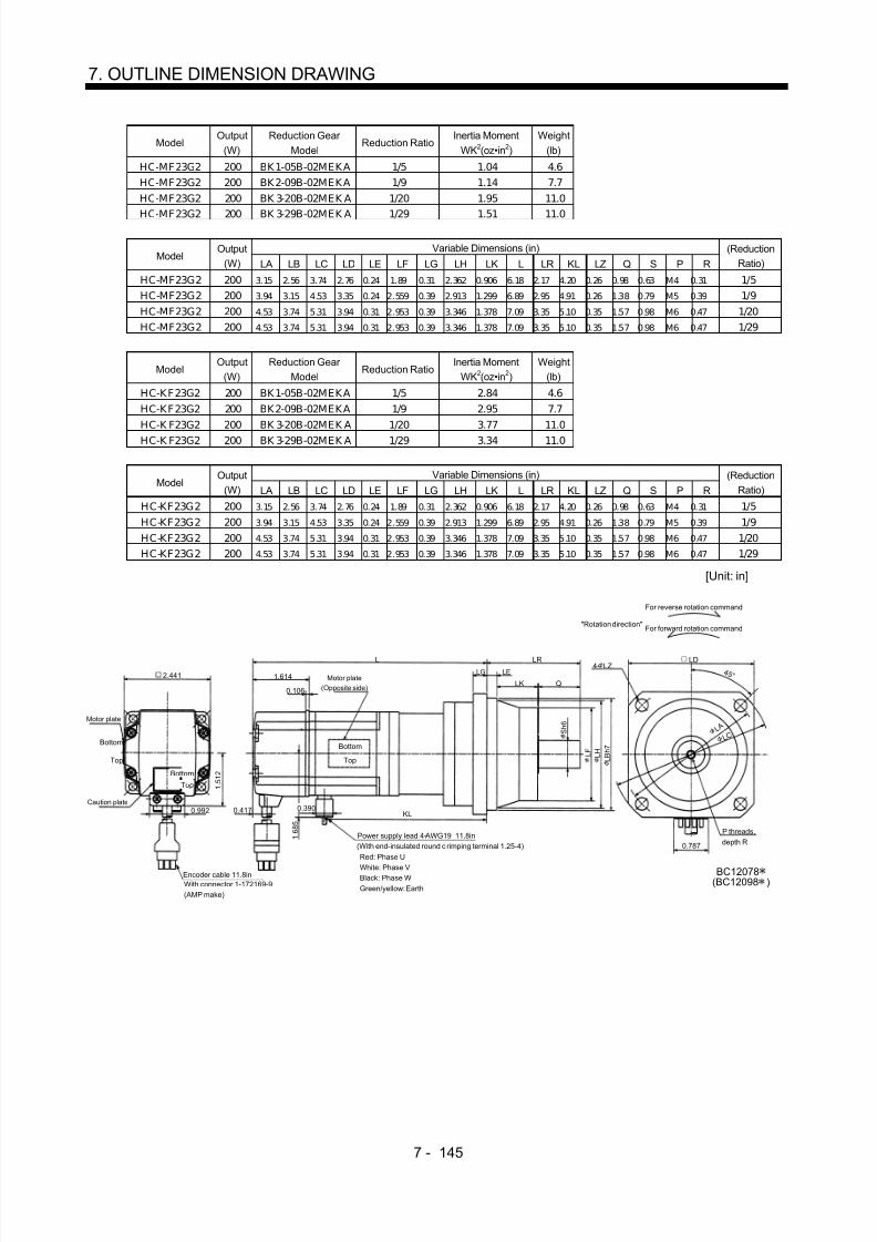
8/10/2019 Servo Motor - Instruction Manual SH(NA)-3181-D (03.00)
http://slidepdf.com/reader/full/servo-motor-instruction-manual-shna-3181-d-0300 224/368
7 - 145
7. OUTLINE DIMENSION DRAWING
ModelOutput
(W)Reduction Gear
ModelReduction Ratio
Inertia MomentWK2(oz•in 2)
Weight(lb)
HC-MF23G2 200 BK1-05B-02MEKA 1/5 1.04 4.6HC-MF23G2 200 BK2-09B-02MEKA 1/9 1.14 7.7HC-MF23G2 200 BK 3-20B-02MEK A 1/20 1.95 11.0
HC-MF23G2 200 BK 3-29B-02MEK A 1/29 1.51 11.0
Variable Dimensions (in)Model
Output(W) LA LB LC LD LE LF LG LH LK L LR KL LZ Q S P R
(ReductionRatio)
HC-MF23G2 200 3.15 2.56 3.74 2.76 0.24 1.89 0.31 2.362 0.906 6.18 2.17 4.20 0.26 0.98 0.63 M4 0.31 1/5HC-MF23G2 200 3.94 3.15 4.53 3.35 0.24 2.559 0.39 2.913 1.299 6.89 2.95 4.91 0.26 1.38 0.79 M5 0.39 1/9HC-MF23G2 200 4.53 3.74 5.31 3.94 0.31 2.953 0.39 3.346 1.378 7.09 3.35 5.10 0.35 1.57 0.98 M6 0.47 1/20HC-MF23G2 200 4.53 3.74 5.31 3.94 0.31 2.953 0.39 3.346 1.378 7.09 3.35 5.10 0.35 1.57 0.98 M6 0.47 1/29
ModelOutput
(W)Reduction Gear
ModelReduction Ratio
Inertia MomentWK2(oz•in 2)
Weight(lb)
HC-KF23G2 200 BK1-05B-02MEKA 1/5 2.84 4.6HC-KF23G2 200 BK2-09B-02MEKA 1/9 2.95 7.7HC-K F23G2 200 BK 3-20B-02MEK A 1/20 3.77 11.0HC-K F23G2 200 BK 3-29B-02MEK A 1/29 3.34 11.0
Variable Dimensions (in)Model
Output(W) LA LB LC LD LE LF LG LH LK L LR KL LZ Q S P R
(ReductionRatio)
HC-KF23G2 200 3.15 2.56 3.74 2.76 0.24 1.89 0.31 2.362 0.906 6.18 2.17 4.20 0.26 0.98 0.63 M4 0.31 1/5HC-KF23G2 200 3.94 3.15 4.53 3.35 0.24 2.559 0.39 2.913 1.299 6.89 2.95 4.91 0.26 1.38 0.79 M5 0.39 1/9HC-KF23G2 200 4.53 3.74 5.31 3.94 0.31 2.953 0.39 3.346 1.378 7.09 3.35 5.10 0.35 1.57 0.98 M6 0.47 1/20HC-KF23G2 200 4.53 3.74 5.31 3.94 0.31 2.953 0.39 3.346 1.378 7.09 3.35 5.10 0.35 1.57 0.98 M6 0.47 1/29
LELG
LD
Top
Bottom
LK
LR
P threads, depth R
Q
L A
L C
"Rotation direction" For forward rotation command
For reverse rotation command
Power supply lead 4-AWG19 11.8in
Encoder cable 11.8inWith connector 1-172169-9(AMP make)
Red: Phase U
White: Phase VBlack: Phase WGreen/yellow: Earth
4 5 °
(With end-insulated round c rimping terminal 1.25-4)
Motor plate(Opposite side)
Top
Bottom
L
S h 6
L F L H
L B h 7
KL
Motor plate
Caution plate
Top
Bottom
4- LZ
BC12078(BC12098 )
0.787
1.6142.441
0.106
0.4170.992
1 . 5 1 2
1 . 6 8 5
0.390
[Unit: in]

8/10/2019 Servo Motor - Instruction Manual SH(NA)-3181-D (03.00)
http://slidepdf.com/reader/full/servo-motor-instruction-manual-shna-3181-d-0300 225/368
7 - 146
7. OUTLINE DIMENSION DRAWING
ModelOutput
(W)Reduction Gear
ModelReduction Ratio
Inertia MomentWK2(oz•in 2)
Weight(lb)
HC-MF43G2 400 BK2-05B-04MEKA 1/5 1.61 8.2HC-MF43G2 400 BK3-09B-04MEKA 1/9 1.77 11.7HC-MF43G2 400 BK4-20B-04MEK A 1/20 2.33 16.5
HC-MF43G2 400 BK4-29B-04MEK A 1/29 1.85 16.5
Variable Dimensions (in)Model
Output(W) LA LB LC LD LE LF LG LH LK L LR KL LZ Q S P R
(ReductionRatio)
HC-MF43G2 400 3.94 3.15 4.53 3.35 0.24 2.56 0.39 2.91 1.3 7.24 2.95 5.18 0.26 1.38 0.79 M5 0.39 1/5HC-MF43G2 400 4.53 3.74 5.32 3.94 0.31 2.95 0.39 3.35 1.38 8.07 3.35 6.01 0.35 1.58 0.98 M6 0.47 1/9HC-MF43G2 400 5.32 3.94 6.10 4.53 0.31 3.54 0.47 3.94 1.58 8.31 3.94 6.24 0.43 1.97 1.26 M8 0.63 1/20HC-MF43G2 400 5.32 4.33 6.10 4.53 0.31 3.54 0.47 3.94 1.58 8.31 3.94 6.24 0.43 1.97 1.26 M8 0.63 1/29
ModelOutput
(W)Reduction Gear
ModelReduction Ratio
Inertia MomentWK2(oz•in 2)
Weight(lb)
HC-KF43G2 400 BK2-05B-04MEKA 1/5 4.48 8.2HC-KF43G2 400 BK3-09B-04MEKA 1/9 4.65 11.7HC-K F43G2 400 BK 4-20B-04MEK A 1/20 5.19 16.5HC-K F43G2 400 BK 4-29B-04MEK A 1/29 4.76 16.5
Variable Dimensions (in)Model
Output(W) LA LB LC LD LE LF LG LH LK L LR KL LZ Q S P R
(ReductionRatio)
HC-KF43G2 400 3.94 3.15 4.53 3.35 0.24 2.56 0.39 2.91 1.3 7.24 2.95 5.18 0.26 1.38 0.79 M5 0.39 1/5HC-KF43G2 400 4.53 3.74 5.32 3.94 0.31 2.95 0.39 3.35 1.38 8.07 3.35 6.01 0.35 1.58 0.98 M6 0.47 1/9HC-KF43G2 400 5.32 3.94 6.10 4.53 0.31 3.54 0.47 3.94 1.58 8.31 3.94 6.24 0.43 1.97 1.26 M8 0.63 1/20HC-KF43G2 400 5.32 4.33 6.10 4.53 0.31 3.54 0.47 3.94 1.58 8.31 3.94 6.24 0.43 1.97 1.26 M8 0.63 1/29
Motor plate(Opposite side)
LELGLD
4- LZ
Top
Bottom
LK
LR
P threads,depth R
Q
S h 6
L A L C
"Rotation direction"
For forward rotation command
For reverse rotation command
Power supply lead 4-AWG19 11.8in (With end-insulated round crimping terminal 1.25-4)
Encoder cable 11.8inWith connector 1-172169-9(AMP make)
Red: Phase UWhite: Phase VBlack: Phase W
Green/yellow: Earth
4 5 °
Motor plate
Caution plate
L F L H L B h 7
Top
Bottom
Top
Bottom
L
KL
0.787
(BC12099 )
1.6142.441
0.106
0.4170.992
1 . 5 1 2
1 . 6 8 5
0.390
BC12079
[Unit: in]

8/10/2019 Servo Motor - Instruction Manual SH(NA)-3181-D (03.00)
http://slidepdf.com/reader/full/servo-motor-instruction-manual-shna-3181-d-0300 226/368

8/10/2019 Servo Motor - Instruction Manual SH(NA)-3181-D (03.00)
http://slidepdf.com/reader/full/servo-motor-instruction-manual-shna-3181-d-0300 227/368
7 - 148
7. OUTLINE DIMENSION DRAWING
(b) With electromagnetic brakeVariable Dimensions (in)
ModelOutput
(W) L KLBraking Force
(oz•in)Reduction Gear
ModelReduction
RatioInertia Moment
WK2(oz•in 2)Backlash
Weight(lb)
HC-MF053G2 50 6.22 3.07 45 BK1-05B-A5MEKA 1/5 0.38 3 min. max. 4.0HC-MF053G2 50 6.85 3.70 45 BK1-09B-A5MEKA 1/9 0.34 3 min. max. 4.6HC-MF053G2 50 6.85 3.70 45 BK1-20B-A5MEKA 1/20 0.39 3 min. max. 4.9HC-MF053G2 50 6.85 3.70 45 BK1-29B-A5MEKA 1/29 0.33 3 min. max. 4.9HC-KF053G2 50 6.22 3.07 45 BK1-05B-A5MEKA 1/5 0.57 3 min. max. 4.0HC-KF053G2 50 6.85 3.70 45 BK1-09B-A5MEKA 1/9 0.54 3 min. max. 4.6HC-KF053G2 50 6.85 3.70 45 BK1-20B-A5MEKA 1/20 0.59 3 min. max. 4.9HC-KF053G2 50 6.85 3.70 45 BK1-29B-A5MEKA 1/29 0.52 3 min. max. 4.9
Motor plate(Opposite side)
Top
Bottom
"Rotation direction"For forward rotation command
For reverse rotation command
Power supply lead 4-AWG19 11.8in (With end-insulated round crimping terminal 1.25-4)
Encoder cable 11.8inWith connector 172169-9(AMP make)
Brake lead2-0.3 11.8in(With end-insulated roundcrimping terminal 1.25-4)
Blue: B1,B2
2
Red: Phase UWhite: Phase VBlack: Phase WGreen/yellow: Earth
Motor plate
L
Caution plate
Top
Bottom
Top
Bottom
2.5790.390
KL
4 5 °
(BC12100 )BC12081
1.5941.654
0.268
0.992
1 . 1 3 0
0.315 0.256
2.382
0.9841.102
0 . 6 3 0
1 . 8 9 0
2 . 3 6 2
2 . 5 5 9
M4 threads,depth 0.315
2.756
0.787
1 . 4
0 6
3. 1 5 0
3. 7 4 0
4- 0.260
[Unit: in]

8/10/2019 Servo Motor - Instruction Manual SH(NA)-3181-D (03.00)
http://slidepdf.com/reader/full/servo-motor-instruction-manual-shna-3181-d-0300 228/368
7 - 149
7. OUTLINE DIMENSION DRAWING
ModelOutput
(W)Braking Force
(oz•in)Reduction Gear
ModelReduction Ratio
Inertia MomentWK2(oz•in 2)
BacklashWeight
(lb)
HC-MF13BG2 100 45 BK1-05B-01MEKA 1/5 0.44 3 min. max. 4.2HC-MF13BG2 100 45 BK1-09B-01MEKA 1/9 0.40 3 min. max. 4.9HC-MF13BG2 100 45 BK2-20B-01MEKA 1/20 0.68 3 min. max. 7.5
HC-MF13BG2 100 45 BK2-29B-01MEKA 1/29 0.53 3 min. max. 7.5
Variable Dimensions (in)Model
Output(W) LA LB LC LD LE LF LG LH LK L LR KL LZ Q S P R
(ReductionRatio)
HC-MF13BG2 100 3.15 2.56 3.74 2.76 0.24 1.89 0.31 2.362 0.906 6.81 2.17 3.66 0.26 0.98 0.63 M4 0.31 1/5HC-MF13BG2 100 3.15 2.56 3.74 2.76 0.24 1.89 0.31 2.362 0.906 7.44 2.17 4.29 0.26 0.98 0.63 M4 0.31 1/9HC-MF13BG2 100 3.94 3.15 4.53 3.35 0.24 2.559 0.39 2.913 1.299 7.68 2.95 4.53 0.26 1.38 0.79 M5 0.39 1/20HC-MF13BG2 100 3.94 3.15 4.53 3.35 0.24 2.559 0.39 2.913 1.299 7.68 2.95 4.53 0.26 1.38 0.79 M5 0.39 1/29
ModelOutput
(W)Braking Force
(oz•in)Reduction Gear
ModelReduction Ratio
Inertia MomentWK2(oz•in 2)
BacklashWeight
(lb)
HC-KF13BG2 100 45 BK1-05B-01MEKA 1/5 0.74 3 min. max. 4.2HC-KF13BG2 100 45 BK1-09B-01MEKA 1/9 0.71 3 min. max. 4.9HC-KF13BG2 100 45 BK2-20B-01MEKA 1/20 0.98 3 min. max. 7.5
HC-KF13BG2 100 45 BK2-29B-01MEKA 1/29 0.84 3 min. max. 7.5
Variable Dimensions (in)Model
Output(W) LA LB LC LD LE LF LG LH LK L LR KL LZ Q S P R
(ReductionRatio)
HC-MF13G2 100 3.15 2.56 3.74 2.76 0.24 1.89 0.31 2.362 0.906 6.81 2.17 3.66 0.26 0.98 0.63 M4 0.31 1/5HC-MF13G2 100 3.15 2.56 3.74 2.76 0.24 1.89 0.31 2.362 0.906 7.44 2.17 4.29 0.26 0.98 0.63 M4 0.31 1/9HC-MF13G2 100 3.94 3.15 4.53 3.35 0.24 2.559 0.39 2.913 1.299 7.68 2.95 4.53 0.26 1.38 0.79 M5 0.39 1/20HC-MF13G2 100 3.94 3.15 4.53 3.35 0.24 2.559 0.39 2.913 1.299 7.68 2.95 4.53 0.26 1.38 0.79 M5 0.39 1/29
Motor plate(Opposite side)
LLELG
Top
Bottom
LK
LR
P threads, depth R
Q
"Rotation direction"
For forward rotation command
For reverse rotation command
Power supply lead 4-AWG19 11.8in (With end-insulated round crimping terminal 1.25-4)
Brake lead
2-0.3 11.8in(With end-insulated roundcrimping terminal 1.25-4)
2
Encoder cable 11.8inWith connector 1-172169-9(AMP make)
Red: Phase UWhite: Phase VBlack: Phase WGreen/yellow: Earth
4 5 °
S h 6
L F L H
L B h 7
LD
L A L C
4- LZ
0.787
Motor plate
Caution plate
2.579 KL
(BC12101 )BC12082
1 . 4 0 6
Top
Bottom
Top
Bottom
1.5941.654
0.268
0.992
1 . 1 3 0
[Unit: in]
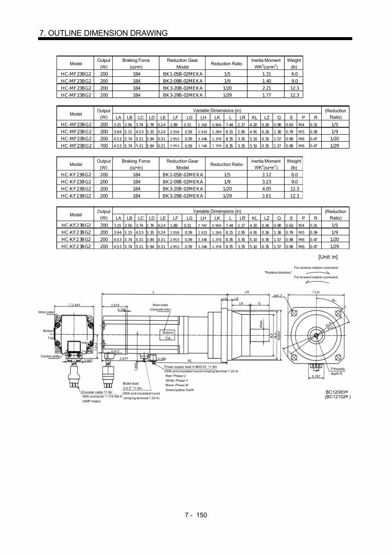
8/10/2019 Servo Motor - Instruction Manual SH(NA)-3181-D (03.00)
http://slidepdf.com/reader/full/servo-motor-instruction-manual-shna-3181-d-0300 229/368
7 - 150
7. OUTLINE DIMENSION DRAWING
ModelOutput
(W)Braking Force
(oz•in)Reduction Gear
ModelReduction Ratio
Inertia MomentWK2(oz•in 2)
Weight(lb)
HC-MF23BG2 200 184 BK1-05B-02MEKA 1/5 1.31 6.0HC-MF23BG2 200 184 BK2-09B-02MEKA 1/9 1.40 9.0HC-MF23BG2 200 184 BK3-20B-02MEKA 1/20 2.21 12.3
HC-MF23BG2 200 184 BK3-29B-02MEKA 1/29 1.77 12.3
Variable Dimensions (in)Model
Output(W) LA LB LC LD LE LF LG LH LK L LR KL LZ Q S P R
(ReductionRatio)
HC-MF23BG2 200 3.15 2.56 3.74 2.76 0.24 1.89 0.31 2.362 0.906 7.44 2.17 4.20 0.26 0.98 0.63 M4 0.31 1/5HC-MF23BG2 200 3.94 3.15 4.53 3.35 0.24 2.559 0.39 2.913 1.299 8.15 2.95 4.91 0.26 1.38 0.79 M5 0.39 1/9HC-MF23BG2 200 4.53 3.74 5.31 3.94 0.31 2.953 0.39 3.346 1.378 8.35 3.35 5.10 0.35 1.57 0.98 M6 0.47 1/20HC-MF23BG2 200 4.53 3.74 5.31 3.94 0.31 2.953 0.39 3.346 1.378 8.35 3.35 5.10 0.35 1.57 0.98 M6 0.47 1/29
ModelOutput
(W)Braking Force
(oz•in)Reduction Gear
ModelReduction Ratio
Inertia MomentWK2(oz•in 2)
Weight(lb)
HC-KF23BG2 200 184 BK1-05B-02MEKA 1/5 3.12 6.0HC-KF23BG2 200 184 BK2-09B-02MEKA 1/9 3.23 9.0HC-KF23BG2 200 184 BK3-20B-02MEKA 1/20 4.05 12.3
HC-KF23BG2 200 184 BK3-29B-02MEKA 1/29 3.61 12.3
Variable Dimensions (in)Model
Output(W) LA LB LC LD LE LF LG LH LK L LR KL LZ Q S P R
(ReductionRatio)
HC-KF23BG2 200 3.15 2.56 3.74 2.76 0.24 1.89 0.31 2.362 0.906 7.44 2.17 4.20 0.26 0.98 0.63 M4 0.31 1/5HC-KF23BG2 200 3.94 3.15 4.53 3.35 0.24 2.559 0.39 2.913 1.299 8.15 2.95 4.91 0.26 1.38 0.79 M5 0.39 1/9HC-KF23BG2 200 4.53 3.74 5.31 3.94 0.31 2.953 0.39 3.346 1.378 8.35 3.35 5.10 0.35 1.57 0.98 M6 0.47 1/20HC-KF23BG2 200 4.53 3.74 5.31 3.94 0.31 2.953 0.39 3.346 1.378 8.35 3.35 5.10 0.35 1.57 0.98 M6 0.47 1/29
Motor plate(Opposite side)
L
LELG
Top
Bottom
LK
LR
P threads,depth R
Q
"Rotation direction"For forward rotation command
For reverse rotation command
Power supply lead 4-AWG19 11.8in(With end-insulated round crimping terminal 1.25-4)
Brake lead
2-0.3 11.8in(With end-insulated roundcrimping terminal 1.25-4)
2
Encoder cable 11.8inWith connector 1-172169-9(AMP make)
Red: Phase UWhite: Phase VBlack: Phase W
Green/yellow: Earth
Top
Bottom
S h 6
L F L H L B h 7
L C L A
0.787
4- LZLD
4 5 °
Top
Bottom
Motor plate
Caution plate2.677 KL
BC12083(BC12102 )
1.6142.4410.106
0.417
0.992
1 . 5 1 2
1 . 6 8 5
0.390
[Unit: in]

8/10/2019 Servo Motor - Instruction Manual SH(NA)-3181-D (03.00)
http://slidepdf.com/reader/full/servo-motor-instruction-manual-shna-3181-d-0300 230/368
7 - 151
7. OUTLINE DIMENSION DRAWING
ModelOutput
(W)Braking Force
(oz•in)Reduction Gear
ModelReduction Ratio
Inertia MomentWK2(oz•in 2)
Weight(lb)
HC-MF43BG2 400 184 BK2-05B-04MEKA 1/5 1.88 9.5HC-MF43BG2 400 184 BK3-09B-04MEKA 1/9 2.03 13.0HC-MF43BG2 400 184 BK4-20B-04MEKA 1/20 2.59 17.9
HC-MF43BG2 400 184 BK4-29B-04MEKA 1/29 2.11 17.9
Variable Dimensions (in)Model
Output(W) LA LB LC LD LE LF LG LH LK L LR KL LZ Q S P R
(ReductionRatio)
HC-MF43BG2 400 3.94 3.15 4.53 3.35 0.24 2.559 0.39 2.913 1.299 8.50 2.95 5.18 0.26 1.38 0.79 M5 0.39 1/5HC-MF43BG2 400 4.53 3.74 5.31 3.94 0.31 2.953 0.39 3.346 1.378 9.33 3.35 6.01 0.35 1.57 0.98 M6 0.47 1/9HC-MF43BG2 400 5.31 4.33 6.10 4.53 0.31 3.543 0.47 3.937 1.575 9.57 3.94 6.24 0.43 1.97 1.26 M8 0.63 1/20HC-MF43BG2 400 5.31 4.33 6.10 4.53 0.31 3.543 0.47 3.937 1.575 9.57 3.94 6.24 0.43 1.97 1.26 M8 0.63 1/29
ModelOutput
(W)Braking Force
(oz•in)Reduction Gear
ModelReduction Ratio
Inertia MomentWK2(oz•in 2)
Weight(lb)
HC-KF43BG2 400 184 BK2-05B-04MEKA 1/5 4.76 9.5HC-KF43BG2 400 184 BK3-09B-04MEKA 1/9 4.92 13.0HC-KF43BG2 400 184 BK4-20B-04MEKA 1/20 5.47 17.9
HC-KF43BG2 400 184 BK4-29B-04MEKA 1/29 5.03 17.9
Variable Dimensions (in)Model
Output(W) LA LB LC LD LE LF LG LH LK L LR KL LZ Q S P R
(ReductionRatio)
HC-KF43BG2 400 3.94 3.15 4.53 3.35 0.24 2.559 0.39 2.913 1.299 8.50 2.95 5.18 0.26 1.38 0.79 M5 0.39 1/5HC-KF43BG2 400 4.53 3.74 5.31 3.94 0.31 2.953 0.39 3.346 1.378 9.33 3.35 6.01 0.35 1.57 0.98 M6 0.47 1/9HC-KF43BG2 400 5.31 4.33 6.10 4.53 0.31 3.543 0.47 3.937 1.575 9.57 3.94 6.24 0.43 1.97 1.26 M8 0.63 1/20HC-KF43BG2 400 5.31 4.33 6.10 4.53 0.31 3.543 0.47 3.937 1.575 9.57 3.94 6.24 0.43 1.97 1.26 M8 0.63 1/29
LELG
LK LR
Q
4 5 °
With connector 1-172169-9(AMP make)
Motor plate
Bottom
Top
Power supply lead 4-AWG19 11.8in
(With end-insulated round crimping terminal 1.25-4) Red: Phase U White: Phase V Black: Phase W Green/yellow: EarthEncoder cable 11.8in
P threads,depth R
For forward rotation command"Rotation direction"
For reverse rotation command
Brake lead
2-0.3 11.8in(With end-insulated roundcrimping terminal 1.25-4)
2
S h 6
L F L H
L B h 7
L C L A
4- LZLD
(BC12103 )BC12084
0.787
Bottom
Top
Caution plate
LKMotor plate(Opposite side)
Bottom
Top
KL
2.677
1.6142.441
0.106
0.4170.992
1 . 5 1 2
1 . 6 8 5
0.390
[Unit: in]

8/10/2019 Servo Motor - Instruction Manual SH(NA)-3181-D (03.00)
http://slidepdf.com/reader/full/servo-motor-instruction-manual-shna-3181-d-0300 231/368
7 - 152
7. OUTLINE DIMENSION DRAWING
ModelOutput
(W)Braking Force
(oz•in)Reduction Gear
ModelReduction Ratio
Inertia MomentWK2(oz•in 2)
Weight(lb)
HC-MF73BG2 750 340 BK3-05B-08MEKA 1/5 6.00 16.1HC-MF73BG2 750 340 BK4-09B-08MEKA 1/9 6.04 21.2HC-MF73BG2 750 340 BK5-20B-08MEKA 1/20 6.24 28.7
HC-MF73BG2 750 340 BK5-29B-08MEKA 1/29 5.66 28.7
Variable Dimensions (in)Model
Output(W) LA LB LC LD LE LF LG LH LK L LR KL LZ Q S P R
(ReductionRatio)
HC-MF73BG2 750 4.53 3.74 5.31 3.94 0.31 2.953 0.39 3.346 1.378 9.74 3.35 6.17 0.35 1.57 0.98 M6 0.47 1/5HC- MF73BG2 750 5.31 4.33 6.10 4.53 0.31 3.543 0.47 3.937 1.575 11.16 3.94 7.59 0.43 1.97 1.26 M8 0.63 1/9HC- MF73BG2 750 5.91 4.92 6.89 5.12 0.39 4.134 0.59 4.528 1.693 11.16 4.53 7.59 0.55 2.36 1.57 M10 0.79 1/20HC- MF73BG2 750 5.91 4.92 6.89 5.12 0.39 4.134 0.59 4.528 1.693 11.16 4.53 7.59 0.55 2.36 1.57 M10 0.79 1/29
Motor plate(Opposite side)
LELG 4- LZ
Top
Bottom
LK
LR
Q
"Rotation direction"For forward rotation command
For reverse rotation command
Power supply lead 4-AWG19 11.8in (With end-insulated round crimping terminal 1.25-4)
Brake lead2-0.3 11.8in(With end-insulated roundcrimping terminal 1.25-4)
2Encoder cable 11.8inWith connector 1-172169-9(AMP make)
Red: Phase UWhite: Phase VBlack: Phase W
Green/yellow: Earth
4 5 °
P threads,depth R
S h 6
L F L H
L B h 7
L
Motor plate
Caution plate
Top
Bottom
Top
Bottom
L C L A
2.835
KL
LD
BC12085
1.5353.228
0.106
0.992
1 . 9 1 7
0.433 0.390
2 . 2 8 7
[Unit: in]

8/10/2019 Servo Motor - Instruction Manual SH(NA)-3181-D (03.00)
http://slidepdf.com/reader/full/servo-motor-instruction-manual-shna-3181-d-0300 232/368
7 - 153
7. OUTLINE DIMENSION DRAWING
(5) EN•UL/C-UL Standard-compliant models(a) Standard (without electromagnetic brake, without reduction gear)
Variable Dimensions (in)Model
Output(W) L KL
Inertia MomentWK2(oz•in 2)
Weight(lb)
HC-MF053-UE 50 3.52 1.48 0.10 1.1HC-MF13-UE 100 4.11 2.07 0.16 1.3HC-KF053-UE 50 3.52 1.48 0.30 1.1HC-KF13-UE 100 4.11 2.07 0.47 1.3
Motor plate
Caution plate
Bottom
Top
Bottom
Top
Encoder cable11.8in
Encoder cable 11.8inWith connector 1-172169-9(AMP make)
Power supply lead 4-AWG19 11.8in(With end-insulated round crimping terminal 1.25-4)
Red: Phase UWhite: Phase VBlack: Phase WGreen/yellow: Earth
Motor plate(Opposite side)
Bottom
Top
Bottom
Top
L 0.984
0.197 0.098
KLTUV plate
1 . 1 8 1
V-10A
2- 0.177
4 5 °
1.575
1 . 4 0 6
0.787
BC07328A
0.390V ring
1.594
1.654
0.268
0.992
1 . 1 3 0
0 . 3 1 5
1 .8 1 1
[Unit: in]
Variable Dimensions (in)Model
Output(W) L KL
Inertia MomentWK2(oz•in 2)
Weight(lb)
HC-MF23-UE 200 4.27 2.28 0.49 2.6HC-MF43-UE 400 5.26 3.19 0.77 3.7HC-KF23-UE 200 4.27 2.28 2.35 2.6HC-KF43-UE 400 5.26 3.19 0.72 3.7
Motor plate
Caution plate
plate
Bottom
Top
Bottom
Top
Bottom
Top
0.390
L 1.181
0.1180.276Motor plate
(Opposite side)
Bottom
Top
KL
V ring
V-16A
Encoder cable 11.8inWith connector 1-172169-9(AMP make)
Power supply lead 4-AWG19 11.8in(With end-insulated round crimping terminal 1.25-4)
Red: Phase UWhite: Phase VBlack: Phase WGreen/yellow: Earth
0.787
BC07329A
1 . 6 8 5
4 5 °4- 0.228
2.362
0 . 5 5 1
1 . 9 6 9
TUV 1.6142.441
0.106
0.417
0.992
1 . 5 1 2
2 .7 5 6
[Unit: in]

8/10/2019 Servo Motor - Instruction Manual SH(NA)-3181-D (03.00)
http://slidepdf.com/reader/full/servo-motor-instruction-manual-shna-3181-d-0300 233/368
7 - 154
7. OUTLINE DIMENSION DRAWING
ModelOutput
(W)Inertia Moment
WK2(oz•in 2)Weight
(lb)
HC-MF73-UE 750 3.69 6.8
Encoder cable 11.8inWith connector 1-172169-9(AMP make)
Motor plate(Opposite side)
Motor plate
Caution plate0.992
1 . 9 1 7
TUV plate
3.228
Bottom
Top
Bottom
Top
5.905
1.535
0.106
Bottom
Top
0.433 0.390
3.740
1.575
0.1180.315
0 . 7 4 8
2 . 7 5 6
Power supply lead 4-AWG19 11.8in(With end-insulated round crimping terminal 1.25-4)Red: Phase UWhite: Phase V
Black: Phase WGreen/yellow: Earth
V ringV-25A
4 5 °4- 0.260
3.150
2 . 3 0 3
0.787
BC07330A
3 .5 4 3
[Unit: in]
(b) With electromagnetic brakeVariable Dimensions (in)
ModelOutput
(W) L KLBraking Force
(oz•in)Inertia Moment
WK2(oz•in 2)Weight
(lb)
HC-MF053B-UE 50 4.63 1.48 0.12 2.0HC-MF13B-UE 100 5.22 2.08 0.18 2.2HC-KF053B-UE 50 4.63 1.48 0.31 2.0HC-K F13B-UE 100 5.22 2.08
45
0.48 2.2
Motor plate(Opposite side)
L
TUV plate
Encoder cable 11.8inWith connector 1-172169-9(AMP make)
Brake lead2-0.3 2 11.8in
(With end-insulated roundcrimping terminal 1.25-4)
Power supply lead 4-AWG19 11.8in(With end-insulated round crimping terminal 1.25-4)
Red: Phase UWhite: Phase VBlack: Phase WGreen/yellow: Earth
B1,B2
KL
Motor plate
Caution plate
Top
Bottom
Top
Bottom
V-10A
V ring
4 5 °
BC07369A
Top
Bottom
Top
Bottom
1.594
1.654
0.2680.992
1 . 1 3 0
0.9840.197 0.098
1 . 1 8 1
0 . 3 1 5
1.575
1 . 4 0 6
0.787
1 .8 1 1
[Unit: in]
2- 0.177

8/10/2019 Servo Motor - Instruction Manual SH(NA)-3181-D (03.00)
http://slidepdf.com/reader/full/servo-motor-instruction-manual-shna-3181-d-0300 234/368
7 - 155
7. OUTLINE DIMENSION DRAWING
Variable DimensionsModel
Output(W) L KL
Braking Force(oz•in)
Inertia MomentWK2(oz•in 2)
Weight(lb)
HC-MF23B-UE 200 5.53 2.28 0.47 3.7HC-MF43B-UE 400 6.52 3.19 1.04 4.9HC-KF23B-UE 200 5.53 2.28 2.62 3.7
HC-K F43B-UE 400 6.52 3.19
184
3.99 4.9
Encoder cable 11.8inWith connector 1-172169-9(AMP make)
Brake lead2-0.3 11.8in(With end-insulated round crimping terminal 1.25-4)B1,B2
Power supply lead 4-AWG19 11.8in(With end-insulated round crimping terminal 1.25-4)
Red: Phase UWhite: Phase VBlack: Phase WGreen/yellow: Earth
Motor plate(Opposite side)
Bottom
Top
Motor plate
Caution plate
Top
Bottom
Bottom
Top
Top
Bottom
TUV plate
L
KL
0.390
V-16A
4 5 °
BC07354A
V ring
1.6142.441 0.106
0.4170.992
1 . 5 1 2
1.1810.1180.276 4- 0.228
0 . 5 5 1
1 . 9 6 9
0.787
1 . 6 8 5
2.362
2 .7 5 6
[Unit: in]
2
ModelOutput
(W)Braking Force
(oz•in)Inertia Moment
WK2(oz•in 2)Weight
(lb)
HC-MF73B-UE 750 340 4.10 9.3
Encoder cable 11.8inWith connector 1-172169-9(AMP make)
Brake lead2-0.3 2 11.8in(With end-insulated round crimping terminal 1.25-4)B1,B2
Power supply lead 4-AWG19 11.8in(With end-insulated round crimping terminal 1.25-4)
Red: Phase UWhite: Phase VBlack: Phase WGreen/yellow: Earth
BC07606A
4 5 °
V-25A
Bottom
Top
Motor plate
Caution plate
plateTUV
Bottom
Top
Bottom
Top
Motor plate(Opposite side)
7.303
V ring
0.992
1 . 9 1 7
3.228 1.535
0.106
0.433 0.390
3.740
1.575
0.1180.315
0 . 7 4 8
2 . 7 5 6
4- 0.260
3.150
2 . 2 8 7
0.787
3 .5 4 3
[Unit: in]

8/10/2019 Servo Motor - Instruction Manual SH(NA)-3181-D (03.00)
http://slidepdf.com/reader/full/servo-motor-instruction-manual-shna-3181-d-0300 235/368
7 - 156
7. OUTLINE DIMENSION DRAWING
7.2.2 HA-FF Series
(1) Standard (without electromagnetic brake, without reduction gear)Variable Dimensions (in)
ModelOutput
(W) LInertia Moment
WK2(oz•in 2)Weight
(lb)
HA-FF053 50 4.17 0.34 2.9HA-FF13 100 4.84 0.52 3.3
Power supply cableVCTF 0.05 19.7in(With end-insulated round crimping terminal 0.05-4)
1.535 0.10.24
1.18
4 5 °
2
1 . 5 4
Caution plate
L
V ring
1 . 5 4
Earth terminal M3 screw(Opposite side)
BottomTop
Red: Phase U White: Phase V Black: Phase W
[Unit: in]
Encoder cable 11.8inWith connector 172169-9(AMP make)
Bottom
Top
Motor plate
Z694731
1 . 8 5
1 . 9 7
0 . 3 1
2 . 3 6
2 .6 8
4- 0.18
2.13
Variable Dimensions (in)Model
Output(W) L
Inertia MomentWK2(oz •in 2)
Weight(lb)
HA-FF23 200 5.138 1.91 5.1HA-FF33 300 5.83 2.73 5.7
1.535 0.120.31
1.18
4 5 °
1 . 5 4
L
1 . 9 7
Earth terminal, M3 screw
A
A
0.63 0.16
0.98
0.16
Section AA
0 . 1 0
0 . 1 6Power supply cable
VCTF 0.05 19.7in(With end-insulated roundcrimping terminal 0.05-4)
2
Caution plate
V ring
BottomTop
Red: Phase U White: Phase V Black: Phase W
[Unit: in]
Encoder cable 11.8inWith connector 172169-9(AMP make)
Bottom
Top
Motor plate
Z694732
M4 0.7 threads,depth 0.59
2.99
4- 0.22
3. 5 43 .9 4
2 . 7 6
0.43
1 . 8 5

8/10/2019 Servo Motor - Instruction Manual SH(NA)-3181-D (03.00)
http://slidepdf.com/reader/full/servo-motor-instruction-manual-shna-3181-d-0300 236/368
7 - 157
7. OUTLINE DIMENSION DRAWING
Variable Dimensions (in)Model
Output(W) L
Inertia MomentWK2(oz •in 2)
Weight(lb)
HA-FF43 400 6.08 5.33 9.3HA-FF63 600 6.67 6.56 10.6
Moter plate
1.535 0.120.39
[Unit:in]1.57
4 5 °
1 . 5 4
L
V ring 2 . 4 4
Caution plate
A
A
0.20
1.38
0.20
Section AA
0 . 1 2
0 . 2 0
0.984
BottomTop
Power supply cableVCTF 3-0.05 19.7in
(With end-insulated round crimping terminal 0.05-4)
2
Red:Phase UWhite:Phase VBlack:Phase W
Encoder cable 11.8inWith connector 172169-9(AMP make)
Earth terminal M3 screw
Bottom
Top
4- 0.35
4. 5 3 5 .3 1
3.94
3 . 7 4
0.63
1 . 8 5
M5 0.8 threads,depth 0.79
Z694733
(2) With electromagnetic brakeVariable Dimensions (in)
ModelOutput
(W) LBraking Force
(oz•in)Inertia Moment
WK2(oz •in 2)Weight
(lb)
HA-FF053B 50 5.551 55 0.437 3.5HA-FF13B 100 6.22 55 0.618 4.0
Moter plate
1.535 0.100.24
[Unit:in]
Top
Bottom
1.18
4 5 °
BottomTop
1 . 5 4
Caution plate
LEarth terminal M3 screw(Opposite side)
V ring
1 . 5 4
Power supply cableVCTF 3-0.05 19.7in(With end-insulated round crimping terminal 0.05-4)
2
Red:Phase UWhite:Phase VBlack:Phase W
Encoder cable 118inWith connector 172169-9(AMP make)
Brake leadVCTF 2-0.02 11.8in(With end-insulated round crimping terminal 0.05-4)
2
1 . 8 5
0 . 3 1
1 . 9 7
4- 0.18
2 . 3 6
2 .6 8
2.13
Z694734

8/10/2019 Servo Motor - Instruction Manual SH(NA)-3181-D (03.00)
http://slidepdf.com/reader/full/servo-motor-instruction-manual-shna-3181-d-0300 237/368
7 - 158
7. OUTLINE DIMENSION DRAWING
Variable Dimensions (in)Model
Output(W) L
Braking Force(oz•in)
Inertia MomentWK2(oz•in 2)
Weight(lb)
HA-FF23B 200 6.614 170 2.641 6.4HA-FF33B 300 7.303 170 3.461 7.1
Moter plate
1.535 0.120.31
[Unit:in]
Top
Bottom
1.18
4 5 °
BottomTop
1 . 5 4
Caution plate
L
V ring 1 . 9 7
A
A
0.16
0.98
0.16
Section AA
0 . 1 0
0 . 1 6
0.63
Earth terminalM3 screw
M4 0.7 threads,depth 0.59
Power supply cableVCTF 3-0.05 1.97in(With end-insulated round crimping terminal 0.05-4)
2
Red:Phase UWhite:Phase VBlack:Phase W
Encoder cable 11.8inWith connector 172169-9(AMP make)
Brake leadVCTF 2-0.02 19.7in(With end-insulated round crimping terminal 0.05-4)
2
Z694735
2.99
4- 0.22
3. 5 4
3 . 9
4
0.43
2 . 7 6
.
Variable Dimensions (in)Model
Output(W) L
Braking Force(oz•in)
Inertia MomentWK2(oz•in 2)
Weight(lb)
HA-FF43B 400 7.54 326 7.244 11.0HA-FF63B 600 8.13 326 8.475 12.3
Moter plate
1.535 0.120.39
[Unit:in]
Top
Bottom
1.57
4 5 °
BottomTop
1 . 5 4
Caution plate
L
V ring 2 . 4 4
Earth terminal M3 screw
A
A
0.20
1.38
M5 0.8 threads,depth 0.79
0.20
Section AA
0 . 1 2
0 . 2 0
0.984
Power supply cableVCTF 3-0.05 19.7in(With end-insulated roundcrimping terminal 0.05-4)
2
Red:Phase UWhite:Phase VBlack:Phase W
Encoder cable 11.8inWith connector 172169-9(AMP make)
Brake leadVCTF 2-0.02 19.7in(With end-insulated round crimping terminal 0.05-4)
2
1 . 8
5
3 . 7 4
0.63
3.94
4- 0.35
4. 5 3 5 . 3 1
Z694736

8/10/2019 Servo Motor - Instruction Manual SH(NA)-3181-D (03.00)
http://slidepdf.com/reader/full/servo-motor-instruction-manual-shna-3181-d-0300 238/368
7 - 159
7. OUTLINE DIMENSION DRAWING
(3) With reduction gear for general industrial machine(a) Without electromagnetic brake
ModelOutput
(W)Reduction
Gear ModelReduction Ratio
(Actual Reduction Ratio)Inertia Moment
WK2(oz•in 2)Backlash
Weight(lb)
Output Shaft RotationDirection
1/5(9/44)1/10(3/29) 0.369
Same as that of motorshaft
1/20(99/1972)HC-FF053G1 50 GR-S-10
1/30(144/4205 0.342
40min.to 1.5
˚ 5.5Opposite to that of motor shaft
Moter plate
1.54
0.12
1.3
3.54
Top
Bottom
BottomTop
1 . 5 4
Caution plate
7.20
3 . 5 4
A
A
0.2
Section AA
0 . 1 2
0 . 2
4.173
Earth terminal M3 screw(Opposite side)
3.031
0.11
1.5
0 . 7 1
4 5 °
[Unit:in]"Rotation direction"
For forward rotation command
For reverse rotation command
Power supply cable VCTF 3-0.05 19.7in(With end-insulated round crimping terminal 0.05-4)
Red:Phase UWhite:Phase VBlack:Phase W
Encoder cable 11.8inWith connector 172169-9(AMP make)
2
Z694764
4 .0 9
4- 0.26 (Note)
0.59
Note: Four M6 90 through bolts are provided.
1 . 8 5
1 . 3 4
ModelOutput
(W)Reduction
Gear ModelReduction Ratio
(Actual Reduction Ratio)Inertia Moment
WK2(oz•in 2)Backlash
Weight(lb)
Output Shaft RotationDirection
1/5(9/44)1/10(3/29)
0.547 Same as that of motor
shaft
1/20(25/1972)HC-FF13G1 100 GR-S-10
1/30(25/4205) 0.519
40min.to 1.5
˚ 6.0Opposite to that of motor shaft
Motor plate
1.54
0.12
1.3
3.54
Top
Bottom
2
BottomTop
1 . 5 4
Caution plate
7.87
3 . 5 4
A
A
0.2
Section AA
0 . 1 2
0 . 2
4.843
Earth terminal M3 screw(Opposite side)
3.031
0.11
1.5
0 . 7 1
4 5 °
[Unit:in]"Rotation direction"
For forward rotation command
For reverse rotation command
Power supply cableVCTF 3-0.05 19.7in(With end-insulated round c rimping terminal 0.05-4)
Red:Phase UWhite:Phase VBlack:Phase W
Encoder cable 11.8inWith connector 172169-9(AMP make)
Note: Four M6 90 through bolts are provided.
1 . 8 5
Z694765
1 . 3 4
0.59
4 .0 9
4- 0.26 (Note)

8/10/2019 Servo Motor - Instruction Manual SH(NA)-3181-D (03.00)
http://slidepdf.com/reader/full/servo-motor-instruction-manual-shna-3181-d-0300 239/368
7 - 160
7. OUTLINE DIMENSION DRAWING
ModelOutput
(W)Reduction
Gear ModelReduction Ratio
(Actual Reduction Ratio)Inertia Moment
WK2(oz•in 2)Backlash
Weight(lb)
Output Shaft RotationDirection
1/5(57/280)1/10(39/400)
2.039
1/20(51/980)HC-FF23G1 200 GR-S-20
1/30(1/30)
2.023
40min.to 1.5
˚ 11 Same as that of
motor shaft
Motor plate
1.540.12
0.98
5.71
Top
Bottom
1 . 5 4
Caution plate
8.445
5 . 9 1
A
A
0.2
Section AA
0 . 1 2
0 . 2
5.138
1.28
0.94
0.47
0 . 5 9
3.307
4 5 °
3 . 0 5
2 . 8 5
[Unit:in]"Rotation direction"
For forward rotation command
For reverse rotation command
M6 threads,depth 0.39
Earth terminal M3 screw(Opposite side)
Bottom
Top
Power supply cable VCTF 3-0.05 19.7in(With end-insulated round crimping terminal 0.05-4)
Red:Phase UWhite:Phase VBlack:Phase W
Encoder cable 11.8inWith connector 172169-9(AMP make)
2
Z694766
1 . 8 5 5 .
1 2
0.63
7 . 0 9
4- 0.39
ModelOutput
(W)Reduction
Gear ModelReduction Ratio
(Actual Reduction Ratio)Inertia Moment
WK2(oz•in 2)Backlash
Weight(lb)
Output Shaft RotationDirection
1/5(19/94)1/10(39/376)
2.980
1/20(72/1303)HC-FF33G1 300 GR-S-30
1/30(11/329)2.939
40min. to 1.5
˚ 14.3 Same as that of
motor shaft
Motor plate
1.54 0.12
0.98
5.71
Top
Bottom
BottomTop
1 . 5 4
Caution plate
9.84
6 . 3
A
A
0.24
Section AA
0 . 1 4
0 . 2 4
5.827
1.48
1.1
0.47
0 . 7 1
4.016
M6 threads,depth 0.39
4 5 °
3 . 4 9
2 . 8 5
[Unit:in]"Rotation direction"
For forward rotation command
For reverse rotation command
Earth terminal M3 screw(Opposite side)
Power supply cable VCTF 3-0.05 19.7in(With end-insulated round crimping terminal 0.05-4)
Red:Phase UWhite:Phase VBlack:Phase W
Encoder cable 11.8inWith connector 172169-9(AMP make)
2
Z694767
1 . 8 5
5 . 1 2
0.75
7 . 0 9
4- 0.39

8/10/2019 Servo Motor - Instruction Manual SH(NA)-3181-D (03.00)
http://slidepdf.com/reader/full/servo-motor-instruction-manual-shna-3181-d-0300 240/368
7 - 161
7. OUTLINE DIMENSION DRAWING
ModelOutput
(W)Reduction
Gear ModelReduction Ratio
(Actual Reduction Ratio)Inertia Moment
WK2(oz•in 2)Backlash
Weight(lb)
Output ShaftRotation Direction
1/5(19/94)1/10(39/376)
5.577
1/20(72/1363)HC-FF43G1 400 GR-S-40
1/30(11/329)
5.536
40min.to 1.5
˚ 17.6 Same as that of
motor shaft
Motor plate
1.54 0.12
0.98
5.71
Top
Bottom
BottomTop
1 . 5 4
Caution plate
10.177
6 . 3
A
A
0.24
Section AA
0 . 1 4
0 . 2 4
6.083
Earth terminal M3 screw(Opposite side)
1.48
1.1
0.47
0 . 7 1
4.094
M6 threads,depth 0.39
3 . 4 9
2 . 8 5
[Unit:in]"Rotation direction"
For forward rotation command
For reverse rotation command
2Power supply cable VCTF 3-0.05 19.7in(With end-insulated round crimping terminal 0.05-4)
Red:Phase UWhite:Phase VBlack:Phase W
Encoder cable 11.8inWith connector 172169-9(AMP make) Z694768
0.75
1 . 8 5 5 .
1 2
4- 0.39
7 . 0 9
ModelOutput
(W)Reduction
Gear ModelReduction Ratio
(Actual Reduction Ratio)Inertia Moment
WK2(oz•in 2)Backlash
Weight(lb)
Output ShaftRotation Direction
1/5(10/49)1/10(243/2401)
7.326
1/20(153/2891)HC-FF63G1 600 GR-S-60
1/30(27/784)7.217
40min.to 1.5
˚ 28.7 Same as that of
motor shaft
1.54 0.12
1.26
7.28
Top
Bottom
1 . 5 4
Caution plate
10.81
7 . 5 8
A
A
0.24
Section AA
0 . 1 4
0 . 2 4
6.673
Earth terminal M3 screw(Opposite side)
1.83
1.42
0.47
0 . 7 9
4.134
M8 threads,depth 0.47
3 . 9 4
3 . 6 4
4 5 °
[Unit:in]"Rotation direction"
For forward rotation command
For reverse rotation command
Motor plateBottomTop
2Power supply cable VCTF 3-0.05 19.7in(With end-insulated round crimping terminal 0.05-4)
Red:Phase UWhite:Phase VBlack:Phase W
Encoder cable 11.8inWith connector 172169-9(AMP make) Z694769
1 . 8 5 6 .
6 9
0.87
4- 0.47
8. 8 6

8/10/2019 Servo Motor - Instruction Manual SH(NA)-3181-D (03.00)
http://slidepdf.com/reader/full/servo-motor-instruction-manual-shna-3181-d-0300 241/368
7 - 162
7. OUTLINE DIMENSION DRAWING
(b) With electromagnetic brake
ModelOutput
(W)Braking Force
(oz•in)Reduction
Gear ModelReduction Ratio
(Actual Reduction Ratio)Inertia Moment
WK2(oz•in 2)Backlash
Weight(lb)
Output Shaft RotationDirection
1/5(9/44)1/10(3/29)
0.465Same as that of
motor shaft
1/20(99/1972)HA-FF053BG1 50 55 GR-S-101/30(144/4205)
0.437
40min.to 1.5 ˚ 6.2 Opposite to that of
motor shaft
Motor plate
1.54
0.125.5513.54
Top
Bottom
1.5
4 5 °
Bottom
1 . 5 4
Caution plate
8.583
3 . 5 4
Earth terminal M3 screw(Opposite side)
A
A
1.3
0.2
Section AA
0 . 1 2
0 . 2
0.11
Brake cableVCTF 2-0.02 19.7in(With end-insulated round crimping terminal 0.05-4)
2
3.031
0 . 7 1
[Unit:in]"Rotation direction"
For forward rotation command
For reverse rotation command
Top
Power supply cable VCTF 3-0.05 19.7in(With end-insulated round crimping terminal 0.05-4)
Red:Phase UWhite:Phase VBlack:Phase W
Encoder cable 11.8inWith connector 172169-9(AMP make)
2
Z694770
Note: Four M6 90 through bolts are provided.
1 . 8 5 1 .
3 4
0.59
4- 0.26 (Note)
4. 0 9
ModelOutput
(W)Braking Force
(oz•in)Reduction
Gear ModelReduction Ratio
(Actual Reduction Ratio)Inertia Moment
WK2(oz•in 2)Backlash
Weight(lb)
Output Shaft RotationDirection
1/5(9/44)
1/10(3/29) 0.629
Same as that of
motor shaft1/20(99/1972)
HA-FF13BG1 100 55 GR-S-10
1/30(144/4205) 0.601
40min.to 1.5
˚ 6.6Opposite to that of
motor shaft
1.54
0.126.223.54
Top
Bottom
1.5
4 5 °
1 . 5 4
Caution plate
9.252
3 . 5 4
Earth terminal M3 screw(Opposite side)
A
A
1.3
0.2
Section AA
0 . 1 2
0 . 2
0.11
2
3.031
0 . 7 1
[Unit:in]"Rotation direction"
For forward rotation command
For reverse rotation command
Encoder cable 11.8inWith connector 172169-9(AMP make)
Power supply cable VCTF 3-0.05 19.7in(With end-insulated round crimping terminal 0.05-4)Red:Phase UWhite:Phase VBlack:Phase W
Brake cableVCTF 2-0.02 19.7in(With end-insulated round crimping terminal 0.05-4)
2
Motor plateBottom
Top
1 . 8 5 1 .
3 4
0.59
4- 0.26 (Note)
4. 0 9
Note: Four M6 90 through bolts are provided.
Z694771

8/10/2019 Servo Motor - Instruction Manual SH(NA)-3181-D (03.00)
http://slidepdf.com/reader/full/servo-motor-instruction-manual-shna-3181-d-0300 242/368
7 - 163
7. OUTLINE DIMENSION DRAWING
ModelOutput
(W)Braking Force
(oz•in)Reduction
Gear ModelReduction Ratio
(Actual Reduction Ratio)Inertia Moment
WK2(oz•in 2)Backlash
Weight(lb)
Output Shaft RotationDirection
1/5(57/280)1/10(39/400)
2.745
1/20(51/980)HA-FF 23BG1 200 170 GR-S-20
1/30(1/30)
2.734
40min.to 1.5
˚ 12.3 Same as that of
motor shaft
Motor plate
1.54 0.12
0.98
5.71
Top
Bottom
Power supply cableVCTF 3-0.05 19.7in(With end-insulated round crimping terminal 0.05-4)
2
BottomTop
1 . 5 4
Caution plate
9.921
5 . 9 1
A
A0.2
Section AA
0 . 1 2
0 . 2
6.614
Earth terminal M3 screw(Opposite side)
1.28
0.94
0.47
0 . 5 9
3.307
4 5 °
3 . 0 5
2 . 8 5
Brake leadVCTF 2-0.02 19.7in(With end-insulated round crimping terminal 0.05-4)
2
[Unit:in]"Rotation direction"
For forward rotation command
For reverse rotation command
M6 threads,depth 0.39
Red:Phase UWhite:Phase VBlack:Phase W
Encoder cable 11.8inWith connector 172169-9(AMP make)
Z694772
1 . 8 5 5 .
1 2
4- 0.39
7 . 0 9
0.63
ModelOutput
(W)Braking Force
(oz•in)Reduction
Gear ModelReduction Ratio
(Actual Reduction Ratio)Inertia Moment
WK2(oz•in 2)Backlash
Weight(lb)
Output Shaft RotationDirection
1/5(19/94)1/10(39/376)
3.707
1/20(72/1363)HA-FF 33BG1 300 170 GR-S-30
1/30(11/329)
3.663
40min.to 1.5
˚ 15.9 Same as that of
motor shaft
1.54 0.12
1.1
5.71
Red:Phase UWhite:Phase VBlack:Phase W
Top
Bottom
1 . 5 4
Caution plate
11.319
6 . 3
A
A
0.24
Section AA
0 . 1 4
0 . 2 4
7.303
Earth terminal M3 screw(Opposite side)
1.48
0.98
0.47
0 . 7 1
1 . 8 5
4.016
M6 threads,
depth 0.39
4 5 °
3 . 4 9
2 . 8 5
[Unit:in]"Rotation direction"
For forward rotation command
For reverse rotation command
Brake leadVCTF 2-0.02 19.7in(With end-insulated round crimping terminal 0.05-4)
2
Motor plateBottomTop
Power supply cableVCTF 3-0.05 19.7in(With end-insulated round crimping terminal 0.05-4)
2
Encoder cable 11.8inWith connector 172169-9(AMP make)
5 . 1 2
0.75
4- 0.39
7 . 0 9
Z694773

8/10/2019 Servo Motor - Instruction Manual SH(NA)-3181-D (03.00)
http://slidepdf.com/reader/full/servo-motor-instruction-manual-shna-3181-d-0300 243/368
7 - 164
7. OUTLINE DIMENSION DRAWING
ModelOutput
(W)Braking Force
(oz•in)Reduction
Gear ModelReduction Ratio
(Actual Reduction Ratio)Inertia Moment
WK2(oz•in 2)Backlash
Weight(lb)
Output Shaft RotationDirection
1/5(19/94)1/10(39/376)
7.490
1/20(72/1363)HA-FF 43BG1 400 326 GR-S-40
1/30(11/329)
7.449
40min.to 1.5
˚ 19.6 Same as that of
motor shaft
1.54 0.12
1.1
5.71
Red:Phase UWhite:Phase VBlack:Phase W
Top
Bottom
1 . 5 4
Caution plate
11.63
6 . 3
A
A0.24
Section AA
0 . 1 4
0 . 2 4
7.539
Earth terminal M3 screw(Opposite side)
1.48
0.98
0.47
0 . 7 1
4.094
M6 threads,depth 0.39 3 .
4 9
2 . 8 5
2
[Unit:in]"Rotation direction"
For forward rotation command
For reverse rotation command
Brake leadVCTF 2-0.02 19.7in(With end-insulated round crimping terminal 0.05-4)
Motor plateBottomTop
Power supply cableVCTF 3-0.05 19.7in(With end-insulated round crimping terminal 0.05-4)
2Encoder cable 11.8inWith connector 172169-9(AMP make)
4 5 °
1 . 8 5 5 .
1 2
0.75
4- 0.39
7 . 0 9
Z694774
ModelOutput
(W)Braking Force
(oz•in)Reduction
Gear ModelReduction Ratio
(Actual Reduction Ratio)Inertia Moment
WK2(oz•in 2)Backlash
Weight(lb)
Output ShaftRotation Direction
1/5(10/49)1/10(243/2401)
9.240
1/20(153/2891)HA-FF 63BG1 600 326 GR-S-60
1/30(27/784) 9.131
40min.to 1.5
˚ 30.6 Same as that of
motor shaft
Caution plate
1.54
0.12
1.42
7.28
Top
Bottom
Power supply cableVCTF 3-0.05 19.7in(With end-insulated round crimping terminal 0.05-4)
2
1 . 5 4
12.264
7 . 5 8
A
A0.24
0 . 1 4
0 . 2 4
8.13
Earth terminal M3 screw(Opposite side)
1.83
1.26
0.47
0 . 7 9
4.1344 5 °
3 . 9 4
3 . 6 4
2
Brake leadVCTF 2-0.02 19.7in(With end-insulated round crimping terminal 0.05-4)
Motor plateBottomTop
Encoder cable 11.8inWith connector 172169-9(AMP make)
Red:Phase UWhite:Phase VBlack:Phase W
Section AAM6 threads,depth 0.47
[Unit:in]"Rotation direction"
For forward rotation command
For reverse rotation command
1 . 8 5 6 .
6 9
0.87
4- 0.47
8. 8 6
Z694775

8/10/2019 Servo Motor - Instruction Manual SH(NA)-3181-D (03.00)
http://slidepdf.com/reader/full/servo-motor-instruction-manual-shna-3181-d-0300 244/368
7 - 165
7. OUTLINE DIMENSION DRAWING
(4) With reduction gear for precision application(a) Without electromagnetic brake
ModelOutput
(W)Reduction Gear
ModelReduction Ratio
Inertia MomentWK2(oz•in 2)
BacklashWeight
(lb)
HA-FF053G2 50 BM2-05B-A5MES 1/5 0.60 3 min. max. 5.1
Motor plate
1.54
0.24
3.898
Top
Bottom
1.18
4 5 °
BottomTop
1 . 5 4
Caution Plate
8.07
Earth terminal M3 screw(Opposite side)
Earth terminal M3
0.08
0.35 0.79
[Unit:in]"Rotation direction"
For forward rotation command
For reverse rotation command
Power supply cableVCTF 3-0.05 19.7in(With end-insulated round crimping terminal 0.05-4)
2
Red:Phase UWhite:Phase VBlack:Phase W
Encoder cable 11.8inWith connector 172169-9(AMP make)
1 . 8 5 0 .
3 9
1 . 3 0
2 . 4 4 2 .
9 5 3 .5 0 3. 0 7
4- 0.18
2.91
Z694850
Variable Dimensions (in)Model
Output(W) L
Reduction Gear Model
ReductionRatio
Inertia MomentWK2(oz•in 2)
BacklashWeight
(lb)
HA-FF053G2 50 8.07 BM2-10B-A5MES 1/10 0.59 3 min. max. 5.1HA-FF053G2 50 8.07 BM2-15B-A5MES 1/15 0.57 3 min. max. 5.1HA-FF013G2 100 8.74 BM2-05B-01MES 1/5 0.78 3 min. max. 5.5
Motor plate
1.54
0.24
3.898
Top
Bottom
1.18
4 5 °
BottomTop 1 . 5 4
Caution plate
L
Earth terminal M3 screw(Opposite side)
Earth terminal M3
0.08
0.35 0.79
[Unit:in]"Rotation direction"
For forward rotation command
For reverse rotation command
Power supply cableVCTF 3-0.05 19.7in(With end-insulated round crimping terminal 0.05-4)
2
Red:Phase UWhite:Phase VBlack:Phase W
Encoder cable 11.8inWith connector 172169-9(AMP make) Z694805
2.91
4- 0.18
3. 0 7 3 .5 0
2 . 4 4
1 . 3 0
0 . 3 9
2 . 9 5
1 . 8 5
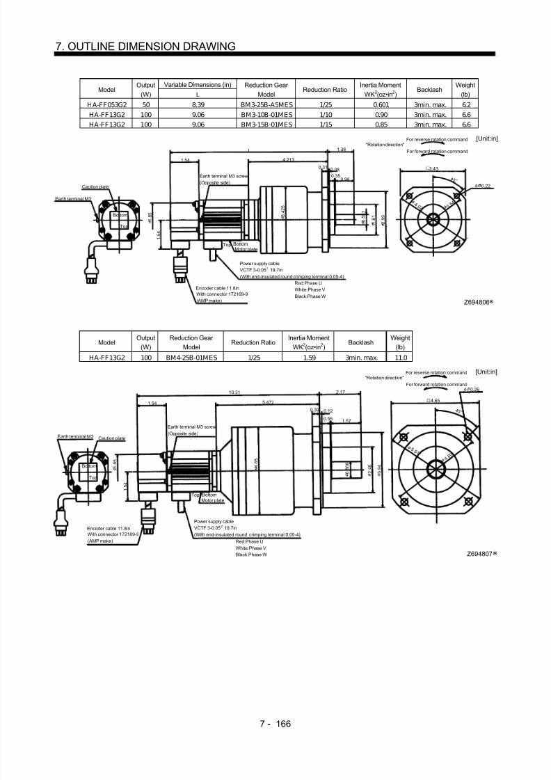
8/10/2019 Servo Motor - Instruction Manual SH(NA)-3181-D (03.00)
http://slidepdf.com/reader/full/servo-motor-instruction-manual-shna-3181-d-0300 245/368
7 - 166
7. OUTLINE DIMENSION DRAWING
Variable Dimensions (in)Model
Output(W) L
Reduction Gear Model
Reduction RatioInertia Moment
WK2(oz•in 2)Backlash
Weight(lb)
HA-FF053G2 50 8.39 BM3-25B-A5MES 1/25 0.601 3min. max. 6.2HA-FF13G2 100 9.06 BM3-10B-01MES 1/10 0.90 3min. max. 6.6HA-FF13G2 100 9.06 BM3-15B-01MES 1/15 0.85 3min. max. 6.6
Motor plate
1.54
0.31
4.213
Top
Bottom
1.38
4 5 °
BottomTop
1 . 5 4
Caution plate
L
Earth terminal M3 screw(Opposite side)
Earth terminal M3
0.080.35
0.98
[Unit:in]"Rotation direction"
For forward rotation command
For reverse rotation command
Power supply cableVCTF 3-0.05 19.7in(With end-insulated round crimping terminal 0.05-4)
2
Red:Phase UWhite:Phase VBlack:Phase W
Encoder cable 11.8inWith connector 172169-9(AMP make)
1 . 8 5
3 . 4 2 5
0 . 5 5 1
1 . 6 1
2 . 9 9
3. 5 4 4 .0 2
4- 0.22
3.43
Z694806
ModelOutput
(W)Reduction Gear
ModelReduction Ratio
Inertia MomentWK2(oz•in 2)
BacklashWeight
(lb)
HA-FF13G2 100 BM4-25B-01MES 1/25 1.59 3min. max. 11.0
Motor plate
1.54
0.39
5.472
Top
Bottom
2.17
4 5 °
BottomTop 1 . 5 4
Caution plate
10.31
Earth terminal M3 screw(Opposite side)
Earth terminal M3
0.12
0.55 1.57
4 . 6 5
[Unit:in]"Rotation direction"
For forward rotation command
For reverse rotation command
Power supply cableVCTF 3-0.05 19.7in(With end-insulated round crimping terminal 0.05-4)
2
Red:Phase U
White:Phase VBlack:Phase W
Encoder cable 11.8inWith connector 172169-9(AMP make)
1 . 8 5
0 . 8 6 6
2 . 4 0
3 . 9 4
5 .5 1
4. 8 0
4- 0.26
4.65
Z694807

8/10/2019 Servo Motor - Instruction Manual SH(NA)-3181-D (03.00)
http://slidepdf.com/reader/full/servo-motor-instruction-manual-shna-3181-d-0300 246/368
7 - 167
7. OUTLINE DIMENSION DRAWING
ModelOutput
(W)Reduction Gear
ModelReduction Ratio
Inertia MomentWK2(oz•in 2)
BacklashWeight
(lb)
HA-F F13G2 100 BL 1-45B-01M ES 1/45 1.60 3min. max. 13.2
Motor plate
1.54
0.39
5.945
Top
Bottom
3.35
4 5 °
BottomTop
1 . 5 4
Caution plate
10.79
Earth terminal M3 screw(Opposite side)
0.12
1.571.69
[Unit:in]"Rotation direction"
For forward rotation command
For reverse rotation command
Power supply cableVCTF 3-0.05 19.7in
(With end-insulated round crimping terminal 0.05-4)
2
Red:Phase UWhite:Phase VBlack:Phase W
Encoder cable 11.8inWith connector 172169-9(AMP make) Z694737
4.724- 0.47
5. 1 2 6 .1 0
3 . 9 4
2 . 7 6
0 . 9 8
1 . 8 5
4 . 0 1 6
ModelOutput
(W)Reduction Gear
ModelReduction Ratio
Inertia MomentWK2(oz•in 2)
BacklashWeight
(lb)
HA-FF 23G2 200 BM3-05B-02M ES 1/5 2.32 3min. max. 8.4
Motor plate
1.54
0.31
4.291
Top
Bottom
1.38
4 5 °
BottomTop
1 . 5 4
Caution plate
9.429
Earth terminal M3 screw(Opposite side)
0.08
0.35
0.98
[Unit:in]"Rotation direction"
For forward rotation command
For reverse rotation command
Power supply cableVCTF 3-0.05 19.7in(With end-insulated round crimping terminal 0.05-4)
2
Red:Phase UWhite:Phase VBlack:Phase W
Encoder cable 11.8inWith connector 172169-9(AMP make) Z694808
3.43
4- 0.22
3. 5 4
4 .0 2
1 . 6 1
2 . 9 9
0 . 5 5 1
3 . 4 2 5
1 . 8 5

8/10/2019 Servo Motor - Instruction Manual SH(NA)-3181-D (03.00)
http://slidepdf.com/reader/full/servo-motor-instruction-manual-shna-3181-d-0300 247/368
7 - 168
7. OUTLINE DIMENSION DRAWING
Variable Dimensions (in)Model
Output(W) L
Reduction Gear Model
Reduction RatioInertia Moment
WK2(oz•in 2)Backlash
Weight(lb)
HA-FF23G2 200 10.61 BM4-10B-02MES 1/10 3.53 3min. max. 12.8HA-FF23G2 200 10.61 BM4-15B-02MES 1/15 3.38 3min. max. 12.8HA-FF33G2 300 11.30 BM4-10B-03MES 1/10 4.35 3min. max. 13.4
Motor plate
1.540.39
5.472
Top
Bottom
2.17
4 5 °
BottomTop
1 . 5 4
Caution plate
L
Earth terminal M3 screw(Opposite side)
0.12
0.551.57
[Unit:in]"Rotation direction"
For forward rotation command
For reverse rotation command
Power supply cableVCTF 3-0.05 19.7 in(With end-insulated round crimping terminal 0.05-4)
2
Red:Phase UWhite:Phase VBlack:Phase W
Encoder cable 11.8inWith connector 172169-9(AMP make)
1 . 8 5 4 .
6 5
0 . 8 6 6
2 . 4 0
3 . 9 4
5 .5 1
4. 8 0
4- 0.26
4.65
Z694809
Variable Dimensions (in)Model
Output(W) L
Reduction Gear Model
Reduction RatioInertia Moment
WK2(oz•in 2)Backlash
Weight(lb)
HA-FF23G2 200 10.94 BL1-20B-02MES 1/20 3.99 3min. max. 15.0HA-FF23G2 200 10.94 BL1-29B-02MES 1/29 3.46 3min. max. 15.0HA-FF33G2 300 11.61 BL1-20B-03MES 1/20 4.81 3min. max. 15.7
1.540.39
5.787
Top
Bottom
3.35
4 5 °
1 . 5 4
aution plate
L
Earth terminal M3 screw(Opposite side)
0.12
1.571.69
[Unit:in]"Rotation direction"
For forward rotation command
For reverse rotation command
Motor plateBottomTop
Power supply cableVCTF 3-0.05 19.7in(With end-insulated round crimping terminal 0.05-4)
2
Red:Phase UWhite:Phase VBlack:Phase W
Encoder cable 11.8inWith connector 172169-9(AMP make) Z694738
4.72
4- 0.47
6 .1 0 5. 1 2
2 . 7 6
3 . 9 4
0 . 9 8 4 .
0 1 6
1 . 8 5

8/10/2019 Servo Motor - Instruction Manual SH(NA)-3181-D (03.00)
http://slidepdf.com/reader/full/servo-motor-instruction-manual-shna-3181-d-0300 248/368
7 - 169
7. OUTLINE DIMENSION DRAWING
Variable Dimensions (in)Model
Output(W) L
Reduction Gear Model
ReductionRatio
Inertia MomentWK2(oz•in 2)
BacklashWeight
(lb)
HA-FF23G2 200 11.77 BL2-45B-02MES 1/45 4.17 3min. max. 27.1HA-FF33G2 300 12.44 BL2-29B-03MES 1/29 83.9 3min. max. 27.8HA-FF33G2 300 12.44 BL2-45B-03MES 1/45 4.99 3min. max. 27.8
Motor plate
1.540.47
6.614
Top
Bottom
3.94
4 5 °
BottomTop
1 . 5 4
Cautionplate
0.12
2.171.69L
[Unit:in]
"Rotation direction"
For forward rotation command
For reverse rotation command
Power supply cableVCTF 3-0.05 19.7in(With end-insulated round crimping terminal 0.05-4)
2
Red:Phase UWhite:Phase VBlack:Phase W
Encoder cable 11.8inWith connector 172169-9(AMP make)
Earth terminal M3 screw(Opposite side)
1 . 8 5 5 .
2 0
3 . 7 0
1 . 3 8
5 . 1 2
7 .2 8 6. 3 0
4- 0.47
5.51
Z694739
ModelOutput
(W)Reduction Gear
ModelReduction
RatioInertia Moment
WK2(oz•in 2)Backlash
Weight(lb)
H A-F F33G2 300 BM 4-05B-03M ES 1/5 4.47 3min. max. 13.4
Motor plate
1.54
0.39
5.472
Top
Bottom
2.17
4 5 °
BottomTop
1 . 5 4
Caution plate
11.30
0.12
0.55 1.57
[Unit:in]
"Rotation direction"
For forward rotation command
For reverse rotation command
Earth terminal M3 screw(Opposite side)
Power supply cableVCTF 3-0.05 19.7in(With end-insulated round crimping terminal 0.05-4)
2
Red:Phase UWhite:Phase VBlack:Phase W
Encoder cable 11.8inWith connector 172169-9(AMP make) Z694810
4.65
4- 0.26
4. 8 0
5 .5 1
0 . 8 6 6
2 . 4 0 4 .
6 5
3 . 9 4
1 . 8 5

8/10/2019 Servo Motor - Instruction Manual SH(NA)-3181-D (03.00)
http://slidepdf.com/reader/full/servo-motor-instruction-manual-shna-3181-d-0300 249/368
7 - 170
7. OUTLINE DIMENSION DRAWING
ModelOutput
(W)Reduction Gear
ModelReduction Ratio
Inertia MomentWK2(oz•in 2)
BacklashWeight
(lb)
HA-FF43G2 400 BM4-05B-04MES 1/5 7.07 3min. max. 17.0
Motor plate
1.540.39
5.866
[Unit:in]
Red:Phase UWhite:Phase VBlack:Phase W
Top
Bottom
2.17
4 5 °
BottomTop
1 . 5 4
aution plate
11.949
Earth terminal M3 screw(Opposite side)
"Rotation direction"For forward rotation command
For reverse rotation command
0.12
0.55 1.57
Power supply cable
VCTF 3-0.05 19.7in(With end-insulated round crimping terminal 0.05-4)
2
Encoder cable 11.8inWith connector 172169-9(AMP make)
1 . 8 5
4 . 6 5
3 . 9 4
2 . 4 0
0 . 8 6 6
4. 8 0
5 .5 1
4.65
4- 0.26
Z694811
Variable Dimensions (in)Model
Output(W) L H
Reduction Gear Model
ReductionRatio
Inertia MomentWK2(oz•in 2)
BacklashWeight
(lb)
HA-FF 43G2 400 11.63 5.557 BL 1-09B-04ME S 1/9 6.52 3min. max. 18.1HA-FF 63G2 600 11.83 5.157 BL 1-05B-06ME S 1/5 7.01 3min. max. 19.4HA-FF 63G2 600 12.22 5.557 BL 1-09B-06ME S 1/9 7.75 3min. max. 19.4
Motor plate
1.540.39
H
Top
Bottom
3.35
4 5 °
BottomTop
1 . 5 4
L
Earth terminal M3 screw(Opposite side)
0.12
1.571.69
[Unit:in]"Rotation direction"
For forward rotation command
For reverse rotation command
Power supply cableVCTF 3-0.05 19.7in(With end-insulated round crimping terminal 0.05-4)
2
Red:Phase UWhite:Phase VBlack:Phase W
Encoder cable 11.8inWith connector 172169-9(AMP make)
Z694740
4.72
4- 0.47
5. 1 2
6 .1 0
3 . 9 4
0 . 9 8
2 . 7 6
4 . 0 1 6
1 . 8 5
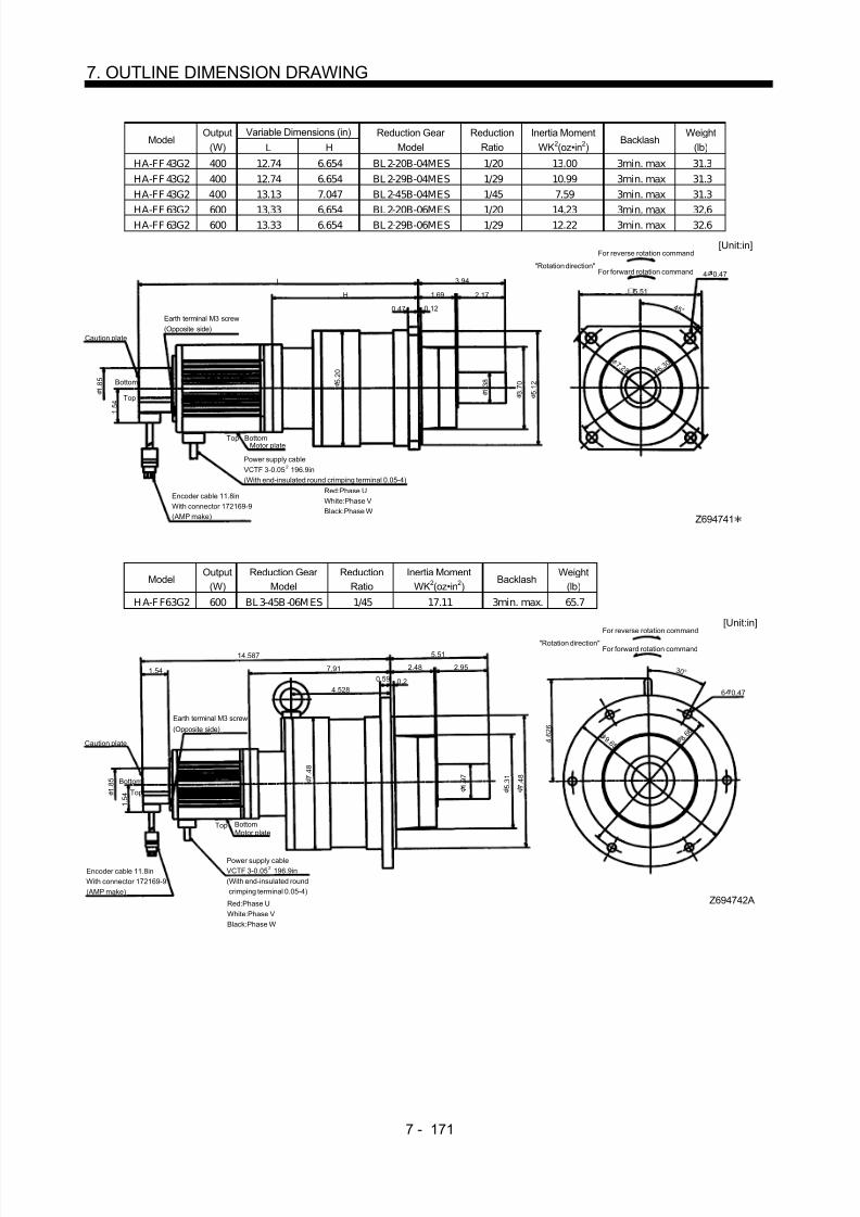
8/10/2019 Servo Motor - Instruction Manual SH(NA)-3181-D (03.00)
http://slidepdf.com/reader/full/servo-motor-instruction-manual-shna-3181-d-0300 250/368
7 - 171
7. OUTLINE DIMENSION DRAWING
Variable Dimensions (in)Model
Output(W) L H
Reduction Gear Model
ReductionRatio
Inertia MomentWK2(oz•in 2)
BacklashWeight
(lb)
HA-FF 43G2 400 12.74 6.654 BL 2-20B-04MES 1/20 13.00 3min. max 31.3HA-FF 43G2 400 12.74 6.654 BL 2-29B-04MES 1/29 10.99 3min. max 31.3HA-FF 43G2 400 13.13 7.047 BL 2-45B-04MES 1/45 7.59 3min. max 31.3
HA-FF 63G2 600 13.33 6.654 BL 2-20B-06MES 1/20 14.23 3min. max 32.6HA-FF 63G2 600 13.33 6.654 BL 2-29B-06MES 1/29 12.22 3min. max 32.6
Motor plate
Encoder cable 11.8inWith connector 172169-9(AMP make)
0.47
H
Top
Bottom
3.94
4 5 °
BottomTop
1 . 5 4
Caution plate
Earth terminal M3 screw(Opposite side)
0.12
2.171.69
L
[Unit:in]
"Rotation direction"For forward rotation command
For reverse rotation command
Power supply cableVCTF 3-0.05 196.9in(With end-insulated round crimping terminal 0.05-4)
2
Red:Phase UWhite:Phase VBlack:Phase W
1 . 8 5
5 . 2 0
1 . 3 8
3 . 7 0
5 . 1 2
7 .2 8 6. 3 0
4- 0.47
5.51
Z694741
ModelOutput
(W)Reduction Gear
ModelReduction
RatioInertia Moment
WK2(oz•in 2)Backlash
Weight(lb)
H A-F F63G2 600 BL 3-45B -06M ES 1/45 17.11 3min. max. 65.7
5.51
1.54
4 . 6 2 6
3 0 °
14.587
7.91
4.528
1.54 2.95
Earth terminal M3 screw
(Opposite side )
BottomTopMotor plate
Bottom
Top
0.59 0.2
Z694742A
Power supply cableVCTF 3-0.05 196.9in(With end-insulated roundcrimping terminal 0.05-4)
2
Red:Phase UWhite:Phase VBlack:Phase W
Encoder cable 11.8inWith connector 172169-9(AMP make)
[Unit:in]
"Rotation direction"For forward rotation command
For reverse rotation command
Caution plate
2.48
6- 0.47
8 . 6 6 9 .6 5
7 . 4 8
5 . 3 1
1 . 9 7
7 . 4 8
1
. 8 5

8/10/2019 Servo Motor - Instruction Manual SH(NA)-3181-D (03.00)
http://slidepdf.com/reader/full/servo-motor-instruction-manual-shna-3181-d-0300 251/368
7 - 172
7. OUTLINE DIMENSION DRAWING
(b) With electromagnetic brake
ModelOutput
(W)Braking Force
(oz•in)Reduction Gear
ModelReduction Ratio
Inertia MomentWK2(oz•in 2)
BacklashWeight
(lb)
HA-FF053BG2 50 55 BM2-05B-A5MES 1/5 0.70 3min. max. 5.7
1.18
4- 0.18
4 5 °
1.54
2 . 4 4
1 . 3 0 2 .
9 5
3.898
0.79
BottomTop
‰ºTop
Caution plate
0.24 0.08
9.45
Earth terminal M3
Bottom
2.91
1 . 5 4
1 . 8 5
Z694851
2
2
Earth terminal M3 screw
(Opposite side )
"Rotation direction"For forward rotation command
For reverse rotation command [Unit:in]
Brake leadVCTF 2-0.02 19.7in(With end-insulated round crimping terminal 0.05-4)
Motor plate
Power supply cableVCTF 3-0.05 19.7in(With end-insulated round crimping terminal 0.05-4)
Red:Phase UWhite:Phase VBlack:Phase W
Encoder cable 11.8inWith connector 172169-9(AMP make)
3 .5 0 3 . 0 7 0 . 3 9
Variable Dimensions (in)Model
Output(W) L
Braking Force(oz•in)
Reduction Gear Model
ReductionRatio
Inertia MomentWK2(oz•in 2)
BacklashWeight
(lb)
HA-FF053BG2 50 9.45 55 BM2-05B-A5MES 1/10 0.68 3 min. max. 5.7HA-FF053BG2 50 9.45 55 BM2-15B-A5MES 1/15 0.67 3 min. max. 5.7HA-FF13BG2 100 10.118 55 BM2-05B-01MES 1/5 0.87 3 min. max. 6.2
1.18
3 .5 0
4- 0.18
4 5 °
3. 0 7
1.54
2 . 4
4
1 . 3 0 2 .
9 5
3.898
0.79
BottomTop
Motor plate
Top
Caution plate
0.24 0.08
L
Earth terminal M3
Bottom
2.91
1 . 5 4
1 . 8 5
Z694812
Red:Phase UWhite:Phase VBlack:Phase W
2
2
"Rotation direction"For forward rotation command
For reverse rotation command[Unit:in]
Earth terminal M3 screw
(Opposite side)
Brake leadVCTF 2-0.02 19.7in(With end-insulated round crimping terminal 0.05-4)
Power supply cableVCTF 3-0.05 19.7in(With end-insulated round crimping terminal 0.05in-4)
Encoder cable 11.8inWith connector 172169-9(AMP make)
0 . 3 9

8/10/2019 Servo Motor - Instruction Manual SH(NA)-3181-D (03.00)
http://slidepdf.com/reader/full/servo-motor-instruction-manual-shna-3181-d-0300 252/368
7 - 173
7. OUTLINE DIMENSION DRAWING
Variable Dimensions (in)Model
Output(W) L
Braking Force(oz•in)
Reduction Gear Model
ReductionRatio
Inertia MomentWK2(oz•in 2)
BacklashWeight
(lb)
HA-FF053BG2 50 9.764 55 BM3-25B-A5MES 1/25 0.66 3 min. max. 7.1HA-FF13BG2 100 10.433 55 BM3-10B-01MES 1/10 0.87 3 min. max. 7.5HA-FF13BG2 100 10.433 55 BM3-15B-01MES 1/15 0.83 3 min. max. 7.5
1.38
4 .0 2
4 5 °
3. 5 4
1.54
2 . 9
9
1 . 6 1
3 . 4 2 5
4. 2 1 3
0.98
Motor plate
Top
Caution plate
0.31 0.08
L
Earth terminal M3
Bottom
3.43
1 . 5 4
1 . 8 5
Z694813
0.35
Red:Phase UWhite:Phase VBlack:Phase W
2
"Rotation direction"For forward rotation command
For reverse rotation command[Unit:in]
2Brake lead
VCTF 2-0.02 19.7in(With end-insulated round crimping terminal 0.05-4)
BottomTop
Power supply cableVCTF 3-0.05 19.7in(With end-insulated round crimping terminal 0.05-4)
Encoder cable 11.8inWith connector 172169-9(AMP make)
Earth terminal M3 screw
(Opposite side)
4- 0.22
4 5 °
0 . 5 5 1
ModelOutput
(W)Braking Force
(oz•in)Reduction Gear
ModelReduction
RatioInertia Moment
WK2(oz•in 2)Backlash
Weight(lb)
HA-FF13BG2 100 55 BM4-25B-01MES 1/25 1.68 3 min. max. 11.7
2.17
5 .5 1
0 . 8 6 6
4- 0.26
4 5 °
4. 8 0
1.54
3 . 9
4
2 . 4 0
4 . 6 5
5.472
1.57
BottomTopMotor plate
Caution plate
0.39 0.12
11.693
Bottom
4.65
1.54
1 . 8 5
Z694814
0.55
Top
"Rotation direction"For forward rotation command
For reverse rotation command[Unit:in]
Earth terminal M3 screw
(Opposite side)
2Brake leadVCTF 2-0.02 19.7in(With end-insulated round crimping terminal 0.05-4)
2Power supply cableVCTF 3-0.05 19.7in(With end-insulated round
crimping terminal 0.05-4)Red:Phase UWhite:Phase VBlack:Phase W
Encoder cable 11.8inWith connector 172169-9(AMP make)

8/10/2019 Servo Motor - Instruction Manual SH(NA)-3181-D (03.00)
http://slidepdf.com/reader/full/servo-motor-instruction-manual-shna-3181-d-0300 253/368
7 - 174
7. OUTLINE DIMENSION DRAWING
ModelOutput
(W)Braking Force
(oz•in)Reduction Gear
ModelReduction
RatioInertia Moment
WK2(oz•in 2)Backlash
Weight(lb)
HA-FF13BG2 100 55 BL 1-45B-01MES 1/45 1.63 3 min. max. 13.9
3.35
6 .1 0
0 . 9 8
4- 0.47
4 5 °
5. 1 2
1.54
3 . 9
4
2 . 7
6
4 . 0 1 6
5.945 1.57
Earth terminal M3 screw(Opposite side)
Bottom
Top
Motor plate
ã
Caution plate
1.69
0.12
Encoder cable 11.8inWith connector 172169-9(AMP make)
12.15
Bottom
4.72
1.54
1 . 8 5
Z694792
0.39
Top
Red:Phase UWhite:Phase VBlack:Phase W
"Rotation direction"
For forward rotation command
For reverse rotation command[Unit:in]
2Brake leadVCTF 2-0.02 19.7in(With end-insulated round crimping terminal 0.05-4)
2Power supply cable
VCTF 3-0.05 19.7in(With end-insulated roundcrimping terminal 0.05-4)
ModelOutput
(W)Braking Force
(oz•in)Reduction Gear
ModelReduction
RatioInertia Moment
WK2(oz•in 2)Backlash
Weight(lb)
HA-FF23BG2 200 170 BM3-05B-02MES 1/5 3.05 3 min. max. 9.7
1.38
4 .0 2
4- 0.22
4 5 °
3. 5 4
1.54
2 . 9
9
1 . 6
1
4.291
0.98Earth terminal M3 screw(Opposite side)
BottomTopMotor plate
Caution plate
0.31 0.08
10.91
Bottom
3.43
.
1 . 8 5
Z694815
0.35
Top
Red:Phase UWhite:Phase VBlack:Phase W
"Rotation direction"For forward rotation command
For reverse rotation command[Unit:in]
2Brake leadVCTF 2-0.02 19.7in(With end-insulated round crimping terminal 0.05-4)
2Power supply cableVCTF 3-0.05 19.7in(With end-insulated round crimping terminal 0.05-4)
Encoder cable 11.8inWith connector 172169-9
(AMP make)
0 . 5 5 1
3 . 4 2 5

8/10/2019 Servo Motor - Instruction Manual SH(NA)-3181-D (03.00)
http://slidepdf.com/reader/full/servo-motor-instruction-manual-shna-3181-d-0300 254/368

8/10/2019 Servo Motor - Instruction Manual SH(NA)-3181-D (03.00)
http://slidepdf.com/reader/full/servo-motor-instruction-manual-shna-3181-d-0300 255/368

8/10/2019 Servo Motor - Instruction Manual SH(NA)-3181-D (03.00)
http://slidepdf.com/reader/full/servo-motor-instruction-manual-shna-3181-d-0300 256/368
7 - 177
7. OUTLINE DIMENSION DRAWING
ModelOutput
(W)Braking Force
(oz•in)Reduction Gear
ModelReduction
RatioInertia Moment
WK2(oz•in 2)Backlash
Weight(lb)
HA-FF43BG2 400 326 BM4-05B-04M ES 1/5 8.98 3 min. max. 18.7
2.17
5 .5 1
0 . 8 6 6
4- 0.26
4 5 °
4. 8 0
1.54
3 . 9
4
2 . 4
0
4 . 6
5
5. 8 66
1. 5 7
0. 3 9 0. 1 2
13.41
4.65
1 . 5
4
1 . 8
5
Z694818
0. 5 5
Bottom
Top
BottomTopMotor plate
Encoder cable 11.8inWith connector 172169-9(AMP make)
Red:Phase UWhite:Phase VBlack:Phase W
Power supply cableVCTF 0.05 19.7in(With end-insulated roundcrimping terminal 0.05-4)
2
Brake leadVCTF 0.02 19.7in
(With end-insulated roundcrimping terminal 0.05-4)
2
[Unit:in]For forward
rotaation command
For reverse
rotation command
Earth terminal M3 screw
(Opposite side)
Caution plate
"Rotation direction"
Variable Dimensions (in)Model
Output(W) L H
Braking Force(oz•in)
Reduction Gear Model
ReductionRatio
Inertia MomentWK2(oz•in 2)
BacklashWeight
(lb)
HA-FF43BG2 400 13.09 5.551 326 BL 1-09B-04MES 1/9 8.43 3 min. max. 19.8HA-FF63BG2 600 13.29 5.157 326 BL 1-05B-06MES 1/5 10.16 3 min. max. 21.2HA-FF63BG2 600 13.68 5.551 326 BL 1-09B-06MES 1/9 9.66 3 min. max. 21.2
3.35
6 .1 0
0 . 9 8
4- 0.47
4 5 °
5. 1 2
1.54
3
. 9 4
2 . 7
6
4 . 0
1 6
H 1 .5 7
0. 3 9 0 .1 2
L 4.72
1 . 5
4
1
. 8 5
Z694795
1 .6 9
Bottom
Top
BottomTopMotor plate
Red:Phase UWhite:Phase VBlack:Phase W
Power supply cableVCTF 0.05 19.7in(With end-insulated roundcrimping terminal 0.05-4)
2
Encoder cable 11.8inWith connector 172169-9(AMP make)
Brake leadVCTF 0.02 19.7in(With end-insulated round crimping terminal 0.05-4)
2
[Unit:in]For forwardrotaation command
For reverse
rotation command
Earth terminal M3 screw
(Opposite side)Caution plate
"Rotation direction"

8/10/2019 Servo Motor - Instruction Manual SH(NA)-3181-D (03.00)
http://slidepdf.com/reader/full/servo-motor-instruction-manual-shna-3181-d-0300 257/368
7 - 178
7. OUTLINE DIMENSION DRAWING
Variable Dimensions (in)Model
Output(W) L H
Braking Force(oz•in)
Reduction Gear Model
ReductionRatio
Inertia MomentWK2(oz•in 2)
BacklashWeight
(lb)
HA-FF43BG2 400 360.5 6.654 326 BL2-20B-04MES 1/20 14.91 3 min. max. 33.1HA-FF43BG2 400 360.5 6.654 326 BL2-29B-04MES 1/29 12.90 3 min. max. 33.1HA-FF43BG2 400 370.5 7.047 326 BL2-45B-04MES 1/45 9.50 3 min. max. 33.1
HA-FF63BG2 600 375.5 6.654 326 BL2-20B-06MES 1/20 16.14 3 min. max. 34.4HA-FF63BG2 600 375.5 6.654 326 BL2-29B-06MES 1/29 14.13 3 min. max. 34.4
3.94
7 .2 8
1 . 3 8
4- 0.47
4 5 °
6. 3 0
5 . 1
2
3 . 7
0
5 . 2
0
H 2 .1 7
0. 4 7 0. 1 2
L 5.51
1 . 5
4
1 . 8
5
Z694796
1. 6 9
Bottom
Top
BottomTop
Motor plate
Encoder cable 11.8inWith connector 172169-9(AMP make)
Red:Phase UWhite:Phase VBlack:Phase W
Power supply cableVCTF 0.05 196.9in(With end-insulated roundcrimping terminal 0.05-4)
2
Brake leadVCTF 0.02 19.7in(With end-insulated round crimping terminal 0.05-4)
2
[Unit:in]
For forward
rotaation command
For reverse
rotation command
Earth terminal M3 screw(Opposite side)
Caution plate
"Rotation direction"
ModelOutput
(W)Braking Force
(oz•in)Reduction Gear
ModelReduction
RatioInertia Moment
WK2(oz•in 2)Backlash
Weight(lb)
HA-FF63BG2 600 326 BM3-45B-06MES 1/45 19.00 3 min. max. 74.3
5.51
9 .6 5
1 . 9 7
6- 0.47
3 0 °
8 . 6 6
1.54
7 . 4
8
4 . 6
2 6
5 . 3
1
7 .9 1 2. 9 5
0 .5 9 0 . 2
16.04
1 . 5
4
1 . 8
5
Z694797A
2. 4 8
4 . 5 28
BottomTop
BottomTop
Motor plate
Encoder cable 11.8inWith connector 172169-9(AMP make) Red:Phase U
White:Phase VBlack:Phase W
Power supply cableVCTF 0.05 196.9in(With end-insulated roundcrimping terminal 0.05-4)
2Brake leadVCTF 0.02 19.7in(With end-insulated round crimping terminal 0.05-4)
2
[Unit:in]
For forwardrotaation command
For reverse
rotation command
Earth terminal M3 screw(Opposite side)
Caution plate
"Rotation direction"
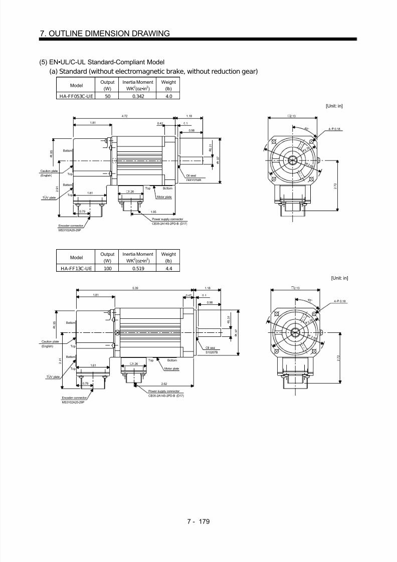
8/10/2019 Servo Motor - Instruction Manual SH(NA)-3181-D (03.00)
http://slidepdf.com/reader/full/servo-motor-instruction-manual-shna-3181-d-0300 258/368
7 - 179
7. OUTLINE DIMENSION DRAWING
(5) EN•UL/C-UL Standard-Compliant Model(a) Standard (without electromagnetic brake, without reduction gear)
ModelOutput
(W)Inertia Moment
WK2(oz•in 2)Weight
(lb)
HA-FF053C-UE 50 0.342 4.0[Unit: in]
TUV plate
Caution plate(English)
1.85
2.91
Bottom
Top
Bottom
Top1.61
0.79
1.26
1.95
Motor plate
Top Bottom
Oil sealGM10204B
4.72 1.18
0.42 0.1
0.98
0.31
1.97
1.81
Power supply connector CE05-2A14S-2PD-B (D17)
4- 0.184 5 °
2.13
2.72
Encoder connector MS3102A20-29P
2. 3 6
2 .6 8
ModelOutput
(W)Inertia Moment
WK2(oz•in 2)Weight
(lb)
HA-FF13C-UE 100 0.519 4.4
[Unit: in]
Caution plate
(English)
TUV plate
1.85
2.91
Bottom
Top
Bottom
Top1.61
0.79
Encoder connector MS3102A20-29P
1.81 0.47 0.1
5.39
0.98
1.18
0.31
1.97
Oil sealS10207B
Motor plate
Top Bottom
2.62
Power supply connector CE05-2A14S-2PD-B (D17)
1.26
4- 0.184 5 °
2.13
2.72
2. 3 6
2 .6 8

8/10/2019 Servo Motor - Instruction Manual SH(NA)-3181-D (03.00)
http://slidepdf.com/reader/full/servo-motor-instruction-manual-shna-3181-d-0300 259/368
7 - 180
7. OUTLINE DIMENSION DRAWING
Variable Dimensions (in)Model
Output(W) L KL
Inertia MomentWK2(oz•in 2)
Weight(lb)
HA-FF23C-UE 200 5.71 2.82 1.91 5.7HA-FF33C-UE 300 6.38 3.50 2.73 6.4
[Unit: in]
1.85
1.81
L 1.18
0.98
0.120.55
Caution plate(English)
TUV plate
Encoder connector MS3102A20-29P
0.79
1.61 1.26
Bottom
Top
Bottom
Top
Motor plate
KL0.10
0.16
0.16M4 threads, depth 0.59
0.43
Oil sealS15307B
A
A
0.63 0.16
2.76
Top Bottom
4- 0.224 5 °
2.99
3.11
Power supply connector CE05-2A14S-2PD-B (D17)
Section AA
3. 5 4
3 .9 4
2.91
Variable Dimensions (in)Model
Output(W) L KL
Inertia MomentWK2(oz•in 2)
Weight(lb)
HA-FF43C-UE 400 6.65 3.66 5.33 10.4HA-FF63C-UE 600 7.24 4.25 6.56 11.7
[Unit: in]
Caution plate
(English)
TUV plate
Bottom
Top
Bottom
Top
1.732
1.85
2.91
L 1.57
0.63 0.12
1.38
0.98 0.20
A
A
Oil sealS17308B
Motor plate 1.26
0.79
1.61
Encoder connector MS3102A20-29P Power supply connector
CE05-2A14S-2PD-B (D17)
KL
BottomTop
M5 threads, depth 0.79
Section AA
0.12
0.20
0.20
0.63
3.74
4- 0.35
4 5 °
3.94
3.58
1.85
E C
4 . 5 35 .3 1

8/10/2019 Servo Motor - Instruction Manual SH(NA)-3181-D (03.00)
http://slidepdf.com/reader/full/servo-motor-instruction-manual-shna-3181-d-0300 260/368
7 - 181
7. OUTLINE DIMENSION DRAWING
(b) With electromagnetic brake
ModelOutput
(W)Inertia Moment
WK2(oz•in 2)Braking Force
(oz•in)Weight
(lb)
HA-FF053CB-UE 50 0.437 55 4.6
[Unit: in]
Caution plate
TUV plate
Bottom
Top
Bottom
Top
C E 2.91
1.73
1.85
1.85
1.61
Encoder connector MS3102A20-29P
0.79
6.10 1.18
Motor plate(Opposite side)
BottomTop
0.47 0.1
0.98
Oil seal
GM10204B
0.31
1.97
3.31
Power supply connector
CE05-2A14S-2PD-B (D17)
Brake connector
MS3102E10SL-4P
1.26
1.40
4- 0.184 5 °
2.13
2.64
2 .6 8 2 . 3 6
1.10
ModelOutput
(W)Inertia Moment
WK2(oz•in 2)Braking Force
(oz•in)Weight
(lb)
HA-FF13CB-UE 100 0.615 55 5.1
[Unit: in]
Caution plate
TUV plate
Bottom
Top
C E 2.91
1.73
1.85
1.85
1.61
Encoder connector
MS3102A20-29P
0.79
6.77 1.18
0.43 0.1
0.98
Oil sealS10207B
0.31
1.97
3.98
Power supply connector CE05-2A14S-2PD-B (D17)
Brake connector
MS3102E10SL-4P
1.26
1.40
4- 0.184 5 °
2.13
2.64
Motor plate
Bottom
Top
BottomTop
2 .6 8 2 . 3 6
1.10

8/10/2019 Servo Motor - Instruction Manual SH(NA)-3181-D (03.00)
http://slidepdf.com/reader/full/servo-motor-instruction-manual-shna-3181-d-0300 261/368
7 - 182
7. OUTLINE DIMENSION DRAWING
Variable Dimensions (in)Model
Output(W) L KL
Braking Force(oz•in)
Inertia MomentWK2(oz•in 2)
Weight(lb)
HA-FF23CB-UE 200 7.17 4.29 2.64 7.7HA-FF33CB-UE 300 7.87 5.0
1703.46 8.4
[Unit: in]
Section AA
Caution plate(English)
TUV plate
Encoder connector MS3102A20-29P
0.79
2.91 1.61
1.81
1.85
1.26 1.10
Motor plate
Power supply connector CE05-2A14S-2PD-B (D17)
Brake connector MS3102E10SL-4P
1.18L
0.55 0.12
0.98
A
A
0.63 0.16
2.76
Oil sealS15307B
1.52
0.10
0.16
0.16
0.43
M4 threads, depth 0.59
KL
4- 0.224 5 °
2.99
3.11
BottomTop
3. 5 4
3 .9 4
Variable Dimensions (in)Model
Output(W) L KL
Braking Force(oz•in)
Inertia MomentWK2(oz•in 2)
Weight(lb)
HA-FF43CB-UE 400 8.11 5.12 7.24 12.8
HA-FF63CB-UE 600 8.70 5.71326
8.47 14.1[Unit: in]
Section AA
Caution plate
(English)
TUV plate
C E
1.85
2.91 1.61
0.791.732
Encoder connector MS3102A20-29P
Power supply connector CE05-2A14S-2PD-B (D17)
Motor plate
Brake connector MS3102E10SL-4P
KL
1.26 1.10
3.74
1.67
0.98
1.38
Top Bottom
A
A
0.20
0.63 0.12
1.57L
1.85
Oil sealS17308B
0.63
0.12
0.20
0.20
M5 threads, depth 0.79
4- 0.35
4 5 °
3.94
3.58
4 . 5 35 .3 1
Bottom
Top
Bottom
Top

8/10/2019 Servo Motor - Instruction Manual SH(NA)-3181-D (03.00)
http://slidepdf.com/reader/full/servo-motor-instruction-manual-shna-3181-d-0300 262/368
7 - 183
7. OUTLINE DIMENSION DRAWING
7.2.3 HC-SF•HC-SFS Series
(1) Standard (without electromagnetic brake, without reduction gear)Variable Dimensions (in)
ModelOutput(kW) L KL
Inertia MomentWK2(oz•in 2)
Weight(lb)
HC-SF52HC-SF53
HC-SFS52HC-SFS53
0.5 4.72 2.03 36.22 11.0
HC-SF102HC-SF103
HC-SFS102HC-SFS103
1.0 5.71 3.02 74.90 15.4
HC-SF81 HC-SFS81 0.85HC-SF152HC-SF153
HC-SFS152HC-SFS153
1.56.69 4.00 109.08 19.8
KL
0.77
W
V
U
A
B
CDE
FG
H
S30457B
MS3102A20-29P CE05-2A22-23P
3 . 2 1
1.56
L 2.165
0.470.12
1.97
0 . 9 5
4 . 3 3
1.61
4 . 3 7
6 .5 0
5. 7 1
5.12
4 5 °
Z694854
Bottom
Top
Encoder connector Power supply connector
Oil seal
Motor flange direction
Earth
Power supply connector layoutCE05-2A22-23P
Use hexagon socket head cap screw.
[Unit: in]
4- 0.35 mounting holeMotor plate
(Opposite side)
Bottom
Top
(BC11651 BC11757 BC11768 )
Variable Dimensions (in)Model Output(kW) L KL
Inertia MomentWK2(oz•in 2)
Weight(lb)
HC-SF121 HC-SFS121 1.2HC-SF202HC-SF203
HC-SFS202HC-SFS203
2.0 5.71 2.70 232.37 26.5
HC-SF201 HC-SFS201 2.0HC-SF352HC-SF353
HC-SFS352HC-SFS353
3.57.36 4.35 448.33 41.9
W
V
U
A
B
CDE
FG
KL
0.77
3 . 2 1
1.56
L 3.11
0.71 0.12
2.95
1.81
5 . 5 9
6.93
9 .0 6
7. 8 7
Z695393A
S40608B
MS3102A20-29P
CE05-2A24-10P
Encoder connector
Power supply connector
Oil seal
Motor flange direction
Power supply connector layoutCE05-2A24-10P
Motor plate
(Opposite side)
Bottom
Top
4- 0.53 mounting holeUse hexagon sockethead cap screw.
Earth
Bottom
Top
[Unit: in]
4 . 5
1 . 3 7 8
(BC11769 BC11652 BC11758 )

8/10/2019 Servo Motor - Instruction Manual SH(NA)-3181-D (03.00)
http://slidepdf.com/reader/full/servo-motor-instruction-manual-shna-3181-d-0300 263/368
7 - 184
7. OUTLINE DIMENSION DRAWING
ModelOutput(kW)
Inertia MomentWK2(oz•in 2)
Weight(lb)
HC-SF 301 HC-SFS301 3.0 552.212 50.7
W
V
U
AB
CDE
FG
5.157
0.77
3 . 2 1
1.56
8.189
0.71 0. 12
2.95
1.81
5 . 5 9
6.93
9 .0 6
7. 8 7
S40608B
MS3102A20-29P
CE05-2A24-10P
Encoder connector
Power supply connector
Oil seal
Motor flange direction
Power supply connector layoutCE05-2A24-10P
Motor plate(Opposite side)
Bottom
Top
4- 0.53 mountinghole Use hexagonsocket head capscrew.
Earth
Bottom
Top
[Unit: in]
BC10628(BC11769 )
3.11
4 5 °
1 . 3 7 8
4 . 5
ModelOutput(kW)
Inertia MomentWK2(oz•in 2)
Weight(lb)
HC-SF502 5.0 552.212 50.7
6.93
4 5 °
7. 8 7
4- 0.53 mountinghole Use hexagonsocket head capscrew.
5 . 5 9 1
9 .0 6
1.811
[Unit: in]
Power supply connector layoutCE05-2A24-10P
A
B
CDE
F G
UV
WPower supply connector CE05-2A24-10P
Encoder connector MS3102A20-29P
Motor plate
(Opposite side)
8.189
1.56 0.71 0.12
2.95
3.11
S40608BOil seal
TopBottom
3 . 2 1
0.77
Top
Bottom
1 . 3 7 8
4 . 5
Earth
5.177
BC10626A
Motor flange direction

8/10/2019 Servo Motor - Instruction Manual SH(NA)-3181-D (03.00)
http://slidepdf.com/reader/full/servo-motor-instruction-manual-shna-3181-d-0300 264/368
7 - 185
7. OUTLINE DIMENSION DRAWING
ModelOutput(kW)
Inertia MomentWK2(oz•in 2)
Weight(lb)
HC-SF702 7.0 874.791 70.5
6.93
4 5 °
7. 8 7
4- 0.53 mountinghole Use hexagonsocket head capscrew.
9 .0 6
2.283
[Unit: in]
Power supply connector layoutCE05-2A32-17P
A
BC
D
U
V
WPower supply connector CE05-2A32-17P
Encoder connector MS3102A20-29P
Motor plate
(Opposite side)
11.496
1.56 0.71 0.12
2.95
3.11
S40608BOil seal
TopBottom
3 . 2 1
0.77
Top
Bottom
1 . 3 7 8
4 . 5
Earth
8.287
BC10856
Motor flange direction
5 . 9 0 6
(2) With electromagnetic brakeVariable Dimensions (in)
ModelOutput(kW) L KL
Braking Force(oz•in)
Inertia MomentWK2(oz•in 2)
Weight(lb)
HC-SF52BHC-SF53B
HC-SFS52BHC-SFS53B
0.5 6.02 2.03 1204 45.52 16.535
HC-SF102BHC-SF103B
HC-SFS102BHC-SFS103B
1.0 7.01 3.02 1204 84.20 20.944
HC-SF81B HC-SFS81B 0.85HC-SF152BHC-SF153B
HC-SFS152BHC-SFS153B
1.5 7.99 4.00 1204 118.37 25.353
KL
0.77
W
VU
AB
CD
E
F
G
HMS3102A20-29P
CE05-2A22-23P
3 . 2 1
L 2.165
0.47 0.12
1.97
0 . 9 5
4 . 3 3
1.61
4 . 3 7
5.12
6 .5 0
5. 7 1
4 5 °
Z695005
Encoder connector
Power supply connector
Oil sealS30457B
Motor flange direction
Power supply connector layout(CE05-2A22-23P)
Use hexagon socket head cap screw.
4- 0.35 mounting hole
Motor plate(Opposite side)
Bottom
Top
Earth
[Unit: in]
Brake
(BC11653 BC11762 BC11775 )

8/10/2019 Servo Motor - Instruction Manual SH(NA)-3181-D (03.00)
http://slidepdf.com/reader/full/servo-motor-instruction-manual-shna-3181-d-0300 265/368
7 - 186
7. OUTLINE DIMENSION DRAWING
Variable Dimensions (in)Model
Output(kW) L KL
Braking Force(oz•in)
Inertia MomentWK2(oz•in 2)
Weight(lb)
HC-SF121B HC-SFS 121B 1.2HC-SF202BHC-SF203B
HC-SFS 202BHC-SFS 203B
2.0 7.60 2.70 6103 287.04 39.683
HC-SF201B HC-SFS 201B 2.0HC-SF352BHC-SF353B
HC-SFS 352BHC-SFS 353B
3.59.25 4.35 6103 503.01 55.115
KL
0.77
3 . 2 1
1.56
L 3.11
0 .71 0 .12
2.95
5 . 5 9
6.93
9 .0 6 7. 8 7
4 . 6 1
2.72
4 . 5
1 . 3 8
4 5 °
Z695319D
4- 0.53 mounting holeUse hexagon sockethead cap screw.
Bottom
Top
Power supply connector CE05-2A24-10P
[Unit: in]
Motor plate(Opposite side)
MS3102A20-29PEncoder connector
Brake connector MS3102A10SL-4P
S40608BOil seal
Bottom
Top
W
V
U
A
B
CDE
FG A B
Motor flange direction
Earth
Power supply connector layoutCE05-2A24-10P
Brake connector layoutMS3102A10SL-4P
Motor flange direction
Brake
(BC11654 BC11763 BC11776 )
Model Output(kW)
Braking Force(oz•in)
Inertia MomentWK2(oz•in 2)
Weight(lb)
HC-SF301B HC-SFS301B 3.0 6103 606.886 63.9
4 . 5
1 . 3 8
Encoder connector MS3102A20-29P
Motor plate(Oposite side)
5.1770.77
W
V
U
A
B
CD
E
FG
Power supplyconnector layoutCE05-2A24-10P
Motor flange drection
Oil sealS40608B 3 .
2 1
1.56
10.079 3.11
0.71 0.12
2.95
5 . 5 9 1
6.93
4- 0.53 mounting holeUse hexagon sockethead cap screw.
Bottom
Top
Bottom
Top
Brake connector MS3102A10SL-4P
9 .0 6
7. 8 7
4 . 6 1
2.72
Brake connectorlayoutMS3102A10SL-4P
A B
Motor flange drection
4 5 °
Brake
[Unit: in]
1.811EarthPower supplyconnector CE05-2A24-10P
BC10823(BC11776 )

8/10/2019 Servo Motor - Instruction Manual SH(NA)-3181-D (03.00)
http://slidepdf.com/reader/full/servo-motor-instruction-manual-shna-3181-d-0300 266/368
7 - 187
7. OUTLINE DIMENSION DRAWING
ModelOutput(kW)
Braking Force(oz•in)
Inertia MomentWK2(oz•in 2)
Weight(lb)
HC-SF502B 5.0 6103 606.886 63.9
4 . 5
1 . 3 8
Encoder connector MS3102A20-29P
Motor plate(Opposite side)
5.1770.77
EarthW
VU
A
BCDE
FG
Power supply connector layoutCE05-2A24-10P
Motor flange direction
Oil sealS40608B
Power supply connector
CE05-2A24-10P
3 . 2 1
1.56
10.079 3.11
0 .71 0 .12
2.95
5 . 5 9 1
6.93
4- 0.53 mounting hole
Use hexagon sockethead cap screw.
Bottom
Top
BottomTop
Brake connector MS3102A10SL-4P
9 .0 6
7. 8 7
4 . 6 1
2.72
4 5 °
[Unit: in]
BC10627A
1.811Brake connectorlayout
MS3102A10SL-4P
Brake
A B
Motor flange direction
ModelOutput(kW)
Braking Force(oz•in)
Inertia MomentWK2(oz•in 2)
Weight(lb)
HC-SF702B 7.0 6103 929.466 83.8
4 . 5
1 . 3 8
Encoder connector MS3102A20-29P
Motor plate(Opposite side)
8.2870.77
Earth
W
V
U
A
BC
DG
Power supply connectorlayoutCE05-2A32-17P
Motor flange direction
Oil sealS40608B
Power supply connector
CE05-2A32-17P
1.56
13.386 3.11
0 .71 0.12 6.93
4- 0.53 mounting holeUse hexagon socket
head cap screw.
Bottom
Top
BottomTop
Brake connector MS3102A10SL-4P
9 . 0
6
7. 8 7
2.72
4 5 °
[Unit: in]
BC10857
2.283Brake connectorlayout
MS3102A10SL-4P
Brake
A B
5 . 9 0 6
Motor flange direction
4 . 6 1
2.95
3 . 2 1

8/10/2019 Servo Motor - Instruction Manual SH(NA)-3181-D (03.00)
http://slidepdf.com/reader/full/servo-motor-instruction-manual-shna-3181-d-0300 267/368
7 - 188
7. OUTLINE DIMENSION DRAWING
(3) With reduction gear for general industrial machine (leg type)(a) Without electromagnetic brake
Variable Dimensions (in)Model
Output(kW)
ReductionRatio
Inertia MomentWK2(oz•in 2) L
Weight(lb)
HC-SF52G1H HC-SFS52G1H 0.5 1/35 41.01 13.31 61.7HC-SF52G1H HC-SFS52G1H 0.5 1/43 40.73 13.31 61.7HC-SF52G1H HC-SFS52G1H 0.5 1/59 40.60 13.31 61.7
HC-SF102G1H HC-SFS102G1H 1.0 1/6 91.85 14.30 66.1HC-SF102G1H HC-SFS102G1H 1.0 1/11 83.38 14.30 66.1HC-SF102G1H HC-SFS102G1H 1.0 1/17 81.47 14.30 66.1HC-SF102G1H HC-SFS102G1H 1.0 1/29 79.83 14.30 66.1HC-SF102G1H HC-SFS102G1H 1.0 1/35 79.69 14.30 66.1HC-SF152G1H HC-SFS152G1H 1.5 1/6 126.03 15.28 70.5HC-SF152G1H HC-SFS152G1H 1.5 1/11 117.55 15.28 70.5HC-SF152G1H HC-SFS152G1H 1.5 1/17 115.64 15.28 70.5
0.77
W
VU
L
2.175.16
AF GH
BEC
D
5.12
4.37
3.21
2.70
A
A
6.10
2.26 2.26
0.79
3.23
1.50
4- 0.55
0.39
0 . 3 2
0 . 2 0
9.06
3.74 3.74
2.17
0 . 6 0
4 . 7 2
9 . 9 2
Z695267B
MS3102A20-29P
CE05-2A22-23P
Bottom Top
Encoder connector
Power supply connector
Motor flange direction
Earth
Power supply connector layoutCE05-2A22-23P
[Unit: in]
Motor plate
[Side view of motor only]
Section A-A
"Rotation direction"
For reverserotation command
For forwardrotation command
(BC11798 )
Variable Dimensions (in)Model
Output(kW)
ReductionRatio
Inertia MomentWK2(oz•in 2) L
Weight(lb)
HC-SF52G1H HC-SFS52G1H 0.5 1/6 40.05 12.80 46.3HC-SF52G1H HC-SFS52G1H 0.5 1/11 38.00 12.80 46.3HC-SF52G1H HC-SFS52G1H 0.5 1/17 37.45 12.80 46.3HC-SF52G1H HC-SFS52G1H 0.5 1/29 37.04 12.80 46.3
W
VU
AFGH
BEC
D
L
4.37
5.12
8 . 6 2
8 . 1 5
3.21
0.77
2.70
4.76
4.33
1.38
A
A
1.77 1.77 2.36
0.59
5.32
0.32
0 . 2 8
0 . 1 6
1.10
3 . 9 4
0 . 4 7
2.952.95
1.58
7.09
4- 0.43
MS3102A20-29P
CE05-2A22-23P
Bot tom Top
Encoder connector
Power supply connector
Motor flange direction
Earth
Power supply connector layout(CE05-2A22-23P)
[Unit: in]
Motor plate
[Side view of motor only]
Section A-A
"Rotation direction"
For reverserotation command
For forwardrotation command
Z695356(BC11797 )
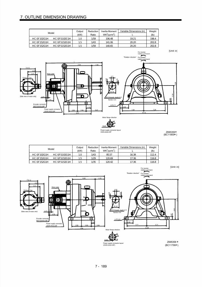
8/10/2019 Servo Motor - Instruction Manual SH(NA)-3181-D (03.00)
http://slidepdf.com/reader/full/servo-motor-instruction-manual-shna-3181-d-0300 268/368
7 - 189
7. OUTLINE DIMENSION DRAWING
Variable Dimensions (in)Model
Output(kW)
ReductionRatio
Inertia MomentWK2(oz•in 2) L
Weight(lb)
HC-SF102G1H HC-SFS102G1H 1.0 1/59 106.48 19.21 198.4HC-SF152G1H HC-SFS152G1H 1.5 1/43 141.06 20.20 202.8HC-SF152G1H HC-SFS152G1H 1.5 1/59 140.65 20.20 202.8
W
VU
AFGH
BEC
D
L
4.37
5.12
1 3 . 8 6
3.21
0.77
2.70
8.58 3.54
A
A
2.95 2.95 5.47
1.73
9.37
0.71
0 . 4 3
0 . 2 8
2.36
6 . 3 0
0 . 9 8
7.287.28
2.95
16.14
4- 0.71MS3102A20-29P
CE05-2A22-23P
Bottom Top
Encoder connector
Power supply connector
Motor flange direction
Earth
Power supply connector layoutCE05-2A22-23P
[Unit: in]
Motor plate
[Side view of motor only]
Section A-A
"Rotation direction"
For reverserotation command
For forwardrotation command
M10 threads, depth 0.71
Z695359(BC11800 )
Variable Dimensions (in)Model
Output
(kW)
Reduction
Ratio
Inertia Moment
WK2(oz•in
2) L
Weight
(lb)HC-SF102G1H HC-SFS102G1H 1.0 1/43 85.57 16.38 112.4HC-SF152G1H HC-SFS152G1H 1.5 1/29 120.69 17.36 116.8HC-SF152G1H HC-SFS152G1H 1.5 1/35 120.42 17.36 116.8
W
VU
AFGH
BEC
D
L
4.37
5.12
1 1 . 6 1
3.21
0.77
2.70
6.69 2.76
A
A
2.85 2.85 3.94
0.98
7.68
0.55
0 . 3 5
0 . 2 2
1.97
5 . 9 1
0 . 8 7
5.715.71
2.56
12.99
4- 0.43MS3102A20-29P
CE05-2A22-23P
Bottom Top
Encoder connector
Power supply connector
Motor flange direction
Earth
Power supply connector layout(CE05-2A22-23P)
[Unit: in]
Motor plate
[Side view of motor only]Section A-A
M10 threads, depth 0.71
"Rotation direction"
For reverserotation command
For forwardrotation command
Z695358(BC11799 )

8/10/2019 Servo Motor - Instruction Manual SH(NA)-3181-D (03.00)
http://slidepdf.com/reader/full/servo-motor-instruction-manual-shna-3181-d-0300 269/368
7 - 190
7. OUTLINE DIMENSION DRAWING
ModelOutput(kW)
ReductionRatio
Inertia MomentWK2(oz•in 2)
Weight(lb)
HC-SF 202G1H HC-SFS202G1H 2.0 1/6 249.32 77.2H C-SF 202G1H HC-SF S202G1H 2.0 1/11 241.11 77.2H C-SF 202G1H HC-SF S202G1H 2.0 1/17 238.93 77.2
5.59
15.0
5.16 2.17
1.50
6.93
3.21
A
A
0.77
3.01
9 . 9 2 0 .
2 0
4 . 7 2
Z695802B
0 . 6 0
2.17
3.74 3.74
9.06
4- 0.55
0 . 3 2
0.39
UV
WCD BE
AGF
3.23
0.79
2.262.26
6.10MS3102A20-29P
CE05-2A24-10P
Bottom Top
Encoder connector
Power supply connector
Motor flange direction
Earth
Power supply connector layoutCE05-2A24-10P
[Unit: in]
Motor plate
[Side view of motor only]
Section A-A
"Rotation direction"
For reverserotation command
For forwardrotation command
(BC11801 )
ModelOutput(kW)
ReductionRatio
Inertia MomentWK2(oz•in 2)
Weight(lb)
H C-SF 352G1H H C-SF S352G1H 3.5 1/6 492.62 132.3H C-SF 352G1H H C-SF S352G1H 3.5 1/11 471.21 132.3H C-SF 352G1H H C-SF S352G1H 3.5 1/17 464.73 132.3
5.59
18.62
6.60 2.76
1.97
6.93
3.21
A
A
0.77
3.01
1 1 . 5 0
0 . 2 2
1 0 . 4 3
Z695803A
5 . 9 1
2.56
5.71 5.71
12.99
4- 0.71
0 . 3 5
0.55
UV
WCD BE AGF
3.94
0.98
2.852.85
7.68
0 . 8 7
MS3102A20-29P
CE05-2A24-10P
Bottom Top
Encoder connector
Power supply connector Motor flange direction
Earth
Power supply connector layoutCE05-2A24-10P
[Unit: in]
Motor plate
[Side view of motor only]
"Rotation direction"
For reverserotation command
For forward
rotation command
Section A-A
M10 threads, depth 0.71
(BC11803 )

8/10/2019 Servo Motor - Instruction Manual SH(NA)-3181-D (03.00)
http://slidepdf.com/reader/full/servo-motor-instruction-manual-shna-3181-d-0300 270/368
7 - 191
7. OUTLINE DIMENSION DRAWING
Variable Dimensions (in)Model
Output(kW)
ReductionRatio
Inertia MomentWK2(oz•in 2) L
Weight(lb)
HC-SF202G1H HC-SFS202G1H 2.0 1/29 267.36 19.61 200.6HC-SF202G1H HC-SFS202G1H 2.0 1/35 265.72 19.61 200.6HC-SF202G1H HC-SFS202G1H 2.0 1/43 264.62 19.61 200.6
HC-SF202G1H HC-SFS202G1H 2.0 1/59 464.08 19.61 200.6HC-SF352G1H HC-SFS352G1H 3.5 1/29 483.32 21.26 216.1HC-SF352G1H HC-SFS352G1H 3.5 1/35 481.68 21.26 216.1
5.59
L
8.58 3.54
2.36
6.93
3.21
A
A
0.77
3.01
1 3 . 4 3
0 . 2 8
6 . 3 0
Z695804A
0 . 9 8
2.95
7.28 7.28
16.14
4- 0.71
0 . 4 3
0.71
UV
WCD BE AGF
5.47
1.73
2.952.95
9.37
1 1 . 8 1
MS3102A20-29P
CE05-2A24-10P
Bottom Top
Encoder connector
Power supply connector
Motor flange direction
Earth
Power supply connector layoutCE05-2A24-10P
[Unit: in]
[Side view of motor only]
"Rotation direction"
For reverserotation command
For forwardrotation command
Section A-A
M10 threads, depth 0.71
Motor plate
(BC11802 )
ModelOutput(kW)
ReductionRatio
Inertia MomentWK2(oz•in 2)
Weight(lb)
H C-SF 352G1H H C-SF S352G1H 3.5 1/43 582.28 306.4
H C-SF 352G1H H C-SF S352G1H 3.5 1/59 579.0 306.4
5.59
22.99
10.32 3.54
2.76
6.93
3.21
A
A
0.77
3.01
1 5 . 0
0 . 3 0
7 . 8 7
Z695805A
1 . 1 8
3.157.48 7.48
16.93
4- 0.87
0 . 4 7
0.79
UV
WCD BE AGF
0.921.18
5.415.41
13.19
1 3 . 3 9
MS3102A20-29P
CE05-2A24-10P
Bottom Top
Encoder connector
Power supply connector
Motor flange direction
Earth
Power supply connector layoutCE05-2A24-10P
[Unit: in]
Motor plate
[Side view of motor only]
"Rotation direction"
For reverserotation command
For forwardrotation command
Section A-A
M12 threads, depth 0.95
(BC11804 )
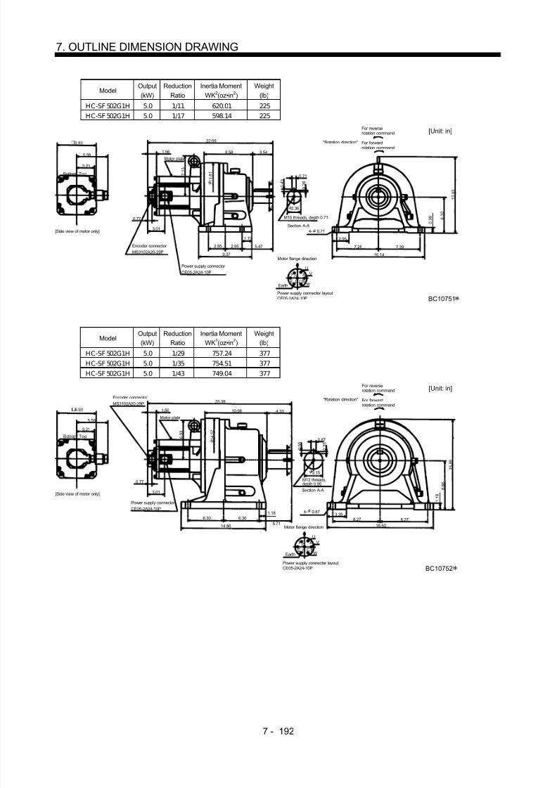
8/10/2019 Servo Motor - Instruction Manual SH(NA)-3181-D (03.00)
http://slidepdf.com/reader/full/servo-motor-instruction-manual-shna-3181-d-0300 271/368
7 - 192
7. OUTLINE DIMENSION DRAWING
ModelOutput(kW)
ReductionRatio
Inertia MomentWK2(oz•in 2)
Weight(lb)
HC-SF 502G1H 5.0 1/11 620.01 225HC-SF 502G1H 5.0 1/17 598.14 225
Power supply connector layoutCE05-2A24-10P
5.59
22.09
8.58 3.54
2.36
3.21
A
A
Motor plate
0.77
3.01
1 3 . 4 3 0 .
2 8
6 . 3 0
BC10751
0 . 9 8
2.95
7.28 7.28
16.14
4- 0.71
0 . 4 3
Motor flange direction
0.71
UV
WCD BE AGF
Earth
Section A-A
5.47
1.73
2.952.95
9.37
M10 threads, depth 0.71
1 1 . 8 1
Encoder connector MS3102A20-29P
Power supply connector CE05-2A24-10P
1.56
7 . 1 3
6.93
Bottom Top
[Side view of motor only]
[Unit: in]
"Rotation direction"
For reverserotation command
For forwardrotation command
ModelOutput(kW)
ReductionRatio
Inertia MomentWK2(oz•in 2)
Weight(lb)
HC-SF 502G1H 5.0 1/29 757.24 377HC-SF 502G1H 5.0 1/35 754.51 377HC-SF 502G1H 5.0 1/43 749.04 377
Power supply connector layoutCE05-2A24-10P
5.59
25.39
10.98 4.33
3.15
3.21
A
A
Motor plate
0.77
3.01
1 5 . 9 5
0 . 3 5
8 . 6 6
BC10752
1 . 1 8
3.358.27 8.27
18.50
4- 0.87
0 . 5 5
Motor flange direction
0.87
UV
WC
D BE
AGF
Earth
Section A-A
5.71
1.186.306.30
14.96
1 4 . 5 7
Encoder connector MS3102A20-29P
Power supply connector CE05-2A24-10P
1.56
6 . 9 3
6.93
Bottom Top
[Side view of motor only]
[Unit: in]
"Rotation direction"
For reverserotation command
For forwardrotation command
M12 threads,depth 0.95

8/10/2019 Servo Motor - Instruction Manual SH(NA)-3181-D (03.00)
http://slidepdf.com/reader/full/servo-motor-instruction-manual-shna-3181-d-0300 272/368
7 - 193
7. OUTLINE DIMENSION DRAWING
ModelOutput(kW)
ReductionRatio
Inertia MomentWK2(oz•in 2)
Weight(lb)
H C-SF 702G1H 7.0 1/11 1086.93 304H C-SF 702G1H 7.0 1/17 1038.82 304
Power supply connector layoutCE05-2A32-17P
5.91
27.13
10.32 3.54
2.76
3.21
A
A
Motor plate
0.77
3.21
1 5
0 . 3 0
7 . 8 7
BC10753
1 . 1 8
3.15
7.48 7.48
16.93
4- 0.87
0 . 4 7
Motor flange direction
0.79
UV
WCD
B
AEarth
Section A-A
4.92
1.18
5.415.41
13.19
Encoder connector
MS3102A20-29P
Power supplyconnector CE05-2A32-17P
7 . 1 3
1.56 6.93
Bottom Top
Side view of motor only]
[Unit: in]
"Rotation direction"
For reverserotation command
For forwardrotation command
M12 threads,depth 0.95
1 3 . 3 9
ModelOutput(kW)
ReductionRatio
Inertia MomentWK2(oz•in 2)
Weight(lb)
H C-SF 702G1H 7.0 1/29 1079.82 397H C-SF 702G1H 7.0 1/35 1077.09 397
Power supply connector layoutCE05-2A32-17P
5.91
28.70
10.98 4.33
3.15
3.21
A
A
Motor plate
0.77
3.21
1 5 . 9 5
0 . 3 5
8 . 6 6
BC10754
1 . 1 8
3.358.27 8.27
18.50
4- 0.87
0 . 5 5
Motor flange direction
0.87
U
VW
C
D
B
AEarth
Section A-A
5.71
1.186.306.30
14.96
1 4 . 5 7
Encoder connector
MS3102A20-29P
1.56
6 . 9 3
6.93
Bottom Top
[Side view of motor only]
[Unit: in]
"Rotation direction"
For reverserotation command
For forwardrotation command
M12 threads,depth 0.95Power supply
connector CE05-2A32-17P

8/10/2019 Servo Motor - Instruction Manual SH(NA)-3181-D (03.00)
http://slidepdf.com/reader/full/servo-motor-instruction-manual-shna-3181-d-0300 273/368

8/10/2019 Servo Motor - Instruction Manual SH(NA)-3181-D (03.00)
http://slidepdf.com/reader/full/servo-motor-instruction-manual-shna-3181-d-0300 274/368
7 - 195
7. OUTLINE DIMENSION DRAWING
(b) With electromagnetic brakeVariable Dimensions (in)
ModelOutput(kW)
ReductionRatio
Inertia MomentWK2(oz•in 2) L
Weight(lb)
Braking Force(oz•in)
HC-SF52BG1H HC-SFS52BG1H 0.5 1/35 50.3 14.61 72.8 1204HC-SF52BG1H HC-SFS52BG1H 0.5 1/43 50.03 14.61 72.8 1204HC-SF52BG1H HC-SFS52BG1H 0.5 1/59 49.89 14.61 72.8 1204
HC-SF102BG1H HC-SFS102BG1H 1.0 1/6 101.15 15.59 77.2 1204HC-SF102BG1H HC-SFS102BG1H 1.0 1/11 92.67 15.59 77.2 1204HC-SF102BG1H HC-SFS102BG1H 1.0 1/17 90.76 15.59 77.2 1204HC-SF102BG1H HC-SFS102BG1H 1.0 1/29 89.12 15.59 77.2 1204HC-SF102BG1H HC-SFS102BG1H 1.0 1/35 88.98 15.59 77.2 1204HC-SF152BG1H HC-SFS152BG1H 1.5 1/6 122.88 16.58 81.6 1204HC-SF152BG1H HC-SFS152BG1H 1.5 1/11 126.85 16.58 81.6 1204HC-SF152BG1H HC-SFS152BG1H 1.5 1/17 124.93 16.58 81.6 1204
0.77
W
VU
L
2.1655.16
AF G
HBECD
4.37
3.21
4.0
A
A
6.10
2.26 2.26 3.23
1.50
4- 0.55
0.39
0 . 3 2
0 . 2 0
9.06
3.74 3.74
2.165
0 . 6 0
4 . 7 2
9 . 9 2
MS3102A20-29PCE05-2A22-23P
Bottom Top
Encoder connector Power supply connector
Motor flange direction
Earth
Power supply connector layoutCE05-2A22-23P
[Unit: in]
Motor plate
[Side view of motor only]
"Rotation direction"
For reverserotation command
For forwardrotation command
Section A-A
Brake0.79
(BC11824 )
5.12
Z695365
Variable Dimensions (in)Model
Output(kW)
ReductionRatio
Inertia MomentWK2(oz•in 2) L
Weight(lb)
Braking Force(oz•in)
HC-SF52BG1H HC-SFS52BG1H 0.5 1/6 49.34 14.09 50.7 1204HC-SF52BG1H HC-SFS52BG1H 0.5 1/11 47.29 14.09 50.7 1204HC-SF52BG1H HC-SFS52BG1H 0.5 1/17 46.75 14.09 50.7 1204HC-SF52BG1H HC-SFS52BG1H 0.5 1/29 46.34 14.09 50.7 1204
W
VU
AF GHBECD
L
4.37
5.12
8 . 6 2
8 . 1 5
3.21
0.77
4.0
4.76
4.33
1.38
A
A
1.77 1.77 2.36
0.59
5.32
0.32
0 . 2 8
0 . 1 6
1.10
3 . 9 4
0 . 4 7
2.952.95
1.58
7.09
4- 0.43
Z695364
MS3102A20-29P
CE05-2A22-23P
Bottom Top
Encoder connector
Power supply connector
Motor flange direction
Earth
Power supply connector layout(CE05-2A22-23P)
[Unit: in]
Motor plate
[Side view of motor only]
"Rotation direction"
For reverserotation command
For forwardrotation command
Section A-A
Brake
(BC11823 )

8/10/2019 Servo Motor - Instruction Manual SH(NA)-3181-D (03.00)
http://slidepdf.com/reader/full/servo-motor-instruction-manual-shna-3181-d-0300 275/368
7 - 196
7. OUTLINE DIMENSION DRAWING
Variable Dimensions (in)Model
Output(kW)
ReductionRatio
Inertia MomentWK2(oz•in 2) L
Weight(lb)
Braking Force(oz•in)
HC-SF102BG1H HC-SFS102BG1H 1.0 1/59 115.77 20.51 202.8 1204HC-SF152BG1H HC-SFS152BG1H 1.5 1/43 150.36 21.50 207.2 1204HC-SF152BG1H HC-SFS152BG1H 1.5 1/59 149.94 21.50 207.2 1204
0.77
W
VU
L
3.548.58
AF G
HBECD
5.12
4.37
3.21
4.0
A
A
9.37
2.95 2.95
1.73
5.47
4- 0.71
16.14
7.28
0 . 9 8
2.95
6 . 3 0
1 3 . 8 6
7.28
Z695367
MS3102A20-29P
CE05-2A22-23P
Bottom Top
Encoder connector
Power supply connector
Motor flange direction
Earth
Power supply connector layoutCE05-2A22-23P
[Unit: in]
Motor plate
[Side view of motor only]
"Rotation direction"
For reverserotation command
For forwardrotation command
Brake
2.36
0.71
0 . 4 3
0 . 2 8
Section A-AM10 threads, depth 0.71
(BC11826 )
Variable Dimensions (in)Model
Output(kW)
ReductionRatio
Inertia MomentWK2(oz•in 2) L
Weight(lb)
Braking Force(oz•in)
HC-SF102BG1H HC-SFS102BG1H 1.0 1/43 94.86 17.68 116.8 1204HC-SF152BG1H HC-SFS152BG1H 1.5 1/29 129.99 18.66 121.3 1204HC-SF152BG1H HC-SFS152BG1H 1.5 1/35 129.72 18.66 121.3 1204
0.77
W
VU
L
2.766.69
AF GHBEC
D
5.12
4.37
3.21
4.0
A
A
7.68
2.85
0.98
3.94
1.97
4- 0.43
0.55
0 . 3 5
0 . 2 2
12.99
5.71
0 . 8 7
2.56
5 . 9 1
1 1 . 6 1
2.85 5.71
Z695366
MS3102A20-29P
CE05-2A22-23P
Bottom Top
Encoder connector
Power supply connector
Motor flange direction
Earth
Power supply connector layoutCE05-2A22-23P
[Unit: in]
Motor plate
[Side view of motor only]
"Rotation direction"
For reverserotation command
For forwardrotation command
Brake
Section A-AM10 threads, depth 0.71
(BC11825 )

8/10/2019 Servo Motor - Instruction Manual SH(NA)-3181-D (03.00)
http://slidepdf.com/reader/full/servo-motor-instruction-manual-shna-3181-d-0300 276/368
7 - 197
7. OUTLINE DIMENSION DRAWING
ModelOutput(kW)
ReductionRatio
Inertia MomentWK2(oz•in 2)
Weight(lb)
Braking Force(oz•in)
HC-SF 202BG1H HC-SFS202BG1H 2.0 1/6 303.99 90.4 6103H C-SF 202BG1H H C-SF S202BG1H 2.0 1/11 295.79 90.4 6103H C-SF 202BG1H H C-SF S202BG1H 2.0 1/17 293.60 90.4 6103
Z695852A
0.77
W
VU
16.89
5.16
AFG
BECD
6.93
5.59
4.61
2.72
A
A
4.90
2.26
6.10
1.50
0.39
0 . 3 2
0 . 2 0
2.165
0 . 6 0
4 . 7 2
1 0 . 3 2
3.74
3.21
A B
2.165
4- 0.55
3.74
9.06
2.26 3.23
MS3102A20-29P
CE05-2A24-10P
Bottom Top
Encoder connector
Power supply connector
Motor flange direction
Earth
Power supply connector layoutCE05-2A24-10P
[Unit: in]
Motor plate
[Side view of motor only]
"Rotation direction"
For reverserotation command
For forwardrotation command
Motor flange direction
Brake connector MS3102A10SL-4P
Brake connector layoutMS3102A10SL-4P
Brake
Section A-A
0.79
(BC11827 )
ModelOutput(kW)
ReductionRatio
Inertia MomentWK2(oz•in 2)
Weight(lb)
Braking Force(oz•in)
H C-SF 352BG1H H C-SF S352BG1H 3.5 1/6 547.29 145.5 6103H C-SF 352BG1H HC-SF S352BG1H 3.5 1/11 525.97 145.5 6103H C-SF 352BG1H HC-SF S352BG1H 3.5 1/17 519.41 145.5 6103
Z695853A
0.77
W
VU
20.51
6.69
AFGBE
CD
6.93
5.594.61
2.72
A
A
4.90
2.85
7.68
1.97
0.55
0 . 3 5 0 .
2 2
2.56
0 . 8 7
5 . 9 1
1 0 . 4 3
5.71
3.21
AB
2.76
4- 0.71
5.71
12.99
2.85 3.94
1 1 . 5 0
MS3102A20-29P
CE05-2A24-10P
Bottom Top
Encoder connector
Power supply connector
Motor flange direction
Earth
Power supply connector layoutCE05-2A24-10P
[Unit: in]
Motor plate
[Side view of motor only]
"Rotation direction"
For reverserotation command
For forwardrotation command
Brake connector MS3102A10SL-4P
Brake connector layoutMS3102A10SL-4P
Brake
Motor flange direction
Section A-A
M10 threads, depth 0.71
0.98
(BC11829 )

8/10/2019 Servo Motor - Instruction Manual SH(NA)-3181-D (03.00)
http://slidepdf.com/reader/full/servo-motor-instruction-manual-shna-3181-d-0300 277/368
7 - 198
7. OUTLINE DIMENSION DRAWING
Variable Dimensions (in)Model
Output(kW)
ReductionRatio
Inertia MomentWK2(oz•in 2) L
Weight(lb)
Braking Force(oz•in)
HC-SF202BG1H HC-SFS202BG1H 2.0 1/29 322.03 21.50 213.8 6103HC-SF202BG1H HC-SFS202BG1H 2.0 1/35 320.39 21.50 213.8 6103HC-SF202BG1H HC-SFS202BG1H 2.0 1/43 319.30 21.50 213.8 6103
HC-SF202BG1H HC-SFS202BG1H 2.0 1/59 318.75 21.50 213.8 6103HC-SF352BG1H HC-SFS352BG1H 3.5 1/29 538.8 23.15 229.3 6103HC-SF352BG1H HC-SFS352BG1H 3.5 1/35 536.36 23.15 229.3 6103
Z695854A
0.77
W
VU
L
8.58
AFG
BECD
6.93
5.59
4.61
2.72 A
A
4.90
9.37
2.36
0 . 4 3
0 . 2 8
2.951.73
6 . 3 0
7.28
3.21
AB
16.14
5.47
0.71
1 3 . 4 3
3.54
4- 0.71
7.282.95 2.95
1 1 . 8 1MS3102A20-29P
CE05-2A24-10P
Bottom TopEncoder connector
Power supply connector
Motor flange direction
Earth
Power supply connector layoutCE05-2A24-10P
[Unit: in]
Motor plate
[Side view of motor only]
"Rotation direction"
For reverserotation command
For forwardrotation command
Brake connector MS3102A10SL-4P
Brake connector layoutMS3102A10SL-4P
Brake
Motor flange direction
Section A-AM10 threads, depth 0.71
0 . 9 8
(BC11828 )
ModelOutput(kW)
ReductionRatio
Inertia MomentWK2(oz•in 2)
Weight(lb)
Braking Force(oz•in)
H C-SF 352BG1H HC-SF S352BG1H 3.5 1/43 636.96 319.7 6103
H C-SF 352BG1H HC-SF S352BG1H 3.5 1/59 633.68 319.7 6103
Z695855A
0.77
W
VU
24.88
10.32
AF GBE
CD
6.93
5.59
4.61
2.72 A
A
4.90
13.19
2.76
0 . 4 7
0 . 3 0
3.15
7 . 8 7
7.48
3.21
AB 16.934.92
0.79
1 5 . 0
3.54
4- 0.87
7.485.41 5.41
Section A-AM12 threads, depth 0.95
MS3102A20-29P
CE05-2A24-10P
Bottom Top
Encoder connector
Power supply connector
Motor flange direction
Earth
Power supply connector layoutCE05-2A24-10P
[Unit: in]
Motor plate
[Side view of motor only]
"Rotation direction"
For reverserotation command
For forwardrotation commandBrake connector
MS3102A10SL-4P
Brake connector layoutMS3102A10SL-4P
Brake
Motor flange direction
1 . 1 8
1. 18
(BC11830 )

8/10/2019 Servo Motor - Instruction Manual SH(NA)-3181-D (03.00)
http://slidepdf.com/reader/full/servo-motor-instruction-manual-shna-3181-d-0300 278/368
7 - 199
7. OUTLINE DIMENSION DRAWING
ModelOutput(kW)
ReductionRatio
Inertia MomentWK2(oz•in 2)
Weight(lb)
H C-SF 502BG1H 5.0 1/11 674.68 238.1H C-SF 502BG1H 5.0 1/17 652.81 238.1
Power supply connector layoutCE05-2A24-10P
5.59
23.98
8.58 3.54
2.36
4.61
A
A
Motor plate
0.77
2.72
1 3 . 4 3
0 . 2 8
6 . 3 0
BC11028
0 . 9 8
2.95
7.28 7.28
16.14
4- 0.71
0 . 4 3
Motor flange direction
0.71
UV
WCD BE AGF
Earth
Section A-A
5.47
1.73
2.952.95
9.37
M10 threads, depth 0.71
1 1 . 8 1
Encoder connector MS3102A20-29P
Power supply connector CE05-2A24-10P
1.56
7 . 1 33.21
Brake connector layoutMS3102A10SL-4P
Motor flange direction
B ABrake
4.90
Brake connector MS3102A10SL-4P
6.93
Bottom Top
[Side view of motor only]
[Unit: in]
"Rotation direction"
For reverserotation command
For forwardrotation command
ModelOutput(kW)
ReductionRatio
Inertia MomentWK2(oz•in 2)
Weight(lb)
H C-SF 502BG1H 5.0 1/29 811.92 390.2H C-SF 502BG1H 5.0 1/35 809.18 390.2H C-SF 502BG1H 5.0 1/43 803.71 390.2
5.59
27.28
10.98 4.33
3.15
4.61
A
A
Motor plate
0.77
2.72
1 5 . 9 5
0 . 3 5
8 . 6 6
BC11029
1 . 1 8
3.358.27 8.27
18.50
4- 0.87
0 . 5 5 0.87
Power supply connector layoutCE05-2A24-10P
Motor flange direction
U
V
WCD BE
AGF
Earth
Section A-A
5.711.18
6.306.30
14.96
M12 threads, depth 0.95
1 4 . 5 7
Encoder connector
MS3102A20-29P
Power supplyconnector CE05-2A24-10P
1.56
6 . 9 33.21
Brake connector layoutMS3102A10SL-4P
Motor flange direction
B A
Brake
4.90
Brake connector MS3102A10SL-4P
6.93
Bottom Top
[Side view of motor only]
[Unit: in]
"Rotation direction"
For reverserotation command
For forwardrotation command
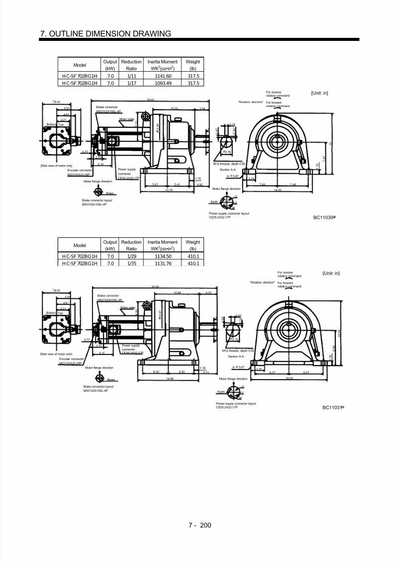
8/10/2019 Servo Motor - Instruction Manual SH(NA)-3181-D (03.00)
http://slidepdf.com/reader/full/servo-motor-instruction-manual-shna-3181-d-0300 279/368
7 - 200
7. OUTLINE DIMENSION DRAWING
ModelOutput(kW)
ReductionRatio
Inertia MomentWK2(oz•in 2)
Weight(lb)
H C-SF 702BG1H 7.0 1/11 1141.60 317.5H C-SF 702BG1H 7.0 1/17 1093.49 317.5
Power supply connector layoutCE05-2A32-17P
5.91
29.02
10.32 3.54
2.76
4.61
A
A
Motor plate
0.77
2.72
1 5
0 . 3 0
7 . 8 7
BC11030
1 . 1 8
3.15
7.48 7.48
16.93
4- 0.87
0 . 4 7
Motor flange direction
0.79
U
V
WCD
B
AEarth
Section A-A
4.92
1.18
5.415.41
13.19
M12 threads, depth 0.95
1 3 . 3 9
Encoder connector MS3102A20-29P
Power supplyconnector CE05-2A32-17P
7 . 1 33.21
Brake connector layoutMS3102A10SL-4P
Motor flange direction
B ABrake
5.10
Brake connector MS3102A10SL-4P
6.93
Bottom Top
[Side view of motor only]
[Unit: in]
"Rotation direction"
For reverserotation command
For forwardrotation command
ModelOutput(kW)
ReductionRatio
Inertia MomentWK2(oz•in 2)
Weight(lb)
H C-SF 702BG1H 7.0 1/29 1134.50 410.1H C-SF 702BG1H 7.0 1/35 1131.76 410.1
Power supply connector layoutCE05-2A32-17P
5.91
30.59
10.98 4.33
3.15
4.61
A
A
Motor plate
0.77
2.72
1 5 . 9 5
0 . 3 5
8 . 6 6
BC11031
1 . 1 8
3.358.27 8.27
18.50
4- 0.87
0 . 5 5
Motor flange direction
0.87
U
V
WCD
B
AEarth
Section A-A
5.711.18
6.306.30
14.96
M12 threads, depth 0.95
1 4 . 5 7
Encoder connector MS3102A20-29P
6 . 9 33.21
Brake connector layoutMS3102A10SL-4P
Motor flange direction
B ABrake
5.10
Brake connector MS3102A10SL-4P
6.93
Bottom Top
[Side view of motor only]
[Unit: in]
"Rotation direction"
For reverserotation command
For forwardrotation command
Power supplyconnector CE05-2A32-17P

8/10/2019 Servo Motor - Instruction Manual SH(NA)-3181-D (03.00)
http://slidepdf.com/reader/full/servo-motor-instruction-manual-shna-3181-d-0300 280/368
7 - 201
7. OUTLINE DIMENSION DRAWING
ModelOutput(kW)
ReductionRatio
Inertia MomentWK2(oz•in 2)
Weight(lb)
H C-SF 702BG1H 7.0 1/43 1458.71 588.6
5.91
34.17
12.99 5.32
3.74
4.61
A
A
Motor plate
0.77
2.72
1 8 . 3 1
0 . 3 5
9 . 8 4
BC11032
1 . 3 8
3.54
9.45 9.4520.87
4- 1.02
0 . 5 5
0.98
Power supply connector layoutCE05-2A32-17P
Motor flange direction
U
V
WCD
B
AEarth
Section A-A
6.69
1.18
7.487.4817.32
M20 threads, depth 1.34
1 6 . 9 3
Encoder connector MS3102A20-29P
8 . 2 73.21
Brake connector layoutMS3102A10SL-4P
Motor flange direction
B ABrake
5.10
Brake connector MS3102A10SL-4P
6.93
Bottom Top
[Side view of motor only]
[Unit: in]
"Rotation direction"
For reverserotation command
For forward
rotation command
Power supplyconnector CE05-2A32-17P

8/10/2019 Servo Motor - Instruction Manual SH(NA)-3181-D (03.00)
http://slidepdf.com/reader/full/servo-motor-instruction-manual-shna-3181-d-0300 281/368
7 - 202
7. OUTLINE DIMENSION DRAWING
(4) With reduction gear for general industrial machine (flange type)(a) Without electromagnetic brake
Variable Dimensions (in)Model
Output(kW)
ReductionRatio
Inertia MomentWK2(oz•in 2) L
Weight(lb)
HC-SF52G1 HC-SFS52G1 0.5 1/35 41.01 10.59 59.5HC-SF52G1 HC-SFS52G1 0.5 1/43 40.73 10.59 59.5HC-SF52G1 HC-SFS52G1 0.5 1/59 40.60 10.59 59.5
HC-SF102G1 HC-SFS102G1 1.0 1/6 91.85 11.58 63.9HC-SF102G1 HC-SFS102G1 1.0 1/11 83.38 11.58 63.9HC-SF102G1 HC-SFS102G1 1.0 1/17 81.47 11.58 63.9HC-SF102G1 HC-SFS102G1 1.0 1/29 79.83 11.58 63.9HC-SF102G1 HC-SFS102G1 1.0 1/35 79.69 11.58 63.9HC-SF152G1 HC-SFS152G1 1.5 1/6 126.03 12.56 68.3HC-SF152G1 HC-SFS152G1 1.5 1/11 117.55 12.56 68.3HC-SF152G1 HC-SFS152G1 1.5 1/17 115.64 12.56 68.3
0.77
W
VU
L 2.724.61
AF GH
BECD
5.12
4.37
3.21
2.70
A
A
1.50
0.39
0 . 3 2
0 . 2 0
5 . 2 0
0.51 0.16
2.17
5 . 5 1
8 . 2 7
6- 0.43
3 0 °
Z695270C
MS3102A20-29P CE05-2A22-23P
Bottom Top
Encoder connector Power supply connector Motor flange direction
Earth
Power supply connector layoutCE05-2A22-23P
[Unit: in]
Motor plate
[Side view of motor only]
"Rotation direction"
For reverserotation command
For forwardrotation command
Section A-A
7 .
0 9
(BC11811 )
Variable Dimensions (in)Model
Output(kW)
ReductionRatio
Inertia MomentWK2(oz•in 2) L
Weight(lb)
HC-SF52G1 HC-SFS52G1 0.5 1/6 40.05 10.91 40.8HC-SF52G1 HC-SFS52G1 0.5 1/11 38.13 10.91 40.8HC-SF52G1 HC-SFS52G1 0.5 1/17 37.45 10.91 40.8HC-SF52G1 HC-SFS52G1 0.5 1/29 37.04 10.91 40.8
W
VU
AFGH
BECD
L
4.37
5.12
4 . 6 9
4 . 2 1
3.21
0.77
2.70
4.25 1.38
1.89
A
A
0.32
4 . 3 3
0 . 1 6
1.10
2.44
0.35
5 . 9 1
6 . 3 0
0 . 2 8
5. 2 8
4 5 °
4- 0.43
Z695360
MS3102A20-29P
CE05-2A22-23P
Bottom Top
Encoder connector
Power supply connector
Motor flange direction
Earth
Power supply connector layout(CE05-2A22-23P)
[Unit: in]
Motor plate
[Side view of motor only]
"Rotation direction"
For reverserotation command
For forwardrotation command
Section A-A
0.12
(BC11810 )

8/10/2019 Servo Motor - Instruction Manual SH(NA)-3181-D (03.00)
http://slidepdf.com/reader/full/servo-motor-instruction-manual-shna-3181-d-0300 282/368
7 - 203
7. OUTLINE DIMENSION DRAWING
Variable Dimensions (in)Model
Output(kW)
ReductionRatio
Inertia MomentWK2(oz•in 2) L
Weight(lb)
HC-SF102G1 HC-SFS102G1 1.0 1/59 106.48 13.35 183.0HC-SF152G1 HC-SFS102G1 1.5 1/43 141.06 16.69 187.4HC-SF152G1 HC-SFS102G1 1.5 1/59 140.65 16.69 187.4
W
VU
AFGH
BECD
L
4.31
5.12
7 . 5 63.21
0.772.70
8.62
3.50
A
A
0.71
0 . 4 3
2.36
0.79 0.16
1 1 . 8
1 0 . 6 3
1 3 . 3 9
0 . 2 8
6- 0.438.98
6 0 °
Z695363
MS3102A20-29P
CE05-2A22-23P
Bottom Top
Encoder connector
Power supply connector
Motor flange direction
Earth
Power supply connector layoutCE05-2A22-23P
[Unit: in]
Motor plate
[Side view of motor only]
"Rotation direction"
For reverserotation command
For forwardrotation command
Section A-A
M10 threads, depth 0.71
1 2
. 2 1
(BC11813 )
Variable Dimensions (in)Model
Output(kW)
ReductionRatio
Inertia MomentWK2(oz•in 2) L
Weight(lb)
HG-SF102G1 HG-SFS102G1 1.0 1/43 85.57 13.39 105.8
HC-SF152G1 HC-SFS152G1 1.5 1/29 120.69 14.37 110.2HC-SF152G1 HC-SFS152G1 1.5 1/35 120.42 14.37 110.2
W
VU
AFGH
BECD
L
4.37
5.12
5 . 7 1
3.21
0.77
2.70
6.46
2.99
A
A
0.55
0 . 3 5
1.97
0.59 0.16
9 . 0 6
7 . 8 7
2.76
1 0 . 2 4
0 . 2 2
9
. 0 6
6- 0.437.21
6 0 °
Z695362
MS3102A20-29P
CE05-2A22-23P
Bottom Top
Encoder connector
Power supply connector
Motor flange direction
Earth
Power supply connector layout(CE05-2A22-23P)
[Unit: in]
Motor plate
[Side view of motor only]
"Rotation direction"
For reverserotation command
For forwardrotation command
Section A-A
M10 threads, depth 0.71
(BC11812 )

8/10/2019 Servo Motor - Instruction Manual SH(NA)-3181-D (03.00)
http://slidepdf.com/reader/full/servo-motor-instruction-manual-shna-3181-d-0300 283/368
7 - 204
7. OUTLINE DIMENSION DRAWING
ModelOutput(kW)
ReductionRatio
Inertia MomentWK2(oz•in 2)
Weight(lb)
HC-SF 202G1 HC-SF S202G1 2.0 1/6 249.32 75.0H C-SF 202G1 H C-SF S202G1 2.0 1/11 241.11 75.0H C-SF 202G1 H C-SF S202G1 2.0 1/17 238.93 75.0
5.59
12.28 2.72
2.17
6.93
3.21
A
A
3.01
5 . 5 9
0 . 2 0
Z695806A
3 0 °
1.50
0 . 3 2
0.39
UV
WCD BE AGF
4.61
8 . 0 3
5 . 5 1
8 . 2 7
0.160.51
0.77
6- 0.43
MS3102A20-29P
CE05-2A24-10P
Bottom Top
Encoder connector
Power supply connector
Motor flange direction
Earth
Power supply connector layoutCE05-2A24-10P
[Unit: in]
Motor plate
[Side view of motor only]
"Rotation direction"
For reverserotation command
For forwardrotation command
Section A-A
7 .
0 9
(BC11814 )
ModelOutput(kW)
ReductionRatio
Inertia MomentWK2(oz•in 2)
Weight(lb)
H C-SF 352G1 HC-SF S352G1 3.5 1/6 492.62 125.7H C-SF 352G1 H C-SF S352G1 3.5 1/11 471.29 125.7H C-SF 352G1 H C-SF S352G1 3.5 1/17 464.73 125.7
5.59
15.63 2.99
2.76
6.93
3.21
A
A
3.01
5 . 5 9
0 . 2 2
Z695807A
6 0 °
1.97
0 . 3 5
8.23
UV
WCD BE AGF
6.46
9 . 0 6
7 . 8 7
1 0 . 2 4
0.160.59
0.77
6- 0.43
0.55
MS3102A20-29P CE05-2A24-10P
Bottom Top
Encoder connector Power supply connector Motor flange direction
Earth
Power supply connector layoutCE05-2A24-10P
[Unit: in]
Motor plate
[Side view of motor only]
"Rotation direction"
For reverserotation command
For forwardrotation command
Section A-AM10 threads, depth 0.71
9 .
0 6
(BC11816 )
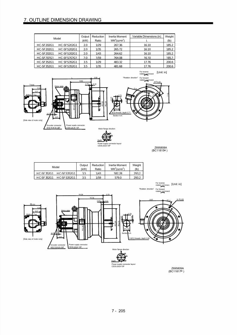
8/10/2019 Servo Motor - Instruction Manual SH(NA)-3181-D (03.00)
http://slidepdf.com/reader/full/servo-motor-instruction-manual-shna-3181-d-0300 284/368
7 - 205
7. OUTLINE DIMENSION DRAWING
Variable Dimensions (in)Model
Output(kW)
ReductionRatio
Inertia MomentWK2(oz•in 2) L
Weight(lb)
HC-SF202G1 HC-SFS202G1 2.0 1/29 267.36 16.10 185.2HC-SF202G1 HC-SFS202G1 2.0 1/35 265.72 16.10 185.2HC-SF202G1 HC-SFS202G1 2.0 1/43 264.62 16.10 185.2
HC-SF202G1 HC-SFS202G1 2.0 1/59 264.08 16.10 185.2HC-SF352G1 HC-SFS352G1 3.5 1/29 483.32 17.76 200.6HC-SF352G1 HC-SFS352G1 3.5 1/35 481.68 17.76 200.6
5.59
L 3.50
0.16 6.93
3.21
A
A
3.01
7 . 1 3
0 . 2 8
Z695808A
6 0 °
2.36
0 . 4 3
0.71
UV
WCD BE AGF
8.62
1 1 . 8 1
1 0 . 6 3
1 3 . 3 9
4
0.79
0.77
6- 0.43
8 .9 8
Section A-A
M10 threads, depth 0.71
MS3102A20-29P CE05-2A24-10P
Bottom Top
Encoder connector Power supply connector
Motor flange direction
Earth
Power supply connector layoutCE05-2A24-10P
[Unit: in]
Motor plate
[Side view of motor only]
"Rotation direction"
For reverserotation command
For forwardrotation command
1 2 .
2 1
(BC11815 )
1 5 °
ModelOutput(kW)
ReductionRatio
Inertia MomentWK2(oz•in 2)
Weight(lb)
H C-SF 352G1 H C-SF S352G1 3.5 1/43 582.28 293.2H C-SF 352G1 H C-SF S352G1 3.5 1/59 579.0 293.2
5.59
3.70
6.93
3.21
A
A
3.01
0 . 4 7
Z695809A
2 2 .5 °
0 . 3 0
0.79
UV
WCD BE AGF
19.29
1 3 . 3 9
1 2 . 4 4
1 5 . 7 5
0.200.87
0.77
8- 0.559.5710.16
MS3102A20-29P CE05-2A24-10P
Bottom Top
Encoder connector Power supply connector
Motor flange direction
Earth
Power supply connector layoutCE05-2A24-10P
[Unit: in]
Motor plate
[Side view of motor only]
"Rotation direction"
For reverserotation command
For forwardrotation command
1-M12 threads, depth 0.95
Section A-A 1 4
. 1 72.76
(BC11817 )

8/10/2019 Servo Motor - Instruction Manual SH(NA)-3181-D (03.00)
http://slidepdf.com/reader/full/servo-motor-instruction-manual-shna-3181-d-0300 285/368
7 - 206
7. OUTLINE DIMENSION DRAWING
ModelOutput(kW)
ReductionRatio
Inertia MomentWK2(oz•in 2)
Weight(lb)
HC-SF502G1 5.0 1/11 620.01 209.4HC-SF502G1 5.0 1/17 598.14 209.4
Power supply connector layoutCE05-2A24-10P
5.59
18.58
8.62
3.50
2.36 A
A
Motor plate
0.77
7 . 1 3
0 . 2 8
BC10756
6 0 °
6- 0.43
0 . 4 3
Motor flange direction
0.71
UV
WCD BE
AGF
Earth
Section A-A
M10 threads, depth 0.71
Encoder connector MS3102A20-29P
Power supply connector CE05-2A24-10P
1.56
7 . 1 33.21
3.01
0.79 0.16
3.35
1 0 . 6 3
1 3 . 3 9
8 .9 8
1 2. 2 1
1 5 °
6.93
Bottom Top
Side view of motor only]
[Unit: in]
"Rotation direction"
For reverserotation command
For forwardrotation command
1 1 . 8 1
ModelOutput(kW)
ReductionRatio
Inertia MomentWK2(oz•in 2)
Weight(lb)
HC-SF502G1 5.0 1/29 757.24 357.1HC-SF502G1 5.0 1/35 754.51 357.1HC-SF502G1 5.0 1/43 749.04 357.1
Power supply connector layoutCE05-2A24-10P
5.59
21.06
10.94
4.33
3.15
A
A
Motor plate
0.77
0 . 3 5
BC10757
2 2 .5 °
8- 0.71
0 . 5 5
Motor flange direction
0.87
UV
WCD BE
AGF
Earth
Section A-A
1 4 . 5 7
Encoder connector MS3102A20-29P
Power supply connector CE05-2A24-10P
1.56
6 . 9 33.21
3.01
0.87 0.20
4.13
1 3 . 5 8
1 6 . 9 3
10.16
1 5 .
3 5
6.93
Bottom Top
[Side view of motor only]
[Unit: in]
"Rotation direction"
For reverserotation command
For forwardrotation command
1-M12 threads,depth 0.95

8/10/2019 Servo Motor - Instruction Manual SH(NA)-3181-D (03.00)
http://slidepdf.com/reader/full/servo-motor-instruction-manual-shna-3181-d-0300 286/368
7 - 207
7. OUTLINE DIMENSION DRAWING
ModelOutput(kW)
ReductionRatio
Inertia MomentWK2(oz•in 2)
Weight(lb)
HC-SF702G1 7.0 1/11 1086.93 321.9HC-SF702G1 7.0 1/17 1038.82 321.9
Power supply connector layoutCE05-2A32-17P
5.91
23.43
10.16
3.70
2.76
A
A
Motor plate
0.77
0 . 3 0
BC10758
2 2 .5 ° 8- 0.55
0 . 4 7
Motor flange direction
0.79
U
V
WCD
B AEarth
Section A-A
1 3 . 3 9
Encoder connector MS3102A20-29P
Power supply connector CE05-2A32-17P
1.56
7 . 1 33.21
3.21
0.87 0.20
3.50
1 2 . 4 4
1 5 . 7 5
9.57
1 4 .
1 7
6.93
Bottom Top
[Side view of motor only]
[Unit: in]
"Rotation direction"
For reverserotation command
For forwardrotation command
1-M12 threads,depth 0.95
ModelOutput(kW)
ReductionRatio
Inertia MomentWK2(oz•in 2)
Weight(lb)
HC-SF702G1 7.0 1/29 1079.82 377.0HC-SF702G1 7.0 1/35 1077.09 377.0
5.91
24.37
10.98
4.33
3.15
A
A
Motor plate
0.77
0 . 3 5
BC10759
2 2 .5 ° 8- 0.71
0 . 5 5
0.87
Power supply connector layoutCE05-2A32-17P
Motor flange direction
U
V
WCD
B
AEarth
Section A-A
1 4 . 5 7
Encoder connector
MS3102A20-29P
Power supplyconnector CE05-2A32-17P
1.56
6 . 9 33.21
3.21
0.87 0.20
4.13
1 3 . 5 8
1 6 . 9 3
10.16
1 5 .
3 5
6.93
Bottom Top
[Side view of motor only]
[Unit: in]
"Rotation direction"
For reverserotation command
For forwardrotation command
1-M12 threads,depth 0.95

8/10/2019 Servo Motor - Instruction Manual SH(NA)-3181-D (03.00)
http://slidepdf.com/reader/full/servo-motor-instruction-manual-shna-3181-d-0300 287/368
7 - 208
7. OUTLINE DIMENSION DRAWING
ModelOutput(kW)
ReductionRatio
Inertia MomentWK2(oz•in 2)
Weight(lb)
HC-SF702G1 7.0 1/43 1404.04 529.1
5.91
26.58
12.6
5.71
3.74 A
A
Motor plate
0.77
0 . 3 5
BC10760
12- 0.71
0 . 5 5
0.98
Power supply connector layoutCE05-2A32-17P
Motor flange direction
U
V
WCD
B
AEarth
Section A-A
1 6 . 9 3
Encoder connector MS3102A20-29P
1.56
8 . 2 73.21
3.21
1.18 0.24
5.32
1 5 . 7 5
1 9 . 2 9
11.22 1 5 °
1 7
. 7 2
6.93
Bottom Top
[Side view of motor only]
[Unit: in]
"Rotation direction"
For reverserotation command
For forward
rotation command
1-M20 threads, depth 1.34
Power supplyconnector CE05-2A32-17P

8/10/2019 Servo Motor - Instruction Manual SH(NA)-3181-D (03.00)
http://slidepdf.com/reader/full/servo-motor-instruction-manual-shna-3181-d-0300 288/368
7 - 209
7. OUTLINE DIMENSION DRAWING
(b) With electromagnetic brakeVariable Dimensions (in)
ModelOutput(kW)
Reduction RatioInertia Moment
WK2(oz•in 2) LWeight
(lb)Braking Force
(oz•in)
HC-SF52BG1 HC-SFS52BG1 0.5 1/35 50.3 11.89 71.7 1204HC-SF52BG1 HC-SFS52BG1 0.5 1/43 50.03 11.89 71.7 1204HC-SF52BG1 HC-SFS52BG1 0.5 1/59 49.89 11.89 71.7 1204
HC-SF102BG1 HC-SFS102BG1 1.0 1/6 101.15 12.87 76.1 1204HC-SF102BG1 HC-SFS102BG1 1.0 1/11 92.67 12.87 76.1 1204HC-SF102BG1 HC-SFS102BG1 1.0 1/17 90.76 12.87 76.1 1204HC-SF102BG1 HC-SFS102BG1 1.0 1/29 89.12 12.87 76.1 1204HC-SF102BG1 HC-SFS102BG1 1.0 1/35 88.98 12.87 76.1 1204HC-SF152BG1 HC-SFS152BG1 1.5 1/6 122.88 13.86 80.5 1204HC-SF152BG1 HC-SFS152BG1 1.5 1/11 126.85 13.86 80.5 1204HC-SF152BG1 HC-SFS152BG1 1.5 1/17 124.93 13.86 80.5 1204
W
VU
AF GHBEC
D
L
4.37
5.12
3.21
0.77
4.0
4.61
2.72
A
A
0.39
0 . 3 2
1.50
0.51 0.16
5 . 2 0
5 . 5 1
2.17
8 . 2 7
6- 0.43
3 0 °
0 . 2 0
8 . 0 3
Z695369
MS3102A20-29PCE05-2A22-23P
Bottom Top
Encoder connector Power supply connector
Motor flange direction
Earth
Power supply connector layout(CE05-2A22-23P)
[Unit: in]
Motor plate
[Side view of motor only]
"Rotation direction"
For reverserotation command
For forwardrotation command
Brake
Section A-A
7 .
0 9
(BC11837 )
Variable Dimensions (in)Model
Output(kW)
Reduction RatioInertia Moment
WK2(oz•in 2) LWeight
(lb)Braking Force
(oz•in)
HC-SF52BG1 HC-SFS52BG1 0.5 1/6 49.34 12.21 45.2 1204HC-SF52BG1 HC-SFS52BG1 0.5 1/11 47.29 12.21 45.2 1204HC-SF52BG1 HC-SFS52BG1 0.5 1/17 46.75 12.21 45.2 1204HC-SF52BG1 HC-SFS52BG1 0.5 1/29 46.34 12.21 45.2 1204
W
VU
AFG
HBEC
D
L
4.37
5.12
3.21
0.77
4.0
4.25
1.89
A
A
0.32
0 . 2 8
1.10
2.44
4 . 6 9
4 . 3 3
6 . 3 0
5. 2 8
4- 0.43
4 5 °
0 . 1 6
5 . 9 1
1.38
0.35
4 . 2 1
Z695368
Section A-A
MS3102A20-29P
CE05-2A22-23P
Bottom Top
Encoder connector
Power supply connector
Motor flange direction
Earth
Power supply connector layout(CE05-2A22-23P)
[Unit: in]
Motor plate
[Side view of motor only]
"Rotation direction"
For reverserotation command
For forwardrotation command
Brake
0.12
(BC11836 )

8/10/2019 Servo Motor - Instruction Manual SH(NA)-3181-D (03.00)
http://slidepdf.com/reader/full/servo-motor-instruction-manual-shna-3181-d-0300 289/368

8/10/2019 Servo Motor - Instruction Manual SH(NA)-3181-D (03.00)
http://slidepdf.com/reader/full/servo-motor-instruction-manual-shna-3181-d-0300 290/368
7 - 211
7. OUTLINE DIMENSION DRAWING
ModelOutput(kW)
ReductionRatio
Inertia MomentWK2(oz•in 2)
Weight(lb)
Braking Force(oz•in)
HC-SF 202BG1 HC-SF S202BG1 2.0 1/6 303.99 88.2 6103HC-SF 202BG1 HC-SF S202BG1 2.0 1/11 295.79 88.2 6103HC-SF 202BG1 HC-SF S202BG1 2.0 1/17 293.60 88.2 6103
5.59
14.17 2.72
2.17
6.93
3.21
A
A
2.72
5 . 5 9
0 . 2 0
Z695856A
3 0 °
1.50
0 . 3 2
0.39
UV
WCD BE AGF
4.61
8 . 0 3
5 . 5 1
8 . 2 7
0.160.51
0.77
6- 0.43
4.90
4.61
A B
MS3102A20-29P
CE05-2A24-10P
Bottom Top
Encoder connector
Power supply connector
Motor flange direction
Earth
Power supply connector layoutCE05-2A24-10P
[Unit: in]
Motor plate
[Side view of motor only]
"Rotation direction"
For reverserotation command
For forwardrotation command
Motor flange direction
Brake connector MS3102A10SL-4P
Brake connector layoutMS3102A10SL-4P
Brake
Section A-A
7 .
0 9
(BC11840 )
ModelOutput(kW)
ReductionRatio
Inertia MomentWK2(oz•in 2)
Weight(lb)
Braking Force(oz•in)
HC-SF 352BG1 HC-SF S352BG1 3.5 1/6 547.29 138.9 6103H C-SF 352BG1 H C-SF S352BG1 3.5 1/11 525.97 138.9 6103H C-SF 352BG1 H C-SF S352BG1 3.5 1/17 519.41 138.9 6103
5.59
17.52 2.99
2.76
6.93
3.21
A
A
2.72
5 . 5 9
0 . 2 2
Z695857A
6 0 °
1.97
0 . 3 5
0.55
UV
WCD BE AGF
6.46
9 . 0 6
7 . 8 7
1 0 . 2 4
0.160.59
0.77
6- 0.43
4.90
4.61
A B
8.23
MS3102A20-29P
CE05-2A24-10P
Bottom Top
Encoder connector
Power supply connector
Motor flange direction
Earth
Power supply connector layoutCE05-2A24-10P
[Unit: in]
Motor plate
[Side view of motor only]
"Rotation direction"
For reverse
rotation commandFor forwardrotation command
Motor flange direction
Brake connector MS3102A10SL-4P
Brake connector layoutMS3102A10SL-4P
Brake
Section A-A
M10 threads, depth 0.71
9 .
0 6
(BC11842 )

8/10/2019 Servo Motor - Instruction Manual SH(NA)-3181-D (03.00)
http://slidepdf.com/reader/full/servo-motor-instruction-manual-shna-3181-d-0300 291/368
7 - 212
7. OUTLINE DIMENSION DRAWING
Variable Dimensions (in)Model
Output(kW)
ReductionRatio
Inertia MomentWK2(oz•in 2) L
Weight(lb)
Braking Force(oz•in)
HC-SF202BG1 HC-SFS202BG1 2.0 1/29 322.03 17.99 198.4 6103HC-SF202BG1 HC-SFS202BG1 2.0 1/35 320.39 17.99 198.4 6103HC-SF202BG1 HC-SFS202BG1 2.0 1/43 319.30 17.99 198.4 6103
HC-SF202BG1 HC-SFS202BG1 2.0 1/59 318.75 17.99 198.4 6103HC-SF352BG1 HC-SFS352BG1 3.5 1/29 538.0 19.65 213.8 6103HC-SF352BG1 HC-SFS352BG1 3.5 1/35 536.36 19.65 213.8 6103
5.59
L 3.50
0.16
6.93
3.20
A
A
2.72
7 . 1 3
0 . 2 8
Z695858A
6 0 °
2.36
0 . 4 3
0.71
UV
WCD BE AGF
8.62
1 0 . 6 3
1 3 . 3 9
4
0.79
0.77
6- 0.43
8 .9 8
1 5 °
4.90
4.61
AB
MS3102A20-29P
CE05-2A24-10P
Bottom Top
Encoder connector
Power supply connector
Motor flange direction
Earth
Power supply connector layoutCE05-2A24-10P
[Unit: in]
Motor plate
[Side view of motor only]
"Rotation direction"
For reverserotation command
For forwardrotation command
Motor flange direction
Brake connector MS3102A10SL-4P
Brake connector layoutMS3102A10SL-4P
Brake
Section A-A
M10 threads, depth 0.71
1 2
. 2 1
(BC11841 )
1 1 . 8 1
ModelOutput(kW)
ReductionRatio
Inertia MomentWK2(oz•in 2)
Weight(lb)
Braking Force(on•in)
HC-SF 352BG1 HC-SF S352BG1 3.5 1/43 636.96 306.4 6103HC-SF 352BG1 HC-SF S352BG1 3.5 1/59 633.68 306.4 6103
5.59
21.18 3.70
0.20
6.93
3.21
A
A
2.72
0 . 3 0
Z695859A
2 2 .5 °
2.76
0 . 4 7
0.79
UV
WCD BE AGF
10.16
1 3 . 3 9
1 2 . 4 4
1 5 . 7 5
0.87
0.77
8- 0.55
4.90
4.61
AB
9.57
Section A-A
MS3102A20-29P
CE05-2A24-10P
Bottom Top
Encoder connector
Power supply connector
Motor flange direction
Earth
Power supply connector layoutCE05-2A24-10P
[Unit: in]
Motor plate
[Side view of motor only]
"Rotation direction"
For reverserotation command
For forwardrotation command
Motor flange direction
Brake connector MS3102A10SL-4P
Brake connector layoutMS3102A10SL-4P
Brake
1 4 . 1 7
1-M12 threads, depth 0.95
(BC11843 )

8/10/2019 Servo Motor - Instruction Manual SH(NA)-3181-D (03.00)
http://slidepdf.com/reader/full/servo-motor-instruction-manual-shna-3181-d-0300 292/368
7 - 213
7. OUTLINE DIMENSION DRAWING
ModelOutput(kW)
ReductionRatio
Inertia MomentWK2(oz•in 2)
Weight(lb)
HC-SF502BG1 5.0 1/11 674.68 222.7HC-SF502BG1 5.0 1/17 652.81 222.7
Power supply connector layoutCE05-2A24-10P
5.59
20.47
8.62
3.50
2.36
4.61
A
A
Motor plate
0.77
2.72
7 . 1 3
0 . 2 8
BC11033
6 0 °
6- 0.43
0 . 4 3
Motor flange direction
0.71
UV
WCD BE
AGF
Earth
Section A-A
M10 threads, depth 0.71
1 1 . 8 1
Encoder connector MS3102A20-29P
Power supply connector CE05-2A24-10P
7 . 1 33.20
Brake connector layoutMS3102A10SL-4P
Motor flange direction
B ABrake
4.90
Brake connector MS3102A10SL-4P
0.79 0.16
3.35
1 0 . 6 3
1 3 . 3 9
8 .9 8
1 5 °
1 2. 2
1
6.93
Bottom Top
[Side view of motor only]
[Unit: in]"Rotation direction"
For reverserotation command
For forwardrotation command
ModelOutput(kW)
ReductionRatio
Inertia MomentWK2(oz•in 2)
Weight(lb)
HC-SF502BG1 5.0 1/29 811.92 370.4HC-SF502BG1 5.0 1/35 809.18 370.4HC-SF502BG1 5.0 1/43 803.71 370.4
5.59
22.95
10.98
4.33
3.15
4.61
A
A
Motor plate
0.77
2.72
0 . 3 5
BC11034
8- 0.71
0 . 5 5
0.87
Power supply connector layoutCE05-2A24-10P
Motor flange direction
U
V
WCD BE AGF
Earth
Section A-A
1 4 . 5 7
Encoder connector MS3102A20-29P
Power supply connector CE05-2A24-10P
6 . 9 33.20
Brake connector layoutMS3102A10SL-4P
Motor flange direction
B ABrake
4.90
Brake connector MS3102A10SL-4P
0.87 0.20
4.13
1 3 . 5 8
1 6 . 9 3
2 2 .5 ° 10.16
1 5 .
3 5
6.93
Bottom Top
[Side view of motor only]
[Unit: in]
"Rotation direction"
For reverserotation command
For forwardrotation command
1-M12 threads,depth 0.95

8/10/2019 Servo Motor - Instruction Manual SH(NA)-3181-D (03.00)
http://slidepdf.com/reader/full/servo-motor-instruction-manual-shna-3181-d-0300 293/368
7 - 214
7. OUTLINE DIMENSION DRAWING
ModelOutput(kW)
ReductionRatio
Inertia MomentWK2(oz•in 2)
Weight(lb)
HC-SF 702BG1 7.0 1/11 1141.60 335.1HC-SF 702BG1 7.0 1/17 1093.49 335.1
5.91
25.3210.16
3.70
2.76
4.61
A
A
0.77
2.72
0 . 3 0
BC11035
8- 0.55
0 . 4 7
0.79
Motor flange direction
U
V
WCD
B
A
1 3 . 3 9
7 . 1 33.21
B A
5.10
0.87 0.20
3.50
1 2 . 4 4
1 5 . 7 5
2 2 .5 ° 9.57
1 4 .
1 7Moter plate
Power supply connector layoutCE05-2A32-17P
Earth
Section A-AEncoder connector MS3102A20-29P
Power supplyconnector CE05-2A32-17P
Brake connector layoutMS3102A10SL-4P
Motor flange direction
Brake
Brake connector MS3102A10SL-4P
6.93
Bottom Top
[Side view of motor only]
[Unit: in]
"Rotation direction"
For reverserotation command
For forwardrotation command
1-M12 threads,depth 0.95
ModelOutput(kW)
ReductionRatio
Inertia MomentWK2(oz•in 2)
Weight(lb)
HC-SF 702BG1 7.0 1/29 1134.50 390.2HC-SF 702BG1 7.0 1/35 1131.76 390.2
26.26
10.98
4.33
3.15
4.61
A
A
Moter plate
0.77
2.72
0 . 3 5
BC11036
8- 0.71
0 . 5 5
0.87
Power supply connector layoutCE05-2A32-17P
Motor flange direction
U
V
WC
D
B
AEarth
Section A-A
1 4 . 5 7
Encoder connector MS3102A20-29P
Power supplyconnector CE05-2A32-17P
6 . 9 33.21
Brake connector layoutMS3102A10SL-4P
Motor flange direction
B ABrake
5.10
Brake connector MS3102A10SL-4P
0.87 0.20
4.13
1 3 . 5 8
1 6 . 9 3
2 2 .5 °
5.91
10.16
1 5 .
3 5
6.93
Bottom Top
[Side view of motor only]
[Unit: in]"Rotation direction"
For reverserotation command
For forwardrotation command
1-M12 threads,depth 0.95

8/10/2019 Servo Motor - Instruction Manual SH(NA)-3181-D (03.00)
http://slidepdf.com/reader/full/servo-motor-instruction-manual-shna-3181-d-0300 294/368
7 - 215
7. OUTLINE DIMENSION DRAWING
ModelOutput(kW)
ReductionRatio
Inertia MomentWK2(oz•in 2)
Weight(lb)
HC-SF 702BG1 7.0 1/43 1458.71 542.3
Power supply connector layoutCE05-2A32-17P
5.91
28.47
12.6
5.71
3.74
4.61
A
A
Motot plate
0.77
2.72
0 . 3 5
BC11037
12- 0.71
0 . 5 5
Motor flange direction
0.98
U
V
WC
D
B
AEarth
Section A-A
1 6 . 9 3
8 . 2 73.21
Brake connector layoutMS3102A10SL-4P
Motor flange direction
B ABrake
5.10
Brake connector MS3102A10SL-4P
1.18 0.24
5.32
1 5 . 7 5
1 9 . 2 9
1 5 ° 11.22
1 7
. 7 2
Encoder connector MS3102A20-29P
Power supplyconnector CE05-2A32-17P
6.93
Bottom Top
[Unit: in]
"Rotation direction"
For reverserotation command
For forward
rotation command
1-M20 threads, depth1.34

8/10/2019 Servo Motor - Instruction Manual SH(NA)-3181-D (03.00)
http://slidepdf.com/reader/full/servo-motor-instruction-manual-shna-3181-d-0300 295/368
7 - 216
7. OUTLINE DIMENSION DRAWING
(5) With reduction gear for precision application(a) Without electromagnetic brake
Variable Dimensions (in)Model
Output(kW)
Reduction Gear Model
ReductionRatio
Inertia MomentWK2(oz•in 2) L H
Weight(lb)
HC-SF52G2 HC-SFS52G2 0.5 BL 2-05B-05MEH 1/5 43.19 10.87 6.14 28.7HC-SF52G2 HC-SFS52G2 0.5 BL 2-09B-05MEH 1/9 41.28 11.34 6.61 28.7HC-SF52G2 HC-SF S52G2 0.5 BL 2-20B-05ME H 1/20 43.88 12.17 7.44 33.1
HC-SF 102G2 HC-SF S102G2 1.0 BL 2-05B-10ME H 1/5 81.88 11.85 6.14 33.1HC-SF 102G2 HC-SF S102G2 1.0 BL 2-09B-10ME H 1/9 79.96 12.32 6.61 33.1HC-SF 152G2 HC-SF S152G2 1.5 BL 2-05B-15M EH 1/5 116.05 12.84 6.14 37.5
0.77
W
VU
L
2.17
3.94
AFGH
BEC
D
5.12
4.37
3.21
2.70
1.56 H 1.690.47 0.12
1 . 3 8
3 . 7 0
5 . 1 2
4- 0.47
5.51
Z695320
MS3102A20-29P CE05-2A22-23P
Bottom Top
Encoder connector Power supply connector
Motor flange direction
Earth
Power supply connector layoutCE05-2A22-23P
[Unit: in]
Motor plate
[Side view of motor only]
"Rotation direction"
For reverserotation command
For forwardrotation command
4 5 °
6. 3 07 .2 8
(BC11849 )
Variable Dimensions (in)Model Output(kW) Reduction Gear Model ReductionRatio Inertia MomentWK2(oz•in 2) L H Weight(lb)
HC-SF52G2 HC-SF S52G2 0.5 BL 3-29B-05ME H 1/29 51.39 13.27 8.54 66.1HC-SF52G2 HC-SF S52G2 0.5 BL 3-45B-05ME H 1/45 46.06 13.50 8.78 66.1
H C-SF 102G2 H C-SF S102G2 1.0 BL 3-20B-10M EH 1/20 100.46 14.25 8.54 70.5HC-SF 102G2 HC-SF S102G2 1.0 BL 3-29B-10ME H 1/29 90.08 14.25 8.54 70.5HC-SF 152G2 HC-SF S152G2 1.5 BL 3-09B-15M EH 1/9 134.77 14.92 8.23 75.0H C-SF 152G2 H C-SF S152G2 1.5 BL 3-20B-15M EH 1/20 134.64 15.24 8.54 75.0
0.77
W
VU
L
2.95
5.51
AFGH
BEC
D
5.12
4.37
3.21
2.70
1.56 H 2.480.59
0.20
1 . 9 7
7 . 4 8
9 . 6 5
6- 0.47
5 . 3 2
8 .
6 6 5 . 3 9
3 0 °
7 . 4 8
Z695321A
MS3102A20-29P CE05-2A22-23P
Bottom Top
Encoder connector Power supply connector Motor flange direction
Earth
Power supply connector layoutCE05-2A22-23P
[Unit: in]
Motor plate
[Side view of motor only]
"Rotation direction"
For reverserotation command
For forwardrotation command
(BC11850 )
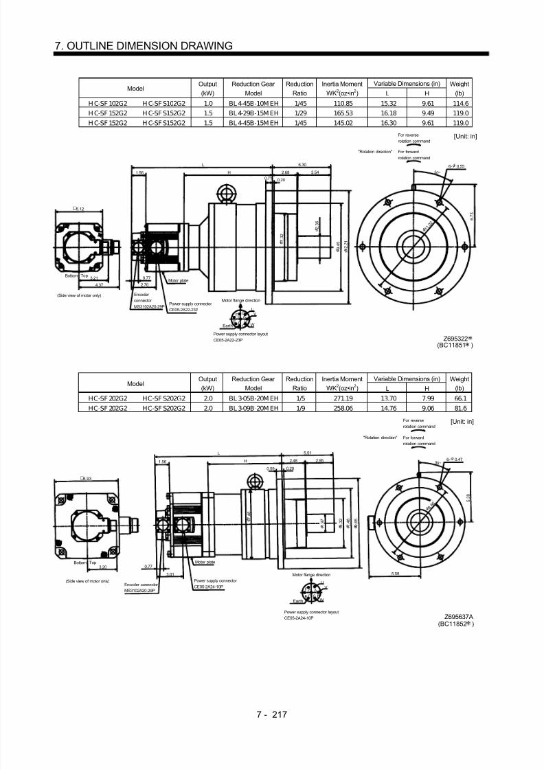
8/10/2019 Servo Motor - Instruction Manual SH(NA)-3181-D (03.00)
http://slidepdf.com/reader/full/servo-motor-instruction-manual-shna-3181-d-0300 296/368
7 - 217
7. OUTLINE DIMENSION DRAWING
Variable Dimensions (in)Model
Output(kW)
Reduction Gear Model
ReductionRatio
Inertia MomentWK2(oz•in 2) L H
Weight(lb)
H C-SF 102G2 H C-SF S102G2 1.0 BL 4-45B-10M EH 1/45 110.85 15.32 9.61 114.6H C-SF 152G2 H C-SF S152G2 1.5 BL 4-29B-15M EH 1/29 165.53 16.18 9.49 119.0H C-SF 152G2 H C-SF S152G2 1.5 BL 4-45B-15M EH 1/45 145.02 16.30 9.61 119.0
0.77
W
VU
L
3.54
6.30
AF GH
BECD
5.12
4.37
3.21
2.70
1.56 H 2.680.71 0.20
2 . 3 6
9 . 4 5
1 2 . 2 1
6- 0.55
7 . 3 2
6 . 7 3
3 0 °
1 1
. 0 2
Z695322
Encoder connector MS3102A20-29P
Power supply connector CE05-2A22-23P
Power supply connector layoutCE05-2A22-23P
Motor plate
Earth
Motor flange direction
[Unit: in]
Bottom Top
(Side view of motor only)
"Rotation direction"
For reverserotation command
For forwardrotation command
(BC11851 )
Variable Dimensions (in)Model
Output(kW)
Reduction Gear Model
ReductionRatio
Inertia MomentWK2(oz•in 2) L H
Weight(lb)
HC-SF 202G2 HC-SF S202G2 2.0 BL 3-05B-20M EH 1/5 271.19 13.70 7.99 66.1HC-SF 202G2 HC-SF S202G2 2.0 BL 3-09B-20M EH 1/9 258.06 14.76 9.06 81.6
5.51
0.20
6.93
3.20 0.77
5 . 3 9
Z695637A
3 0 °
UV
WCD BE AGF
7 . 4 8
7 . 4 8
9 . 6 5
2.95
0.59
6- 0.47
3.01
5 . 3 2
2.48
L
H1.56
5.59
Encoder connector MS3102A20-29P
Power supply connector CE05-2A24-10P
Power supply connector layoutCE05-2A24-10P
Motor plate
Motor flange direction
[Unit: in]
Bottom Top
(Side view of motor only)
"Rotation direction"
For reverserotation command
For forwardrotation command
Earth
1 . 9 7
8 .
6 6
(BC11852 )

8/10/2019 Servo Motor - Instruction Manual SH(NA)-3181-D (03.00)
http://slidepdf.com/reader/full/servo-motor-instruction-manual-shna-3181-d-0300 297/368
7 - 218
7. OUTLINE DIMENSION DRAWING
Variable Dimensions (in)Model
Output(kW)
Reduction Gear Model
ReductionRatio L H
Inertia MomentWK2(oz•in 2)
Weight(lb)
H C-SF 202G2 H C-SF S202G2 2.0 BL 4-20B -20M EH 1/20 10.32 326.0 16.02 125.7H C-SF 202G2 HC-SF S202G2 2.0 BL 4-29B-20M EH 1/29 10.32 288.82 16.02 125.7H C-SF 202G2 HC-SF S202G2 2.0 BL 4-45B-20M EH 1/45 10.43 268.32 16.14 125.7
H C-SF 352G2 H C-SF S352G2 3.5 BL 4-05B-35M EH 1/5 8.78 543.33 16.14 119.0H C-SF 352G2 H C-SF S352G2 3.5 BL 4-09B-35M EH 1/9 10.04 500.14 17.40 141.1H C-SF 352G2 HC-SF S352G2 3.5 BL 4-20B-35M EH 1/20 10.32 541.96 17.68 141.1
6.30
0.20
6.93
3.21 0.77
6 . 7 3
1 1
. 0 2
Z695638A
3 0 °
UV
WCD BE
AGF
9 . 4 5
9 . 4 5
1 2 . 2 1
3.540.71
6- 0.55
3.01
7 . 3 2
2.68
L
H1.56
5.59
Encoder connector MS3102A20-29P
Power supply connector CE05-2A24-10P
Power supply connector layoutCE05-2A24-10P
Motor plate
Earth
Motor flange direction
[Unit: in]
Bottom Top
(Side view of motor only)
"Rotation direction"
For reverserotation command
For forwardrotation command
2 . 3 6
(BC11853 )
Variable Dimensions (in)Model
Output(kW)
Reduction Gear Model
ReductionRatio L H
Inertia MomentWK2(oz•in 2)
Weight(lb)
HC-SF 502G2 5.0 BL 4-05B-50ME H 1/5 16.97 10.04 647.35 127.9HC-SF502G2 5.0 BL4-09B-50MEH 1/9 18.23 8.78 604.15 149.9
5.59
L
H
6.30
0.77
6 . 7 3
BC11067
6- 0.55
9 . 4 5
3.21
3.01
0.71 0.203.54
9 . 4 5
1 2 . 2 1
1.56
7 . 3 2
2 . 3 6
3 0 °
1 1 . 0 2
6.93
Encoder connector MS3102A20-29P
Power supply connector CE05-2A24-10P
Motor plate
UV
WCD BE
AGF
Power supply connector layoutCE05-2A24-10P
Earth
Motor flange direction
Bottom Top
(Side view of motor only)
[Unit: in]
"Rotation direction"
For reverserotation command
For forwardrotation command

8/10/2019 Servo Motor - Instruction Manual SH(NA)-3181-D (03.00)
http://slidepdf.com/reader/full/servo-motor-instruction-manual-shna-3181-d-0300 298/368
7 - 219
7. OUTLINE DIMENSION DRAWING
ModelOutput(kW)
Reduction Gear Model
ReductionRatio
Inertia MomentWK2(oz•in 2)
Weight(lb)
HC-SF 702G2 7.0 BL 4-05B-70ME H 1/5 969.93 147.7
5.91
20.28
8.78
6.30
0.77
6 . 7 3
BC11068
6- 0.55
U
V
WCD
B
A
9 . 4 5
3.21
3.21
0.71 0.20
3.54
9 . 4 5
1 2 . 2 1
1.56
7 . 3 2
3 . 3 6
3 0 °
3.70
1 1 . 0 2
6.93
Encoder connector MS3102A20-29P
Power supply connector CE05-2A32-17P
Motor plate
Power supply connector layoutCE05-2A32-17P
Earth
Motor flange direction
Bottom Top
(Side view of motor only)
[Unit: in]
(b) With electromagnetic brakeVariable
Dimensions (in)ModelOutput(kW)
Reduction Gear Model
ReductionRatio
Inertia MomentWK2(oz•in 2)
L H
Braking Force(oz•in)
Weight(lb)
H C-SF 52BG2 H C-SF S52BG2 0.5 BL 2-05B-05M EH 1/5 52.49 12.17 6.14 1204 33.1H C-SF 52BG2 H C-SF S52BG2 0.5 BL 2-09B-05M EH 1/9 50.57 12.64 6.61 1204 33.1H C-SF 52BG2 H C-SF S52BG2 0.5 BL 2-20B-05M EH 1/20 53.17 13.47 7.44 1204 37.5
H C-SF 102BG2 H C-SF S102BG2 1.0 BL 2-05B-10M EH 1/5 91.17 13.15 6.14 1204 37.5H C-SF 102BG2 H C-SF S102BG2 1.0 BL 2-09B-10M EH 1/9 89.26 13.62 6.61 1204 37.5H C-SF 152BG2 H C-SF S152BG2 1.5 BL 2-05B-15M EH 1/5 125.34 14.13 6.14 1204 41.9
L
1.56
5.12
0.77
4.0
H 1.69 2.17
3.94
1 . 3 8
3 . 7 0
4- 0.474 5 °
W
VU
AF G
H BEC
D
5 . 1 2
4.37
3.21 0.47 0.12
7 .2 8 6
. 3 0
5.51
Z695323
Encoder connector MS3102A20-29P Power supply connector
CE05-2A22-23P
Power supply connector layout(CE05-2A22-23P)
Motor plate
Earth
Motor flange direction
[Unit: in]
Bottom Top(Side view of motor only)
"Rotation direction"
For reverserotation command
For forwardrotation command
Brake
(BC11856 )

8/10/2019 Servo Motor - Instruction Manual SH(NA)-3181-D (03.00)
http://slidepdf.com/reader/full/servo-motor-instruction-manual-shna-3181-d-0300 299/368
7 - 220
7. OUTLINE DIMENSION DRAWING
Variable Dimensions(in)Model
Output(kW)
Reduction Gear Model
ReductionRatio
Inertia MomentWK2(oz•in 2)
L H
Braking Force(oz•in)
Weight(lb)
H C-SF 52BG2 H C-SF S52BG2 0.5 BL 3-29B-05M EH 1/29 60.69 14.57 8.54 1204 70.5H C-SF 52BG2 H C-SF S52BG2 0.5 BL 3-45B-05M EH 1/45 55.36 14.80 8.78 1204 70.5
HC-SF102BG2 HC-SFS102BG2 1.0 BL3-20B-10MEH 1/20 109.76 15.55 8.54 1204 75.0H C-SF 102BG2 H C-SF S102BG2 1.0 BL 3-29B -10M EH 1/29 99.37 15.55 8.54 1204 75.0H C-SF 152BG2 H C-SF S152BG2 1.5 BL 3-09B-15M EH 1/9 144.07 16.22 8.23 1204 79.4HC-SF152BG2 HC-SFS152BG2 1.5 BL3-20B-15MEH 1/20 143.93 16.54 8.54 1204 79.4
W
VU
AF G
H BEC
D
L
1.56
5.51
2.48 2.95
8 .
6 6
6- 0.47
5.12
4.37
3.21
0.59 0.20
H
0.77
4.0
7 . 4 8
5 . 3 2
1 . 9 7
9 . 6 5
5 . 3 9
3 0 °
7 . 4 8
Z695324
Encoder connector MS3102A20-29P
Power supply connector CE05-2A22-23P
Power supply connector layoutCE05-2A22-23P
Motor plate
Earth
Motor flange direction
[Unit: in]
B ot tom Top(Side view of motor only)
"Rotation direction"
For reverserotation command
For forwardrotation command
Brake
(BC11857 )
Variable Dimensions(in)Model
Output(kW)
Reduction Gear Model
ReductionRatio
Inertia MomentWK2(oz•in 2)
L H
Braking Force(oz•in)
Weight(lb)
HC-SF102BG2 HC-SFS102BG2 1.0 BL4-45B-10MEH 1/45 120.15 16.61 9.61 1204 114.6HC-SF152BG2 HC-SFS152BG2 1.5 BL4-29B-15MEH 1/29 174.82 17.48 9.49 1204 123.5HC-SF152BG2 HC-SFS152BG2 1.5 BL4-45B-15MEH 1/45 154.32 17.60 9.61 1204 123.5
W
VU
AF GHBEC
D
L
1.56
6.30
2.68 3.54
1 1 .
0 2
6- 0.55
5.12
4.37
3.21
0.71 0.20
H
0.77
4.0
7 . 3 2
2 . 3 6
9 . 4 5
1 2 . 2 1
6 . 7 3
3 0 °
Z695325
Encoder connector MS3102A20-29P Power supply connector
CE05-2A22-23P
Power supply connector layout
CE05-2A22-23P
Motor plate
Earth
Motor flange direction
[Unit: in]
Bottom Top(Side view of motor only)
"Rotation direction"
For reverserotation command
For forwardrotation command
Brake
(BC11858 )
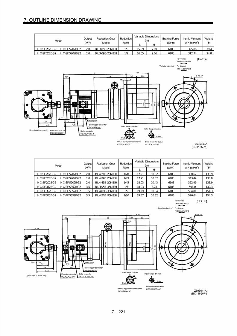
8/10/2019 Servo Motor - Instruction Manual SH(NA)-3181-D (03.00)
http://slidepdf.com/reader/full/servo-motor-instruction-manual-shna-3181-d-0300 300/368
7 - 221
7. OUTLINE DIMENSION DRAWING
Variable Dimensions(in)Model
Output(kW)
Reduction Gear Model
ReductionRatio
L H
Braking Force(oz•in)
Inertia MomentWK2(oz•in 2)
Weight(lb)
H C-SF 202BG2 H C-SF S202BG2 2.0 B L 3-05B-20M EH 1/5 15.59 7.99 6103 325.86 79.4H C-SF 202BG2 H C-SF S202BG2 2.0 B L 3-09B-20M EH 1/9 16.65 9.06 6103 312.74 94.8
5.51
0.20
3.20
0.77
5 . 3 9
Z695640A
3 0 °
UV
WCD BE
AGF
7 . 4 8
7 . 4 8
9 . 6 5
2.95
0.59
6- 0.47
2.72
5 . 3 2
2.48
L
H1.56
5.594.90
A B
4.61
Encoder connector MS3102A20-29P
Power supply connector CE05-2A24-10P
Power supply connector layoutCE05-2A24-10P
Earth
Brake connector MS3102A10SL-4P
Motor flange direction
Brake
Brake connector layoutMS3102A10SL-4P
Motor flange direction
Motor plate
[Unit: in]
(Side view of motor only)
"Rotation direction"
For reverserotation command
For forwardrotation command
8 .
6 6
1 . 9 7
(BC11859 )
Variable Dimensions(in)Model
Output(kW)
Reduction Gear Model
ReductionRatio
L H
Braking Force(oz•in)
Inertia MomentWK2(oz•in 2)
Weight(lb)
HC-SF202BG2 HC-SFS202BG2 2.0 BL4-20B-20MEH 1/20 17.91 10.32 6103 380.67 138.9HC-SF202BG2 HC-SFS202BG2 2.0 BL4-29B-20MEH 1/29 17.91 10.32 6103 343.49 138.9HC-SF202BG2 HC-SFS202BG2 2.0 BL4-45B-20MEH 1/45 18.03 10.43 6103 322.99 138.9H C-SF 352BG2 H C-SF S352BG2 3.5 B L 4-05B-35M EH 1/5 18.03 8.78 6103 598.0 132.3H C-SF 352BG2 H C-SF S352BG2 3.5 BL 4-09B-35M EH 1/9 19.29 10.04 6103 554.81 154.3HC-SF352BG2 HC-SFS352BG2 3.5 BL4-20B-35MEH 1/20 19.57 10.32 6103 596.64 154.3
6.30
0.20
6.93
3.21
0.77
6 . 7 3
1 1
. 0 2
Z695641A
3 0 °
UV
WCD BE AGF
7 . 3 2
9 . 4 5
1 2 . 2 1
3.54
0.71
6- 0.55
4.90
2.68
L
H1.56
9 . 4 5
2.72
4.61
5.59
AB
Encoder connector MS3102A20-29P
Power supply connector CE05-2A24-10P
Power supply connector layoutCE05-2A24-10P
Earth
Brake connector MS3102A10SL-4P
Motor flange direction
Brake
Brake connector layoutMS3102A10SL-4P
Motor flange direction
Motor plate
[Unit: in]
(Side view of motor only)
"Rotation direction"
For reverserotation command
For forwardrotation command
Bottom Top
2 . 3 6
(BC11860 )

8/10/2019 Servo Motor - Instruction Manual SH(NA)-3181-D (03.00)
http://slidepdf.com/reader/full/servo-motor-instruction-manual-shna-3181-d-0300 301/368
7 - 222
7. OUTLINE DIMENSION DRAWING
Variable Dimensions (in)Model
Output(kW)
Reduction Gear Model
ReductionRatio L H
Inertia MomentWK2(oz•in 2)
Weight(lb)
H C-SF 502BG2 5.0 BL 4-05B-50M EH 1/5 18.86 8.78 680.70 141.1H C-SF 502BG2 5.0 BL 4-09B-50M EH 1/9 20.12 10.04 680.70 163.1
5.59
L
H
6.30
6.93
4.61
0.77
2.72
6 . 7 3
BC11069
6- 0.55
UV
WCD BE
AGF
9 . 4 5
3.21
4.90
0.71 0.203.54
9 . 4 5
1 2 . 2 1
1.56
7 . 3 2
3 . 3 6
3 0 °
1 1 . 0 2
A B
Encoder connector MS3102A20-29P Power supply connector
CE05-2A24-10P
Power supply connector layoutCE05-2A24-10P
Earth
Brake connector MS3102A10SL-4P
Motor flange direction
Brake
Brake connector layoutMS3102A10SL-4P
Motor flange direction
Motor plate
[Unit: in]
(Side view of motor only)
"Rotation direction"
For reverserotation command
For forwardrotation command
Bottom Top
ModelOutput(kW)
Reduction Gear Model
ReductionRatio
Inertia MomentWK2(oz•in 2)
Weight(lb)
HC-SF702BG2 7.0 BL4-05B-70MEH 1/5 1024.60 160.9
5.91
22.17
8.78
6.30
6.93
4.61
0.77
2.72
6 . 7 3
BC11070
6- 0.55
U
V
WCD
B
A
9 . 4 5
3.21
B A
5.10
0.71 0.20
3.54
9 . 4 5
1 2 . 2 1
1.56
7 . 3 2
3 . 3 6
3 0 °
3.70
1 1 . 0 2
Encoder connector MS3102A20-29P
Power supply connector CE05-2A32-17P
Power supply connector layoutCE05-2A32-17P
Earth
Brake connector MS3102A10SL-4P
Motor flange direction
Brake
Brake connector layoutMS3102A10SL-4P
Motor flange direction
Motor plate
[Unit: in]
(Side view of motor only)
Bottom Top

8/10/2019 Servo Motor - Instruction Manual SH(NA)-3181-D (03.00)
http://slidepdf.com/reader/full/servo-motor-instruction-manual-shna-3181-d-0300 302/368
7 - 223
7. OUTLINE DIMENSION DRAWING
7.2.4 HC-RF•HC-RFS Series
(1) Standard (without electromagnetic brake, without reduction gear)Variable Dimensions (in)
ModelOutput(kW)
Inertia MomentWK2(oz•in 2) L KL
Weight(lb)
HC-RF103 HC-RFS103 1.0 8.20 5.79 2.80 8.6HC-RF153 HC-RFS153 1.5 10.39 6.77 3.78 11.0HC-RF203 HC-RFS203 2.0 12.58 7.76 4.76 13.7
1.61
3 . 7 8
4 5 °
4. 5 3 5 .3 2
3 . 2 1
0.77
MS3102A20-29P CE05-2A22-23P W
VU
AFG
H BEC
D
KL
L
1.560.39 0.12
1.58
S30457B
0 . 9 5
3 . 7 4
1.77
(BC11697 )
Bottom
Top
Encoder connector Power supply connector
Oil seal
Motor flange direction
Earth
Power supply connector layout(CE05-2A22-23P)
[Unit: in]
Use hexagon socket head cap screw.
Motor plate
(Opposite side)
Bottom
Top
Z694853
3.94
4- 0.35 mounting hole
Variable Dimensions (in)Model
Output(kW) L KL
Inertia MomentWK2(oz•in 2)
Weight(lb)
HC-RF353 3.5 8.543 5.827 47.02 26.5HC-RF503 5.0 10.787 8.071 65.609 37.5
[Unit: in]
2.283Motor plate
V
U
WD C
B
AGF
E
4 . 7 2 4
Power supply connector layoutCE05-2A24-10P
0.12
2.48
0.471.56
1 . 1 0 2
Top
Bottom
L
(Opposite side)
Bottom
Top
3 . 2 1
0.77
5.118
4 5 °
1.811
KL
MS3102A20-29PEncoder connector
CE05-2A24-10PPower supply connector
S30457BOil seal
Motor flange direction
Earth
Use hexagon sockethead cap screw.
4- 0.354 mounting hole
Z695780
4 . 3 3 1
5. 7 0 9
6 .4 9 6
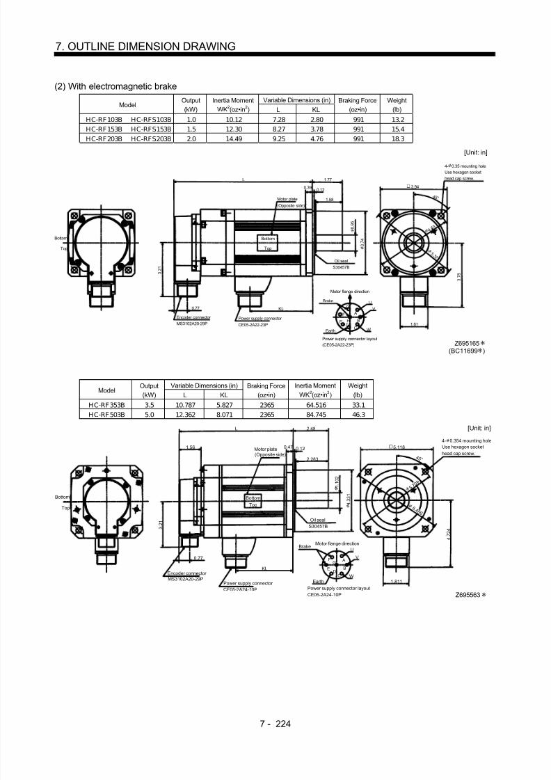
8/10/2019 Servo Motor - Instruction Manual SH(NA)-3181-D (03.00)
http://slidepdf.com/reader/full/servo-motor-instruction-manual-shna-3181-d-0300 303/368
7 - 224
7. OUTLINE DIMENSION DRAWING
(2) With electromagnetic brakeVariable Dimensions (in)
ModelOutput(kW)
Inertia MomentWK2(oz•in 2) L KL
Braking Force(oz•in)
Weight(lb)
HC-RF103B HC-RFS103B 1.0 10.12 7.28 2.80 991 13.2HC-RF153B HC-RFS153B 1.5 12.30 8.27 3.78 991 15.4HC-RF203B HC-RFS203B 2.0 14.49 9.25 4.76 991 18.3
KL0.77
W
VU
MS3102A20-29P CE05-2A22-23P
3 . 2 1 S30457B
L 1.77
0.39 0.12
1.58
AF
G
H BEC
D 1.61
3 . 7 8
4 5 °
Bottom
Top
Encoder connector Power supply connector
Oil seal
Motor flange direction
Earth
Power supply connector layout(CE05-2A22-23P)
[Unit: in]
Use hexagon sockethead cap screw.
4- 0.35 mounting hole
Motor plate
(Opposite side)
Bottom
Top
Brake
Z695165
3.94
4. 5 3
5 .3 2
3 . 7 4
0 . 9 5
(BC11699 )
Variable Dimensions (in)Model
Output(kW) L KL
Braking Force(oz•in)
Inertia MomentWK2(oz•in 2)
Weight(lb)
HC-RF353B 3.5 10.787 5.827 2365 64.516 33.1HC-RF503B 5.0 12.362 8.071 2365 84.745 46.3
(Opposite side)
0.77
W
V
U
A
B
CD
E
FG
Power supply connector layoutCE05-2A24-10P
MS3102A20-29P
CE05-2A24-10P
3 . 2 1
L 2.48
0.47 0.12
2.283
1.811
4 . 7 2 4
5.118
BottomTop
4 5 °
[Unit: in]
Bottom
Top
1.56 Motor plate
Brake
KLEncoder connector
Power supply connector
S30457BOil seal
Motor flange direction
Earth
Use hexagon sockethead cap screw.
Z695563
4- 0.354 mounting hole
4 . 3 3 1
1 . 1 0 2
6 .4 9 6
5. 7 0 9

8/10/2019 Servo Motor - Instruction Manual SH(NA)-3181-D (03.00)
http://slidepdf.com/reader/full/servo-motor-instruction-manual-shna-3181-d-0300 304/368
7 - 225
7. OUTLINE DIMENSION DRAWING
(3) With reduction gear for precision application(a) Without electromagnetic brake
Variable Dimensions (in)Model
Output(kW)
Reduction Gear Model
ReductionRatio
Inertia MomentWK2(oz•in 2) L KL
Weight(lb)
H C-RF 103G2 H C-RF S103G2 1.0 BL 2-05B-10M EK D 1/5 27.06 11.85 6.06 26.2H C-RF 103G2 H C-RF S103G2 1.0 BL 2-09B-10M EK D 1/9 25.15 12.32 6.54 26.2H C-RF 153G2 H C-RF S153G2 1.5 BL 2-05B-15M EK D 1/5 29.25 12.84 6.06 28.7H C-RF 203G2 H C-RF S203G2 2.0 BL 2-05B-20M EK D 1/5 31.44 13.82 6.06 31.3
L
1.56
3.94
0.77
2.99
3.21
3.78
H0.47 0.12
1.69 2.17
5 . 2 0
4 5 °
W
VU
AFGH
BEC
D
Z695327A
Encoder connector MS3102A20-29P
Power supply connector CE05-2A22-23P
Power supply connector layout(CE05-2A22-23P)
Earth
Motor flange direction
[Unit: in]
Bot tom Top
(Side view of motor only)
"Rotation direction"
For reverserotation command
For forwardrotation command
Motor plate(Opposite side)
5.51
4- 0.47
6. 3 07 .2 8
5 . 1 2
3 . 7 0
1 . 3 8
3.94
Variable Dimensions (in)Model
Output(kW)
Reduction Gear Model
ReductionRatio
Inertia MomentWK2(oz•in 2) L H LI
Weight(lb)
HC-RF103G2 HC-RFS103G2 1.0 BL3-20B-10MEKD 1/20 45.65 13.94 8.15 4.13 63.7HC-RF103G2 HC-RFS103G2 1.0 BL3-29B-10MEKD 1/29 35.27 13.94 8.15 4.13 63.7HC-RF103G2 HC-RFS103G2 1.0 BL3-45B-10MEKD 1/45 29.93 14.33 8.54 4.53 63.7H C-RF 153G2 H C-RF S153G2 1.5 BL 3-09B -15M E KD 1/9 36.50 14.76 7.99 3.98 66.1HC-RF153G2 HC-RFS153G2 1.5 BL3-20B-15MEKD 1/20 47.84 14.92 8.15 4.13 66.1HC-RF153G2 HC-RFS153G2 1.5 BL3-29B-15MEKD 1/29 37.45 14.92 8.15 4.13 66.1H C-RF 203G2 H C-RF S203G2 2.0 BL 3-09B -20M E KD 1/9 38.68 15.75 7.99 3.98 68.8HC-RF203G2 HC-RFS203G2 2.0 BL3-20B-20MEKD 1/20 50.03 15.91 8.15 4.13 68.8
W
VU
AF G
H BE
CD
L
1.56
5.51
2.48 2.95
3.78
3.21
0.59 0.20
H
0.77
2.99
3 0 °
LI
Encoder connector MS3102A20-29P
Power supply connector CE05-2A22-23P
Power supply connector layout(CE05-2A22-23P)
Earth
Motor flange direction
[Unit: in]
Bottom Top
(Side view of motor only)
"Rotation direction"
For reverserotation command
For forwardrotation command
(Opposite side)Motor plate
Z695328
6- 0.47
8 . 6 6
9 . 6 5
7 . 4 8
1 . 9 7 5 .
3 2 7 . 4 8
3.94
5 . 3 7

8/10/2019 Servo Motor - Instruction Manual SH(NA)-3181-D (03.00)
http://slidepdf.com/reader/full/servo-motor-instruction-manual-shna-3181-d-0300 305/368

8/10/2019 Servo Motor - Instruction Manual SH(NA)-3181-D (03.00)
http://slidepdf.com/reader/full/servo-motor-instruction-manual-shna-3181-d-0300 306/368
7 - 227
7. OUTLINE DIMENSION DRAWING
Variable Dimensions (in) WeightModel
Output(kW)
Reduction Gear Model
ReductionRatio
Inertia MomentWK2(oz•in 2) L H LI (lb)
H C-RF 353G2 3.5 BL 4-09B-35M EK D 1/9 115.363 18.504 9.961 4.961 125.7H C-RF 353G2 3.5 BL 4-20B-35M E KD 1/20 157.462 18.504 9.961 4.961 125.7H C-RF 353G2 3.5 BL 4-29B-35M E KD 1/29 120.284 18.504 9.961 4.961 125.7
H C-RF 503G2 5.0 BL 4-05B-50M EK D 1/5 177.145 19.488 8.701 3.701 114.6H C-RF 503G2 5.0 BL 4-09B-50M EK D 1/9 133.952 20.748 9.961 4.961 136.7H C-RF 503G2 5.0 BL 4-20B-50M E KD 1/20 176.052 20.748 9.961 4.961 136.7
W
VU
Power supply connector layoutCE05-2A24-10P
AFGBE CD
Power supply connector CE05-2A24-10P
Bottom Top
L
1.56
2.68
6.30
3.546- 0.55
3.21
4.724
0.71 0.20
H
Motor plate0.77
2.736
6 . 7 3
3 0 °
2 . 3 6
LI
[Unit: in]
Encoder connector MS3102A20-29P
Earth
Motor flange direction
"Rotation direction"
For reverserotation command
For forwardrotation command
(Side view of motor only)
Z695992
1 1 . 0 2
9 . 4 5
1 2 . 2 1
7 . 3 2 3
9 . 4 5
5.118
(b) With electromagnetic brakeVariable
Dimensions (in)ModelOutput(kW)
Reduction Gear Model
ReductionRatio
Inertia MomentWK2(oz•in 2)
L H
Braking Force(oz•in)
Weight(lb)
HC-RF 103BG2 HC-RF S103BG2 1.0 BL 2-05B-10M EK D 1/5 28.98 13.35 6.06 991 30.9HC-RF 103BG2 HC-RF S103BG2 1.0 BL 2-09B-10M EK D 1/9 27.06 13.82 6.54 991 30.9HC-RF 153BG2 HC-RF S153BG2 1.5 BL 2-05B-15M EK D 1/5 31.16 14.33 6.06 991 33.3HC-RF 203BG2 HC-RF S203BG2 2.0 BL 2-05B-20M EK D 1/5 33.35 15.32 6.06 991 35.9
L
1.56
3.94
0.77
4.47
3.21
3.78
H0.47 0.12
1.69 2.17 4 5 °
W
VU
A
FG
H BECD
Encoder connector MS3102A20-29P
Power supply connector CE05-2A22-23P
Power supply connector layout
(CE05-2A22-23P)
Earth
Motor flange direction
[Unit: in]
Bot tom Top
(Side view of motor only)
"Rotation direction"
For reverserotation command
For forwardrotation command
(Opposite side)Motor plate
Brake
Z695330(BC11868 )
4- 0.47
6. 3 07 .2 8
5 . 1 2
1 . 3 8
3 . 7 0
3.94
5.51
5 . 2 0

8/10/2019 Servo Motor - Instruction Manual SH(NA)-3181-D (03.00)
http://slidepdf.com/reader/full/servo-motor-instruction-manual-shna-3181-d-0300 307/368
7 - 228
7. OUTLINE DIMENSION DRAWING
Variable Dimensions(in)Model
Output(kW)
Reduction Gear Model
ReductionRatio
Inertia MomentWK2(oz•in 2)
L H LI
Braking Force(oz•in)
Weight(lb)
H C-RF 103BG2 H C-RF S103BG2 1.0 BL 3-20B-10M EK D 1/20 47.57 15.43 8.15 4.13 991 68.3H C-RF 103BG2 H C-RF S103BG2 1.0 BL 3-29B-10M EK D 1/29 37.18 15.43 8.15 4.13 991 68.3H C-RF 103BG2 H C-RF S103BG2 1.0 BL 3-45B-10M EK D 1/45 31.85 15.83 8.54 4.53 991 68.3H C-RF 153B G2 H C-RF S153BG2 1.5 BL 3-09B-15M EK D 1/9 38.41 16.26 7.99 3.98 991 70.8H C-RF 153BG2 H C-RF S153BG2 1.5 BL 3-20B-15M EK D 1/20 49.75 16.42 8.15 4.13 991 70.8H C-RF 153BG2 H C-RF S153BG2 1.5 BL 3-29B-15M EK D 1/29 39.37 16.42 8.15 4.13 991 70.8H C-RF 203B G2 H C-RF S203BG2 2.0 BL 3-09B-20M EK D 1/9 40.60 17.24 7.99 3.98 991 73.4H C-RF 203BG2 H C-RF S203BG2 2.0 BL 3-20B-20M EK D 1/20 51.94 17.40 8.15 4.13 991 73.4
W
VU
A
F G
H BEC
D
L
1.56 2.48
5.51
2.95
3.213.78
0.59 0.20
H
0.774.47
5 . 3 7
3 0 °
LI
Encoder connector MS3102A20-29P
Power supply connector CE05-2A22-23P
Power supply connector layout(CE05-2A22-23P)
Earth
Motor flange direction
[Unit: in]
B ott om Top
(Side view of motor only)
"Rotation direction"
For reverserotation command
For forwardrotation command
(Opposite side)Motor plate
Brake
Z695331
(BC11869 )
6- 0.47
8 . 6 6
9 . 6 5
7 . 4 8
1 . 9 7 5 .
3 2 7 . 4 8
3.94
Variable Dimensions(in)Model
Output(kW)
Reduction Gear Model
ReductionRatio
Inertia MomentWK2(oz•in 2)
L H LI
Braking Force(oz•in)
Weight(lb)
H C-RF 153BG2 H C-RF S153B G2 1.5 BL 4-45B-15M EK D 1/45 48.66 17.64 9.37 5.35 991 114.9H C-RF 203BG2 H C-RF S203B G2 2.0 BL 4-29B-20M EK D 1/29 71.35 18.23 8.98 4.96 991 117.5H C-RF 203BG2 H C-RF S203B G2 2.0 BL 4-45B-20M EK D 1/45 50.85 18.62 9.37 5.35 991 117.5
W
VU
AF G
H BEC
D
L
1.56 2.68
6.30
3.54
3.21
3.78
0.71 0.20
H
0.77
4.47
6 . 7 3
3 0 °
LI
Encoder connector MS3102A20-29P
Power supply connector CE05-2A22-23P
Power supply connector layout(CE05-2A22-23P)
Earth
Motor flange direction
[Unit: in]
Bot tom Top
(Side view of motor only)
"Rotation direction"
For reverserotation command
For forwardrotation command
(Opposite side)Motor plate
Brake
Z695332(BC11870 )
6- 0.55
1 1 . 0 2
1 2 . 2 1
9 . 4 5
2 . 3 6 7 .
3 2 9 . 4 5
3.94
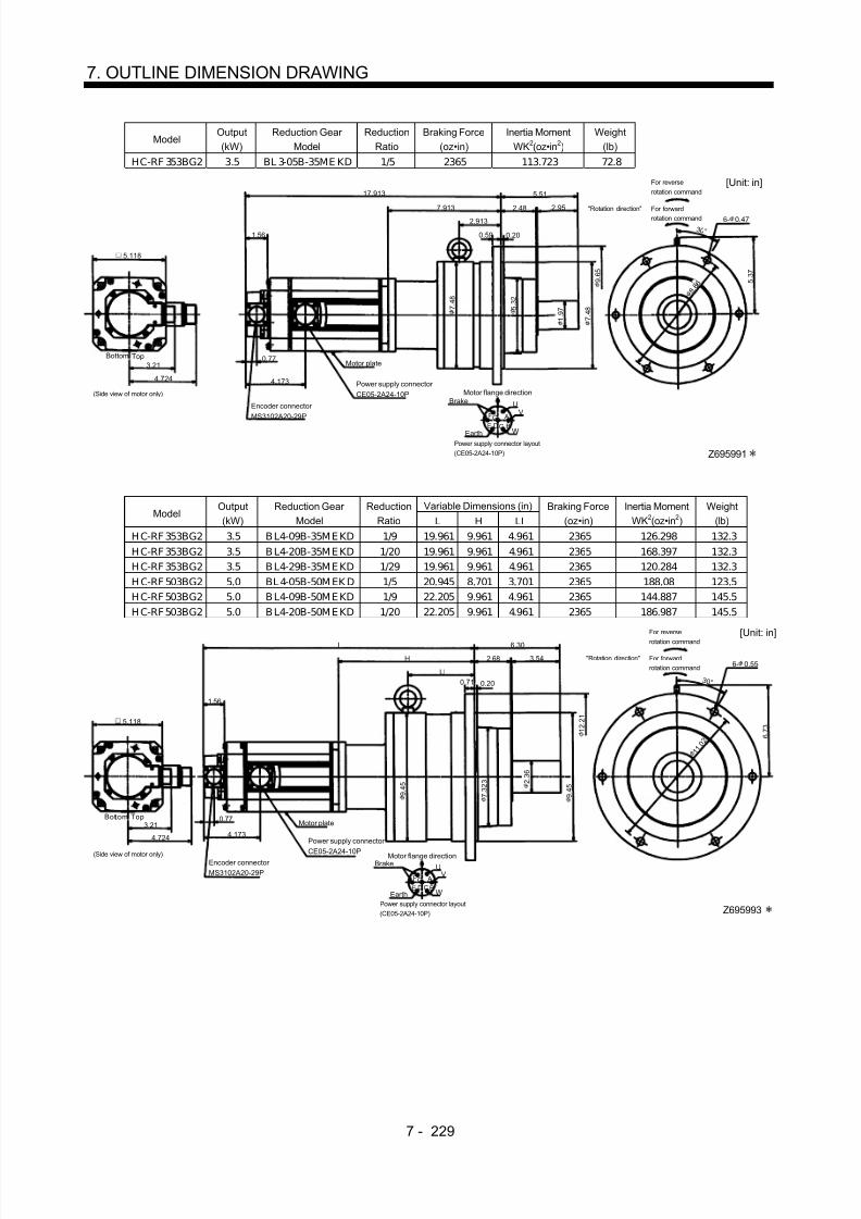
8/10/2019 Servo Motor - Instruction Manual SH(NA)-3181-D (03.00)
http://slidepdf.com/reader/full/servo-motor-instruction-manual-shna-3181-d-0300 308/368
7 - 229
7. OUTLINE DIMENSION DRAWING
ModelOutput(kW)
Reduction Gear Model
ReductionRatio
Braking Force(oz•in)
Inertia MomentWK2(oz•in 2)
Weight(lb)
HC-RF 353BG2 3.5 BL 3-05B-35ME KD 1/5 2365 113.723 72.8
W
VU
AFG
BE CD
Bottom Top
17.913
1.56
2.48
5.51
2.95
3.21
4.724
0.59 0.20
7.913
Motor plate0.77
4.173
5 . 3 7
3 0 °
2.913
[Unit: in]
Encoder connector MS3102A20-29P
Power supply connector CE05-2A24-10P
Earth
Motor flange directionBrake
Power supply connector layout(CE05-2A24-10P)
"Rotation direction"
For reverserotation command
For forwardrotation command
(Side view of motor only)
Z695991
6- 0.47
8 . 6 6
9 . 6 5
7 . 4 8
1 . 9 7 5 .
3 2 7 . 4 8
5.118
Variable Dimensions (in)Model
Output(kW)
Reduction Gear Model
ReductionRatio L H LI
Braking Force(oz•in)
Inertia MomentWK2(oz•in 2)
Weight(lb)
H C-RF 353BG2 3.5 B L4-09B-35M E KD 1/9 19.961 9.961 4.961 2365 126.298 132.3H C-RF 353BG2 3.5 B L4-20B-35M E KD 1/20 19.961 9.961 4.961 2365 168.397 132.3H C-RF 353BG2 3.5 B L4-29B-35M E KD 1/29 19.961 9.961 4.961 2365 120.284 132.3H C-RF 503BG2 5.0 BL 4-05B-50M EK D 1/5 20.945 8.701 3.701 2365 188.08 123.5H C-RF 503BG2 5.0 B L4-09B-50M E KD 1/9 22.205 9.961 4.961 2365 144.887 145.5H C-RF 503BG2 5.0 B L4-20B-50M E KD 1/20 22.205 9.961 4.961 2365 186.987 145.5
W
VU
AFGBE CD
Bottom Top
L
1.56
2.68
6.30
3.54
3.21
4.724
0.71 0.20
H
Motor plate0.77
4.173
6 . 7 3
3 0 °
LI
[Unit: in]
Encoder connector MS3102A20-29P
Power supply connector
CE05-2A24-10P
Earth
Motor flange directionBrake
Power supply connector layout(CE05-2A24-10P)
"Rotation direction"
For reverse
rotation command
For forwardrotation command
(Side view of motor only)
Z695993
6- 0.55
1 1 . 0 2
1 2 . 2 1
9 . 4 5 2 .
3 6
9 . 4 5
7 . 3 2 3
5.118

8/10/2019 Servo Motor - Instruction Manual SH(NA)-3181-D (03.00)
http://slidepdf.com/reader/full/servo-motor-instruction-manual-shna-3181-d-0300 309/368
7 - 230
7. OUTLINE DIMENSION DRAWING
7.2.5 HC-UF 2000r/min•HC-UFS 2000r/min Series
(1) Standard (without electromagnetic brake)
ModelOutput(kW)
Inertia MomentWK2(oz•in 2)
Weight(lb)
HC-UF72 HC-UFS72 0.75 56.861 17.6
Top
A
BC
DE
FG
U
V
W
Oil seal
S30457B
Motor plate
2-M6 screw
4 0 °
4 5 °
1.562.165
0.512 0.12
BottomTop
0.77
3 . 2 1
5 . 6 6 9
[Unit: in]
1.732
H1.496
4.35
1.97
Bottom
Encoder connector MS3102A20-29P
Power supply connector CE05-2A22-23P
Earth
Motor flange direction
Power supply connector layout(CE05-2A22-23P)
(Oppositeside)
Use hexagon sockethead cap screw.
4- 0.53 mounting hole
Z695911(BC11711 )
9 .0 5 5
7. 8 7
8 . 4
6 5
4 . 5
6.93
0 . 8 6 6
ModelOutput(kW)
Inertia MomentWK2(oz•in 2)
Weight(lb)
H C-U F152 H C-U FS152 1.5 120.831 24.3
Top
Bottom
A
BCDEF
G
U
V
W
Motor plate(Opposite side)
2-M6 screw
4 0 °
4 5 °
1.562.165
0.512 0.12
BottomTop
0.77
3 . 2 1
5 . 6 6 9
[Unit: in]
1.732H
1.87
4.724
1.97
Oil seal
S30457B
Encoder connector MS3102A20-29P
Power supply connector CE05-2A22-23P
Motor flange direction
Power supply connector layout(CE05-2A22-23P)
Earth Use hexagon sockethead cap screw.
4- 0.53 mounting hole
7. 8 7
9 .0 5 5
8 . 4
6 5
(BC11712 )Z695912A
1 . 1 0 2
4 . 5
6.93

8/10/2019 Servo Motor - Instruction Manual SH(NA)-3181-D (03.00)
http://slidepdf.com/reader/full/servo-motor-instruction-manual-shna-3181-d-0300 310/368
7 - 231
7. OUTLINE DIMENSION DRAWING
Variable Dimensions (in)Model
Output(kW) L KL
Inertia MomentWK2(oz•in 2)
Weight(lb)
HC-UF 202 H C-U FS202 2.0 4.646 1.673 208.856 35.3HC-UF 352 HC-UFS352 3.5 5.591 2.618 418.26 44.1HC-UF502 5.0 6.535 3.563 628.756 52.9
A
BCDE
FG
U
V
W
Motor plate(Opposite side)
2-M8 screw
3 7. 5 °
4 5 °
1.562.559
0.63 0.157
BottomTop
0.77
3 . 2 1
6 . 4 5 7
[Unit: in]
1.85
KL
L
2.362
(Use hexagon socket head cap screw.)
Top
Bottom
Encoder connector MS3102A20-29P
Power supply connector CE05-2A24-10P
Motor flange direction
Power supply connector layout(CE05-2A24-10P)
Oil seal
S40608B
Z695914
8.661
1 0 .6 3
9. 2 5 2
9 . 8
4 3
1 . 3 7 8
7 . 8 7 4
(BC11713 )
4- 0.53 mounting hole
(2) With electromagnetic brakeModel Output(kW) Braking Force(oz•in) Inertia Moment WK 2(oz•in 2) Weight(lb)
HC-UF72B HC-UFS72B 0.75 1204 67.796 22.0
Top
Bottom
A
BCDEF
G
U
V
W
Oil seal
S30457B
Motor plate(Oppositeside)
2-M6 screw
4 0 °
4 5 °
1.56
2.1650.512 0.12
BottomTop
0.77
5 . 6 6 9
[Unit: in]
1.732
H1.496
5.669
Brake
Encoder connector MS3102A20-29P
Power supply connector CE05-2A22-23P
Motor flange direction
Power supply connector layout(CE05-2A22-23P)
EarthUse hexagon sockethead cap screw.
Z695981A(BC11714 )
4- 0.53 mounting hole
7. 8 7
9 .0 5 5
8 . 4
6 5
6.93
4 . 5
0 . 8 6 6
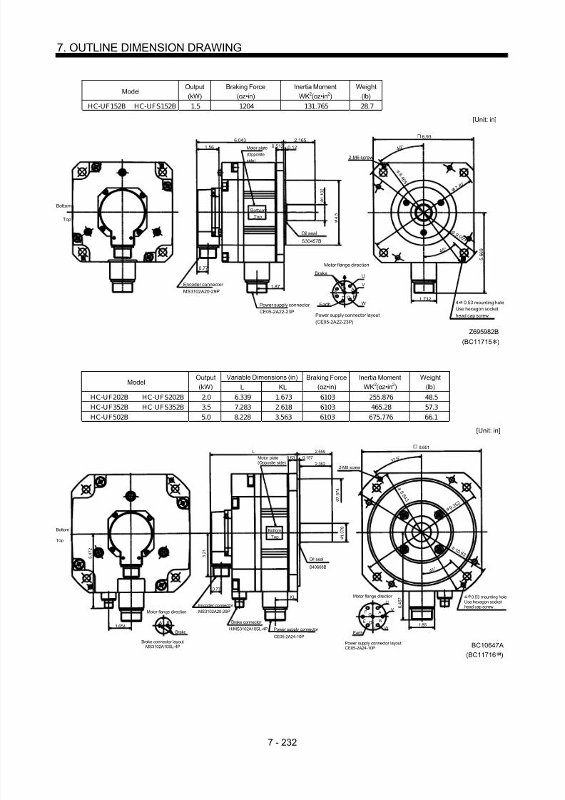
8/10/2019 Servo Motor - Instruction Manual SH(NA)-3181-D (03.00)
http://slidepdf.com/reader/full/servo-motor-instruction-manual-shna-3181-d-0300 311/368
7 - 232
7. OUTLINE DIMENSION DRAWING
ModelOutput(kW)
Braking Force(oz•in)
Inertia MomentWK2(oz•in 2)
Weight(lb)
HC-UF152B HC-UFS152B 1.5 1204 131.765 28.7
A
BCDEF
G
U
V
W
2-M6 screw
4 0 °
4 5 °
1.562.165
0.512 0.12
5 . 6 6 9
[Unit: in]
1.732
H1.87
6.043
Top
Bottom
Oil seal
S30457B
Motor plate(Oppositeside)
BottomTop
0.77Brake
Encoder connector MS3102A20-29P
Power supply connector CE05-2A22-23P
Motor flange direction
Power supply connector layout(CE05-2A22-23P)
EarthUse hexagon sockethead cap screw.
(BC11715 )
Z695982B
4- 0.53 mounting hole
7. 8 7
9 .0 5 5
8 . 4
6 5
1 . 1 0 2
4 . 5
6.93
Variable Dimensions (in)Model
Output(kW) L KL
Braking Force(oz•in)
Inertia MomentWK2(oz•in 2)
Weight(lb)
HC-UF202B HC-UFS202B 2.0 6.339 1.673 6103 255.876 48.5HC-UF352B HC-UFS352B 3.5 7.283 2.618 6103 465.28 57.3
HC-UF502B 5.0 8.228 3.563 6103 675.776 66.1
Top
Bottom
1.654
Motor flange direction
Brake connector layoutMS3102A10SL-4P
Brake
A B
Encoder connector MS3102A20-29P
Brake connector
H/MS3102A10SL-4P Power supply connector
CE05-2A24-10P
KL Motor flange direction
Power supply connector layoutCE05-2A24-10P
A
B
CDE
F G
U
V
WEarth
Oil sealS40608B
Motor plate(Opposite side)
2-M8 screw
3 7. 5 °
4 5 °
2.559
2.3620.157
L
BottomTop
0.77
3 . 2 1
6 . 4 5 7
5 . 4 7 2
[Unit: in]
BC10647A
1.85
0.63
(BC11716 )
4- 0.53 mounting holeUse hexagon sockethead cap screw.
1 0 .6 3
9. 2 5 2
9 . 8
4 3
8.661
1 . 3 7 8
7 . 8 7 4

8/10/2019 Servo Motor - Instruction Manual SH(NA)-3181-D (03.00)
http://slidepdf.com/reader/full/servo-motor-instruction-manual-shna-3181-d-0300 312/368
7 - 233
7. OUTLINE DIMENSION DRAWING
7.2.6 HC-UF 3000r/min Series
(1) Standard (without electromagnetic brake)
ModelOutput
(W)Inertia Moment
WK2(oz•in 2)Weight
(lb)
HC-UF13 100 0.361 1.8
[Unit: in]
Bottom
Top
Motor plate(Opposite side)
1.059
2.756
Power supply lead 4-AWG19 11.8in
(With end-insulated round crimping terminal 1.25-4) Red: Phase U White: Phase V Black: Phase W Green/yellow: Earth
Encoder cable 11.8in
With connector 1-172169-9(AMP make)
0.984
0.20 0.23
0.12
1 . 9 6 9
1 . 5 7 5
0 . 3 1 5
Oil seal
S102071.299
0.390
Bottom
Top
Bottom
Top
Bottom
Top
2.362
4- 0.228
0.787
1 . 5 7 5
1 . 6 8 5
BC11740A
Motor plateTUV plate
Caution plate
2 .7 5 6
4 5 °
R 5
Variable Dimensions (in)Model
Output(W) L KL
Inertia MomentWK2(oz•in 2)
Weight(lb)
HC-UF23 200 2.953 1.724 1.318 3.3HC-UF43 400 3.543 2.315 1.996 3.7
1 . 9 6 9
1.059
L 1.181
0.315 0.256
[Unit: in]
Top
BottomTop
Bottom
Top
Bottom
BC11513A
Motor plate(Opposite side)
Encoder cable 11.8inPower supply lead 4-AWG19 11.8in
With connector 1-172169-9(AMP make)
(With end-insulated round crimping terminal 1.25-4) Red: Phase U White: Phase V Black: Phase W Green/yellow: Earth
Oil sealSC15307
0 . 5 5 1
0.12
3 .5 4 3
3.15
4- 0.26Motor plate
TUV plate
0.390
KL
2 . 2 0 5
2 . 1 6 5
2 . 7 5 6
0.945
4 5 °
R 7

8/10/2019 Servo Motor - Instruction Manual SH(NA)-3181-D (03.00)
http://slidepdf.com/reader/full/servo-motor-instruction-manual-shna-3181-d-0300 313/368
7 - 234
7. OUTLINE DIMENSION DRAWING
ModelOutput
(W)Inertia Moment
WK2(oz•in 2)Weight
(lb)
HC-UF73 750 32.258 11.0
BC11357A1.059
2 . 8 4
3.35 1.58
0.10
0.39 4 5 ° 0.138
1.28
2 . 9 9
0.219
2.76
[Unit: in]
Oil sealS20357
Encoder cable 11.8inWith connector 1-172169-9(AMP make)
Power supply lead 4-AWG19 11.8in
Motor plate(Opposite side)
Bottom
Top
(With end-insulated round crimping terminal 1.25-4) Red: Phase U White: Phase V Black: Phase W
Green/yellow: Earth
Motor plate
3 . 1 5
4 . 3 3
0 . 7 5
4.84
5 . 7 1
6. 5 0
4- 0.35
TUV plate
Cautionplate
Bottom
Top
BottomTop
0.787
Bottom
Top
(2) With electromagnetic brake
ModelOutput
(W)Braking Force
(oz•in)Inertia Moment
WK2(oz•in 2)Weight
(lb)HC-UF13B 100 45 0.405 2.6
1 . 6 8 5
[Unit: in]
BC11767A
Motor plate(Opposite side)
Encoder cable 11.8in
Power supply lead 4-AWG19 11.8in1.059
1 . 5 7 5
With connector 1-172169-9(AMP make)
(With end-insulated round crimping terminal 1.25-4) Red: Phase U White: Phase V Black: Phase W Green/yellow: Earth
Oil sealSC10207
3.937 0.984
0.12
0.20
Bottom
Top
4 5 °
R 5
0.23
Brake cable2
1 . 5 7 5
1 . 9 6 9
0 . 3 1 5
4- 0.228
2.362
0.787
TUV plateMotor plate
Cautionplate
Bottom
Top
Bottom
Top
Bottom
Top
1.8391.299
0.390
2 .7 5 6
Tough-rubber sheath cable 2-0.75 11.8in(With end-insulated round crimping terminal 0.05-4)

8/10/2019 Servo Motor - Instruction Manual SH(NA)-3181-D (03.00)
http://slidepdf.com/reader/full/servo-motor-instruction-manual-shna-3181-d-0300 314/368
7 - 235
7. OUTLINE DIMENSION DRAWING
Variable Dimensions (in)Model
Output(W) L KL
Braking Force(oz•in)
Inertia MomentWK2(oz•in 2)
Weight(lb)
HC-UF23B 200 4.291 1.724 184 1.766 4.9HC-UF43B 400 4.882 2.315 184 2.444 5.3
[Unit: in]
BC11515A
Motor plate(Opposite side)
Encoder cable 11.8in Power supply lead 4-AWG19 11.8in
1.059
1 . 9 6 9
With connector 1-172169-9(AMP make)
(With end-insulated round crimping terminal 1.25-4) Red: Phase U White: Phase V Black: Phase W Green/yellow: Earth
Oil sealSC15307
L 1.181
0.12
0.315
Bottom
Top
4 5 °
R 7
0.256
Brake cableTough-rubber sheath cable2-0.75 1.18in(With end-insulated roundcrimping terminal 0.05-4)
TUV plate
Motor plate
Bottom
Top
1.858 KL
0 . 5 5 1
2 . 2 0 5
2 . 7 5 6
4- 0.26
3.150
3 .5 4 3
2 . 1 6 5
Bottom
Top
0.390 0.945
2
ModelOutput
(W)Braking Force
(oz•in)Inertia Moment
WK2(oz•in 2)Weight
(lb)HC-UF73B 750 339.87 33.35 13.7
4.370
1.059
5 . 7 0 9
4 5 ° 0.394
BC11358A
2 . 8 3 5
1.575
1.28
0.138
0.10
6. 4 9 6
2 . 9 9
0.787
2.19
2.993.78
Oil sealSC20357
Encoder cable 11.8in
With connector 1-172169-9(AMP make)
Brake cable
Power supply lead 4-AWG19 11.8in
[Unit: in]
Motor plate(Opposite side)
Tough-rubber sheath cable2-0.75 11.8in(With end-insulated round crimping terminal 1.25-4)
(With end-insulated round crimping terminal 1.25-4) Red: Phase U White: Phase V Black: Phase W Green/yellow: Earth
Bottom
Top
Motor plate
Cautionplate
TUV plate
0 . 7 4 8
4 . 3 3 1
3 . 1 5 0
4.843
4 -0.354
2
Bottom
Top
Bottom
Top
Bottom
Top

8/10/2019 Servo Motor - Instruction Manual SH(NA)-3181-D (03.00)
http://slidepdf.com/reader/full/servo-motor-instruction-manual-shna-3181-d-0300 315/368

8/10/2019 Servo Motor - Instruction Manual SH(NA)-3181-D (03.00)
http://slidepdf.com/reader/full/servo-motor-instruction-manual-shna-3181-d-0300 316/368

8/10/2019 Servo Motor - Instruction Manual SH(NA)-3181-D (03.00)
http://slidepdf.com/reader/full/servo-motor-instruction-manual-shna-3181-d-0300 317/368

8/10/2019 Servo Motor - Instruction Manual SH(NA)-3181-D (03.00)
http://slidepdf.com/reader/full/servo-motor-instruction-manual-shna-3181-d-0300 318/368
7 - 239
7. OUTLINE DIMENSION DRAWING
7.2.7 HA-LH Series
Variable DimensionsModel
F L LA LB LC LD LG LT KL KH IE IF Hanger E LR Q SOil
Seal
HA-LH11K2(-Y) 8.189 20.827 8.465 7.087 9.843 8.031 0.787 12.441 18.819 4.016 5.984 12.48 M10 0.118 3.346 3.15 1.654 S45629B
HA-LH15K2(-Y) 22.756 14.252 20.948HA-LH22K2(-Y)
1025.315
10.433 9.055 11.811 9.843 0.98416.929 23.307
4.606 7.087 14.803 M12 0.197 4.331 3.937 2.165 S608295
Connector MS3102A20-29P
Oil seal
[Unit: in]
ELG
LR
K H
L
KL
LT 0.197
0.2760.276
Q
Cooling fan
I F
I E
Hangers in 3 places
Exhaust air
Suction air
6.457
0.197
Note: 1. Leave at least 50mm clearance between motor' s suction air side face and wall. 2. When using the motor with hangers removed, plug screw holes with bolts (hanger thread size 1.5 or less). 3. There are a total of five lead wires in terminal box: U, V , W and two for fan.
LD
L C
4- 0.571
L A
F L B h 7
S
1 200V 50/60Hz
Terminal Box of HA-LH11K2 to 22K 2Power Connection Screw Size
Servo Motor Power Connection Screw SizeHA-LH11K2 8-6
HA-LH15K2•22K2 14-6
5.748
8 . 2 2 8
Ground terminalM5 screw
3 power leads (U, V, W)with round crimping terminals
Encoder cableMS3102A20-29P
Cooling fan leads(BU,BV)Round crimpingterminal 0.05-4
[Unit: in]
1 . 7 3 2
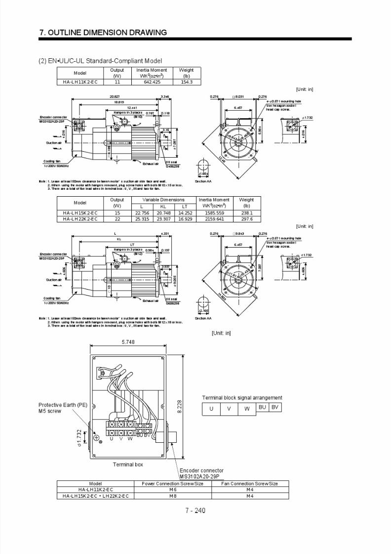
8/10/2019 Servo Motor - Instruction Manual SH(NA)-3181-D (03.00)
http://slidepdf.com/reader/full/servo-motor-instruction-manual-shna-3181-d-0300 319/368

8/10/2019 Servo Motor - Instruction Manual SH(NA)-3181-D (03.00)
http://slidepdf.com/reader/full/servo-motor-instruction-manual-shna-3181-d-0300 320/368
7 - 241
7. OUTLINE DIMENSION DRAWING
7.2.8 HC-AQ series
(1) Standard (without electromagnetic brake)Variable Dimensions (in)
ModelOutput
(W) LInertia Moment
WK2(oz•in 2)Weight
(lb)
HC-AQ0135D 10 2.126 0.027 0.419HC-AQ0235D 20 2.48 0.039 0.485HC-AQ0335D 30 2.756 0.051 0.551
0 . 8 2 7
4 5 °
0 . 0 2
A
A
0.394
0.63
0.098
L7.874 + 0.7870
1.043
MRRLG
WV
MRP5SD
UE
12
7
6
1
BC11340A
[Unit: in]
Arrow C
Power supply lead
Arrow C Section A-A
Connector 5557-12R-210(Molex make) UL94V-0
U: RedV: WhiteW: BlackEarth: Green
0.236
2- 0.114mounting hole
1 .2 9 9
1.102
0 . 7 8 7
0.2
(2) With electromagnetic brakeVariable Dimensions (in)
ModelOutput
(W) LInertia Moment
WK2(oz•in 2)Weight
(lb)
HC-AQ0135BD 10 3.228 0.04 0.639AC-AQ0235BD 20 3.504 0.052 0.705HC-AQ0335BD 30 3.78 0.064 0.772
1.102
0 . 8 2 7
4 5 °
0.63
0.098
L
1.043
MRRLG
B1WV
MRP5SDB2UE
12
7
6
1
A
A
0.394
0 . 0 2
BC11343A
[Unit: in]
Arrow C
Power supply lead/brake lead
Arrow C Section A-A
Connector 5557-12R-210(Molex make) UL94V-0
U: RedV: WhiteW: BlackEarth: GreenB1, B2
7.874 + 0.7870
1 .2 9 9 0
. 7 8 7
0.236
2- 0.114mounting hole
0.2

8/10/2019 Servo Motor - Instruction Manual SH(NA)-3181-D (03.00)
http://slidepdf.com/reader/full/servo-motor-instruction-manual-shna-3181-d-0300 321/368
7 - 242
7. OUTLINE DIMENSION DRAWING
7.2.9 HA-LF series
Terminal box detail diagram
Motor ModelHA-LF30K24
HA-LF37K24
HA-LF45K24HA-LF55K24
HA-LF30K2Motor power supplylead size
0.31in 2 2parallel
0.87in 2 2parallel
Motor power supplyterminal block screwsize
M8 M10
LA 8.661 10.472 Terminal boxdimensions(mm)
LB 8.268 9.055
LA
L B
BG71994B
Motor power supplylead
Encoder connector MS3102A20-29P
[Unit: in]
Motor power supplyterminal block(U, V, W)
Cooling fan terminal block(BU, BV, BW) M4 screw
Thermal protector terminal block(OHS1, OHS2) M4 screw
Earth terminalM5 screw
Cooling fan lead0.9SQ or equivalent
Thermal protector lead0.5SQ or equivalent
ModelOutput
(W)Inertia Moment
WK2(oz•in 2)Weight
(lb)H A-L F 30K 24 30 3007.095 352.739
0.236 0.23611.26
8.6610.433 1.063
5 . 9 8 4
23.819
5.039 16.772 5.512
5.512 7 . 0 4 7
4.134 4.134
10.236
4.252
2.008
4- 0.591
0 .984 0.19715.197
0.984 0.315
2 . 3 6 2
9 . 8 4 3
11.024
4 5 °
9 . 0 5 5
0 . 7 8 7
2.165
5
12.205
5
6 . 2 9 9
0 - 0 . 0 3 5
BC10833
[Unit: in]
Cooling fanrotation direction
Suction air
Encoder connector MS3102A20-29P
Hanger
(Note)Exhaust air
Oil seal S659013B
M12 screw
4- 0.748Use hexagon sockethead cap screw.
Note: When the motor is used without the hanger, plug the threaded hole with a bolt of M16 20mm or less.
1 1. 8 1
1

8/10/2019 Servo Motor - Instruction Manual SH(NA)-3181-D (03.00)
http://slidepdf.com/reader/full/servo-motor-instruction-manual-shna-3181-d-0300 322/368
7 - 243
7. OUTLINE DIMENSION DRAWING
ModelOutput
(W)Inertia Moment
WK2(oz•in 2)Weight
(lb)HA-L F37K 24 37 3553.84 396.832
0.236 0.23611.26
8.6610.433 1.063
5 . 9 8 7
25.591
5.039 18.543 5.512
5.512 7 . 0 4 7
5 5
11.969
4.252
2.008
4- 0.591
0 .984 0.197
16.969
0.984 0.315
2 . 3 6 2
0 . 8 4 3
11.024
4 5 °
9 . 0 5 5
0 . 7 8 7
2.165
512.205
5
6 . 2 9 9
0 - 0 . 0 3 5
BC10788C
[Unit: in]
Cooling fanrotation direction
Suction air
Encoder connector MS3102A20-29P
Hanger (Note)
Exhaust air
Oil seal S659013B
M12 screw
4- 0.748Use hexagon sockethead cap screw.
Note: When the motor is used without the hanger, plug the threaded hole with a bolt of M16 20mm or less.
1 1. 8 1
1
ModelOutput
(W)Inertia Moment
WK2(oz•in 2)Weight
(lb)H A-L F45K 24 45 5904.841 507.063
0.236 0.23613.858
10.4720.433 1.063
7 . 2 4 4
25.197
5.433 17.283 5.512
5.512
8 . 5 0 4
3.996 3.996
10.315
4.764
2.48
4- 0.748
0.9840.197
15.709
1.181 0.354
1 1 . 8 1 1
4 5 °
1 1 . 0 2 4
0 . 8 6 6
5.492
13.74
5.492
7 . 0 8 7 0 - 0 .
0 2
BC11107A
[Unit: in]
Cooling fanrotationdirection Suction air
Encoder connector
MS3102A20-29PHanger
(Note)Exhaust air
Oil seal S709513B
M16 screw
4- 0.748Use hexagon sockethead cap screw.
Note: When the motor is used without the hanger, plug the threaded hole with a bolt of M16 20mm or less.
2 . 5 5 9
2.756
1 3. 7 8
13.78

8/10/2019 Servo Motor - Instruction Manual SH(NA)-3181-D (03.00)
http://slidepdf.com/reader/full/servo-motor-instruction-manual-shna-3181-d-0300 323/368
7 - 244
7. OUTLINE DIMENSION DRAWING
ModelOutput
(W)Inertia Moment
WK2(oz•in 2)Weight
(lb)HA-L F55K 24 55 7162.354 551.155
0.236 0.23613.858
10.4720.433 1.063
7 . 2 4 4
26.969
5.433 19.055 5.512
5.512
8 . 5 0 4
4.744 4.744
11.811
4.764
2.48
4- 0.748
0.984 0.197
17.48
1.181 0.354
2 . 5 5 9
1 1 . 8 1 1
13.78
4 5 °
1 1 . 0 2 4
0 . 8 6 6
2.7565.492
13.74
5.492
7 . 0 8 7 0 - 0 .
0 2
BC10522F
1 3. 7 8
Cooling fanrotation
direction
Suction air
Encoder connector MS3102A20-29P
Hanger
(Note)Exhaust air
Oil seal S709513B
M16 screw
4- 0.748Use hexagon sockethead cap screw.
Note: When the motor is used without the hanger, plug the threaded hole with a bolt of M16 20mm or less.
[Unit: in]
ModelOutput
(W)Inertia Moment
WK2(oz•in 2)Weight
(lb)H A-L F30K 2 30 3007.095 352.739
BC12180Note: When the motor is used without the hanger, plug the threaded hole with a bolt of M16 20mm or less.
0.236 0.23611.26
10.472 1.063
Cooling fanrotation
direction Suction air 6 . 2 9 9
24.213
5.433 16.575
5.512
5.512 7 . 5 5 9
4.134 4.134
8.11
4.252
0.984 0.197
15
0.985 0.315
Encoder connector MS3102A20-29P Hanger
(Note)
Exhaust air
Oil seal S659013B
M12 screw
2.48
2 . 3 6 2
9 . 8 5 3
4- 0.591
4 5 °
1 0 . 2 3 6
0 . 7 8 7
2.165
5
12.205
5
6 . 2 9 9 0 - 0 0 .
2
4- 0.748Use hexagon socket
head cap screw.
1 1. 8 1
1
11.024
1 3 .7 8
0.433
[Unit: in]

8/10/2019 Servo Motor - Instruction Manual SH(NA)-3181-D (03.00)
http://slidepdf.com/reader/full/servo-motor-instruction-manual-shna-3181-d-0300 324/368
7 - 245
7. OUTLINE DIMENTION DRAWING
7.2.10 HC-MFS•HC-KFS Series
(1) Standard (without electromagnetic brake, without reduction gear)Variable Dimensions(in)
ModelOutput
(W) L KLInertia Moment
WK2(oz•in 2)Weight
(lb)
HC-MFS053 50 3.21 1.16 0.10 0.9HC-MFS13 100 3.80 0.18 0.16 1.2HC-KFS053 50 3.21 0.12 0.29 0.9HC-KFS13 100 3.80 1.75 0.46 1.2
Power supplyconnector pinconnection list
123
4
Pin No.
RedWhiteBlackGreen/yellow
Application
Phase UPhase VPhase W
Earth
Lead wirecolor
[Unit: in]
BC11873(BC11879 )
0.787
5557-04R-210 (Receptacle)5556PBTL (Female terminal)
With connector 1-172169-9(AMP maker)
Arrow A
4 5 °
1 . 4 0 6
Bottom
Top
Protective tube
Motor plate(Opposite side)
1 . 1 8 1
1 .8 1 1
1.575
Logo plate
Power supply connector (Molex make)
Encoder cable 11.8in
Motor plate
Caution plate
Bottom
TopBottom
Top
KL
0.984
0.0980.197
L
1.594
0.268
0.3900.992
1.654
1 . 1 3 0
2- 0.177
Power supply lead 4-AWG19 11.8in
TUV plate
Arrow A
Bottom
TopTop
Bottom
12
34
0 . 3 1 5
Variable Dimensions(in)Model
Output(W) L KL
Inertia MomentWK2(oz•in 2)
Weight(lb)
HC-MFS23 200 3.92 1.93 0.48 2.2HC-MFS43 400 4.90 0.06 0.78 3.2HC-MFS23 200 3.92 1.93 2.30 2.2HC-MFS43 400 4.90 0.06 3.66 3.2
Power supplyconnector pinconnection list
123
4
Pin No.
RedWhiteBlackGreen/yellow
Application
Phase UPhase VPhase W
Earth
Lead wirecolor
[Unit: in]
BC11874(BC11880 )
0.787
5557-04R-210 (Receptacle)5556PBTL (Female terminal)
With connector 1-172169-9(AMP maker)
Arrow A
4 5 °
1 . 6 8 5
Bottom
Top
Protective tube
Motor plate(Opposite side)
1 . 9 6 9
2 .7 5 6
2.362
0 . 5 5 1
Logo plate
Power supply connector (Molex make)
Encoder cable 11.8in
Motor plate
Caution plate
Bottom
Top
KL
1.1810.1180.276
L
1.614
0.417 0.3900.992
2.441
1 . 5 1 2
4- 0.228
Power supply lead 4-AWG19 11.8in
TUV plate
Arrow A
Top
Bottom
Top
Bottom
0.106
12
34

8/10/2019 Servo Motor - Instruction Manual SH(NA)-3181-D (03.00)
http://slidepdf.com/reader/full/servo-motor-instruction-manual-shna-3181-d-0300 325/368
7 - 246
7. OUTLINE DIMENSION DRAWING
ModelOutput
(W)Inertia Moment
WK2(oz•in 2)Weight
(lb)
HC-MFS73 750 3.28 6.6
Power supplyconnector pinconnection list
123
4
Pin No.
RedWhiteBlackGreen/yellow
Application
Phase UPhase VPhase W
Earth
Lead wirecolor
[Unit: in]
BC11875
0.787
5557-04R-210 (Receptacle)5556PBTL (Female terminal)
With connector 1-172169-9(AMP maker)
Arrow A
4 5 °
2 . 2 8 7
Bottom
Top
Protective tube
Motor plate(Opposite side)
2 . 7 5 6
3 .5 4 3
3.150
0 . 7 4 8
Logo plate
Power supply connector (Molex make)
Encoder cable 11.8in
Motor plate
Caution plate
Bottom
Top
3.413
1.575
0.1180.315
5.591
1.535
0.4330.3900.992
3.228
1 . 9 1 7
4- 0.260
Power supply lead 4-AWG19 11.8in
TUV plate
Arrow A
Top
Bottom
TopBottom
0.106
12
34
(2) With electromagnetic brakeVariable Dimensions
ModelOutput
(W) L KL
Braking Force(oz•in)
Inertia MomentWK2(oz•in 2)
Weight(lb)
HC-MFS053B 50 4.31 1.16 45.32 0.12 1.7HC-MFS13B 100 4.90 1.75 45.32 0.18 2.0HC-KFS053B 50 4.31 1.16 45.32 0.31 1.7HC-KFS13B 100 4.90 1.75 45.32 0.48 2.0
Power supplyconnector pinconnection list
123
4
Pin No.
RedWhiteBlackGreen/yellow
Application
Phase UPhase VPhase W
Earth
Lead wirecolor
56
B1B2
[Unit: in]
BC11881(BC11887 )
0.787
5557-06R-210 (Receptacle)5556PBTL (Female terminal)
Arrow A
4 5 °
1 . 4 0 6
Bottom
Top
Protective tube
Motor plate(Opposite side)
1 . 1 8 1
1 .8 1 1
1.575
0 . 3 1 5
Logo plate
Power supply connector (Molex make)
Encoder cable 11.8in
Motor plate
Caution plate
Bottom
Top
Top KL
0.984
0.0980.197
L1.594
0.268
0.3900.992
1.654
1 . 1 3 0
2- 0.177
Power supply lead 4-AWG19 11.8in
TUV plate
Arrow A
Bottom
TopTop
Bottom
Brake lead2-0.3 11.8in2
Insulock
12
45
3 6
2.579
Bottom
With connector 1-172169-9(AMP maker)

8/10/2019 Servo Motor - Instruction Manual SH(NA)-3181-D (03.00)
http://slidepdf.com/reader/full/servo-motor-instruction-manual-shna-3181-d-0300 326/368
7 - 247
7. OUTLINE DIMENSION DRAWING
Variable Dimensions (in)Model
Output(W) L KL
Braking Force(oz•in)
Inertia MomentWK2(oz•in 2)
Weight(lb)
HC-MFS23B 200 5.18 1.93 184 0.74 3.5HC-MFS43B 400 6.16 2.84 184 1.04 4.6HC-KFS23B 200 5.18 1.93 184 2.57 3.5
HC-KFS43B 400 6.16 2.84 184 3.94 4.6
Power supplyconnector pinconnection list
12
34
Pin No.
RedWhite
BlackGreen/yellow
Application
Phase UPhase V
Phase WEarth
Lead wirecolor
56
B1B2
[Unit: in]
BC11882(BC11888 )
0.787
5557-06R-210 (Receptacle)5556PBTL (Female terminal)
With connector 1-172169-9(AMP maker) Arrow A
4 5 °
1 . 6 8 5
Bottom
Top
Protective tube
Motor plate(Opposite side)
1 . 9 6 9
2 .7 5 6
2.362
0 . 5 5 1
Logo plate
Power supply connector (Molex make)
Encoder cable 11.8in
Motor plate
Caution plate
Bottom
Top
KL
1.1810.1180.276
L
1.614
0.417
0.3900.992
2.441
1 . 5 1 2
4- 0.228
Power supply lead 4-AWG19 11.8in
TUV plate
Arrow A
Top
Bottom
Top
Bottom
0.106
2.677
InsulockBrake lead2-0.3 11.8in2
1
2
4
5
3 6
ModelOutput
(W)Braking Force
(oz•in)Inertia Moment
KW2(oz•in 2)Weight
(lb)
HC-MFS73B 750 340 3.96 8.8
5557-06R-210 (Receptacle)5556PBTL (Female terminal)
Power supplyconnector pinconnection list
123
4
Pin No.
RedWhiteBlackGreen/yellow
Application
Phase UPhase VPhase W
Earth
Lead wirecolor
56
B1B2
[Unit: in]
BC11883
0.787
With connector 1-172169-9(AMP maker)
Arrow A
4 5 °
2 . 2 8 7
Bottom
Top
Protective tube
Motor plate(Opposite side)
2 . 7 5 6
3 .5 4 3
3.150
0 . 7 4 8
Logo plate
Power supply connector (Molex make)
Encoder cable 11.8in
otor plate
Caution plate
Bottom
Top
3.413
1.575
0.1180.315
6.988
1.535
0.4330.3900.992
3.228
1 . 9 1 7
4- 0.260
Power supply lead 4-AWG19 11.8in
TUV plate
Arrow A
Top
Bottom
TopBottom
0.106
2.835
Brake lead2-0.3 11.8in2
Insulock
1
2
4
5
3 6

8/10/2019 Servo Motor - Instruction Manual SH(NA)-3181-D (03.00)
http://slidepdf.com/reader/full/servo-motor-instruction-manual-shna-3181-d-0300 327/368
7 - 248
7. OUTLINE DIMENSION DRAWING
(3) With reduction gear for general industrial machine(a) Without electromagnetic brake
Variable Dimensions (in)Model
Output(W) L KL
ReductionGear Model
Reduction Ratio(Actual Reduction Ratio)
Inertia MomentWK2(oz•in 2)
BacklashWeight
(lb)
HC-MFS053G1 50 4.96 2.91 K6505 1/5(9/44) 0.30 60min. max. 3.1HC-MFS053G1 50 5.669 3.62 K 6512 1/12(49/576) 0.42 60min. max. 4.0HC-MFS053G1 50 5.669 3.62 K 6520 1/20(25/484) 0.32 60min. max. 4.0HC-KFS053G1 50 4.96 2.91 K6505 1/5(9/44) 0.49 60min. max. 3.1HC-K FS053G1 50 5.669 3.62 K 6512 1/12(49/576) 0.61 60min. max. 4.0HC-K FS053G1 50 5.669 3.62 K 6520 1/20(25/484) 0.51 60min. max. 4.0
Bottom
Power supplyconnector pinconnection list
123
4
Pin No.
RedWhiteBlackGreen/yellow
Application
Phase UPhase VPhase W
Earth
Lead wirecolor
[Unit: in]
BC11896(BC11924 )
0.787
5557-04R-210 (Receptacle)5556PBTL (Female terminal)
With connector 1-172169-9(AMP maker)
4 5 °
1 . 4 0 6
Bottom
Top
Protective tube
Motor plate(Opposite side)
2 . 3 6 2
2. 9 5 3
2.559
0 . 6 3 0
Logo plate
Power supply connector (Molex make)
Encoder cable 11.8in
Motor plate
Caution plate
Bottom
Top
KL
2.382
0.2560.315
L
1.594
0.268
0.3900.992
1.654
1 . 1 3 0
4- 0.276
Power supply lead 4-AWG19 11.8in
TUV plate
Arrow A
TopTop
Bottom
1.102 0.984
1 . 8 9 0 3. 4 6
5
For reverse rotation command
For forward rotation command"Rotation direction"
M4 threads,depth 0.315
Arrow A
1
2
3
4
Bottom
Top
Variable Dimensions (in)Model
Output(W) L KL
ReductionGear Model
Reduction Ratio(Actual Reduction Ratio)
Inertia MomentWK2(oz•in 2)
BacklashWeight
(lb)
HC-MFS13G1 100 5.551 3.5 K6505 1/5(9/44) 0.36 60min. max. 3.31HC-MFS13G1 100 6.26 4.21 K 6512 1/12(49/576) 0.48 60min. max. 4.19HC-MFS13G1 100 6.26 4.21 K 6520 1/20(25/484) 0.38 60min. max. 4.19HC-KFS13G1 100 5.551 3.5 K6505 1/5(9/44) 0.66 60min. max. 3.31HC-KFS13G1 100 6.26 4.21 K6512 1/12(49/576) 0.78 60min. max. 4.19HC-KFS13G1 100 6.26 4.21 K6520 1/20(25/484) 0.68 60min. max. 4.19
Bottom
Power supplyconnector pinconnection list
123
4
Pin No.
RedWhiteBlackGreen/yellow
Application
Phase UPhase VPhase W
Earth
Lead wirecolor
[Unit: in]
BC11897(BC11925 )
0.787
5557-04R-210 (Receptacle)5556PBTL (Female terminal)
With connector 1-172169-9(AMP maker) Arrow A
4 5 °
1 . 4 0 6
Bottom
Top
Protective tube
Motor plate(Opposite side)
2 . 3 6 2
2. 9 5 3
2.559
0 . 6 3 0
Logo plate
Power supply connector (Molex make)
Encoder cable 11.8in
Motor plate
Caution plate
Bottom
Top
KL
2.3820.2560.315
L
1.594
0.268
0.3900.992
1.654
1 . 1 3 0
4- 0.276
Power supply lead 4-AWG19 11.8in
TUV plate
Arrow A
TopTop
Bottom
1.102 0.984
1 . 8 9 0
3 .4 6 5
For reverse rotation command
For forward rotation command"Rotation direction"
M4 threads,depth 0.315
1
2
3
4
Bottom
Top

8/10/2019 Servo Motor - Instruction Manual SH(NA)-3181-D (03.00)
http://slidepdf.com/reader/full/servo-motor-instruction-manual-shna-3181-d-0300 328/368
7 - 249
7. OUTLINE DIMENSION DRAWING
Variable Dimensions (in)Model
Output(W) L KL
ReductionGear Model
Reduction Ratio(Actual Reduction Ratio)
Inertia MomentWK2(oz•in 2)
Weight(lb)
HC-MFS23G1 200 6.02 4.04 K9005 1/5(19/96) 1.36 7.3HC-MFS23G1 200 6.81 4.83 K9012 1/12(25/288) 1.60 8.6HC-MFS23G1 200 6.81 4.83 K9020 1/20(253/5000) 1.45 8.6
HC-KFS23G1 200 6.02 4.04 K9005 1/5(19/96) 3.17 7.3HC-KFS23G1 200 6.81 4.83 K9012 1/12(25/288) 3.44 8.6HC-KFS23G1 200 6.81 4.83 K9020 1/20(253/5000) 3.28 8.6
Power supplyconnector pinconnection list
123
4
Pin No.
RedWhiteBlackGreen/yellow
Application
Phase UPhase VPhase W
Earth
Lead wirecolor
[Unit: in]
BC11898(BC11926 )
0.787
5557-04R-210 (Receptacle)5556PBTL (Female terminal)With connector 1-172169-9
(AMP maker)
Arrow A
4 5 °
Protective tube
Motor plate(Opposite side)
3.543
0 . 9 8 4
Logo plate
Power supply connector (Molex make)Encoder cable 11.8in
Motor plate
Cautionplate
Bottom
Top
Bottom
Top
KL
2.9130.3150.394
L
0.4170.992
2.441
1 . 5 1 2
Power supply lead 4-AWG19 11.8in
Arrow A
Bottom
TUV plate
BottomTop
Top
1 . 6 8 5
0.390
0.106
1.6141.181 1.378
2 . 8 7 4
3 . 2 2 8
1
2
3
4
For reverse rotation command
For forward rotation command"Rotation direction"
4. 4 8 8 3. 9 3
7
4- 0.354
M6 threads,depth 0.472
Variable Dimensions (in)Model
Output(W) L KL
ReductionGear Model
Reduction Ratio(Actual Reduction Ratio)
Inertia MomentWK2(oz•in 2)
Weight(lb)
HC-MFS43G1 400 7.01 4.95 K9005 1/5(19/96) 1.62 8.4HC-MFS43G1 400 7.80 5.73 K9012 1/12(25/288) 1.85 9.7HC-KFS43G1 400 7.01 4.95 K9005 1/5(19/96) 4.48 8.4HC-KFS43G1 400 7.80 5.73 K9012 1/12(25/288) 4.76 9.7
Power supplyconnector pinconnection list
123
4
Pin No.
RedWhiteBlackGreen/yellow
Application
Phase UPhase VPhase W
Earth
Lead wirecolor
[Unit: in]
BC11899(BC11927 )
0.787
5557-04R-210 (Receptacle)5556PBTL (Female terminal)With connector 1-172169-9
(AMP maker)
Arrow A
4 5 °
Protective tube
Motor plate(Opposite side)
3.543
0 . 9 8 4
Logo plate
Power supply connector (Molex make)Encoder cable 11.8in
Motor plate
Cautionplate
Bottom
Top
Bottom
Top
KL
2.913
0.3150.394
L
0.4170.992
2.441
1 . 5 1 2
Power supply lead 4-AWG19 11.8in
Arrow A
Bottom
TUV plate
BottomTop
Top
1 . 6 8 5
0.390
0.106
1.614 1.181 1.378
2 . 8 7 4
3 . 2 2 8
1
2
3
4
For reverse rotation command
For forward rotation command"Rotation direction"
4 . 4 8 8 3. 9 3
7
4- 0.354
M6 threads,depth 0.472

8/10/2019 Servo Motor - Instruction Manual SH(NA)-3181-D (03.00)
http://slidepdf.com/reader/full/servo-motor-instruction-manual-shna-3181-d-0300 329/368
7 - 250
7. OUTLINE DIMENSION DRAWING
Reduction RatioModel
Output(W)
Reduction Gear Model Normal Reduction ratio Actual Reduction Ratio
Inertia MomentWK2(oz•in 2)
BacklashWeight
(lb)
HC-MFS43G1 400 K10020 1/20 253/5000 3.57 60min. max. 12.13HC-MFS73G1 750 K10005 1/5 1/5 5.58 60min. max. 13.67HC-MFS73G1 750 K10012 1/12 525/6048 9.22 60min. max. 16.09
HC-MFS73G1 750 K12020 1/20 625/12544 9.57 60min. max. 22.27
Variable Dimensions (in)Model
Output
(W) D LH LK LT H LA LB LC LD LE LF LG LM LN LP L LR KL LZ Q S P R
(Reduction
Ratio)
HC-MF S43G1 400 2.362 1.50 1.61 0.42 1.69 4.53 3.74 5.20 3.94 0.39 2.87 0.39 0.512 0.63 3.39 7.933 3.54 5.87 0.35 1.97 1.26 M8 0.63 1/20
HC-MF S73G1 750 3.15 1.89 1.54 0.43 2.29 4.53 3.74 5.20 3.94 0.39 2.87 0.39 0.512 0.63 3.39 8.15 3.54 5.97 0.35 1.97 1.26 M8 0.63 1/5
HC-MF S73G1 750 3.15 1.89 1.54 0.43 2.29 4.53 3.74 5.20 3.94 0.39 2.87 0.39 0.512 0.63 3.39 9.016 3.54 6.84 0.35 1.97 1.26 M8 0.63 1/12
HC-MF S73G1 750 3.15 1.89 1.54 0.43 2.29 5.51 4.53 6.38 4.72 0.47 3.54 0.59 0.512 0.787 4.09 9.528 4.17 7.35 0.55 2.36 1.57 M10 0.79 1/20
Power supplyconnector pinconnection list
123
4
Pin No.
RedWhiteBlackGreen/yellow
Application
Phase UPhase VPhase W
Earth
Lead wirecolor
[Unit: in]
BC11900
0.787
5557-04R-210 (Receptacle)5556PBTL (Female terminal)
With connector 1-172169-9(AMP maker) Arrow A
4 5 °
Protective tube
Motor plate(Opposite side)
LD
S h 6
Logo plate
Power supply connector (Molex make)
Encoder cable 11.8in
Motor plate
Cautionplate
BottomTop
Bottom
Top
KL
LRL
LT0.992
D
Power supply lead 4-AWG19 11.8in
Arrow A
TUV plate
Bottom
Top
0.390
0.106LK
LG
L F
1
2
3
4
For reverse rotation command
For forward rotation command
"Rotation direction"
L C L A
4- LZ
P threads,depth R
BottomTop
L H
H
LE
LM LN Q
L P L B h 7
Reduction RatioModel
Output(W)
Reduction Gear Model Normal Reduction ratio Actual Reduction Ratio
Inertia MomentWK2(oz•in 2)
BacklashWeight
(lb)
HC-K FS43G1 400 K 10020 1/20 253/5000 6.45 60min. max. 12.13
Power supplyconnector pinconnection list
123
4
Pin No.
RedWhiteBlackGreen/yellow
Application
Phase UPhase VPhase W
Earth
Lead wirecolor
[Unit: in]
0.787
5557-04R-210 (Receptacle)5556PBTL (Female terminal)
With connector 1-172169-9(AMP maker) Arrow A
4 5 °
Protective tube
Motor plate(Opposite side)
3.937Logo plate
Power supply connector (Molex make)
Encoder cable 11.8in
Motor plate
Cautionplate
BottomTop
BottomTop
5.870
3.5437.933
0.4170.992
2.441
Power supply lead 4-AWG19 11.8in
Arrow A
TUV plate
Bottom
Top
0.390
0.106
1.614
0.394
2 . 8 7 4
1
2
3
4
For reverse rotation command
For forward rotation command
"Rotation direction"
4- 0.354
M8 threads,depth 0.630
BottomTop
1 . 5 1 2
1 . 6 8 5
0.394
0.630 1.969
3 . 3 8 6
3 . 7 4 0
1 . 2 6 0
0.512
4 . 5 2 8
5. 1 9 7

8/10/2019 Servo Motor - Instruction Manual SH(NA)-3181-D (03.00)
http://slidepdf.com/reader/full/servo-motor-instruction-manual-shna-3181-d-0300 330/368
7 - 251
7. OUTLINE DIMENSION DRAWING
(2) With electromagnetic brakeVariable Dimensions (in)
ModelOutput
(W) L KLBraking Force
(oz•in)Reduction
Gear ModelReduction
RatioInertia Moment
WK2(oz•in 2)Backlash
Weight(lb)
HC-MFS053BG1 50 6.06 2.91 45 K6505 1/5(9/44) 0.32 60min. max. 4.0HC-MFS053BG1 50 6.77 3.62 45 K 6512 1/12(49/576) 0.44 60min. max. 4.9HC-MFS053BG1 50 6.77 3.62 45 K 6520 1/20(25/484) 0.34 60min. max. 4.9HC-KFS053BG1 50 6.02 2.91 45 K6505 1/5(9/44) 0.51 60min. max. 4.0HC-K FS053BG1 50 6.77 3.62 45 K 6512 1/12(49/576) 0.63 60min. max. 4.9HC-K FS053BG1 50 6.77 3.62 45 K 6520 1/20(25/484) 0.53 60min. max. 4.9
Power supplyconnector pinconnection list
123
4
Pin No.
RedWhiteBlackGreen/yellow
Application
Phase UPhase VPhase W
Earth
Lead wirecolor
56
B1B2
BC11901(BC11929 )
[Unit: in]
0.787
5557-06R-210 (Receptacle)5556PBTL (Female terminal)
With connector 1-172169-9(AMP maker)
Arrow A
4 5 °
Protective tube
Motor plate(Opposite side)
2.559Logo plate
Power supply connector (Molex make)
Encoder cable 11.8in
Motor plate
Cautionplate
Top
Bottom
2.382L
0.268
0.992
1.654
Arrow A
TUV plate0.390
1.5940.315
1
2
4
5
For reverse rotation command
For forward rotation command
"Rotation direction"
3. 4 6 5 2. 9 5 3
4- 0.276
M4 threads,depth 0.315
Bottom
Top 1 . 1 3 0
0.256
1.102 0.984
1 . 8 9 0
2 . 3 6 2
0 . 6 3 0
Bottom
Top
2.579
Power supply lead 4-AWG19 11.8in
Brake lead2-0.3 11.8in2
Bottom
Top 1 . 4 0 6
Insulock
3 6
KL
TopBottom
Variable Dimensions (in)Model
Output(W) L KL
Braking Force(oz•in)
ReductionGear Model
ReductionRatio
Inertia MomentWK2(oz•in 2)
BacklashWeight
(lb)
HC-MFS13BG1 100 6.65 3.43 45 K6505 1/5(9/44) 0.38 60min. max. 4.2HC-MFS13BG1 100 7.36 4.21 45 K 6512 1/12(49/576) 0.50 60min. max. 5.1HC-MFS13BG1 100 7.36 4.21 45 K 6520 1/20(25/484) 0.40 60min. max. 5.1HC-KFS13BG1 100 6.65 3.43 45 K6505 1/5(9/44) 0.68 60min. max. 4.2HC-K FS13BG1 100 7.36 4.21 45 K 6512 1/12(49/576) 0.80 60min. max. 5.1HC-KFS13BG1 100 7.36 4.21 45 K6520 1/20(25/484) 0.7 60min. max. 5.1
Power supplyconnector pinconnection list
123
4
Pin No.
RedWhiteBlackGreen/yellow
Application
Phase UPhase VPhase W
Earth
Lead wirecolor
5
6
B1B2
BC11902(BC11930 )
[Unit: in]
0.787
5557-06R-210 (Receptacle)5556PBTL (Female terminal)
With connector 1-172169-9(AMP maker)
Arrow A
4 5 °
Protective tube
Motor plate(Opposite side)
2.559
Logo plate
Power supply connector (Molex make)
Encoder cable 11.8in
Motor plate
Cautionplate
Top
Bottom
2.382L
0.268
0.992
1.654
Arrow A
TUV plate 0.390
1.5940.315
1
2
4
5
For reverse rotation command
For forward rotation command
"Rotation direction"
3 .4 6 5 2. 9 5
3
4- 0.276
M4 threads,depth 0.315
Bottom
Top 1 . 1 3 0
0.256
1.102 0.984
1 . 8 9 0
2 . 3 6 2
0 . 6 3 0
Bottom
Top
2.579
Power supply lead 4-AWG19 11.8in
Brake lead2-0.3 11.8in2
Bottom
Top 1 . 4 0 6
Insulock
3 6
KL
TopBottom

8/10/2019 Servo Motor - Instruction Manual SH(NA)-3181-D (03.00)
http://slidepdf.com/reader/full/servo-motor-instruction-manual-shna-3181-d-0300 331/368
7 - 252
7. OUTLINE DIMENSION DRAWING
Variable Dimensions (in)Model
Output(W) L KL
ReductionGear Model
Reduction Ratio(Actual Reduction Ratio)
Inertia MomentWK2(oz•in 2)
Weight(lb)
HC-MFS23BG1 200 6.65 4.04 K9005 1/5(19/96) 1.58 8.6HC-MFS23BG1 200 7.36 4.23 K9012 1/12(25/288) 1.82 9.9HC-MFS23BG1 200 7.36 4.23 K9020 1/20(253/5000) 1.67 9.9
HC-KFS23BG1 200 6.65 4.04 K9005 1/5(19/96) 3.44 8.6HC-KFS23BG1 200 7.36 4.23 K9012 1/12(25/288) 3.72 9.9HC-KFS23BG1 200 7.36 4.23 K9020 1/20(253/5000) 3.55 9.9
Power supplyconnector pinconnection list
123
4
Pin No.
RedWhiteBlackGreen/yellow
Application
Phase UPhase VPhase W
Earth
Lead wirecolor
56
B1B2
BC11903(BC11931 )
[Unit: in]
0.787
5557-06R-210 (Receptacle)5556PBTL (Female terminal)With connector 1-172169-9
(AMP maker) Arrow A
4 5 °
Protective tube
Motor plate(Opposite side)
3.543
Logo plate
Power supply connector (Molex make)Encoder cable 11.8in
Motor plate
Cautionplate
Bottom
Top
Bottom
Top
2.992L
0.4170.992
2.441
Arrow A
TUV plate
0.390
1.6140.394
1
2
4
5
For reverse rotation command
For forward rotation command"Rotation direction"
4 .4 8 8 3. 9 3
7
4- 0.354
M6 threads,depth 0.472
1 . 5 1 2
0.315
1.181 1.378
2 . 8 7 4
3 . 2 2 8
0 . 9 8 4
Bottom
Top
2.677
Power supply lead 4-AWG19 11.8in
Brake lead2-0.3 11.8in2
Insulock
3 6
KL
0.106
1 . 6 8 5
Top
Bottom
Variable Dimensions (in)Model
Output(W) L KL
Braking Force(oz•in)
ReductionGear Model
Reduction Ratio(Actual Reduction Ratio)
Inertia MomentWK2(oz•in 2)
Weight(lb)
HC-MFS43BG1 400 8.27 4.95 184 K9005 1/5(19/96) 1.88 9.7HC-MFS43BG1 400 9.06 5.73 184 K9012 1/12(25/288) 2.12 11.0HC-KFS43BG1 400 8.27 4.95 184 K9005 1/5(19/96) 4.76 9.7HC-KFS43BG1 400 9.06 5.73 184 K9012 1/12(25/288) 5.03 11.0
Power supplyconnector pinconnection list
123
4
Pin No.Red
WhiteBlackGreen/yellow
ApplicationPhase UPhase VPhase W
Earth
Lead wirecolor
56
B1B2
BC11904(BC11932 )
[Unit: in]
0.787
5557-06R-210 (Receptacle)5556PBTL (Female terminal)With connector 1-172169-9
(AMP maker) Arrow A
4 5 °
Protective tube
Motor plate(Opposite side)
3.543Logo plate
Power supply connector (Molex make)Encoder cable 11.8in
Motor plate
Cautionplate
Bottom
Top
Bottom
Top
2.913L
0.4170.992
2.441
Arrow A
TUV plate
0.390
1.614 0.394
1
2
4
5
For reverse rotation command
For forward rotation command
"Rotation direction"
4 .4 8 8 3. 9 3
7
4- 0.354
M6 threads,depth 0.472
1 . 5 1 2
0.3151.181 1.378
2 . 8 7 4
3 . 2 2 8
0 . 9 8 4Bottom
Top
2.677
Power supply lead 4-AWG19 11.8in
Brake lead2-0.3 11.8in2
Insulock
3 6
KL
0.106
1 . 6 8 5
Bottom
Top

8/10/2019 Servo Motor - Instruction Manual SH(NA)-3181-D (03.00)
http://slidepdf.com/reader/full/servo-motor-instruction-manual-shna-3181-d-0300 332/368
7 - 253
7. OUTLINE DIMENSION DRAWING
Reduction RatioModel
Output(W)
Brake Force(oz•in)
ReductionGear Model Normal Reduction ratio Actual Reduction Ratio
Inertia MomentWK2(oz•in 2)
BacklashWeight
(lb)
HC-MFS43BG1 400 184 K10020 1/20 253/5000 3.83 60min. max. 13.4HC-MFS73BG1 750 340 K10005 1/5 1/5 6.26 60min. max. 15.9HC-MFS73BG1 750 340 K10012 1/12 525/6048 9.90 60min. max. 18.3
HC-MFS73BG1 750 340 K12020 1/20 625/12544 10.25 60min. max. 25.8
Variable Dimensions (in)Model
Output
(W) D LH LK LT LX H LA LB LC LD LE LF LG LM LN LP L LR KL LZ Q S P R
(Reduction
Ratio)
HC-MF S43BG1 400 2.44 1.51 1.64 0.14 2.68 1.69 4.53 3.74 5.20 3.94 0.39 2.87 0.39 0.512 0.63 3.39 9.19 3.54 5.87 0.35 1.97 1.26 M 8 0.63 1/20
HC-MF S73BG1 750 3.23 1.92 1.54 0.43 2.84 1.69 4.53 3.74 5.20 3.94 0.39 2.87 0.39 0.512 0.63 3.39 9.55 3.54 5.92 0.35 1.97 1.26 M8 0.63 1/5
HC-MF S73BG1 750 3.23 1.92 1.54 0.43 2.84 1.69 4.53 3.74 5.20 3.94 0.39 2.87 0.39 0.512 0.63 3.39 10.41 3.54 6.84 0.35 1.97 1.26 M8 0.63 1/12
HC-MF S73BG1 750 3.23 1.92 1.54 0.43 2.84 1.69 5.51 4.53 6.38 4.72 0.47 3.54 0.59 0.512 0.787 4.09 10.93 4.17 7.35 0.55 2.36 1.57 M10 0.79 1/20
Power supplyconnector pinconnection list
123
4
Pin No.
RedWhiteBlackGreen/yellow
Application
Phase UPhase VPhase W
Earth
Lead wirecolor
56
B1B2
BC11905
[Unit: in]
0.787
5557-06R-210 (Receptacle)5556PBTL (Female terminal)
With connector 1-172169-9(AMP maker)
Arrow A
4 5 °
Protective tube
Motor plate(Opposite side)
LDLogo plate
Power supply connector (Molex make)Encoder cable 11.8in
Motor plate
Cautionplate
Bottom
Top
Bottom
Top
LRL
LT0.992
D
Arrow A
TUV plate
0.390
LKLG
1
2
4
5
For reverse rotation command
For forward rotation command
"Rotation direction"
L A
L C
4- LZ
P threads,depth R
L H
LELN Q
L F L B h 7 S
h 6Bottom
Top
LX
Power supply lead 4-AWG19 11.8in
Brake lead2-0.3 11.8in2
Insulock
3 6
KL
0.106
H
Bottom
Top
LM
L P
Reduction RatioModel
Output(W)
Brake Force(oz•in)
ReductionGear Model
NormalReduction ratio
ActualReduction Ratio
Inertia MomentWK2(oz•in 2)
BacklashWeight
(lb)
HC-KFS43BG1 400 184 K10020 1/20 253/5000 6.73 60min. max. 13.4
Power supplyconnector pinconnection list
123
4
Pin No.
RedWhiteBlackGreen/yellow
Application
Phase UPhase VPhase W
Earth
Lead wirecolor
56
B1B2
[Unit: in]
0.787
5557-06R-210 (Receptacle)5556PBTL (Female terminal)
With connector 1-172169-9(AMP maker)
Arrow A
4 5 °
Protective tube
Motor plate(Opposite side)
3.937Logo plate
Power supply connector (Molex make)Encoder cable 11.8in
Motor plate
Cautionplate
Bottom
Top
Bottom
Top
3.5439.193
0.4170.992
2.441
Arrow A
TUV plate
0.390
1.6140.394
1
2
4
5
For reverse rotation command
For forward rotation command"Rotation direction"
4- 0.354
M8 threads,depth 0.630
1 . 5 1 2
0.394
0.630 1.969
2 . 8 7 4
3 . 7 4 0
1 . 2 6 0
Bottom
Top
2.677
Power supply lead 4-AWG19 11.8in
Brake lead2-0.3 11.8in2
Insulock
3 6
5.870
0.106
1 . 6 8 5
Bottom
Top
3 . 3 8 6
4 . 5 2 8
5. 1 9 7
0.512

8/10/2019 Servo Motor - Instruction Manual SH(NA)-3181-D (03.00)
http://slidepdf.com/reader/full/servo-motor-instruction-manual-shna-3181-d-0300 333/368
7 - 254
7. OUTLINE DIMENSION DRAWING
(4) With reduction gear for precision application(a) Without electromagnetic brake
Variable Dimensions (in)Model
Output(W) L KL
Reduction Gear Model
Reduction RatioInertia Moment
WK2(oz•in 2)Backlash
Weight(lb)
HC-MFS053G2 50 5.12 3.07 BK1-05B-A5MEKA 1/5 0.36 3 min. max. 3.1HC-MFS053G2 50 5.75 3.70 BK1-09B-A5MEKA 1/9 0.33 3 min. max. 3.7HC-MFS053G2 50 5.75 3.70 BK1-20B-A5MEKA 1/20 0.38 3 min. max. 4.0HC-MFS053G2 50 5.75 3.70 BK1-29B-A5MEKA 1/29 0.31 3 min. max. 4.0HC-KFS053G2 50 5.12 3.07 BK1-05B-A5MEKA 1/5 0.55 3 min. max. 3.1HC-KFS053G2 50 5.75 3.70 BK1-09B-A5MEKA 1/9 0.52 3 min. max. 3.7HC-KFS053G2 50 5.75 3.70 BK1-20B-A5MEKA 1/20 0.57 3 min. max. 4.0HC-KFS053G2 50 5.75 3.70 BK1-29B-A5MEKA 1/29 0.50 3 min. max. 4.0
Power supplyconnector pinconnection list
123
4
Pin No.
RedWhiteBlackGreen/yellow
Application
Phase UPhase VPhase W
Earth
Lead wirecolor
[Unit: in]
BC11906(BC11916 )
Logo plate
Motor plate
With connector 1-172169-9(AMP maker)
Encoder cable11.8in
Motor plate(Opposite side)
0.3152.382L
1.5940.256
0.906
0.268
KL0.992
Top 1 . 1 3 0
Bottom
Top
TUV plateCaution plate
Top
Bottom Bottom
1.654
For reverse rotation command
For forward rotation commandRotation direction
2.756
M4 threads, depth0.315
0.787
1 3
2 4
Arrow A
4 - 0.260
Top
Bottom
1 . 4 0 6
4 5 °
5557-04R-210 (Receptacle)5556PBTL (Female terminal)
Power supply connector (Molex make)
Protective tube
Power supply lead 4-AWG1911.8in
Arrow A
0.390
0.984
1 . 8 9 0
2 . 5 5 9
2 . 3 6 2
0 . 6 3 0
3. 1 5 0
3. 7 4 0
Bottom
Top

8/10/2019 Servo Motor - Instruction Manual SH(NA)-3181-D (03.00)
http://slidepdf.com/reader/full/servo-motor-instruction-manual-shna-3181-d-0300 334/368
7 - 255
7. OUTLINE DIMENSION DRAWING
ModelOutput
(W)Reduction Gear
ModelReduction Ratio
Inertia MomentWK2(oz•in 2)
BacklashWeight
(lb)
HC-MFS13G2 100 BK 1-05B-01MEK A 1/5 0.43 3 min. max. 3.3HC-MFS13G2 100 BK 1-09B-01MEK A 1/9 0.39 3 min. max. 4.0HC-MF S13G2 100 B K2-20B-01ME KA 1/20 0.66 3 min. max. 6.6
HC-MF S13G2 100 B K2-29B-01ME KA 1/29 0.52 3 min. max. 6.6
Variable DimensionsModel
Output(W) LA LB LC LD LE LF LG LH LK L LR KL LZ Q S P R
(ReductionRatio)
HC-MFS13G2 100 3.15 2.56 3.74 2.76 0.24 1.89 0.31 2.362 0.906 5.71 2.17 3.66 0.26 0.98 0.63 M4 0.31 1/5HC-MFS13G2 100 3.15 2.56 3.74 2.76 0.24 1.89 0.31 2.362 0.906 6.34 2.17 4.29 0.26 0.98 0.63 M4 0.31 1/9HC-MFS13G2 100 3.94 3.15 4.53 3.35 0.24 2.559 0.39 2.913 1.299 6.57 2.95 4.53 0.26 1.38 0.79 M5 0.39 1/20HC-MFS13G2 100 3.94 3.15 4.53 3.35 0.24 2.559 0.39 2.913 1.299 6.57 2.95 4.53 0.26 1.38 0.79 M5 0.39 1/29
ModelOutput
(W)Reduction Gear
ModelReduction Ratio
Inertia MomentWK2(oz•in 2)
BacklashWeight
(lb)
HC-K FS13G2 100 BK 1-05B-01MEK A 1/5 0.72 3 min. max. 3.3HC-K FS13G2 100 BK 1-09B-01MEK A 1/9 0.69 3 min. max. 4.0HC-K FS13G2 100 BK 2-20B-01MEK A 1/20 0.96 3 min. max. 6.6HC-K FS13G2 100 BK 2-29B-01MEK A 1/29 0.82 3 min. max. 6.6
Variable DimensionsModel
Output(W) LA LB LC LD LE LF LG LH LK L LR KL LZ Q S P R
(ReductionRatio)
HC-KFS13G2 100 3.15 2.56 3.74 2.76 0.24 1.89 0.31 2.362 0.906 5.71 2.17 3.66 0.26 0.98 0.63 M4 0.31 1/5HC-KFS13G2 100 3.15 2.56 3.74 2.76 0.24 1.89 0.31 2.362 0.906 6.34 2.17 4.29 0.26 0.98 0.63 M4 0.31 1/9HC-KFS13G2 100 3.94 3.15 4.53 3.35 0.24 2.559 0.39 2.913 1.299 6.57 2.95 4.53 0.26 1.38 0.79 M5 0.39 1/20HC-KFS13G2 100 3.94 3.15 4.53 3.35 0.24 2.559 0.39 2.913 1.299 6.57 2.95 4.53 0.26 1.38 0.79 M5 0.39 1/29
Power supplyconnector pinconnection list
123
4
Pin No.
RedWhiteBlackGreen/yellow
Application
Phase UPhase VPhase W
Earth
Lead wirecolor
[Unit: in]
BC11907(BC11917 )
Logo plate
Motor plate
With connector 1-172169-9(AMP maker)
Encoder cable 11.8in
Motor plate
(Opposite side)
LG
LRL
LE
LK Q
KL
Top
Bottom
Top
TUV plateCaution plate
Top
For reverse rotation command
For forward rotation commandRotation direction
LD
L A
P threads, depthR
S h 6
L F L B h 7
0.787
1 32 4
Arrow A
4 - LZ
Bottom L C
1 . 4 0 6
4 5 °
5557-04R-210 (Receptacle)5556PBTL (Female terminal)
Power supply connector (Molex make)
Protective tube
Power supply lead 4-AWG19 11.8in
Arrow A
L H
0.268
0.992
1 . 1
3 0
0.390
1.5941.654
Bottom BottomTop

8/10/2019 Servo Motor - Instruction Manual SH(NA)-3181-D (03.00)
http://slidepdf.com/reader/full/servo-motor-instruction-manual-shna-3181-d-0300 335/368
7 - 256
7. OUTLINE DIMENSION DRAWING
ModelOutput
(W)Reduction Gear
ModelReduction Ratio
Inertia MomentWK2(oz•in 2)
Weight(lb)
HC-MFS23G2 200 BK1-05B-02MEKA 1/5 1.04 4.6HC-MFS23G2 200 BK2-09B-02MEKA 1/9 1.14 7.7HC-MFS23G2 200 BK 3-20B-02MEKA 1/20 1.95 11.0
HC-MFS23G2 200 BK 3-29B-02MEKA 1/29 1.51 11.0
Variable Dimensions (in)Model
Output(W) LA LB LC LD LE LF LG LH LK L LR KL LZ Q S P R
(ReductionRatio)
HC-MFS23G2 200 3.15 2.56 3.74 2.76 0.24 1.89 0.31 2.362 0.906 6.18 2.17 4.20 0.26 0.98 0.63 M4 0.31 1/5HC-MFS23G2 200 3.94 3.15 4.53 3.35 0.24 2.559 0.39 2.913 1.299 6.89 2.95 4.91 0.26 1.38 0.79 M5 0.39 1/9HC-MFS23G2 200 4.53 3.74 5.31 3.94 0.31 2.953 0.39 3.346 1.378 7.09 3.35 5.10 0.35 1.57 0.98 M6 0.47 1/20HC-MFS23G2 200 4.53 3.74 5.31 3.94 0.31 2.953 0.39 3.346 1.378 7.09 3.35 5.10 0.35 1.57 0.98 M6 0.47 1/29
ModelOutput
(W)Reduction Gear
ModelReduction Ratio
Inertia MomentWK2(oz•in 2)
Weight(lb)
HC-KFS23G2 200 BK1-05B-02MEKA 1/5 2.84 4.6HC-KFS23G2 200 BK2-09B-02MEKA 1/9 2.95 7.7HC-K FS23G2 200 BK 3-20B-02MEK A 1/20 3.77 11.0HC-K FS23G2 200 BK 3-29B-02MEK A 1/29 3.34 11.0
Variable Dimensions (in)Model
Output(W) LA LB LC LD LE LF LG LH LK L LR KL LZ Q S P R
(ReductionRatio)
HC-KFS23G2 200 3.15 2.56 3.74 2.76 0.24 1.89 0.31 2.362 0.906 6.18 2.17 4.20 0.26 0.98 0.63 M4 0.31 1/5HC-KFS23G2 200 3.94 3.15 4.53 3.35 0.24 2.559 0.39 2.913 1.299 6.89 2.95 4.91 0.26 1.38 0.79 M5 0.39 1/9HC-KFS23G2 200 4.53 3.74 5.31 3.94 0.31 2.953 0.39 3.346 1.378 7.09 3.35 5.10 0.35 1.57 0.98 M6 0.47 1/20HC-KFS23G2 200 4.53 3.74 5.31 3.94 0.31 2.953 0.39 3.346 1.378 7.09 3.35 5.10 0.35 1.57 0.98 M6 0.47 1/29
Power supplyconnector pinconnection list
123
4
Pin No.
RedWhiteBlackGreen/yellow
Application
Phase UPhase VPhase W
Earth
Lead wirecolor
[Unit: in]
BC11908(BC11918 )
Logo plate
Motor plate
With connector 1-172169-9(AMP maker)
Encoder cable 11.8in
Motor plate(Opposite side)
LGLR
L
1.641 LELK Q
0.417KL0.992
1 . 5 1 2
Bottom
Top
TUV plate
Caution plate
Top
2.441
For reverse rotation command
For forward rotation commandRotation direction
LD
L A
P threads, depthR
S h 6
L F L B h 7
0.7871 3
2 4
Arrow A
4 - LZ
Top
Bottom L C
1 . 6 8 5
4 5 °
5557-04R-210 (Receptacle)5556PBTL (Female terminal)
Power supply connector (Molex make)
Protective tube
Power supply lead 4-AWG19 11.8in
L H
0.106
Arrow A
BottomTop
0.390
Bottom

8/10/2019 Servo Motor - Instruction Manual SH(NA)-3181-D (03.00)
http://slidepdf.com/reader/full/servo-motor-instruction-manual-shna-3181-d-0300 336/368

8/10/2019 Servo Motor - Instruction Manual SH(NA)-3181-D (03.00)
http://slidepdf.com/reader/full/servo-motor-instruction-manual-shna-3181-d-0300 337/368
7 - 258
7. OUTLINE DIMENSION DRAWING
ModelOutput
(W)Reduction Gear
ModelReduction Ratio
Inertia MomentWK2(oz•in 2)
Weight(lb)
HC-MFS73G2 750 BK 3-05B-08MEK A 1/5 5.32 13.89HC-MFS73G2 750 BK 4-09B-08MEK A 1/9 5.36 18.96HC-MFS73G2 750 BK 5-20B-08MEK A 1/20 5.55 26.46
HC-MFS73G2 750 BK 5-29B-08MEK A 1/29 4.97 26.46
Variable Dimensions (in)Model
Output(W) LA LB LC LD LE LF LG LH LK L LR KL LZ Q S P R
(ReductionRatio)
HC-MFS73G2 750 4.53 3.74 5.31 3.94 0.31 2.953 0.39 3.346 1.378 8.35 3.35 6.17 0.35 1.57 0.98 M6 0.47 1/5HC-MFS73G2 750 5.31 4.33 6.10 4.53 0.31 3.543 0.47 3.937 1.575 9.76 3.94 7.59 0.43 1.97 1.26 M8 0.63 1/9HC-MFS73G2 750 5.91 4.92 6.89 5.12 0.39 4.134 0.59 4.528 1.693 9.76 4.53 7.59 0.55 2.36 1.57 M10 0.79 1/20HC-MFS73G2 750 5.91 4.92 6.89 5.12 0.39 4.134 0.59 4.528 1.693 9.76 4.53 7.59 0.55 2.36 1.57 M10 0.79 1/29
Power supplyconnector pinconnection list
123
4
Pin No.
RedWhiteBlackGreen/yellow
Application
Phase UPhase VPhase W
Earth
Lead wirecolor
[Unit: in]
BC11910
Logo plate
Motor plate
With connector 1-172169-9(AMP maker)
Encoder cable11.8in
Motor plate(Opposite side)
LG
LRL
1.535 LE
LK Q
0.390 KL0.992
1 . 9 1 7
Bottom
Top
TUV plate
Caution plate
3.228
For reverse rotation command
For forward rotation commandRotation direction
LD
L A
P threads, depthR
S h 6
L F L B h 7
0.787
1 3
2 4
Arrow A
4 - LZ
TopBottom
L C
2 . 2 8 7
4 5 °
5557-04R-210 (Receptacle)5556PBTL (Female terminal)
Power supply connector (Molex make)
Protective tubePower supply lead 4-AWG1911.8in
L H
0.106
Arrow A
Bottom
Top
Bottom
Top0.433

8/10/2019 Servo Motor - Instruction Manual SH(NA)-3181-D (03.00)
http://slidepdf.com/reader/full/servo-motor-instruction-manual-shna-3181-d-0300 338/368
7 - 259
7. OUTLINE DIMENSION DRAWING
(b) With electromagnetic brakeVariable Dimensions (in)
ModelOutput
(W) L KLBraking Force
(oz•in)Reduction Gear
ModelReduction
RatioInertia Moment
WK2(oz•in 2)Backlash
Weight(lb)
HC-MFS053G2 50 6.22 3.07 45 BK1-05B-A5MEKA 1/5 0.38 3 min. max. 4.0HC-MFS053G2 50 6.85 3.70 45 BK1-09B-A5MEKA 1/9 0.34 3 min. max. 4.6HC-MFS053G2 50 6.85 3.70 45 BK1-20B-A5MEKA 1/20 0.39 3 min. max. 4.9HC-MFS053G2 50 6.85 3.70 45 BK1-29B-A5MEKA 1/29 0.33 3 min. max. 4.9HC-KFS053G2 50 6.22 3.07 45 BK1-05B-A5MEK A 1/5 0.57 3 min. max. 4.0HC-KFS053G2 50 6.85 3.70 45 BK1-09B-A5MEK A 1/9 0.54 3 min. max. 4.6HC-KFS053G2 50 6.85 3.70 45 BK1-20B-A5MEKA 1/20 0.59 3 min. max. 4.9HC-KFS053G2 50 6.85 3.70 45 BK1-29B-A5MEKA 1/29 0.52 3 min. max. 4.9
[Unit: in]
Logo plate
otor plate
With connector 1-172169-9(AMP maker)
Encoder cable 11.8in
Motor plate(Opposite side)
L
2.5790.390
KL
Top
BottomTop
TUV plateCaution plate
For reverse rotation command
For forward rotation commandRotation direction
2.756
1 4
2 5
Bottom
4 5 °
5557-06R-210 (Receptacle)5556PBTL (Female terminal)
Power supply connector (Molex make)
Protective tube
Power supply lead 4-AWG19 11.8in
Arrow A
Insulock
3 6
Arrow A
Break lead2-0.3 11.8in2
1.5941.654
0.268
0.992
1 . 1 3 0
4- 0.2600.315
2.382
0.2560.906 0.984
1 . 8 9 0
2 . 5 5 9
2 . 3 6 2
0 . 6 3 0
M4 threads, depth 0.315
0.787
1 . 4
0 6
3. 1 5
0
3. 7 4
0
BC11911(BC11920 )
Power supplyconnector pinconnection list
123
4
Pin No.
RedWhiteBlackGreen/yellow
Application
Phase UPhase VPhase W
Earth
Lead wirecolor
56
B1B2
Bottom Bottom
Top
Top
Bottom
Top
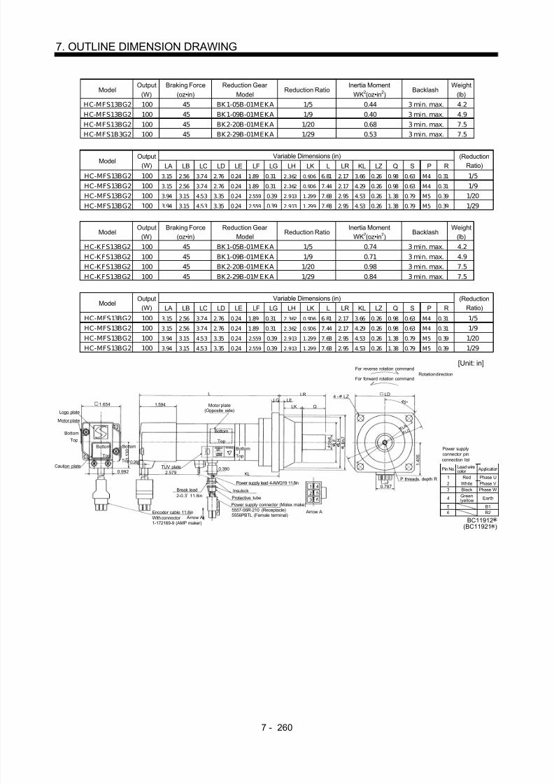
8/10/2019 Servo Motor - Instruction Manual SH(NA)-3181-D (03.00)
http://slidepdf.com/reader/full/servo-motor-instruction-manual-shna-3181-d-0300 339/368

8/10/2019 Servo Motor - Instruction Manual SH(NA)-3181-D (03.00)
http://slidepdf.com/reader/full/servo-motor-instruction-manual-shna-3181-d-0300 340/368
7 - 261
7. OUTLINE DIMENSION DRAWING
ModelOutput
(W)Braking Force
(oz•in)Reduction Gear
ModelReduction Ratio
Inertia MomentWK2(oz•in 2)
Weight(lb)
HC-MFS23BG2 200 184 BK1-05B-02MEKA 1/5 1.31 6.0HC-MFS23BG2 200 184 BK2-09B-02MEKA 1/9 1.40 9.0HC-MFS23BG2 200 184 BK3-20B-02MEKA 1/20 2.21 12.3
HC-MFS23BG2 200 184 BK3-29B-02MEKA 1/29 1.77 12.3
Variable Dimensions (in)Model
Output(W) LA LB LC LD LE LF LG LH LK L LR KL LZ Q S P R
(ReductionRatio)
HC-MFS23BG2 200 3.15 2.56 3.74 2.76 0.24 1.89 0.31 2.362 0.906 7.44 2.17 4.20 0.26 0.98 0.63 M4 0.31 1/5HC-MFS23BG2 200 3.94 3.15 4.53 3.35 0.24 2.559 0.39 2.913 1.299 8.15 2.95 4.91 0.26 1.38 0.79 M5 0.39 1/9HC-MFS23BG2 200 4.53 3.74 5.31 3.94 0.31 2.953 0.39 3.346 1.378 8.35 3.35 5.10 0.35 1.57 0.98 M6 0.47 1/20HC-MFS23BG2 200 4.53 3.74 5.31 3.94 0.31 2.953 0.39 3.346 1.378 8.35 3.35 5.10 0.35 1.57 0.98 M6 0.47 1/29
ModelOutput
(W)Braking Force
(oz•in)Reduction Gear
ModelReduction Ratio
Inertia MomentWK2(oz•in 2)
Weight(lb)
HC-KFS23BG2 200 184 BK1-05B-02MEKA 1/5 3.12 6.0HC-KFS23BG2 200 184 BK2-09B-02MEKA 1/9 3.23 9.0HC-KFS23BG2 200 184 BK3-20B-02MEKA 1/20 4.05 12.3
HC-KFS23BG2 200 184 BK3-29B-02MEKA 1/29 3.61 12.3
Variable Dimensions (in)Model
Output(W) LA LB LC LD LE LF LG LH LK L LR KL LZ Q S P R
(ReductionRatio)
HC-KFS23BG2 200 3.15 2.56 3.74 2.76 0.24 1.89 0.31 2.362 0.906 7.44 2.17 4.20 0.26 0.98 0.63 M4 0.31 1/5HC-KFS23BG2 200 3.94 3.15 4.53 3.35 0.24 2.559 0.39 2.913 1.299 8.15 2.95 4.91 0.26 1.38 0.79 M5 0.39 1/9HC-KFS23BG2 200 4.53 3.74 5.31 3.94 0.31 2.953 0.39 3.346 1.378 8.35 3.35 5.10 0.35 1.57 0.98 M6 0.47 1/20HC-KFS23BG2 200 4.53 3.74 5.31 3.94 0.31 2.953 0.39 3.346 1.378 8.35 3.35 5.10 0.35 1.57 0.98 M6 0.47 1/29
[Unit:in]
BC11913
Logo plate
Motor plate
Encoder cable11.8in
Motor plate(Opposite side)
LGLR
L
LELK Q
2.667 0.390KL
Top
Bottom
Top
TUV plate
Caution plate
For reverse rotation command
For forward rotation commandRotation direction
LD
P threads, depth R
S h 6
L F L B h 7
0.7871 4
2 5
4 - LZ
TopBottom
L C
4 5 °
5557-06R-210 (Receptacle)5556PBTL (Female terminal)
Power supply connector (Molex make)Protective tube
Power supply lead 4-AWG19 11.8in
L H
Arrow A
Insulock
3 6
Arrow A
(BC11922 )
Break lead2-0.3 11.8in2
With conne ctor1-172169-9(AMP maker)
L A
1 . 6 8 5
1.6142.441 0.106
0.417
0.992
1 . 5 1 2
Power supplyconnector pinconnection list
123
4
Pin No.
RedWhiteBlackGreen/yellow
Application
Phase UPhase VPhase W
Earth
Lead wirecolor
56
B1B2
Bottom
BottomTop

8/10/2019 Servo Motor - Instruction Manual SH(NA)-3181-D (03.00)
http://slidepdf.com/reader/full/servo-motor-instruction-manual-shna-3181-d-0300 341/368
7 - 262
7. OUTLINE DIMENSION DRAWING
ModelOutput
(W)Braking Force
(oz•in)Reduction Gear
ModelReduction Ratio
Inertia MomentWK2(oz•in 2)
Weight(lb)
HC-MFS43BG2 400 184 BK2-05B-04MEKA 1/5 1.88 9.5HC-MFS43BG2 400 184 BK3-09B-04MEKA 1/9 2.03 13.0HC-MFS43BG2 400 184 BK4-20B-04MEKA 1/20 2.59 17.9
HC-MFS43BG2 400 184 BK4-29B-04MEKA 1/29 2.11 17.9
Variable Dimensions (in)Model
Output(W) LA LB LC LD LE LF LG LH LK L LR KL LZ Q S P R
(ReductionRatio)
HC-MFS43BG2 400 3.94 3.15 4.53 3.35 0.24 2.559 0.39 2.913 1.299 8.50 2.95 5.18 0.26 1.38 0.79 M5 0.39 1/5HC-MFS43BG2 400 4.53 3.74 5.31 3.94 0.31 2.953 0.39 3.346 1.378 9.33 3.35 6.01 0.35 1.57 0.98 M6 0.47 1/9HC-MFS43BG2 400 5.31 4.33 6.10 4.53 0.31 3.543 0.47 3.937 1.575 9.57 3.94 6.24 0.43 1.97 1.26 M8 0.63 1/20HC-MFS43BG2 400 5.31 4.33 6.10 4.53 0.31 3.543 0.47 3.937 1.575 9.57 3.94 6.24 0.43 1.97 1.26 M8 0.63 1/29
ModelOutput
(W)Braking Force
(oz•in)Reduction Gear
ModelReduction Ratio
Inertia MomentWK2(oz•in 2)
Weight(lb)
HC-KFS43BG2 400 184 BK2-05B-04MEKA 1/5 4.76 9.5HC-KFS43BG2 400 184 BK3-09B-04MEKA 1/9 4.92 13.0HC-KFS43BG2 400 184 BK4-20B-04MEKA 1/20 5.47 17.9
HC-KFS43BG2 400 184 BK4-29B-04MEKA 1/29 5.03 17.9
Variable Dimensions (in)Model
Output(W) LA LB LC LD LE LF LG LH LK L LR KL LZ Q S P R
(ReductionRatio)
HC-KFS43BG2 400 3.94 3.15 4.53 3.35 0.24 2.559 0.39 2.913 1.299 8.50 2.95 5.18 0.26 1.38 0.79 M5 0.39 1/5HC-KFS43BG2 400 4.53 3.74 5.31 3.94 0.31 2.953 0.39 3.346 1.378 9.33 3.35 6.01 0.35 1.57 0.98 M6 0.47 1/9HC-KFS43BG2 400 5.31 4.33 6.10 4.53 0.31 3.543 0.47 3.937 1.575 9.57 3.94 6.24 0.43 1.97 1.26 M8 0.63 1/20HC-KFS43BG2 400 5.31 4.33 6.10 4.53 0.31 3.543 0.47 3.937 1.575 9.57 3.94 6.24 0.43 1.97 1.26 M8 0.63 1/29
Power supplyconnector pinconnection list
123
4
Pin No.
RedWhiteBlackGreen/yellow
Application
Phase UPhase VPhase W
Earth
Lead wirecolor
BC11914(BC11923)
56
B1B2
[Unit: in]
Logo plate
Motor plate
With connector 1-172169-9(AMP maker)
Encoder cable 11.8in
Motor plate(Opposite side)
LGLRL
LE
LK Q
2.6770.390
KL
Bottom
Top
TUV plate
Caution plate
For reverse rotation command
For forward rotation commandRotation direction
LD
L A
P threads, depthR
S h 6
L F L B h 7
0.7871 42 5
Arrow A
4 - LZ
Top
Bottom L C
1 . 6 8 5
4 5 °
5557-06R-210 (Receptacle)5556PBTL (Female terminal)
Power supply connector (Molex make)
Protective tube
Power supply lead 4-AWG19 11.8in
L H
Arrow A
Break cableVCTF 2-0.3 11. 8in2
Insulock
3 6
1.6142.441
0.106
0.4170.992
1 . 5 1 2Top
Bottom
TopBottom

8/10/2019 Servo Motor - Instruction Manual SH(NA)-3181-D (03.00)
http://slidepdf.com/reader/full/servo-motor-instruction-manual-shna-3181-d-0300 342/368
7 - 263
7. OUTLINE DIMENSION DRAWING
ModelOutput
(W)Braking Force
(oz•in)Reduction Gear
ModelReduction Ratio
Inertia MomentWK2(oz•in 2)
Weight(lb)
HC-MFS73BG2 750 340 BK3-05B-08MEKA 1/5 6.00 16.1HC-MFS73BG2 750 340 BK4-09B-08MEKA 1/9 6.04 21.2HC-MFS73BG2 750 340 BK5-20B-08MEKA 1/20 6.24 28.7
HC-MFS73BG2 750 340 BK5-29B-08MEKA 1/29 5.66 28.7
Variable Dimensions (in)Model
Output(W) LA LB LC LD LE LF LG LH LK L LR KL LZ Q S P R
(ReductionRatio)
HC-MFS73BG2 750 4.53 3.74 5.31 3.94 0.31 2.953 0.39 3.346 1.378 9.74 3.35 6.17 0.35 1.57 0.98 M6 0.47 1/5HC- MFS73BG2 750 5.31 4.33 6.10 4.53 0.31 3.543 0.47 3.937 1.575 11.16 3.94 7.59 0.43 1.97 1.26 M8 0.63 1/9HC- MFS73BG2 750 5.91 4.92 6.89 5.12 0.39 4.134 0.59 4.528 1.693 11.16 4.53 7.59 0.55 2.36 1.57 M10 0.79 1/20HC- MFS73BG2 750 5.91 4.92 6.89 5.12 0.39 4.134 0.59 4.528 1.693 11.16 4.53 7.59 0.55 2.36 1.57 M10 0.79 1/29
Power supplyconnector pinconnection list
123
4
Pin No.
RedWhiteBlackGreen/yellow
Application
Phase UPhase VPhase W
Earth
Lead wirecolor
BC11915
56
B1B2
[Unit: in]
Logo plate
Motor plate
With connector 1-172169-9(AMP maker)
Encoder cable 11.8in
Motor plate
(Opposite side)
LG
LRL
LE
LK Q
0.390 KL
Bottom
Top
TUV plate
Caution plate
For reverse rotation command
For forward rotation commandRotation direction
LD
L A
P threads, depthR
S h 6
L F L B h 7
0.7871 42 5
Arrow A
4 - LZ
TopBottom
L C
2 . 2 8 7
4 5 °
5557-06R-210 (Receptacle)5556PBTL (Female terminal)
Power supply connector (Molex make)Protective tube
Power supply lead 4-AWG19 11.8in
L H
Arrow A
Break cableVCTF 2-0.3 1 1.8in2
Insulock
3 6
1.5353.228
0.106
0.992
1 . 9 1 7
0.4332.835
BottomTop
TopBottom

8/10/2019 Servo Motor - Instruction Manual SH(NA)-3181-D (03.00)
http://slidepdf.com/reader/full/servo-motor-instruction-manual-shna-3181-d-0300 343/368
7 - 264
7. OUTLINE DIMENSION DRAWING
7.2.11 HC-UFS 3000r/min Series
(1) Standard (without electromagnetic brake)
ModelOutput
(W)Inertia Moment
WK2(oz•in 2)Weight
(lb)
HC-UFS13 100 0.36 1.76
Power supplyconnector pinconnection list
123
4
Pin No.
RedWhiteBlackGreen/yellow
Application
Phase UPhase VPhase W
Earth
Lead wirecolor
[Unit: in]
BC11876
0.787
5557-04R-210 (Receptacle)5556PBTL (Female terminal)
With connector 1-172169-9(AMP maker)
Arrow A
4 5 °
1 . 6 8 5
Bottom
Top
Protective tube
Motor plate(Opposite side)
1 . 9 6 9
2.362
0 . 3 1 5
Logo plate
Power supply connector (Molex make)Encoder cable 11.8in
Motor plate
Caution plate
Bottom
TopBottom
Top
0.984
0.118
0.197
2.756
0.3901.299
1.059
1 . 5 7 5
4- 0.228
Power supply lead 4-AWG19 11.8in
TUV plate
Arrow A
Top
Bottom
1
2 4
3
0.236
1 . 5 7 5
Oil sealSC10207
R 5
2 .7 5 6
Variable Dimensions (in)Model
Output(W) L KL
Inertia MomentWK2(oz•in 2)
Weight(lb)
HC-UFS23 200 3.03 1.72 1.32 3.31HC-UFS43 400 3.62 2.31 2.00 3.75
Power supplyconnector pinconnection list
123
4
Pin No.
RedWhiteBlackGreen/yellow
Application
Phase UPhase VPhase W
Earth
Lead wirecolor
[Unit:in]
BC11877
0.787
5557-04R-210 (Receptacle)5556PBTL (Female terminal)
With connector 1-172169-9(AMP maker)
Arrow A
4 5 °
2 . 1 6 5
Bottom
Top
Protective tube
Motor plate(Opposite side)
2 . 7 5 6
3.150
0 . 5 5 1
Logo plate
Power supply connector (Molex make)Encoder cable 11.8in
Motor plate
Caution plate
Bottom
Top
Bottom
Top
KL
1.181
0.1180.315
L
0.3901.059
1 . 9 6 9
4- 0.260
Power supply lead 4-AWG19 11.8in
TUV plate
Arrow A
Top
Bottom
1
2 4
3
0.256
2 . 2 0 5
Oil sealSC15307
R 7
3 .5 4 3

8/10/2019 Servo Motor - Instruction Manual SH(NA)-3181-D (03.00)
http://slidepdf.com/reader/full/servo-motor-instruction-manual-shna-3181-d-0300 344/368

8/10/2019 Servo Motor - Instruction Manual SH(NA)-3181-D (03.00)
http://slidepdf.com/reader/full/servo-motor-instruction-manual-shna-3181-d-0300 345/368
7 - 266
7. OUTLINE DIMENSION DRAWING
Variable Dimensions (in)Model
Output(W) L KL
Braking Force(oz•in)
Inertia MomentWK2(oz•in 2)
Weight(lb)
HC-UFS23B 200 4.37 1.72 184.1 1.77 4.85HC-UFS43B 400 4.96 2.31 184.1 2.44 5.29
Power supplyconnector pinconnection list
123
4
Pin No.
RedWhiteBlackGreen/yellow
Application
Phase UPhase VPhase W
Earth
Lead wirecolor
[Unit: in]
BC11885
0.787
5557-06R-210 (Receptacle)5556PBTL (Female terminal)
With connector 1-172169-9 (AMP maker)
Arrow A
4 5 °
2 . 1 6 5
Bottom
Top
Protective tube
Motor plate(Opposite side)
Logo plate
Power supply connector (Molex make)
Encoder cable 11.8in
Motor plate
Caution plate
Bottom
Top
Bottom
Top
L
0.3901.059
1 . 9 6 9
Power supply lead 4-AWG19 11.8in
TUV plate
Arrow A
Top
12 5
4
Oil sealSC15307KL
Bottom
Insulock
Break cable
VCTF 2-0.3 11.8in23 6
R 7
56
B1B2
1.181
0.118
0.315 0.256
2 . 7 5 6
0 . 5 5 1
2 . 2 0 5
1.858
3.150
4- 0.260
3 .5 4 3
ModelOutput
(W)Braking Force
(oz•in)Inertia Moment
WK2(oz•in 2)Weight
(lb)HC-UFS73B 750 339.87 33.35 13.67
Power supplyconnector pinconnection list
123
4
Pin No.
RedWhiteBlackGreen/yellow
Application
Phase UPhase VPhase W
Earth
Lead wirecolor
[Unit: in]
BC11886
5557-06R-210 (Receptacle)5556PBTL (Female terminal)
With connector 1-172169-9 (AMP maker)
Arrow A
4 5 °
Bottom
Top
Protective tube
Motor plate(Opposite side)
Logo plate
Power supply connector (Molex make)
Encoder cable 11.8in
Motor plate
Caution plate
BottomTop
Bottom
Top
2.992
Power supply lead 4-AWG19 11.8in
TUV plate
Arrow A
Top
1
2 5
4
Oil sealSC20357
Bottom
Insulock
Break cable
VCTF 2-0.3 11.8in2
3 6 56
B1B2
3.780
2.185
1.059
2 . 8 3 5
1.575
0.138
0.394 0.236
1.280
4.370
4 . 3 3 1 0 . 7
4 8
3 . 1 5 0
0.787
2 . 9 9 2
4.843
4- 0.354
5 . 7 0
9
6. 4 9 6

8/10/2019 Servo Motor - Instruction Manual SH(NA)-3181-D (03.00)
http://slidepdf.com/reader/full/servo-motor-instruction-manual-shna-3181-d-0300 346/368
7 - 267
7. OUTLINE DIMENSION DRAWING
7.3 Connector
(1) Coupler type<Nippon AMP make>
POINT
ModelHousing
Connector pin
Crimping tool
: 1-172161-9
: 170359-1
: 755330-1
14 (0.55) 23.7 (0.93)
16(0.63)
4.2 (0.17)
14(0.55)
4.2(0.17)
[Unit: mm]([Unit: in])
The crimping tool is required for wiring tothe connector.
For the crimping tool, contact Nippon AMP.
(2) Cannon connector type(a) Connectors
<Daiichi Denshi Kogyo make>
[Unit: mm]
([Unit: in])
CE05-6A14S-2SD-B
3-20UNEF-2A threads
D terminal
5.6 (0.22) 24 (0.94)
28.57
( 1.12)
CL1
CL2
-20UNEF-2B threads
JAPAN
DDK
A
B C
D
CE05
1 4S-2
487
[Unit: mm]([Unit: in])
Model A B C D W
CE05-6A22-23SD-B-BSS 1 3/8-18UNEF-2B 40.48
(1.59)
38.3
(1.51)
61
(2.40)
1 3/16-18UNEF-2A
CE05-6A24-10SD-B-BSS 1 1/2-18UNEF-2B 43.63
(1.72)42.0
(1.65)68
(2.68) 1 7/16-18UNEF-2A
W A
7.85 (0.31) or more
D or less
C B
OE05-6A32-17SD-B-BSS 2-18UNS-2S 56.33
(2.22)54.2
(2.13)79
(3.11) 1 3/4-18UNS-2A

8/10/2019 Servo Motor - Instruction Manual SH(NA)-3181-D (03.00)
http://slidepdf.com/reader/full/servo-motor-instruction-manual-shna-3181-d-0300 347/368
7 - 268
7. OUTLINE DIMENSION DRAWING
AD or less
R
U
Yor more
S
W
B
[Unit: mm]([Unit: in])
Model A B D W R U S Y
CE05-8A22-23SD-B-BAS 1 3/8-18UNEF-2B 40.48
(1.59)75.5
(2.97) 1 3/16-18UNEF-2A
16.3(0.64)
33.3(1.31)
49.6(1.95)
7.5(0.30)
CE05-8A24-10SD-B-BAS 1 1/2-18UNEF-2B 43.63(1.72)
86.3(3.40)
1 7/16-18UNEF-2A 18.2(0.72)
36.5(1.44)
54.7(2.15)
7.5(0.30)
CE05-8A32-17SD-B-BAS 2-18UNS-2B 56.33
(2.22)93.5
(3.68) 1 3/4-18UNS-2A
24.6(0.97)
44.5(1.75)
61.9(2.44)
8.5(0.34)
Gasket
H or lessD
CE
AJ
G B
[Unit: mm]([Unit: in])
Model A B C D E G J
MS3106A10SL-4S(D190) 5/8-24UNEF-2B 22.22
(0.87)23.3
(0.92)9/16-24UNEF-2A
7.5(0.30)
12.5(0.49)
13.49(0.53)
MS3106A14S-2S(D190) 7/8-20UNEF-2B 28.57
(1.13)24.34(0.96)
3/4-20UNEF-2A 8.46
(0.33)17.0
(0.67)13.49(0.53)
MS3106A20-29S(D190) 1 1/4-18UNEF-2B 37.28
(1.47)34.11(1.34)
1 1/8-18UNEF-2A 12.16
(0.48)26.8
(1.06)18.26(0.72)
MS3106A22-23S(D190) 1 3/8-18UNEF-2B 40.48
(1.59)34.11(1.34)
1 1/4-18UNEF-2A 12.15
(0.48)29.9
(1.18)18.26(0.72)
MS3106A24-10S(D190) 1 1/2-18UNEF-2B 43.63
(1.72)36.58(1.44)
1 3/8-18UNEF-2A 13.42
(0.53)32.9
(1.30)18.26(0.72)
MS3106A32-17S(D190) 2-18UNS-2B 56.33
(2.22)36.95(1.46)
1 7/8-16UN-2A 13.14
(0.52)45.3
(1.78)18.26(0.72)
Contact Size
# 16 # 12 # 8 # 4 # 0
H 8 or less 8 or less 10 or less 13 or less 13 or less

8/10/2019 Servo Motor - Instruction Manual SH(NA)-3181-D (03.00)
http://slidepdf.com/reader/full/servo-motor-instruction-manual-shna-3181-d-0300 348/368
7 - 269
7. OUTLINE DIMENSION DRAWING
[Unit: mm]([Unit: in])
Model A J L Q V W Y
MS3106B14S-2S 7/8-20UNEF 13.49
(0.53)42.88(1.69)
28.57(1.13)
3/4-20UNEF 8.0
(0.32)30
(1.18)
MS3106B20-29S 1 1/4-18UNEF 18.26(0.72)
55.57(2.19)
37.28(1.47)
1 3/16-18UNEF 9.53(0.38)
47(1.85)
MS3106B22-23S 1 3/8-18UNEF 18.26
(0.72)55.57(2.19)
40.48(1.59)
1 3/16-18UNEF 9.53
(0.38)50
(1.97)
MS3106B24-10S 1 1/2-8UNEF 18.26
(0.72)58.72(2.31)
43.63(1.72)
1 7/16-18UNEF 9.53
(0.38)53
(2.09)
W or moreL or less
J
A
V
Yorless
Q
MS3106B32-17S 2-18UN S 18.26
(0.72)61.92(2.44)
56.33(2.22)
1 3/4-18UNS 11.13
(0.44)66
(2.60)
[Unit: mm]([Unit: in])
Model A J L Q R U V W
MS3106B14S-2S 7/8-20UNEF 13.49
(0.53)53.97(2.13)
28.57(1.13)
14.9(0.59)
27.0(1.06) 3/4-20UNEF
9.53(0.38)
MS3106B20-29S 1 1/4-18UNEF 18.26
(0.72)76.98(3.03)
37.28(1.47)
22.5(0.89)
33.3(1.31)
1 3/16-18UNEF 9.53(0.38)
MS3106B22-23S 1 3/8-18UNEF 18.26
(0.72)76.98(3.03)
40.48(1.59)
24.1(0.95)
33.3(1.31)
1 3/16-18UNEF 9.53(0.38)
MS3106B24-10S 1 1/2-8UNEF 18.26
(0.72)86.51(3.41)
43.63(1.72)
25.6(1.01)
36.5(1.44)
1 7/16-18UNEF 9.53(0.38)
W ormore
L or less J
Q A
V
U
R
MS3106B32-17S 2-18UN S 18.26
(0.72)95.25(3.75)
56.33(2.22)
32.8(1.29)
44.4(1.75)
1 3/4-18UNS 11.13
(0.44)
(b) Flexible conduit connectors<Daiwa Dengyo make>
D ( D 1 )
L A0
C C
L1
D2
L 2
A0
MSA MAA
[Unit: mm]([Unit: in])
Model A 0 C L L1 L2 D D1 D2
MSA-10-10 • MAA-10-10 9/16-24UNEF-2B 8.2(0.32)
44(1.73)
35.5(1.40)
45(1.77)
27(1.06)
29(1.14)
26(1.02)
MSA-10-14 • MAA-10-14 3 /4-20UNEF-2B 8.2(0.32)
45(1.77)
39.5(1.56)
46(1.18)
27(1.06)
29(1.14)
35(1.38)
MSA-12-14 • MAA-12-14 3 /4-20UNEF-2B 10.7(0.42) 45(1.77) 39.5(1.56) 46(1.18) 27(1.06) 29(1.14) 35(1.38)
MSA-16-20 • MAA-16-20 1 1/8-18UNEF-2B 14
(0.55)49.5
(1.95)47
(1.85)52
(2.05)36
(1.42)38
(1.50)39
(1.54)
MSA-16-22 • MAA-16-22 1 1/4-18UNEF-2B 14
(0.55)49.5
(1.95)47
(1.85)52
(2.05)38
(1.50)42
(1.65)39
(1.54)
MSA-16-24 • MAA-16-24 1 3/8-18UNEF-2B 14
(0.55)49.5
(1.95)51
(2.01)54
(2.13)41
(1.61)43
(1.69)47
(1.85)
MSA-22-20 • MAA-22-20 1 1/8-18UNEF-2B 18.9
(0.74)49.5
(1.95)47
(1.85)54
(2.13)36
(1.42)39
(1.54)39
(1.54)
MSA-22-22 • MAA-22-22 1 1/4-18UNEF-2B 18.9
(0.74)49.5
(1.95)47
(1.85)54
(2.13)38
(1.50)42
(1.65)39
(1.54)
MSA-22-24 • MAA-22-24 1 3/8-18UNEF-2B 18.9(0.74)
49.5(1.95)
51(2.01)
56(2.21)
41(1.61)
43(1.69)
47(1.85)
MSA-28-22 • MAA-28-22 1 1/4-18UNEF-2B 24.5(0.97)
51(2.01)
53(2.09)
64(2.52)
46(1.18)
50(1.97)
47(1.85)
MSA-28-24 • MAA-28-24 1 3/8-18UNEF-2B 24.5(0.97) 51(2.01) 53(2.09) 66(2.60) 46(1.18) 50(1.97) 47(1.85)

8/10/2019 Servo Motor - Instruction Manual SH(NA)-3181-D (03.00)
http://slidepdf.com/reader/full/servo-motor-instruction-manual-shna-3181-d-0300 349/368
7 - 270
7. OUTLINE DIMENSION DRAWING
A A1
E' F' G'
Threads C
dd1
E
G
F
L(1)L1(2)
[Unit: mm]([Unit: in])
Jam Nut Lock Nut
Model Threads C A A 1 d d 1
EWidth
AcrossFlats
FWidth
AcrossCorners
GNumber
Of Corners
E'Width
AcrossFlats
F'Width
AcrossCorners
G'Number
Of Corners
L L1
RCC-102RL-MS10F 9/16-24UNEF-2B 6
(0.24)
15
(0.59)
8.3
(0.33)
11.0
(0.43)
24
(0.95)
26.4
(1.04) 6
24
(0.95)
26.4
(1.04) 6
39
(1.54)
36
(1.42)
RCC-102RL-MS14F 3/4-20UNEF-2B 7
(0.28)15
(0.59)8.3
(0.33)15.0
(0.59)24
(0.95)26.4
(1.04) 6
24(0.95)
26.4(1.04)
6 40
(1.58)37
(1.46)
RCC-103RL-MS14F 3/4-20UNEF-2B 7
(0.28)15
(0.59)10.6
(0.42)15.0
(0.59)27
(1.06)29.7
(1.17) 6
26(1.02)
28.6(1.13)
6 44
(1.73)41
(1.61)
RCC-104RL-MS14F 3/4-20UNEF-2B 7
(0.28)15
(0.59)14.0
(0.55)15.0
(0.59)30
(1.18)33.0
(1.30) 6
30(1.18)
33.0(1.30)
6 45
(1.77)42
(1.65)
RCC-104RL-MS20F 1• 1/8-18UNEF-2B 9(0.35)
15(0.59)
14.0(0.55)
24.0(0.95)
30(1.18)
33.0(1.30)
6 32
(1.26)35.2
(1.39) 6
47(1.85)
44(1.73)
RCC-104RL-MS22F 1• 1/4-18UNEF-2B 9(0.35)
15(0.59)
14.0(0.55)
27.0(1.06)
30(1.18)
33.0(1.30)
6 36
(1.42)39.6
(1.56) 6
47(1.85)
44(1.73)
RCC-104RL-MS24F 1• 3/8-18UNEF-2B 10
(0.39)20
(0.79)14.0
(0.55)30.0
(1.18)30
(1.18)33.0
(1.30) 6
40(1.58)
42.5(1.67)
8 54
(2.13)50
(1.97)
RCC-106RL-MS20F 1• 1/8-18UNEF-2B 9
(0.35)
15
(0.59)
19.0
(0.75)
24.0
(0.95)
37
(1.46)
40.7
(1.60)
6 36
(1.42)
39.6
(1.56)
6 50
(1.97)
46
(1.81)RCC-106RL-MS22F 1• 1/4-18UNEF-2B
9(0.35)
15(0.59)
19.0(0.75)
27.0(1.06)
37(1.46)
40.7(1.60)
6 36
(1.42)39.6
(1.56) 6
50(1.97)
46(1.81)
RCC-106RL-MS24F 1• 3/8-18UNEF-2B 10
(0.39)20
(0.79)19.0
(0.75)30.0
(1.18)37
(1.46)40.7
(1.60) 6
40(1.58)
42.5(1.67)
8 56
(2.21)52
(2.05)
RCC-106RL-MS32F 1• 7/8-16UN-2B 11
(0.43)20
(0.79)19.0
(0.75)42.5
(1.67)37
(1.46)40.7
(1.60) 6
52(2.05)
54.5(2.15)
8 57
(2.24)53
(2.09)
RCC-108RL-MS22F 1• 1/4-18UNEF-2B 9(0.35)
15(0.59)
24.4(0.96)
27.0(1.06)
45(1.77)
47.3(1.86)
8 44
(1.73)46.3
(1.82) 8
55(2.17)
50(1.97)
RCC-108RL-MS24F 1• 3/8-18UNEF-2B 10
(0.39)20
(0.79)24.4
(0.96)30.0
(1.18)45
(1.77)47.3
(1.86) 8
44(1.73)
46.3(1.82)
8 60
(2.36)55
(2.17)
RCC-108RL-MS32F 1• 7/8-16UN-2B 11
(0.43)20
(0.79)24.4
(0.96)42.5
(1.67)45
(1.77)47.3
(1.86) 8
52(2.05)
54.5(2.15)
8 61
(2.40)56
(2.21)

8/10/2019 Servo Motor - Instruction Manual SH(NA)-3181-D (03.00)
http://slidepdf.com/reader/full/servo-motor-instruction-manual-shna-3181-d-0300 350/368
7 - 271
7. OUTLINE DIMENSION DRAWING
L1(1)
L2(2)
A A1
E F G
Threads C
d
d1
E' G'
F'
L
9 0 °
[Unit: mm]([Unit: in])
Jam Nut Lock Nut
Model Threads C A A 1 d d 1
EWidth
Across
Flats
FWidth
Across
Corners
GNumber
Of
Corners
E'Width
Across
Flats
F'Width
Across
Corners
G'Number
Of
Corners
L L1 L2
RCC-302RL-MS10F 9/16-24UNEF-2B 6
(0.24)15
(0.59)8.3
(0.33)10.0
(0.39)24
(0.95)26.4
(1.04) 6
20(0.79)
22.0(0.87)
6 35
(1.38)33
(1.30)30
(1.18)
RCC-302RL-MS14F 3/4-20UNEF-2B 7
(0.28)15
(0.59)8.3
(0.33)13.8
(0.54)24
(0.95)26.4
(1.04) 6
23(0.91)
25.3(1.0)
6 35
(1.38)33
(1.30)30
(1.18)
RCC-303RL-MS14F 3/4-20UNEF-2B 7
(0.28)15
(0.59)10.6
(0.42)13.8
(0.54)27
(1.06)29.7
(1.17) 6
23(0.91)
25.3(1.0)
6 37
(1.46)37
(1.46)34
(1.34)
RCC-304RL-MS14F 3/4-20UNEF-2B 7
(0.28)15
(0.59)14.0
(0.55)13.8
(0.54)30
(1.18)33.0
(1.30) 6
23(0.91)
25.3(1.0)
6 39
(1.54)38
(1.50)35
(1.38)
RCC-304RL-MS20F 1• 1/8-18UNEF-2B 9
(0.35)15
(0.59)14.0
(0.55)23.2
(0.91)30
(1.18)33.0
(1.30) 6
32(1.26)
35.2(1.39)
6 41
(1.61)38
(1.50)35
(1.38)
RCC-304RL-MS22F 1• 1/4-18UNEF-2B 9
(0.35)15
(0.59)14.0
(0.55)26.5
(1.04)30
(1.18)33.0
(1.30) 6
36(1.42)
39.6(1.56)
6 41
(1.61)38
(1.50)35
(1.38)
RCC-304RL-MS24F 1• 3/8-18UNEF-2B 10
(0.39)
20
(0.79)
14.0
(0.55)
28.7
(1.13)
30
(1.18)
33.0
(1.30) 6
40
(1.58)
42.5
(1.67) 8
47
(1.85)
46
(1.81)
43
(1.69)
RCC-306RL-MS20F 1• 1/8-18UNEF-2B 9
(0.35)15
(0.59)19.0
(0.75)23.2
(0.91)37
(1.46)40.7
(1.60) 6
32(1.26)
35.2(1.39)
6 45
(1.77)44
(1.73)40
(1.58)
RCC-306RL-MS22F 1• 1/4-18UNEF-2B 9
(0.35)15
(0.59)19.0
(0.75)26.5
(1.04)37
(1.46)40.7
(1.60) 6
36(1.42)
39.6(1.56)
6 45
(1.77)44
(1.73)40
(1.58)
RCC-306RL-MS24F 1• 3/8-18UNEF-2B 10
(0.39)20
(0.79)19.0
(0.75)28.7
(1.13)37
(1.46)40.7
(1.60) 6
40(1.58)
42.5(1.67)
8 51
(2.01)49
(1.93)45
(1.77)
RCC-306RL-MS32F 1• 7/8-16UN-2B 11
(0.43)20
(0.79)19.0
(0.75)40.6
(1.60)37
(1.46)40.7
(1.60) 6
54(2.13)
56.7(2.23)
8 52
(2.05)49
(1.93)45
(1.77)
RCC-308RL-MS22F 1• 1/4-18UNEF-2B 9
(0.35)15
(0.59)24.4
(0.96)26.5
(1.04)45
(1.77)47.3
(1.86) 8
36(1.42)
39.6(1.56)
6 49
(1.93)50
(1.97)45
(1.77)
RCC-308RL-MS24F 1• 3/8-18UNEF-2B 10
(0.39)20
(0.79)24.4
(0.96)28.7
(1.13)45
(1.77)47.3
(1.86) 8
40(1.58)
42.5(1.67)
8 56
(2.21)50
(1.97)45
(1.77)
RCC-308RL-MS32F 1• 7/8-16UN-2B 11
(0.43)20
(0.79)24.4
(0.96)40.6
(1.60)45
(1.77)47.3
(1.86) 8
54(2.13)
56.7(2.23)
8 62
(2.44)50
(1.97)45
(1.77)
(c) Back shell<Daiichi Denshi Kogyo make>
± 35 (1.38)
O ring
35( 1.38)
33.3 (1.31)
48.3 (1.90) 15 (0
.59)
17.8
( 0.70)
10.9
11/8 -18UNEF-2B11/8 -18UNEF-2B
13/16 -18UNEF-2A
13/16 -18UNEF-2A
7.85 (0.31)or more
Effective thread length
CL
CL
31.6 (1.24)(Spanner fitting)
CE-20BA-S50.5 (1.99) or less
O ring 36
( 1.42)
39.6 (1.56) or le ss
7.5 (0.30) or more
CE02-20BS-S

8/10/2019 Servo Motor - Instruction Manual SH(NA)-3181-D (03.00)
http://slidepdf.com/reader/full/servo-motor-instruction-manual-shna-3181-d-0300 351/368
7 - 272
7. OUTLINE DIMENSION DRAWING
(d) Cable clamps<Daiichi Denshi Kogyo make>
A
1.6 (0.06)
VB
G
E (Bushing ID)
D (Cable clamp ID)
F (Movable range)
Effective threadlength
10.3 (0.41)
[Unit: mm]([Unit: in])
Model Shell Size A B C D E F G V Bushing
MS3057-6A 14S 22.2(0.87)
24.6(0.97)
10.3(0.41)
11.2(0.44)
7.9(0.31)
2.0(0.08)
27.0(1.06) 3/4-20UNEF AN3420-6
MS3057-12A 20,22 23.8(0.94)
35.0(1.38)
10.3(0.41)
19.0(0.75)
15.9(0.63)
4.0(0.16)
37.3(1.47) 1 3/16-18UNEF AN3420-12
MS3057-16A 24,28 26.2(1.03)
42.1(1.66)
10.3(0.41)
23.8(0.94)
15.9(0.63)19.1
(0.75)
4.8(0.19)
42.9(1.69) 1 7/1618UNEF AN3420-12
AN3420-16
MS3057-20A 32 27.8(1.09)
51.6(2.03)
11.9(0.47)
31.7(1.25)
19.1(0.75)23.8
(0.94)
6.3(0.25)
51.6(2.03) 1 3/4-18UNS AN3420-16
AN3420-20
(BushingID)
Effective thread lengthC
A
1.6 (0.06)V threads
B
G
F E
(Cable clamp ID)H
(One-side movable range)
D
[Unit: mm]([Unit: in])
Model Shell Size A B C D E F G H V Bushing Cable Range
CE 3057-12A-1 16(0.63) CE3420-12-1 12.5 to 16
CE 3057-12A-2 13(0.51) CE3420-12-2 9.5 to 13
CE 3057-12A-3
2022
23.8(0.94)
35.0(1.38)
10.3(0.41)
41.3(1.63)
19.0(0.75)
10(0.39)
37.3(1.47)
4(0.16) 1 3/16-18UNEF-2B
CE3420-12-3 6.8 to 10
CE 3057-16A-1 19.1(0.75) CE3420-16-1 15 to 19.1
CE 3057-16A-224 26.2
(1.03)42.1
(1.66)10.3
(0.41)41.3
(1.63)23.8
(0.94) 15.5(0.61)
42.9(1.69)
4.8(0.19) 1 7/16-18UNEF-2B
CE3420-16-2 13 to 15.5
CE3057-20A-1 32 27.8(1.09)
51.6(2.03)
11.9(0.47)
43(1.69)
31.7(1.25)
23.8(0.94)
51.6(2.03)
6.3(0.25) 1 3/4-18UN S-2B CE3420-20-1 22 to 23.8
<Daiwa Dengyo make>
O ring
O ring
AO
AO
L
D2
L1
L2D(D1)
[Unit: mm]([Unit: in])
Model Acceptable OD AO L L1 L2 D D1 D2
YSO10-5 to 8•YL O10-5 to 8 5 to 8.3 ( 0.20 to 0.33) 9 /16-24UNE F-2B 43(1.69)
39(1.54)
42.5(1.67)
24(0.94)
26(1.02)
26(1.02)
YSO14-5 to 8•YL O14-5 to 8 5 to 8.3 ( 0.20 to 0.33) YSO14-9 to 11•YL O14-9 to 11 8.3 to 11.3 ( 0.33 to 0.45)
3 /4-20UNEF-2B 44(1.73)
43.5(1.71)
44.5(1.75)
26(1.02)
28(1.10)
35(1.38)

8/10/2019 Servo Motor - Instruction Manual SH(NA)-3181-D (03.00)
http://slidepdf.com/reader/full/servo-motor-instruction-manual-shna-3181-d-0300 352/368
7 - 273
7. OUTLINE DIMENSION DRAWING
<Nippon Flex make>L(1)
L1(2) A 15
(0.59)
Threads C
d
E' F' G'
E
G
F
[Unit: mm]([Unit: in])
Tightening Nut Nipple Body
Model Threads C Applicable
CableDiameter
A dE
Width AcrossFlats
FWidth
AcrossCorners
GNumber
Of Corners
E'Width
AcrossFlats
F'Width
AcrossCorners
G'Number
Of Corners
L L1
ACS-08RL-MS10F
9/16-24UNEF-2B 4.0 to 8.0( 0.16 to 0.32)
6(0.24)
11.0(0.43)
20(0.79)
22.0(0.87)
6 20
(0.79)22.0
(0.87) 6
45(1.77)
40(1.57)
ACS-08RL-MS14F
3/4-20UNEF-2B 4.0 to 8.0( 0.16 to 0.32)
7(0.28)
15.0(0.59)
20(0.79)
22.0(0.87)
6 22
(0.87)24.2
(0.95) 6
46(1.81)
41(1.61)
ACS-12RL-MS10F
9/16-20UNEF-2B 8.0 to 12.0( 0.32 to 0.47)
6(0.24)
11.0(0.43)
24(0.94)
26.4(1.04)
6 24
(0.94)26.4
(1.04) 6
46(1.81)
41(1.61)
ACS-12RL-MS14F
3/4-20UNEF-2B 8.0 to 12.0( 0.32 to 0.47)
7(0.28)
15.0(0.59)
24(0.94)
26.4(1.04)
6 36
(1.42)28.6
(1.13) 6
46(1.81)
41(1.61)
Threads C
d
E F G
L
9 0 °
L1(1) L2(2
)
A15(0.59)
E' G'
F'
[Unit: mm]([Unit: in])
Tightening Nut Nipple Body
Model Threads C Applicable
Cable
Diameter
A dE
Width
AcrossFlats
FWidth
AcrossCorners
GNumber
Of Corners
E'Width
AcrossFlats
F'Width
AcrossCorners
G'Number
Of Corners
L L1 L2
ACA-08RL-MS10F
9/16-24UNEF-2B 4.0 to 8.0( 0.16 to 0.32)
6(0.24)
10.0(0.39)
20(0.79)
22.0(0.87)
6 20
(0.79)22.0
(0.87) 6
35(1.38)
37(1.46)
32(1.26)
ACSA-08RL-MS14F
3/4-20UNEF-2B 4.0 to 8.0( 0.16 to 0.32)
7(0.28)
13.8(0.54)
20(0.79)
22.0(0.87)
6 23
(0.91)25.3
(1.00) 6
36(1.42)
37(1.46)
32(1.26)
ACA-12RL-MS10F
9/16-20UNEF-2B 8.0 to 12.0( 0.32 to 0.47)
6(0.24)
10.0(0.39)
24(0.94)
26.4(1.04)
6 20
(0.79)22.0
(0.87) 6
40(1.57)
43(1.69)
38(1.50)
ACA-12RL-MS14F
3/4-20UNEF-2B 8.0 to 12.0
(0.32 to 0.47)7
(0.28)13.8
(0.54)24
(0.94)26.4
(1.04) 6
23(0.91)
25.3(1.00)
6 41
(1.61)43
(1.69)38
(1.50)

8/10/2019 Servo Motor - Instruction Manual SH(NA)-3181-D (03.00)
http://slidepdf.com/reader/full/servo-motor-instruction-manual-shna-3181-d-0300 353/368
7 - 274
7. OUTLINE DIMENSION DRAWING
MEMO

8/10/2019 Servo Motor - Instruction Manual SH(NA)-3181-D (03.00)
http://slidepdf.com/reader/full/servo-motor-instruction-manual-shna-3181-d-0300 354/368
8 - 1
8. CALCULATION METHODS FOR DESIGNING
8. CALCULATION METHODS FOR DESIGNING
8.1 Specification Symbol List
The following symbols are required for selecting the proper servo: Ta : Acceleration torque [N•m] Td : Deceleration torque [N•m] TMd : Servo motor torque necessary for [N m]
acceleration TMb : Servo motor torque necessary for [N m]
deceleration TLH : Torque applied during servo motor stop [N m] TL : Load torque converted into equivalent [N m]
value on servo motor shaft TLM : Load torque converted into [N m]
equivalent value on servomotor shaft during stop
TU : Unbalance torque [N m] TF : Load friction torque [N m] TLO : Load torque on load shaft [N m] Trms : Continuous effective load torque [N m]
converted into equivalent valueon servo motor shaft
JL : Load inertia moment converted [kg cm 2]into equivalent value on servo
motor shaft JLO : Load inertia moment on load shaft [kg cm 2] JM : Servo motor's rotor inertia moment [kg cm 2]N : Servo motor speed [r/min]No : Servo motor speed during fast feed [r/min]NLO : Load shaft speed during fast feed [r/min]V : Moving part speed [mm/min]Vo : Moving part speed during fast feed [mm/min]PB : Ball screw lead [mm]Z1 : Number of gear teeth on servo motor shaftZ2 : Number of gear teeth on load gear
n : Gear ratio
nZ 1Z 2
Speed reduced when n 1,Speed increased when n 1
: Drive system efficiencyg : Gravitational acceleration (9.8[m/s 2])
: F riction coefficient: Circle ratio (3.14)
P t : Number of feedback pulses in [pulse/rev]position control mode
f : Input pulse frequency in [pps]position control mode
f 0 : Input pulse frequency during fast [pps]feed in position control mode
Tpsa : Acceleration time constant of [s]frequency command inposition control mode
Tpsb : Deceleration time constant of [s]pulse frequency command inposition control mode
K p : Position control gain 1 [rad/s] Tp : Position control time constant (Tp 1/Kp) [s]K v : Speed control gain [rad/s] Tv : Speed control time constant (Tv 1/Kv) [s]
: Feed per feedback pulsein position control mode [mm/pulse]
o : Feed per command pulsein position control mode [mm/pulse]
: Feed [mm]P : Number of internal command pulses [pulse]t s : I nternal settling time [s]to : Positioning time [s]tc : Time at constant speed of servo [s]
motor in 1 cyclet : Stopping time in 1 cycle [s]
: Positioning accuracy [mm]: Number of droop pulses [pulse]
: Load shaft rotation angle per pulse in positioncontrol mode [degree/pulse]
e : Euler constant 2.718278S : Feed per servo motor revolution [mm/rev]

8/10/2019 Servo Motor - Instruction Manual SH(NA)-3181-D (03.00)
http://slidepdf.com/reader/full/servo-motor-instruction-manual-shna-3181-d-0300 355/368
8 - 2
8. CALCULATION METHODS FOR DESIGNING
8.2 Position Resolution and Electronic Gear Setting
Position resolution (travel per pulse ) is determined by travel per servo motor revolution S and thenumber of encoder feedback pulses Pt, and is represented by Equation 8.1:
PtS .............................................................................................................................................................(8.1)
: Travel per pulse [mm] S : Travel per servo motor revolution [mm/rev]
Pt : Number of feedback pulses [pulse/rev]Note: As these values depend on the servo motor series, confirm them in the specifications.
Since has the relationship represented by Equation 8.1, its value is fixed in the control systemafter the drive system and encoder have been determined. However, travel per command pulse canbe set as desired using the parameters.
CMXCDV SM
P t = 8192pulse/rev
Commandpulse train f 0
Electronic gear CMXCDV
Deviationcounter
Encoder
+-
As shown above, command pulses are multiplied by CMX/CDV set in the parameters to be positioncontrol pulses. Travel per command pulse is expressed by Equation 8.2:
o PtS CMX
CDV CMXCDV .......................................................................................................................(8.2)
CMX: Electronic gear (Command pulse multiplication numerator)CDV: Electronic gear (Command pulse multiplication denominator)
Using the above relationship, travel per command pulse can be set to a value without fraction.
[Setting example]Find a parameter value for o 0.01 [mm] in a drive system where ball screw lead PB 10 [mm] andreduction ratio 1/n 1. The encoder feedback pulses Pt of the HC-MF 8192 [pulses/rev].Since s 10 [mm/rev], the following is obtained according to Equation 8.2:
CMX
CDV o Pt
S 0.01 8192
10 1024
125
<Relationship between position resolution and overall accuracy>Positioning accuracy of machine is the sum of electrical errors and mechanical errors. Normally,provisions should be made so that positioning accuracy are not affected by electrical system errors. As aguideline, Equation 8.3 should be satisfied:
15
110 D .........................................................................................................................................(8.3)
where, : Travel per feedback pulse [mm/pulse] : Positioning accuracy [mm]

8/10/2019 Servo Motor - Instruction Manual SH(NA)-3181-D (03.00)
http://slidepdf.com/reader/full/servo-motor-instruction-manual-shna-3181-d-0300 356/368
8 - 3
8. CALCULATION METHODS FOR DESIGNING
8.3 Speed and Command Pulse Frequency
The servo motor is run at a speed where the command pulses and feedback pulses are equivalent. Therefore, the command pulse frequency and feedback pulse frequency are equivalent. The relationincluding the parameter settings (CMX, CDV) is as indicated below (refer to the following diagram):
f0 CMXCDV Pt No
60 .................................................................................................................................... (8.4)
CMXCDV
f 0
Electronicgear
Feedback pulsefrequency Servo motor
f0 :Command pulse frequency [pps]CMX :Electronic gear
(Commanded pulse multipl ication numerator)CDV :Electronic gear
(Commanded pulse multiplication denominator)No :Servo motor speed [r/min]Pt :Number of feedback pulses [pulses/rev]
(Pt 8192 for HC-MF)According to Equation 8.4, the following equations maybe used to obtain the electronic gear and commandpulse frequency to rotate the servo motor at No.
Electronic gear
CMXCDV Pt No
60 1f0 ...........................................................................................................................................(8.5)
Command pulse frequency
f0 Pt No60 CDV
CMX ...........................................................................................................................................(8.6)
[Setting example]Obtain the command pulse frequency required to run the HC-MF at 3000r/min.When the electronic gear ratio 1 (initial parameter value) is used, the following result is found accordingto Equation 8.6:
f0 8192 No60 CDV
CMX(Command pulse frequency)
8192 300060 1
409600[pps]
However, as the maximum input command pulse frequency in the open collector system is 200kpps, forgeneral-purpose servo 409600pps cannot be entered. To run the servo motor at the speed of 3000r/min at not more than 200kpps, the electronic gear settingmust be changed. This electronic gear is found by Equation 8.5:
CMXCDV 8192 3000
60 1
200 10 3
(Electronic gear)
256125
Therefore, the parameters are set to CMX 256 and CDV 125.

8/10/2019 Servo Motor - Instruction Manual SH(NA)-3181-D (03.00)
http://slidepdf.com/reader/full/servo-motor-instruction-manual-shna-3181-d-0300 357/368
8 - 4
8. CALCULATION METHODS FOR DESIGNING
8.4 Stopping Characteristics
(1) Droop pulses ( )When a pulse train command is used to run the servo moter, there is a relationship between the
command pulse frequency and servo motor speed as shown in the figure.The difference between thecommand pulses and feedback pulses during acceleration are called droop pulses, which areaccumulated in the servo amplifier's deviation counter. Equation 8.7 defines a relationship betweenthe command pulse frequency (f) and position control gain 1(Kp).
foKp[pulse]...............................................................................................................................................(8.7)
Supposing that the value of position control gain 1 is 70 [rad/s], the droop pulses during operation willbe as follows at the command pulse frequency of 200 [kpps] according to Equation 15.1:
1200 103
2858[pulse]
C o m m a n d p u l s e
f r e q u e n c y f
S e r v o m o t o r s p e e d
[pps][r/min]0 Time
Command Droop pulses
Servo motor speed
Tpsa Tpsd ts
ts 3 170
0.04
Tp
=
=
(2) Settling time (ts) during linear acceleration/decelerationSince droop pulses still exist when there are no command pulses, settling time (ts) is required until theservo motor stops. Set the operation pattern in consideration for the settling time. The ts value is obtained according to Equation 8.8:
ts 3 Tp
3 1Kp[s]....................................................................................................................................................(8.8)
∗When Kp 70 [rad/s], ts 0.04 [s]. (Refer to the above diagram.)
The settling time (ts) indicates the time required for the servo motor to stop in the necessarypositioning accuracy range. This does not always mean that the servo motor has stopped completely. Thus, especially when the servo motor is used in high-duty operation and positioning accuracy has nomargin for travel per pulse ( ), the value obtained by Equation 8.8 must be increased.ts will vary with the moving part conditions. Especially when the load friction torque is large,movement may be unstable near the stopping position.

8/10/2019 Servo Motor - Instruction Manual SH(NA)-3181-D (03.00)
http://slidepdf.com/reader/full/servo-motor-instruction-manual-shna-3181-d-0300 358/368

8/10/2019 Servo Motor - Instruction Manual SH(NA)-3181-D (03.00)
http://slidepdf.com/reader/full/servo-motor-instruction-manual-shna-3181-d-0300 359/368
8 - 6
8. CALCULATION METHODS FOR DESIGNING
(3) Torques required for operation Torques required for the servo motor are the highest during acceleration. If any of the torquesobtained with Equations 8.11 to 8.13 exceeds the maximum servo motor torque, the servo motor speedcannot be increased as commanded. Confirm that the calculated value is lower than the servo motor's
maximum torque. Since a friction load is normally applied during deceleration, only the accelerationtorque needs to be considered.
Servo motortorque
0Time
TMa
TMd
T1
T2TL
Ta
Td
frequencyf [pps]
Servo motorspeed[r/min]
0
Nofo
Time
Command
Servo motorspeed
Tpsa Tpsd
Commandpulse
T1 TMa Ta + T L .................................................................................................................................... (8.11) T2 TL ........................................................................................................................................................ (8.12)
T3 TMd -Td + T L ................................................................................................................................... (8.13)
Note: In the regenerative mode, the value found by Equation 8.13 is negative.

8/10/2019 Servo Motor - Instruction Manual SH(NA)-3181-D (03.00)
http://slidepdf.com/reader/full/servo-motor-instruction-manual-shna-3181-d-0300 360/368
8 - 7
8. CALCULATION METHODS FOR DESIGNING
(4) Continuous effective load torqueIf the torque required for the servo motor changes with time, the continuous effective load torqueshould be lower than the rated torque of the servo motor. There may be a servo motor torque delay atthe start of acceleration or deceleration due to a delay in the control system. To simplify the
calculation, however, it is assumed that constant acceleration and deceleration torques are appliedduring Tpsa and Tpsd. The following equation is used to calculate the continuous effective load torquein the following operation pattern:
Servo motor
speedTime
Servo motortorque
N[r/min]
0Time
0Time
Tpsa tc Tpsd
tf (1 cycle)
TMa
TMdTd
Ta
TL
TLH
t
Trms tf T Ma T psa + T L tc + T Md T psd + T LH t2 2 2 2
.................................................................................(8.14)
Note: T LH indicates the torque applied during a servo motor stop. A large torque may be appliedespecially during a stop in vertical motion applications, and this must be fully taken intoconsideration. During vertical drive, the unbalanced torque TU will become T LH .
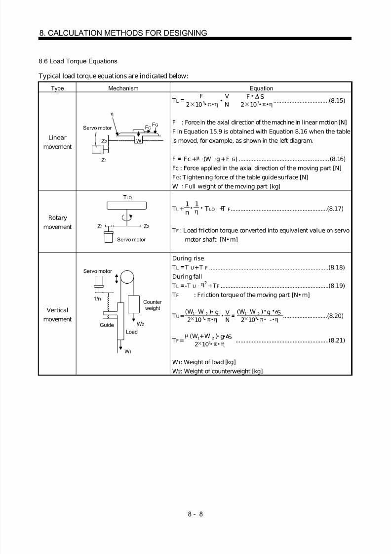
8/10/2019 Servo Motor - Instruction Manual SH(NA)-3181-D (03.00)
http://slidepdf.com/reader/full/servo-motor-instruction-manual-shna-3181-d-0300 361/368
8 - 8
8. CALCULATION METHODS FOR DESIGNING
8.6 Load Torque Equations
Typical load torque equations are indicated below:
Type Mechanism Equation
Linearmovement
Servo motor
W
Z1
FCFG
Z2
TL 2 10 3
FNV
2 10 3F S ..................................(8.15)
F : Force in the axial direction of the machine in linear motion [N]F in Equation 15.9 is obtained with Equation 8.16 when the tableis moved, for example, as shown in the left diagram.
F Fc + (W g + F G) .......................................................(8.16)Fc : Force applied in the axial direction of the moving part [N]F G : T ightening force of the table guide surface [N]W : Full weight of the moving part [kg]
Rotarymovement
Servo motor
Z1 Z2
TLO
TL + n1 1
TLO T F+ ...........................................................(8.17)
TF : Load friction torque converted into equivalent value on servomotor shaft [N•m]
Verticalmovement
Counterweight
Servo motor
W2
W1
1/n
LoadGuide
During rise TL T U + T F .........................................................................(8.18)During fall TL -T U 2
+ T F ..................................................................(8.19) TF : Fri ction torque of the moving part [N•m]
TU =2 10 3
(W1 - W 2 )NV
2 10 3g S(W1 - W 2 ) g
- ...........................(8.20)
TF =10 32
g(W1 + W 2 ) S .........................................................(8.21)
W1: Weight of load [kg]W2: Weight of counterweight [kg]

8/10/2019 Servo Motor - Instruction Manual SH(NA)-3181-D (03.00)
http://slidepdf.com/reader/full/servo-motor-instruction-manual-shna-3181-d-0300 362/368
8 - 9
8. CALCULATION METHODS FOR DESIGNING
8.7 Load Inertia Moment Equations
Typical load inertia moment equations are indicated below:
Type Mechanism Equation
Axis of rotation is on the cylindercenter
Axis of rotation
L
D1
D2
J LO =32
L (D - D )41
42 8
W (D + D )21
22 .........................(8.22)
ρ : Cylinder material density [kg/cm 3]L : Cylinder length [cm]D1 : Cylinder outside diameter [cm]D2 : Cylinder inside diameter [cm]W : Cylinder weight [kg]
Reference data: material densityI ron : 7.8 10 -3 [kg/cm 3]Aluminum : 2.7 10 -3 [kg/cm 3]
Copper : 8.96 10 -3 [kg/cm 3]
Cylinder
Axis of rotation is off the cylinder
Axis of rotation D
Rcenter
J LO 8W
(D + 8R )2 2 ..............................................................(8.23)
Square block
Axis of rotation
R
aa b
b J LO W3
a2 +b 2
+R 2 ..........................................................(8.24)
W : Square block weight [kg]a, b, R : Left diagram [cm]
Object whichmoves linearly
Servo motor V
WN
J L W600
V2
1W N 10V
2
W 20
2S ...............(8.25)
V : Speed of object moving linearly [mm/min]S : Moving distance of object moving linearly per servo
motor revolution [mm/rev]W : Object weight [kg]
Object that ishung with pulley
Servo motor
W
D J L W 2D
2
+ J p ..................................................................(8.26)
J P : Pulley inertia moment [kg cm 2]D : Pulley diameter [cm]W : Object weight [kg]
Converted loadLoad A
J A
J 31J B
N3
J 21
J 11
J 22 N2
N1
J L J 11 + (J 21 + J 22 + J A )N 1
N 22
+( J 31 +J B )N 1
N 32
................... (8.27)
J A , J B : Inertia moments of loads A, B [kg cm 2] J 11 to J 31 : Inertia moments [kg cm 2]
N1 to N 3 : Speed of each shaft [r/min]

8/10/2019 Servo Motor - Instruction Manual SH(NA)-3181-D (03.00)
http://slidepdf.com/reader/full/servo-motor-instruction-manual-shna-3181-d-0300 363/368
8 - 10
8. CALCULATION METHODS FOR DESIGNING
8.8 Precautions for Zeroing
When a general positioning unit is used, the sequence of events is as shown in the following figure.
ON
Actuator signal
When determining the ON duration of theactuator, consider the deceleration time sothat the speed reaches the creep speed.
Considering the variations of theactuator signal, adjust the actuatorso that it switches off near the centerof the High of the zero pulse signal.
Zero pulse signal
Zeroing speed V 1
Deceleration started by actuator signalCreep speed V 2
OFF
(1) When determining the ON duration of the actuator, consider the delay time of the control section andthe deceleration time so that the creep speed is attained. If the actuator signal switches off duringdeceleration, precise home position return cannot be performed.
ON duration of the actuator L D
Deceleration time t d
Zeroing speed V 1
Travel distance gained afterdetecting the zeroing dog untilthe creep speed is reached L 1
Control delaytime t 1
Creep speed V 2
Travel distance L1 in the chart can be obtained by Equation 8.28
L11
60 V1 t 1 + 1120 V1 t d 1 - V1
V22
+ 160 V1 T p....................................................................... (8.28)
ON duration of the actuator LD [mm] must be longer than L 1 obtained by Equation 8.28, as indicatedin Equation 8.29LD L 1 ...................................................................................................................................................... (8.29) where, V1, V2 : As shown in the chart [mm/min] t 1, t d : As shown in the chart [s] L1 : As shown in the chart [mm] LD : As shown in the chart [mm]

8/10/2019 Servo Motor - Instruction Manual SH(NA)-3181-D (03.00)
http://slidepdf.com/reader/full/servo-motor-instruction-manual-shna-3181-d-0300 364/368
8 - 11
8. CALCULATION METHODS FOR DESIGNING
(2) Set the end (OFF position) of the actuator signal at the middle of two ON positions (Lows) of the zeropulse signal. I f it is set near either ON position of the zero pulse signal, the positioning unit i s liable tomisdetect the zero pulse signal. In this case, a fault will occur, e.g. the home position will shift by onerevolution of the servo motor.
The zero pulse output position can be confirmed by OP (encoder Z-phase pulse) on the external I /Osignal display.
8.9 Selection Example
Speed of moving part during fast feed Vo 30000[mm/min]Command resolution 10[ µm] Travel 400[mm]Positioning time to within 1[s]Number of feeds 40[times/min]Operation cycle tf 1.5[s]
Gear ratio n 8/5Moving part weight W 60[kg]Drive system efficiency 0.8Friction coefficient 0.2Ball screw lead Pb 16[mm]Ball screw diameter 20[mm]Ball screw length 500[mm]Gear diameter (servo motor) 25[mm]Gear diameter (load shaft) 40[mm]
Machine specifications
Servomotor
Servoamplifier
Gear ratio 5:8
Gear face width 10[mm]
(1) Selection of control parametersSetting of electronic gear (command pulse multiplication numerator, denominator) There is the following relationship between the multiplication setting and travel per pulse ∆l .
8192 (gear ration)
(ball screw lead) CDV
CMX
When the above machining specifications are substituted in the above equation:
CDVCMX
10 16 10008192 8/5
10008192
Acceptable as CMX/CDV is within 1/20 to 20.
(2) Servo motor speed
NoPbVo n
1630000
58
3000[r/min]

8/10/2019 Servo Motor - Instruction Manual SH(NA)-3181-D (03.00)
http://slidepdf.com/reader/full/servo-motor-instruction-manual-shna-3181-d-0300 365/368
8 - 12
8. CALCULATION METHODS FOR DESIGNING
(3) Acceleration/deceleration time constant Tpsa Tpsd to -
Vo/60 -ts 0.05[s]
ts: settl ing time.(Here, this is assumed to be 0.15s.)
(4) Operation pattern
Servomotorspeed
[r/min]
3000
Time0.05
to=1.0
tf =1.5
0.05 tsTpsa Tpsd 0.15
[s]
(5) Load torque (converted into equivalent value on servo motor shaft) Travel per servo motor revolution
∆S P b 1n 16 58
10[mm]
TL2 10 3
W g S2 10 3 3.140.2 60 9.8 10
0.8 0.23[N m]

8/10/2019 Servo Motor - Instruction Manual SH(NA)-3181-D (03.00)
http://slidepdf.com/reader/full/servo-motor-instruction-manual-shna-3181-d-0300 366/368
8 - 13
8. CALCULATION METHODS FOR DESIGNING
(6) Load inertia moment (converted into equivalent value on servo motor shaft)Moving part
JL1 W 20
2S 1.52[kg cm 2]
Ball screw
JL2 32L D4 n
21 0.24[kg cm 2]
ρ 7.8 10 -3[kg cm 3]
Gear (servo motor shaft)
J L3 32 L D4 0.03[kg cm 2]
Gear (load shaft)
J L4 32L D4 n
21 0.8[kg cm 2]
Full load inertia moment (converted into equivalent value on servo motor shaft)
JL JL1 + J L2 + J L3 + J L4 1.9[kg cm 2]
(7) Temporary selection of servo motor Selection conditions1) Load torque servo motor's rated torque2) Full load inertia moment 30 servo motor inertia moment
From the above, the HC-MF23 (200W) is temporarily selected.
(8) Acceleration and deceleration torques Torque required for servo motor during acceleration
TMa(J L +J M ) No
9.55 10 4 Tpsa + T L 1.7[N m]
Torque required for servo motor during deceleration
TMd(J L+J M ) No
9.55 10 4 Tpsd + T L -1.2[N m]
The torque required for the servo motor during deceleration must be lower than the servo motor'smaximum torque.

8/10/2019 Servo Motor - Instruction Manual SH(NA)-3181-D (03.00)
http://slidepdf.com/reader/full/servo-motor-instruction-manual-shna-3181-d-0300 367/368
8 - 14
8. CALCULATION METHODS FOR DESIGNING
(9) Continuous effective load torque
Trms tf T Tpsa + T tc T T psd
2 2 2Ma L Md+
0.41[N m]
The continuous effective load torque must be lower than the servo motor's rated torque.
(10) Torque pattern
Torque
1.7[N m]
0.23
-1.2
Time[s]0.05 0.75 0.05
1.5
0.15
(11) Selection results The HC-MF23 servo motor and MR-J 2-20A servo amplifier are selected.1) Electronic gear setting
CMX 8192CDV 1000
2) During rapid feed Servo motor speed N o 3000 [r/min]
3) Acceleration/deceleration time constant Tpsa Tpsd 0.05[s]

8/10/2019 Servo Motor - Instruction Manual SH(NA)-3181-D (03.00)
http://slidepdf.com/reader/full/servo-motor-instruction-manual-shna-3181-d-0300 368/368
REVISIONS
* The manual number is given on the bottom left of the back cover.
Print Data * Manual Number Revision
May.,1998 SH(NA)3181-A First edition
Sep.,1998 SH(NA)3181-B HA-LH 11K2 to 22K2 addedHC-SF502(B), 702(B) addedHC-RF353(B), 503(B) addedHC-UF352(B), 502(B)/HC-UF73(B) addedUL/C-UL Standard: Flange size list modifiedSection 1.3: Terminal box type addedChapter 3: Overall changesSection 5.1: Applicable servo amplifier and regenerative brake duty added for
MR-H -N
Power supply capacity deletedSection 5.3: HC-MF's permissible speed changedSection 7.1.1 (2), (c), 2): HA-FF053BG1 1/5 inerti a moment changedSection 7.3: Reviewed due to overall changes to Chapter 3
Feb.,1999 SH(NA)3181-C HC-KF 23(B), 43(B) addedHC-AQ0135(B) to 0335(B) addedHA-L F30K24 to 55K24 addedHC-UF -S1 addedUL/C-UL Standard: Flange size list modifiedSection 1.1: Servo motor feature list modifiedSection 1.2, (2), (h): HC-KF, HC-AQ, HA-L F added to the models
Section 2.1: HC-K F, HC-AQ, HA-LF added to the listSection 2.3: Sentence modifiedSection 2.5: HC-K F, HC-AQ, HA-LF added to the listSection 2.6: HC-KF, HC-AQ, HA-L F addedSection 2.7: AdditionSection 3.1.4: HC-AQ addedSection 3.2: List modifiedSection 3.3: HC-AQ addedSection 5.1: HC-KF, HC-AQ, HA-L F added
Insulation class addedRegenerative brake duty changed: HC-SF121, HC-SF301,HC-RF503,HC-UF 72, HC-UF 152, HC-UF 23, HC-UF43, HC-UF73Rated current, maximum current changed: HC-SF702
Section 5.2: HC-KF, HC-AQ, HA-L F addedHC-UF73 modified
Section 5.3: HC-KF addedSection 6.1: HC-KF, HC-AQ addedSection 7.1.1: HC-UF73 modifi ed
HC-UF73B, HC-UF-S1, HC-KF, HC-AQ, HA-LF addedSection 7.1.2: HC-K F-UE added