ServiceManual - Arrakis Systemsarrakis-systems.com/pdfs/arc10-15servicemanual.pdf · 2011-07-06 ·...
31
ARC-10 & ARC-15 Service Manual A RRAKIS advanced radio Rev 1.0.4 Phone Pgm Aud Cue Talk to Caller Pgm Aud Cue Pgm Aud Cue Pgm Aud Cue Pgm Aud Cue Pgm Aud Cue Pgm Aud Cue Pgm Aud Cue Pgm Aud Cue Pgm Aud Cue Air Pgm Aud Monitor Head phone Advanced Radio Console Arrakis Systems Arrakis Systems inc. Monitor & Headphone Input Select Cue Pgm Aud Talk Pgm Aud Cue Pgm Aud Cue Pgm Aud Cue Pgm Aud Cue ARC-15 Mic Mic 1 Mic 2 Phone Pgm Aud Talk Talk to Caller Pgm Aud Talk Pgm Aud Cue Pgm Aud Cue Pgm Aud Cue Pgm Aud Cue Pgm Aud Cue Pgm Aud Cue Pgm Aud Cue Pgm Aud Cue Air Pgm Aud Monitor Head phone Advanced Radio Console Arrakis Systems Monitor & Headphone Input Select Cue ARC-10 Arrakis Systems inc. 1.1
Transcript of ServiceManual - Arrakis Systemsarrakis-systems.com/pdfs/arc10-15servicemanual.pdf · 2011-07-06 ·...
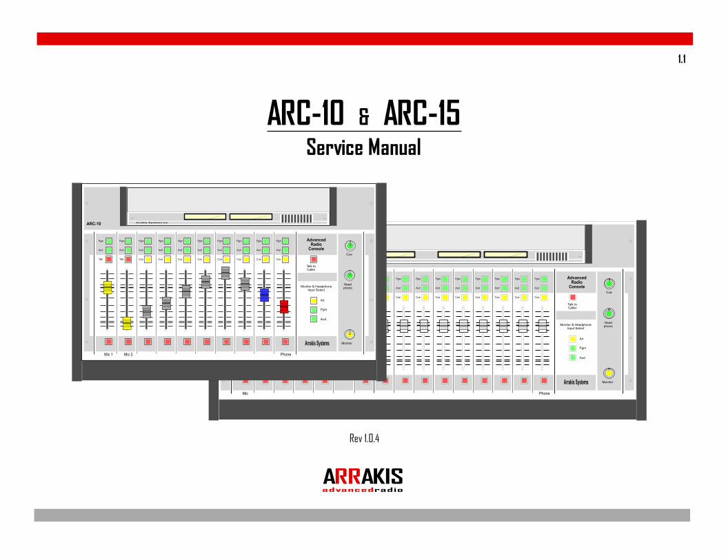
ARC-10 & ARC-15Service Manual
ARRAKISadvancedradio
Rev 1.0.4
Phone
Pgm
Aud
Cue
Talk toCaller
Pgm
Aud
Cue
Pgm
Aud
Cue
Pgm
Aud
Cue
Pgm
Aud
Cue
Pgm
Aud
Cue
Pgm
Aud
Cue
Pgm
Aud
Cue
Pgm
Aud
Cue
Pgm
Aud
Cue
Air
Pgm
Aud
Monitor
Headphone
AdvancedRadio
Console
Arrakis Systems
Arrakis Systems inc.
Monitor & HeadphoneInput Select
Cue
Pgm
Aud
Talk
Pgm
Aud
Cue
Pgm
Aud
Cue
Pgm
Aud
Cue
Pgm
Aud
Cue
ARC-15
Mic
Mic 1 Mic 2 Phone
Pgm
Aud
Talk
Talk toCaller
Pgm
Aud
Talk
Pgm
Aud
Cue
Pgm
Aud
Cue
Pgm
Aud
Cue
Pgm
Aud
Cue
Pgm
Aud
Cue
Pgm
Aud
Cue
Pgm
Aud
Cue
Pgm
Aud
Cue
Air
Pgm
Aud
Monitor
Headphone
AdvancedRadio
Console
Arrakis Systems
Monitor & HeadphoneInput Select
Cue
ARC-10 Arrakis Systems inc.
1.1
Arrakis Systems inc. is located at Arrakis Systems inc6604 Powell StreetLoveland, Colorado80538
Business Hours: 8:00am - 4:30pm mountain time
Contact: Voice: 970-461-0730Fax: 970-663-1010email: [email protected]: arrakis-systems.com
Having difficulty contacting Arrakis?Refer to the website at... www.arrakis-systems.com
for current contact information
How to contact Arrakis Systems
ARRAKISadvancedradio
1.2

16. A Product and Cart Combination should bemoved with care. Quick stops, excessive force,and uneven surfaces may cause the product andthe cart combination to overturn.17. Servicing. Refer all servicing to qualifiedservicing personnel.18. Damage Requiring Service. Unplug thisproduct from the wall AC outlet and referservicing to qualified service personnel underthe following conditions:a. When the AC cord or plug is damaged.b. If liquid has been spilled or objects havefallen into the product.c. If the product has been exposed to rain orwater.d. If the product does not operate normally(following operating instructions).e. If the product has been dropped ordamaged in any way.f. When the product exhibits a distinct changein performance. This indicates a need forservice.19. Replacement Parts. When replacement partsare required, be sure the service technician hasused replacement parts specified by themanufacturer or that have the samecharacteristics as the original parts. Unauthorizedsubstitutions may result in fire, electric shock, orother hazards.20. Safety Check. Upon completion of any repairsto this product, ask the service technician toperform safety checks to determine that theproduct is in proper operating condition.21. Cleaning. Do not use liquid cleaners or aerosolcleaners. Use only a damp cloth for cleaning.
1. Read All Instructions. All safety and operatinginstructions must be read before operating theproduct.2. Retain All Instructions. All safety andoperating instructions must be retained forfuture reference.3. Heed All Warnings. All warnings on theproduct and those listed in the operatinginstructions must be adhered to.4. Follow All Instructions. All operating andproduct usage instructions must be followed.5. Heat. This product must be situated away fromany heat sources such as radiators, heatregisters, stoves, or other products (includingpower amplifiers) that produce heat.6. Ventilation. Slots and openings in the productare provided for ventilation. They ensure reliableoperation of the product, keeping it fromoverheating. These openings must not beblocked nor covered during operation. Thisproduct should not be placed into a rack unlessproper ventilation is provided throughfollowing the manufacturer’s recommendedinstallation procedures.7. Water and Moisture. Do not use this productnear water—for example; near a bath tub, washbowl, kitchen sink or laundry tub; in a wetbasement; or near a swimming pool or the like.8. Attachments. Do not use any attachments notrecommended by the product manufactureras they may cause hazards.9. Power Sources. This product must beoperated from the type of power sourceindicated on the marking label and in theinstallation instructions. If you are not sure of
the type of power supplied to your facility,consult your local power company.10. Grounding and Polarization. This product isequipped with a polarized AC plug with integralsafety ground pin. Do not defeat the safetyground in any manner.11. Power Cord Protection. Power supply cordsmust be routed so that they are not likely to bewalked on nor pinched by items placed uponor against them. Pay particular attention to thecords at AC wall plugs and conveniencereceptacles, and at the point where the cordplugs into the product.12. Lightning. For added protection for thisproduct during a lightning storm, or when it isleft unattended and unused for long periods oftime, unplug it from the AC wall outlet. This willprevent damage to the product due tolightning and power line surges.13. Overloading. Do not overload AC wall outlets,extension cords, or integral convenience outletsas this can result in a fire or electric shock hazard.14. Object and Liquid Entry. Never push objectsof any kind into this product through openingsas they may touch dangerous voltage pointsor short-out parts that could result in a fire orelectric shock. Never spill liquid of any kind onthe product.15. Accessories. Do not place this product on anunstable cart, stand, tripod, bracket, or table. Theproduct may fall, causing serious damage to achild or adult, and serious damage to theproduct. Any mounting of the product needsto follow manufacturer’s installationinstructions.
S a f e t y I n s t r u c t i o n s1.3
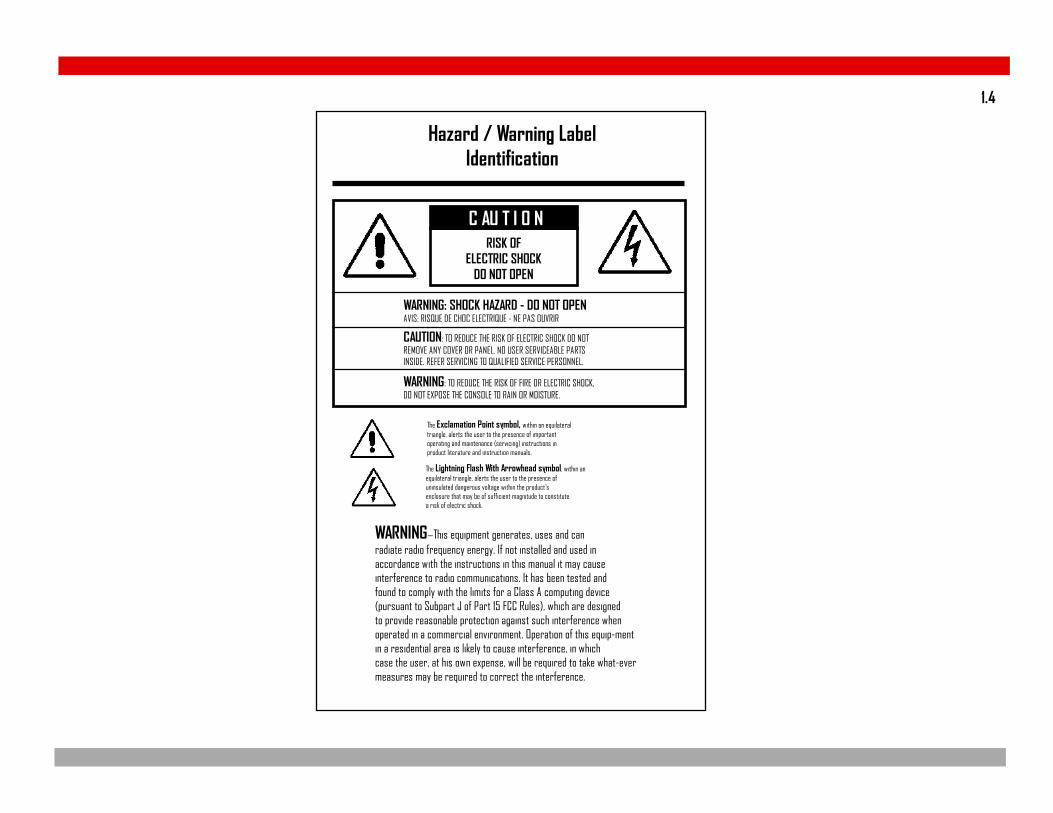
RISK OFELECTRIC SHOCK
DO NOT OPEN
WARNING—This equipment generates, uses and canradiate radio frequency energy. If not installed and used inaccordance with the instructions in this manual it may causeinterference to radio communications. It has been tested andfound to comply with the limits for a Class A computing device(pursuant to Subpart J of Part 15 FCC Rules), which are designedto provide reasonable protection against such interference whenoperated in a commercial environment. Operation of this equip-mentin a residential area is likely to cause interference, in whichcase the user, at his own expense, will be required to take what-evermeasures may be required to correct the interference.
The Exclamation Point symbol, within an equilateraltriangle, alerts the user to the presence of importantoperating and maintenance (servicing) instructions inproduct literature and instruction manuals.
WARNING: TO REDUCE THE RISK OF FIRE OR ELECTRIC SHOCK,DO NOT EXPOSE THE CONSOLE TO RAIN OR MOISTURE.
WARNING: SHOCK HAZARD - DO NOT OPENAVIS: RISQUE DE CHOC ELECTRIQUE - NE PAS OUVRIR
CAUTION: TO REDUCE THE RISK OF ELECTRIC SHOCK DO NOTREMOVE ANY COVER OR PANEL. NO USER SERVICEABLE PARTSINSIDE. REFER SERVICING TO QUALIFIED SERVICE PERSONNEL.
Hazard / Warning LabelIdentification
The Lightning Flash With Arrowhead symbol, within anequilateral triangle, alerts the user to the presence ofuninsulated dangerous voltage within the product’senclosure that may be of sufficient magnitude to constitutea risk of electric shock.
C AU T I O N
1.4

Warranty
This console carries a manufacturer‘s warranty subject to the following guidelines and limitations:
A) Except as expressly excluded herein, Arrakis Systems inc. (“Seller”) warrants equipment of its own manufacture against faulty workmanshipor the use of defective materials for a period of one (1) year from date of shipment to Buyer. The liability of the Seller under this Warranty is limited toreplacing, repairing or issuing credit (at the Seller’s discretion) for any equipment, provided that Seller is promptly notified in writing within five (5)days upon discovery of such defects by Buyer, and Seller‘s examination of such equipment shall disclose to its satisfaction that such defects existedat the time shipment was originally made by Seller, and Buyer returns the defective equipment to Seller’s place of business in Loveland, Colorado,packaging and transportation prepaid, with return packaging and transport guaranteed.
B) Equipment furnished by Seller, but manufactured by another, shall be warranted only to the extent provided by the other manufacturer.
C) Thermal filament devices (such as lamps and fuses) are expressly excluded from this warranty.
D) The warranty period on equipment or parts repaired or replaced under warranty shall expire upon the expiration date of the originalwarranty.
E) This Warranty is void for equipment which has been subject to abuse, improper installation, improper operation, improper or omitted mainte-nance, alteration, accident, negligence (in use, storage, transportation or handling), operation not in accordance with Seller‘s operation and serviceinstructions, or operation outside of the environmental conditions specified by Seller.
F) This Warranty is the only warranty made by Seller, and is in lieu of all other warranties, including merchantability and fitness for a particularpurpose, whether expressed or implied, except as to title and to the expressed specifications contained in this manual. Seller’s sole liability for anyequipment failure or any breach of this Warranty is as set forth in subparagraph A) above; Seller shall not be liable or responsible for any businessloss or interruption, or other consequential damages of any nature whatsoever, resulting from any equipment failure or breach of this warranty.
1.5
General Repair ConsiderationsWARNINGThe console should be repaired by qualified, professional, & experienced, audio technicians ONLY. Before beginning any type of repair oropening the console CALL Arrakis customer support for recommendations.
DESIGNED FOR MODULAR PART REPLACEMENTThe ARC series console is designed for modular replacement rather than repair. The power supply is external and plug in. The rotary faders are plug in. Most ICs are plug in, and a physical board layout is providedwith descriptions of the functions of each IC. ICs can be individually replaced to test for functionality. A small amount of disassembly is required. Diagrams on the following pages explain the required disassembly.
PC BOARD COMPONENT LEVEL REPAIRIf possible, PC board component level repair requiring soldering should be performed at the factory. In particular, replacement of slide faders and switches should be performed at the factory. If the repair mustbe made in the field, then extreme care must be taken to not damage the PC board or other components. Arrakis can not warranty non-factory service.
POWER SUPPLYThe power supply is a sealed module that must be replaced in whole if there is a problem.
REPEATED EQUIPMENT FAILURESIf a specific part of the console is failing regularly, it is likely that it is being subject to unusual stresses.Examples are;
(1) Switch or fader failure- rough physical treatment(2) Mic channel IC failure- static discharge to mic(3) Input op amp failure- lightning, power surge, or other transient on this cable(4) Output op amp failure- lightning, power surge, or other transient on this cable(5) Power Supply failure- lightening, power surge, or other transient on the AC power line
SUGGESTED REPAIR PROCEDURES(1) NO AUDIO OUT OF ONE INPUT CHANNEL- (Swap Cables) Be certain that the problem is in the console itself. If mic channel two doesn’t function but mic channel one functions properly, then plug the cable fromthe good mic into the channel that you suspect to be bad. If the channel that you suspect to be bad now functions, then the problem is external to the console and is in the source or the wiring. This is a very fastand easy way to test your system.(2) VU METERS MOVE BUT NO AUDIO OUT OF THE CONSOLE- The VU meters measure the actual output of the console itself. If the meters move but no audio is present, the problem is after the console outputand is in the following signal chain. Plug a set of headphones into the output of the console and listen to the Program output to confirm this.(3) LOUD LOW FREQUENCY HUM IN AUDIO- Many years ago this would mean a power supply failure. In today’s electronics, this is an installation problem such as a ground loop. To confirm the problem is not inthe console, remove ALL wiring from the console and connect a pair of headphones to the output you are testing. The hum should be absent. All wiring must be removed and headphones only used. A very commonproblem is for an audio power amp and speakers to create the ground loop with the console.(4) NO AUDIO OUT OF THE MONITORS- Be certain that the monitor system is not muted due to a mic channel being on or talkback being activated.
1.6
Opening the Console
WARNINGThe console should be repaired by qualified, professional, & experienced, audio technicians ONLY. Before beginning any type of repairor opening the console CALL Arrakis customer support for recommendations.
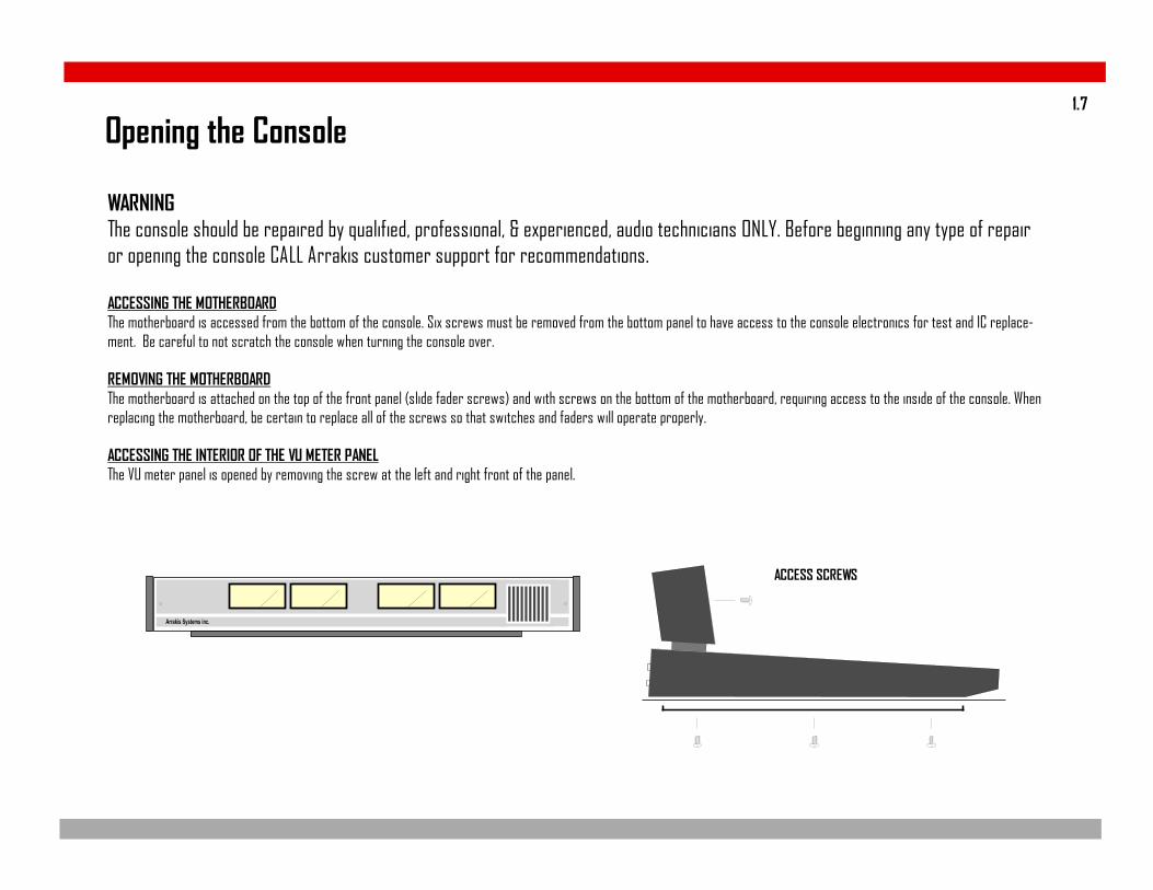
ACCESSING THE MOTHERBOARDThe motherboard is accessed from the bottom of the console. Six screws must be removed from the bottom panel to have access to the console electronics for test and IC replace-ment. Be careful to not scratch the console when turning the console over.
REMOVING THE MOTHERBOARDThe motherboard is attached on the top of the front panel (slide fader screws) and with screws on the bottom of the motherboard, requiring access to the inside of the console. Whenreplacing the motherboard, be certain to replace all of the screws so that switches and faders will operate properly.
ACCESSING THE INTERIOR OF THE VU METER PANELThe VU meter panel is opened by removing the screw at the left and right front of the panel.
ACCESS SCREWS
Arrakis Systems inc.
1.7
Replacing Slide Faders, Switches, and other partsSlide faders and switches are soldered onto the PC board and should be replaced at the factory if at all possible. The procedure requires proper tools, and itcan be difficult to remove the parts without damaging traces or pads on the PC board. Also, the switches are very sensitive to temperature and duration duringthe soldering process and can be electronically damaged or destroyed when being soldered. If a slide fader, switch, or other part must be replaced in the field,then extreme care must be taken.
Tools required:1) Hand held solder sucker (stranded solder wick is not suggested)2) Temperature controlled soldering iron with pencil tip (soldering guns should not be used)
Procedure:1) Suck the solder from all holes until the damaged component is entirely free from the PC board. Remove the damaged part.2) Place the new part onto the PC board. Slide faders and switches (and some other parts) ARE oriented and MUST be replaced in the correct orientation.3) Carefully solder the new part to the PC board.
a) Clean the tip of the soldering iron on a wet sponge.b) Tin the tip of the soldering iron (cover the tip of the soldering iron with a small amount of solder).c) Set the soldering iron to 734 degrees Fahrenheit (390 degrees celsius).d) Touch the tip of the ‘soldering iron’ to the junction of the PC board pad AND the component lead.e) Immediately touch the ‘solder’ to the junction of the soldering iron and the PC board pad.f) Flow only enough solder to fill the hole. Immediately remove the soldering iron from the part.g) Do not keep the soldering iron on the part for more than 2 seconds.h) Clean the solder rosin from the PC board if required. (See Note #1 below)
Note #1: Arrakis uses aqueous core (water soluble) solder that requires the solder joint to be cleaned by water after soldering. Aqueous core solder is acidicand must be cleaned so as to not damage the PC board over time. Rosin core solder is not water soluble and requires a flux remover if it is to be cleaned. Therosin residue however does not have to be removed for rosin core solder.
Warranty: Arrakis can only warranty service performed at the factory. All field service is performed at the customer’s risk.
1.8
Phone
Pgm
Aud
Cue
Talk toCaller
Pgm
Aud
Cue
Pgm
Aud
Cue
Pgm
Aud
Cue
Pgm
Aud
Cue
Pgm
Aud
Cue
Pgm
Aud
Cue
Pgm
Aud
Cue
Pgm
Aud
Cue
Pgm
Aud
Cue
Air
Pgm
Aud
Monitor
Headphone
AdvancedRadio
Console
Arrakis Systems
Arrakis Systems inc.
Monitor & HeadphoneInput Select
Cue
Pgm
Aud
Talk
Pgm
Aud
Cue
Pgm
Aud
Cue
Pgm
Aud
Cue
Pgm
Aud
Cue
ARC-15
Mic
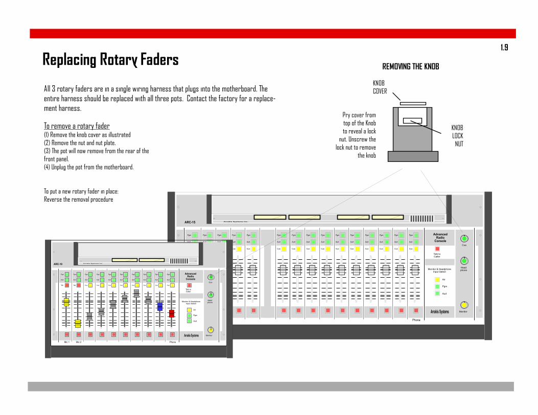
Replacing Rotary Faders
Pry cover fromtop of the Knobto reveal a lock
nut. Unscrew thelock nut to remove
the knob
KNOBCOVER
KNOBLOCK
NUT
All 3 rotary faders are in a single wiring harness that plugs into the motherboard. Theentire harness should be replaced with all three pots. Contact the factory for a replace-ment harness.
To remove a rotary fader(1) Remove the knob cover as illustrated(2) Remove the nut and nut plate.(3) The pot will now remove from the rear of thefront panel.(4) Unplug the pot from the motherboard.
To put a new rotary fader in place:Reverse the removal procedure
REMOVING THE KNOB
Mic 1 Mic 2 Phone
Pgm
Aud
Talk
Talk toCaller
Pgm
Aud
Talk
Pgm
Aud
Cue
Pgm
Aud
Cue
Pgm
Aud
Cue
Pgm
Aud
Cue
Pgm
Aud
Cue
Pgm
Aud
Cue
Pgm
Aud
Cue
Pgm
Aud
Cue
Air
Pgm
Aud
Monitor
Headphone
AdvancedRadio
Console
Arrakis Systems
Monitor & HeadphoneInput Select
Cue
ARC-10 Arrakis Systems inc.
1.9
Replacing ICsICs must be replaced with care. Most ICs in the console are socketed so that they can be replaced.
When replacing an IC, be careful to not bend legs under the IC or outside the socket. Be extremely careful to not shock an IC or the PC board with a static dis-charge. In some cases, you must use a grounded arm or anklet if there is a possibility of a static discharge.
In all cases, retain the old IC because it may be found to not be damaged.
1.10
Factory ServiceTechnical QuestionsArrakis Systems maintains a staff of friendly broadcast engineers, design engineers, and technicians who have many years of in depth field experience in broadcast-ing. All of our technical resources are available to you to answer installation questions, solve problems, and repair equipment. If you have a question or problem,please feel free to call us. We can not solve every problem, but our people are here to try.
Our customer support department is open from: 8AM - 4:30PM, Monday -Friday (except for Holidays)Voice: 970-461-0730Fax: 970-663-1010email: [email protected]
IMPORTANT: Collect calls will not be accepted
Warranty Service Procedure for the ARC console hardwareArrakis Systems assumes that its customers have on staff (or access to) competent technical personnel and adequate test equipment.
If a product fails, Arrakis will first seek to ascertain the problem over the phone and solve it at the modular replacement level where we find the specific part(s) that have failed and repair or replace them. This isthe least expensive and time consuming solution for you. Depending on the circumstances and at our discretion, Arrakis will replace the specific PC board suspected to be at fault. If replacing PC boards does notresolve the problem, then the console is to be returned to the factory where it will we repaired and returned to you. Repair time at the factory is normally two week days. If the customer chooses to repair theconsole in the field, then Arrakis will, at its sole discretion, send replacement parts under warranty. Arrakis can not warranty labor performed in the field.
Shipping- The customer is responsible for payment for shipping to the factory. Parts returned to the factory freight collect will be refused. Return shipping over and above the cost of UPS ground will be born bythe customer. In the case of international shipments, all cost of shipping and duties are born by the customer, both to and from the factory.
Under no circumstances will Arrakis replace a defective console with a replacement console.
IMPORTANT- Under no circumstances does Arrakis take any responsibility for non-factory technical expenses.
1.11
Warranty Replacement of PartsTo have a part replaced under warranty, you must:1) Provide a valid product serial number that is within the warranty period2) Contact the Arrakis customer service department and describe what parts need replacement and the circumstances of the failure. (The customer service departmentmay require on site test by your technician to confirm the part replacement is appropriate for your problem.)3) A Return Merchandise Authorization Number (RMA #) will be issued when a part s to be returned to the factory.4) Return ALL defective parts to the factory (shipping prepaid) to the attention of the “Customer Service Departent” with a letter including your name, address, call letters,serial number, date, and valid RMA #.5) Parts replaced under warranty will be shipped at Arrakis expense by UPS ground. Any expense over and above UPS ground will be born by the customer.
IMPORTANT- If the defective parts are not returned to the factory within 30 days, you will be invoiced for them and it will be assumed that they do not fall under warranty.Further customer service will be denied until the defective parts are returned of paid for.
Spare Parts (not provided with the ARC-10 or ARC-15 consoles)
A spare parts kit may be provided with the console. These parts are provided in case of emergency failure and normal infant mortality. These parts, when used to replacefailures, are not replaced under warranty.
Purchased PartsAn Arrakis customer may purchase spare or replacement parts from the factory. The cost of the parts will include a service charge, the cost for the parts, and the costof the shipping.
Parts may be purchased by:1) C.O.D. shipping2) Valid and approved Credit Card (below our current credit limit)3) Prepaid by company check (shipment after check clears the bank)4) Wire transfer of funds5) Through an Arrakis authorized dealer
Arrakis does not sell items on open account.
IMPORTANT- Non payment or late payment for parts will result in refusal of further customer service until the problem is resolved.
1.12
FADER
PGMSW
AUDSW
TALKSW
PGM AUD TALKON
Logic LogicLogic
FADER
PGMSW
AUDSW
CUESW
PGM AUD CUEON
Logic LogicLogic
FADER
PGMSW
AUDSW
CUESW
PGM AUD CUEON
Logic LogicLogic
FADER
PGMSW
AUDSW
CUESW
PGM AUD CUEON
Logic LogicLogic
Trim
Trim
TALK
Trim
FADER
MUTE
FADER
MUTE
FADER
PGM
AUD
AIR
LOGIC
FETSW
Trim
Trim
CODEC
Stt/Stp
Trim
Trim
Stt/Stp
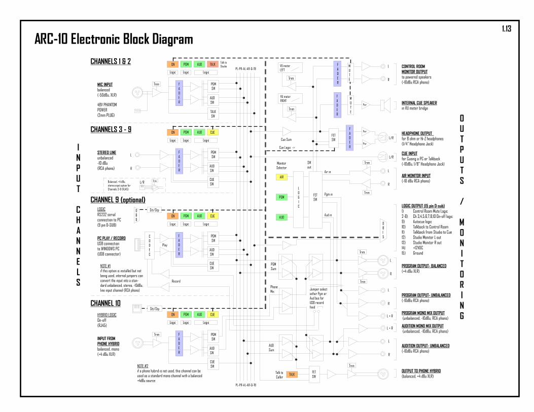
CONTROL ROOMMONITOR OUTPUTto powered speakers(-10dBu RCA phono)
INTERNAL CUE SPEAKERin VU meter bridge
HEADPHONE OUTPUTfor 8 ohm or Hi-Z headphones(1/4" Headphone Jack)
AIR MONITOR INPUT(-10 dBu RCA phono)
LOGIC OUTPUT (15 pin D-sub)1) Control Room Mute Logic2-8) Ch 3,4,5,6,7,8,10 On-off logic9) Autocue logic10) Talkback to Control Room11) Talkback from Studio to Cue12) Studio Monitor L out13) Studio Monitor R out14) +12VDC15) Ground
PROGRAM OUTPUT- BALANCED(+4 dBu XLR)
PROGRAM OUTPUT- UNBALANCED(-10dBu RCA phono)
AUDITION OUTPUT- UNBALANCED(-10dBu RCA phono)
OUTPUT TO PHONE HYBRID(balanced, +4 dBu XLR)
CUE INPUTfor Cueing a PC or Talkback(-10dBu, 1/8" Headphone Jack)
CHANNELS 1 & 2
MIC INPUTbalanced(-50dBu, XLR)
48V PHANTOMPOWER(2mm PLUG)
CHANNELS 3 - 9
STEREO LINEunbalanced-10 dBu(RCA phono)
CHANNEL 9 (optional)LOGICRS232 serialconnection to PC(9 pin D-SUB)
PC PLAY / RECORDUSB connectionto WINDOWS PC(USB connector)
CHANNEL 10
INPUT FROMPHONE HYBRIDbalanced, mono(+4 dBu XLR)
HYBRID LOGICOn-off(RJ45) AUDITION MONO MIX OUTPUT
(unbalanced, -10dBu, RCA phono)
PROGRAM MONO MIX OUTPUT(unbalanced, -10dBu, RCA phono)
FETSW
Cue Logic ->
Cue Sum
INPUT
CHANNELS
OUTPUTS
/
MONITORING
TrimBalanced, +4 dBu,stereo input option forChannels 3-8 (RJ45)
FETSW
DB9
DB15
Air in
Pgm in
Aud in
SWout
Record
Play
Pwr
Pwr
Pwr
VU meterLEFT
VU meterRIGHT
PGMSum
AUDSum
PhoneMix
MonitorSelector
Talk toCaller
Talk toStudio
PL-PR-AL-AR-Q-TB
PL-PR-AL-AR-Q-TB
L
R
L
R
L/R
L/R
L
R
L
R
L
R
L + R
L + R
L
R
L/R
NOTE #1if this option is installed but notbeing used, internal jumpers canconvert the input into a stan-dard unbalanced, stereo, -10dBu,line input channel (RCA phono)
NOTE #2if a phone hybrid is not used, this channel can beused as a standard mono channel with a balanced+4dBu source
Trim
Trim
Jumper selecteither Pgm orAud bus forUSB recordfeed
ARC-10 Electronic Block Diagram1.13

ARC-10 Parts Layout
+12Vled
-12Vled
-5Vled
+5Vled
Mic 1 amp(SSM2019)
Mic 2 amp(SSM2019)
Mic 1In
Mic 2In
48Vphntmpower
CH 3In
CH4In
CH 5In
CH 6In
CH7In
CH 8In
USBPGMOut (L)
PGMOut (R)
PhoneIn
PhoneOut
PhoneLogic
PGMOut
AUDOut
MonoOut
MonOut
AirIn
CH 9In
CueIn
DCPower
MuteFET Sw
(CD4053)
MonitorSelectFET Sw(CD4052)
HeadphoneAutocue
FET Sw(CD4053) Phone
TalkbackFET Sw(CD4053)
MeterHousing
CableConn
VolumeControl
CableConn
CueSpeaker
Amp(LM386)
HeadphoneAmpLeft
(LM386)
HeadphoneAmp
Right(LM386)
Summing amps
PgmAud
Cue
MicTalkback
Remote Logic Cable
Mon Sel LgcQuad ‘AND’ gate(74AC08)
Mon Sel LgcDual ‘D’ flip flop(74AC74)
AIR In amp &trimpots
PGMunbalOut
AUDunbalOut
MonoMixOut
MonitorOutVU
meterdrivers
RS232 Cable
RS232 LogicTransistors PGM
L outPGMR out
PhoneOut
Phone LogicReed relays
& Transistors
USB Codec(PCM2900)
12MHzXstal
CodecRecordFilter
PhoneIn
CodecOutputFilter
CH 3In
CH 4In
CH 5In
CH 6In
CH 7In
CH 8In
Channel Input Preamps
CH 1fader
makeupgainamp
CH 2fader
makeupgainamp
CH 3fader
makeupgainamp
CH 4fader
makeupgainamp
CH 5fader
makeupgainamp
CH 6fader
makeupgainamp
CH 7fader
makeupgainamp
CH 8fader
makeupgainamp
CH 9fader
makeupgainamp
CH 10fader
makeupgainamp
CH 1On Lgc
(CD4049)
CH 2On Lgc
(CD4049)
CH 3On Lgc
(CD4049)
CH 4On Lgc
(CD4049)
CH 5On Lgc
(CD4049)
CH 6On Lgc
(CD4049)
CH 7On Lgc
(CD4049)
CH 8On Lgc
(CD4049)
CH 9On Lgc
(CD4049)
CH 10On Lgc
(CD4049)
CH 1 FET SwP-A-Q
(CD4053)
CH 2 FET SwP-A-Q
(CD4053)
CH 3 FET SwP-A-Q
(CD4053)
CH 4 FET SwP-A-Q
(CD4053)
CH 5 FET SwP-A-Q
(CD4053)
CH 6 FET SwP-A-Q
(CD4053)
CH 7 FET SwP-A-Q
(CD4053)
CH 8 FET SwP-A-Q
(CD4053)
CH 9 FET SwP-A-Q
(CD4053)
CH 10 FET SwP-A-Q
(CD4053)
CH 1P-A-Q Lgc(CD4049)
CH 2P-A-Q Lgc(CD4049)
CH 3P-A-Q Lgc(CD4049)
CH 4P-A-Q Lgc(CD4049)
CH 5P-A-Q Lgc(CD4049)
CH 6P-A-Q Lgc(CD4049)
CH 7P-A-Q Lgc(CD4049)
CH 8P-A-Q Lgc(CD4049)
CH 9P-A-Q Lgc(CD4049)
CH 10P-A-Q Lgc(CD4049)
MonitorSW amp
PhoneSW amp
PGMmixamp
AUDmixamp
Mix the Phonechannel
with the MainOutput buses
Talk
Air
Pgm
Aud
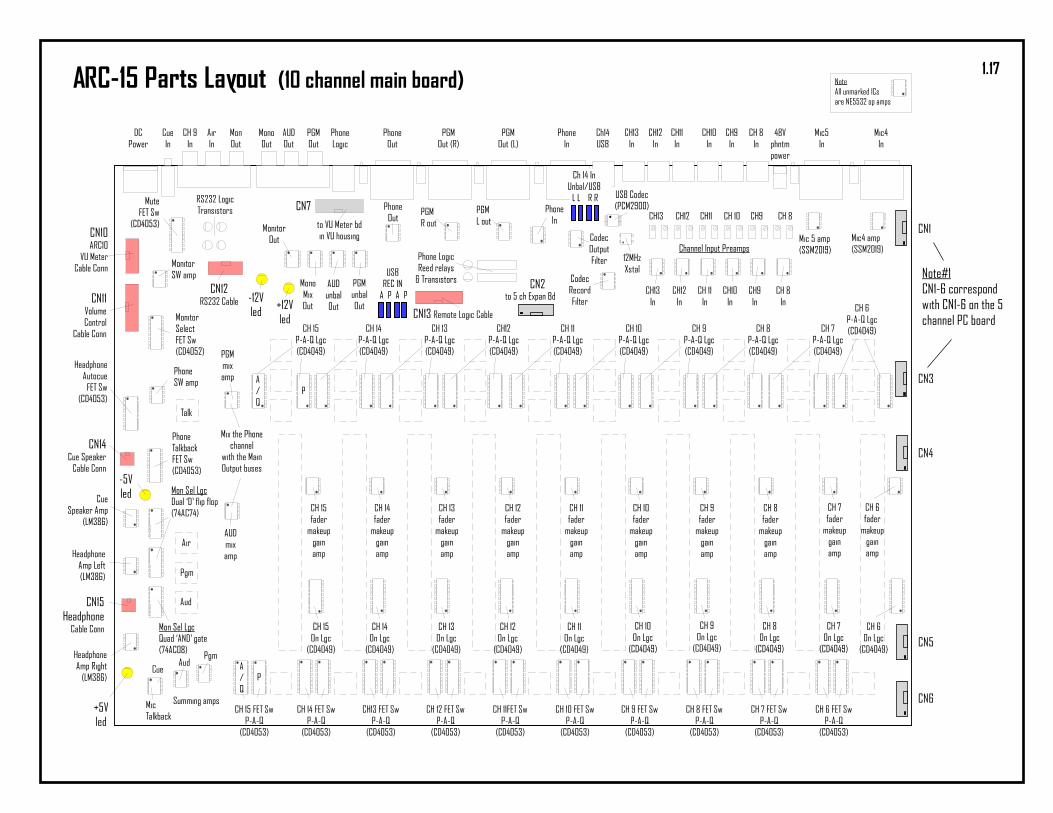
NoteAll unmarked ICsare NE5532 op amps
CH 3CH 4CH 5CH 6CH 7CH 8Trimpots: ARC-10BP only
MuteCh 2 Ch 1
Ch 9 InUnbal/USB
L L R R
USBREC IN
A P A P
A/Q
P
A/Q
P
CN10
CN11
CN14
CN15
CN12 CN13
1.14

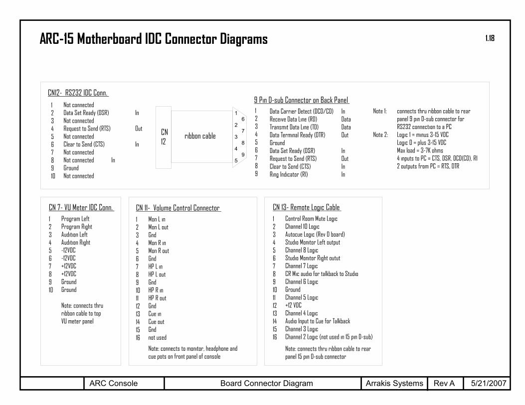
Board Connector Diagram 5/21/2007Rev AARC Console Arrakis Systems
12345678910111213141516
Control Room Mute LogicChannel 10 LogicAutocue Logic (Rev D board)Studio Monitor Left outputChannel 8 LogicStudio Monitor Right oututChannel 7 LogicCR Mic audio for talkback to StudioChannel 6 LogicGroundChannel 5 Logic+12 VDCChannel 4 LogicAudio Input to Cue for TalkbackChannel 3 LogicChannel 2 Logic (not used in 15 pin D-sub)
Note: connects thru ribbon cable to rearpanel 15 pin D-sub connector
CN 13- Remote Logic Cable
12345678910111213141516
Mon L inMon L outGndMon R inMon R outGndHP L inHP L outGndHP R inHP R outGndCue inCue outGndnot used
Note: connects to monitor, headphone andcue pots on front panel of console
CN 11- Volume Control Connector
123456789
Data Carrier Detect (DCD/CD) InReceive Data Line (RD) DataTransmit Data Line (TD) DataData Terminal Ready (DTR) OutGroundData Set Ready (DSR) InRequest to Send (RTS) OutClear to Send (CTS) InRing Indicator (RI) In
CN12- RS232 IDC Conn.
1
2
3
4
5
6
7
8
9
ARC-10 Motherboard IDC Connector Diagrams
12345678910
Not connectedNot connectedPgm Left VUPgm Right VU+5VDC+5VDCGroundGroundNot connectedControl Room Mute Logic
Note: connects thruribbon cable to topVU meter panel
CN10- VU Meter IDC Conn.
Note 1: connects thru ribbon cable to rearpanel 9 pin D-sub connector forRS232 connection to a PC
Note 2: Logic 1 = minus 3-15 VDCLogic 0 = plus 3-15 VDCMax load = 3-7K ohms4 inputs to PC = CTS, DSR, DCD(CD), RI2 outputs from PC = RTS, DTR
12345678910
Not connectedData Set Ready (DSR) InNot connectedRequest to Send (RTS) OutNot connectedClear to Send (CTS) InNot connectedNot connected InGroundNot connected
CN12
ribbon cable
9 Pin D-sub Connector on Back Panel
1.15

ARC-15 Electronic Block Diagram
FADER
PGMSW
AUDSW
TALKSW
PGM AUD TALKON
Logic LogicLogic
FADER
PGMSW
AUDSW
CUESW
PGM AUD CUEON
Logic LogicLogic
FADER
PGMSW
AUDSW
CUESW
PGM AUD CUEON
Logic LogicLogic
FADER
PGMSW
AUDSW
CUESW
PGM AUD CUEON
Logic LogicLogic
Trim
Trim
TALK
Trim
FADER
MUTE
FADER
MUTE
FADER
PGM
AUD
AIR
LOGIC
FETSW
Trim
Trim
CODEC
Stt/Stp
Trim
Trim
Stt/Stp
CONTROL ROOMMONITOR OUTPUTto powered speakers(-10dBu RCA phono)
INTERNAL CUE SPEAKERin VU meter bridge
HEADPHONE OUTPUTfor 8 ohm or Hi-Z headphones(1/4" Headphone Jack)
AIR MONITOR INPUT(-10 dBu RCA phono)
LOGIC OUTPUT (15 pin D-sub)1) Control Room Mute Logic
(for On Air light)2-7) Ch 2,3,4,5,13,15 On-off logic8) Talkback audio to Studio9) Talkback audio from Studio
(into Cue bus)10) Autocue logic (for TB)11) Ch 2 Cue logic for TB12) Studio Monitor L out13) Studio Monitor R out14) +12VDC15) Ground
PROGRAM OUTPUT- BALANCED(+4 dBu XLR)
PROGRAM OUTPUT- UNBALANCED(-10dBu RCA phono)
AUDITION OUTPUT- UNBALANCED(-10dBu RCA phono)
OUTPUT TO PHONE HYBRID(balanced, +4 dBu XLR)
CUE INPUTfor Cueing a PC or Talkback(-10dBu, 1/8" Headphone Jack)
MIC CHANNELS
MIC INPUTbalanced(-50dBu, XLR)
48V PHANTOMPOWER(2mm PLUG)
LINE CHANNELS
STEREO LINE
CHANNEL 14LOGICRS232 serialconnection to PC(9 pin D-SUB)
PC PLAY / RECORDUSB connectionto WINDOWS PC(USB connector)
CHANNEL 15
INPUT FROMPHONE HYBRIDbalanced, mono(+4 dBu XLR)
HYBRID LOGICOn-off(RJ45) AUDITION MONO MIX OUTPUT
(unbalanced, -10dBu, RCA phono)
PROGRAM MONO MIX OUTPUT(unbalanced, -10dBu, RCA phono)
FETSW
Cue Logic ->
Cue Sum
INPUT
CHANNELS
OUTPUTS
/
MONITORING
Trim
Balanced, +4 dBu,stereo inputs(RJ45)
FETSW
DB9
DB15
Air in
Pgm in
Aud in
SWout
Record
Play
Pwr
Pwr
Pwr
VU meterLEFT
VU meterRIGHT
PGMSum
AUDSum
PhoneMix
MonitorSelector
Talk toCaller
Talk toStudio
PL-PR-AL-AR-Q-TB
PL-PR-AL-AR-Q-TB
L
R
L
R
L/R
L/R
L
R
L
R
L
R
L + R
L + R
L/R
NOTE #1if this option is installed but notbeing used, internal jumpers canconvert the input into a stan-dard unbalanced, stereo, -10dBu,line input channel (RCA phono)
NOTE #2if a phone hybrid is not used, this channel can beused as a standard mono channel with a balanced+4dBu source
1.16
+12Vled
-12Vled
-5Vled
+5Vled
Mic4 amp(SSM2019)
Mic 5 amp(SSM2019)
Mic4In
Mic5In
48Vphntmpower
CH 8In
CH9In
CH10In
CH11In
CH12In
CH13In
Ch14USB
PGMOut (L)
PGMOut (R)
PhoneIn
PhoneOut
PhoneLogic
PGMOut
AUDOut
MonoOut
MonOut
AirIn
CH 9In
CueIn
DCPower
MuteFET Sw
(CD4053)
MonitorSelectFET Sw(CD4052)
HeadphoneAutocue
FET Sw(CD4053)
PhoneTalkbackFET Sw(CD4053)
CN11VolumeControl
Cable Conn
CueSpeaker Amp
(LM386)
HeadphoneAmp Left(LM386)
HeadphoneAmp Right
(LM386)
Summing amps
PgmAud
Cue
MicTalkback
CN13 Remote Logic Cable
Mon Sel LgcQuad ‘AND’ gate(74AC08)
Mon Sel LgcDual ‘D’ flip flop(74AC74)
PGMunbalOut
AUDunbalOut
MonoMixOut
MonitorOut
CN12RS232 Cable
RS232 LogicTransistors PGM
L outPGMR out
PhoneOut
Phone LogicReed relays
& Transistors
USB Codec(PCM2900)
12MHzXstal
CodecRecordFilter
PhoneIn
CodecOutputFilter
CH 8In
CH9In
CH10In
CH 11In
CH12In
CH13In
Channel Input Preamps
CH 6fader
makeupgainamp
CH 7fader
makeupgainamp
CH 8fader
makeupgainamp
CH 9fader
makeupgainamp
CH 10fader
makeupgainamp
CH 11fader
makeupgainamp
CH 12fader
makeupgainamp
CH 13fader
makeupgainamp
CH 14fader
makeupgainamp
CH 15fader
makeupgainamp
CH 6On Lgc
(CD4049)
CH 7On Lgc
(CD4049)
CH 8On Lgc
(CD4049)
CH 9On Lgc
(CD4049)
CH 10On Lgc
(CD4049)
CH 11On Lgc
(CD4049)
CH 12On Lgc
(CD4049)
CH 13On Lgc
(CD4049)
CH 14On Lgc
(CD4049)
CH 15On Lgc
(CD4049)
CH 6 FET SwP-A-Q
(CD4053)
CH 7 FET SwP-A-Q
(CD4053)
CH 8 FET SwP-A-Q
(CD4053)
CH 9 FET SwP-A-Q
(CD4053)
CH 10 FET SwP-A-Q
(CD4053)
CH 11FET SwP-A-Q
(CD4053)
CH 12 FET SwP-A-Q
(CD4053)
CH13 FET SwP-A-Q
(CD4053)
CH 14 FET SwP-A-Q
(CD4053)
CH 15 FET SwP-A-Q
(CD4053)
CH 6P-A-Q Lgc(CD4049)CH 7
P-A-Q Lgc(CD4049)
CH 8P-A-Q Lgc(CD4049)
CH 9P-A-Q Lgc(CD4049)
CH 10P-A-Q Lgc(CD4049)
CH 11P-A-Q Lgc(CD4049)
CH12P-A-Q Lgc(CD4049)
CH 13P-A-Q Lgc(CD4049)
CH 14P-A-Q Lgc(CD4049)
CH 15P-A-Q Lgc(CD4049)
MonitorSW amp
PhoneSW amp
PGMmixamp
AUDmixamp
Mix the Phonechannel
with the MainOutput buses
Talk
Air
Pgm
Aud
NoteAll unmarked ICsare NE5532 op amps
CH 8CH9CH 10CH11CH12CH13
Ch 14 InUnbal/USB
L L R R
USBREC IN
A P A P
A/Q
P
A/Q
P
to 5 ch Expan Bd
to VU Meter bdin VU housing
ARC-15 Parts Layout (10 channel main board)
CN1
CN3
CN4
CN5
CN6
Note#1CN1-6 correspondwith CN1-6 on the 5channel PC board
CN2
CN7
CN14Cue Speaker
Cable Conn
CN15Headphone
Cable Conn
CN10ARC10
VU MeterCable Conn
1.17
Board Connector Diagram 5/21/2007Rev AARC Console Arrakis Systems
12345678910111213141516
Control Room Mute LogicChannel 10 LogicAutocue Logic (Rev D board)Studio Monitor Left outputChannel 8 LogicStudio Monitor Right oututChannel 7 LogicCR Mic audio for talkback to StudioChannel 6 LogicGroundChannel 5 Logic+12 VDCChannel 4 LogicAudio Input to Cue for TalkbackChannel 3 LogicChannel 2 Logic (not used in 15 pin D-sub)
Note: connects thru ribbon cable to rearpanel 15 pin D-sub connector
CN 13- Remote Logic Cable12345678910
Program LeftProgram RightAudition LeftAudition Right-12VDC-12VDC+12VDC+12VDCGroundGround
Note: connects thruribbon cable to topVU meter panel
CN 7- VU Meter IDC Conn.12345678910111213141516
Mon L inMon L outGndMon R inMon R outGndHP L inHP L outGndHP R inHP R outGndCue inCue outGndnot used
Note: connects to monitor, headphone andcue pots on front panel of console
CN 11- Volume Control Connector
123456789
Data Carrier Detect (DCD/CD) InReceive Data Line (RD) DataTransmit Data Line (TD) DataData Terminal Ready (DTR) OutGroundData Set Ready (DSR) InRequest to Send (RTS) OutClear to Send (CTS) InRing Indicator (RI) In
CN12- RS232 IDC Conn.
1
2
3
4
5
6
7
8
9
ARC-15 Motherboard IDC Connector Diagrams
Note 1: connects thru ribbon cable to rearpanel 9 pin D-sub connector forRS232 connection to a PC
Note 2: Logic 1 = minus 3-15 VDCLogic 0 = plus 3-15 VDCMax load = 3-7K ohms4 inputs to PC = CTS, DSR, DCD(CD), RI2 outputs from PC = RTS, DTR
12345678910
Not connectedData Set Ready (DSR) InNot connectedRequest to Send (RTS) OutNot connectedClear to Send (CTS) InNot connectedNot connected InGroundNot connected
CN12
ribbon cable
9 Pin D-sub Connector on Back Panel
1.18
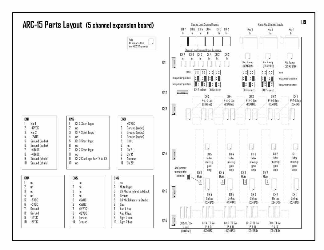
ARC-15 Parts Layout (5 channel expansion board)
Mic 1 amp(SSM2019)
Mic 2 amp(SSM2019)
Mic 1In
Mic 2In
CH 2In
CH 3In
CH 4In
CH 5In
CH 6In
CH 2In
CH 3In
CH 4In
CH 5In
CH 6In
CH 7In
Stereo Line Channel Input Preamps
CH 1fader
makeupgainamp
CH 2fader
makeupgainamp
CH 3fader
makeupgainamp
CH 4fader
makeupgainamp
CH 5fader
makeupgainamp
CH 1On Lgc
(CD4049)
CH 2On Lgc
(CD4049)
CH 3On Lgc
(CD4049)
CH 4On Lgc
(CD4049)
CH 5On Lgc
(CD4049)
CH 1 FET SwP-A-Q
(CD4053)
CH 2 FET SwP-A-Q
(CD4053)
CH 3 FET SwP-A-Q
(CD4053)
CH 4 FET SwP-A-Q
(CD4053)
CH 1P-A-Q Lgc(CD4049)
CH 2P-A-Q Lgc(CD4049)
CH 3P-A-Q Lgc(CD4049)
CH 4P-A-Q Lgc(CD4049)
CH 5P-A-Q Lgc(CD4049)
Mic 3In
CH 7In
Mic 3 amp(SSM2019)
none
mic jumper position
line jumper position
none
mic jumper position
line jumper position
CH 6 select CH 5 select CH 3 select CH 2 select
CH 5Mute
CH 4Mute
CH 3Mute
CH 2Mute
Add jumperto mute the
channel
Stereo Line Channel Inputs Mono Mic Channel Inputs
CH 5 FET SwP-A-Q
(CD4053)
CN1
CN2
CN3
CN5
CN6
CN4
NoteAll unmarked ICsare NE5532 op amps
CN112345678910
Mic 1+12VDCMic 2-12VDCGround (audio)Ground (audio)+48VDC+48VDCGround (shield)Ground (shield
CN212345678910
Ch 5 Start logicncCh 4 Start LogicncCh 3 Start logicncCh 2 Start logicncCh 2 Cue Logic for TB to CRnc
CN312345678910
+12VDCGorund (audio)Ground (audio)Ground (audio)CH1 LncCh 2 LCh 1RAutocueCh 2R
CN412345678910
ncncncnc+5VDC+5VDCGroundGorund-5VDC-5VDC
CN512345678910
ncncncnc+5VDC+5VDC+14VDC+12VDCGorundGround
CN612345678910
ncMute logicCR Mic to Hybrid talkbackGroundCR MicTakback to StudioCueAud L busAud R busPgm L busPgm R bus
1.19
+
5532U1B
76
5
_
10pF
+47uF
2.2K
32.4K
4.7K
50K
+
5532U1A
12
3
_
10pF
+47uF
2.2K
32.4K
4.7K
50K
+
5532U2A
12
3
_
10pF
+47uF
2.2K
32.4K
4.7K
50K
+
5532U2B
76
5
_
10pF
+47uF
2.2K
32.4K
4.7K
50K
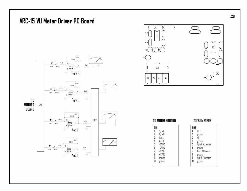
ARC-15 VU Meter Driver PC Board
Pgm R
Pgm L
Aud L
Aud R
CN1
CN1
CN2
U1
U2
PL PR AL AR
CN112345678910
Pgm LPgm RAud LAud R-12VDC-12VDC+12VDC+12VDCgroundground
TO MOTHERBOARD TO VU METERS
CN212345678910
NCgroundNCgroundPgm L VU metergroundAud L VU metergroundAud R VU meterground
CN2
TOMOTHER
BOARD
1.20

Main Buss Diagram 5/21/2007Rev AARC Console Arrakis Systems
123456789
PLPRALARCUECR MICgndCR Mic to Studio MonitorCR MUTE Logic
Main Preamp Mixing Bus
PL (w phone)PR (w phone)AL (w phone)AR (w phone)PL (wo phone)PR (wo phone)AL (wo phone)AR (wo phone)CUECR MicLogicTo Caller
Vertical Bus
SummingAmps
InputChannels
InputChannels
InputChannels
InputChannels
InputChannels
Ext L inExt R InCR Mon LCR Mon RPC ch On LogicALARPLPRPhone outStu Mon LStu Mon RCR Mic
IO Bus12345678910111213
12345678910111213
In
Out
Input Connectors and Amps
P/A/Q/Mic
10 Ch Motherboard Bus Block DiagramThis diagram docu-ments the basic bustracing on themotherboard. Output Connectors and Amps
1.21
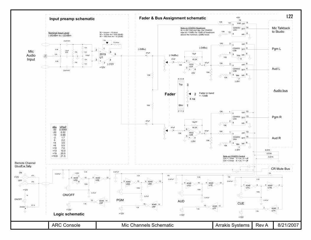
+
2019U1
74
6
2
3
_ 18
+48VDC
Mic Channels Schematic 8/21/2007Rev AARC Console Arrakis Systems
+
+
+
5532U2A
12
3
_40.2K
10pF
+
CD4053U4C
12
13
14
11
X/Y
ctrlY
X 6inh
CD4053U3B
5
3
4
9
X/Y
ctrlY
X 6inh
CD4053U4B
5
3
4
9
X/Y
ctrlY
X 6inh
47uF
47uF
10K
4049U5D
109 4049U5E
1211
2.2k0.047uF
100k
0.47uF
+
+
+
5532U2B
76
5
_40.2K
10pFF
+
CD4053U3A
2
1
15
10
X/Y
ctrlY
X 6inh
CD4053U4A
2
1
15
10
X/Y
ctrlY
X 6inh
47uF
47uF
10K
Vdd
+5V
Vee
(-)5V
Vee
(-)5V
Fader
4049U5F
15 14
1.0k
4049U6D
109 4049U6E
1211
2.2k
0.047uF
100k
0.47uF
4049U6F
15 14
1.0k
4049U7D
109 4049U7E
1211
2.2k0.047uF
100k
0.47uF
4049U7F
15 14
1.0k
4049U7C
67 4049U7B
45
2.2k0.047uF
100k
0.47uF
4049U7A
2 3
1.0k
Mic Talkbackto Studio
Pgm L
Aud L
Pgm R
Aud R
10k10k
ON/OFFPGM AUD
CUE
+12V
22.1k2N3904
+12V
ON
OFF
ON/OFF
475
475
1k
Vss8
7
16
7
1
+12V
8
+12V
+12V+12V
+12V
10k
6.81K
6.81K
6.81K
4 3 3 4
2 1 1 2
3
2
1
4 na
Top
Btm
Remote ChannelOn-off w Tally
100
6.8k
6.8k
22uF, 63V
22uF63V
22uF, 63V
10k
10k
12V
12V
12V
12V
150pF
10 ohms1.0k
Rf = trimpot + 10 ohmsRf = 10 then Av= 1000 (60dB)Rf = 1000 then Av= 10 (20dB)
Audio bus
47uF
10K
10K
10K
10K
10K
47uF
10K
10K
10K
10K
10K
(-)12V+12V
8
4
+5V
(-)5V
Note on CD4053 ControlCtrl = 1 then Y = on, X = offCtrl = 0 then X = on, Y = off
Fader & Bus Assignment schematicInput preamp schematic
Logic schematic
(-14dBu)
(-2dBu)
Note on CD4053 HeadroomAt +(-)5V Vdd and Vee, the CD4053clips at +13dBU for 15dB of headroomabove the nominal (-)2dBU level.
(-2dBu)
Nominal Input Level(-)62dBm to (-)22dBm
CR Mute Bus
10K
10K
10K
10K
dBu-50-20-10-20
+4+8
+10+13+19
+19.8
VPtoP0.0069
0.220.691.72.23.55.57.0
10.020.021.5
Fader in hand= -12dB
MicAudioInput
1.22

+
5532U1A
12
3
_22.1K
10pF
10K
+
5532U1B
76
5
_22.1K
10pF
10K
Left
Right
-10dBu Unbalanced Stereo Input Channel Schematic 8/21/2007Rev AARC Console Arrakis Systems
+
+
+
5532U2A
12
3
_40.2K
10pF
+
CD4053U4C
12
13
14
11
X/Y
ctrlY
X 6inh
CD4053U3B
5
3
4
9
X/Y
ctrlY
X 6inh
CD4053U4B
5
3
4
9
X/Y
ctrlY
X 6inh
47uF
47uF
10K
4049U5D
109 4049U5E
1211
2.2k0.047uF
100k
0.47uF
+
+
+
5532U2B
76
5
_40.2K
10pFF
+
CD4053U3A
2
1
15
10
X/Y
ctrlY
X 6inh
CD4053U4A
2
1
15
10
X/Y
ctrlY
X 6inh
47uF
47uF
10K
Vdd
+5V
Vee
(-)5V
Vee
(-)5V
Fader
4049U5F
15 14
1.0k
4049U6D
109 4049U6E
1211
2.2k
0.047uF
100k
0.47uF
4049U6F
15 14
1.0k
4049U7D
109 4049U7E
1211
2.2k0.047uF
100k
0.47uF
4049U7F
15 14
1.0k
4049U7C
67 4049U7B
45
2.2k0.047uF
100k
0.47uF
4049U7A
2 3
1.0k
Cue
Pgm L
Aud L
Pgm R
Aud R
10k10k
ON/OFFPGM AUD
CUE
+12V
22.1k2N3904
+12V
ON
OFF
ON/OFF
475
475
1k
Vss8
7
16
7
1
+12V
8
+12V
+12V+12V
+12V
10k
6.81K
6.81K
6.81K
4 3 3 4
2 1 1 2
3
2
1
4 na
Top
Btm
Remote ChannelOn-off w Tally
Audio bus
47uF
10K
10K
10K
10K
10K
47uF
10K
10K
10K
10K
10K
8
4
+5V
(-)5V
Note on CD4053 ControlCtrl = 1 then Y = on, X = offCtrl = 0 then X = on, Y = off
Fader & Bus Assignment schematicInput preamp schematic
Logic schematic
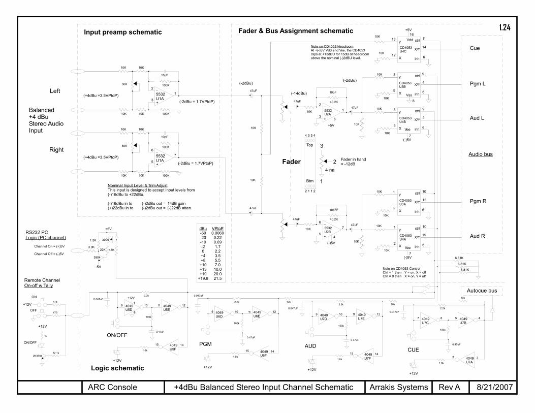
(-10dBu)(-2dBu)
(-14dBu)
(-2dBu)
Note on CD4053 HeadroomAt +(-)5V Vdd and Vee, the CD4053clips at +13dBU for 15dB of headroomabove the nominal (-)2dBU level.
Autocue bus
1.5K
22K 47K
3904
+5V
3.9K
-5V
3906
RS232 PCLogic (PC channel)
Channel On = (+)5V
Channel Off = (-)5V
10K
10K
10K
10K
(Av = 7dB)
(-10dBu = 0.7VPtoP)
(-2dBu = 1.7VPtoP)
dBu-50-20-10-20
+4+8
+10+13+19
+19.8
VPtoP0.0069
0.220.691.72.23.55.57.0
10.020.021.5
Fader in hand= -12dB
Unbalanced-10dBuStereo AudioInput
1.23
Left
Right
+4dBu Balanced Stereo Input Channel Schematic 8/21/2007Rev AARC Console Arrakis Systems
+
+
+
5532U2A
12
3
_40.2K
10pF
+
CD4053U4C
12
13
14
11
X/Y
ctrlY
X 6inh
CD4053U3B
5
3
4
9
X/Y
ctrlY
X 6inh
CD4053U4B
5
3
4
9
X/Y
ctrlY
X 6inh
47uF
47uF
10K
4049U5D
109 4049U5E
1211
2.2k0.047uF
100k
0.47uF
+
+
+
5532U2B
76
5
_40.2K
10pFF
+
CD4053U3A
2
1
15
10
X/Y
ctrlY
X 6inh
CD4053U4A
2
1
15
10
X/Y
ctrlY
X 6inh
47uF
47uF
10K
Vdd
+5V
Vee
(-)5V
Vee
(-)5V
Fader
4049U5F
15 14
1.0k
4049U6D
109 4049U6E
1211
2.2k
0.047uF
100k
0.47uF
4049U6F
15 14
1.0k
4049U7D
109 4049U7E
1211
2.2k0.047uF
100k
0.47uF
4049U7F
15 14
1.0k
4049U7C
67 4049U7B
45
2.2k0.047uF
100k
0.47uF
4049U7A
2 3
1.0k
Cue
Pgm L
Aud L
Pgm R
Aud R
10k10k
ON/OFFPGM AUD
CUE
+12V
22.1k2N3904
+12V
ON
OFF
ON/OFF
475
475
1k
Vss8
7
16
7
1
+12V
8
+12V
+12V+12V
+12V
10k
6.81K
6.81K
6.81K
4 3 3 4
2 1 1 2
3
2
1
4 na
Top
Btm
Remote ChannelOn-off w Tally
Audio bus
47uF
10K
10K
10K
10K
10K
47uF
10K
10K
10K
10K
10K
8
4
+5V
(-)5V
Note on CD4053 ControlCtrl = 1 then Y = on, X = offCtrl = 0 then X = on, Y = off
Fader & Bus Assignment schematicInput preamp schematic
Logic schematic
(-2dBu)
(-14dBu)
(-2dBu)
Note on CD4053 HeadroomAt +(-)5V Vdd and Vee, the CD4053clips at +13dBU for 15dB of headroomabove the nominal (-)2dBU level.
Autocue bus
1.5K
22K 47K
3904
+5V
3.9K
-5V
3906
RS232 PCLogic (PC channel)
Channel On = (+)5V
Channel Off = (-)5V
10K
10K
10K
10K
dBu-50-20-10-20
+4+8
+10+13+19
+19.8
VPtoP0.0069
0.220.691.72.23.55.57.0
10.020.021.5
Fader in hand= -12dB
+
5532U1A
12
3
_100K
10pF
10K
100K10K
10K
10K
50K
(+4dBu =3.5VPtoP)(-2dBu = 1.7VPtoP)
+
5532U1A
76
5
_100K
10pF
10K
100K10K
10K
10K
50K
(+4dBu =3.5VPtoP)(-2dBu = 1.7VPtoP)
Nominal Input Level & TrimAdjustThis input is designed to accept input levels from(-)16dBu to +22dBu.
(-)16dBu in to (-)2dBu out = 14dB gain(+)22dBu in to (-)2dBu out = (-)22dB atten.
Balanced+4 dBuStereo AudioInput
1.24

+
5532U1A
12
3
_100K
10pF
10K
100K10K
10K
10K
Telephone Hybrid Input Channel Schematic 8/21/2007Rev AARC Console Arrakis Systems
+
+
+
5532U2A
12
3
_40.2K
10pF
+
CD4053U4C
12
13
14
11
X/Y
ctrlY
X 6inh
CD4053U3B
5
3
4
9
X/Y
ctrlY
X 6inh
CD4053U4B
5
3
4
9
X/Y
ctrlY
X 6inh
47uF
47uF
10K
4049U5D
109 4049U5E
1211
2.2k0.047uF
100k
0.47uF
+
+
+
5532U2B
76
5
_40.2K
10pFF
+
CD4053U3A
2
1
15
10
X/Y
ctrlY
X 6inh
CD4053U4A
2
1
15
10
X/Y
ctrlY
X 6inh
47uF
47uF
10K
Vdd
+5V
Vee
(-)5V
Vee
(-)5V
Fader
4049U5F
15 14
1.0k
4049U6D
109 4049U6E
1211
2.2k
0.047uF
100k
0.47uF
4049U6F
15 14
1.0k
4049U7D
109 4049U7E
1211
2.2k0.047uF
100k
0.47uF
4049U7F
15 14
1.0k
4049U7C
67 4049U7B
45
2.2k0.047uF
100k
0.47uF
4049U7A
2 3
1.0k
Cue
Pgm
Aud
10k10k
ON/OFFPGM AUD
CUE
+12V
22.1k2N3904
+12V
ON
OFF
ON/OFF
475
475
1k
Vss8
7
16
7
1
+12V
8
+12V
+12V+12V
+12V
10k
6.81K
6.81K
6.81K
4 3 3 4
2 1 1 2
3
2
1
4 na
Top
Btm
Remote ChannelOn-off w Tally
PhoneChannel
(Output section)47uF
10K
4.7K
10K
4.7K
10K
47uF
10K
4.7K
10K
4.7K
10K
8
4
+5V
(-)5V
Note on CD4053 ControlCtrl = 1 then Y = on, X = offCtrl = 0 then X = on, Y = off
Fader & Bus Assignment schematicInput preamp schematic
Logic schematic
(-2dBu)
(-14dBu)
(-2dBu)
Note on CD4053 HeadroomAt +(-)5V Vdd and Vee, the CD4053clips at +13dBU for 15dB of headroomabove the nominal (-)2dBU level.
50K
Nominal Input Level & TrimAdjustThis input is designed to accept input levels from(-)16dBu to +22dBu.
(-)16dBu in to (-)2dBu out = 14dB gain(+)22dBu in to (-)2dBu out = (-)22dB atten.
Autocue bus
22K
+
22K
47K
2N3904
10uF 1N914
+12V
100
Hybrid ControlLogic
START
STOP
22K
+
22K
47K
2N3904
10uF 1N914
+12V
100
10K
10K
10K
10K
(+4dBu =3.5VPtoP)(-2dBu = 1.7VPtoP)
dBu-50-20-10-20
+4+8
+10+13+19
+19.8
VPtoP0.0069
0.220.691.72.23.55.57.0
10.020.021.5
Fader in hand= -12dB
nc
nc
Audio bus
Balanced+4 dBuStereo AudioInput
1.25
1
2
3
4
5
6
7
8
9
10
11
12
13
14
D+
D-
VBUS
DGNDU
HID0
HID1
HID2
SEL0
SEL1
VCCCI
AGNDC
VINL
VINR
VCOM
SSPND
VDDI
DGND
DOUT
DIN
VCCXI
AGNDX
XTI
XTO
VCCP2I
AGNDP
VCCP1I
VOUTL
VOUTR
28
27
26
25
24
23
22
21
20
19
18
17
16
15
PCM2900
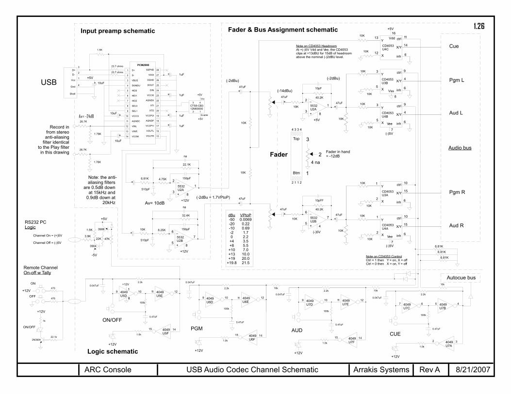
USB Audio Codec Channel Schematic 8/21/2007Rev AARC Console Arrakis Systems
+
+
+
5532U2A
12
3
_40.2K
10pF
+
CD4053U4C
12
13
14
11
X/Y
ctrlY
X 6inh
CD4053U3B
5
3
4
9
X/Y
ctrlY
X 6inh
CD4053U4B
5
3
4
9
X/Y
ctrlY
X 6inh
47uF
47uF
10K
4049U5D
109 4049U5E
1211
2.2k0.047uF
100k
0.47uF
+
+
+
5532U2B
76
5
_40.2K
10pFF
+
CD4053U3A
2
1
15
10
X/Y
ctrlY
X 6inh
CD4053U4A
2
1
15
10
X/Y
ctrlY
X 6inh
47uF
47uF
10K
Vdd
+5V
Vee
(-)5V
Vee
(-)5V
Fader
4049U5F
15 14
1.0k
4049U6D
109 4049U6E
1211
2.2k
0.047uF
100k
0.47uF
4049U6F
15 14
1.0k
4049U7D
109 4049U7E
1211
2.2k0.047uF
100k
0.47uF
4049U7F
15 14
1.0k
4049U7C
67 4049U7B
45
2.2k0.047uF
100k
0.47uF
4049U7A
2 3
1.0k
Cue
Pgm L
Aud L
Pgm R
Aud R
10k10k
ON/OFFPGM AUD
CUE
+12V
22.1k2N3904
+12V
ON
OFF
ON/OFF
475
475
1k
Vss8
7
16
7
1
+12V
8
+12V
+12V+12V
+12V
10k
6.81K
6.81K
6.81K
4 3 3 4
2 1 1 2
3
2
1
4 na
Top
Btm
Remote ChannelOn-off w Tally
Audio bus
47uF
10K
10K
10K
10K
10K
47uF
10K
10K
10K
10K
10K
8
4
+5V
(-)5V
Note on CD4053 ControlCtrl = 1 then Y = on, X = offCtrl = 0 then X = on, Y = off
Fader & Bus Assignment schematicInput preamp schematic
Logic schematic
(-14dBu)
(-2dBu)
Note on CD4053 HeadroomAt +(-)5V Vdd and Vee, the CD4053clips at +13dBU for 15dB of headroomabove the nominal (-)2dBU level.
(-2dBu)
1.5K
+ 1uF
+
+
+
1uF
1uF
1uF
+5V
+
+
+
10uF
10uF
23.7 ohms
23.7 ohms
10uF
+
5532U2A
12
3
_
22.1K
150pF4.75K
8
+12V
+6.81K
510pF
na
+
5532U2B
76
5
_
32.4K
150pF8.25K
8
+12V
+10K
510pF
na
USB
2 1
3 4
+5VVcc
Enable
+5V
CTS5-CB312M00000
1
D+
D-
Vcc
Gnd
Shell
4
2
3
Autocue bus
1.5K
22K 47K
3904
+5V
3.9K
-5V
3906
RS232 PCLogic
Channel On = (+)5V
Channel Off = (-)5V
10K
10K
10K
10K
Av= 10dB(-2dBu = 1.7VPtoP)
dBu-50-20-10-20
+4+8
+10+13+19
+19.8
VPtoP0.0069
0.220.691.72.23.55.57.0
10.020.021.5
Fader in hand= -12dB
26.7K
1.78K
Av= -24dB
26.7K
1.78K
Record infrom stereoanti-aliasing
filter identicalto the Play filterin this drawing
Note: the anti-aliasing filters
are 0.5dB downat 15kHz and
0.9dB down at20kHz
1.26
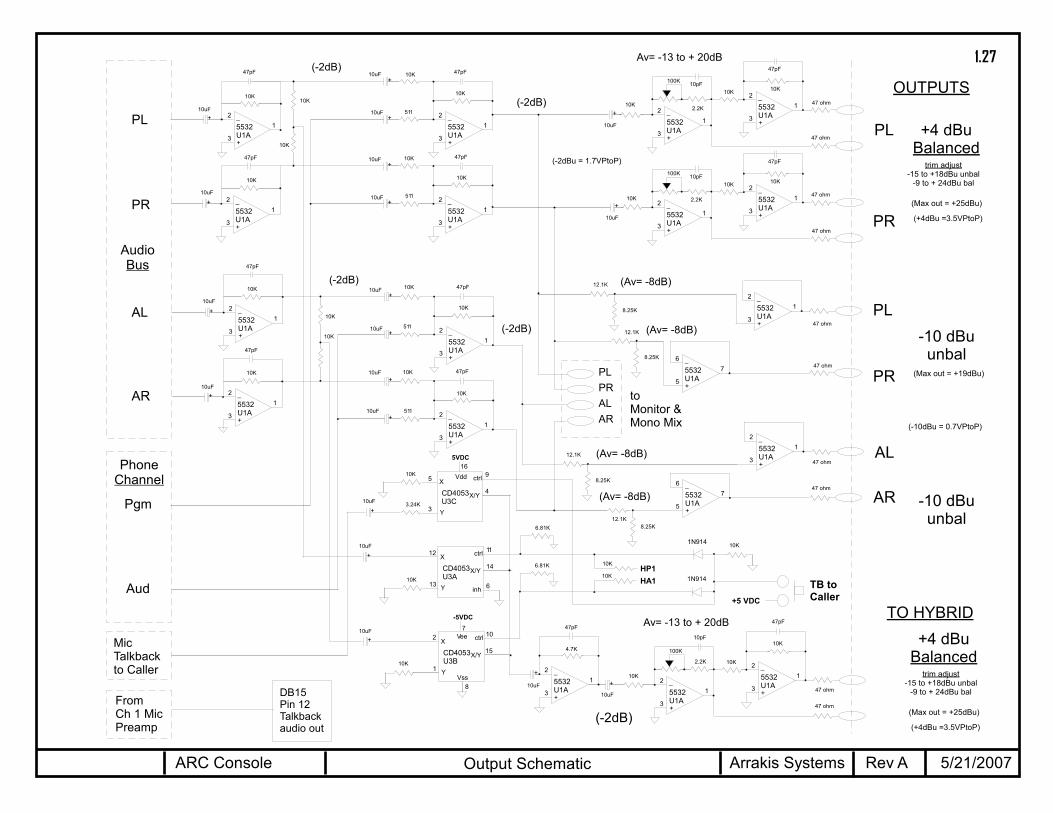
Output Schematic 5/21/2007Rev AARC Console Arrakis Systems
+
5532U1A
12
3
_10K
47pF
10K
+
5532U1A
12
3
_
10pF
+
5532U1A
12
3
_
47pF
+10uF
+
5532U1A
12
3
_10K
47pF
10K
+
5532U1A
12
3
_
10pF
+
5532U1A
12
3
_
+
5532U1A
76
5
_
PL
PL
PR
PR
AL
AR
+
5532U1A
12
3
_
10K
47pF
10K
+
5532U1A
12
3
_
10pF
TO HYBRID
+4 dBuBalanced
-10 dBuunbal
+
5532U1A
12
3
_
47pF
+10uF
+
5532U1A
12
3
_
47pF
+10uF
+
5532U1A
12
3
_
47pF
+10uF
+
5532U1A
12
3
_
47pF
+10uF
+10uF
+
5532U1A
12
3
_
47pF
+10uF
+10uF
+
5532U1A
12
3
_
47pF
+
+10uF
+
5532U1A
12
3
_
47pF
+10uF
+10uF
+
10uF
+
10uF
+
10uF
-10 dBuunbal
PL
PR
AL
AR
AudioBus
OUTPUTS
Pgm
Aud
CD4053U3A
13
12
14
11
X/Y
ctrlX
Y 6inh
+
CD4053U3B
1
2
15
10
X/Y
ctrlX
Y
Vee
-5VDC
+
+5 VDC
TB toCaller
MicTalkbackto Caller
PhoneChannel
PLPRALAR
toMonitor &Mono Mix
8Vss
7
+
5532U1A
12
3
_
+
5532U1A
76
5
_
+
5532U1A
12
3
_
4.7K
47pF
+
10K
10K
10K
10K
10K
511
10K
10K
10K
511
10K
10K
10K
511
10K
511
10K
10K
10K
10K
10K
10K
10uF
10uF
10uF
10K
100K
2.2K
6.81K
47 ohm
47 ohm
47 ohm
47 ohm
10K
10K
2.2K
2.2K
47 ohm
47 ohm
47 ohm
47 ohm
47 ohm
47 ohm
(-2dB)
(-2dB)
Av= -13 to + 20dB
(-2dB)
(-2dB)
(-2dB)
Av= -13 to + 20dB
10uF
100K
100Ktrim adjust
-15 to +18dBu unbal-9 to + 24dBu bal
12.1K
8.25K
12.1K
8.25K
12.1K
8.25K
12.1K8.25K
(Av= -8dB)
(Av= -8dB)
(Av= -8dB)
(Av= -8dB)
(Max out = +19dBu)
(Max out = +25dBu)
(-2dBu = 1.7VPtoP)
(-10dBu = 0.7VPtoP)
(+4dBu =3.5VPtoP)
+4 dBuBalanced
trim adjust-15 to +18dBu unbal
-9 to + 24dBu bal
(Max out = +25dBu)
(+4dBu =3.5VPtoP)
CD4053U3C
3
4
9
X/Y
ctrlX
Y
Vdd
5VDC16
3.24K
510K
+10uF
FromCh 1 MicPreamp
10K
10K
10KHP1HA1
6.81K
1N914
1N914
DB15Pin 12Talkbackaudio out
1.27

Monitor Schematic 5/21/2007Rev AARC Console Arrakis Systems
+
5532U1A
12
3
_22K
10pF
L
R
CRMonitorOutput(-10dBu)
CD4053U4C
13
12
14
11
X/Y
ctrlX
Y 6inh
Vdd
5VDC
+ OUTPUTS
PLPRALAR
+
5532U1A
12
3
_22K
47pF
6.8K
+
CD4052U1
16
7
152
3L IO
9B
Vee8
Vss
Vdd
L1 IOR1 IO
6 inh
145 L2 IO
R2 IO
10A
121
13R IO
L3 IOR3 IO
114 L4 IO
R4 IO
(-)5VDC
(+)5VDC
msb
lsb
+
5532U1A
12
3
_
47pF
+10uF
+
5532U1A
12
3
_
47pF
+10uF
+
5532U1A
76
5
_22K
47pF
6.8K
+
+10uF
+
+
+
+
+
5532U1A
12
3
_
47pF
+10uF
+
+
5532U1A
76
6
_
10pF
+
47uF
+
LM386U1
6
4
5
2
3
_
+
18
+
+47uF
+330uF
+
LM386U1
6
4
5
2
3
_
+
18
+
+47uF
+330uF
+
5532U1A
76
5
_22K
10pF
CD4053U4B
3
5
4
9
X/Y
ctrlX
Y 6inh
+10uF
CD4053U4A
1
2
15
10
X/Y
ctrlX
Y 6inh
(-)5VDC
+10uF
CueSpeaker
L
R
Headphonejack
CR MuteLogicBus
CueAudioBus
Air MonInput
L
R
74AC08U3A
14
7
31
+
2
74AHC74U1B
14+
8
912 D
13RD
SDQ
Q11
CP
10
+
74AC08U3B
14
7
64
+
5
74AHC74U2A 6
52 D
1RD
SDQ
Q3
CP
4
+
74AC08U3D
14
7
1112
+
13
74AHC74U2B
14+
7
8
912 D
13RD
SDQ
Q11
CP
10
+
Ext
Pgm
Aud+
Vee
Vss
74AC08U3C
89
10
Unused7
NA
16
7
8
10= air01= pgm00= aud
(0 = X, 1 = Y input)
CD4053U9C
13
12
14
11
X/Y
ctrlX
Y 6inh
Vdd
5VDC
+
CD4053U9B
3
5
4
9
X/Y
ctrlX
Y 6inh
+
(-)5VDC
Vee
16
7
Vss8
(0 = X, 1 = Y input)
10K
10K
10K
10K
10K
10K
10uF
10uF
10uF
10K
10K
10K10K
10uF
470
470
470
2.2K
32.4K
50K
50K
Av = (-)8dB to +10dB
(-2dBu)
(-12 to +6dBu)
(-2dBu)
(-2dBu)
(-2dBu)
(-14dBu)10K
10K
10K
10K
100K
10K
(Av= +7dB)
10K
6.81K
10
.047uF2 ohm1/2W
2 ohm1/2W
10
.047uF
+
LM386U1
6
4
5
2
3
_
+
18
+
+330uF
10
.047uF2 ohm1/2W
22.1k2N3904
100 ohm1/2W
(Av = 26dB)
(Av = 26dB)
(+5V PtoP = +7dBu)4.7K
50K
+
5532U1A
12
3
_
10pF
+
47uF
2.2K
32.4K
4.7K
50K
(0VU on meter = 2.9VPtoP = 2.6dBu)
(Av = 4.8dB)
(-2dBu = 1.7VPtoP)
(-10dBu = 0.7VPtoP)
200K
200K
100K
100K
100K
Mute = +12VDC
10K
10K
+4.7K
10K
2.2K10uF
2 ohm+12VDC
DB15Pin 14
+12VDC
DB15Pin 1CR MuteLogic forOn AirLight
DB15 Pin 10 Studio Monitor Left Audio outputDB15 Pin 11 Studio Monitor Right Audio output
fromOutput
Section
DB15Pin 2AutocueLogic In
DB15Pin 15Talkbackin to Cue Autocue
bus
NOTE #1: The meter circuits on the 10 channelPC board are used for the ARC-10 only. TheARC-15 has VU meter driver boards located onthe VU Meters themselves in the VU housing.
VUright
VUleft
1.28

Mono Mixdown Schematic 5/21/2007Rev AARC Console Arrakis Systems
Pgm mono mix(-)10dBu
OUTPUTSPLPRALAR
+
5532U1A
12
3
_3.9K
10pF
10K
10K
Aud mono mix(-)10dBu
fromOutput
Schematic
10K
+
5532U1B
76
5
_3.9K
10pF
10K
10K10K
47
47
(-2dBu = 1.7VPtoP)
dBu-50-20-10-20
+4+8
+10+13+19
+19.8
VPtoP0.0069
0.220.691.72.23.55.57.0
10.020.021.5
3.29K
3.29K
1.29
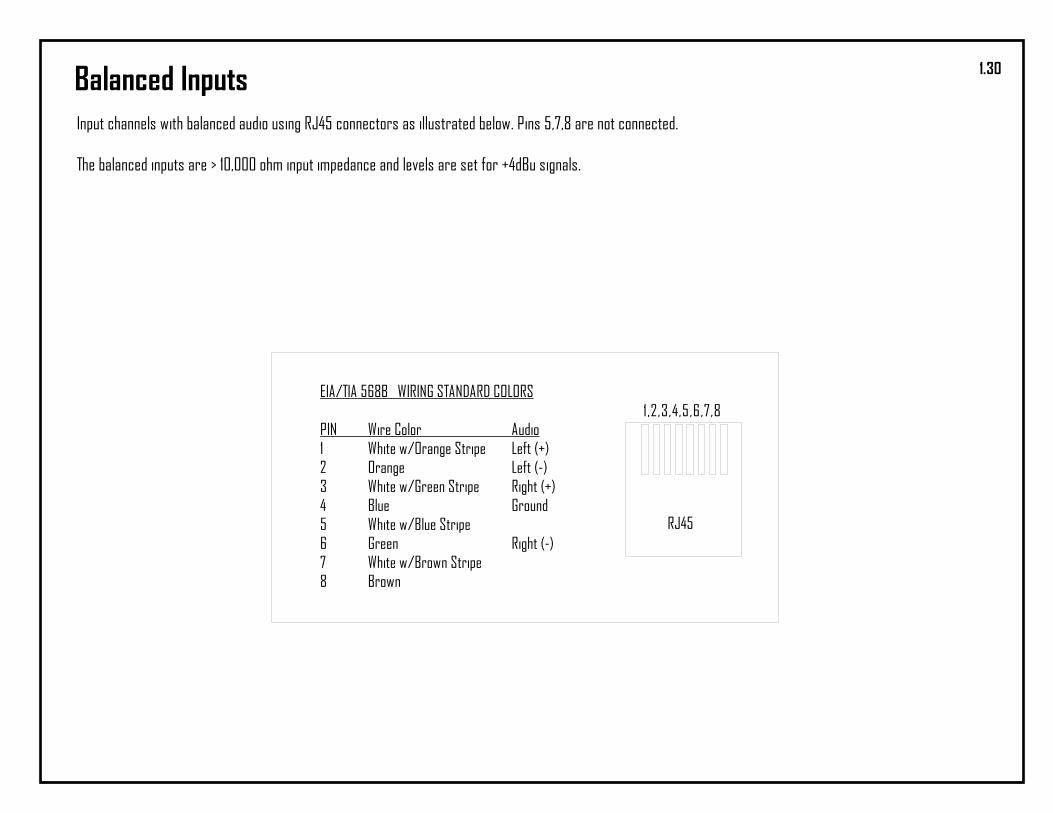
Balanced InputsInput channels with balanced audio using RJ45 connectors as illustrated below. Pins 5,7,8 are not connected.
The balanced inputs are > 10,000 ohm input impedance and levels are set for +4dBu signals.
EIA/TIA 568B WIRING STANDARD COLORS
PIN Wire Color Audio1 White w/Orange Stripe Left (+)2 Orange Left (-)3 White w/Green Stripe Right (+)4 Blue Ground5 White w/Blue Stripe6 Green Right (-)7 White w/Brown Stripe8 Brown
1,2,3,4,5,6,7,8
RJ45
1.30

Console LogicThe DB-15 connector on the rear panel of the console has the logic & audiosignals required for supporting a talk studio and controlling the starting &stopping of sources.
8 7 6 5 4 3 2 1
15 14 13 12 11 10 9
DB15 CONNECTOR PINOUT (Solder Cup)
CONSOLE BACK PANEL VIEW
PIN123456789101112131415
DESCRIPTIONControl Room Mute Logic (will switch to Pin 13 ground)Autocue Logic In (switch to ground to turn on)Channel Eight Logic (+12VDC channel on, 0VDC channel off)Channel Seven Logic (+12VDC channel on, 0VDC channel off)Channel Six Logic (+12VDC channel on, 0VDC channel off)Channel Five Logic (+12VDC channel on, 0VDC channel off)Channel Four Logic (+12VDC channel on, 0VDC channel off)Channel 3 Logic (+12VDC channel on, 0VDC channel off)Channel 10 Logic (+12VDC channel on, 0VDC channel off)Studio Monitor Left Audio OutputStudio Monitor Right Audio OutputTalkback audio from Mic 1 and Mic 2Ground+ 12 VDCTalkback Audio Input to Cue
IMPORTANT- improper connection to console logic can damage the console.
+12V
22.1k
2N3904
+12V
ON
OFF
ON/OFFTALLYLED
475
475
1k
a) Remote Channel On-off w Tally
ChannelLogic
Channel LogicChannel 3,4,5,6,7,8, & 10 feature channel logic for use in talk studios or starting and stop-ping source devices. The logic requires an interface circuit to be built by a qualified broad-cast technician.
The circuit shown at the right will remotely turn aconsole channel on and off and drive a tally lamp todisplay the On-off satus.
22K
+22K
47K
2N3904
10uF1N914+12V
START
ChannelLogic
b) Source Start-stop CircuitThe circuit shown at the right will close the relay for~ 0.5 seconds to start & stop an audio source devicesuch as a CD player.
22K
+22K
47K
2N3904
10uF1N914+12V
STOP22K
2N3904
+12V
1K
1.31