SERVICE TECHNICAL BULLETIN - · PDF fileDate of issue 09/03 Bulletin Number XT307-S941 Page 1...
36
Date of issue 09/03 Bulletin Number XT307-S941 Page 1 of 30 DATE XT307-S941 09/03 SERVICE TECHNICAL BULLETIN JATCO JF506E Transmission Replacement – Reverse Clutch Piston Durability – Service Action S941 2002 MY X-TYPE specific VINs MODEL VIN X-TYPE Issue: The automatic transmission used on some 2002 MY 2.5L & 3.0L X-TYPE vehicles may contain a reverse clutch piston that is not durable. This issue affects specific vehicles within the above VIN range that have had transmissions fitted from production that have been built in January, February, March, September and October 2001. As a result the driver may experience a harsh shift that will lead to transmission slippage, and ultimately transmission failure, if the corrective action detailed in this bulletin is not completed. Various flowcharts providing an overview of the processes involved in this Service Action are provided at the end of this bulletin. A listing of all affected vehicles, as well as, a summary of affected vehicles by retailer is available from the Jaguar Service Support web site: https://web.ja gtec h.dealer connection.com Note: Only those vehicles listed on the spreadsheet available on the website are eligible for this service action. The spreadsheet list supersedes what applicability may be listed on DDW. While the vehicle is in the workshop, please use this opportunity to complete all outstanding Service Actions including S937 in particular. Action: The repair of vehicles within this service action must be targeted in a specific order. Note the following when scheduling vehicles to replace their transmissions: 1. Unsold vehicles and vehicles that have less than 3000 miles on them MUST have a NEW transmission installed, not a remanufactured transmission. These vehicles take priority over all others as new transmissions have been supplied to start the service action. (A remanufactured transmission can be identified by an affixed label stating “remanufactured” adhered to the top of the transmission). Note: Only transmissions with an EKA suffix can be used in this Service Action. Transmissions with an EKA suffix must not be used to repair any vehicle not specifically covered by this service action. 2. Transmissions manufactured in September and October 2001 are more susceptible to this concern and therefore the customer contact strategy should focus on those vehicles within the VIN range C32605 to C62327.
Transcript of SERVICE TECHNICAL BULLETIN - · PDF fileDate of issue 09/03 Bulletin Number XT307-S941 Page 1...

Date of issue 09/03 Bulletin Number XT307-S941 Page 1 of 30
DATEXT307-S94109/03
SERVICE TECHNICAL BULLETINJATCO JF506E Transmission Replacement –
Reverse Clutch Piston Durability –Service Action S941
2002 MYX-TYPE
specific VINs
MODEL
VIN
X-TYPE
Issue:The automatic transmission used on some 2002 MY 2.5L & 3.0L X-TYPE vehicles maycontain a reverse clutch piston that is not durable. This issue affects specific vehicleswithin the above VIN range that have had transmissions fitted from production that havebeen built in January, February, March, September and October 2001.
As a result the driver may experience a harsh shift that will lead to transmissionslippage, and ultimately transmission failure, if the corrective action detailed in thisbulletin is not completed.Various flowcharts providing an overview of the processes involved in this ServiceAction are provided at the end of this bulletin.A listing of all affected vehicles, as well as, a summary of affected vehicles by retailer isavailable from the Jaguar Service Support web site:https://web.jagtech.dealerconnection.com
Note: Only those vehicles listed on the spreadsheet available on thewebsite are eligible for this service action. The spreadsheet listsupersedes what applicability may be listed on DDW.While the vehicle is in the workshop, please use this opportunity tocomplete all outstanding Service Actions including S937 in particular.
Action:The repair of vehicles within this service action must be targeted in a specific order.Note the following when scheduling vehicles to replace their transmissions:
1. Unsold vehicles and vehicles that have less than 3000 miles on them MUST have aNEW transmission installed, not a remanufactured transmission. These vehiclestake priority over all others as new transmissions have been supplied to start theservice action. (A remanufactured transmission can be identified by an affixed labelstating “remanufactured” adhered to the top of the transmission).
Note: Only transmissions with an EKA suffix can be used in thisService Action. Transmissions with an EKA suffix must not be used torepair any vehicle not specifically covered by this service action.
2. Transmissions manufactured in September and October 2001 are more susceptibleto this concern and therefore the customer contact strategy should focus on thosevehicles within the VIN range C32605 to C62327.
Page 2 of 30 Bulletin Number XT307-S941 Date of issue 09/03
3. Vehicles within the VIN range of C00519 to C32604 should be contacted last.
Note: Some vehicles contained in this service action may alreadyhave a replacement transmission. If so, the vehicle might not beeligible to receive a replacement transmission.
To determine whether the transmission requires replacement, check the transmissionserial number. Replace the transmission only if the serial number meets the followingconditions:
· 2.5L and 3.0L starting with 11xxxxx
· 2.5L and 3.0L starting with 12xxxxx
· 2.5 / 3.0L: 1300001 – 1399999
· 2.5L: 1908190 - 1999999 & 1X00001 - 1X08740
· 3.0L: 1908384 - 1999999 & 1X00001 - 1X09438
Note: If the serial number has a letter stamped behind it, do notreplace the transmission - the letter indicates that it has beenremanufactured to the latest specification.
If the serial number is outside this range, do not replace the transmission. Submit aclaim for the inspection only.In all cases, the replacement transmission serial number must be captured for Jaguar’sdatabase. This bulletin contains specific instructions on how to enter this informationbased on your dealer management system: ADP, Reynolds & Reynolds. All other DMSsystems do not support this functionality; use the DDW system to update a serializedcomponent as decribed in the attachment.
Below is an example to assist in interpreting the serial number
Example: 1X15384
The first digit indicates the year of manufacture (Examples: 1 - 2001; 2 - 2002; etc.)The second digit/letter indicates the month of manufacture (Examples):1 – Jan2 – Feb9 – SepX – OctY – NovZ – Dec
The digits 3 - 7 are the running number of the transmission manufactured in the year/month given.The example serial number was the 15384th transmission manufactured in October2001.
Date of issue 09/03 Bulletin Number XT307-S941 Page 3 of 30
The procedure for replacing the transmission inclusive of an oil level fill and check isincluded in this bulletinAfter completing the installation of the transmission, complete the “JATCO S941Automatic Transmission Replacement Form” enclosed in the box. This form willaccompany the returned unit back to the remanufacturer for review and or action.
SPECIAL TOOLS A listing of all of the required tools to carryout this service action can be found on theJaguar Service Support website https://web.jagtech.dealerconnection.com
In addition to the existing tools two new special tools have been developed and suppliedto your dealership under a separate cover.
1 x Engine Support Brackets (303-1068)1 x Torque Adapter (303-1069)
Using these new tools, the engine remains in the vehicle while the transmission isreplaced. Therefore the warranty time has been adjusted accordinglyThe WDS must be loaded with software Issue 24B or later to reset the TCM adaptationsafter installation of the transmission.
LOANER CAR RE-IMBURSEMENTAs the repair will take up to a full day to complete, you will need to consider the level ofcourtesy service that should be provided to your customers when performing thisService Action. To assist with this, a $40.00 rental car re-imbursement will be provided,if necessary. This will be claimed through the service action. (Refer to warranty section).
CUSTOMER CONTACTAs the result of discussions with the Service Subcommittee, it has been recommendedthat you initiate the contact with your customers, due to the large number of vehiclesaffected and dealer workshop capacity.As you begin contacting customers, please emphasize that their vehicle will need to bebrought in for an inspection of the transmission serial number, and that only ifnecessary, will their transmission be replaced. This action is required as a number ofknown-good replacement transmissions have already been installed in some of thevehicles on the VIN list.A template letter is provided at the end of this bulletin. This process will give you bettercontrol of vehicle scheduling, and allow you to ensure parts and loaner cars areavailable when the vehicle is brought in for repair.As a result, Jaguar cars will not conduct any customer mailings.After completion of the service action, please advise customers that in order to allow thenew transmission to adapt to the customer’s driving characteristics, the vehicle will haveto be driven for 300 miles (482 kilometers) without using the sport mode switch.

Page 4 of 30 Bulletin Number XT307-S941 Date of issue 09/03
PARTS ORDERING / SUPPLYIn order to maintain adequate controls over the limited number of transmissions to startthis service action, each retailer will be issued a start-up quantity based on the salescategory of the dealership. Order additional transmissions as required following theguidelines below. Order ancilliary parts to start this service action in the normalmanner.
Key points:
• All orders must be a Stock order.
• Orders will block automatically to allow for review. They will be released daily byUNIPART once reviewed.
• All orders must be placed five working days prior to the vehicle being booked in.This will allow for the review and delivery cycle to be completed.
• The VIN (last six digits) must be given in the customer data field when ordering.Orders placed without giving a VIN will be cancelled.
• Failure to return removed units within the normal time frame may prevent the supplyof further units to your account.
• Transmissions must not be held in dealer stock for extended periods of time.
FEDERAL EXPRESS ENVELOPEOnce an order is placed with UNIPART for a transmission involved in this service action,an envelope containing return documentation, a yellow bar coded return address labeland specific instructions will be sent to you. This Federal Express envelope will arrive atyour dealership in advance of the transmission marked with two day glow orangestickers stating” URGENT PART RETURN DOCUMENTATION - JAGUAR CARSSERVICE ACTION S941 ATTENTION: JAGUAR PARTS MANAGER”.
Note: It is not required to marry up the paperwork received with aspecific transmission.
RETURN OF REMOVED TRANSMISSIONSIn order to maintain a quick turnaround of removed transmissions and a subsequentswift completion of the Service Action, Jaguar Cars will be providing a further allowanceof $50.00 US per repair as an incentive to return the removed transmission in a timelymanner as well as to cover the administration of this Service Action (Refer to warrantysection for claiming procedures). This incentive will not be paid in the event of a failureto comply with the Return Guidelines.Preparation of removed transmission
• Drain all oil, plug and then secure the Torque Converter on the removed unit.
• Wrap the removed unit in the plastic bag and pack securely in the box in which thereplacement unit was received.
For detailed instructions, refer to the contents of the Federal Express Envelope that youreceive containing all of the shipping labels and instructions for each removedtransmission.

Date of issue 09/03 Bulletin Number XT307-S941 Page 5 of 30
• Complete the sections on the Yellow Bar Coded Label – Serial Number, VINNumber and Miles/ Kms and apply the label to the outside of the box.
• Attach the clear sleeve and insert the Federal Express freight delivery paperwork tothe outside of the box, so that it is legible and can be easily scanned.
• Ensure that the technician has completed the “JATCO S941 AutomaticTransmission Replacement Form” enclosed in the box.
• Confirm that the X-TYPE auto transmission meets the serial number requirementsdescribed earlier in the bulletin.
• The removed unit must be ready for collection on the morning of the fourth workingday after receipt of the replacement unit. The day that the replacement unit arrivesis day one. Arrangements have been made with Fed Ex to collect the removed uniton the fourth day or shortly thereafter. Your initial order of transmissions will begiven a longer period to allow you time to start the process of performing thisservice action at your dealership.
• If for any reason the removed transmission will not be available for collection on themorning of the fourth working day, you must fax on dealer letterhead stating thereason why the unit will not be available and when it will be available for collection.This fax must reach the number detailed below by 1600 hours (4pm) Eastern timeon the third working day.The fax should be titled Transmission Service Action Number S941 and sent to faxnumber (201) 818 9074.
• Failure to return transmissions in a timely manner may result in delay in the supplyof further replacement transmissions under this Service Action.
• If you have any queries, relating to the transmission return process please e-mailFrank LaVerda [email protected] .
FORMSThe only form that needs to be filled out is:
• JATCO S941 Automatic Transmission Replacement Form enclosed in the box. Thisform will accompany the returned unit back to the remanufacturer for review and oraction. Only the upper portion of the form needs to be filled out unless a specificproblem has been identified with the transmission.
Page 6 of 30 Bulletin Number XT307-S941 Date of issue 09/03
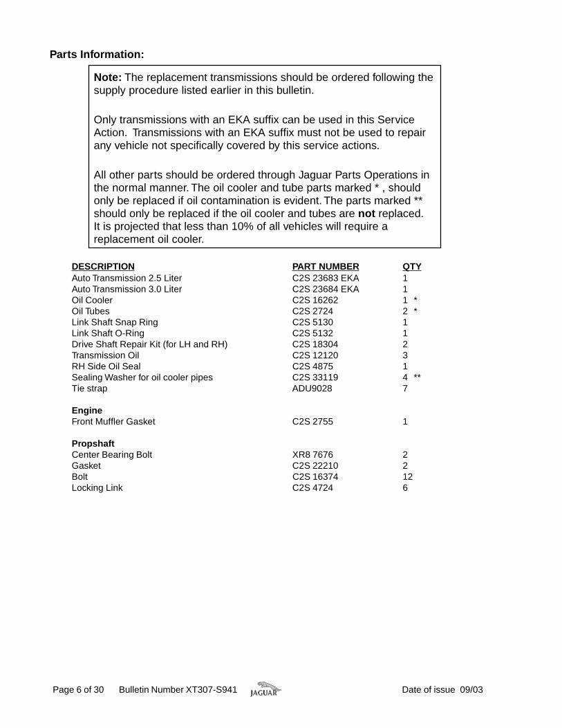
Parts Information:
Note: The replacement transmissions should be ordered following thesupply procedure listed earlier in this bulletin.
Only transmissions with an EKA suffix can be used in this ServiceAction. Transmissions with an EKA suffix must not be used to repairany vehicle not specifically covered by this service actions.
All other parts should be ordered through Jaguar Parts Operations inthe normal manner. The oil cooler and tube parts marked * , shouldonly be replaced if oil contamination is evident. The parts marked **should only be replaced if the oil cooler and tubes are not replaced.It is projected that less than 10% of all vehicles will require areplacement oil cooler.
DESCRIPTION PART NUMBER QTYAuto Transmission 2.5 Liter C2S 23683 EKA 1Auto Transmission 3.0 Liter C2S 23684 EKA 1Oil Cooler C2S 16262 1 *Oil Tubes C2S 2724 2 *Link Shaft Snap Ring C2S 5130 1Link Shaft O-Ring C2S 5132 1Drive Shaft Repair Kit (for LH and RH) C2S 18304 2Transmission Oil C2S 12120 3RH Side Oil Seal C2S 4875 1Sealing Washer for oil cooler pipes C2S 33119 4 **Tie strap ADU9028 7
EngineFront Muffler Gasket C2S 2755 1
PropshaftCenter Bearing Bolt XR8 7676 2Gasket C2S 22210 2Bolt C2S 16374 12Locking Link C2S 4724 6

Date of issue 09/03 Bulletin Number XT307-S941 Page 7 of 30
• The return of the replaced transmission will be handled outside of normal WarrantyReturn Procedures. No warranty bar code tags will be issued requesting the partbe returned to Paramus, NJ.
• Do not ship these transmissions with other warranty material.
• No core charges have been applied to the transmissions involved in this ServiceAction.
• Failure to return the transmissions in a timely manner may result in delay in thesupply of further transmission replacement units under this Service Action.
• The removed part return procedures of this Service Action must be adhered to asotherwise debit action may be taken against the Dealership.
Warranty Information:The mobility allowance is a contribution towards the costs associated with supportingcustomers’ mobility requirements while this repair is being performed and may beclaimed where the repairing dealer has provided some form of mobility assistance suchas taxi fares. It can also be used to contribute towards any loaner car costs should aloaner car be used for this purpose. Evidence of the cost claimed should be retainedwith the repair order in line with current Warranty Policy and Procedures. The sundryvalue should be entered in local currency and must not exceed the equivalent value of$40.00 US.Jaguar Cars will be providing a further allowance of $50.00 US per repair as anincentive to return the removed transmission in a timely manner as well as to cover theadministration of this Service Action.The sundry value should be entered in localcurrency and must not exceed the equivalent value of $50.00 US. This incentive will notbe paid in the event of a failure to comply with the Return Guidelines.Warranty claims should be submitted quoting program code S941 together with optioncode X. In this instance it will also be necessary for you to enter the relevant SROs fromthe table below, the parts required for the repair and where required, the relevant sundryallowances in local currency for the mobility and administration allowances.
Page 8 of 30 Bulletin Number XT307-S941 Date of issue 09/03
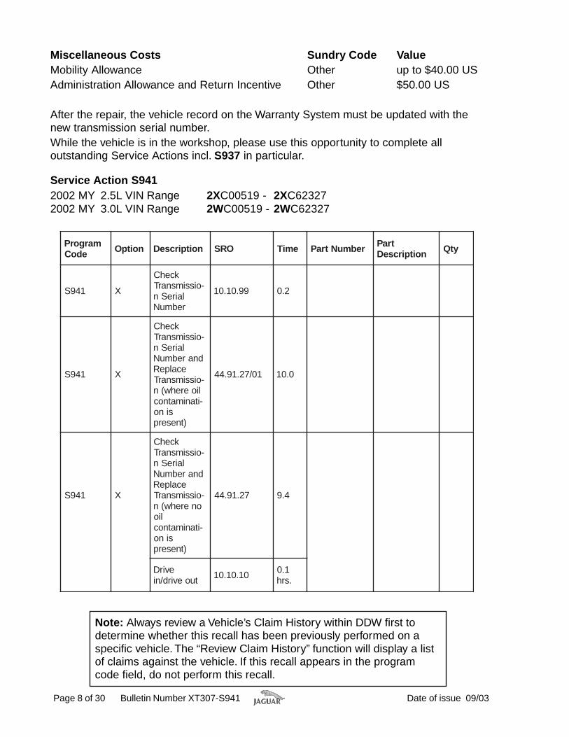
Service Action S9412002 MY 2.5L VIN Range 2XC00519 - 2XC623272002 MY 3.0L VIN Range 2WC00519 - 2WC62327
margorPedoC noitpO noitpircseD ORS emiT rebmuNtraP traP
noitpircseD ytQ
149S X
kcehC-oissimsnarT
laireSnrebmuN
99.01.01 2.0
149S X
kcehC-oissimsnarT
laireSndnarebmuN
ecalpeR-oissimsnarT
lioerehw(n-itanimatnoc
sino)tneserp
10/72.19.44 0.01
149S X
kcehC-oissimsnarT
laireSndnarebmuN
ecalpeR-oissimsnarT
onerehw(nlio
-itanimatnocsino
)tneserp
72.19.44 4.9
evirDtuoevird/ni 01.01.01 1.0
.srh
Note: Always review a Vehicle’s Claim History within DDW first todetermine whether this recall has been previously performed on aspecific vehicle. The “Review Claim History” function will display a listof claims against the vehicle. If this recall appears in the programcode field, do not perform this recall.
Miscellaneous Costs Sundry Code ValueMobility Allowance Other up to $40.00 USAdministration Allowance and Return Incentive Other $50.00 US
After the repair, the vehicle record on the Warranty System must be updated with thenew transmission serial number.While the vehicle is in the workshop, please use this opportunity to complete alloutstanding Service Actions incl. S937 in particular.

Date of issue 09/03 z Bulletin Number XT307-S941 Page 9 of 30
Transmission Serial Number Check Procedure 1. Open hood and place covers over fenders. 2. Check the transmission serial number to verify the status of the transmission. 3. The transmission serial number is located on the
top of the transmission and can be viewed when looking down between the brake reservoir and the battery cover (arrow, Illustration 1) If the transmission serial number starts with 11*****, 12***** or 13***** on 2.5L and 3.0L vehicles, or is between 1908384 to 1X09438 on 3.0L vehicles, or 1908190 to 1X08740 on 2.5L vehicles, the transmission MUST be replaced unless the serial number has a suffix 'A' or 'R' stamped behind the number.
Note: For transmission replacement, refer to procedure on next page.
Illustration 1 4. If it is not necessary to install a new transmission, remove fender protectors, close hood.

Date of issue 09/03 z Bulletin Number XT307-S941 Page 10 of 30
Transmission Replacement Procedure
Note: This is a different Workshop Procedure than the one currently described in JTIS 19.
1. Disconnect battery and remove battery tray (see Workshop Manual, JTIS CD ROM section: 414-01, SRO 86.15.11).
2. Remove air cleaner (see Workshop Manual, JTIS CD ROM section: 303-12, SRO 19.10.05). 3. Loosen, but do not remove, strut top securing
nuts on both sides (Illustration 1).
Illustration 1 4. Raise vehicle on two-post ramp. 5. Remove front wheels (see Workshop Manual, JTIS CD ROM section: 204-04, SRO 70.20.05). 6. Remove right hand fender liner access cover
(Illustration 2).
Illustration 2 7. Remove undertray (see Workshop Manual, JTIS CD ROM section: 501-02, SRO 76.22.90). 8. Remove drive shaft (see Workshop Manual, JTIS CD ROM section: 205-01, SRO 47.15.01). 9. Remove intermediate pipe, front muffler and muffler intake pipe (see Workshop Manual, JTIS CD ROM
section: 309-00, SRO 30.10.18 and 30.10.06). 10. Remove front subframe (see Workshop Manual, JTIS CD ROM section: 502-00, SRO 60.35.05).
Date of issue 09/03 z Bulletin Number XT307-S941 Page 11 of 30
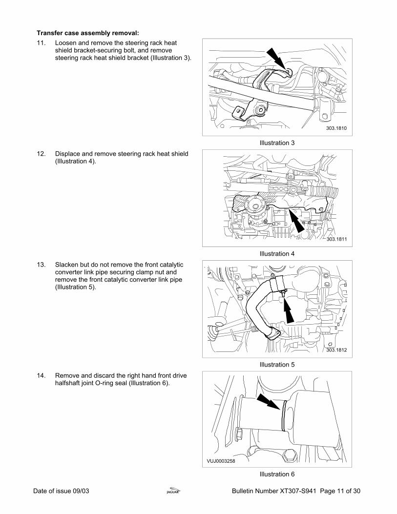
Transfer case assembly removal: 11. Loosen and remove the steering rack heat
shield bracket-securing bolt, and remove steering rack heat shield bracket (Illustration 3).
Illustration 3 12. Displace and remove steering rack heat shield
(Illustration 4).
Illustration 4 13. Slacken but do not remove the front catalytic
converter link pipe securing clamp nut and remove the front catalytic converter link pipe (Illustration 5).
Illustration 5 14. Remove and discard the right hand front drive
halfshaft joint O-ring seal (Illustration 6).
Illustration 6

Date of issue 09/03 z Bulletin Number XT307-S941 Page 12 of 30
15. Using special tools 307-443 and 307-442
displace and remove front drive halfshaft from transfer case link shaft (Illustration 7).
Illustration 7 16. Using a suitable tie strap secure the front drive
halfshaft to the body (Illustration 8).
Illustration 8 17. Remove and discard the front drive halfshaft
snap-ring (Illustration 9).
Illustration 9 18. Loosen and remove the transfer case lower
support bracket securing bolts and remove bracket from the vehicle (Illustration 10).
Illustration 10

Date of issue 09/03 z Bulletin Number XT307-S941 Page 13 of 30
19. Loosen and remove the catalytic converter to
catalytic converter mounting bracket securing bolts (Illustration 11).
Illustration 11 20. Slacken but do not remove the catalytic
converter mounting bracket top left hand bolt using special tool number 303-1069 and suitable extension (Illustration 12).
Illustration 12 21. Loosen and remove the remaining catalytic
converter mounting bracket securing bolts (Illustration 13).
Illustration 13 22. Loosen and remove the transfer case support
bracket securing bolts (Illustration 14).
Illustration 14

Date of issue 09/03 z Bulletin Number XT307-S941 Page 14 of 30
23. Loosen and remove the transfer case support
bracket securing nuts (Illustration 15).
Illustration 15 24. Loosen and remove the transfer case support
bracket upper securing bolt (Illustration 16).
Illustration 16 25. Displace and remove the catalytic converter mounting bracket. 26. Displace and remove the transfer case support bracket.
CAUTION: THE TRANSFER CASE LINK SHAFT SHOULD ONLY BE EXTRACTED BY A MAXIMUM OF 200 MILLIMETER OR DAMAGE WILL OCCUR TO THE INTERNAL SEAL.
27. Using special tools 100-012 and 100-012-03 displace transfer case link shaft (Illustration 17).
Illustration 17 28. Loosen and remove special tool 100-012 and 100-012-03 from the link shaft.

Date of issue 09/03 z Bulletin Number XT307-S941 Page 15 of 30
29. Align and install special tool 307-446 and install
and fully tighten securing bolt to the transfer case and extract link shaft to special tool (Illustration 18).
Illustration 18 30. Position the powertrain assembly jack under the vehicle. 31. Align and install the powertrain assembly jack
adaptor to the transfer case rear stud and tighten securing nut. Position the powertrain assembly jack and support blocks and adjust the support to the adaptor (Illustration 19).
Illustration 19 32. Loosen and remove the transfer case securing
bolts (Illustration 20).
Illustration 20 33. Displace the transfer case from the transmission and remove the transfer case by lowering the
powertrain assembly jack. 34. With an assistant remove the transfer case from the powertrain assembly jack and place on a bench. 35. Reposition the link shaft into the transfer case.

Date of issue 09/03 z Bulletin Number XT307-S941 Page 16 of 30
36. Remove and discard the transfer case O-ring
seal (Illustration 21).
Illustration 21 37. Remove and discard the link shaft snap-ring
(Illustration 22).
Illustration 22 38. Loosen and remove special tool 307-446 securing bolt, remove special tool and extract the link shaft
from the transfer case. 39. Using special tool 308-208 remove the link shaft
oil seal (Illustration 23).
Illustration 23 40. Install suitable blanking covers to the transfer case apertures. 41. Cover the transmission to transfer case shaft with suitable lint free, clean cloth. Transmission assembly removal and installation: 42. Place a suitable container under the transmission drain plug and drain the transmission.
Note: When draining transmission fluid, check for contamination or metallic particles. If an internal problem is suspected because the fluid is burnt or discolored, drain the transmission fluid through a paper filter. A small amount of metal or friction particles may be found from normal wear. However, if excessive metal and friction particles are present, the transmission oil cooler & tubes must be replaced.
Install the transmission drain plug. Tighten to 45 Nm.
Date of issue 09/03 z Bulletin Number XT307-S941 Page 17 of 30
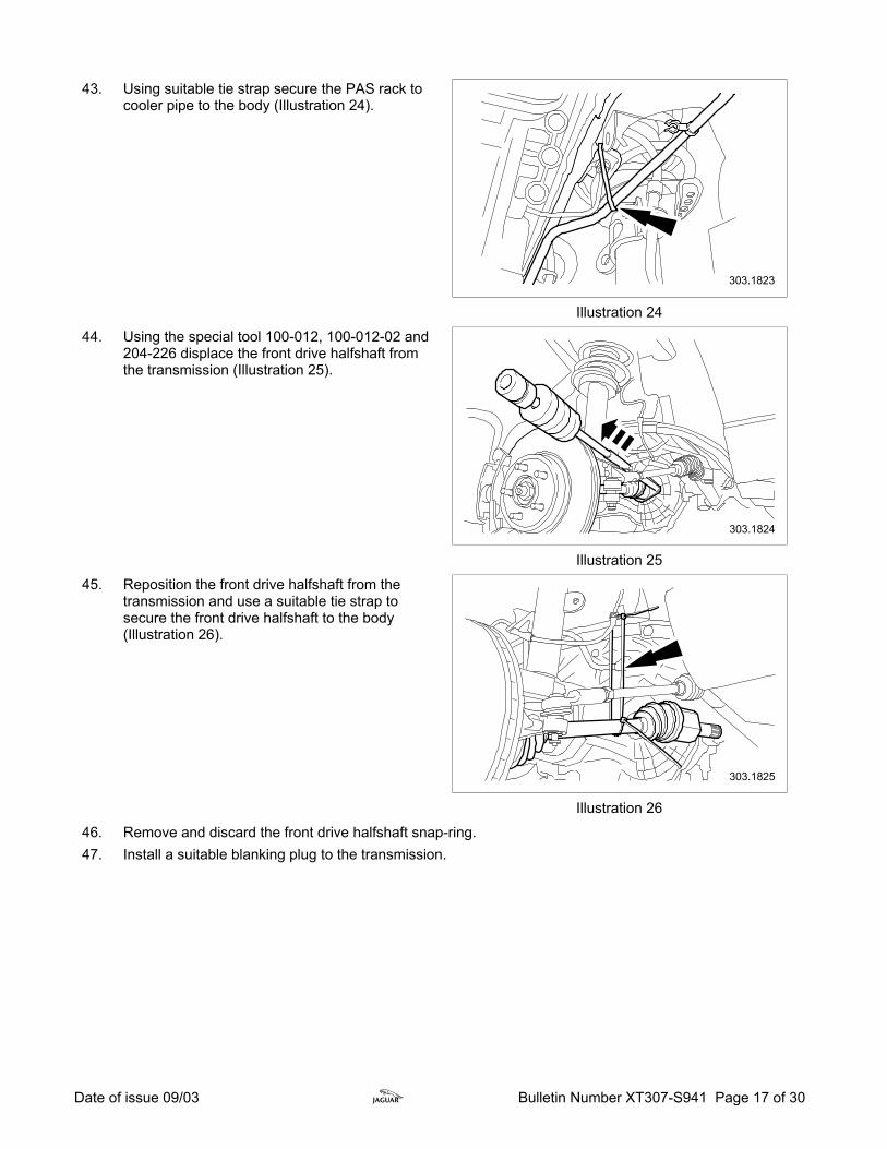
43. Using suitable tie strap secure the PAS rack to
cooler pipe to the body (Illustration 24).
Illustration 24 44. Using the special tool 100-012, 100-012-02 and
204-226 displace the front drive halfshaft from the transmission (Illustration 25).
Illustration 25 45. Reposition the front drive halfshaft from the
transmission and use a suitable tie strap to secure the front drive halfshaft to the body (Illustration 26).
Illustration 26 46. Remove and discard the front drive halfshaft snap-ring. 47. Install a suitable blanking plug to the transmission.
Date of issue 09/03 z Bulletin Number XT307-S941 Page 18 of 30
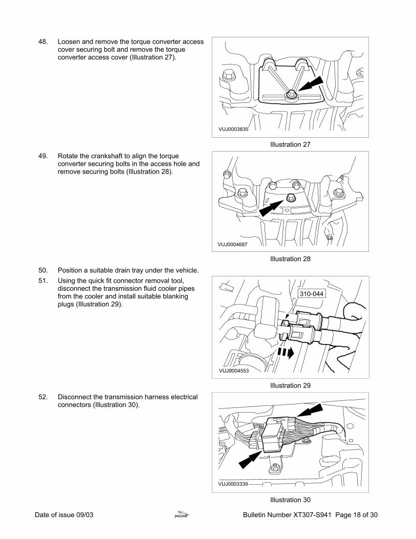
48. Loosen and remove the torque converter access
cover securing bolt and remove the torque converter access cover (Illustration 27).
Illustration 27 49. Rotate the crankshaft to align the torque
converter securing bolts in the access hole and remove securing bolts (Illustration 28).
Illustration 28 50. Position a suitable drain tray under the vehicle. 51. Using the quick fit connector removal tool,
disconnect the transmission fluid cooler pipes from the cooler and install suitable blanking plugs (Illustration 29).
Illustration 29 52. Disconnect the transmission harness electrical
connectors (Illustration 30).
Illustration 30

Date of issue 09/03 z Bulletin Number XT307-S941 Page 19 of 30
53. Lower vehicle on ramp. 54. Displace and reposition the generator harness
from the cam cover mounting stud (Illustration 31).
Illustration 31 55. Loosen and remove the top hose to air cleaner
mounting bracket securing bolt and air cleaner mounting bracket to cam cover securing nuts (Illustration 32).
Illustration 32 56. Displace and reposition the air cleaner mounting bracket from the cam cover mounting studs. 57. Align the front engine support bracket, special
tool number 303-1068, to the front of the engine and fully tighten securing bolt (Illustration 33).
Illustration 33

Date of issue 09/03 z Bulletin Number XT307-S941 Page 20 of 30
58. Displace and reposition the fuel injection
harness electrical connector from the intake manifold support bracket (Illustration 34).
Illustration 34 59. Loosen and remove the intake manifold support
bracket securing bolts and remove bracket from vehicle (Illustration 35).
Illustration 35 60. Displace the positive crankcase ventilation
(PCV) hose from the intake manifold (Illustration 36).
Illustration 36 61. Loosen and remove the engine harness
mounting bracket securing nut and displace bracket from stud (Illustration 37).
Illustration 37

Date of issue 09/03 z Bulletin Number XT307-S941 Page 21 of 30
62. Install and align the rear engine support bracket
special tool number 303-1068 to the rear of the engine and install and fully tighten the securing bolts into the rear of the cylinder head (Illustration 38).
Illustration 38 63. Align and install the engine support beam
special tool number 303-021 and 303-662 to the vehicle and support the engine from the support brackets (Illustration 39).
Illustration 39 64. Loosen and remove the transmission mounting
brace bar bolts and the transmission mounting retaining nut and displace and remove brace bar (Illustration 40).
Illustration 40 65. Install and fully tighten the transmission
mounting retaining nut (Illustration 41).
Illustration 41
Date of issue 09/03 z Bulletin Number XT307-S941 Page 22 of 30
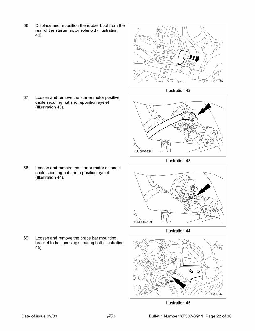
66. Displace and reposition the rubber boot from the
rear of the starter motor solenoid (Illustration 42).
Illustration 42 67. Loosen and remove the starter motor positive
cable securing nut and reposition eyelet (Illustration 43).
Illustration 43 68. Loosen and remove the starter motor solenoid
cable securing nut and reposition eyelet (Illustration 44).
Illustration 44 69. Loosen and remove the brace bar mounting
bracket to bell housing securing bolt (Illustration 45).
Illustration 45

Date of issue 09/03 z Bulletin Number XT307-S941 Page 23 of 30
70. Loosen and remove the brace bar mounting
bracket to starter motor securing bolt and remove bracket from vehicle (Illustration 46).
Illustration 46 71. Loosen and remove the starter motor securing
bolt (Illustration 47).
Illustration 47 72. Displace and remove the starter motor. 73. Loosen and remove the transmission ground
strap securing bolt (Illustration 48).
Illustration 48 74. Loosen and remove the top two bell housing bolts.

Date of issue 09/03 z Bulletin Number XT307-S941 Page 24 of 30
75. Loosen and remove the transmission mounting
to transmission securing bolts (Illustration 49).
Illustration 49 76. Raise vehicle on ramp. 77. Loosen and remove the front bell housing nut
and upper bolt and leave the lower bolt captive to the block (Illustration 50).
Illustration 50 78. Loosen and remove the lower two bell housing
bolts (Illustration 51).
Illustration 51 79. Position the powertrain assembly jack under the vehicle.
Date of issue 09/03 z Bulletin Number XT307-S941 Page 25 of 30
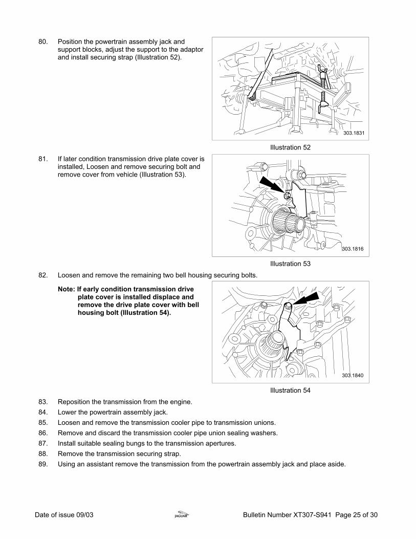
80. Position the powertrain assembly jack and
support blocks, adjust the support to the adaptor and install securing strap (Illustration 52).
Illustration 52 81. If later condition transmission drive plate cover is
installed, Loosen and remove securing bolt and remove cover from vehicle (Illustration 53).
Illustration 53 82. Loosen and remove the remaining two bell housing securing bolts. Note: If early condition transmission drive
plate cover is installed displace and remove the drive plate cover with bell housing bolt (Illustration 54).
Illustration 54 83. Reposition the transmission from the engine. 84. Lower the powertrain assembly jack. 85. Loosen and remove the transmission cooler pipe to transmission unions. 86. Remove and discard the transmission cooler pipe union sealing washers. 87. Install suitable sealing bungs to the transmission apertures. 88. Remove the transmission securing strap. 89. Using an assistant remove the transmission from the powertrain assembly jack and place aside.
Date of issue 09/03 z Bulletin Number XT307-S941 Page 26 of 30
PAS Cooler flush or replace procedure
Note: If no contamination or metallic particles were identified at step 42 use a suitable syringe to flush the cooler and cooler pipes with new fluid then continue with the transmission installation procedure, if contamination or metallic particles were identified follow the steps below
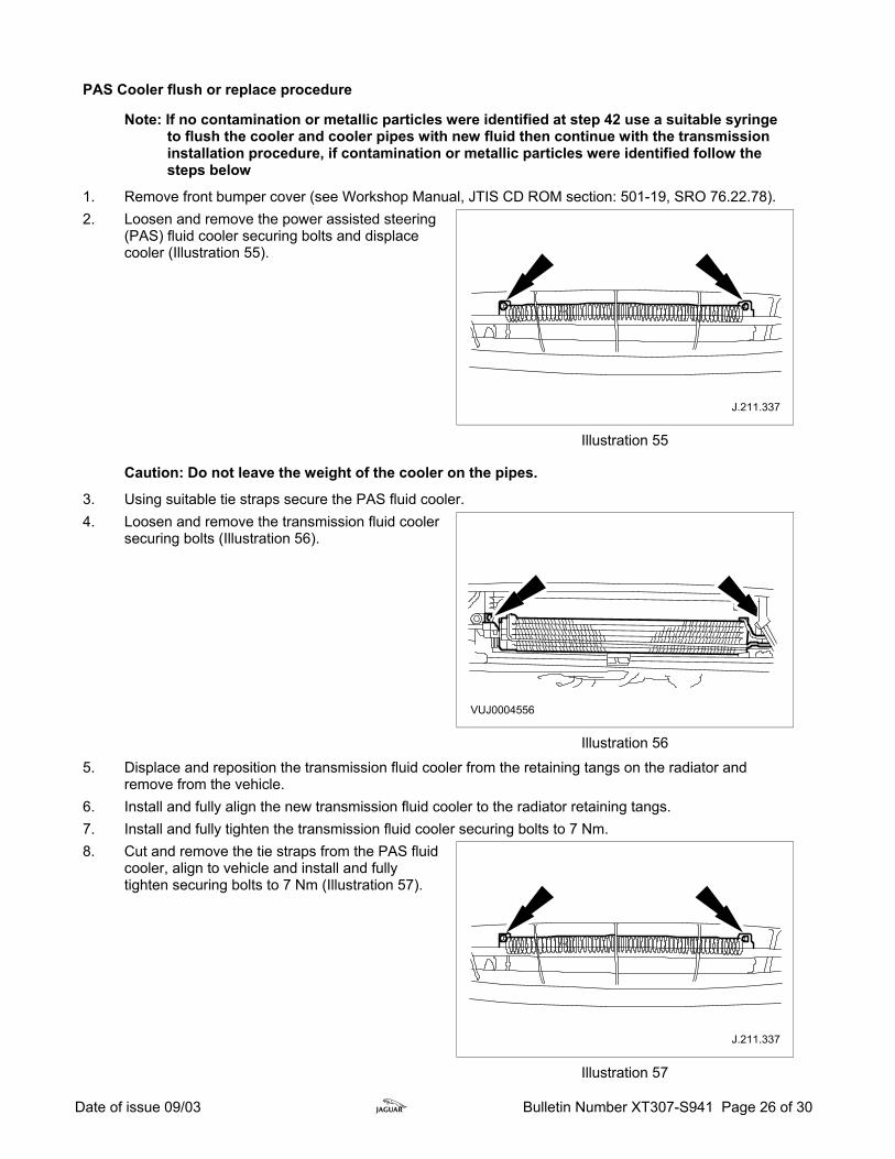
1. Remove front bumper cover (see Workshop Manual, JTIS CD ROM section: 501-19, SRO 76.22.78). 2. Loosen and remove the power assisted steering
(PAS) fluid cooler securing bolts and displace cooler (Illustration 55).
Illustration 55
Caution: Do not leave the weight of the cooler on the pipes.
3. Using suitable tie straps secure the PAS fluid cooler. 4. Loosen and remove the transmission fluid cooler
securing bolts (Illustration 56).
Illustration 56 5. Displace and reposition the transmission fluid cooler from the retaining tangs on the radiator and
remove from the vehicle. 6. Install and fully align the new transmission fluid cooler to the radiator retaining tangs. 7. Install and fully tighten the transmission fluid cooler securing bolts to 7 Nm. 8. Cut and remove the tie straps from the PAS fluid
cooler, align to vehicle and install and fully tighten securing bolts to 7 Nm (Illustration 57).
Illustration 57
Date of issue 09/03 z Bulletin Number XT307-S941 Page 27 of 30
9. Install front bumper cover (see Workshop Manual, JTIS CD ROM section: 501-19, SRO 76.22.78). Transmission Installation Procedure Check the condition of the new transmission and torque converter for any damage. 1. Using an assistant place the new transmission to the powertrain assembly jack. 2. Install a securing strap around the new transmission.
3. Install the transmission cooler pipes to the transmission and fully tighten unions to 35 Nm.
Note: If no contamination or metallic particles were identified at step 42 of the removal procedure, install new sealing washers to unions and re-install existing cooler pipes. If contamination or metallic particles were identified, install new cooler pipes.
4. Displace and remove all of the transmission aperture sealing bungs. 5. Position the transmission to the engine. 6. Install and fully tighten the two bell housing bolts fitted to the doweled holes to 48 Nm.
Note: If an early-style transmission is to be installed in a vehicle that came with the later-style transmission, install the drive plate cover supplied with the replacement transmission.
7. If later condition transmission drive plate cover is installed, install the drive plate cover to the engine. 8. Install and fully tighten the bell housing nut to captive bolt to 48 Nm. 9. Remove the strap securing the transmission. 10. Lower and remove the powertrain assembly jack. 11. Install and fully tighten the two lower bell housing bolts to 48 Nm. 12. Lower the vehicle on the ramp. 13. Align the transmission to the transmission mounting. 14. Install and fully tighten the transmission mounting to gearbox securing bolts to 80 Nm. 15. Install and fully seat the top two bell housing bolts to 48 Nm. 16. Install and fully tighten the transmission ground cable securing bolt to 25 Nm. 17. Install the starter motor. 18. Install and fully tighten the rear starter motor securing bolt to 35 Nm. 19. Install the brace bar mounting bracket. 20. Install and fully tighten the brace bar bracket to starter motor securing bolt to 35 Nm. 21. Install and fully tighten the brace bar bracket to bell housing securing bolt to 48 Nm. 22. Reposition the starter motor solenoid cable eyelet, install and fully tighten securing nut to 6 Nm. 23. Reposition the starter motor positive cable eyelet, install and fully tighten securing nut to 12 Nm. 24. Fully seat the rubber boot to the rear of the starter motor solenoid. 25. Loosen and remove the brace bar to transmission mounting securing nut. 26. Install the transmission mounting brace bar. 27. Install and fully tighten the transmission mounting brace bar securing bolts to 25 Nm. 28. Install and fully tighten the transmission mounting brace bar securing nut to 133 Nm. 29. Remove the engine support beam from the vehicle. 30. Loosen and remove the rear engine support bracket securing bolts and remove support bracket from
engine. 31. Position and install the engine harness mounting bracket to stud, install and fully tighten securing nut to
6Nm. 32. Install PCV hose to intake manifold. 33. Position intake manifold support bracket to vehicle, install and fully tighten securing bolts to 10 Nm. 34. Position and install the fuel injection harness electrical connector to intake manifold support bracket. 35. Loosen the front engine support bracket securing bolt and remove support bracket from engine.
Date of issue 09/03 z Bulletin Number XT307-S941 Page 28 of 30
36. Position the air cleaner support bracket to cam cover studs and install and fully tighten securing nuts to
6 Nm. 37. Install and fully tighten the top hose to air cleaner mounting bracket securing bolt to 6 Nm. 38. Position and install generator harness to cam cover mounting stud. 39. Raise vehicle on ramp. 40. Connect the transmission harness electrical connectors. 41. Remove the blanking plugs from the transmission fluid cooler and cooler pipes. 42. Install and fully seat the cooler pipes. 43. Clean any residual fluid from cooler pipes. 43. Remove the drain tray. 44. Align the torque converter to the drive plate. 45. Install but do not fully tighten torque converter securing bolts, turning crankshaft to gain access to each
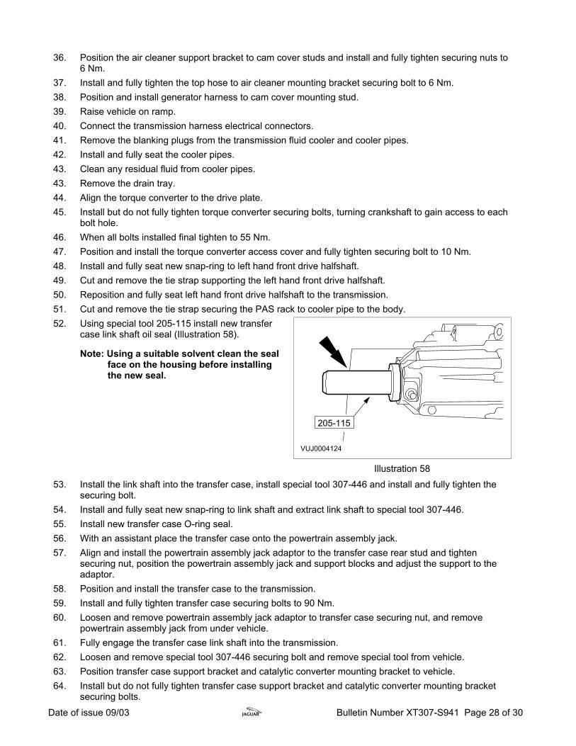
bolt hole. 46. When all bolts installed final tighten to 55 Nm. 47. Position and install the torque converter access cover and fully tighten securing bolt to 10 Nm. 48. Install and fully seat new snap-ring to left hand front drive halfshaft. 49. Cut and remove the tie strap supporting the left hand front drive halfshaft. 50. Reposition and fully seat left hand front drive halfshaft to the transmission. 51. Cut and remove the tie strap securing the PAS rack to cooler pipe to the body. 52. Using special tool 205-115 install new transfer
case link shaft oil seal (Illustration 58).
Note: Using a suitable solvent clean the seal face on the housing before installing the new seal.
Illustration 58 53. Install the link shaft into the transfer case, install special tool 307-446 and install and fully tighten the
securing bolt. 54. Install and fully seat new snap-ring to link shaft and extract link shaft to special tool 307-446. 55. Install new transfer case O-ring seal. 56. With an assistant place the transfer case onto the powertrain assembly jack. 57. Align and install the powertrain assembly jack adaptor to the transfer case rear stud and tighten
securing nut, position the powertrain assembly jack and support blocks and adjust the support to the adaptor.
58. Position and install the transfer case to the transmission. 59. Install and fully tighten transfer case securing bolts to 90 Nm. 60. Loosen and remove powertrain assembly jack adaptor to transfer case securing nut, and remove
powertrain assembly jack from under vehicle. 61. Fully engage the transfer case link shaft into the transmission. 62. Loosen and remove special tool 307-446 securing bolt and remove special tool from vehicle. 63. Position transfer case support bracket and catalytic converter mounting bracket to vehicle. 64. Install but do not fully tighten transfer case support bracket and catalytic converter mounting bracket
securing bolts.

Date of issue 09/03 z Bulletin Number XT307-S941 Page 29 of 30
65. Fully tighten catalytic converter mounting bracket to engine securing bolts to 55 Nm (using special tool
303-1069 for catalytic converter mounting bracket top left hand bolt), and catalytic converter mounting bracket to transfer case securing bolt to 25 Nm.
66. Fully tighten the transfer case support bracket upper securing bolt to 55 Nm, and transfer case support bracket to transfer case securing nuts and bolts to 35 Nm.
67. Install and fully tighten catalytic converter to catalytic converter mounting bracket securing bolts to 25 Nm.
68. Position transfer case lower support bracket to vehicle, install and fully tighten transfer case lower support bracket to engine sump securing bolt to 47 Nm, and transfer case lower support bracket to transfer case securing bolts to 25 Nm.
69. Install and fully seat a new snap-ring to right hand front drive halfshaft. 70. Place new right hand front drive halfshaft to link shaft O-ring seal to front drive halfshaft. 71. Cut and remove tie strap supporting the right hand front drive halfshaft. 72. Reposition and fully seat right hand front drive halfshaft to the transfer case link shaft. 73. Position and fully install the O-ring seal on the joint between the front drive halfshaft and the link shaft. 74. Position front catalytic converter link pipe to vehicle and fully tighten link pipe securing nut to 55 Nm. 75. Position steering rack heat shield to vehicle. 76. Position steering rack heat shield mounting bracket to heat shield and install and fully tighten securing
bolt to 4 Nm. 77. Install front sub frame (see Workshop Manual, JTIS CD ROM section: 502-00, SRO 60.35.05). 78. Install intermediate pipe, front muffler and muffler intake pipe (see Workshop Manual, JTIS CD ROM
section: 309-00, SRO 30.10.18, and 30.10.06). 79. Install drive shaft (see Workshop Manual, JTIS CD ROM section: 205-01, SRO 47.15.01). 80. Install undertray (see Workshop Manual, JTIS CD ROM section: 501-02, SRO 76.22.90). 81. Install right hand wheel arch liner access cover. 82. Install front wheels (see Workshop Manual, JTIS CD ROM section: 204-04, SRO 70.20.05). 83. Lower the ramp 84. Fully tighten the strut top securing nuts both sides to 30 Nm. 85. Install air cleaner (see Workshop Manual, JTIS CD ROM section: 303-12, SRO 19.10.05). 86. Install battery tray (see Workshop Manual, JTIS CD ROM section: 414-01, SRO 86.15.11). 87. Connect battery. 88. Position Worldwide Diagnostic System (WDS) alongside vehicle, switch Portable Test Unit (PTU) 'ON'
and allow software to load.
Note: Ensure WDS is loaded with software release JTP 759/24 or later.
89. Connect PTU to vehicle using diagnostic cable. 90. Enter VIN and navigate to configuration main menu. 91. Select 'Special Applications' then 'Transmission Control Module Adaptation Clear'.
Use this opportunity to perform Service Action S937 if this has not been done previously (Refer to Technical Bulletin XT303-S937).
92. After 'Transmission Control Module Adaptation Clear' application is complete, carry out transmission fluid level check.
Note: All transmissions are partially filled with oil, therefore the fluid level must checked and fluid added.
93. Make sure the J-Gate shift selector is in the Park position (P). With the engine running and the foot brake applied, move the J-Gate shift selector through 'P-R-N-D-4-3-2' ranges and back to the 'P' position to circulate the automatic transmission fluid until the temperature reaches 30 to 40°C (86 to 104°F) on the WDS.
Date of issue 09/03 z Bulletin Number XT307-S941 Page 30 of 30
94. When the automatic transmission fluid temperature reaches 35°C (95°F) check that the selector lever
is in the 'P' position and raise the vehicle. 95. With the engine running, remove the automatic transmission fluid level tube plug. Remove and discard
the level plug and sealing washer. Note: Use automatic transmission fluid part no. C2S 12120, this is the only fluid which meets Jaguar
specification for use in the X-TYPE 96. If the automatic transmission fluid does not come out of the transmission fluid level tube the automatic
transmission fluid level is insufficient. If this is the case add the automatic transmission fluid in 0.5 liter units into the automatic transmission fluid charging pipe until the automatic transmission fluid comes out of the automatic transmission fluid level tube.
97. Remove the automatic transmission fluid charging pipe cap Note: Make sure the automatic transmission fluid temperature does not exceed 40°C (104°F). If the
automatic transmission fluid temperature does exceed 40°C (104°F) stop the automatic transmission fluid level check procedure. Allow the automatic transmission fluid to cool until the temperature reaches 30 to 40°C (86 to 104°F).
98. If necessary, allow the automatic transmission fluid to come out of the automatic transmission fluid level tube until the overflow stops at a temperature of no more than 40°C (104°F)
99. Install a new transmission fluid level plug and sealing washer. Tighten to 15 Nm.
100. Install the automatic transmission fluid charging pipe cap. 101. After fluid level check is complete, carry out steering angle sensor calibration (if installed) then switch
'OFF' the PTU, disconnect from vehicle and return WDS to original location. 102. Check/re-set gear selector cable adjustment using workshop procedure outlined in Technical Bulletin
XT307-01.
Note: Do NOT carry out the DTC check referred to under the Action in Technical Bulletin XT307-01.
Note: The time for checking/re-setting the gear selector cable is included in this Service Action there will be no need to claim the SRO quoted in the Technical Bulletin.
103. Set the transmission mode switch to Normal. To allow the new transmission to adapt to the customer's driving requirements, the vehicle will have to be driven for approximately 300 miles (482 kilometers) without using the sport mode switch.
104. Remove fender protectors and close hood.

TRANSMISSION REPAIR PROCESSFOR VEHICLES AFFECTED BY SERVICE ACTION S941
FIRST ESTABLISH WHETHER THE VEHICLE HAS ALREADY RECEIVED A REPLACEMENT TRANSMISSION, THIS CANBE ACHIEVED BY A SIMPLE CHECK OF THE TRANSMISSION SERIAL #. THIS WILL ENSURE THAT THE
TRANSMISSION DOES NOT NEED TO BE REPLACED AGAIN
IF THE TRANSMISSION SERIAL NUMBER IS WITHIN THE RANGE OF THE SERVICE ACTION. THEN THETRANSMISSION SHOULD BE REPLACED UNLESS A LETTER IS STAMPED BEHIND THE SERIAL NUMBER SUCH AS
"A" "R" "K" "S" "U" "E" "V". IF SO, THIS WOULD INDICATE THAT THE TRANSMISSION HAS ALREADY BEENREMANUFACTURED TO THE LATEST SPECIFICATION. IN THIS CASE NO FURTHER ACTION IS NECESSARY
IS THE TRANSMISSION SERIALNUMBER IN THE RANGE PRINTED IN
THE SERVICE ACTION
END
ONCE THE TRANSMISSION IS REPLACED CLEAR THE TCM ADAPTATIONS USING WDS, IN ADDITION THETRANSMISSION OIL WILL NEED TO BE SET TO THE CORRECT LEVEL, NOTE: THE TRANSMISSIONS ARE ONLY
PARTIALLY FILLED WHEN YOU RECEIVE THEM.
ALSO PERFORM SERVICE ACTION S937 TCM / ECM REFLASH IF IT HAS NOT ALREADY BEEN COMPLETED ASTHIS IS CRITICAL TO ENSURING OPTIMUM TRANSMISSION PERFORMANCE AND DURABILITY.
TO ALLOW THE NEW TRANSMISSION TO ADAPT TO THE CUSTOMER'S DRIVING REQUIREMENTS, THE VEHICLEWILL HAVE TO BE DRIVEN FOR 300 MILES (482 KILOMETERS) WITHOUT USING THE SPORT MODE SWITCH.
NO ACTION ISNECESSARY UNDER
THIS SERVICE ACTION
Yes
No
END
START
COMPLETE THE TRANSMISSION REPLACEMENT FORM AND ENCLOSE IT WITH THE DISPLACED PART,PROTECTING IT FROM ANY OIL
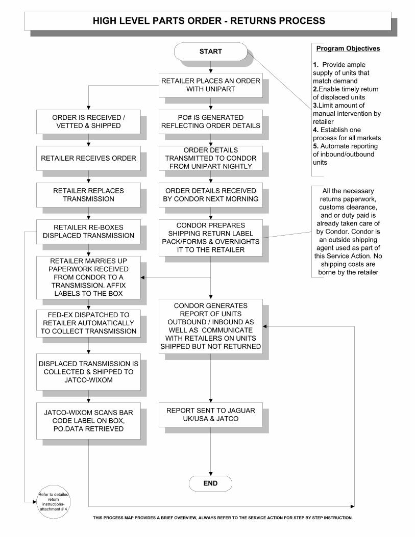
RETAILER PLACES AN ORDERWITH UNIPART
PO# IS GENERATEDREFLECTING ORDER DETAILS
ORDER IS RECEIVED /VETTED & SHIPPED
RETAILER RECEIVES ORDER
RETAILER REPLACESTRANSMISSION
RETAILER RE-BOXESDISPLACED TRANSMISSION
RETAILER MARRIES UPPAPERWORK RECEIVED
FROM CONDOR TO ATRANSMISSION. AFFIXLABELS TO THE BOX
FED-EX DISPATCHED TORETAILER AUTOMATICALLY
TO COLLECT TRANSMISSION
DISPLACED TRANSMISSION ISCOLLECTED & SHIPPED TO
JATCO-WIXOM
JATCO-WIXOM SCANS BARCODE LABEL ON BOX,PO.DATA RETRIEVED
CONDOR GENERATESREPORT OF UNITS
OUTBOUND / INBOUND ASWELL AS COMMUNICATE
WITH RETAILERS ON UNITSSHIPPED BUT NOT RETURNED
HIGH LEVEL PARTS ORDER - RETURNS PROCESS
START
END
ORDER DETAILSTRANSMITTED TO CONDOR
FROM UNIPART NIGHTLY
ORDER DETAILS RECEIVEDBY CONDOR NEXT MORNING
CONDOR PREPARESSHIPPING RETURN LABEL
PACK/FORMS & OVERNIGHTSIT TO THE RETAILER
REPORT SENT TO JAGUARUK/USA & JATCO
All the necessaryreturns paperwork,customs clearance,and or duty paid is
already taken care ofby Condor. Condor isan outside shipping
agent used as part ofthis Service Action. No
shipping costs areborne by the retailer
Program Objectives
1. Provide amplesupply of units thatmatch demand2.Enable timely returnof displaced units3.Limit amount ofmanual intervention byretailer4. Establish oneprocess for all markets5. Automate reportingof inbound/outboundunits
Refer to detailedreturn
instructions-attachment # 4
THIS PROCESS MAP PROVIDES A BRIEF OVERVIEW, ALWAYS REFER TO THE SERVICE ACTION FOR STEP BY STEP INSTRUCTION.
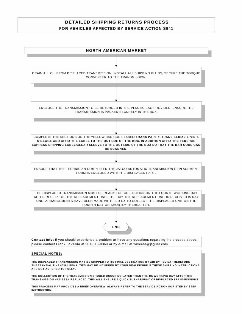
DETAILED SHIPPING RETURNS PROCESSFOR VEHICLES AFFECTED BY SERVICE ACTION S941
COMPLETE THE SECTIONS ON THE YELLOW BAR CODE LABEL: TRANS PART #, TRANS SERIAL #, VIN &MILEAGE AND AFFIX THE LABEL TO THE OUTSIDE OF THE BOX. IN ADDITION AFFIX THE FEDERAL
EXPRESS SHIPPING LABEL/CLEAR SLEEVE TO THE OUTSIDE OF THE BOX SO THAT THE BAR CODE CANBE SCANNED.
THE DISPLACED TRANSMISSION MUST BE READY FOR COLLECTION ON THE FOURTH WORKING DAYAFTER RECEIPT OF THE REPLACEMENT UNIT. THE DAY THE REPLACEMENT UNIT IS RECEIVED IS DAY
ONE. ARRANGEMENTS HAVE BEEN MADE WITH FED-EX TO COLLECT THE DISPLACED UNIT ON THEFOURTH DAY OR SHORTLY THEREAFTER.
NORTH AMERICAN MARKET
DRAIN ALL OIL FROM DISPLACED TRANSMISSION, INSTALL ALL SHIPPING PLUGS, SECURE THE TORQUECONVERTER TO THE TRANSMISSION.
ENCLOSE THE TRANSMISSION TO BE RETURNED IN THE PLASTIC BAG PROVIDED, ENSURE THETRANSMISSION IS PACKED SECURELY IN THE BOX.
SPECIAL NOTES:
THE DISPLACED TRANSMISSION MAY BE SHIPPED TO ITS FINAL DESTINATION BY AIR BY FED EX THEREFORESUBSTANTIAL FINANCIAL PENALTIES MAY BE INCURRED BY YOUR DEALERSHIP IF THESE SHIPPING INSTRUCTIONSARE NOT ADHERED TO FULLY.
THE COLLECTION OF THE TRANSMISSION SHOULD OCCUR NO LATER THAN THE 4th W ORKING DAY AFTER THETRANSMISSION HAS BEEN REPLACED. THIS W ILL ENSURE A QUICK TURNAROUND OF DISPLACED TRANSMISSIONS.
THIS PROCESS MAP PROVIDES A BRIEF OVERVIEW , ALW AYS REFER TO THE SERVICE ACTION FOR STEP BY STEPINSTRUCTION.
END
ENSURE THAT THE TECHNICIAN COMPLETED THE JATCO AUTOMATIC TRANSMISSION REPLACEMENTFORM IS ENCLOSED WITH THE DISPLACED PART.
Contact Info: If you should experience a problem or have any questions regarding the process above,please contact Frank LaVerda at 201-818-8363 or by e-mail at [email protected]

June 2003 To: Jaguar Service Managers RE: Jaguar Service Action S941 Enclosed please find the following service tools to be used on X Type vehicles during the performance of service action S941. 303-1068 Engine support brackets 303-1069 Torque adapter Details as to their proper use will be supplied with the release of Service Action S941. Please retain these tools in a suitable location within the X Type service tool cabinet JAG.059. If you have any additional questions, please contact the Jaguar Technical Hotline at 1-888-JAG-DLRS (524-3577). George Malarczuk Aston Martin Jaguar Land Rover National Service Support (201) 818-8022 (phone) (201) 818-8234 (fax) [email protected]
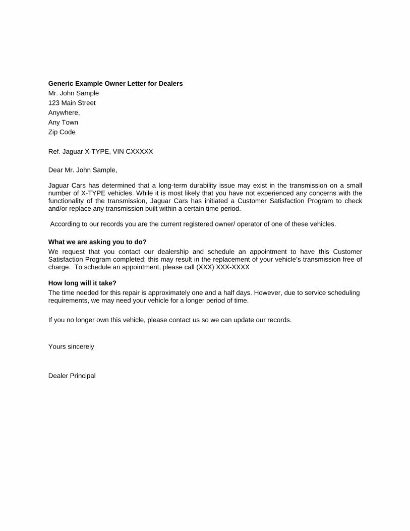
Generic Example Owner Letter for Dealers Mr. John Sample 123 Main Street Anywhere, Any Town Zip Code Ref. Jaguar X-TYPE, VIN CXXXXX Dear Mr. John Sample, Jaguar Cars has determined that a long-term durability issue may exist in the transmission on a small number of X-TYPE vehicles. While it is most likely that you have not experienced any concerns with the functionality of the transmission, Jaguar Cars has initiated a Customer Satisfaction Program to check and/or replace any transmission built within a certain time period. According to our records you are the current registered owner/ operator of one of these vehicles. What we are asking you to do? We request that you contact our dealership and schedule an appointment to have this Customer Satisfaction Program completed; this may result in the replacement of your vehicle’s transmission free of charge. To schedule an appointment, please call (XXX) XXX-XXXX How long will it take? The time needed for this repair is approximately one and a half days. However, due to service scheduling requirements, we may need your vehicle for a longer period of time. If you no longer own this vehicle, please contact us so we can update our records. Yours sincerely Dealer Principal

Instructions for entering Serialized Components on Warranty Claims The following procedures should be followed to submit a warranty claim containing a component for which Jaguar requests the new serial number be recorded. The process for submitting a warranty claim containing serialized component is the same as with any other claim. However, you will need to enter a few additional pieces of data prior to submitting the claim for payment. Please refer to the section below that applies to your dealership's systems for specific instructions. ADP Dealer Management System
1. After a Repair Order has been closed, use the Prepare Manufactures Transmission (PMT) function to select the RO/Claim you wish to modify.
2. Ensure all the Claim Header Information is correct, as you would for any claim. 1. Select the Line that contains the claim for the Serialized Component. 2. Ensure all details are correct including the Claim Type, Program Code, etc. 3. Proceed to the fourth screen, which contains the Serial Number Change and Tax Information fields. 4. Select "1" to enter the Component information. 5. Enter the component code, for example, "GB" for Gearbox. You may also view al list of all valid
codes by typing an "L" in the "Comp Code" field. 6. Entering the old component's serial number is optional. 7. Enter the new component's serial number. This information is required whenever a Component Code
has been entered. 8. Resume the normal process for submitting warranty claims.
Reynolds and Reynolds Dealer Management System
1. After the Repair Order has been closed, use the Data Exchange (3690) interface and select option "2" for Jaguar Warranty Claims.
2. Enter "R" to display a list of all Repair Orders that have been closed and are available for review. 3. Select a Claim to edit from the list by entering its line number. 4. Enter "?" in the "Claim Number" prompt to display a list of claims available for review. Select the
claim that contains the serilized component you would like to modify by entering the line number at the prompt. The claim details will be displayed.
5. Enter "M" to modify the claim. Complete or change the information on the claim header screen as necessary.
6. At the bottom of the screen, select "SN" to select the "Serialized Component" screen. 7. Enter "A" to add a part line. 8. Enter the component code, for example, "GB" for Gearbox. To view a list of valid codes, enter "?" at
the "Comp Code" prompt. Select the applicable code by entering its line number. 9. Entering the old component's serial number is optional. 10. Enter the new component's serial number. This information is required whenever a Component Code
has been entered. 11. Resume the normal process for submitting Warranty Claims.
UCS Dealer Management System There are no fields to enter serialized components within the UCS DCS interface. Any claims that require serial numbers to be entered should be submitted using DDW. Refer to the instructions in the DDW section to submit claims with Serialized Components. DDW (Direct Dealer Warranty, Manual Claim Entry) If your dealership does not have a claims download function or you are using UCS, refer to the instructions below for submitting a claim using DDW.
1. Sign into the DDW application. 2. Under the "Claim Management" section, select "Add a Claim". 3. Enter all claim information as required. 4. Scroll down to the "Add – Component Serial Numbers" section. 5. Enter the component code, for example, "GB" for Gearbox. To view a complete list of valid codes,
click on the down arrow button to the right of the "Types" list box. Select the applicable component. 6. The Description field will automatically be filled in for you. 7. Enter the new component's serial number in the "Serial Number" field. 8. Continue completing any additional required fields. 9. Resume the normal process for submitting Warranty Claims. Refer to page 5 of the G-ACES and
DDW User Guide for a more details of submitting claims using DDW. For additional assistance, please contact the Premier BAC at 800-392-9090.