Service Manual X10 - Scout Mobility
80
Service Manual X10 V1.0 from March 1st 2017
Transcript of Service Manual X10 - Scout Mobility
Service Manual
X10
V1.0 from March 1st 2017

Copyright (C) 2015 Scout Mobility BV All rights reserved. The information provided may not be reproduced and/or published in any form, or by any other means whatsoever( electronically or mechanically) without the prior written authorization of Scout Mobility BV.
The information provided is based on general data about the constructions known at the time of the publication of this manual. Scout Mobility BV strives to continuous product improvement and reserves the right to changes and modifications.
The information provided is valid for the product in its standard version. Scout Mobility BV cannot be held liable for possible damage resulting from specifications of the product deviating from the standard configuration.
The available information has been prepared with all possible care, but Scout Mobility BV cannot be held liable for possible errors in the information or the consequences thereof. Scout Mobility BV accepts no liability for loss resulting from work that is executed by third parties.
The names, trade names, etc. used by Scout Mobility BV may not, according to the legislation concerning the protection of trade names, be considered as being available.

Table of contents
Service manual - X10 3
Table of contents Copyright ............................................................................................................................... 2
Table of contents.................................................................................................................... 3
1. Introduction ........................................................................................................................ 4
1.1. Scope of this manual ................................................................................................... 4
1.2. Reference documentation ........................................................................................... 4
1.3. Symbols used in this manual ....................................................................................... 4
1.4. Guidelines and useful information for maintenance ..................................................... 5
1.5. Product identification ................................................................................................... 6
2. Warranty and Liability ......................................................................................................... 7
2.1. Warranty ..................................................................................................................... 8
2.2. Liability ........................................................................................................................ 9
3. Safety ............................................................................................................................... 10
3.1. Personnel qualifications ............................................................................................ 10
3.2. Cautions and warning statements ............................................................................. 10
3.3. Pictograms on the wheelchair ................................................................................... 12
4. Maintenance schedule & tooling ....................................................................................... 13
4.1. Overview of scheduled maintenance tasks................................................................ 13
4.2. Mechanical tools ....................................................................................................... 14
4.3. Electronical tools ....................................................................................................... 14
4.4. Torque table .............................................................................................................. 15
5. Maintenance on the control system .................................................................................. 16
5.1. Replace the remote control (Shark, VR2 and R-Net) ................................................. 16
5.2. Replace the remote control (DX2) ............................................................................. 16
5.3. Replace the power module (Shark, VR2 and R-Net) ................................................. 16
5.4. Replace the power module (DX2) ............................................................................. 16
6. Troubleshooting ............................................................................................................... 18
6.3. Diagnostics and troubleshooting for DX2 controls ..................................................... 26
6.4. Diagnostics and troubleshooting for R-Net controls ................................................... 30
6.5. Diagnostics and troubleshooting for VR2 controls ..................................................... 34
7. Cable and module schemes ............................................................................................. 37
7.1. Shark controls ........................................................................................................... 37
7.2. DX2 controls ............................................................................................................. 37
7.3. VR2 controls ............................................................................................................. 37
7.4. R-Net controls ........................................................................................................... 38
8. Version history ................................................................................................................. 41
9. Appendices ...................................................................................................................... 42 Parts ................................................................................................................................ 58

4 Service manual - X10
Introduction
1. Introduction
1.1. Scope of this manual This service manual contains information and instructions about general maintenance and repairs of this electric wheelchair. This service manual is meant for:
• Service technicians: personnel that performs the regular maintenance and that solves
technical problems to the wheelchair. Only service technicians that have completed the equipment training for this wheelchair are allowed to do maintenance on this wheelchair.
• Customer support personnel at Scout Mobility BV dealers: personnel that support customers when customers call to the dealer's office with questions about the wheelchair. For customer support this manual serves as reference material.
1.2. Reference documentation
This service manual refers, where necessary, to one of the other manuals that are available for this wheelchair. • User manual wheelchair: for general information about the use of the wheelchair. • User manual for the electronics: for detailed information about the use of the controller
of the wheelchair. • User manual for the seating system: for detailed information about the user
adjustments and the use of the seating system. • Spare parts manual: for information about the spare parts and their ordering numbers. • Supplier documentation for the electronics: for detailed information about changing
settings and doing repairs on the controls of the wheelchair. 1.3. Symbols used in this manual
This manual uses the following symbols to highlight information that needs extra attention.
WARNING! Follow the instructions next to this symbol closely. Not paying careful attention to these instructions could result in physical injury or damage to the wheelchair or to the environment.
NOTICE! This provides useful background information.

Service manual - X10 5
Introduction
1.4. Guidelines and useful information for maintenance Service technicians Maintenance (regular maintenance and repairs) to the wheelchair may only be done by service technicians that have been trained and authorized by Scout Mobility BV. Temporary employees and personnel in training are also allowed to do this work but only under the supervision of an authorized service technician.
Work safely Always make sure that you work safely, particularly when you need to lift up the wheelchair. During maintenance and repair work you are at all times fully responsible to obey the local applicable guidelines and standards with regard to safety and environment. We advise you to contact our service department before you do repairs to a wheelchair that has been involved in an accident. We advise you to disconnect the wheelchair from the battery power, if the wheelchair has to be repaired because of a fault condition. Remove the main fuse(s) while the wheelchair is unattended.
Service and technical support For information about settings, maintenance and repair works, please contact you supplier.
Make sure you have the following information at hand: • Type • Identification number • Year of manufacture
This information is printed on the identification plate of the wheelchair.
How to order spare parts When you order spare parts, please specify: • Identification number • Part number • amount of parts you need • description (in the relevant language) • dimensions (if applicable)
Please use e-mail or fax to send your orders to your supplier.
Remarks: • Parts that do not have a position number cannot be ordered separately. Such parts
belong to an assembly that must be ordered and replaced as one piece. • Boxed position numbers refer to the relevant separate drawing.
Disposal Always handle waste materials according to the local regulations.
Contact information Scout Mobility BV Scout Mobility BV Kanaalstraat 101d 5711 EG Someren The Netherlands T +31 (0)6 44 50 05 78 www.scoutmobility.nl [email protected]

6 Service manual - X10
Introduction
1.5. Product identification
A. Model B. Year of manufacture C. Identification number D. Maximum load in kg E. Maximum Safe Slope

Service manual - X10 7
Warranty and Liability
2. Warranty and Liability In the following warranty and liability stipulations the following terms are used:
• Product: the electric wheelchair manufactured Scout Mobility BV. • User: the person who actually uses the product. • Customer: the person who obtains the product from Scout Mobility BV. • Dealer: the person/company who supplies the product from Scout Mobility BV to
the customer.
8 Service manual - X10
Warranty and Liability
2.1. Warranty
1. Save in so far as the following provisions stipulate otherwise, Scout Mobility BV warrants to the Customer or user of the Product that the Product is sound and fit for the purpose for which the Product is intended to be used – as set forth in the user’s manual of the Product. Scout Mobility BV furthermore warrants the quality of the material used to manufacture the Product as well as the quality of the manufacturing process.
2. Scout Mobility BV shall replace parts of the Product which are defective due to faulty materials or manufacturing defects on free of cost basis, provided that such defects arise within one (1) year after the date of delivery of the Product to the Customer. Consequently, the following shall be excluded from the scope of free replacement as meant in the preceding sentence: a) replacement of parts of the Product required on account of defects arisen more
than one (1) year after the date of delivery of the Product to the Customer; b) replacement of parts of the Product required on account of defects resulting due to
improper or careless use of the Product or resulting due to using the Product for a purpose other than the intended purpose; if a Dealer is a Customer, this Customer shall save Scout Mobility BV harmless from and against any claims by Users or other third parties for defects resulting due to improper or careless use of the Product;
c) parts subject to wear and tear, and the repair/replacement of these parts is the result of normal wear and tear;
d) without prejudice to the provisions of article 2, the warranty with respect to the battery of the electric wheelchair only covers instances of malfunctioning or non- functioning which are evidently the direct result of material defects or manufacturing defects. The warranty as set out in these provisions does not cover a battery which is malfunctioning or non-functioning due to normal wear and tear or due to improper or incompetent use of the Product or the battery forming part of the Product, including the improper charging of the battery and the failure to perform timely and proper maintenance; the Customer shall save Scout Mobility BV harmless from and against any claims by Users or other third parties for defects resulting due to improper or careless use of the Product or the battery forming part thereof. This includes damage resulting due to the leakage of battery acid when performing maintenance to (wet) batteries.
3. The warranties as explained in the preceding provisions shall in any event cease to be effective if: a) the Product maintenance guidelines drawn up by Scout Mobility BV have
been observed not at all or to an insufficient extent; b) repair/replacement of parts results from neglecting, damaging or overburdening
the Product or using the Product for purposes other than its intended purpose; c) parts of the Product have been replaced by parts not of the same origin as those
used by Scout Mobility BV and/or parts of the Product have been replaced without authorization by Scout Mobility BV
4. The warranties as set forth in articles 1 up to and including article 3 above shall become null and void if the Product is reused by a new User within the warranty period and that reuse necessitated modifications, of whatever kind, to the Product, which modifications were not authorized or performed by and/or on the instructions of Scout Mobility BV
5. The above warranty shall also become null and void if through the agency of the Customer, in instances other than those mentioned in article 4, our Products have been altered in such way as to cause our Products to malfunction.
6. In the event of damage or other calamities the User or the Customer must contact Scout Mobility BV as soon as possible and provide the most extensive information possible if they wish to retain their rights under the warranty set out above. The possibility to lodge a claim under the above warranties shall lapse upon expiry of a period of twenty (20) days after the damage or calamity occasioning the claim arose.
7. The replacement of a part or the repair or reconditioning of the Product during a warranty period shall not extend the warranty period.

Service manual - X10 9
Warranty and Liability
8. Any repair to or reconditioning of the Product not authorized or performed by and/or on the instructions of Scout Mobility BV shall not be covered by the scope of this warranty. If a User has authorized or performed and/or instructed the repair or reconditioning of a Product, the Customer shall save Scout Mobility BV harmless from and against any claims by third parties following – in the widest sense – from such repair or reconditioning.
9. In consideration of the matters considered in the preceding paragraphs of this article 9, the following parts subject to wear and tear or breakage risk shall in any event be excluded from the scope of free repair/replacement unless the breakage and/or wear and tear has been caused by faulty materials and/or manufacturing defects: a) foot plates and/or foot rests; b) carbon brushes; c) upholstery of the seat; d) frame covers, rain covers and other covers, apron, winter cover, immobilization
waistcoats, cross straps, sitter’s pants and other similar accessories; e) damage to breakable materials such as lamps and other parts qualifying as
vulnerable. Depending on the other specifications of the Product, this list may be extended on the basis of a list possibly attached to these terms and conditions (Schedule 1).
10. In the event that a User lodges a claim under a warranty with a Customer or that a Customer lodges such claim, Scout Mobility BV shall be notified immediately.
11. If Scout Mobility BV has determined a claim under the warranty to be justified, the costs of transport to Scout Mobility BV will be borne by the Customer, the costs of transport to the Customer will be borne by Scout Mobility BV
2.2. Liability
1. Subject to the following provisions, Scout Mobility BV only assumes liability for
damage arising out of death or bodily injury due to a defect in the Product for which Scout Mobility BV is liable and for damage to another good owned by the User of the Product in a private capacity, provided that such damage is the direct result of a defect in the Product.
2. Scout Mobility BV shall indemnify for damage as referred to in article 1 up to the sum covered by its statutory liability insurance taken out with its insurance company.
3. Scout Mobility BV shall not assume any other or additional liability than the liability set out in article 1. In particular, Scout Mobility BV shall not assume any liability for consequential damage in whatever form.
4. In so far as Scout Mobility BV – notwithstanding the provision of article 3 – is ordered by a Netherlands court or in any other forum for the settlement of disputes to pay damages other than referred to in article 1, Scout Mobility BV shall make indemnification in accordance with the provisions of article 2.
5. Scout Mobility BV shall not assume liability for damage resulting due to repair or replacement required to remedy defects caused by improper or careless use of the Product or caused by modifications made by the Customer or User which were not authorized or performed by and/or on the instructions of Scout Mobility BV
6. The Customer shall save Scout Mobility BV harmless from and against any claims by Users under the warranty provisions referred to in Article 9 or claims for liability under mandatory law if the Customer or third parties have made modifications which are not in accordance with the supplied instructions and/or which have been made using the wrong materials, unless this failure to observe the instructions or use the right materials is based on an error in the technical manual or other instructions imparted by Scout Mobility BV
7. The Customers shall likewise save Scout Mobility BV harmless from any against any liability resulting due to representations made by the Customer with regard to the Product which are incompatible with the quality or the normal use of the Product.

10 Service manual - X10
Safety
3. Safety 3.1. Personnel qualifications
Only service technicians that are trained and authorized by Scout Mobility BV are allowed to do maintenance and repairs to the wheelchair. Temporary employees and persons in training are only allowed to do the maintenance and repairs to the wheelchair if they work under the supervision of an authorized service technician.
3.2. Cautions and warning statements
Safety information • Safety information is indicated with the warning symbol. Wherever possible, safety
information is provided in the relevant chapter.
Functionality • After repairing, reprogramming or replacing parts, always check the functionality of the
entire wheelchair. Pay special attention to safety features such as slowdown driving or drive inhibits when seat lift and tilt are both used.
Temperature • Avoid physical contact with the wheelchair's motors at all times. Physical contact can
cause burns. Motors are continuously in motion during use and can reach high temperatures. After use, the motors cool down slowly.
• If the wheelchair is not in use, make sure that it is not exposed to direct sunlight for lengthy periods of time. Some parts of wheelchair, such as the seat, the back and the armrest can become hot if they have been exposed to full sunlight for too long. This may cause burns or allergic reactions to the skin.
Programming • Programming should only be conducted by healthcare professionals with in-depth
knowledge of wheelchair control systems. Incorrect programming could result in an unsafe set-up of the wheelchair for a user. Scout Mobility BV accepts no responsibility for losses of any kind if the programming of the control system is altered without authorization of Scout Mobility BV.
Seat adjustment factory settings Scout Mobility BV will deliver a wheelchair with default factory settings. These settings depend on the options ordered with the wheelchair. When a configuration is ordered that causes interference, Scout Mobility BV applies modified settings.
Moving parts • Contact with moving parts of the wheelchair should be avoided. Contact with moving
parts can result in serious physical injury or damage to the wheelchair. Pay attention to the following parts: • Wheels (drive and castor) • Powered tilt in space adjustment • Powered Lift option • Powered Recline back adjustment • Powered leg rest(s)

Service manual X10 11
Warranty and Liability
Electromagnetic radiation
The standard version of the electric wheelchair has been tested on the applicable requirements with respect to electromagnetic radiation (EMC requirements). In spite of these tests: • it cannot be excluded that electromagnetic radiation can have influence on the
wheelchair. For example: • mobile telephony • large scale medical apparatus • other sources of electromagnetic radiation
• it cannot be excluded that the wheelchair can interfere with electromagnetic fields. For example: • shop doors • burglar alarm systems in shops • garage door openers
In the unlikely event that such problems occur, contact your supplier immediately.

12 Service manual X10
Maintenance schedule & tooling
3.3. Pictograms on the wheelchair
A. check manual before using. Be careful when swinging the controller aside to avoid
getting anything crushed. B. Battery charging connection C. Danger of crushing D. Attachment point of the tie down system for transportation on a vehicle. E. Freewheel switch F. Do not put the freewheel switch in 'Push' mode on a slope. G. Trap danger Danger of getting fingers jammed. H. Identification plate

Service manual - X10 13
Maintenance schedule & tooling
4. Maintenance schedule & tooling
4.1. Overview of scheduled maintenance tasks
No Spares
NOTICE! The wheelchair must be checked regularly by an authorized service technician.
System Unit Task Limit
Batteries Charging Daily (by the user)
Tires Check pressure and inflate if necessary
Weekly (by the user)
Wheelchair and upholstery Clean Weekly (by the user)
Electrical system Inspection Twice a year / every 6 months
Batteries Inspection Twice a year / every 6 months
Drive Inspection Twice a year / every 6 months
Mechanical parts Inspection Yearly
Bearings Inspection Yearly
Tires Check condition and profile Yearly
Fasteners and bolts Check condition and tighten if necessary
Yearly
Wheelchair Check overall functionality Yearly

14 Service manual - X10
Maintenance schedule & tooling
4.2. Mechanical tools The following tools and general supplies are needed to do the maintenance as described in this manual:
Description Remark
Screwdriver size: medium
Screwdriver Phillips head
Rubber mallet
Pair of wire cutters
Circlip pliers
Universal pliers
Open ended spanner sizes: 10, 13, 17, 19
Ring spanner sizes: 10, 13, 17, 19
Torque wrench, up to 60 Nm with sockets sizes: 10, 13, 17, 19
Allen keys sizes: 3, 4, 5, 6, 7, 8
Loctite 270 for bolt securing
Loctite 648
Tie wraps color: black
n/a: not applicable
4.3. Electronical tools
The following tools and general supplies are needed to do the maintenance as described in this manual:
Part number Description DX2 DX Shark R-Net VR2
4100531 Dynamic Wizard Programming set Dealer
x x x
4100532 R-net Dealer Programming Set
x
Universal meter (voltage and resistance
x x x x x
4101066 VR2 Dealer Programming Set x

Service manual - X10 15
Maintenance schedule & tooling
4.4. Torque table Use the general torques as indicated in the table below, unless specified otherwise.
Thread Size Pitch (mm) Max. torque (Nm)
M4 0.7 3
M5 0.8 6
M6 1 10
M8 1.25 25
M10 1.5 50
M12 1.75 80
M14 2 120
The minimum torque values are 7 - 9 % below the maximum values.

16 Service manual - X10
Maintenance schedule & tooling
5. Maintenance on the control system
5.1. Replace the remote control (Shark, VR2 and R-Net) The driving program of the Shark, VR2 and R-Net controller systems is stored in the power module. Replacing the remote control can therefore be done without any programming. 1. Replace the remote control.
5.2. Replace the remote control (DX2)
The DX2 system has the main driving program stored in the remote and a backup of the program in the power module. Replacing the remote can be done without programming. For REM420: 1. Switch on the controls.
The actuator LEDs 1 and 4 flash (C). This indicates that the remote control and the power module have different programs.
2. Replace the remote control. 3. Press the "-" button on the actuator
selection bar (D). This way you select the backup program from the power module.
4. Simultaneously press the horn button (B) and the "+" button on the drive profile selection bar (A) for 3 seconds. This confirms the selection and the system will beep when confirmed.
5. Switch the controls off and on again to activate the new settings.
For REM550: 1. Replace the remote control. 2. Switch on the controls.
The display shows a selection sequence for the backup program. 3. Replace the remote control. 4. Select the module that has NOT been replaced.
The backup program from this module will be used to automatically re-program the new module.
5.3. Replace the power module (Shark, VR2 and R-Net)
The driving program of the Shark, VR2 and R-Net controller systems is stored in the power module. 1. Make a backup of the driving program from the power module.
Use a laptop and programming software for this step. 2. Replace the power module. 3. Load the backup of the driving program in to the new power module. 4. Check all functionality of the wheelchair.
5.4. Replace the power module (DX2)
The DX2 system has the main driving program stored in the remote and a backup of the program in the power module. Replacing the power module can be done without programming. For REM420:

Service manual - X10 17
Maintenance on the control system
Maintenance on the control system
1. Replace the power module. 2. Switch on the controls.
The actuator LEDs 1 and 4 flash (C). This indicates that the remote control and the power module have different programs.
3. Press the "+" button on the actuator selection bar (D). This way you select the backup program from the remote control.
4. Simultaneously press the horn button (B) and the "+" button on the drive profile selection bar (A) for 3 seconds. This confirms the selection and the system will beep when confirmed.
5. Switch the controls off and on again to activate the new settings.
For REM550: 1. Replace the remote control. 2. Switch on the controls.
The display shows a selection sequence for the backup program. 3. Replace the remote control. 4. Select the module that has NOT been replaced.
The backup program from this module will be used to automatically re-program the new module.
18 Service manual - X10
Troubleshooting
6. Troubleshooting This chapter contains table with troubleshooting information. One table shows the troubleshooting for the wheelchair in general, the other tables show information about troubleshooting for the available controls systems.
NOTICE! If the problem is not solved with the help of the solutions in the tables, contact your dealer/distributor or the Service Department of Scout Mobility BV.
Service manual - X10 19
Troubleshooting
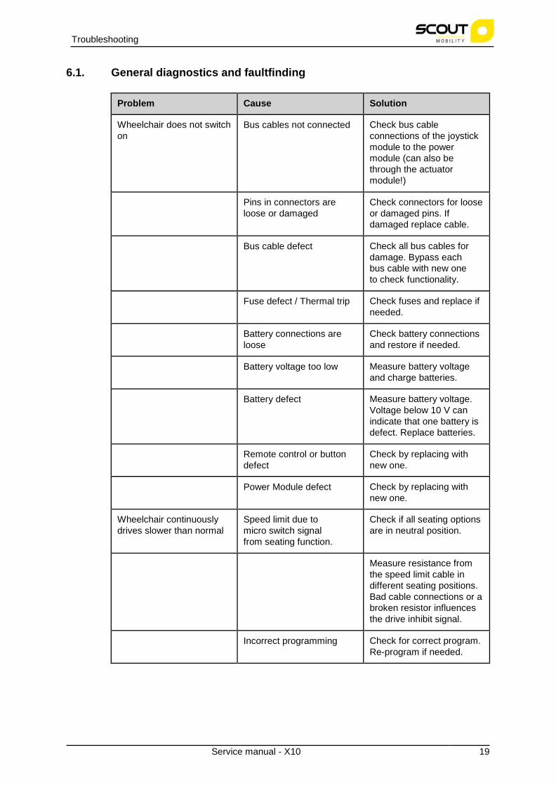
6.1. General diagnostics and faultfinding
Problem Cause Solution
Wheelchair does not switch on
Bus cables not connected Check bus cable connections of the joystick module to the power module (can also be through the actuator module!)
Pins in connectors are loose or damaged
Check connectors for loose or damaged pins. If damaged replace cable.
Bus cable defect Check all bus cables for damage. Bypass each bus cable with new one to check functionality.
Fuse defect / Thermal trip Check fuses and replace if needed.
Battery connections are loose
Check battery connections and restore if needed.
Battery voltage too low Measure battery voltage and charge batteries.
Battery defect Measure battery voltage. Voltage below 10 V can indicate that one battery is defect. Replace batteries.
Remote control or button defect
Check by replacing with new one.
Power Module defect Check by replacing with new one.
Wheelchair continuously drives slower than normal
Speed limit due to micro switch signal from seating function.
Check if all seating options are in neutral position.
Measure resistance from the speed limit cable in different seating positions. Bad cable connections or a broken resistor influences the drive inhibit signal.
Incorrect programming Check for correct program. Re-program if needed.

20 Service manual - X10
Troubleshooting
Problem Cause Solution
Parking brake partially engaged
Check parking brake function. Clicking sound at engaging/disengaging should be present. Check temperature of parking brake after driving.
Wheelchair drives slower throughout the day (or after several hours)
Poor batteries Check batteries and battery voltage.
Poor or incomplete battery charging
Check battery charger. Check charging duration with the user.
Thermal rollback (overheating)
Check usage of wheelchair, extreme usage can cause the power module to decrease the maximum currents for protection. Check wheelchair in freewheel mode for extreme resistance on rolling or turning.
(DX2 controls only) Gyro module (if present) is not connected correctly or is not functioning properly => Controllers switch to SystemSlowDown mode.
Check Gyro cabling and/or replace Gyro module.
Wheelchair only drives well for a short period of time.
Current limit is set too low or the controller is underspecified
Check program settings and/or replace controller.
Wheelchair can be powered up, but does not drive.
Parking brakes are in freewheel mode (flash code on remote!)
Set parking brakes to Drive mode.
Drive inhibits active (flash code on remote)
Check program which Drive inhibits are present. Check cabling of Drive inhibits on wheelchair.
Wheelchair has too little power to drive properly
Tyre pressure of drive wheels or castors is too low
Check pressure and inflate if needed. See User manual for correct value.
Programming of speed and Torque Settings is not correct
Check programming and make corrections if needed.

Service manual - X10 21
Troubleshooting
Problem Cause Solution
Programming of Motor Load Compensation is not correct
Check programming and make corrections if needed. Check with manufacturer for correct value.
Wheelchair veers to one side
Programming of Load Compensation is not correct.
Check programming and make corrections if needed.
Motors are not "balanced" Check motor rpm. See motor label for correct value.
Tyre pressure or tyre size left and right are different
Check tyre pressure and tyre size (diameter).
Suspension "hardness" left and right are different.
Check suspensions and make sure left and right side have identical suspension rates.
Carrier is not "in balance" due to mechanical flaws
Check for loose bolts, cracked or worn frame parts. Check height of carrier left and right.
User weight is not in the center of the wheelchair
Check position of user, see if position can be improved. If not possible use veer compensation in program to correct the steering.
Chair stops intermittently High Voltage due to overcharging or driving down slopes with full batteries (regenerative braking). Check battery voltage, drive down slope at lower speed.
Worn carbon brushes Check brushes, replace if needed.
Speed Limit due to micro switch
Check functioning of micro- switch. Due to vibrations or shocks it can temporarily switch to Slowdown mode.
Castor wheels "wobble" at higher speed
Tyre pressure too high. Check tyre pressure and decrease if needed. See user manual for correct value.
Too little load on the castor wheels.
Modify seating setup if possible or decrease tyre pressure.
22 Service manual - X10
Troubleshooting
Problem Cause Solution
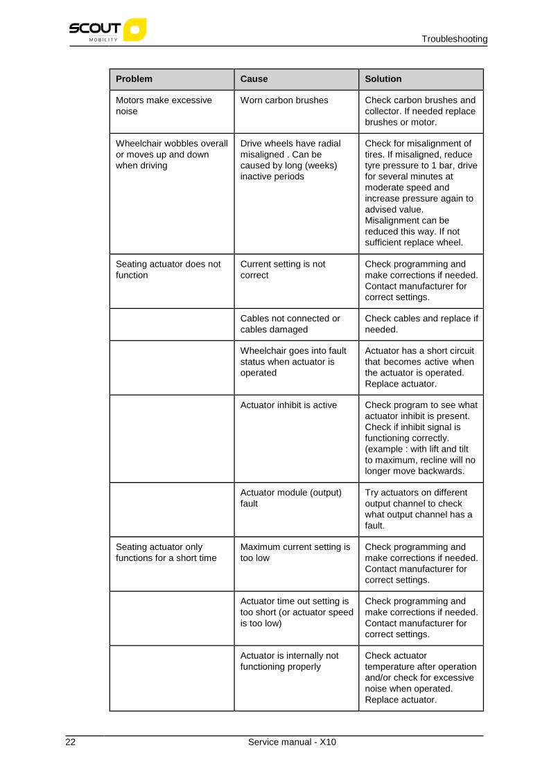
Motors make excessive noise
Worn carbon brushes Check carbon brushes and collector. If needed replace brushes or motor.
Wheelchair wobbles overall or moves up and down when driving
Drive wheels have radial misaligned . Can be caused by long (weeks) inactive periods
Check for misalignment of tires. If misaligned, reduce tyre pressure to 1 bar, drive for several minutes at moderate speed and increase pressure again to advised value. Misalignment can be reduced this way. If not sufficient replace wheel.
Seating actuator does not function
Current setting is not correct
Check programming and make corrections if needed. Contact manufacturer for correct settings.
Cables not connected or cables damaged
Check cables and replace if needed.
Wheelchair goes into fault status when actuator is operated
Actuator has a short circuit that becomes active when the actuator is operated. Replace actuator.
Actuator inhibit is active Check program to see what actuator inhibit is present. Check if inhibit signal is functioning correctly. (example : with lift and tilt to maximum, recline will no longer move backwards.
Actuator module (output) fault
Try actuators on different output channel to check what output channel has a fault.
Seating actuator only functions for a short time
Maximum current setting is too low
Check programming and make corrections if needed. Contact manufacturer for correct settings.
Actuator time out setting is too short (or actuator speed is too low)
Check programming and make corrections if needed. Contact manufacturer for correct settings.
Actuator is internally not functioning properly
Check actuator temperature after operation and/or check for excessive noise when operated. Replace actuator.

Service manual - X10 23
Troubleshooting
Problem Cause Solution
Seating mechanism is moving poorly or with extreme friction
Check mechanisme on loose bolts, cracked or bent parts. Replace parts or modules.
Seating actuator moves in wrong direction (after replacement)
Wiring connections possibly twisted in cable or motor
Change actuator direction in driving program or replace cable or part.
Lighting does not function Cabling not (correctly) connected
Check cabling. See wiring diagrams for correct connections.
Lighting settings not correctly set in program
Check programming and make corrections if needed.
Wheelchair moves/turns very slowly and seems to be lacking power
Load compensation too low, incorrect setting.
Modify load compensation in driving program. Check with manufacturer for correct settings.
Too much load on front castors (RWD).
Modify seating setup to have better weight distribution.
Wheelchair moves very rapidly and jerky
Load compensation is too high.
Modify load compensation in driving program. Check with manufacturer for correct settings.

24 Service manual - X10
Troubleshooting
6.2. Diagnostics and troubleshooting for Shark controls
WARNING! Remove both fuses from the batteries before you change any cables, fuses and/or modules. This way the power way is disconnected from the wheelchair.
NOTICE! For more detailed information about Shark Controllers, specific manuals can be downloaded from the website: www.dynamiccontrols.com.
Problem Cause Solution
Service indicator flashes once
User error. This is probably a 'STALL' timeout.
Put the joystick in neutral and try again.
Service indicator flashes twice
Battery fault. Check batteries and cabling. Charge the batteries or replace them.
The ON-OFF light flashes 3 times.
The left-hand motor (m1) connection is not good.
Check the connection and the cabling.
The left-hand motor (m1) is defect.
Replace this motor.
The ON-OFF light flashes 4 times.
The right-hand motor (m2) connection is not good.
Check the connection and the cabling.
The m2 motor is defect. Replace this motor
The ON-OFF light flashes 5 times
The left-hand parking brake (m1) connection is not good or disconnected.
Check the connection and the cabling.
The left-hand parking brake (m1) is defect.
Replace this motor.
The ON-OFF light flashes 6 times
The right-hand parking brake (m2) connection is not good or disconnected.
Check the connection and the cabling.
The right-hand parking brake (m2) is defect.
Replace this motor.
The ON-OFF light flashes 7 times
Controller fault Check all connections and correct them if needed. If the fault signal is still present after this, replace the controller.
The ON-OFF light flashes 8 times
Power module fault Check all connections and correct them if needed. If the fault signal is still present after this, replace the power module.

Service manual - X10 25
Troubleshooting
Problem Cause Solution
The ON-OFF light flashes 9 times
Communication fault in the Shark system
Check all connections and correct them if needed. If the fault signal is still present after this, replace the controller.
The ON-OFF light flashes 10 times
Unknown fault Check all connections and correct them if needed. If the fault signal is still present after this, contact the Service Department of Scout Mobility BV
The ON-OFF light flashes 11 times
System does not 'fit'. System modules are not compatible.
Check if the controller type corresponds with the power module. Replace one of the two if needed.

26 Service manual - X10
Troubleshooting
6.3. Diagnostics and troubleshooting for DX2 controls
WARNING! Remove both fuses from the batteries before you change any cables, fuses and/or modules. This way the power is disconnected from the wheelchair.
NOTICE! For more detailed information about DX2 Controllers, specific manuals can be downloaded from the website: www.dynamiccontrols.com.
Service manual - X10 27
Troubleshooting
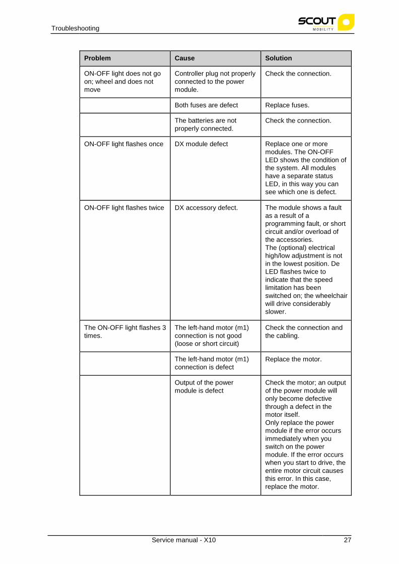
Problem Cause Solution
ON-OFF light does not go on; wheel and does not move
Controller plug not properly connected to the power module.
Check the connection.
Both fuses are defect Replace fuses.
The batteries are not properly connected.
Check the connection.
ON-OFF light flashes once DX module defect Replace one or more modules. The ON-OFF LED shows the condition of the system. All modules have a separate status LED, in this way you can see which one is defect.
ON-OFF light flashes twice DX accessory defect. The module shows a fault as a result of a programming fault, or short circuit and/or overload of the accessories. The (optional) electrical high/low adjustment is not in the lowest position. De LED flashes twice to indicate that the speed limitation has been switched on; the wheelchair will drive considerably slower.
The ON-OFF light flashes 3 times.
The left-hand motor (m1) connection is not good (loose or short circuit)
Check the connection and the cabling.
The left-hand motor (m1) connection is defect
Replace the motor.
Output of the power module is defect
Check the motor; an output of the power module will only become defective through a defect in the motor itself. Only replace the power module if the error occurs immediately when you switch on the power module. If the error occurs when you start to drive, the entire motor circuit causes this error. In this case, replace the motor.

28 Service manual - X10
Troubleshooting
Problem Cause Solution
The ON-OFF light flashes 4 times.
The right-hand motor (m2) connection is not good (loose or short circuit)
Check the connection and the cabling.
The right-hand motor (m2) connection is defect
Replace the motor.
Output of the power module is defect
Check the motor; an output of the power module will only become defective through a defect in the motor itself. Only replace the power module if the error occurs immediately when you switch on the power module. If the error occurs when you start to drive, the entire motor circuit causes this error. In this case, replace the motor.
The ON-OFF light flashes 5 times
The left-hand parking brake (m1) connection is not good or disconnected.
Check the connection and the cabling.
The left-hand parking brake (m1) is defect.
Replace the drive motor.
The ON-OFF light flashes 6 times
The right-hand parking brake (m2) connection is not good or disconnected.
Check the connection and the cabling.
The right-hand parking brake (m2) is defect.
Replace this drive motor.
The ON-OFF light flashes 7 times
The battery voltage is low, or the batteries are flat or bad
Charge the batteries or replace them. NOTE: If the voltage is low (<12 V) the electronics do not work properly. A number of random LEDs of the DX controller flash and the wheelchair will not function.
The ON-OFF light flashes 8 times
The battery voltage is high: above 32 V
This usually occurs during (trickle) charging. Frequent occurrences will result in a defective power module. Correct the charger settings.

Service manual - X10 29
Troubleshooting
Problem Cause Solution
The ON-OFF light flashes 9 times
'BUS low' error: cable breakage in (one of the DX BUS cables) or short circuit in the DX BUS system (entrance to the modules)
Check all cables and module and replace them if needed.
The ON-OFF light flashes 10 times
'BUS high' error: usually a communication error is caused by one of the DX BUS cables or DX modules (entrance to the modules)
Check all cables and module and replace them if needed. If the fault signal is still present after this, contact the Service Department of Scout Mobility BV.
The ON-OFF light flashes 11 times
'STALL' overload error: a motor continuously demands too much power.
Check the drive units. Note: This error is often caused by taking obstacles that are too high, or by driving against walls, and door frames etc. This error may also be caused by a difficult turn from a standing position. Check the weight distribution of the wheelchair.
The ON-OFF light flashes 11 times
System does not 'fit'. System modules are not compatible.
Program the entire drive system for the relevant wheelchair with the aid of the DX-Wizard program on the PC. Always confirm the programming by switching the wheelchair on and off.

30 Service manual - X10
Troubleshooting
6.4. Diagnostics and troubleshooting for R-Net controls
WARNING! Remove both fuses from the batteries before you change any cables, fuses and/or modules. This way the power is disconnected from the wheelchair.
NOTICE! For more detailed information about R-Net Controllers, specific manuals can be downloaded from the website: www.pgdt.com.

Service manual - X10 31
Troubleshooting
Trip Text Trip
code Description
Joystick error - The most common cause of this error is when the joystick is not in the center position when the control system is switched on. The Joystick displaced screen is shown for 5 seconds. If the joystick is not released within this time, the system reports an error. • Make sure that the joystick is in the center
position and re-try to switch on the system.
If the error is still present: the joystick or the joystick module may need to be replaced.
Low Battery - The control system detects that the battery voltage is below 16V. • Check the condition of the batteries and check
the connections to the control system.
If this does not solve the error, the power module may be defect.
High Battery - The control system detects that the battery voltage is above 35 V. Most common reasons for this are: overcharging of the batteries or bad connections between the batteries and the control system. • Check the condition of the batteries and check
the connections to the control system.
If this does not solve the error, the power module may be defect.
M1 Brake Error 1505 The control system detects a problem in the solenoid brakes of the M1 motor or the connection to them. • Check the solenoid brakes, cables and the
connections to the control system.
If this does not solve the error, the power module may be defect.
M2 Brake Error 1506 The control system detects a problem in the solenoid brakes of the M2 motor or the connection to them. • Check the solenoid brakes, cables and the
connections to the control system. If this does not solve the error, the power module may be defect.
M1 Motor Error 3B00 The control system detects that this motor has become disconnected. • Check the motor, cables and the connections to
the control system. .
If this does not solve the error, the power module may be defect
32 Service manual - X10
Troubleshooting
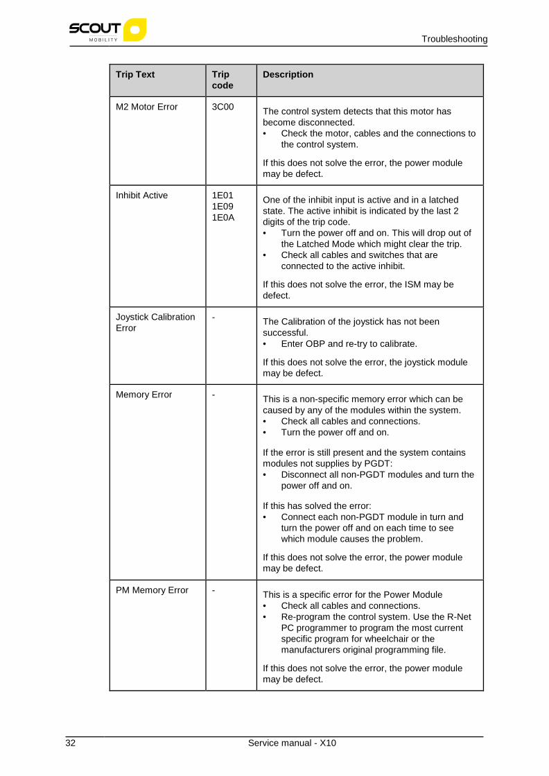
Trip Text Trip code
Description
M2 Motor Error 3C00 The control system detects that this motor has become disconnected. • Check the motor, cables and the connections to
the control system.
If this does not solve the error, the power module may be defect.
Inhibit Active 1E01 1E09 1E0A
One of the inhibit input is active and in a latched state. The active inhibit is indicated by the last 2 digits of the trip code. • Turn the power off and on. This will drop out of
the Latched Mode which might clear the trip. • Check all cables and switches that are
connected to the active inhibit.
If this does not solve the error, the ISM may be defect.
Joystick Calibration Error
- The Calibration of the joystick has not been successful. • Enter OBP and re-try to calibrate.
If this does not solve the error, the joystick module may be defect.
Memory Error - This is a non-specific memory error which can be caused by any of the modules within the system. • Check all cables and connections. • Turn the power off and on.
If the error is still present and the system contains modules not supplies by PGDT: • Disconnect all non-PGDT modules and turn the
power off and on.
If this has solved the error: • Connect each non-PGDT module in turn and
turn the power off and on each time to see which module causes the problem.
If this does not solve the error, the power module may be defect.
PM Memory Error - This is a specific error for the Power Module • Check all cables and connections. • Re-program the control system. Use the R-Net
PC programmer to program the most current specific program for wheelchair or the manufacturers original programming file.
If this does not solve the error, the power module may be defect.

Service manual - X10 33
Troubleshooting
Trip Text Trip code
Description
Gone to Sleep - The control system has been left inactive for a longer period of time than the time indicated by the Sleep Timer. An entry is made in the log each time this occurs. The control system "wake up" again when the joystick or a button is used.
Charging - The control system detects that a charger is connected to Inhibit 1 or to in Inhibit 3. The Battery charger screen is shown during charger connection. An entry is made in the system log each time this occurs.
If the On-Board charger is used: • Disconnect the charger from the AC supply.
If an Off-Board charger is used: • Disconnect the charger from the wheelchair.
If this error is still present when the charger is disconnect, the joystick module may be defect.

34 Service manual - X10
Troubleshooting
6.5. Diagnostics and troubleshooting for VR2 controls
WARNING! Remove both fuses from the batteries before you change any cables, fuses and/or modules. This way the power way is disconnected from the wheelchair.
NOTICE! For more detailed information about VR2 Controllers, specific manuals can be downloaded from the website: www.pgdt.com.
The number of LEDs on the battery indicator indicates the type of fault.

Service manual - X10 35
Troubleshooting
Fault signal/problem Cause Solution
1 LED The battery needs charging or there is a bad connection to the battery.
Check the battery connections and recharge the battery.
2 LEDs The left-hand motor (m1) connection is not good.
Check the connection and the cabling.
3 LEDs The left-hand motor (m1) has a short circuit connection to the battery.
Contract your supplier.
4 LEDs The right-hand motor (m2) connection is not good.
Check the connection and the cabling.
5 LEDs The right-hand motor (m2) has a short circuit connection to the battery.
Contact your supplier.
6 LEDs An external signal prevents the wheelchair from driving.
The external cause depends on the type of wheelchair, one possibility is that the battery charger is still connected.
7 LEDs Joystick fault. Make sure that the joystick is in the center position and re-try to switch on the system.
8 LEDs Control system fault. Check all connections and cables.
9 LEDs The parking brakes have a bad connection.
Check the connections of the parking brake and of the motor.
10 LEDs An excessive voltage has been applied to the control system. This is usually cause by a poor battery connection.
Check the battery connections.
7 LEDs + Speed indicator Communication fault. Check the connection and the condition of the joystick cable.
8 LEDs + Actuator indicator Actuator trip If more than one actuator is installed, check which one in not working correctly. Check the actuator cabling.
Wheelchair moves slow or slugglish
Battery in poor condition Check the battery
Setting for maximum speed is too low.
Adjust the setting for maximum speed.

36 Service manual - X10
Troubleshooting
Fault signal/problem Cause Solution
Speed / profile indicator ripples up and down
The controls system is locked.
Unlock the controls system (see the user manual of the controls system).
Speed / profile indicator flashes
The speed of the wheelchair is being limited for safety reasons.
The external cause depends on the type of wheelchair, most common cause is that the seat is in the elevated position.
Actuator LED flashes The actuator may be inhibited in one or both directions to prevent a unstable setting of the wheelchair. Most likely the user has put another setting (like: lift) in a maximum position.
Put the other settings in a neutral position.

Service manual - X10 37
Cable and module schemes
7. Cable and module schemes
7.1. Shark controls
7.2. DX2 controls
7.3. VR2 controls

38 Service manual - X10
Cable and module schemes
7.4. R-Net controls

Service manual - X10 39
Cable and module schemes

40 Service manual - X10
Cable and module schemes

Service manual - X10 41
Cable and module schemes
8. Version history
Version Release date Changes

Appendices
42 Service manual - X10
9. Appendices

PartsX10
V1.0 from 01-03-2017

© 2017 Scout Mobility BV
All rights reserved.The information provided herein may not be reproduced and/or published in any form, by print, photoprint, microfilm or any othermeans whatsoever (electronically or mechanically) without the prior written authorization of Scout Mobility BV.The information provided is based on general data concerning the constructions known at the time of the publication of thismanual. Scout Mobility BV executes a policy of continuous improvement and reserves the right to changes and modifications.The information provided is valid for the product in its standard version. Scout Mobility BV cannot be held liable for possibledamage resulting from specifications of the product deviating from the standard configuration.The available information has been prepared with all possible diligence, but Scout Mobility BV cannot be held liable for possibleerrors in the information or the consequences thereof. Scout Mobility BV accepts no liability for loss resulting from work executedby third parties.Names, trade names, etc. used by Scout Mobility BV may not, as per the legislation concerning the protection of trade names, beconsidered as being available.

3

4

DrawingO:\ScoutMobility\160956\Software\Scout-mobility-BVBA-Database-20170102\Doku\logo.pngnotfound!
TABLE OF CONTENTS
000-00-X10 Wheel Chair X10001-00-X10 Carrier Standard001-01-X10 Motorarm, Motors001-02-X10 Drive Wheels & Mudguards001-03-X10 Castor Wheels & Mudguards001-04-X10 Covers001-05-X10 Batteries & Chargers002-00-X10 Seating System Standard002-01-1-X10 Armrests (1)002-01-2-X10 Armrests (2)002-02-X10 Legrest Standard002-03-X10 Legrest Comfort002-04-X10 Legrest Powered002-05-X10 Joystick Bracket002-06-X10 Backrest Frame & Electronics Cover002-07-X10 Mechanical & Powered Recline002-08-X10 Backrest Mounting002-08-01-X10 Backrests002-09-X10 Legrest Mounting002-10-X10 Seat Cushion Mounting002-10-01-X10 Seat Cushions003-00-X10 Lift-Tillt Modules003-01-X10 Lift-Tillt Module
X10-EN/NP
789
1011121314151617181920212223242829303536
5

TABLE OF CONTENTS
X10-EN/NP6

000-00-X10 - Wheel Chair X10
Drawing nr. Description
001-00-X10 Carrier Standard
002-00-X10 Seating System Standard
003-00-X10 Lift-Tillt Modules
X10-EN/NP General terms and conditions for sale see page 3 7

X10-EN/NP
001-00-X10 - Carrier Standard
Drawing nr. Description
001-01-X10 Motorarm, Motors
001-02-X10 Drive Wheels & Mudguards
001-03-X10 Castor Wheels & Mudguards
001-04-X10 Covers
001-05-X10 Batteries & Chargers
General terms and conditions for sale see page 38

001-01-X10 - Motorarm, Motors
Pos. Partno. Description
1 4100674 Suspension Rubber Set
2 4100465 Anti Tip Set Complete (1 side)
3 4100190 Anti-Tipper Wheel Set
4 4100432 Motor 10 km/h Type A R-net & VR2
4 4100433 Motor 10 km/h Type B R-net & VR2
4 4100434 Motor 12.5 km/h Type A R-net & VR2
4 4100435 Motor 12.5 km/h Type B R-net & VR2
4 4100608 Motor 10 km/h Type A DX2 & Shark
4 4100609 Motor 10 km/h Type B DX2 & Shark
4 4100610 Motor 12.5 km/h Type A DX2 & Shark
4 4100611 Motor 12.5 km/h Type B DX2 & Shark
5 4100673 Motor Carbon Brush Set, 5 mm
6 4100612 Side Frame B (RWD, Left)
6 4100613 Side Frame A (RWD, Right)
X10-EN/NP General terms and conditions for sale see page 3 9
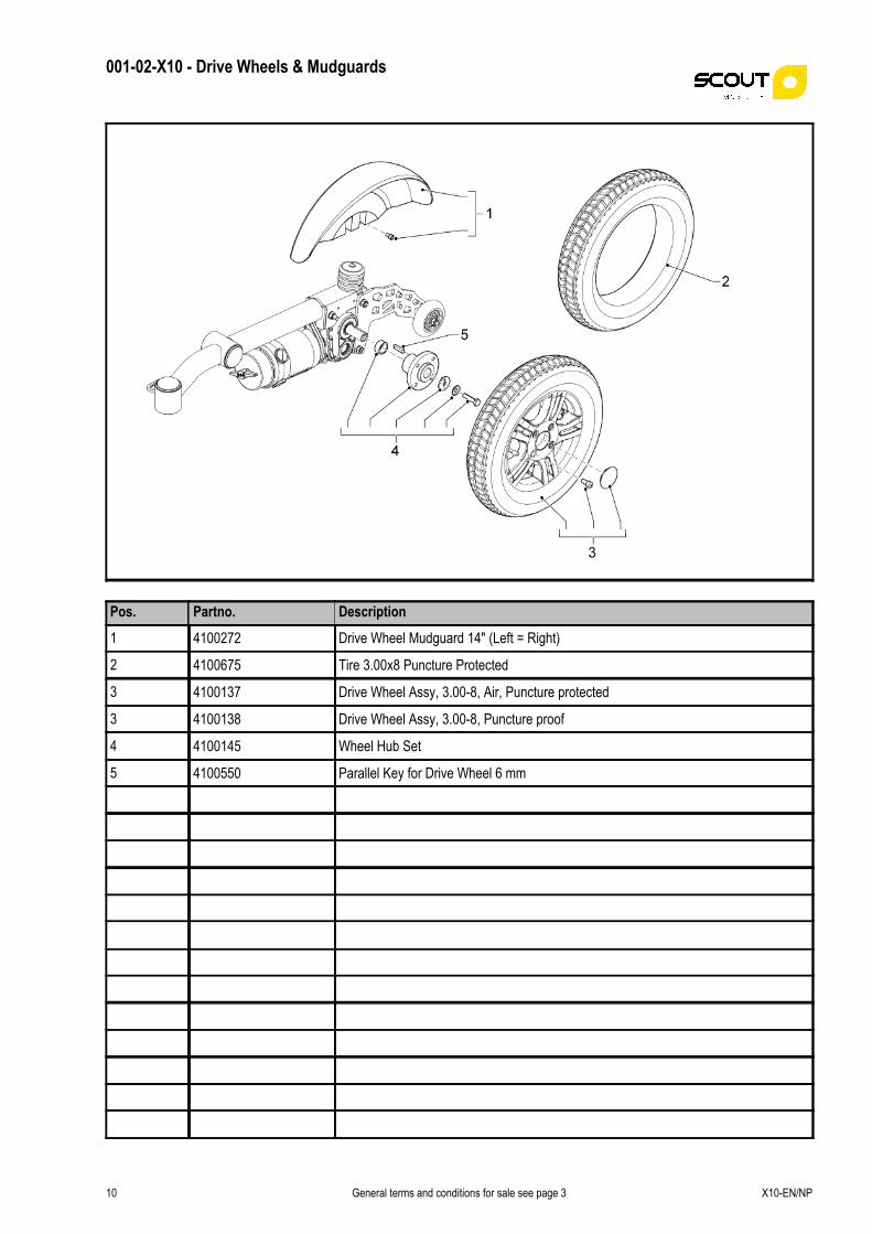
001-02-X10 - Drive Wheels & Mudguards
X10-EN/NP
Pos. Partno. Description
1 4100272 Drive Wheel Mudguard 14" (Left = Right)
2 4100675 Tire 3.00x8 Puncture Protected
3 4100137 Drive Wheel Assy, 3.00-8, Air, Puncture protected
3 4100138 Drive Wheel Assy, 3.00-8, Puncture proof
4 4100145 Wheel Hub Set
5 4100550 Parallel Key for Drive Wheel 6 mm
General terms and conditions for sale see page 310
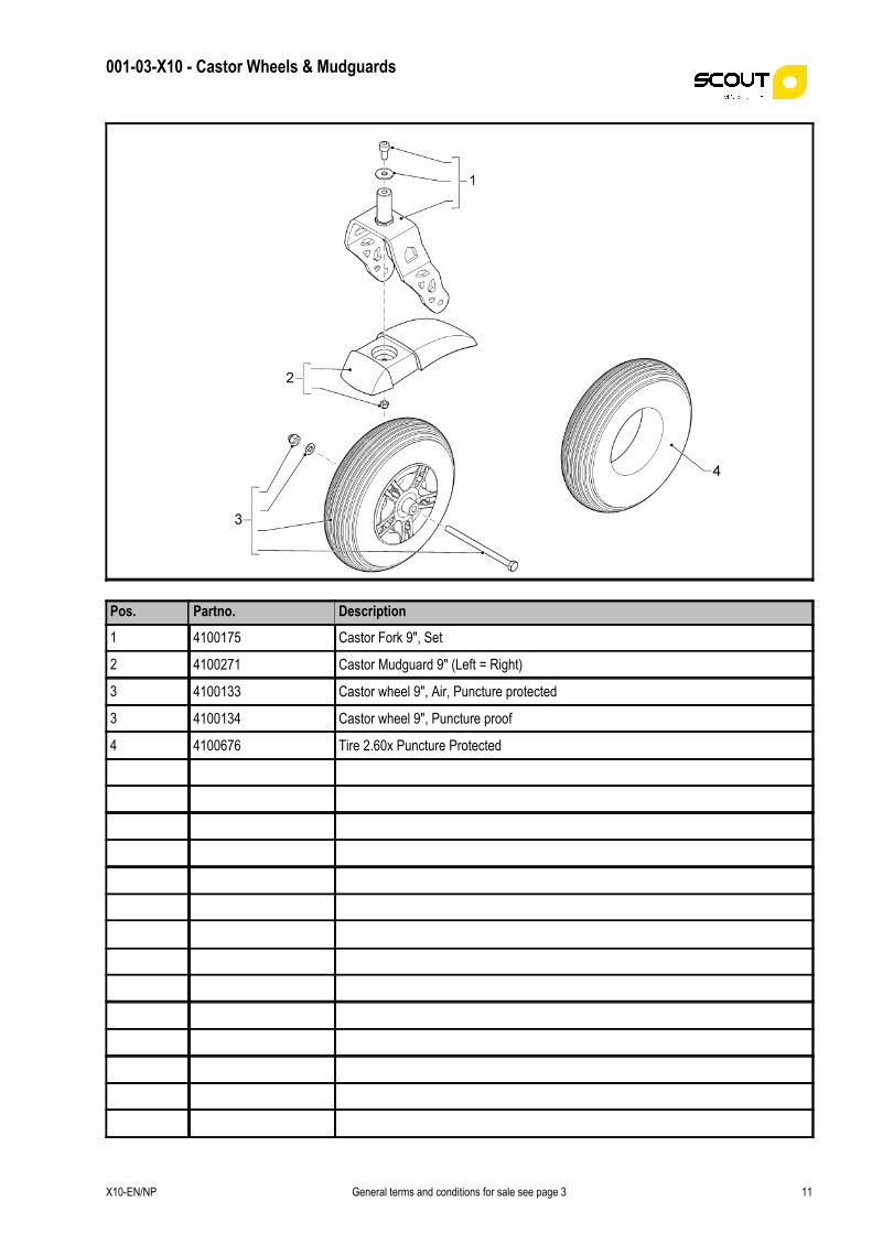
001-03-X10 - Castor Wheels & Mudguards
Pos. Partno. Description
1 4100175 Castor Fork 9", Set
2 4100271 Castor Mudguard 9" (Left = Right)
3 4100133 Castor wheel 9", Air, Puncture protected
3 4100134 Castor wheel 9", Puncture proof
4 4100676 Tire 2.60x Puncture Protected
X10-EN/NP General terms and conditions for sale see page 3 11

001-04-X10 - Covers
X10-EN/NP
Pos. Partno. Description
1 4100475 Battery Cover Standard Frame
2 4100607 Bearing Cover Set Yellow
3 4100477 Cover Power Module Standard frame
General terms and conditions for sale see page 312

001-05-X10 - Batteries & Chargers
Pos. Partno. Description
1 4100586 Battery Charger 24 V, 8 A
2 4100677 Adaptor Socket UK
3 4100280 Battery 50 Ah (C20) AGM
3 4100281 Battery 60 Ah (C20) Gel
3 4100282 Battery 78 Ah (C20) Gel
4 4100376 Battery Strap
X10-EN/NP General terms and conditions for sale see page 3 13
X10-EN/NP
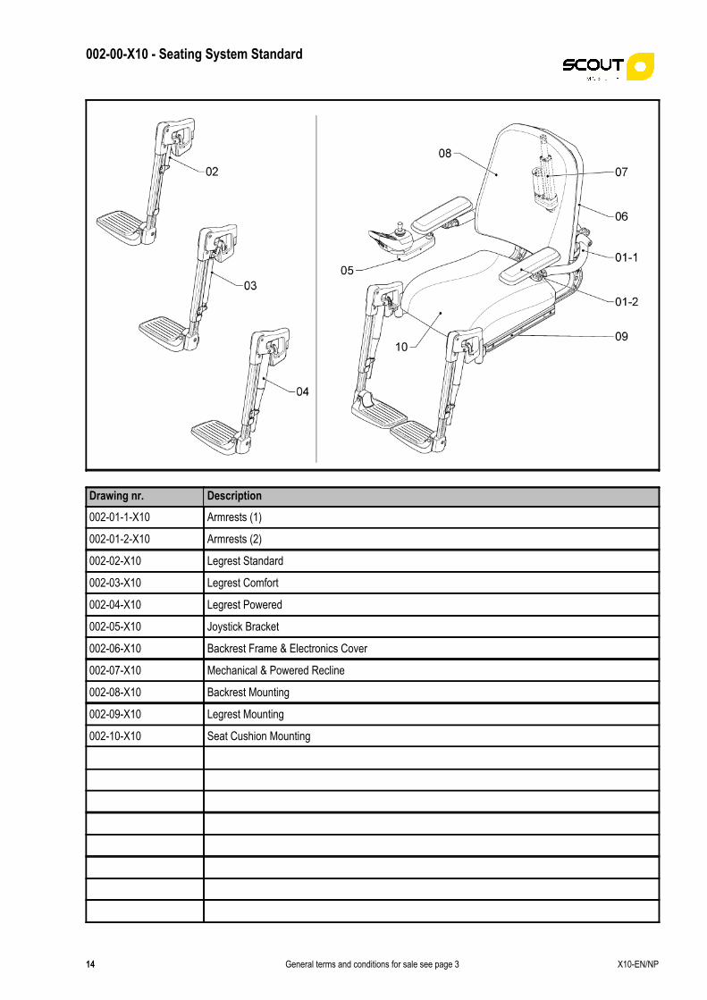
002-00-X10 - Seating System Standard
Drawing nr. Description
002-01-1-X10 Armrests (1)
002-01-2-X10 Armrests (2)
002-02-X10 Legrest Standard
002-03-X10 Legrest Comfort
002-04-X10 Legrest Powered
002-05-X10 Joystick Bracket
002-06-X10 Backrest Frame & Electronics Cover
002-07-X10 Mechanical & Powered Recline
002-08-X10 Backrest Mounting
002-09-X10 Legrest Mounting
002-10-X10 Seat Cushion Mounting
General terms and conditions for sale see page 314

002-01-1-X10 - Armrests (1)
Pos. Partno. Description
1 4100398 Arm Rest Adjuster Block
2 4100395 Arm Rest Height Lever Standard
3 4101053 Bearing Set Arm Rests
4 4100397 Arm Rest Height Adjuster Set
5 4100150 Arm Rest Axle
6 4100491 Arm Rest Left
7 4100492 Arm Rest Right
8 4100678 Side Profile Set (1 side)
9 4100410 Width Adjuster Bracket
10 4100130 Side Mounting Profile Seat
X10-EN/NP General terms and conditions for sale see page 3 15

002-01-2-X10 - Armrests (2)
X10-EN/NP
Pos. Partno. Description
1 4100671 Arm Pad P-Shape Left Upholstered
1 4100672 Arm Pad P-Shape Right Upholstered
2 4100620 Arm Pad 40 cm Upholstered
3 4100619 Arm Pad 30 cm Upholstered
4 4100403 Arm Rest Extrusion Profile
5 4100592 Arm Rest Angle Adjuster Set Right
6 4100591 Arm Rest Angle Adjuster Set Left
General terms and conditions for sale see page 316

002-02-X10 - Legrest Standard
Pos. Partno. Description
1 4100593 Leg Rest Upper Part Right
1 4100594 Leg Rest Upper Part Left
2 4100656 Leg Rest Angle Adjuster Set
3 4100045 Lower Leg Rest Part (Left & Right)
X10-EN/NP General terms and conditions for sale see page 3 17

002-03-X10 - Legrest Comfort
X10-EN/NP
Pos. Partno. Description
1 4100593 Leg Rest Upper Part Right
1 4100594 Leg Rest Upper Part Left
2 4100679 Gasspring Set for 1 Leg rest
3 4100095 Gasspring Locking Lever
4 4100059 Gasspring Comfort Leg Rest
5 4100045 Lower Leg Rest Part (Left & Right)
General terms and conditions for sale see page 318

002-04-X10 - Legrest Powered
Pos. Partno. Description
1 4100593 Leg Rest Upper Part Right
1 4100594 Leg Rest Upper Part Left
2 4100058 Actuator Powered Leg Rest
3 4100045 Lower Leg Rest Part (Left & Right)
X10-EN/NP General terms and conditions for sale see page 3 19

002-05-X10 - Joystick Bracket
X10-EN/NP
Pos. Partno. Description
1 4100389 Remote Arm Rest Bracket
2 4100379 Remote Swing Away Module
3 4100539 Fixed Remote Bracket
4 4100388 Remote Mounting Bracket
General terms and conditions for sale see page 320

002-06-X10 - Backrest Frame & Electronics Cover
Pos. Partno. Description
1 4100429 Cover Electronics
2 4100373 Adjustment Slider Seat Depth
3 4100417 Recline Support weld assy
4 4100427 Back Rest Frame Standard Complete
X10-EN/NP General terms and conditions for sale see page 3 21

002-07-X10 - Mechanical & Powered Recline
X10-EN/NP
Pos. Partno. Description
1 4100545 Mechanical Recline Set
2 4100606 Quick Release Pin
3 4100428 Actuator Back Rest Recline
General terms and conditions for sale see page 322

002-08-X10 - Backrest Mounting
Pos. Partno. Description
1 002-08-01-X10 Backrests
2 4100680 Back Rest Cushion Mounting Set
X10-EN/NP General terms and conditions for sale see page 3 23

002-08-01-X10 - Backrests
X10-EN/NP
Pos. Partno. Description
1 4100710 Contour Backrest Special
1 4100711 Contour Backrest with adjustable horizontal straps Special
1 4100712 Contour Backrest with Lumbar Support Special
1 4100713 Contour Backrest with vertical elastic straps Special
1 4100722 Deep Contour Backrest FLEX, with adj. horiz. 42x50 Stretch Rubber
1 4100723 Deep Contour Backrest FLEX, with adj. horiz. 42x57 Stretch Rubber
1 4100724 Deep Contour Backrest FLEX, with adj. horiz. 46x50 Stretch Rubber
1 4100725 Deep Contour Backrest FLEX, with adj. horiz. 46x57 Stretch Rubber
1 4100726 Deep Contour Backrest FLEX, with adj. horiz. 50x50 Stretch Rubber
1 4100727 Deep Contour Backrest FLEX, with adj. horiz. 50x57 Stretch Rubber
1 4100728 Deep Contour Backrest FLEX, with adj. horiz. 54x50 Stretch Rubber
1 4100729 Deep Contour Backrest FLEX, with adj. horiz. 54x57 Stretch Rubber
1 4100730 Deep Contour Backrest FLEX, with adj. hor.straps Special
1 4100731 Deep Contour Backrest FLEX, with ad. horiz. 36x45, Agilo Air
1 4100732 Deep Contour Backrest FLEX, with adj. horiz. 36x50, Agilo Air
1 4100733 Deep Contour Backrest FLEX, with adj. horiz. 39x50, Agilo Air
1 4100734 Deep Contour Backrest FLEX, with adj. horiz. 42x50, Agilo Air
1 4100735 Deep Contour Backrest FLEX, with adj. horiz. 42x57, Agilo Air
1 4100736 Deep Contour Backrest FLEX, with adj. horiz. 46x50, Agilo Air
General terms and conditions for sale see page 324

002-08-01-X10 - Backrests
Pos. Partno. Description
1 4100737 Deep Contour Backrest FLEX, with adj. horiz. 46x57, Agilo Air
1 4100738 Deep Contour Backrest FLEX, with adj. horiz. 50x50, Agilo Air
1 4100739 Deep Contour Backrest FLEX, with adj. horiz. 50x57, Agilo Air
1 4100740 Deep Contour Backrest FLEX, with adj. horiz. 54x50, Agilo Air
1 4100741 Deep Contour Backrest FLEX, with adj. horiz. 54x57, Agilo Air
1 4100742 Deep Contour Backrest Special
1 4100743 Deep Contour Backrest with adj hor. straps Special
1 4100744 Deep Contour Backrest with vertical elastic straps 36x45, Agilo Air
1 4100745 Deep Contour Backrest with vertical elastic straps 36x50, Agilo Air
1 4100746 Deep Contour Backrest with vertical elastic straps 39x50, Agilo Air
1 4100747 Deep Contour Backrest with vertical elastic straps 42x50, Agilo Air
1 4100748 Deep Contour Backrest with vertical elastic straps 42x57, Agilo Air
1 4100749 Deep Contour Backrest with vertical elastic straps 46x50, Agilo Air
1 4100750 Deep Contour Backrest with vertical elastic straps 46x57, Agilo Air
1 4100751 Deep Contour Backrest with vertical elastic straps 50x50, Agilo Air
1 4100752 Deep Contour Backrest with vertical elastic straps 50x57, Agilo Air
1 4100753 Deep Contour Backrest with vertical elastic straps 54x50, Agilo Air
1 4100754 Deep Contour Backrest with vertical elastic straps 54x57, Agilo Air
1 4100757 Extra Deep Contour Backrest 36x45, Agilo Air
X10-EN/NP General terms and conditions for sale see page 3 25

002-08-01-X10 - Backrests
X10-EN/NP
Pos. Partno. Description
1 4100758 Extra Deep Contour Backrest 36x50, Agilo Air
1 4100759 Extra Deep Contour Backrest 39x50, Agilo Air
1 4100760 Extra Deep Contour Backrest Special
1 4100761 Extra Deep Contour Backrest, with hor. adj. straps 32x35, Agilo Air
1 4100762 Extra Deep Contour Backrest, with hor. adj. straps 32x40, Agilo Air
1 4100763 Extra Deep Contour Backrest, with hor. adj. straps 37x35, Agilo Air
1 4100764 Extra Deep Contour Backrest, with hor. adj. straps 37x40, Agilo Air
1 4100765 Extra Deep Contour Backrest, with hor. adj. straps 42x50, Agilo Air
1 4100766 Extra Deep Contour Backrest, with hor. adj. straps 42x57, Agilo Air
1 4100767 Extra Deep Contour Backrest, with hor. adj. straps 46x50, Agilo Air
1 4100768 Extra Deep Contour Backrest, with hor. adj. straps 46x57, Agilo Air
1 4100769 Extra Deep Contour Backrest, with hor. adj. straps 50x50, Agilo Air
1 4100770 Extra Deep Contour Backrest, with hor. adj. straps 50x57, Agilo Air
1 4100771 Extra Deep Contour Backrest, with hor. adj. straps 54x50, Agilo Air
1 4100772 Extra Deep Contour Backrest, with hor. adj. straps 54x57, Agilo Air
1 4100795 Lumbar Support Backrest 36x45, Agilo Air
1 4100796 Lumbar Support Backrest 36x50, Agilo Air
1 4100797 Lumbar Support Backrest 39x50, Agilo Air
1 4100798 Lumbar Support backrest 42x50, Agilo Air
General terms and conditions for sale see page 326

002-08-01-X10 - Backrests
Pos. Partno. Description
1 4100799 Lumbar Support backrest 42x57, Agilo Air
1 4100800 Lumbar Support backrest 46x50, Agilo Air
1 4100801 Lumbar Support backrest 46x57, Agilo Air
1 4100802 Lumbar Support backrest 50x50, Agilo Air
1 4100803 Lumbar Support backrest 50x57, Agilo Air
1 4100804 Lumbar Support backrest 54x50, Agilo Air
1 4100805 Lumbar Support backrest 54x57, Agilo Air
1 4100857 Standard Contour Back Rest 36x45, Agilo Air
1 4100858 Standard Contour Back Rest 36x50, Agilo Air
1 4100859 Standard Contour back Rest 39x50, Agilo Air
1 4100962 Support Back Rest 36x45, Agilo Air
1 4100963 Support Back Rest 36x50, Agilo Air
1 4100964 Support Back Rest 39x50, Agilo Air
X10-EN/NP General terms and conditions for sale see page 3 27

002-09-X10 - Legrest Mounting
X10-EN/NP
Pos. Partno. Description
1 4100569 Legrest Harness Powered Leg Rests
2 4100599 Leg Rest Socket Left
3 4100681 Leg Rest Clamping Set (1 side)
4 4100600 Leg Rest Socket Right
General terms and conditions for sale see page 328

002-10-X10 - Seat Cushion Mounting
Pos. Partno. Description
1 002-10-01-X10 Seat Cushions
2 4100682 Seat Cushion Mounting Set
X10-EN/NP General terms and conditions for sale see page 3 29

002-10-01-X10 - Seat Cushions
X10-EN/NP
Pos. Partno. Description
1 4100806 Memory Foam Seat 36x36, Stretch Rubber
1 4100807 Memory Foam Seat 36x36, Agilo Air
1 4100808 Memory Foam Seat 36x44, Stretch Rubber
1 4100809 Memory Foam Seat 36x44, Agilo Air
1 4100810 Memory Foam Seat 39x44, Stretch Rubber
1 4100811 Memory Foam Seat 39x44, Agilo Air
1 4100812 Memory Foam Seat 39x50, Stretch Rubber
1 4100813 Memory Foam Seat 39x50, Agilo Air
1 4100814 Memory Foam Seat 42x48, Stretch Rubber
1 4100815 Memory Foam Seat 42x48, Agilo Air
1 4100816 Memory Foam Seat 42x55, Stretch Rubber
1 4100817 Memory Foam Seat 42x55, Agilo Air
1 4100818 Memory Foam Seat 46x48, Stretch Rubber
1 4100819 Memory Foam Seat 46x48, Agilo Air
1 4100820 Memory Foam Seat 46x55, Stretch Rubber
1 4100821 Memory Foam Seat 46x55, Agilo Air
1 4100822 Memory Foam Seat 50x48, Stretch Rubber
1 4100823 Memory Foam Seat 50x48, Agilo Air
1 4100824 Memory Foam Seat 50x55, Stretch Rubber
General terms and conditions for sale see page 330

002-10-01-X10 - Seat Cushions
Pos. Partno. Description
1 4100825 Memory Foam Seat 50x55, Agilo Air
1 4100826 Memory Foam Seat 54x48, Stretch Rubber
1 4100827 Memory Foam Seat 54x48, Agilo Air
1 4100828 Memory Foam Seat 54x55, Stretch Rubber
1 4100829 Memory Foam Seat 54x55, Agilo Air
1 4100830 Memory Foam Seat Special
1 4100864 Standard Contour Seat 36x36, Agilo Air
1 4100865 Standard Contour Seat 36x44, Agilo Air
1 4100870 Standard Contour Seat 39x44, Agilo Air
1 4100871 Standard Contour Seat 39x50, Agilo Air
1 4100872 Standard Contour Seat 42x48 Agilo Air
1 4100873 Standard Contour Seat 42x55 Agilo Air
1 4100874 Standard Contour Seat 46x48 Agilo Air
1 4100875 Standard Contour Seat 46x55 Agilo Air
1 4100876 Standard Contour Seat 50x48 Agilo Air
1 4100877 Standard Contour Seat 50x55 Agilo Air
1 4100878 Standard Contour Seat 54x48 Agilo Air
1 4100879 Standard Contour Seat 54x55 Agilo Air
1 4100889 Contour Seat Special
X10-EN/NP General terms and conditions for sale see page 3 31

002-10-01-X10 - Seat Cushions
X10-EN/NP
Pos. Partno. Description
1 4100901 Standard Contour Seat 369x36, Agilo Skin
1 4100902 Standard Contour Seat 36x44, Agilo Skin
1 4100903 Standard Contour Seat 39x44, Agilo Skin
1 4100904 Standard Contour Seat 39x50, Agilo Skin
1 4100905 Standard Contour Seat 42x48, Agilo Skin
1 4100906 Standard Contour Seat 42x55, Agilo Skin
1 4100907 Standard Contour Seat 46x48, Agilo Skin
1 4100908 Standard Contour Seat 46x55, Agilo Skin
1 4100909 Standard Contour Seat 50x48, Agilo Skin
1 4100910 Standard Contour Seat 50x55, Agilo Skin
1 4100911 Standard Contour Seat 54x48, Agilo Skin
1 4100912 Standard Contour Seat 54x55, Agilo Skin
1 4100978 Support Seat 36x36, Stretch Rubber
1 4100979 Support Seat 36x36, Agilo Air
1 4100981 Support Seat 36x44, Stretch Rubber
1 4100982 Support Seat 36x44, Agilo Air
1 4100988 Support Seat 39x44, Stretch Rubber
1 4100989 Support Seat 39x44, Agilo Air
1 4100991 Support Seat 39x50, Stretch Rubber
General terms and conditions for sale see page 332

002-10-01-X10 - Seat Cushions
Pos. Partno. Description
1 4100992 Support Seat 39x50, Agilo Air
1 4100993 Support Seat 42x48, Stretch Rubber
1 4100994 Support Seat 42x48, Agilo Air
1 4100995 Support Seat 42x55, Stretch Rubber
1 4100996 Support Seat 42x55, Agilo Air
1 4100997 Support Seat 46x48, Stretch Rubber
1 4100998 Support Seat 46x48, Agilo Air
1 4100999 Support Seat 46x55, Stretch Rubber
1 4101000 Support Seat 46x55, Agilo Air
1 4101001 Support Seat 50x48, Stretch Rubber
1 4101002 Support Seat 50x48, Agilo Air
1 4101003 Support Seat 50x55, Stretch Rubber
1 4101004 Support Seat 50x55, Agilo Air
1 4101005 Support Seat 54x48, Stretch Rubber
1 4101006 Support Seat 54x48, Agilo Air
1 4101007 Support Seat 54x55, Stretch Rubber
1 4101008 Support Seat 54x55, Agilo Air
1 4101038 Webbed Seat 42x48, Agilo Skin
1 4101039 Webbed Seat 42x55, Agilo Skin
X10-EN/NP General terms and conditions for sale see page 3 33

002-10-01-X10 - Seat Cushions
X10-EN/NP
Pos. Partno. Description
1 4101040 Webbed Seat 46x48, Agilo Skin
1 4101041 Webbed Seat 46x55, Agilo Skin
1 4101042 Webbed Seat 50x48, Agilo Skin
1 4101043 Webbed Seat 50x55, Agilo Skin
1 4101044 Webbed Seat 54x48, Agilo Skin
1 4101045 Webbed Seat 54x55, Agilo Skin
1 4101046 Webbed Seat Special
General terms and conditions for sale see page 334

003-00-X10 - Lift-Tillt Modules
Drawing nr. Description
003-01-X10 Lift-Tillt Module
X10-EN/NP General terms and conditions for sale see page 3 35

003-01-X10 - Lift-Tillt Module
X10-EN/NP
Pos. Partno. Description
1 4100367 Powered Seat Lift-Tilt Module
General terms and conditions for sale see page 336