Service Manual Trucks - · PDF fileService Manual Trucks Group 884–500 SRS Airbag,...
84
Service Manual Trucks Group 884–500 SRS Airbag, Safety Belts and Bunk Restraints VN, VHD PV776-TSP144851
Transcript of Service Manual Trucks - · PDF fileService Manual Trucks Group 884–500 SRS Airbag,...

Service ManualTrucks
Group 884–500
SRS Airbag, Safety Belts and Bunk Restraints
VN, VHD
PV776-TSP144851


Foreword
The descriptions and service procedures contained in this manual are based on de-signs and methods studies carried out up to April 2001.
The products are under continuous development. Vehicles and components producedafter the above date may therefore have different specifications and repair methods.When this is believed to have a significant bearing on this manual, supplementary ser-vice bulletins will be issued to cover the changes.
The new edition of this manual will update the changes.
In service procedures where the title incorporates an operation number, this is a refer-ence to an S.R.T. (Standard Repair Time).
Service procedures which do not include an operation number in the title are for gen-eral information and no reference is made to an S.R.T.
The following levels of observations, cautions and warnings are used in this ServiceDocumentation:
Note: Indicates a procedure, practice, or condition that must be followed in order tohave the vehicle or component function in the manner intended.
Caution: Indicates an unsafe practice where damage to the product could occur.
Warning: Indicates an unsafe practice where personal injury or severe damage to theproduct could occur.
Danger: Indicates an unsafe practice where serious personal injury or death could oc-cur.
Volvo Trucks North America, Inc.Greensboro, NC USA
Order number: PV776-TSP144851
© 2001 Volvo Trucks North America, Inc., Greensboro, NC USA
All rights reserved. No part of this publication may be reproduced, stored inretrieval system, or transmitted in any forms by any means, electronic, me-chanical, photocopying, recording or otherwise, without the prior writtenpermission of Volvo Trucks North America, Inc..


ContentsGeneral ........................................................................ 3
SRS Airbag, Safety Belts and Bunk Restraints ......... 3
Specifications ............................................................. 5SRS Components, Torque Values ............................. 5Safety Belts and Bunk Restraints, Torque Values ..... 5
Tools ............................................................................ 7Special Tools .............................................................. 7Other Special Equipment ........................................... 8
Design and Function .................................................. 9Safety Belts and Bunk Restraints ................................ 9Supplemental Restraint System (SRS) ...................... 10
System Overview ..................................................... 10Supplemental Restraint System (SRS) Compo-nents ......................................................................... 11
SRS Control Unit (ECU) ........................................ 11Control Unit Connector .......................................... 12Airbag Module ........................................................ 13Airbag Module Connector ...................................... 14Contact Reel .......................................................... 14SRS Indicators (vehicles built prior to 3/99) .......... 15SRS Indicators (vehicles built from 3/99) .............. 16Diagnostic System with Fault Codes ..................... 17SRS Wiring Harness .............................................. 17
Supplemental Restraint System (SRS) Wiring Dia-gram ......................................................................... 18
Troubleshooting ........................................................ 21General Work Practices ........................................... 21Test Resistor, Checking ............................................ 21Connecting the Test Resistor ................................... 22Reading Fault Codes ............................................... 23MID 232 SID 254 FMI 12 Airbag Control Unit,Component Failure ................................................... 30MID 232 SID 1 FMI 6 Igniter Loop, CurrentHigh/Short Circuit ..................................................... 31
MID 232 SID 1 FMI 5 Igniter Loop, CurrentLow/Open Circuit ...................................................... 35MID 232 SID 1 FMI 4/3 Igniter Loop, VoltageShorted Low/High ..................................................... 39MID 232 SID 240 FMI 14 SRS Airbag, CrashData Stored .............................................................. 43Faults Which Do Not Generate a Fault Code .......... 44
SRS Lamp Does not Light ..................................... 44SRS Lamp Does not Light and “Not Respond-ing” Message in Diagnostic Display ....................... 44The SRS Lamp is Lighting but no Fault Code isStored ..................................................................... 45
Routines for a Damaged/Faulty Airbag Module ....... 46Safety Belts and Bunk Restraints, Inspection .......... 47
Service Procedures .................................................. 51General Work Practices ........................................... 51After the Airbag Deploys .......................................... 51Airbag Module/Contact Reel, Replacement ............. 52SRS ECU, Replacement .......................................... 57SRS Wiring Harness, Replacement ......................... 59Safety Belt, Replacement (One) .............................. 63
National Seat .......................................................... 63Safety Belt, Replacement (One) .............................. 65
Volvo Seat .............................................................. 65Lower Bunk Restraint, Replacement ...................... 68
VN 420/610/660 ..................................................... 68Lower Bunk Restraint, Replacement ....................... 70
VN 770 ................................................................... 70Upper Bunk Restraint, Replacement ....................... 72
VN 610/660 ............................................................ 72Upper Bunk Restraint, Replacement ....................... 75
VN 770 ................................................................... 75
Feedback
Operation Numbers
1

2

Group 88 SRS Airbag, Safety Belts and Bunk Restraints General
General
SRS Airbag, Safety Belts and Bunk Restraints
W8001290
W8001834
SRS Airbag Safety Belt
This publication contains service information about the safety belts, bunk restraints andsupplemental restraint system. It is intended for use by service technicians who haveattended and received certification in the Volvo Truck Supplemental Restraint Systemclass (88A). The service procedures and fault tracing instructions may only be carriedout by certified technicians. Volvo Trucks North America, Inc. will not assume any liabil-ity whatsoever for damage incurred, either damage to materials or personal injury,which may result if the service procedures are not followed or if the work is carried outby non-certified personnel.
3

4

Group 88 SRS Airbag, Safety Belts and Bunk Restraints Specifications
Specifications
SRS Components, Torque Values
Airbag module 10 ± 2 Nm 89 ± 18 in-lb
Contact reel 5 ± 0.8 Nm 44 in-lb
Control unit 10 ± 2 Nm 89 ± 18 in-lb
Control unit cover 10 ± 2 Nm 89 ± 18 in-lb
Safety Belts and Bunk Restraints, Torque Values
Steering wheel center bolt 85 ± 15 Nm 63 ± 11 ft-lb
Steering column covers 5 ± 0.8 Nm 44 ± 7 in-lb
Safety belt, National seat 68 ± 7 Nm 50 ± 5 ft-lb
Safety belt, Volvo seat 50 ± 10 Nm 37 ± 7 ft-lb
Bunk restraints, floor, roof and rear wall 68 ± 7 Nm 50 ± 5 ft-lb
Bunk restraints, side wall 24 ± 4 Nm 212 ± 35 in-lb
5

6

Group 88 SRS Airbag, Safety Belts and Bunk Restraints Tools
ToolsSpecial Tools
The following tools are required when working on the SRS. They are available fromVolvo.
9988695SRS Test Resistor
VCADS ProDiagnostic Tool
7

Group 88 SRS Airbag, Safety Belts and Bunk Restraints Tools
Other Special EquipmentThe following tools may be required when working on the SRS. Tools beginning with aJ- number are available from Kent-Moore at 1–800–328–6657.
J-39200Fluke 87
Digital Multimeter
J-42449-1Terminal Probe
J-42449-2Terminal Probe
J-38500-1J-38500-2000
Pro-link 9000 andVolvo Data Cartridge
J-38500-2Power/Data Cable
for Pro-link
J-38500-60ADiagnostic Adaptor Cable
for Pro-link
8

Group 88 SRS Airbag, Safety Belts and Bunk Restraints Design and Function
Design and Function
Safety Belts and Bunk RestraintsThe seat safety belts and bunk restraints are the principalsafety device used in the vehicle. The safety belts/bunkrestraints must be worn at all times if the vehicle is inmotion, even if the vehicle is equipped with a SRS sys-tem (airbag). Instructions on proper safety belt/bunkrestraint use can be found in the operator’s manual.
Safety belt assemblies meet FMVSS 209, Type 1 andType 2 requirements. They are recommended for all per-sons weighing over 25 kg (50 lb).
A child restraint system should be used for each childweighing 25 kg (50 lb) or less. It should meet the require-ments of FMVSS 213 “Child Restraint System.” Carefullyread and follow all manufacturer’s instructions on instal-lation and use. Make certain the child remains in therestraint system at all times while the vehicle is in motion.
Safety belts must be properly worn at all times by thedriver and all passengers while the vehicle is inmotion even if the vehicle is equipped with a Supple-mental Restraint System (SRS or airbag). Failure todo so can result in serious personal injury or death inthe event of a collision.
The high mileage associated with heavy trucks, the con-tinual relative movement of the seat with the cab, thepossible contact with the vehicle seat or other parts ofthe cab structure make it crucial to inspect the safetybelt system regularly.
See “Safety Belts and Bunk Restraints, Inspection”page 47 for inspection instructions.
It is critical that any time a vehicle has been involvedin an accident, the safety belt system in use at thetime of the accident must be replaced, including thesleeper bunk restraints if they were in use at the timeof the accident. Failure to replace the safety belt sys-tem may result in serious injury or death. See theOperator’s Manual for correct safety belt usage.
If it is determined that the safety belts/bunk restraintsneed to be replaced, only Volvo replacement partsshould be used. Additionally, if one part of the safety beltor bunk restraint is found to need replacement, the entireassembly must be replaced. See Service Procedures forreplacement instructions.
W8001402
Safety Belt
W8002901
Bunk Restraint
9

Group 88 SRS Airbag, Safety Belts and Bunk Restraints Design and Function
Supplemental Restraint System (SRS)System Overview
The SRS is supplemental protection for use together with the safety belt.
The SRS is designed to reduce the risk of injury to the driver’s face and upper body.Together with the safety belt, the bag helps to prevent the driver from being thrownagainst the steering wheel, windshield, and other hard surfaces in the cab.
W8001291
How SRS WorksThe system consists of an inflatable bag mounted in thecenter of the steering wheel, and a control unit mountedon the bulkhead inside the cab. A chemical based gasgenerator attached to the rear of the bag inflates the bagin the event of a collision.
Sensors in the control unit detect rapid deceleration. Ifthe control unit detects a sufficiently violent deceleration(collision), the system is activated. The gas generatoractivates and fills the bag with a harmless gas within afew hundredths of a second. During a collision, after thebag has been filled, the gas flows out through two holesin the back of the bag. These holes are large enough tolet the airbag collapse slowly, gently catching the driver.
The control unit also contains a standby power unitwhich can supply the system with power for a short timeshould the normal power supply be broken.
Types of CollisionThe Volvo SRS airbag provides increased protection infrontal collisions, where the truck collides with a fixed orheavy object with enough force for the sensors to acti-vate the gas generator, which deploys the bag. Thedamage to the truck is not always proportional towhether the SRS airbag deploys or not.
The SRS airbag is not designed to be activated when the
• collision is from the sides
• collision is from the rear
• accident is a roll-over
• collision is at low speed or against soft objects suchas bushes, snow drifts etc.
This means that the safety belt must always be used.The SRS airbag only provides supplemental protection.
10

Group 88 SRS Airbag, Safety Belts and Bunk Restraints Design and Function
Supplemental Restraint System (SRS) Components
SRS Control Unit (ECU)The Control Unit Contains:
• two deceleration (piezo-electrical) sensors whichsense the deceleration/collision. They detect a com-bination of the magnitude of the G-forces and theduration. In order for the control unit to activate thesystem, it requires both a high G-force and a pro-longed deceleration (collision).
• microprocessors for evaluating the signals from twodeceleration sensors and controlling the deploymentof the airbag module.
• memory function, which stores information concern-ing possible faults in the system even after thevoltage has been broken (this facilitates fault trac-ing).
Control Unit FunctionIf the control unit determines the force and duration of acollision is sufficient to activate the system, it activatesthe electrical igniter, which activates the gas generator,filling the airbag with a harmless gas, and deploying thebag.
The impulses sent by the control unit to deploy theairbag module are in the form of AC voltage signals. Ca-pacitors in the airbag module connector allow thesepulsating signals to pass through, but block DC voltagesignals and static discharge.
For the control unit to function correctly, it is importantthat it is securely attached to the truck cab, otherwise itdoes not register the time from the beginning of the colli-sion but instead from the moment when the control unititself begins to decelerate.
Standby ModeThe control unit contains a standby power unit. Thisstores sufficient power so that the system functions evenif voltage from the battery is broken (or too low: under8.5 volts). The SRS indicator on the dash will illuminateat 7 volts. The power is stored for a few seconds afterthe voltage has been broken. The power is sufficient totrigger the igniter for less than 1 second in the event of acollision where the battery function has been broken.
The control unit will also go into standby mode if thevoltage from the battery is too high (over 36 volts-seenote1); the control unit will still try to operate to fullcapacity. As soon as the voltage is correct, the SRS indi-cators will go out and the system will function normally.
T8006850
SRS control unit
1The SRS ECU will operate at up to 36 volts, but other systems in the vehicle should never be exposed to voltages that high.
11

Group 88 SRS Airbag, Safety Belts and Bunk Restraints Design and Function
Control Unit Ground ConnectionThe control unit’s ground connection is a direct groundto the SRS mounting plate, to which the SRS ECU ismounted with 3 bolts. One of the 3 bolts is attached to aground strap which case-grounds the ECU to the plate.There should be no particles of dirt between the controlunit and the mounting plate. The mounting plate isgrounded to the cab body.
When replacing or installing a new SRS control unit besure the unit is mounted properly, as shown in “SRSECU, Replacement” page 57.
Control Unit Connector
CAUTION
Avoid touching any of the control unit connector pinswhen the connector has been disconnected. Risk forelectrostatic discharge, which can damage the controlunit.
The control unit connector is located on the SRS wiringharness. It is a 90� angled connector that connects thewiring harness to the SRS control unit. It is equippedwith a locking arm.
Before disconnecting the ECU connector, wait at least 3seconds after voltage is removed to make certain powerhas discharged completely.
To disconnect the wiring harness from the control unitthe locking arm (2) must be pulled back from its lockedposition at the locking tab, (1) and pushed back to theunlocked position, shown in the illustration. This alsopushes the connector out of the socket on the controlunit. Then pull gently on the connector until it comescompletely out of the control unit.
To reconnect the wiring harness, carefully insert the con-nector into the control unit and push the locking armback over the connector towards the locking tab (1). Thelatch will lock in place.
W8001322
1) Locking tab2) Locking arm shown in unlocked position. Tolock, move arm in direction of arrow, to thelocking tab.
12

Group 88 SRS Airbag, Safety Belts and Bunk Restraints Design and Function
Airbag ModuleThe airbag module should be replaced every 10 years tomaintain reliability. See “Airbag Module/Contact Reel,Replacement” page 52.
Personal injury risk. Always store a non-deployedairbag module with the metal (underneath) side downand in a place where it will not be handled carelessly.This is to reduce the chances of the airbag beingejected from its storage position if accidentally de-ployed, which could cause serious personal injury ordeath.
W8001294
Airbag Module FunctionThe Airbag Module Contains:
• an electric ignition device (igniter)• gas generator• inflatable bag
In the event of a collision that is of a high enoughG-force and duration, the control unit sends electrical im-pulses to the electric igniter (A) which activates the gasgenerator.
The gas generator (B) in the airbag module is an en-closed unit which is filled with a propellant which forms aharmless gas. When the gas generator is activated, theairbag is very quickly filled by the gas.
The airbag is folded up and lies above the gas genera-tor. A fully inflated bag has a volume of approximately 67liters.
The airbag is made from a strong polyamide weave withtwo evacuation holes. The ventilation through the evacu-ation holes allows the bag to collapse at a suitablespeed that retards the forward movement of the driver.
An airbag module must never be taken apart. At-tempting to take apart an airbag module which hasnot been deployed could deploy the airbag, causingserious personal injury or death.
WARNING
Attempting to take apart an airbag module which hasbeen deployed could cause chemical burns or skin ir-ritation.
W8001292
Airbag module
A Electric igniterB Gas generator
13

Group 88 SRS Airbag, Safety Belts and Bunk Restraints Design and Function
Airbag Module ConnectorThe airbag module connector has two built in capacitors.C1 blocks DC voltage and prevents the igniter from ignit-ing through static electricity or through careless handlingof current. C2 prevents the igniter from activating due tounintentional high-frequency disturbances.
Resistance cannot be measured on the circuit as the ca-pacitor blocks measurement. There is a service hole (1)in the connector to facilitate fault tracing.
Testing the Cable from the AirbagModule Connector• Place two small steel pins (for example needles,
max. diameter 1 mm) in the service hole (1) and inthe connector pin (2) nearest the service hole andperform the measurements on these. Normal resis-tance is 45–50 k.
T8006860
Airbag module connector
Contact ReelThe contact reel completes the connection between thewire harness and the airbag module on the steeringwheel. The contact reel is made up of a coiled ribboncable which makes it possible for the airbag module con-nector to follow the rotation of the steering wheel. Theother cable provides the connection to the control unit.
There are two rings on the contact reel for the horn slipcontacts.
CAUTION
Avoid turning the contact reel more than 3 turns eitherdirection from the centered position. This can damagethe contact reel.
T8006881
Contact reel
14

Group 88 SRS Airbag, Safety Belts and Bunk Restraints Design and Function
SRS Indicators (vehicles built prior to 3/99)
W8001333
SRS indicator lamp and graphic display
SRS Indicator Lamp, prior to 3/99The SRS system is continuously monitored by micropro-cessors in the control unit. If a fault occurs, this is storedin the memory as an active fault code. At the same time,the SRS indicator lamp in the instrument cluster is acti-vated.
When the ignition key is turned ON, the SRS indicatorlamp lights together with the other lamps in the instru-ment cluster and goes out after 10 seconds.
If the SRS indicator lamp does not go out as describedabove, or lights up during driving, there is an active faultin the SRS system (see Troubleshooting).
When the control unit detects a fault, the SRS indicatorlamp lights until the fault is repaired and the inactive faultcode cleared.
Graphic Display, prior to 3/99The instrument cluster is equipped with an LCD displaythat is located to the left of the steering column. ThisGraphic Display is used to display messages and faultsfrom the various electronic control units and componentson the truck.
During normal operation, the SRS indicator lamp in theinstrument cluster will illuminate for 10 seconds after ig-nition. The lamp will go out if the system is functioningnormally.
If a fault is detected in the SRS system, an active faultcode will be logged into the SRS control unit. Then theSRS lamp in the instrument cluster will illuminate. Thefault may be accessed by using the Graphic Display.
SRS faults will be shown in the Graphic Display as ac-tive or inactive. After repairs have been made, the faultwill be shown as inactive. The SRS lamp will remain onuntil the fault is cleared.
15

Group 88 SRS Airbag, Safety Belts and Bunk Restraints Design and Function
SRS Indicators (vehicles built from 3/99)Unlike the earlier instrumentation, there is no SRS indi-cator lamp. The SRS or airbag icon is only shown in thegraphic display (1), and does not appear when the igni-tion key is turned on. The INFO telltale lamp (2) willilluminate at “key on” during the bulb check, along withall the other telltale bulbs in the instrument cluster.
Vehicles equipped with instrumentation built since 3/99will display the airbag icon in the graphic display if a fault(active or inactive) is detected in the SRS system. Addi-tionally, the INFO telltale lamp will illuminate.
W8002902
1 SRS Indicator2 INFO Telltale Lamp
16

Group 88 SRS Airbag, Safety Belts and Bunk Restraints Design and Function
Diagnostic System with Fault CodesThe SRS control unit has a built-in diagnostic system. Amicroprocessor in the control unit continuously monitorsthe SRS system. If an active fault occurs, this is broad-cast on the J1587 data link as an active fault code, andthe SRS indicators in the instrument cluster are illumi-nated. In spite of this, the system will try to activate theairbag in the event of a collision, unless the wire to theSRS module has been damaged. If the SRS lamp re-mains illuminated the SRS should be repaired as soonas possible.
The fault codes can be accessed by using the graphicdisplay in the instrument cluster, or with electronic diag-nostic tools.
The diagnostic socket is located below the dash on theleft hand side.
For more information, refer to Troubleshooting.
W8001310
Diagnostic socket
SRS Wiring HarnessThe SRS wiring harness is a specially designed andmanufactured cable that connects to the cab main wiringharness at one end with wires for power to the ECU, in-dicator lamp and data link. The other end connects toSRS control unit. From the control unit, wires are fed tothe contact reel for the airbag module.
Located under the truck dash, the harness is orange incolor for easy identification.
The SRS wire harness must never be repaired orspliced. With a faulty harness, breakage or short circuit-ing, it must be replaced with a new harness. Otherwise,the system may not function correctly.
See “SRS Wiring Harness, Replacement” page 59.
17

Group 88 SRS Airbag, Safety Belts and Bunk Restraints Design and Function
Supplemental Restraint System (SRS) Wiring Diagram
Wiring Diagram (vehicles built prior to 3/99)
W8002903
Note: Numbers in parentheses are circuit numbers printed on the wire insulation.
18

Group 88 SRS Airbag, Safety Belts and Bunk Restraints Design and Function
Wiring Diagram (vehicles built from 3/99)
W8002904
Note: Numbers in parentheses are circuit numbers printed on the wire insulation.
19

20

Group 88 SRS Airbag, Safety Belts and Bunk Restraints Troubleshooting
TroubleshootingGeneral Work PracticesUnless otherwise stated, the ignition key should be inthe OFF position during troubleshooting.
Damaged wires or connectors in the SRS system mustnever be repaired, spliced or partially replaced. When afault is noted and localized to a certain connector or wireharness, the complete harness must be changed.
WARNING
The white powder residue from a deployed airbag canbe an irritant to skin and tissue. To avoid injury weargloves and a dust mask when handling a deployedmodule, and avoid getting this white powder in eyesor on skin. If skin irritation occurs, immediately flushthe skin with water. Seek medical attention if irritationcontinues.
Test Resistor, CheckingWhen fault tracing and checking the SRS system, it isimportant that there is no fault on the test resistor(9988695). A defective test resistor will cause the diag-nostic system to give false readings and will make faulttracing and checking more difficult.
To be sure that there is no fault in the test resistor, itshould always be checked using an ohmmeter before itis used.
Removing the Short-Circuit ElementBefore checking resistance, remove the short-circuit ele-ment between the test resistor pins as follows:
1 Wear safety glasses during this procedure.
2 Pry against the bottom edge of the element using acotter pin puller or other sharp small diameter tool.
3 Pull the element from the resistor housing, but donot push against the resistor pins. When removingthe element the retainer ring may lift; if so, push theretainer back into place.
W8001352
Removing the short circuit element
21

Group 88 SRS Airbag, Safety Belts and Bunk Restraints Troubleshooting
Measuring the ResistanceUse an ohmmeter to measure the resistance in the testresistor.Measure over the pins as indicated in the illustration.The ohmmeter should show between 1.8 and 2.5 .
• If the Value Agrees:There is no fault on the test resistor.
• If the Value Deviates:
If the ohmmeter reading deviates from the expectedvalue, the test resistor is defective. Discard the testresistor and replace it with a new one.
T8006865
Measure the resistance
Connecting the Test Resistor
To avoid injury, the battery must not be connectedwhen the airbag module is being removed or installed.If the battery is connected, deployment of the airbagmay occur, possibly causing personal injury or death.
Unless otherwise stated in the instructions, the test resis-tor (9988695) should be connected to the airbag moduleconnector when the airbag module has been removed.
If the SRS is connected to supply voltage when anairbag module has been removed (and the test resistoris not connected), a fault will be registered which mustlater be erased.
T8006845
Connect the test resistor to the airbag module con-nector
22

Group 88 SRS Airbag, Safety Belts and Bunk Restraints Troubleshooting
Reading Fault CodesFault codes generated by the SRS control unit are displayed, read and cleared differently depending on the type ofinstrument cluster and electrical system that is installed in the vehicle. Vehicles built prior to 3/99 used a different in-strument cluster and electrical system than vehicles built after that date. For fault code information with each type ofsystem, see “Reading Fault Codes (vehicles built before 3/99)” page 24 or “Reading Fault Codes (vehicles built from3/99)” page 27.
Active Faults
W3000982
When a fault code is generated, there is a risk that theSRS system will not function.
The driver receives a warning that something is faulty ifthe SRS indicator lamp/icon comes on.
The indicator stays active until the active fault condition isrepaired and the fault code cleared. SRS Indicator on dash
Inactive Faults
An active fault becomes inactive when the fault conditionis repaired.
With an inactive fault, the fault is stored in the SRS con-trol unit. If the fault is inactive, the dash indicator will stillcome on.
The dash indicator stays on until the inactive fault code iscleared.
23

Group 88 SRS Airbag, Safety Belts and Bunk Restraints Troubleshooting
Reading Fault Codes (vehicles builtbefore 3/99)
Fault codes should be read with the MPSI Pro-link 9000. The instrument cluster Graphic Display also displays faultcodes. Faults may be displayed as SAE J1587 text messages or numeric codes.
Reading Fault Codes with the Pro-link 9000
1 The Pro-link 9000 with the Volvo cartridge provideseasy diagnosis of faults. The Pro–link includes anadapter for connecting the Pro–link to the diagnosticsocket. The diagnostic socket is located under theleft side of the dash.
2 After connecting the Pro-link, turn the ignition onand follow the menus in the Pro-link to the SRSAirbag menu.
3
W8001321
After the SRS Airbag menu screen, ECU Informa-tion and Diagnostics menus may be selected. ECUInformation provides hardware and software revisionlevels. The Diagnostics menu allows a choice of Ac-tive Codes, Inactive Codes or Clear Codes.
4
W8001324
1 MID description2 SID description3 FMI description4 A = Active; I = Inactive
The number following A or I represents the or-der in which the fault was received.
5 SAE J1587 SID fault code6 SAE J1587 FMI fault code
Record all codes displayed.
5 To display the next stored fault code press the Downbutton.
6 After all faults have been repaired the display willchange to No Active Codes. This means that thefault has become inactive and can be cleared.
24

Group 88 SRS Airbag, Safety Belts and Bunk Restraints Troubleshooting
Reading Fault Codes with the Graphic Display
W8001313
Graphic Display
1 Turn the ignition ON.
2 Press the Mode button on the instrument cluster un-til DIAGNOSTIC MENU is displayed in the graphicdisplay.
3 Use the Up and Down buttons to display DIAGNOS-TIC MESSAGES.
4 When DIAGNOSTIC MESSAGES is displayed,press the SET button. RECEIVING DATA, PLEASEWAIT will be displayed while the systems on theJ1587 data link are polled.
5 When the first message appears, the Set button canbe pressed to toggle the display between the textdescription and the received data (MID, PID, SID orFMI).
a. If the condition that caused the currently dis-played fault still exists, the cluster will displayACTIVE.
W8001346
b. If the condition that caused the currently dis-played fault has been repaired, the clusterdisplay will not change until the diagnosticsmenu is exited and entered again. If the faulthas been successfully repaired, it will displayINACTIVE when the diagnostic messages aredisplayed again.
W8001345
6 Record all codes displayed.
7 To display the next stored fault press the Down but-ton. For more information, see:
Service information on Instrumentation in Group 38.
25

Group 88 SRS Airbag, Safety Belts and Bunk Restraints Troubleshooting
Clearing Fault Codes with a Pro-link:
Faults can be cleared with the Pro-link tool and Volvocartridge.
All codes must be in an inactive state before clearing.
1 Connect the Pro–link to the diagnostic socket lo-cated under the left side of the dash.
2
W8001321
Turn the ignition on and follow the menus in the Pro-link to SRS Airbag.
3 Important: Record all fault codes on the workorderbefore they are cleared. They cannot be retrievedafter clearing.
4 After the SRS Airbag menu screen, select the Diag-nostics menu and Clear Codes.
5 After codes have been successfully cleared, CodesCleared will be displayed on screen.
6 A final check for fault codes should be carried outafter clearing codes.
7 The indicator lamp will go out when all codes arecleared.
Note: Do not clear fault code MID 232 SID 240 FMI 14Program memory, Special instructions. This code ispresent after an SRS ECU has detected a crash. TheSRS ECU, airbag module, contact reel, steering wheeland safety belts must be replaced after a crash. If thebunk restraint was in use, it must also be replaced.
Note: Do not clear fault code MID 232 SID 254 FMI 12Controller #1, bad device. Replace the SRS ECU (see“SRS ECU, Replacement” page 57).
26

Group 88 SRS Airbag, Safety Belts and Bunk Restraints Troubleshooting
Reading Fault Codes (vehicles builtfrom 3/99)
Vehicles built after 3/99 with a Volvo engine, and after 5/99 with other engines, will display the airbag icon in the graphicdisplay (1) if a fault (active or inactive) is detected in the SRS system. The INFO telltale lamp (2) will also illuminate.
W8002902
Using the Graphic Display Control Buttons
To manually interact with the graphic display, the wiper stalk switch on the right-hand side of the steering wheel is used.
T3008810
The following commands are available:
1 “Esc” (Escape) is used to return to the previousmenu and cancel a setting/operation.
2 “↵” or “Select” confirms a highlighted selection of amenu or character.
3 “Up arrow” moves the cursor up and is used whensetting numerical values.
4 “Down arrow” moves the cursor down and is usedwhen setting numerical values.
27

Group 88 SRS Airbag, Safety Belts and Bunk Restraints Troubleshooting
Reading Fault Codes with the Graphic Display
The instrument cluster Graphic Display will display faultcodes. Faults may be displayed as SAE J1587 text mes-sages or numeric codes. To check for fault codes in theSRS system:
1 Turn the key to the ON position.
2 Use the “Esc” button to access the main menustructure.
3 Select “System Diagnostic” ! “Fault Diagnostic” !“Air Bag”.
4 If there is a fault code or codes the following isshown, for example:
Air bag
Controller #1
Component failure
Active � 1 I #
Line 1: Identification of ECULine 2: Identification of parameter/componentLine 3: Identification of fault type
”� 1” shows how many times the fault has beenregistered since the last resetting. If there is no in-formation available for how many times the faultcode has been registered, only Active is shown (thefault remains). Or alternatively Inactive is shown (thefault was there previously).
The arrow in the lower, right-hand corner is shown ifthere is more than one fault code.
5 To switch to numerical format, press the “↵” or“Select” button.
6 Press the “Up” or “Down” arrow buttons to check forany additional fault codes. Record any fault codesfor future reference.
7 To exit, press the “Esc” button as needed to returnto the main menu.
Clearing Fault Codes with the Graphic Display
Note: Any faults must be inactive before they can becleared. All system faults will be cleared, not just SRSfaults.
1 Turn the key to the ON position.
2 Use the “Esc” button to access the main menustructure.
3 Select “Password Input”. Use the “↵” or “Select” and“Up/Down” buttons to enter the 4–digit numericalpassword. The factory default password is 1234. Ifthe vehicle owner has input another password itmust be entered. For more password information,see service information on the Instrumentation inGroup 38.
4 After the password has been entered, select“System Diagnostics” ! “Fault Diagnostics” !“Reset All”.
5
Reset?
Press ↵ FOR 1S
6 Press and hold the “↵” or “Select” button for 1 sec-ond. When the faults are cleared “Data TransferComplete” will be displayed on the graphic displayscreen.
Data transfer
completed
7 To exit, press the “Esc” button as needed to returnto the main menu.
28

Group 88 SRS Airbag, Safety Belts and Bunk Restraints Troubleshooting
Reading/Clearing Fault Codes with VCADS Pro
VCADS Pro is a Windows 95–based tool that can beused to read and clear the SRS ECU (MID 232) faultcodes on vehicles built since 3/99. The following is abrief description of the fault code retrieval/clearingprocess. For more detailed information, see the most re-cent VCADS Pro user manual, or the “help” menu in thetool itself.
W0001632
W8002905
1 Turn the ignition to the ON position.
2 With the VCADS Pro tool properly connected andoperating select “Fault Codes” from the “Service andMaintenance” menu. From this screen, the VCADSPro tool can be used to retrieve or clear fault codesby entering the correct prompts.
3 Before clearing the inactive fault codes, check forfault codes in other vehicle ECUs and record forlater reference. When clearing fault codes, the“Clear all fault codes” request must be selected.When this command is entered, all inactive faultcodes, not just SRS fault codes, will be cleared.
Note: Do not clear fault code MID 232 SID 240 FMI 14.This code is present after an SRS ECU has detected acrash. The SRS ECU, airbag module, contact reel, steer-ing wheel and safety belts must be replaced after acrash. If the bunk restraint was in use, it must also be re-placed.
Note: Do not clear fault code MID 232 SID 254 FMI 12.Replace the SRS ECU (see “SRS ECU, Replacement”page 57).
29

Group 88 SRS Airbag, Safety Belts and Bunk Restraints Troubleshooting
MID 232 SID 254 FMI 12Airbag Control Unit, Compo-nent FailureFault in the Control Unit
Conditions for fault code
The control unit contains, in addition to the sensors, areserve power unit, a power amplifier for triggering theigniter in the airbag module, functions for continuousmonitoring and storing of generated faults both internallyin the control unit as well as the remainder of the system.
If the self-diagnostic system registers a fault in one ofthe internal functions, fault code MID 232 SID 254 FMI12 is generated.
Fault symptoms:No symptoms apart from the SRS indicator(s).
There is a risk that the SRS will not work if this faultcode is generated.
Cause of fault:Internal fault in the control unit.
Action:
Replace the control unit (ECU). See “SRS ECU, Re-placement” page 57 for replacement instructions.
T8006850
30

Group 88 SRS Airbag, Safety Belts and Bunk Restraints Troubleshooting
MID 232 SID 1 FMI 6Igniter Loop, CurrentHigh/Short CircuitAirbag Module, Short Circuit
NEVER use an ohmmeter or other live measuring in-strument to measure the resistance of the airbagmodule. This practice could cause the airbag to de-ploy, causing serious injury or death.
Condition for fault code:
If the resistance is too low in the airbag module or in thecable circuit (short circuiting between the cables) faultcode MID 232 SID1 FMI 6 is stored.
Fault symptoms:
No fault symptoms other than the SRS indicator. Thereis a risk that the SRS will not work with this fault code.
Cause of fault:
Short circuiting in the ignition cable or the connectorbetween the airbag module and the control unit. Alterna-tively, short circuiting in the airbag module (too low aresistance in the igniter) or in the contact reel.
Action
To be able to find the cause of the fault, troubleshootaccording to the following procedures. Follow the proce-dures carefully. Do not skip over an item before thecause of the fault is localized.
See “Routines for a Damaged/Faulty Airbag Module”page 46 concerning the handling of a damaged airbagmodule.
T8006872
Airbag module
31

Group 88 SRS Airbag, Safety Belts and Bunk Restraints Troubleshooting
Fault Code MID 232 SID 1 FMI 6
Driver Side Igniter Loop, Current High/Short Circuit
Before disconnecting or connecting the airbag mod-ule, turn the ignition key OFF and remove the batteryground cable.
CAUTION
If there are other ground cables connected to the bat-tery (such as engine ECU, satellite system, etc.),disconnect those grounds first, then remove the bat-tery ground cable. Electronic modules may bedamaged when additional grounds are con-nected/disconnected without the main battery groundconnected. Always disconnect the main batteryground last.
Remove the airbag module and install the test resistorwhen troubleshooting the wiring harness for the SRSsystem. Failure to do so could cause the airbag to de-ploy during troubleshooting, causing serious personalinjury or death.
WARNING
To avoid injury, the battery must not be connectedwhen the airbag module is being removed or installed.If the battery is connected, deployment of the airbagmay occur, possibly causing personal injury or death.
Step 1Setup
• Ignition OFF.
• Disconnect the negative lead from the battery.
• Remove the airbag module.
• Check resistance of test resistor 9988695 (see “Test Resistor, Checking” page 21). If resistance is ok, connect theresistor to the connector where the airbag module was removed.
• Ignition ON (Ignition position).
• Re-connect the battery negative lead.
Check Symptom Cause Correction
No active fault code. Short circuiting in the airbagmodule.
Change the airbagmodule.
Read the fault codes.
The same fault code,MID 232 SID1 FMI 6,is displayed.
There is no fault in theairbag module, con-tinue with step 2.
32

Group 88 SRS Airbag, Safety Belts and Bunk Restraints Troubleshooting
Step 2Setup
• Ignition OFF.
• Remove test resistor 9988695.
Check Value Cause Correction
Approx. 45-50k.
Bad test resistor. Check test resistor. Ifbad, replace and re-peat check.
Measure the resistanceacross 1 and 2 on theairbag module connec-tor.
W8001334
0 . Short circuiting in theignition cable, contactreel or ECU.
Disconnect the igni-tion cable from thecontact reel, and re-peat the check at theairbag module con-nector. If 0 replacethe contact reel. Ifopen circuit, continuewith step 3.
Step 3Check Value Cause Correction
45-50 k Bad contact reel. Change the con-tact reel.
W8001343
Disconnect the ignition cablefrom the contact reel andmeasure resistance between ter-minals 1 and 2 on the ignitioncable connector.
0 Short circuiting inthe ignition cableor ECU.
Check the cableharness (go tostep 4).
Step 4Check Value Cause Correction
OL or OC(open circuit).
Ignition cable isok. ECU possiblybad.
Check ECU (goto step 5).
W8001343
Disconnect the ignition cablefrom the ECU and measure re-sistance between terminals 1 and2 on the ignition cable connector.
0 . Short circuiting inthe ignition cable.
Replace the ca-ble harness.
33

Group 88 SRS Airbag, Safety Belts and Bunk Restraints Troubleshooting
Step 5Setup
• Ignition OFF.
• Remove SRS ECU.
Check Value Cause Correction
Approx. 45-50k.
Short circuiting in theignition cable, contactreel or airbag module.
Recheck the ignitioncable, contact reeland test resistor. Aftera recheck of the sys-tem shows the othercomponents are ok,replace the airbagmodule.
Measure the resistance between pins 10 and 11on the ECU connector. Use tool J-42449-2 to con-nect test leads to pins 10 and 11.
Anything out-side 45-50 k.
Bad ECU. Replace ECU.
After Fault Tracing/Repair - Con-necting the BatteryWhen all the components in the cab have been rein-stalled, turn the ignition switch to the ON position andreconnect the battery, heeding the warnings below:
Note: Leave the passenger side window open becausethe power locks may lock the doors when the battery isreconnected.
WARNING
Personal injury risk. Make sure that no one is insidethe cab and that the ignition switch is in the ON posi-tion when connecting the battery, and that the cabdoors and driver side window are closed. Otherwise,personal injury may result due to possible deploymentof the airbag.
CAUTION
Connect the negative battery lead, then connect anyadditional ground cables back to the battery (if addi-tional ground cables were connected to the battery,such as engine ECU, satellite system, etc.). Other-wise, electronic modules may be damaged whenadditional grounds are connected/disconnected with-out the main battery ground connected. Alwaysconnect the main battery ground first.
T8006863
34

Group 88 SRS Airbag, Safety Belts and Bunk Restraints Troubleshooting
MID 232 SID 1 FMI 5Igniter Loop, CurrentLow/Open CircuitAirbag Module, Breakage
NEVER use an ohmmeter or other live measuring in-strument to measure the resistance of the airbagmodule. This practice could cause the airbag to de-ploy, causing serious injury or death.
Conditions for fault code:
If the resistance is too low in the airbag module or in thecable circuit (breakage in the cable) fault code MID 232SID 1 FMI 5 is stored.
Fault symptoms:
No fault symptoms other than the SRS indicator illumi-nates. There is a risk that the SRS will not work with thisfault code.
Cause of fault:
Breakage in the ignition cable or connector between theairbag module and the control unit. Alternatively, break-age in the airbag module (resistance too high in theigniter) or in the contact reel.
Action
To be able to find the cause of the fault, troubleshootaccording to the following procedures. Follow the proce-dures carefully. Do not skip over an item before thecause of the fault is localized.
See “Routines for a Damaged/Faulty Airbag Module”page 46 concerning the handling of a damaged airbagmodule.
T8006872
35

Group 88 SRS Airbag, Safety Belts and Bunk Restraints Troubleshooting
Fault Code MID 232 SID 1 FMI 5
Driver Side Igniter Loop, Current Low/Open Circuit
Before disconnecting or connecting the airbag mod-ule, turn the ignition key OFF and remove the batteryground cable.
CAUTION
If there are other ground cables connected to the bat-tery (such as engine ECU, satellite system, etc.),disconnect those grounds first, then remove the bat-tery ground cable. Electronic modules may bedamaged when additional grounds are con-nected/disconnected without the main battery groundconnected. Always disconnect the main batteryground last.
Remove the airbag module and install the test resistorwhen troubleshooting the wiring harness for the SRSsystem. Failure to do so could cause the airbag to de-ploy during troubleshooting, causing serious personalinjury or death.
WARNING
To avoid injury, the battery must not be connectedwhen the airbag module is being removed or installed.If the battery is connected, deployment of the airbagmay occur , possibly causing personal injury or death.
Step 1Setup
• Ignition OFF.
• Disconnect the battery negative lead.
• Remove the airbag module.
• Disconnect the connector from the airbag module.
• Check resistance of test resistor 9988695 (see “Test Resistor, Checking” page 21). If resistance is ok, connect thetool to the connector where the airbag module was removed.
• Ignition ON (Ignition position).
• Re-connect the battery negative lead.
Check Symptom Cause Correction
No active fault code. Breakage in the airbag module. Change the airbagmodule.
Read off the fault codes.
The same fault code,MID 232 SID 1 FMI 5,is displayed.
There is no fault in theairbag module, con-tinue with step 2.
36

Group 88 SRS Airbag, Safety Belts and Bunk Restraints Troubleshooting
Step 2Setup
• Ignition OFF.
• Disconnect test resistor 9988695.
• Disconnect the contact reel.
Check Value Cause Correction
OL or OC(open circuit).
Bad contact reel. Change the con-tact reel.
With the ignition cable disconnected from the contact reel,measure resistance between the terminals on the contactreel. Measure with one probe at the airbag module con-nector and the other probe at the ignition cable terminalon the contact reel.
0 . Bad ignition cable. Check the cableharness (go tostep 3).
Step 3Check Value Cause Correction
45-50 k. Bad contact reel. Check the con-tact reel (go backto step 2).
W8001343
Measure resistance across ter-minals 1 and 2 on the ignitioncable connector.
OL or OC(open circuit).
Open circuit in theignition cable orECU.
Check the cableharness (go tostep 4).
Step 4Setup
• Ignition OFF.
• Disconnect the ignition cable from the ECU
Check Value Cause Correction
Measure resistance across ter-minal 1 on the ignition cableconnector to terminal 10 at theECU connector. Use tool J-42449-1 to connect a test lead toterminal 10.
OL or OC(open circuit).
Bad cable harness. Replace the ca-ble harness.
Measure resistance across ter-minal 2 on the ignition cableconnector to terminal 11 at theECU connector. Use tool J-42449-1 to connect a test lead toterminal 11.
W8001343
0 . Possible bad ECU. Check the ECU(go to step 5).
37

Group 88 SRS Airbag, Safety Belts and Bunk Restraints Troubleshooting
Step 5Setup
• Ignition OFF.
• Remove SRS ECU.
Check Value Cause Correction
Approx. 45-50k.
Short circuiting in theignition cable, contactreel or airbag module.
Recheck the ignitioncable, contact reeland airbag module.
Measure the resistance between terminals 10 and11 on the ECU connector. Use tool J-42449-2 toconnect test leads to terminals 10 and 11.
Anything out-side 45-50 k.
Bad ECU. Replace ECU.
After Fault Tracing/Repair - Con-necting the BatteryWhen all the components in the cab have been rein-stalled, turn the ignition switch to the ON position andreconnect the battery, heeding the warnings below:
Note: Leave the passenger side window open becausethe power locks may lock the doors when the battery isreconnected.
WARNING
Personal injury risk. Make sure that no one is insidethe cab and that the ignition switch is in the ON posi-tion when connecting the battery, and that the cabdoors and driver side window are closed. Otherwise,personal injury may result due to possible deploymentof the airbag.
CAUTION
Connect the negative battery lead, then connect anyadditional ground cables back to the battery (if addi-tional ground cables were connected to the battery,such as engine ECU, satellite system, etc.). Other-wise, electronic modules may be damaged whenadditional grounds are connected/disconnected with-out the main battery ground connected. Alwaysconnect the main battery ground first.
T8006863
38

Group 88 SRS Airbag, Safety Belts and Bunk Restraints Troubleshooting
MID 232 SID 1 FMI 4/3Igniter Loop, Voltage ShortedLow/HighAirbag Module, Short Circuiting to Volt-age or to Ground
Conditions for fault code:
The control unit checks if the signal is continuously highor continuously low (0 V) in the cable circuit, whichmeans short circuiting to voltage or to ground. If this isthe case, fault code MID 232 SID 1 FMI 4 Driver IgniterLoop, Voltage Shorted Low or MID 232 SID 1 FMI 3Driver Igniter Loop, Voltage Shorted High will be gener-ated.
Fault symptoms:
No fault symptoms other than the SRS indicator illumi-nates. There is a risk that the SRS will not work with thisfault code.
Cause of fault:
Short circuiting to voltage or ground in the ignition cableor the connector between the airbag module and theSRS ECU. Alternatively, short circuiting to voltage orground in the airbag module (resistance too low in theigniter) or in the contact reel.
Action
To be able to find the cause of the fault, troubleshootaccording to the following procedures. Follow the proce-dures carefully. Do not skip over an item before thecause of the fault is localized.
See “Routines for a Damaged/Faulty Airbag Module”page 46 concerning the handling of a damaged airbagmodule.
T8006872
39

Group 88 SRS Airbag, Safety Belts and Bunk Restraints Troubleshooting
Fault Code MID 232 SID 1 FMI 4/3
Driver Side Igniter Loop, Voltage Shorted Low/High
Before disconnecting or connecting the airbag mod-ule, turn the ignition key OFF and remove the batteryground cable.
CAUTION
If there are other ground cables connected to the bat-tery (such as engine ECU, satellite system, etc.),disconnect those grounds first, then remove the bat-tery ground cable. Electronic modules may bedamaged when additional grounds are con-nected/disconnected without the main battery groundconnected. Always disconnect the main batteryground last.
Remove the airbag module and install the test resistorwhen troubleshooting the wiring harness for the SRSsystem. Failure to do so could cause the airbag to de-ploy during troubleshooting, causing serious personalinjury or death.
WARNING
To avoid injury, the battery must not be connectedwhen the airbag module is being removed or installed.If the battery is connected, deployment of the airbagmay occur, possibly causing personal injury or death.
Step 1Setup
• Ignition OFF.
• Disconnect the battery negative lead.
• Disconnect the airbag module.
• Check resistance of test resistor 9988695 (see “Test Resistor, Checking” page 21). If resistance is ok, connect thetool to the connector where the airbag module was removed.
• Ignition ON (Ignition position).
• Connect the battery negative lead.
Check Symptom Cause Correction
No active fault code. Short circuiting to voltage orground in the airbag module.
Change the airbag mod-ule.
The same fault code,SID 1 FMI 4, is shown.
Continue with step 2.
Read off the fault codes.
The same fault code,SID 1 FMI 3, is shown.
There is no fault in the airbagmodule.
Skip to step 3.
40
Group 88 SRS Airbag, Safety Belts and Bunk Restraints Troubleshooting
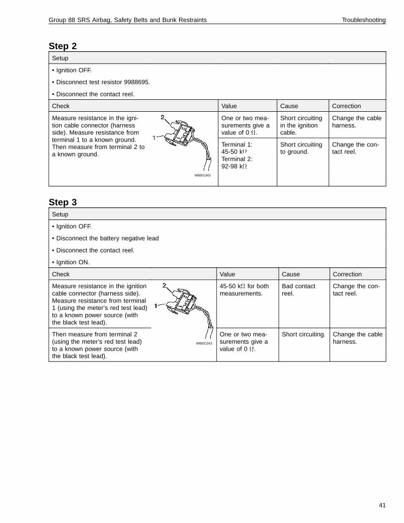
Step 2Setup
• Ignition OFF.
• Disconnect test resistor 9988695.
• Disconnect the contact reel.
Check Value Cause Correction
One or two mea-surements give avalue of 0 .
Short circuitingin the ignitioncable.
Change the cableharness.
W8001343
Measure resistance in the igni-tion cable connector (harnessside). Measure resistance fromterminal 1 to a known ground.Then measure from terminal 2 toa known ground.
Terminal 1:45-50 kTerminal 2:92-98 k
Short circuitingto ground.
Change the con-tact reel.
Step 3Setup
• Ignition OFF.
• Disconnect the battery negative lead
• Disconnect the contact reel.
• Ignition ON.
Check Value Cause Correction
Measure resistance in the ignitioncable connector (harness side).Measure resistance from terminal1 (using the meter’s red test lead)to a known power source (withthe black test lead).
45-50 k for bothmeasurements.
Bad contactreel.
Change the con-tact reel.
Then measure from terminal 2(using the meter’s red test lead)to a known power source (withthe black test lead).
W8001343
One or two mea-surements give avalue of 0 .
Short circuiting. Change the cableharness.
41

Group 88 SRS Airbag, Safety Belts and Bunk Restraints Troubleshooting
After Fault Tracing/Repair - Con-necting the BatteryWhen all the components in the cab have been rein-stalled, turn the ignition switch to the ON position andreconnect the battery, heeding the warnings below:
Note: Leave the passenger side window open becausethe power locks may lock the doors when the battery isreconnected.
WARNING
Personal injury risk. Make sure that no one is insidethe cab and that the ignition switch is in the ON posi-tion when connecting the battery, and that the cabdoors and driver side window are closed. Otherwise,personal injury may result due to possible deploymentof the airbag.
CAUTION
Connect the negative battery lead, then connect anyadditional ground cables back to the battery (if addi-tional ground cables were connected to the battery,such as engine ECU, satellite system, etc.). Other-wise, electronic modules may be damaged whenadditional grounds are connected/disconnected with-out the main battery ground connected. Alwaysconnect the main battery ground first.
T8006863
42

Group 88 SRS Airbag, Safety Belts and Bunk Restraints Troubleshooting
MID 232 SID 240 FMI 14SRS Airbag, Crash Data StoredConditions for fault code
If the SRS ECU registers a crash condition, fault codeMID 232 SID 240 FMI 14 is generated.
Note that this fault code’s description appears differentlyin the Pro-link and instrument cluster. In the Pro-link, thefault code is described as SRS Airbag, Crash EventStored, special instructions. In the instrument cluster, itmay be either way shown below:
D AIRBAG
I UNKNOWN
A SPECIAL INSTRUCTIONS
G
N
ACTIVE
Air bag
Program memory
Unknown fault
Active � 1 I #
Action:
Replace the SRS ECU, contact reel, wiring harness,airbag module, steering wheel and safety belts (includingthe bunk restraint, if it was in use). See Service Proce-dures for more information.
T8006850
43

Group 88 SRS Airbag, Safety Belts and Bunk Restraints Troubleshooting
Faults Which Do Not Generatea Fault CodeCertain faults can occur without receiving any direct information via a fault code. To find the cause of the fault, faulttracing must be carried out step by step.
SRS Lamp Does not LightConditions for Fault (vehicles built before 3/99)
The lamp should normally illuminate when the ignition isON and go out after 10 seconds.
During that 10 seconds, the SRS self diagnosis is beingcarried out. After the self diagnosis is complete, the con-trol unit reduces the voltage to the indicating circuit (toapproximately 0.8-2.0 V) and the lamp goes out. Whenthe lamp is on, there is a voltage of approximately 12 Von the cable.
Conditions for Fault (vehicles built after 3/99)
The INFO lamp (and all other telltales) should illuminate3–5 seconds when the ignition key is turned to ON toverify that the telltale bulbs operate.
Fault Symptom
1 The SRS/INFO lamp is always out.
Cause of Fault:
Indicator lamp broken
Incorrect voltage or improper ground in the instru-ment cluster.
SRS Lamp Does not Light and“Not Responding” Message inDiagnostic DisplayVehicles built before 3/99 only1 The SRS lamp does not illuminate if the SRS is not
installed in the vehicle.
2 It also does not illuminate to indicate a breakage inthe J1587 data link (with the breakage occurring be-fore the vehicle ignition is ON). (The lamp will stillilluminate to indicate other faults, and for 10 sec-onds at ignition.)
For these conditions, when performing a diagnostic teston a vehicle without SRS, the SRS diagnostic menu inthe Pro-link / instrument cluster will display SRSAIRBAG, NOT RESPONDING.
If condition 2 occurs, check the data link connectionsand wiring.
W3000982
SRS lamp
44

Group 88 SRS Airbag, Safety Belts and Bunk Restraints Troubleshooting
The SRS Lamp is Lighting butno Fault Code is StoredConditions for Fault (vehicles built before 3/99 only)
The lamp should normally illuminate when the ignition isturned ON and go out after 10 seconds.
During that 10 seconds, the SRS self diagnosis is beingcarried out. After the self diagnosis is complete, the con-trol unit reduces the voltage to the indicating circuit (toapprox. 0.8-2.0 V) and the lamp goes out. When thelamp is on, there is a voltage of approx. 12 V on the ca-ble.
With either a too low or too high battery voltage (< 8.5volts or > 36 volts-see note2) the indicator lamp (SRSlamp) will light up, at the same time the control unit goesinto standby mode, which means that the control unit willtry to provide full function. As soon as the voltage is cor-rect, the indicator lamp goes out and the systemfunctions normally, but with, for example, undervoltage itwill take a longer time to charge up the energy reserve.There is no fault code stored for incorrect battery voltage.
The SRS indicator lamp can be illuminated even if thecontrol unit is faulty, or with a breakage in the indicatorlamp wire between the control unit and instrument clus-ter.
Conditions for Fault (vehicles built after 3/99)
The INFO lamp (and all other telltales) should illuminate3–5 seconds when the ignition key is turned to ON toverify that the telltale bulbs operate. With no power toSRS ECU the INFO lamp will illuminate and and theSRS icon will appear on the graphic display. When ac-cessed, the graphic display will read “AIR BAG, MID232, NOT RESPONDING”.
Fault Symptom
1 The SRS lamp is always on with no fault code (vehi-cles built before 3/99 only)
2 INFO indicator and SRS icon are always on with nofault code (vehicles built after 3/99 only).
Cause of Fault:
Open circuit on the ECU power supply wire
Blown SRS ECU fuse in fuse panel
Open circuit on the SRS indicator lamp wire (vehi-cles built before 3/99 only)
Improper ground connection on SRS ECU
Note: If power has been lost to the ECU, the Pro-linktool will display NOT RESPONDING in the SRS Diag-nostic menu.
W3000982
SRS lamp
2The SRS ECU will operate at up to 36 volts, but other systems in the vehicle should never be exposed to voltages that high. The instrumentcluster, for example, is rated at a maximum operating voltage of 18V.
45

Group 88 SRS Airbag, Safety Belts and Bunk Restraints Troubleshooting
Routines for a Damaged/FaultyAirbag ModuleHandling
An airbag module that has not deployed must not bedetonated or deployed, neither in position in the trucknor when removed from the truck. The module and thecontrol unit must be returned to Volvo. Additionally, ifthere is any damage to the engine tunnel, the controlunit must always be returned.
When removing the unit, refer to “Airbag Mod-ule/Contact Reel, Replacement” page 52.
Storage and Transport
During transport, the airbag module should be handledin accordance with national regulations for transport ofpyrotechnic material.
The airbag module and control unit should be sent backto:
Volvo Truck CorporationAtt: TMA, HaverikommissionenDept. 27273, X-hallenS-405 08 GothenburgSweden
T8006872
46

Group 88 SRS Airbag, Safety Belts and Bunk Restraints Troubleshooting
Safety Belts and Bunk Re-straints, Inspection
Before working on a vehicle, set the parking brakes,place the transmission in neutral and chock thewheels. Failure to do so can result in unexpectedvehicle movement and can cause serious personal in-jury or death.
Failure to properly inspect and maintain safety beltscan cause serious injury or loss of life.
It is critical that any time a vehicle has been involvedin an accident, the safety belt system in use at thetime of the accident must be replaced, including thesleeper bunk restraints if they were in use at the timeof accident. Failure to replace the safety belt systemmay result in serious injury or death.
Safety belts must be inspected at the scheduled pre-ventive maintenance inspection, or more often ifexposed to severe environmental or vocational condi-tions. Failure to replace a worn or damaged seat beltassembly may result in serious injury or death.
Note: If replacement of any part of the seat is indicatedthrough maintenance guidelines below, the entire belt as-sembly must be replaced, both retractor and buckle side.
1
W8001406
Check the web wear at the latch area.The webbing must be closely exam-ined to determine if there are any cuts,fraying or extreme wear in the web-bing. Cuts, frays or excessive wearindicate the need for replacement ofthe safety belt system.
2
W8001405
The D-loop web guide is an areawhere almost constant movement ofthe safety belt webbing occursbecause of the relative movement be-tween the seat and the cab. Becauseof this constant movement this is anarea where wear will often occur. Thewebbing must be closely examined todetermine if there are any cuts, fraysor extreme wear in the webbing. Cuts,frays or excessive wear indicate theneed for replacement of the safety beltsystem.
47

Group 88 SRS Airbag, Safety Belts and Bunk Restraints Troubleshooting
3Check that the D-loop web guide isrotating properly. If the guide is not ro-tating properly, the webbing will pull atthe wrong angle through the guide, ac-celerating wear.
4
W8001403
Check the Komfort Latch for cracks orpossible damage and that it worksproperly.
5
W8001404
Check the buckle by inserting the latchand verify proper operation. Determineif the latch plate is worn or deformed.Check the buckle and latch casing forcracks or breakage.
6
W8001401
The retractor web storage device ismounted on the B—pillar of the vehi-cle. The retractor is the heart of thesafety belt system and can be dam-aged if abused, even unintentionally.Check the retractor web storage de-vice operation to ensure that it is notlocked and that it spools out and re-tracts the webbing properly.
48

Group 88 SRS Airbag, Safety Belts and Bunk Restraints Troubleshooting
7
W8001387
If tethers are being used to anchor thesafety belts to the floor or bunk walls,make sure they are properly attachedto the seat. Tethers must also be in-spected for web wear and propertightness of mounting hardware.
8All hardware for safety belt mountingpoints should be evaluated for corro-sion. All attachment points of thesystem should be checked for tight-ness of mounting hardware.
9Check web in areas exposed to ultravi-olet rays from the sun or extreme dustor dirt. If the original color of the webin these areas is extremely faded, thephysical strength of this web may havedeteriorated. If this condition exists, re-place the system.
10Check the stitching of the bunk re-straint cross hatch webbing for properintegrity. Replace the bunk restraint ifneeded.
49

50

Group 88 SRS Airbag, Safety Belts and Bunk Restraints Service Procedures
Service ProceduresGeneral Work PracticesThe ignition key should always be in the “OFF” positionbefore beginning any repairs, unless otherwise stated.
When an airbag module has been removed, make surethat no particles (metal filings etc) can enter the modulecontact pins (igniter), so cover the terminal opening withtape. It is important that the airbag is stored in a secureplace.
Damage to the wiring or connectors in the SRS mustnever be repaired, spliced or partly replaced. When afault is noted and localized in a certain connector or partof the SRS wiring harness, the complete wire harnessmust be replaced.
Do not turn the steering wheel when the contact reel issecured in the locked position. This can damage thecontact reel (see “Airbag Module/Contact Reel, Replace-ment” page 52).
After the Airbag DeploysAfter a collision where the SRS airbag has deployed,the following components MUST always be replaced:
• Airbag Module
• Steering Wheel
• Contact Reel
• SRS Electronic Control Unit (ECU)
• SRS Wiring Harness
• Safety Belts
• Bunk Restraint (if in use during collision)
51

Group 88 SRS Airbag, Safety Belts and Bunk Restraints Service Procedures
8845-03-02-01Airbag Module/Contact Reel,ReplacementBefore starting any service procedure, see:
• “General Work Practices” page 51
Important: Only certified technicians may work on theSRS.
Before working on a vehicle, set the parking brakes,place the transmission in neutral, and block thewheels. Failure to do so can result in unexpectedvehicle movement and can cause serious personal in-jury or death.
The airbag module must never be taken apart. At-tempting to take apart an airbag module which hasnot been deployed could deploy the airbag, causingserious injury or death.
WARNING
The white powder residue from a deployed airbag canbe an irritant to skin and tissue. To avoid injury weargloves and a dust mask when handling a deployedmodule, and avoid getting this white powder in eyesor on skin. If skin irritation occurs, immediately flushthe skin with water. Seek medical attention if irritationcontinues.
Removal
1Align the vehicle wheels straight andcenter the steering wheel to preventdamage to the new contact reel due tothe limited number of turns available.
2
T8006862
CAUTION
If there are other ground cables connected to the bat-tery (such as engine ECU, satellite system, etc.),disconnect those grounds first, then remove the bat-tery ground cable. Electronic modules may bedamaged when additional grounds are con-nected/disconnected without the main battery groundconnected. Always disconnect the main batteryground last.
Turn the ignition switch OFF and dis-connect the battery.
3If the vehicle has a locking steeringcolumn, turn the ignition switch to theON position to unlock the steeringwheel.
4
W8001304
Loosen the two mounting bolts for theairbag module through the accessholes on the underneath side of thesteering wheel until the airbag modulereleases.
52

Group 88 SRS Airbag, Safety Belts and Bunk Restraints Service Procedures
5
W8001298
Disconnect the airbag module electri-cal connector and remove the airbagmodule.
6
W8001294
Always store a non-deployed airbag module with themetal (underneath) side down and in a place where itwill not be handled carelessly. This is to reduce thechance of the airbag being ejected from its storageposition if accidentally deployed, which could causeserious personal injury or death.
Cover the terminal opening with tapeso that no particles (metal filings, etc.)can enter the module contact pins (ig-niter). It is important that the airbag isstored in a secure place. All airbagmodules being replaced must be re-turned to the manufacturer accordingto current procedures.
7
W8001302
Remove the 2 clips at the bottom ofthe steering column cover.
8
W8001303
Remove the rear steering columncover by removing the 3 torx boltsfrom the cover and sliding the rubbergrommets off of the cover at the stalkswitches. Remove the 3 torx bolts fromthe front cover and remove the cover.
53

Group 88 SRS Airbag, Safety Belts and Bunk Restraints Service Procedures
9
W8001300
W8001429
Unscrew the screw at the end of thecontact reel caution label. Leave thescrew in the label to secure the screwin the contact reel after the steeringwheel is removed.
10
W8001299
Remove the mounting bolt from thecenter of the steering wheel.
11
W8001301
Lift the steering wheel from the shaftwithout turning it. Allow the cable andcontact reel caution label to passthrough the hole in the steering wheel.
12
CAUTION
Failure to secure the contact reel label to the contactreel may result in damage to the contact reel. Do notturn the steering wheel while the contact reel is se-cured. Turning the wheel or shaft can damage thecontact reel. (If installing a new contact reel, disregardthis caution.)
Gently secure the contact reel label tothe contact reel using the screw in theend of the label.
54

Group 88 SRS Airbag, Safety Belts and Bunk Restraints Service Procedures
13
W8001308
Disconnect the connectors for the con-tact reel ignition cable and horncontacts.
14
W8001309
Remove the 3 torx bolts from the con-tact reel.
15
W8001305
Remove the contact reel assembly.
Installation
16
W8001305
Install the new contact reel assemblyonto the steering shaft and tighten the3 torx bolts to 5 ± 0.8 Nm (44 ± 7 in-lb). Connect the connectors for thehorn and the airbag module.
5 ± 0.8 Nm(44 ± 7 in-lb)
17Install the front and rear steering col-umn covers. Torque bolts to5 ± 0.8 Nm (44 ± 7 in-lb). Pull the rub-ber grommets over the covers at thestalk switches. Install the plastic clipsat the bottom of the covers.
55

Group 88 SRS Airbag, Safety Belts and Bunk Restraints Service Procedures
18
W8001306
Remove the locking screw from thecontact reel before installing the steer-ing wheel. Align the 2 studs on thecontact reel and feed the module con-nector through hole in the center ofthe steering wheel. Center the steer-ing wheel and install.
19Install a new bolt in the center of thesteering wheel and torque to85 ± 15 Nm (63 ± 11 ft-lb). Install thecontact reel locking screw (with thecaution label attached) into the steer-ing wheel.
Note: Check to be sure no metal parti-cles are around the airbag connectorpins.
85 ± 15 Nm(63 ± 11 ft-lb)
20Connect the electrical connector fromthe contact reel to the airbag module.Install the airbag to the steering wheel.Secure the airbag with existing bolts inthe steering wheel. Access these boltsfrom the 2 holes in the bottom of thesteering wheel. Torque the bolts to10 ± 1.5 Nm (89 ± 13 in-lb).
10 ± 1.5 Nm(89 ± 13 in-lb)
21
WARNING
Personal injury risk. Make sure that no one is insidethe cab when connecting the battery, and that the cabdoors and driver side window are closed. Otherwise,personal injury may result due to possible deploymentof the airbag.
CAUTION
If there are other ground cables connected to the bat-tery (such as engine ECU, satellite system, etc.),connect the battery ground cable first, then connectthose grounds. Electronic modules may be damagedwhen additional grounds are connected/disconnectedwithout the main battery ground connected.
Turn the ignition switch to the ON posi-tion. Make sure nobody is in the cab.Close the cab windows and doors, butleave the passenger side window openbecause the power locks may lock thedoors when the battery is reconnected.Then connect the negative battery leadand torque to 24–27 Nm (18–20 ft-lb).
22View fault codes to see if any appear.If faults were present before replacingthe components, they are still presentas inactive faults. Clear the inactivefaults.There should be no active fault codesfor the SRS system. If any active faultcodes are present they need to be re-paired.
Note: If either of the fault codes MID232 SID 240 FMI 14 or MID 232 SID254 FMI 12 is present, replace theSRS ECU (see “SRS ECU, Replace-ment” page 57).
56

Group 88 SRS Airbag, Safety Belts and Bunk Restraints Service Procedures
8847-03-02-01SRS ECU, ReplacementBefore starting any service procedure, see:
• “General Work Practices” page 51
Important: Only certified technicians may work on theSRS.
Before working on a vehicle, set the parking brakes,place the transmission in neutral, and block thewheels. Failure to do so can result in unexpectedvehicle movement and can cause serious personal in-jury or death.
Removal
1Turn the ignition switch OFF.
2Remove the lower dash panels, centerand right sections, by removing the 8torx bolts and 4 plastic nuts.
3
W8001295
Remove the 2 torx bolts in the SRSECU cover, and remove the cover.
4
W8001296
Remove the 3 torx bolts from the SRSECU.
5
W8001297
CAUTION
Avoid touching the control unit contact pins. There is arisk of damaging the control unit with electro-staticdischarge.
Disconnect the SRS ECU electricalconnector. Push in on the tab holdingthe connector locking arm to releasethe connector.
57

Group 88 SRS Airbag, Safety Belts and Bunk Restraints Service Procedures
Installation
6Use only Volvo replacement parts andinstall the ECU only in the proper loca-tion described below.
7
W8001296
CAUTION
Avoid touching the control unit contact pins. There is arisk of damaging the control unit with electro-staticdischarge.
Check the SRS ECU mounting platefor proper ground connection (thereshould be no grease, paint or dirt be-tween the mounting plate and the cabbody since the ECU is case-grounded). Install the SRS ECU to themounting plate where the old ECUwas with the 3 torx bolts. Torque to10 ± 2 Nm (88 ± 18 in-lb).
8
W8001322
1) Locking tab
2) Locking arm shown in unlocked position
Connect the SRS ECU electrical con-nector, making certain the locking arm(2) is pulled back onto the locking tab(1), as shown in the illustration.
9Install the cover for the SRS ECU byinstalling one torx bolt on each side ofthe cover. Torque to 10 ± 2 Nm(88 ± 18 in-lb).
10Clear fault codes. There should be noactive fault codes for the SRS system.
11Install the lower dash panel, centerand right sections, with 8 torx boltsand 4 plastic nuts. Torque bolts to3.5 ± 0.5 Nm (31 ± 4.5 in-lb).
3.5 ± 0.5 Nm(31 ± 4.5 in-lb)
58

Group 88 SRS Airbag, Safety Belts and Bunk Restraints Service Procedures
3741-03-02-01SRS Wiring Harness, Replace-mentOnly certified technicians may work on the SRS.
Important: when replacing the SRS (airbag) wiring, theharness must be installed and routed properly. Wiresmay be pinched and broken when the steering column isadjusted if the harness is not routed and secured with tiestraps as shown.
Damage to the wiring or connectors in the SRS mustnever be repaired, spliced or partly replaced. When afault has been noted and localized in a certain connectoror part of the SRS wiring harness, the complete wireharness must be replaced.
Replace all tie straps removed when removing the har-ness.
Failure to follow the routing shown when installing anSRS harness can result in damage to the wiring har-ness, and the SRS may not function, which couldresult in serious injury or death in the event of an ac-cident..
Before working on a vehicle, set the parking brakes,place the transmission in neutral, and block thewheels. Failure to do so can result in unexpectedvehicle movement and can cause serious personal in-jury or death.
Removal
1
CAUTION
Electronic modules may be damaged when additionalgrounds connected to the battery (such as engineECU, satellite system, etc.) are connected /discon-nected without the main battery ground beingconnected. Always disconnect the main batteryground last.
Turn the ignition switch OFF and dis-connect battery ground cables to anyECUs that may be connected to thebattery (such as engine ECU, satellitesystem, etc.). Then remove the batteryground cable.
2Remove the left front grab handle byremoving the bolt cap in the trimpanel, then removing the upper andlower bolts.
3Remove the 3 torx bolts and plasticnut from the lower dash trim panel tothe left of the steering column. Re-move the diagnostic connector andvent hose from the panel, then removethe panel.
4Remove the right front grab handle byremoving the bolt cap in the trimpanel, then removing the upper andlower bolts.
5
W8001464
To remove the right and center lowerdash panels, remove the 8 bolts alongthe top of both panels, and the 3 plas-tic nuts on the bottom of the rightpanel, and the 1 plastic nut from thecenter lower panel.
59

Group 88 SRS Airbag, Safety Belts and Bunk Restraints Service Procedures
6
W8001302
Remove the 2 clips at the bottom ofthe steering column cover.
7
W8001303
Remove the rear steering columncover by removing the 3 torx boltsfrom the cover and sliding the rubbergrommets off of the cover at the stalkswitches.
8Remove the lower section of the steer-ing column cover by pushing thecenters through on the plastic rivetsand removing the rivets.
9
W8001463
Contact reel connector
Disconnect the SRS harness at thecontact reel connector. Cut the tiestraps running down the steering col-umn bracket (3 places), being carefulnot to cut any wires in the main har-ness. Cut the 3 tie straps from thelower bracket. Pull the SRS harnessfrom the main harness on the steeringcolumn. Cut any tie straps fasteningthe SRS harness to the main cab har-ness. Separate the SRS harness fromthe main cab harness between thesteering column and SRS ECU.
60

Group 88 SRS Airbag, Safety Belts and Bunk Restraints Service Procedures
10
W8001465
CAUTION
Risk of damage to the control unit from electro-staticdischarge (ESD). To avoid ESD damage, do not touchthe control unit contact pins and wear an anti–staticwrist strap grounded to the nearest electrical ground.
Cut and remove the tie straps aroundthe SRS ECU, and disconnect theSRS ECU electrical connector. Pushin on the tab holding the connectorlocking arm to release the connector.Remove the SRS harness.
Note: In some early production vehi-cles (built before May 1997), the covermust be removed from the SRS ECUto disconnect the connector. If theconnector cannot be accessed withthe cover on, remove the cover by re-moving the 2 mounting bolts.
Installation
11
W8001322
1) Locking tab
2) Locking arm shown in unlocked position
Connect the SRS ECU electrical con-nector, making certain the locking armis pulled back onto the locking tab.Connect the SRS wiring harness to themain cab harness connector, makingcertain the connector lock is installed.
12If the ECU cover was removed, installit with the 2 mounting bolts. Torque to10 ±2 Nm (88 ±18 in-lb).
13
W8001460
Secure the SRS harness with tiestraps to the fastening clips around theSRS ECU.
14Route the SRS harness along themain cab harness over to the steeringcolumn.
61

Group 88 SRS Airbag, Safety Belts and Bunk Restraints Service Procedures
15
W8001461
Important: Route harness exactly as shown.Use tie straps exactly where shown.
CAUTION
Failure to follow the routing shown when installing anSRS harness can result in damage to the wiring har-ness, and the SRS may not function.
If equipped with tilt steering, adjust thesteering column to the upright posi-tion. Route the SRS harness along thesteering column wiring and connectthe harness connector to the contactreel. Secure the harness using 3 tiestraps along the steering column asshown. Install 3 tie straps on thebracket below the steering column.Secure the SRS harness to the maincab harness between the steering col-umn and SRS ECU.
Important: If equipped with tilt steer-ing, move the steering column tocheck for pulling or pinching of theSRS or main cab harness at the steer-ing column.
16
WARNING
Make sure that no one is inside the cab when con-necting the battery, and that the cab doors and driverside window are closed. Otherwise, personal injury ordeath may result due to possible deployment of theairbag.
CAUTION
If there are other ground cables connected to the bat-tery (such as engine ECU, satellite system, etc.),connect the battery ground cable first, then connectthose grounds. Electronic modules may be damagedwhen additional grounds are connected/disconnectedwithout the main battery ground connected.
Turn the ignition switch to the ON posi-tion. Make sure nobody is in the cab.Close the cab windows and doors, butleave the passenger side window openbecause the power locks may lock thedoors when the battery is reconnected.Then connect the negative battery leadand torque to 24–27 Nm (18–20 ft-lb).
17View faults to see if any fault codesappear. There should be no activefault codes for the SRS system. If anyactive fault codes are present theyneed to be repaired.
18Install the lower steering column cover.Align the weld studs through the holesinto the bottom of the panel. Install theplastic rivets to secure the top of thepanel.
62

Group 88 SRS Airbag, Safety Belts and Bunk Restraints Service Procedures
19
W8001302
Install the rear steering column cover.Torque the 3 bolts to 5 ±0.8 Nm (44±7 in-lb). Position the stalk switches’rubber grommets over the front andrear covers. Install the plastic clips inthe bottom of the covers.
20Install the lower dash panel, centerand right sections. Torque the 8 boltsto 3.5 ±0.5 Nm (31 ±4.5 in-lb). Also in-stall the 4 plastic nuts. Make certain topull the mat back and align the weldstuds through the holes. (Insert A/Cductwork through the center panel.)
21Install the right front grab handle with2 bolts. Torque to 24 ±4 Nm(18 ±3 in-lb). Install the bolt cap in thetrim panel.
22Install the lower left dash trim panelwith 3 bolts and 1 plastic nut at thebottom weld stud. Make certain to in-sert the A/C ductwork and diagnosticconnector.
23Install the left front grab handle with 2bolts. Torque to 24 ±4 Nm(18 ±3 in-lb). Install the bolt cap in thetrim panel.
8841-03-02-01Safety Belt, Replacement (One)
National Seat
It is critical that any time a vehicle has been involvedin an accident, the entire safety belt system must bereplaced in the vehicle (which also includes thesleeper bunk restraints) if they were in use at the timeof the accident. Failure to replace the safety belt sys-tem may result in serious injury or death.
Before working on a vehicle, set the parking brakes,place the transmission in neutral, and block thewheels. Failure to do so can result in unexpectedvehicle movement and can cause serious personal in-jury or death.
When installing safety belt components, do notover-torque or use high-speed pneumatic tools. Doingso may cause anchor point failures, resulting in thepossible failure of the safety belt anchoring system,which can cause serious personal injury or death.
63

Group 88 SRS Airbag, Safety Belts and Bunk Restraints Service Procedures
Removal
1
W8002921
1 Hex box2 Shoulder harness D-ring
Remove the recoiler cover by pullingthe cover from the bottom. With thecover removed, remove the hex bolt(1) from the recoiler.
2Remove the bolt cap and the torx boltfor the shoulder harness D-ring (2).
3
W8002894
1 Hex box2 Bolt3 Hex box4 Bolt
Remove the hex bolt (1) in the outerside of the seat fastening the seat beltbracket and tether belt. Remove thebolt (2) fastening the tether belt to thefloor.
4Remove the hex bolt (3) on the innerside of the seat to remove the buckleassembly and tether belt. Remove thebolt (4) fastening the tether belt to thefloor on the inner side of the seat (seeillustration in previous step).
64

Group 88 SRS Airbag, Safety Belts and Bunk Restraints Service Procedures
Installation
5Install the buckle and tether belt to theinner side of the seat. Then install thebolt for the tether belt in the floor.Torque bolts to 68 ± 7 Nm(50 ± 5 ft-lb).
68 ± 7 Nm(50 ± 5 ft-lb)
6Install the recoiler with the mountingbolt. Install the recoiler cover. Installthe mounting bolt and D-ring. Torquebolts to 68 ± 7 Nm (50 ± 5 ft-lb). Installthe mounting bolt cap.
7Install the safety and tether belt brack-ets to the outer side of the seat.Torque bolts to 68 ± 7 Nm (50 ± 5 ft-lb). Install the tether belt bracket in thefloor, and torque the bolt to 68 ± 7 Nm(50 ± 5 ft-lb).
8841-03-02-01Safety Belt, Replacement (One)
Volvo Seat
It is critical that any time a vehicle has been involvedin an accident, the entire safety belt system must bereplaced in the vehicle (which also includes thesleeper bunk restraints) if they were in use at the timeof the accident. Failure to replace the safety belt sys-tem may result in serious injury or death.
Before working on a vehicle, set the parking brakes,place the transmission in neutral, and block thewheels. Failure to do so can result in unexpectedvehicle movement and can cause serious personal in-jury or death.
When installing safety belt components, do notover-torque or use high-speed pneumatic tools. Doingso may cause anchor point failures, resulting in thepossible failure of the safety belt anchoring system,which can cause serious personal injury or death.
Removal
1Remove the bottom seat cushion bygrasping at the front and rear of thecushion and pulling up.
2
W8001328
Remove the 5 screws from the bottomouter seat side cover.
65

Group 88 SRS Airbag, Safety Belts and Bunk Restraints Service Procedures
3
W8002922
1 and 2 are bolts
Remove the recoiler bolt (1). Removethe trim cap on the D-ring hex bolt,and remove the bolt (2).
4
W8001330
Remove the bolt mounting the safetybelt to the seat. Remove the bolt tothe outside and rear of the seat.
5Remove the 5 screws from the bottominner seat side cover, on the latch sideof the seat.
6
W8001327
Remove the latch assembly from theinner rear bottom of the seat.
Installation
7Install the latch assembly on the innerrear bottom of the seat. Torque to 50 ±10 Nm (442 ± 80 in-lb).
50 ± 10 Nm(442 ± 80 in-lb)
8Install the inner bottom seat side coverwith 5 screws.
9
W8002922
1 and 2 are bolts
Install the bolt (1) into the recoiler.Torque to 50 ± 10 Nm (442 ± 80 in-lb).Install the hex bolt (2) in the D-ring andtorque to 50 ± 10 Nm (442 ± 80 in-lb).
66

Group 88 SRS Airbag, Safety Belts and Bunk Restraints Service Procedures
10Install the safety belt bolt and mount tothe outer rear bottom of the seat.Torque to 50 ± 10 Nm (442 ± 80 in-lb).
11Install the outer bottom seat side coverwith 5 screws.
12
W8001329
Install the seat cushion by aligningclips and snapping into place.
67

Group 88 SRS Airbag, Safety Belts and Bunk Restraints Service Procedures
8844-03-02-01Lower Bunk Restraint, Replacement
VN 420/610/660
W8002896
1 Restraint latches2 Side tether latches3 Bunk restraint buckles
It is critical that any time a vehicle has been involvedin an accident, the entire safety belt system must bereplaced in the vehicle (which also includes thesleeper bunk restraints) if they were in use at the timeof the accident. Failure to replace the safety belt sys-tem may result in serious injury or death.
Before working on a vehicle, set the parking brakes,place the transmission in neutral, and block thewheels. Failure to do so can result in unexpectedvehicle movement and can cause serious personal in-jury or death.
When installing safety belt components, do notover-torque or use high-speed pneumatic tools. Doingso may cause anchor point failures, resulting in thepossible failure of the safety belt anchoring system,which can cause serious personal injury or death.
Removal
1Remove the bunk restraint webbing byreleasing the 6 buckles on the re-straint.
2Remove one bolt from each of the tworestraint latches (1) on the rear wall.
68

Group 88 SRS Airbag, Safety Belts and Bunk Restraints Service Procedures
3Remove the bolt from each of the sidetether latches (2) on the left and rightupper side wall (one on each side).
Note: Due to different bunk storagecompartment configurations, it may benecessary to remove additional coverpanels to access the side tetherbracket bolts.
4Remove one bolt from each of the twobunk restraint buckles (3). These buck-les are mounted to the floor in front ofthe bunk assembly on the left andright side.
Installation
5Install the two bunk restraint buckles(3) mounted to the floor in front of thebunk assembly, left and right side. In-stall the bolt and position the bucklesto the correct position.Torque each buckle assembly to68 ± 7 Nm (50 ± 5 ft-lb).
68 ± 7 Nm(50 ± 5 ft-lb).
6Install one bolt in each of the two sidetether latches(2), one on each sidewall. Align to the correct position andtorque latch assembly to 24 ± 4 Nm(212 ± 35 in-lb).
24 ± 4 Nm(212 ± 35 in-lb)
7Install one bolt for each of the two re-straint latches on the rear wall (1).Align latch to the correct position andtorque to 68 ± 7 Nm (50 ± 5 ft-lb). In-stall the bunk restraint webbing.
69

Group 88 SRS Airbag, Safety Belts and Bunk Restraints Service Procedures
8844-03-02-01Lower Bunk Restraint, Replacement
VN 770
W8002898
1 Lower bunk restraint2 Restraint latch assembly3 Side tether assembly (without upper bunk)4 Side tether assembly (with upper bunk)5 Restraint buckle assembly
70

Group 88 SRS Airbag, Safety Belts and Bunk Restraints Service Procedures
It is critical that any time a vehicle has been involvedin an accident, the entire safety belt system must bereplaced in the vehicle (which also includes thesleeper bunk restraints) if they were in use at the timeof the accident. Failure to replace the safety belt sys-tem may result in serious injury or death.
Before working on a vehicle, set the parking brakes,place the transmission in neutral, and block thewheels. Failure to do so can result in unexpectedvehicle movement and can cause serious personal in-jury or death.
When installing safety belt components, do notover-torque or use high-speed pneumatic tools. Doingso may cause anchor point failures, resulting in thepossible failure of the safety belt anchoring system,which can cause serious personal injury or death.
Removal
1Remove the bunk restraint (1) by re-leasing the 6 buckles.
2Remove the bolts securing the re-straint latches (2) on the rear wall.
3If the vehicle is equipped with an up-per bunk, remove the support coverthat covers the side tether brackets.
4Remove the bolts securing the left andright side tether brackets (3 or 4).
5Remove the bolt head covers and boltssecuring the lower restraint buckle (5).
Installation
6Install the replacement lower restraintbuckle. Torque the bolts to 68 ± 7 Nm(50 ± 5 ft-lb). Install the bolt head cov-ers.
68 ± 7 Nm(50 ± 5 ft-lb)
7Install the replacement left and rightside tether brackets. Torque the boltsto 24 ± 4 Nm (212 ± 35 in-lb). Installthe covers if removed (upper bunkmodels).
24 ± 4 Nm(212 ± 35 in-lb).
8Install the replacement restraintlatches on the rear wall. Torque thebolts to 68 ± 7 Nm (50 ± 5 ft-lb).
68 ± 7 Nm(50 ± 5 ft-lb).
9Install the replacement bunk restraint.Check for proper fit and adjust asneeded.
71

Group 88 SRS Airbag, Safety Belts and Bunk Restraints Service Procedures
8844-03-02-02Upper Bunk Restraint, Replacement
VN 610/660
W8002920
1 Upper bunk restraint buckle2 Restraint brackets
It is critical that any time a vehicle has been involvedin an accident, the entire safety belt system must bereplaced in the vehicle (which also includes thesleeper bunk restraints) if they were in use at the timeof the accident. Failure to replace the safety belt sys-tem may result in serious injury or death.
Before working on a vehicle, set the parking brakes,place the transmission in neutral, and block thewheels. Failure to do so can result in unexpectedvehicle movement and can cause serious personal in-jury or death.
When installing safety belt components, do notover-torque or use high-speed pneumatic tools. Doingso may cause anchor point failures, resulting in thepossible failure of the safety belt anchoring system,which can cause serious personal injury or death.
Removal
1Release the two buckles (1) on thefront of the upper bunk restraint to re-move the two latches. Remove onebolt from each side of the restraintbrackets in the roof (2). Remove therestraint.
72

Group 88 SRS Airbag, Safety Belts and Bunk Restraints Service Procedures
2
W8002924
1 Zipper2 Mounting bracket3 Buckle assembly
Unzip (1) the cover on the top bunkand flip the bunk to the upright posi-tion. Remove the restraint mountingbracket bolts (2) from the rear wall,one on each side.
3Remove the mounting rivets or screws(3) from the buckle assembly in thebottom of the bunk (2 on each side).Pull on the buckle assembly to removeit, feeding the bracket through theback side.
Installation
4Install the restraint brackets throughthe front of the bunk by reachingthrough the back of the bunk and feed-ing the restraint bracket through thehole in the back of the bunk. Install thebolt and align the bracket to the rearwall. Torque to 68 ± 7 Nm (50 ± 5 ft-lb).
68 ± 7 Nm(50 ± 5 ft-lb)
5Note: Steel rivets of the proper size(Volvo P/N 3082569 or equivalent)must be used.Rivet the buckle assemblies to the bot-tom of the bunk. Zip up the top bunkcover
73

Group 88 SRS Airbag, Safety Belts and Bunk Restraints Service Procedures
6Install the bunk restraint brackets tothe roof by installing the bolt throughthe short buckle and restraint bracketon the left and right side. Align to thecorrect position and torque to68 ± 7 Nm (50 ± 5 ft-lb).
7Install the latches into the buckles atthe front of the bunk.
74

Group 88 SRS Airbag, Safety Belts and Bunk Restraints Service Procedures
8844-03-02-02Upper Bunk Restraint, Replacement
VN 770
W8002899
1 Bunk restraint2 Restraint latch assembly3 Side tether assembly4 Restraint buckle assembly
75

Group 88 SRS Airbag, Safety Belts and Bunk Restraints Service Procedures
It is critical that any time a vehicle has been involvedin an accident, the entire safety belt system must bereplaced in the vehicle (which also includes thesleeper bunk restraints) if they were in use at the timeof the accident. Failure to replace the safety belt sys-tem may result in serious injury or death.
Before working on a vehicle, set the parking brakes,place the transmission in neutral, and block thewheels. Failure to do so can result in unexpectedvehicle movement and can cause serious personal in-jury or death.
When installing safety belt components, do notover-torque or use high-speed pneumatic tools. Doingso may cause anchor point failures, resulting in thepossible failure of the safety belt anchoring system,which can cause serious personal injury or death.
Removal
1Remove the bunk restraint (1) by re-leasing the 6 buckles.
2Remove the nut securing the restraintlatches (2) on the rear wall.
3Remove the bolts securing the left andright side tether brackets (3).
4Remove the screws and bumper stopsaround the back and sides of the up-per bunk bottom trim panel to allowaccess to the restraint buckle mounts.Remove the lower screw securing the“fold-up” latch release strap.
5Gently fold the trim panel forward, andremove the restraint buckle (4) mount-ing screws and remove the restraintbuckles.
Installation
6Install the replacement restraint buck-les. Torque the bolts to 12 ± 2 Nm(106 ± 17 in-lb).
7Install the lower screw securing the re-placement latch release strap. Securethe upper bunk bottom trim panel.
8Install the replacement left and rightside tether brackets. Torque the boltsto 24 ± 4 Nm (212 ± 35 in-lb).
9Install the replacement latches on therear wall. Torque the nuts to 68 ± 7Nm (50 ± 5 ft-lb).
10Install the replacement bunk restraint.Check for proper fit and adjust asneeded.
76

Feedback
One of our objectives is that workshop personnel should have access to correct andappropriate service manuals where it concerns fault tracing, repairs and maintenanceof Volvo trucks.In order to maintain the high standards of our literature, your opinions and experiencewhen using this manual would be greatly appreciated.If you have any comments or suggestions, make a copy of this page, write down yourcomments and send them to us, either via telefax or mailing directly to the addresslisted below.
To
Volvo Trucks North America, Inc.
Dept. 516 Service Publications
7825 National Service Road
P.O. Box 26115
Greensboro, NC 27402-6115
USA
Fax (336) 393-3170
From
..........................................................................
..........................................................................
..........................................................................
..........................................................................
..........................................................................
..........................................................................
..........................................................................
Comments/proposals
................................................................................................................................................................................
................................................................................................................................................................................
................................................................................................................................................................................
................................................................................................................................................................................
................................................................................................................................................................................
................................................................................................................................................................................
................................................................................................................................................................................
................................................................................................................................................................................
................................................................................................................................................................................
................................................................................................................................................................................
................................................................................................................................................................................
................................................................................................................................................................................
................................................................................................................................................................................
Concerns Service Manual: ...............................................................................................................................

Operation Numbers
3741-03-02-01 SRS Wiring Harness, Replacement . . . . . . . . . . . . . . . . . . . . . . . 598841-03-02-01 Safety Belt, Replacement (One) . . . . . . . . . . . . . . . . . . . . . . . 63, 658844-03-02-01 Lower Bunk Restraint, Replacement . . . . . . . . . . . . . . . . . . . . . 68, 708844-03-02-02 Upper Bunk Restraint, Replacement . . . . . . . . . . . . . . . . . . . . . 72, 758845-03-02-01 Airbag Module/Contact Reel, Replacement . . . . . . . . . . . . . . . . . . . . 528847-03-02-01 SRS ECU, Replacement . . . . . . . . . . . . . . . . . . . . . . . . . . . . 57


Volvo Trucks North America, Inc.P.O. Box 26115, Greensboro, NC 27402-6115
Volvo Trucks Canada, Ltd.6490 Vipond Drive, Mississauga, Ontario L5T 1W8
http://www.volvotrucks.volvo.com
PV776-TSP144851 (1000) 05.2001 © Volvo Trucks North America, Inc., 2001