SERVICE MANUAL RDM SERIES INDEX DRIVES … · RDM SERIES INDEX DRIVES MODELS 601RDM, 902RDM,...
17
The Driving Force in Automation SERVICE MANUAL RDM SERIES INDEX DRIVES MODELS 601RDM, 902RDM, 1305RDM, & 1800RDM “WARNING” ® This is a controlled document. It is your responsibility to deliver this information to the end user of the CAMCO indexer. Failure to deliver this, could result in your liability for injury to the user or damage to the machine. For copies of this manual call your Customer Service Representative 800/645-5207. “WARNING”
Transcript of SERVICE MANUAL RDM SERIES INDEX DRIVES … · RDM SERIES INDEX DRIVES MODELS 601RDM, 902RDM,...

The Driving Force in Automation
SERVICE MANUALRDM SERIES INDEX DRIVES
MODELS601RDM, 902RDM,
1305RDM, & 1800RDM
“WARNING”
®
This is a controlled document. It is your responsibility to deliver this information to the end user of the CAMCO indexer.Failure to deliver this, could result in your liability for injury to the user or damage to the machine.
For copies of this manual call your Customer Service Representative 800/645-5207.
“WARNING”
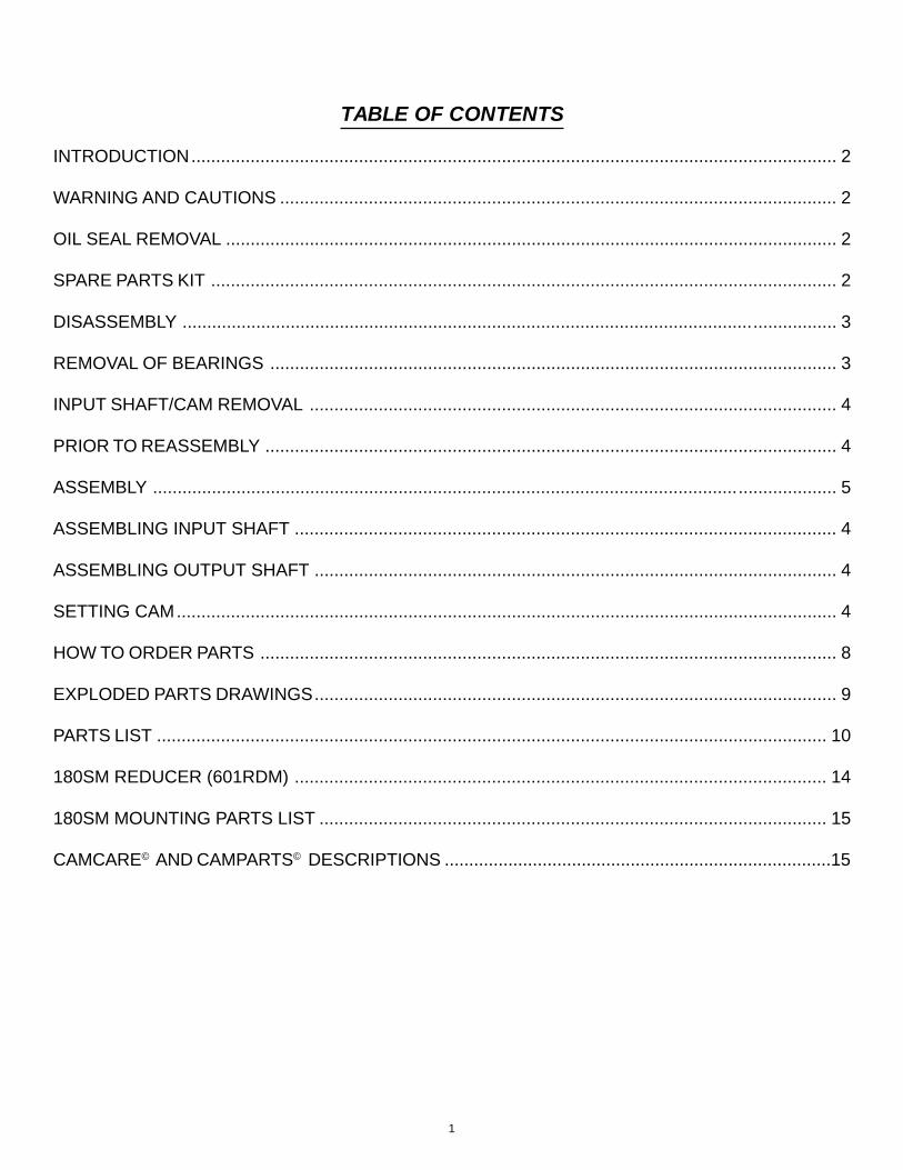
TABLE OF CONTENTS
INTRODUCTION................................................................................................................................... 2
WARNING AND CAUTIONS ................................................................................................................. 2
OIL SEAL REMOVAL ............................................................................................................................ 2
SPARE PARTS KIT ............................................................................................................................... 2
DISASSEMBLY .................................................................................................................... ................. 3
REMOVAL OF BEARINGS ................................................................................................................... 3
INPUT SHAFT/CAM REMOVAL ........................................................................................................... 4
PRIOR TO REASSEMBLY .................................................................................................................... 4
ASSEMBLY ....................................................................................................................... .................... 5
ASSEMBLING INPUT SHAFT .............................................................................................................. 4
ASSEMBLING OUTPUT SHAFT .......................................................................................................... 4
SETTING CAM...................................................................................................................................... 4
HOW TO ORDER PARTS ..................................................................................................................... 8
EXPLODED PARTS DRAWINGS.......................................................................................................... 9
PARTS LIST ........................................................................................................................................ 10
180SM REDUCER (601RDM) ............................................................................................................ 14
180SM MOUNTING PARTS LIST ....................................................................................................... 15
CAMCARE© AND CAMPARTS© DESCRIPTIONS ...............................................................................15
1

INTRODUCTIONThis service manual pertains to the disassembly and assembly of CAMCO’s RDM Series Index Drives models80RDM, 601RDM, 902RDM, 1305RDM, & 1800RDM.
The manual is to be used in conjunction with the General Service Manual which describes the lubrication andgeneral maintenance of CAMCO Index Drives.
An exploded view of your specific Index Drive is included in this manual. Also included is a complete Bill ofMaterials for your convenience in identifying and ordering spare or replacement parts.
Some users of Index Drives have the facilities and trained personnel to accomplish service repair. You mustdetermine the extent to which intricate servicing should be done in your own facility. When in doubt, CAMCOrecommends that CAMCO trained servicemen make the repairs.
WARNINGS AND CAUTIONSStatements in this manual preceded by the words WARNING or CAUTION and printed in italics are veryimportant. We recommend you take special notice of these during service or repair.
WARNINGMeans there is the possibility of personal injury to yourself or others.
CAUTIONMeans there is the possibility of damage to the CAMCO unit.
OIL SEAL REMOVALThe only repair possible without disassembly of the indexer is replacement of oil seals. To remove oil seals, drilla number of holes into the case of the seal. The seal may then be removed with a pointed tool. Be sure toremove all metallic chips created during the drilling of removal holes. A new seal may be installed as outlined inthe “Oil Seal Installation Recommendations” section of the “General Service Manual”.
SPARE PARTS KITCAMCO offers a Spare Parts Kit for all CAMCO index drive models CAMCO builds. These kits include oil seals,bearings, shims and miscellaneous haqrdware. Camfollowers are sold seperately. These are components thatwill most likely require replacement during repair of your index drive. CAMCO recommends a Spare Parts Kitbe purchased and kept on hand prior to the disassembly of your CAMCO drive.
A compete list of components supplied in the Spare Parts Kit can be found in the parts list located in the rear ofthis manual. The asterisk behind the item number indicates those parts supplied with the Spare Parts Kit.See page 16 for additional spare parts information.
BEFORE STARTINGBefore starting the disassembly of your CAMCO unit you should read and review the following instructions.These provide important information on parts and procedures necessary to successfully complete your repair.
Comply with all Warnings and Cautions.
Read the “Trouble Shooting Guide” section of your “General Service Manual” before disassembling CAMCOunits. CAMCO recommends returning defective equipment for inspection and repair whenever possible.
CAMCO uses Loc-Tite to secure all screws and setscrews, If you encounter a fastener that is difficult toremove, apply heat to the screw and remove while still warm.
2

DISASSEMBLY1. REMOVE ALL ACCESSORY EQUIPMENT such
as clutches, reducers, sprockets, etc. If equippedwith a CAMCO R250 Reducer see disassemblyinstructions manual 0079 pertaining to thisreducer prior to removal from the unit.
2. DRAIN OIL AND FLUSH UNIT with flushingsolvent. Retain any chips or broken pieces youmay find. These may aid in diagnosis.
3. REMOVE BOTTOM COVER.
4. REMOVAL OF OUTPUT SHAFT.
A. Remove the capscrews holding the largeoutput bearing retaining ring.
B. Drive the two dowel pins through theretaining ring and housing with an undersizepunch.
C. Lift the output/follower wheel from thehousing. Save the retaining ring shims forlater installation.
Fig.1 Output shaft removal
5. FOLLOWER INSPECTION.
Inspect followers for damage or radial looseness. Itshould not exceed .001 inch. Do not confuse radiallooseness with axial endplay. Endplay will be from.03” to .06” as a normal condition. If it exceeds .06it may require replacement.
NOTE: Generally, followers are replaced as addedinsurance against failure later.
Fig.2 Inspecting for radial looseness
6. FOLLOWER REMOVAL.
Followers can be removed at this stage.
A. Remove the setscrews. Apply heat to thesetscrews holding the follower studs andremove while still warm.
B. Threaded holes have been provided in theends of the follower for ease of removal.Use a slide hammer or a simple self-madepull tool. The self-made pull tool consists ofa short piece of round tubing, large enoughto clear the follower diameter and a smallflat bar with a clearance hole large enoughto insert a capscrew of equal thread size asthe follower pull hole. Slip the tube over thefollower, place the bar over the tube andthread a capscrew into the follower.Tightening the capscrew will remove thefollower.
Fig.3 Follower pull tools.
3

Fig.3A Follower pull tools in use.
7. CHECK THE FOLLOWER HOLES.
Check the follower holes for roundness.Theseholes may be worn out due to overloads. Theholes should be round to within .0005 to permitreuse of the follower wheel.
8. OUTPUT SHAFT DISASSEMBLY.
A. Turn output shaft over and tap on back sideof retaining ring, alternating from side toside until the retaining ring is free of theoutput/follower wheel.
B. Remove the main bearing from the output/follower wheel.
1) Remove the bearing retaining capscrewsand washers.
2) From the top side of the output, place asmall aluminum bar against the inside faceof the bearing and tap with a hammer.Alternate from side to side to preventcocking until the bearing is free of theoutput/follower wheel.
Fig .4. Removing output bearing.
9. INPUT SHAFT / CAM REMOVAL.
NOTE: The output shaft must be removed priorto input shaft removal.
A. Rotate the input shaft and inspect all partsfor damage or wear. Endplay in the inputshaft is not permissible.
B. Remove all input bearing cartridgecapscrews.
C. Tap on the end of the input shaft to drive theopposite cartridge from the housing. Thendrive the shaft in the opposite direction forremoval of the other cartridge.
NOTE: Keep shims with their respectivecartridges. You will be asked to reinstall orreplace with the same shim thickness duringassembly.
D. Remove the input shaft/cam assembly fromthe housing.
Fig. 5 Removing input shaft assembly
4

E. Use a wheel puller to remove the bearingcones from the input shaft.
F. Remove the cam locknuts with a spannerwrench. Be sure to bend the washer lockingtangs away from the nut prior to removal, ifapplicable.
G. Use an arbor press to remove the cam fromthe input shaft. Use caution not to damagethe parts. If an arbor press is not availableyou may drive the shaft out by tapping onthe end of the shaft with a soft face.
hammer.
Fig. 6 Pressing out camshaft
10. REMOVE THE INPUT BEARING CUPS
Remove the input bearing cups from thecartridges with a pulley puller, by prying orby drilling and tapping for jack screws.
ASSEMBLY
PRIOR TO REASSEMBLYClean and deburr all parts before reassembly.
Follow tightening torque and Loc-Titerecommendations as outlined in the “GeneralService Manual”.
1. Use an arbor to press the bearing cups into thecartridges. Coat the outside of the cup and thebore of the cartridge with an anti-seize lubricantprior to pressing. Fill cavity of cartridges withbearing grease recommended in the “GeneralService Manual”.
2. ASSEMBLING INPUT SHAFT.
A. Use arbor to press the cam onto the shaft.Be sure key is installed into the shaft first.Apply anti-sieze lubricant to shaft and boreprior to pressing. If a heat gun is available itis recommended that the bore of the cam beheated prior to pressing.
B. Use a spanner wrench to install the camlocknuts. Adjust nuts to center cam onshaft.
Fig.7. Centering cam on shaft
C. Use an arbor to press bearing cones ontoshaft. Coat shaft and bearing bore with anti-sieze lubricant prior to pressing. If a heatgun is available it is recommended that thebore of the bearing be heated prior topressing.
D. Install the input cartridges. Be sure to installthe same exact shims or equivalent heightas was removed in disassembly Step 9C.
E. Tighten cartridge mounting screws.
F. If endplay exists remove an equal amount ofshims from each side until there is a smallamount of drag from preloading thebearings. In rare instances it may benecessary to re-machine the cartridges if allshims have been removed and endplay stillexists.
3. ASSEMBLING OUTPUT SHAFT.
A. Install the large bearing cones on the outputshaft. Coat the bore of the cone with an anti-sieze lubricant prior to installation. Tap inplace with a hammer and aluminum bar.Place the bar against the inner face and tapwith hammer. Alternate from side to side toavoid binding until the bearing is fully seatedon the output/follower wheel.
5

B. Install the bearing retainer capscrews andwashers. Use torque and Loc-Titerecommendations from the “GeneralService Manual”.
C. Install new followers with an arbor press.
CAUTION: Be sure to press the followers in straightas damage to the follower and wheel could occur ifimproperly aligned during installation. Be sure thatthe notches are aligned with the setscrew holes.
Fig. 8 Pressing in new followers
D. Install the setscrews with double-notchfollowers, the cone point setscrews lock intothe “V” notch. The cup point setscrews lockagainst the flat single-notch followers, usean oval point setscrew. Be sure to use Loc-tite thread locking liquid as recommended inthe “General Service Manual”.
E. Coat the inside of the bearing retainer ringand the outside of the main output bearingwith anti-sieze lubricant. Place the bearingretainer ring over the output from thetopside of the output/follower wheel and tap,alternating from side to side until theretainer is fully seated on the bearing.
F. Replace the shims removed in disassemblystep 4C.
G. Place cam in dwell position, keyway pointingrearward.
H. Insert output/follower wheel into housingwith dowel holes in housing in line withretainer.
I. Loosely install the bearing retainercapscrews.
J. Install only one of the dowel pins through theretainer ring into the housing.
4. SETTING THE CAM.
CAUTION: This mechanism is designed to operatewith adjacent followers in close contact along theirentire width, unless this condition is achieved byproper installation, the mechanism will not transmitits rated load,and serious damage to the cam andoutput shaft will occur.
A. Place the unit on end or its side so both theoutput side and the bottom opening areaccessible.
B. Place the cam in dwell, keyway facingrearward.
C. While pivoting on the one dowel pin, rotatethe output towards the input shaft as muchas the clearance holes for the mountingcapscrews will allow.
D. Shift the cam axially until two adjacentfollowers are in full contact with the cam rib.This will also require adjustment of theoutput retaining ring along with axialadjustment of the cam.
1) If there is a gap at the root of thefollower the cam should be shiftedtoward the follower.
2) If there is a gap at the tip of the followerthe cam should be shifted away from thefollower.
Fig.9 Shifting cam for proper alignment
6

E. Apply “Prussian Blue” to entire cam track.
F. Rotate the camshaft slowly with a smallhandcrank to ensure that:
1) Both rollers are in contact with the camrib in dwell. Look for uniform blueingpattern.
2) The follower is free when it is in thecenter of the crossover track.
3) You do not encounter unusualresistance in motion. The bluing patternshould be fairly uniform from side to sideduring motion. If a patch of bluing isworn off the outside of the cam rib onone side of the cam and not the other,shift the cam a .002 to .005 inches in thedirection of the worn side. Do notovershift the cam or knocking will occur.
4) The cam bluing should never be wornoff the lead-in or exit edges of the camribs. This would indicate that the cam isnot adjusted properly.
5) There should be no looseness in anydwell. If there is looseness adjust theoutput bearing retainer to slightlypreload the loosest dwell.
G. Tighten the locknuts and secure with
Loc-Tite #242 as specified in the “GeneralService Manual”. If lockwashers are used onyour model, bend the tangs over the nut toinsure locking.
Figure 10 Tighten cam locknuts
H. Tighten the output retaining ring capscrews.
I. Drill and ream the remaining hole in theoutput retaining ring to accept the nextlarger dowel pin. Install new dowel.
8. REINSTALL THE BOTTOM COVER. Apply“General Electric Silicone Rubber RTV-6” to thesealing surfaces of the housing and cover. Placethe gasket on the housing and place cover overthe gasket. Install and tighten capscrews.
9. GREASE PACK THE MAIN OUTPUT BEARINGwith lubricant specified in the “General ServiceManual”.
10. INSTALL NEW OIL SEALS as described inthe “General Service Manual”.
11. FILL THE INDEX WITH THERECOMMENDED OIL to level indicator. See“General Service Manual”. Too high an oil levelwill cause no damage. Too low a level may resultin unit failure.
7

HOW TO ORDER PARTS
Please refer to parts list shown in this manual. This parts list is for a standard Index Drive. If you feel your driveis nonstandard or you are in doubt you should contact CAMCO Customer Service at (847) 459-5200 andrequest a Bill of Materials for your specific unit based on serial number. CAMCO maintains records on all unitsfor a period of ten years.
You may order parts per the standard Bill of Material even if your unit is nonstandard. CAMCO’s order entrydepartment will review the closed order file based on the following information and supply you with the correctpart.
REQUIRED INFORMATION1. Original purchase order number (if available)
2. Customer name (original purchaser of drive)
3. Model number (located on name plate)
4. Serial number (located on name plate)
5. Approximate date of purchase.
TO ORDER PARTS contact CAMCO “Order Entry Department” Wheeling, Illinois
Phone (847) 459-5200 or Fax (847) 459-3064
A. Describe the parts required and the 14 digit part number as listed in the Standard Bill of Materials or aSpecial Bill of Materials pertaining to your unit. State if you are using a Standard or Specific bill ofmaterial.
B. Give as much of the above required information as possible.
ON WARRANTYCAMCO will send replacement parts freight prepaid via most practical mean.
CAMCO will issue a “Returned Material Authorization Number” (RMA#) for the return of defective parts forinspection. CAMCO will bill customer for repair parts. When inspection of returned parts has been completedand determined to be covered under warranty, CAMCO will issue a credit to the customer for the repair partsand freight charges. Camco standard warranty is defined in Camco’s “Terms and Conditions”.
ON NON-WARRANTY
Replacement or spare parts, with approved credit, are F.O.B. our plant Wheeling, Illinois.
8

601RDM, 902RDM, 1305RDM & 1800RDM
9
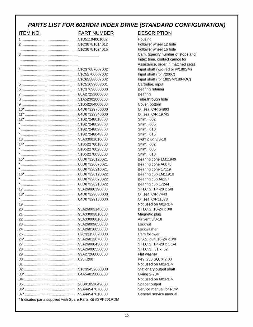
PARTS LIST FOR 601RDM INDEX DRIVE (STANDARD CONFIGURATION)ITEM NO. PART NUMBER DESCRIPTION1 ...................................................... 51D51194001002 Housing2 ...................................................... 51C38781014012 Follower wheel 12 hole........................................................ 51C38781024016 Follower wheel 16 hole
3 ...................................................... __________ Cam, (specify number of stops and........................................................ Index time, contact camco for........................................................ Assistance, order in matched sets)
4 ...................................................... 51C37687007002 Input shaft (w/o red or w/180SM)........................................................ 51C52700007002 Input shaft (for 7200C)........................................................ 51C65588007002 Input shaft (for 180SM/180-IOC)
5 ...................................................... 51C51099003001 Cartridge, input6 ...................................................... 51C37690000000 Bearing retainer7 ...................................................... 86A27251000000 Bearing8 ...................................................... 51A52302000000 Tube,through hole9 ...................................................... 51B52264000000 Cover, bottom10* ................................................... 84D07329780000 Oil seal C/R 6499311* ................................................... 84D07329340000 Oil seal C/R 1974512* ................................................... 51B27248018800 Shim, .002* ....................................................... 51B27248028800 Shim, .005* ....................................................... 51B27248038800 Shim, .010* ....................................................... 51B27248048800 Shim, .01513 .................................................... 95A33001010000 Sight plug 3/8-1814* ................................................... 51B52278018800 Shim, .002* ....................................................... 51B52278028800 Shim, .005* ....................................................... 51B52278038800 Shim, .01015* ................................................... 86D07328120021 Bearing cone LM11949* ....................................................... 86D07328070021 Bearing cone A6075* ....................................................... 86D07328210021 Bearing cone 1711916* ................................................... 86D07328120022 Bearing cup LM11910* ....................................................... 86D07328070022 Bearing cup A6157* ....................................................... 86D07328210022 Bearing cup 1724417 .................................................... 95A26000390000 S.H.C.S. 1/4-20 x 5/818* ................................................... 84D07329080000 Oil seal C/R 7443* ....................................................... 84D07329180000 Oil seal C/R1187819 .................................................... __________ Not used on 601RDM20 .................................................... 95A26003140000 B.H.C.S. 10-24 x 3/821 .................................................... 95A33003010000 Magnetic plug22 .................................................... 95A33000010000 Air vent 3/8-1823 .................................................... 95A26009050000 Locknut24 .................................................... 95A26010050000 Lockwasher25 .................................................... 82C33150020003 Cam follower26* ................................................... 95A26012070000 S.S.S. oval 10-24 x 3/827 .................................................... 95A26000430000 S.H.C.S. 1/4-20 x 1 1/428 .................................................... 95A26000530000 S.H.C.S. .31 x .6229 .................................................... 99A27266000000 Flat washer30 .................................................... 025K200 Key .250 SQ. X 2.0031 .................................................... __________ Not used on 601RDM32 .................................................... 51C39452000000 Stationary output shaft33* ................................................... 84A54015000000 O-ring 2-23434 .................................................... __________ Not used on 601RDM35 .................................................... 26B01051049000 Spacer output36* ................................................... 99A44547070000 Service manual for RDM37* ................................................... 99A44547010000 General service manual* Indicates parts supplied with Spare Parts Kit #SPK601RDM
10

PARTS LIST FOR 902 RDM INDEX DRIVE (STANDARD CONFIGURATION)ITEM NO. PART NUMBER DESCRIPTION1 ............................................................. 56D59101001002 Housing Standard............................................................... 56C44335001002 Housing W/ Center Post/Tooling............................................................... 56D41866001002 Housing W/Pl Mounting Holes............................................................... 56C38728001002 Housing W/Stationary Center Post2 ............................................................. 56C38768014012 Follower Wheel 12 Hole H32............................................................... 56C38768024016 Follower Wheel 16 Hole H323 ............................................................. __________ Cam, (Specify Number Of Stops And............................................................... Index Time, Contact Camco For............................................................... Assistance, Order In Matched Sets)4 ............................................................. 56C38713007002 Input Shaft (No Reducer)............................................................... 83D36422007002 Input Shaft (For R250)............................................................... 56C39230007002 Input Shaft (For 25GED)............................................................... 56C63374007002 Input Shaft (For R225)............................................................... 56D63506007002 Input Shaft (For R225 W/IOC)............................................................... 56C51857007002 Input Shaft (For R260)............................................................... 56D61647007002 Input Shaft (For R260 W/ 20 DHL)............................................................... 83D47856007002 Input Shaft (For R250 Dual C/L)5 ............................................................. 56C36428003021 Cartridge Open (Inp)6 ............................................................. 56C23495009300 Retainer Bearing7 ............................................................. 86A24320000000 Bearing8 ............................................................. __________ Not Used On 902RDM9 ............................................................. 56B35134009600 Cover, Bottom10* .......................................................... 84D07329860000 Oil Seal C/R 9505211* .......................................................... 84D07329500000 Oil Seal C/R 2728012* .......................................................... 56B26168018800 Shim, .002* .............................................................. 56B26168028800 Shim, .005* .............................................................. 56B26168038800 Shim, .01013 ........................................................... 95A33001010000 Sight Plug 3/8-1814* .......................................................... 56C36423018800 Shim, .002* .............................................................. 56C36423028800 Shim, .005* .............................................................. 50B06038028800 Shim, .005* .............................................................. 56C36423038800 Shim, .01015* .......................................................... 86A22882000021 Bearing Cone Lm6704916* .......................................................... 86A22882000022 Bearing Cup Lm6701017 ........................................................... 95A26000390000 S.H.C.S. 1/4-20 X 5/818 ........................................................... 84D07329180000 Oil Seal C/R1187819 ........................................................... __________ Not Used On 902RDM20 ........................................................... 95A26015220000 H.H.C.S. 10-24 X 1/221 ........................................................... 95A33003010000 Magnetic Plug22 ........................................................... 95A33000010000 Air Vent 3/8-1823 ........................................................... 95A26009070000 Locknut............................................................... 95A26009080000 Locknut24 ........................................................... __________ Not Used On 902RDM25 ........................................................... 82C33150040003 Cam Follower26* .......................................................... 95A26012130000 S.S.S. Oval Pt 1/4-20 X 3/827 ........................................................... 95A26000580000 S.H.C.S. 5/16-18 X 1 1/228 ........................................................... 95A26016450000 S.H.C.S. 3/8-24 X 3/429 ........................................................... 99A24322000000 Heavy Duty Flat Washer30 ........................................................... 031K300 Key .3125 Sq. X 331 ........................................................... 95A33033170000 Retaining Ring 5160-12532 ........................................................... 56L26076009540 Stationary Output Shaft............................................................... 56C58129009540 Stationary Output Shaft For 10.50 Mounting33* .......................................................... 99A26350000000 O Ring Parker #236* .............................................................. 84A56357000000 O-Ring 2-155 Buna N* .............................................................. 84A36425000000 O-Ring Parker #-13634 ........................................................... 56C63181009100 Mounting Plate (For R225)............................................................... 56D36427003021 Mounting Plate (For R250)............................................................... 80C39416009100 Mounting Plate (For Red)............................................................... 80C51855000000 Mounting Plate (For R260)35 ........................................................... __________ Not Used On 902 RDM36* .......................................................... 99A44547070000 Service Manual-RDM37* .......................................................... 99A44547010000 General Service Manual* Indicates parts supplied with Spare Parts Kit #SPK901RDM
11
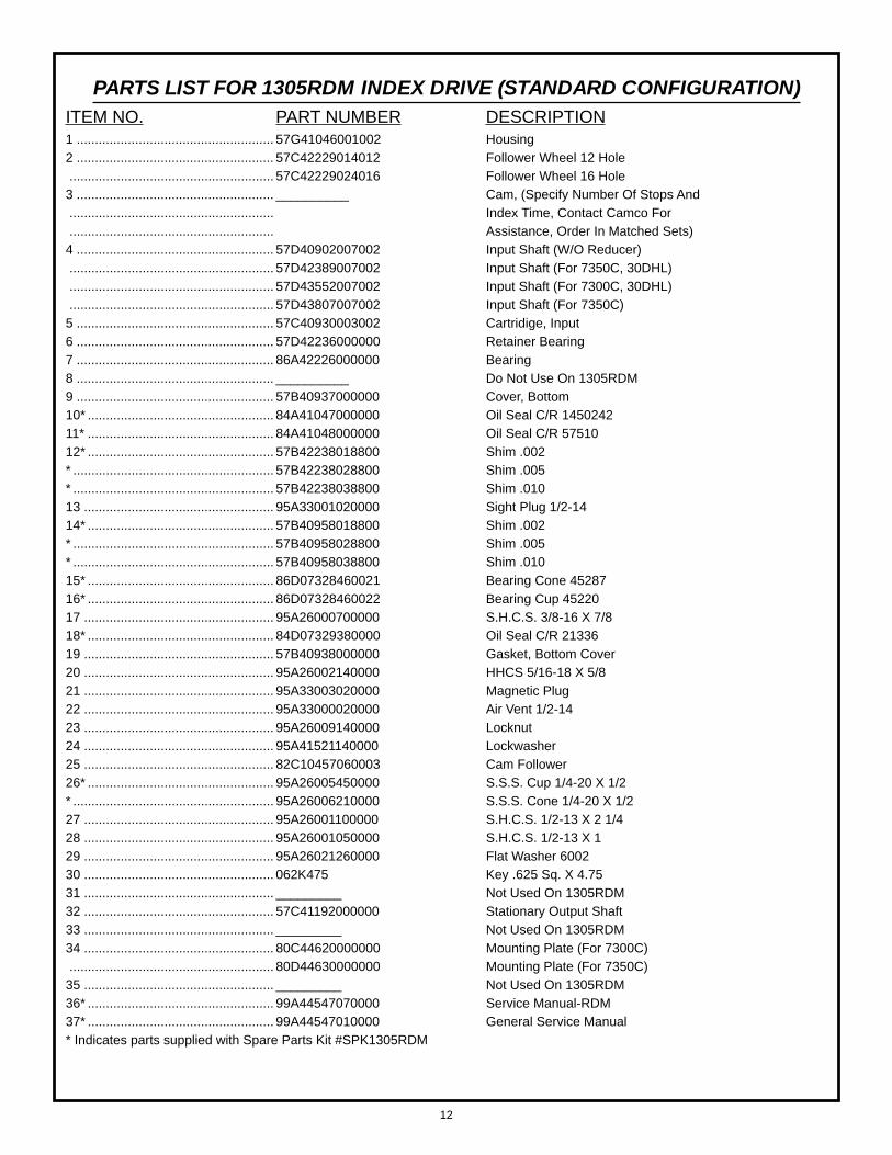
PARTS LIST FOR 1305RDM INDEX DRIVE (STANDARD CONFIGURATION)ITEM NO. PART NUMBER DESCRIPTION1 ...................................................... 57G41046001002 Housing2 ...................................................... 57C42229014012 Follower Wheel 12 Hole........................................................ 57C42229024016 Follower Wheel 16 Hole
3 ...................................................... __________ Cam, (Specify Number Of Stops And........................................................ Index Time, Contact Camco For........................................................ Assistance, Order In Matched Sets)
4 ...................................................... 57D40902007002 Input Shaft (W/O Reducer)........................................................ 57D42389007002 Input Shaft (For 7350C, 30DHL)........................................................ 57D43552007002 Input Shaft (For 7300C, 30DHL)........................................................ 57D43807007002 Input Shaft (For 7350C)
5 ...................................................... 57C40930003002 Cartridige, Input6 ...................................................... 57D42236000000 Retainer Bearing7 ...................................................... 86A42226000000 Bearing8 ...................................................... __________ Do Not Use On 1305RDM9 ...................................................... 57B40937000000 Cover, Bottom10* ................................................... 84A41047000000 Oil Seal C/R 145024211* ................................................... 84A41048000000 Oil Seal C/R 5751012* ................................................... 57B42238018800 Shim .002* ....................................................... 57B42238028800 Shim .005* ....................................................... 57B42238038800 Shim .01013 .................................................... 95A33001020000 Sight Plug 1/2-1414* ................................................... 57B40958018800 Shim .002* ....................................................... 57B40958028800 Shim .005* ....................................................... 57B40958038800 Shim .01015* ................................................... 86D07328460021 Bearing Cone 4528716* ................................................... 86D07328460022 Bearing Cup 4522017 .................................................... 95A26000700000 S.H.C.S. 3/8-16 X 7/818* ................................................... 84D07329380000 Oil Seal C/R 2133619 .................................................... 57B40938000000 Gasket, Bottom Cover20 .................................................... 95A26002140000 HHCS 5/16-18 X 5/821 .................................................... 95A33003020000 Magnetic Plug22 .................................................... 95A33000020000 Air Vent 1/2-1423 .................................................... 95A26009140000 Locknut24 .................................................... 95A41521140000 Lockwasher25 .................................................... 82C10457060003 Cam Follower26* ................................................... 95A26005450000 S.S.S. Cup 1/4-20 X 1/2* ....................................................... 95A26006210000 S.S.S. Cone 1/4-20 X 1/227 .................................................... 95A26001100000 S.H.C.S. 1/2-13 X 2 1/428 .................................................... 95A26001050000 S.H.C.S. 1/2-13 X 129 .................................................... 95A26021260000 Flat Washer 600230 .................................................... 062K475 Key .625 Sq. X 4.7531 .................................................... _________ Not Used On 1305RDM32 .................................................... 57C41192000000 Stationary Output Shaft33 .................................................... _________ Not Used On 1305RDM34 .................................................... 80C44620000000 Mounting Plate (For 7300C)........................................................ 80D44630000000 Mounting Plate (For 7350C)
35 .................................................... _________ Not Used On 1305RDM36* ................................................... 99A44547070000 Service Manual-RDM37* ................................................... 99A44547010000 General Service Manual* Indicates parts supplied with Spare Parts Kit #SPK1305RDM
12

PARTS LIST FOR 1800RDM INDEX DRIVE (STANDARD CONFIGURATION)ITEM NO. PART NUMBER DESCRIPTION1 ...................................................... H2G48562001002 Housing
2 ...................................................... H2D48544014012 Follower Wheel 12 Hole
........................................................ H2D48544024016 Follower Wheel 16 Hole
3 ...................................................... __________ Cam, (Specify Number Of Stops And
........................................................ Index Time, Contact Camco For
........................................................ Assistance, Order In Matched Sets)
4 ...................................................... H2D48524007002 Input Shaft (W/O Red)
........................................................ H2D48525007002 Input (Shaft For 7400C)
........................................................ H2D48731007002 Input Shaft (For 7500C)
........................................................ H2D50672007002 Input Shaft (For 7400C/400-IOC)
........................................................ H2D55014007002 Input Shaft (For 7500C/500-IOC)
5 ...................................................... H2C64443003002 Cartridge Input
6 ...................................................... H2D64003000000 Bearing Retainer
8 ...................................................... _____________ Not Used On 1800RDM
9 ...................................................... 56B35134009600 Cover Bottom
10* ................................................... 84A48576000000 Oil Seal 2050252
11* ................................................... 84A48577000000 Oil Seal 75030
12* ................................................... H2B48578018800 Shim, .002
* ....................................................... H2B48578028800 Shim, .005
* ....................................................... H2B48578038800 Shim, .010
13 .................................................... 95A33001030000 Sight Plug 3/4-14
14* ................................................... H2B48579018800 Shim, .002
* ....................................................... H2B48579028800 Shim, .005
* ....................................................... H2B48579038800 Shim, .010
15* ................................................... 86D07328600021 Bearing Cone 566
16* ................................................... 86D07328600022 Bearing Cup 563
17 .................................................... 95A26000710000 S.H.C.S. 3/8-16 X1
18* ................................................... 84D07329510000 Oil Seal C/R 27295
19 .................................................... H2C48539000000 Gasket, Cover 1800RDM
20 .................................................... 95A26003140000 B.H.C.S. 10-24 X 3/8
21 .................................................... 95A33003060000 Magnetic Plug
22 .................................................... 95A33000030000 Air Vent 3/4-14
23 .................................................... 95A26009160000 Locknut Pn-16
24 .................................................... 95A41521160000 Lockwasher Wh-16
25 .................................................... 82C10457080003 Cam Follower Cfh 292
26* ................................................... 95A26005470000 S.S.S. Cup Pt 1/4-20 X 3/4
27 .................................................... 95A26001300000 S.H.C.S. 5/8-11 X 2 1/2
28 .................................................... 95A26001260000 S.H.C.S..5/8-11 X 1 1/2
29 .................................................... 95A26021270000 Washer Flat 6003
30 .................................................... 075K650 Key .750 Sq X 6.50 Lg
31 .................................................... H2D64002000000 Retaining Ring, 1800RDM Mach
32 .................................................... H2C48734000000 Stationary Output Shaft
33 .................................................... _________ Not Used On 1800RDM
34 .................................................... 80D48720000000 Mounting Plate (For 7400C)
........................................................ 80C48730009100 Mounting Plate (For 7500C)
35 .................................................... _____________ Not Used On 1800RDM
36* ................................................... 99A44547070000 Service Manual-RDM
37* ................................................... 99A44547010000 General Service Manual
* Indicates parts supplied with Spare Parts Kit #SPK1800RDM
13

180SM REDUCER
14

PARTS LIST FOR 180SM REDUCER MOUNTING TO 601RDMITEM NO. PART NUMBER DESCRIPTION1 ...................................................... 89A39466050000 Reducer 5:1 Ratio
........................................................ 89A39466070000 Reducer 7.5:1 Ratio
........................................................ 89A39466100000 Reducer 10:1 Ratio
........................................................ 89A39466150000 Reducer 15:1 Ratio
........................................................ 89A39466200000 Reducer 20:1 Ratio
........................................................ 89A39466250000 Reducer 25:1 Ratio
........................................................ 89A39466300000 Reducer 30:1 Ratio
........................................................ 89A39466400000 Reducer 40:1 Ratio
........................................................ 89A39466500000 Reducer 50:1 Ratio
........................................................ 89A39466600000 Reducer 60:1 Ratio
0065 RDM .......................................
2 ...................................................... 80C39246009100 Reducer Mounting Plate
3 ...................................................... 95A26000420000 SHCS 1/4-20 X 1
4 ...................................................... 95A26002030000 SHCS 1/4-20 X 3/4
5 ...................................................... M06K187 KEY 6MM SQ. X 1 7/8 LG
6 ...................................................... 99A38233000000 HAND KNOB
80RDM ............................................
2 ...................................................... 89B67859009100 Reducer Mounting Plate
3 ...................................................... 95A33040170000 SHCS M6 X 12
4 ...................................................... 95A33040180001 SHCS M6 X 16
5 ...................................................... 99A38233000000 KEY 6MM SQ. X 2.75 LG
6 ...................................................... 99A38233000000 HAND KNOB
SPARE PARTS KITSMODEL ITEM PART NUMBER80RDM ...................................... Kit .............................................. SPK80RDM
601RDM .................................... Kit .............................................. SPK601RDM
902RDM .................................... Kit .............................................. SPK902RDM
1305RDM .................................. Kit .............................................. SPK1305RDM
1800RDM .................................. Kit .............................................. SPK1800RDM
15

99 A44547 07 0000 USA 6/99 0065