Service Manual Pump Models: VX Series Q Pumps
77
Service Manual Service Manual Pump Models: VX Series Q Pumps Level 1 Service Manual for all VX Q Series Pumps Prior to starting any repair, make sure you understand the safety instructions provided with any piece of rotating equipment. There is a specific section in this manual that deals with safety concerns related to the Vogelsang Pump. Make sure you read and understand this section completely prior to starting any repair. If you have questions, please contact: 800.984.9400
Transcript of Service Manual Pump Models: VX Series Q Pumps

Service Manual Service Manual Pump Models: VX Series Q Pumps
Level 1 Service Manual for all VX Q Series Pumps
Prior to starting any repair, make sure you understand the safety instructions provided with any piece of rotating equipment. There is a specific section in this manual that deals with safety concerns related to the Vogelsang Pump. Make sure you read and understand this section completely prior to starting any repair. If you have questions, please contact: 800.984.9400

Service Manual Service Manual Pump Models: VX Series Q Pumps
Section 1: General Information for Operation & Maintenance General Instructions
Description of the Vogelsang Positive Displacement Rotary Lobe Pump and how it functions
The Vogelsang positive displacement rotary lobe pump employs right and left set lobes, top and bottom, rotating in opposite directions, driven by an external power source, to move fluid from the suction side of the pump to the discharge side.
During operation the lobes mesh together, forming cavities between the rotors and the casing. The lobes mesh tightly together in the center of the pump and have a very small clearance at the radial housing. As the lobes continue to turn, the fluid and objects are moved along the outer perimeter of the pump. As the pump completes a full cycle, the fluid is pumped through to the discharge side of the pump. The direction of flow is determined by the rotation of the lobes. Vogelsang positive displacement rotary lobe pumps can operate in both forward and reverse directions of flow.
If you are in doubt about the functionality of your Vogelsang product, please ask us. Any other use is contrary to the intended purpose. The manufacturer is not liable for damages or wear caused by incorrect use.

Service Manual Service Manual Pump Models: VX Series Q Pumps
Identification
Each Vogelsang pump is tagged with an identification label on the gearbox end of the pump. This tag shows the full model designation, serial number, year of manufacture and maximum operating conditions, if applicable. Refer to the illustrations below.

Service Manual Service ManualPump Models:VX Series Q Pumps
Normal Operation Information
Pre-startupchecks
StartupNormal
OperationShutdown
EmergencyShutdown
Properly install and pressurize buffer chamberusing the pressurized oil bottle. Follow
instructions outlined in this document.X X X
For direct drive assemblies: Confirm the pumpand drive unit are properly coupled and aligned.Coupler guard must be in place.
X X X
For belt drive assemblies: Confirm sheaves arealigned and belt is properly tensioned. Beltguard must be in place.
X X X
Confirm that ALL base plate mounting points arefastened and properly tightened. X X X
Confirm that there are no obstructions in thepipelines. X X X
Pressure relief system, valves, etc, must be ingood working order and set to the appropriaterelief pressure.
X X X
Under no circumstances should the pump orits flanges, be used to support external loads.All piping must be supported.
X X X
Pump should be filled with liquid before initialstartup and any restart. X X
Liquid should be drained from the wet-end ofthe pump, to insure it does not freeze, orset-up in the wet-end.
X
Insure the surrounding piping matches orexceeds the port size of the pump, to reducethe chance of cavitation.
X X X
Confirm the NPSHA in the system is suitablefor the NPSHA of the pump, to ensure smoothoperation of the pump, without cavitation
X X X
Insure suction and discharge gauges areproperly installed, and working. X X X
Insure all PM has been completed on the pumpand drive system. X X

Service Manual Service Manual Pump Models: VX Series Q Pumps
Pre-startup
checks Startup Normal Operation Shutdown Emergency
Shutdown
Rotate the pump one complete turn each month, to insure proper lubrication of mechanical seals.
X X X X
Clean wet-end of unit to insure a smooth re-start.
X X X

Service Manual Service Manual Pump Models: VX Series Q Pumps

Service Manual Service Manual Pump Models: VX Series Q Pumps

Service Manual Service Manual Pump Models: VX Series Q Pumps

Service Manual Service Manual Pump Models: VX Series Q Pumps
Sequence of Operations
1 Open all suction and discharge valves
2 Assure completion of all startup checks in table above
3 Assure compliance with any electrical checklist for this application
4 Engage pump
5 Assure normal operation parameters
6 Upon shutdown, observe shutdown advisories in chart above

Service Manual Service Manual Pump Models: VX Series Q Pumps
Installation, Maintenance, Calibration & Repair Installation
Vogelsang does not install equipment supplied as this is the responsibility of the contractor. See section 2.A.1 for installation advice. However, when designing your system, keep in mind the below guidelines.
When designing the pumping system:
DO - Confirm with the supplier the Net Positive Suction Head (NPSH) requirements for the pump, as this is crucial for ensuring the smooth operation and preventing cavitation.
DO - Avoid suction lifts and manifold/common suction lines for two pumps running in parallel, as this may cause vibration or cavitation.
DO - Protect the pump against blockage from incompressible solid objects e.g. nuts, bolts etc. Also protect the pump from accidental operation against a closed valve by using one or all of the following methods: relief valves, pressure switch, current monitoring device.
DO - Fit suction and discharge pressure gauges to monitor pressures for diagnostic purposes.
Depending on your requirements, the pump and drive (if supplied) may arrive mounted on a baseplate. Our standard baseplates have pre-drilled mounting holes to accept base retaining bolts. All mounting holes are required for best results against vibration and noise.
To provide a permanent, rigid support for securing the pump unit, a foundation is required. This will also absorb vibration, and reduce strain on the pumping unit.
DO - Set appropriate pressure to the pump’s buffer chamber using the pressurized oil bottle that has been installed on your pump.
DO - Check alignments. Pump may become misaligned during shipping. For direct drive assemblies, make sure pump and motor are aligned and the coupling is making a straight connection. The coupling guard must be in place at all times during operation. For piggy-back belt driven assemblies, confirm that the sheaves are properly aligned and the belt is tensioned correctly. The belt guard must be in place at all times during operation.
DO - Make sure that all equipment and piping are properly supported. The pump assembly and flanges are only designed to support their own weight.

Service Manual Service Manual Pump Models: VX Series Q Pumps
Equipment Alignment – Base plate The base frame of motor driven units must not be out of alignment or under stress by the mounting bolts to prevent noise and wear of coupling. After mounting, the alignment of coupling must be checked and corrected prior to operation.
Retighten all motor and pump mounting screws on the frame after 20 initial operating hours. For pumps with belt drive check the belt tension as described earlier:
• After the first 10 operating hours • Then every 2000 operating hours
Use the eye bolts on the pumps only for lifting the pump without any additional mounting parts such as the motor.

Service Manual Service Manual Pump Models: VX Series Q Pumps
Trade Levels for installation
Consult with General Contractor as Vogelsang does not install equipment.
Special Rigging
Pump/Motor assemblies may exceed 3090 lbs. and so require some lifting device with chain and hooks to engage lifting eyes on pump and motor. Assemblies should never be lifted by pump alone, or by motor alone.
Special Test Equipment
No special test equipment is required for the installation of the pump assembly.

Service Manual Service Manual Pump Models: VX Series Q Pumps
Safety
Identify all safety and tag-out procedures Before setting into operation read and observe the contents of the operating instructions and the safety advisories. Warning and information stickers provide important information for safe operation. They may not be removed. Observation of these stickers provides for your safety.
Before start up of operations you should familiarise yourself with all facilities and operating options. Pump may only be set in operation if the suction and pressure pipes are connected so that access to the pumping chamber is not possible. Before pump is set in operation, ensure that access to the rotating parts (the drive shaft) is not possible.
The drive shaft must be completely covered by a coupling guard.
Before setting into operation, ensure that the discharge pipe is not completely closed off. Otherwise the pump shaft seals or even the pump housing or the pipelines may be damaged or destroyed by the resulting high pressure.
Before starting maintenance and repair work, turn off the drive and ensure that the pump cannot be switched on by mistake.
Use the eye bolts on the pumps only for lifting the pump without mounted parts (for example motor)!

Service Manual Service Manual Pump Models: VX Series Q Pumps
Lubrication
Lubrication Points & Lubrication Reservoirs
There is a buffer chamber on the VX Q pump that is filled with oil and pressurized using a pressurized oil bottle.
The gearbox is filled halfway with oil to lubricate the drive gears.

Service Manual Service Manual Pump Models: VX Series Q Pumps
2.C.3 Changing the Oil Change the Gear Oil:
• For the first time after a period of 20 operating hours. • Every 2000 operating hours.
Change the Buffer Chamber Oil:
• If Gear Oil has been changed. • Every 2000 operating hours, however not more than 3 months between fill ups. • See section 2.F.1 for information on using the pressurized oil bottle
Lubricant: Vogelsang Standard Oil Mineral Oil Titan Gear MP90, SAE 90, Combustion point: 215°C, Art-No. BSS.006
See the table of alternative oils on the following page.
1: Pressurized Oil Bottle A: Fill 2: Hex Head Screw Plug B: Empty 3: Magnetic Hex Head Screw Plug C: Check D: Pressurize
1 – A, C, D
2 – A
3 – B

Service Manual Service Manual Pump Models: VX Series Q Pumps
Lubrication Chart Lubrication Chart – VX Q Series Pumps
Location Lubrication Specification Supplier Product
Fuchs RENOLIN EP 220 Valvoline HP Gear Oil 80W-90 Quaker State FCIGL-5 MT-1 80W-90 BP Oil BP HYPO-U 80W-90 Titan Gear MP90 Gearplus
Gearbox MP90 Mineral Oil SAE 90-GC-5
Pennzoil 80W-90 GL-5
Fuchs RENOLIN EP 220 Valvoline HP Gear Oil 80W-90 Quaker State FCIGL-5 MT-1 80W-90 BP Oil BP HYPO-U 80W-90 Titan Gear MP90 Gearplus
Buffer Chamber
MP90 Mineral Oil SAE 90-GC-5
Pennzoil 80W-90 GL-5
Lubrication Quantity Chart – VX Q Series Pumps
Location Model Quantity
Buffer Chamber VX 136 Q Series 1.5 quarts / 1.5 liter
Gearbox VX 136 Q Series 2.1 quarts / 2 liter
Buffer Chamber VX 186 Q Series 2.5 quarts / 2.4 liter
Gearbox VX 186 Q Series 1 gallon / 4 liter

Service Manual Service Manual Pump Models: VX Series Q Pumps
Operational Startup & Testing Shown below is the standard we use to test each pump before it leaves the factory.

Service Manual Service Manual Pump Models: VX Series Q Pumps
Operational Startup & Testing (continued)

Service Manual Service Manual Pump Models: VX Series Q Pumps
Data from Startup & Testing Procedures
Actual certified field service reports will be inserted here, when conducted, and upon the final printing of this manual.
Test method, equipment, and procedure
Pump start-up is dependent on actual application. On start-up flow rates, pressures and speeds should be noted on the Start-Up checklist for comparison with design specifications. Differences should be noted.
Flow meters, pressure gauges and similar instruments may be used or installed in the system for observation of application conditions. Any request for technical assistance from Vogelsang will require this data.
Certified Factory tests will be conducted on all products per the specification, and approved by the engineer, prior to shipment.
Field tests will be conducted by the contractor per the specification. Vogelsang will witness these tests.

Service Manual Service Manual Pump Models: VX Series Q Pumps
Preventative Maintenance
Inspection & Routine Adjustment
S
tock
ed P
umps
: O
nce
Eve
ry 3
0 da
ys
Initi
al S
tartu
p
Bef
ore
& A
fter l
ong
ou
t-of-s
ervi
ce p
erio
ds
10 o
pera
ting
hour
s
afte
r ini
tial s
tartu
p
20 o
pera
ting
hour
s
afte
r ini
tial s
tartu
p
Eve
ry 2
00 o
pera
ting
hour
s
Eve
ry 5
00 o
pera
ting
hour
s or
3 m
onth
s
Eve
ry 2
000
oper
atin
g ho
urs
Afte
r Exp
osur
e to
stro
ng
cont
amin
atio
n
New Pump w/Mechanical Seal combination of metals: SiC-Si/TC. One Rotation when not in service
X
Remove plastic plug from breather on V100 QHD Pumps.
X
Check belt tension for belt drive pumps according to specification for all pumps configured with V-Belt Drives
X
X
Tighten all mounting bolts X
Check buffer chamber oil level
X X
Change buffer chamber oil X X
Change Gear Oil X X
Check Gear Oil Level X
Service Manual Service Manual Pump Models: VX Series Q Pumps
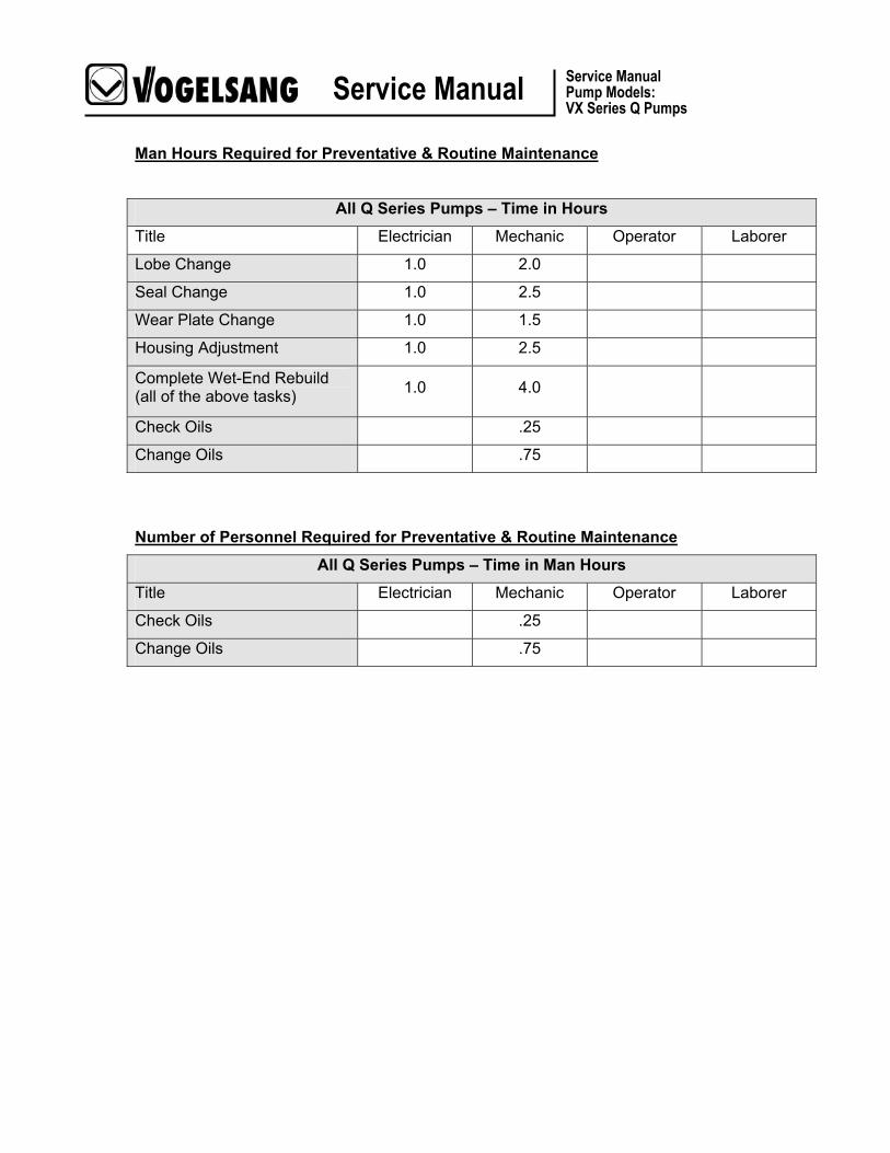
Man Hours Required for Preventative & Routine Maintenance
All Q Series Pumps – Time in Hours
Title Electrician Mechanic Operator Laborer
Lobe Change 1.0 2.0
Seal Change 1.0 2.5
Wear Plate Change 1.0 1.5
Housing Adjustment 1.0 2.5
Complete Wet-End Rebuild (all of the above tasks) 1.0 4.0
Check Oils .25
Change Oils .75
Number of Personnel Required for Preventative & Routine Maintenance
All Q Series Pumps – Time in Man Hours
Title Electrician Mechanic Operator Laborer
Check Oils .25
Change Oils .75

Service Manual Service Manual Pump Models: VX Series Q Pumps
Frequency of Preventative & Routine Maintenance
Sto
cked
Pum
ps:
Onc
e E
very
30
days
Initi
al S
tartu
p
Bef
ore
& A
fter l
ong
ou
t-of-s
ervi
ce p
erio
ds
10 o
pera
ting
hour
s
afte
r ini
tial s
tartu
p
20 o
pera
ting
hour
s
afte
r ini
tial s
tartu
p
Eve
ry 2
00 o
pera
ting
hour
s
Eve
ry 5
00 o
pera
ting
hour
s or
3 m
onth
s
Eve
ry 2
000
oper
atin
g ho
urs
Afte
r Exp
osur
e to
stro
ng
cont
amin
atio
n
New Pump w/Mechanical Seal combination of metals: SiC-Si/TC. One Rotation when not in service
X
Tighten all mounting bolts X
Check buffer chamber oil level
X X
Change buffer chamber oil X X
Change Gear Oil X X
Check Gear Oil Level X

Service Manual Service Manual Pump Models: VX Series Q Pumps
Corrective Maintenance
Details for equipment disassembly & assembly
Overhaul Manual for VX Q Series Pumps
Prior to starting any repair, make sure you understand the safety instructions provided with any piece of rotating equipment. There is a specific section in this manual that deals with safety concerns related to the Vogelsang Pump. Make sure you read and understand this section completely prior to starting any repair. If you have questions, please contact: 800.984.9400

Service Manual Service Manual Pump Models: VX Series Q Pumps
Use the included Hand Pump to add pressure inside the empty
blocking chamber.
21psi equals about 1.5 bar on your pressure gauge.
Depressurize Buffer Chamber IMPORTANT: Your pump is equipped with a pressurized oil canister. When you are working on the mechanical seals you must depressurize the buffer chamber before you remove the seals.
Whenever the mechanical seals are removed from the pump, a pressure test is highly recommended after re-installation of the mechanical seals and wet-end parts. This test will confirm that installation has been successful and no o-rings have been cut or pinched in the process. The pressurized oil bottle itself is ideal for this pressure test.
Pressure Testing: 1. Test for proper seal installation: Install a
pressurized oil bottle at the empty buffer chamber port at the top of the pump. With the provided hand pump or other air source, pressurize the bottle (no oil in chamber) to approximately 21 psi (1.5 bar) and observe the gauge. Pressure should hold steady for at least 15 minutes. Then depressurize the bottle, remove it, re-fill the buffer chamber and re-install the pressurized oil bottle. A specific pressure is to be set on the oil bottle which is specific to your pump’s operating pressure. Review the following page for instructions on determining and setting the pressure for your pump’s buffer chamber.
2. If the buffer chamber does not hold pressure it will be necessary to disassemble and recheck all o-rings for damage, and the lobe core surfaces for proper preparation. Check also that the seal cartridge is seated fully into the pump body and the cartridge outer body is flush with pump body.
3. Re-install pump outer door (front pump cover) to complete assembly.

Service Manual Service Manual Pump Models: VX Series Q Pumps
Repressurizing Pump after completed maintenance The pressurized buffer chamber canister (oil bottle) provides a constant pressure against the mechanical seal helping to prevent infiltration of material from a higher pressure in the pumping chamber. The semi-opaque container also allows easy monitoring of the oil level.
1. Fill the buffer chamber completely using the same oil as that used in the gearbox, ie.
80W90 hypoid gear oil. 2. If a non-pressurized oil bottle has been previously installed, remove and discard the bottle
and the check valve installed under the bottle. Install the pressurized oil bottle, screwing it directly to the buffer chamber. On belt drive units, a hose kit is necessary to mount the bottle in a remote location.
3. Fill the pressurized oil bottle about 1/4 full with buffer chamber oil (see above). Using the
supplied hand pump, pressurize the buffer chamber using the formula: 1/2 of normal pump operating pressure plus 7 psi. For example, if your pump normally has a pressure head on the suction side of 2 psi and a discharge pressure of 30 psi, the operating pressure is 32 psi. Pressurize the oil bottle to (1/2 x 32) + 7 = 23 psi. It’s as easy as a b c. Just fill in the blanks:
Step Suction
Pressure Plus Discharge Pressure Equals Operating
Pressure
a +
=
Operating Pressure
Divided by Equals ½ Differential
Pressure
b ÷ 2 =
½ Differential Pressure Plus PSI Equals
Gauge Pressure
c + 7psi =

Service Manual Service Manual Pump Models: VX Series Q Pumps
Drain Pump Oil Reservoirs
NOTE: Your pump is supplied with a pressurized oil bottle. Release pressure and unscrew oil bottle from the pump.
To begin service to the pump wet-end drain oil from the buffer chamber by loosening and removing the bottom drain plug. Remove the pressurized oil bottle from the top of the chamber at the same time. Place it in a safe place for reuse. Place a drain pan under the pump to catch the quenching oil. Remove the buffer chamber drain bolt (Fig. 1) located on the bottom of the pump. This part will be reused.
Inspect the oil for foreign bodies or other evidence of contamination, as this may indicate mechanical seal failure.
Remove the top bolt on the gear case of the pump, and save for re-use. Place an oil collection pan under the pump, and loosen and remove the bottom drain plug from the gear case of the pump. Inspect the oil for foreign bodies and other contaminants. This may be an indicator of the lip seal performance, or gear/bearing damage.
Buffer Chamber Drain
Gear Box Drain
Fig. 1

Service Manual Service Manual Pump Models: VX Series Q Pumps
Remove Rotary Lobes
Note: Take care to insure the pump oil chambers have been drained prior to removing lobes.
Remove the 4 door retention nuts and washers, and place in a safe place for re-use (Fig. 2).
Using an open-end wrench, carefully free the door from its groove in the housing, remove, and set aside.
The pump end plate, sometimes referred to as the door, can be heavy. Use care removing it from the fluid end of the pump. The pump end plate will also consist of the outer wear plate and may retain the sealing o-ring. Remove as a unit. Inspect the wear plate and replace if necessary (Fig. 3).
Note: Some wear is expected on the outer wear plate. Excessive wear means pump flow is no longer satisfactory. Hardened plates are coated on just one side, thus turning the plate over only temporarily improves pump performance.
Fig. 2
Fig. 3

Service Manual Service Manual Pump Models: VX Series Q Pumps
Special Tool Required
Some pumps are equipped with plastic caps to protect the lobe retention bolts (strain screws). If your pump is equipped with these plastic covers, simply pry them loose with a flathead screwdriver, and discard (Fig. 4).
Note: The caps are not required for proper pump operation. Insert the strain bolt socket provided with the optional lobe puller. With the lobes blocked so they will not rotate, loosen the lobe retention bolts. They will be very tight, so take care not to strip them. The bolt will loosen from the shaft, then seem to turn freely in the hole (Fig. 5). Note: It is very easy to strip the strain bolt heads. Take care to use correct tools for this operation.
Strain Bolt Wrench: Part # WIN.002
Fig. 4
Fig. 5

Service Manual Service Manual Pump Models: VX Series Q Pumps
Once you feel the bolt begin to move in the hole freely, pull the bolt toward you, until it stops, then continue to unscrew it through the locking (Fig. 7).
When several threads have been engaged, use the strain screw to pull the washer assembly out of the lobe end.
Carefully screw the lobe retention bolt into the locking disk, insuring that the threads are securely set into the disk only.
With the bolt secured in the locking disk, firmly grasp the bolt, and in a back and forth motion, wiggle the disk free. Save the disk for re-use. Remove and retain washers if loose for re-use.
Note: the washers are generally fixed to the locking disk. Note also the o-ring on the outer edge of the locking disk, and the one on the inner edge of the locking disk. These should be replaced at each lobe change, but can be re-used if not severely compressed.
In the event that the disk is too tight to pull out by hand, using the center bolt of the lobe puller tool in place of the strain screw, and turn the bolt down into the disk assembly (the thread is the same as the strain screw). The bolt will bottom out on the shaft and then push the disk assembly up out of the lobe end (Fig. 8).
Fig. 7
Fig. 8

Service Manual Service Manual Pump Models: VX Series Q Pumps
Special Tool Required
Using the lobe puller, loosen the arm bolts, and place the end of the arms into the groove provided in the lobe. Tighten the arm bolts on the lobe puller. Tighten the extraction bolt on the lobe puller to pull the lobes from the pump. Repeat as necessary (in the event of “stacked” lobes), removing lobes from both shafts (Fig. 9).
Note: Lobes must be pulled together in pairs. Using two sets of pullers is recommended as it will save you a significant amount of time.
Lobe Pullers: We recommend ordering two sets. VX136 Short Lobe Puller: Part #PBA.B001.TK for models 70, 105 VX136 Long Lobe Puller: Part #PBA.B001.TL for models 140, 210
VX186 Short Lobe Puller: Part #PBA.A001.TK for models 92, 130,184, 260 VX186 Medium Lobe Puller: Part #PBA.A001.TL for models 184, 260 VX186 Long Lobe Puller: Part #PBA.A001.T1 for models 368, 390
Fig. 9

Service Manual Service Manual Pump Models: VX Series Q Pumps
Removing Cartridge Mechanical Seals Before continuing with cartridge seal replacement: Important! Once you’ve removed the lobes, you must evaluate the condition of the lobe core that will contact the Block Ring. Lobe condition is critical to prevent premature seal failure (Fig. 10 & 11). Lobes provided before the development of the Block Ring seal may have partial coating on the inner core which mates with the seal. These lobes may show small bits or pieces of the coating in a jagged appearance around the surface which is not acceptable when using Block Ring seals.
New lobes have a smooth, clean, machined appearance and show no jagged bits of coating. If lobes are being reused with the Block Ring seal, attention must be given to the condition of the lobe core, assuring that it has not
been damaged.
Unacceptable: Jagged pieces of coating on inner core can lead to seal failure (Fig. 12).
Surface is free of gouges or elastomer fragments.
Surface has even elastomer coating with no gouges.
Fig. 10
Fig. 11
Fig. 12

Service Manual Service Manual Pump Models: VX Series Q Pumps
With the aid of a hammer and chisel, carefully tap the keys (Fig 13) from their keyway, and remove from the pump.
Remove any burrs from the shaft with the aid of a file or emery cloth. Take care not to injure yourself on the sharp edges of the keyway.
Carefully reach into the pump, and remove the wave washers (Fig 67) from the shaft. If replacing the cartridge or block ring mechanical seal assembly, these parts will be included and should be replaced. If changing just the lobes they may be re-used, but replacement is recommended.
Note: Washers (Fig 14) go on top and bottom shaft. Re-install them in the same location from which they were removed.
Fig. 14
Fig. 13

Service Manual Service Manual Pump Models: VX Series Q Pumps
Using a dental pick, o’ring puller or similar sharp instrument, remove and discard the o-ring (Fig 15 & 16) located around the pump shaft.
Note: Never re-use this o-ring.
Fig. 16
Fig. 15
Service Manual Service Manual Pump Models: VX Series Q Pumps
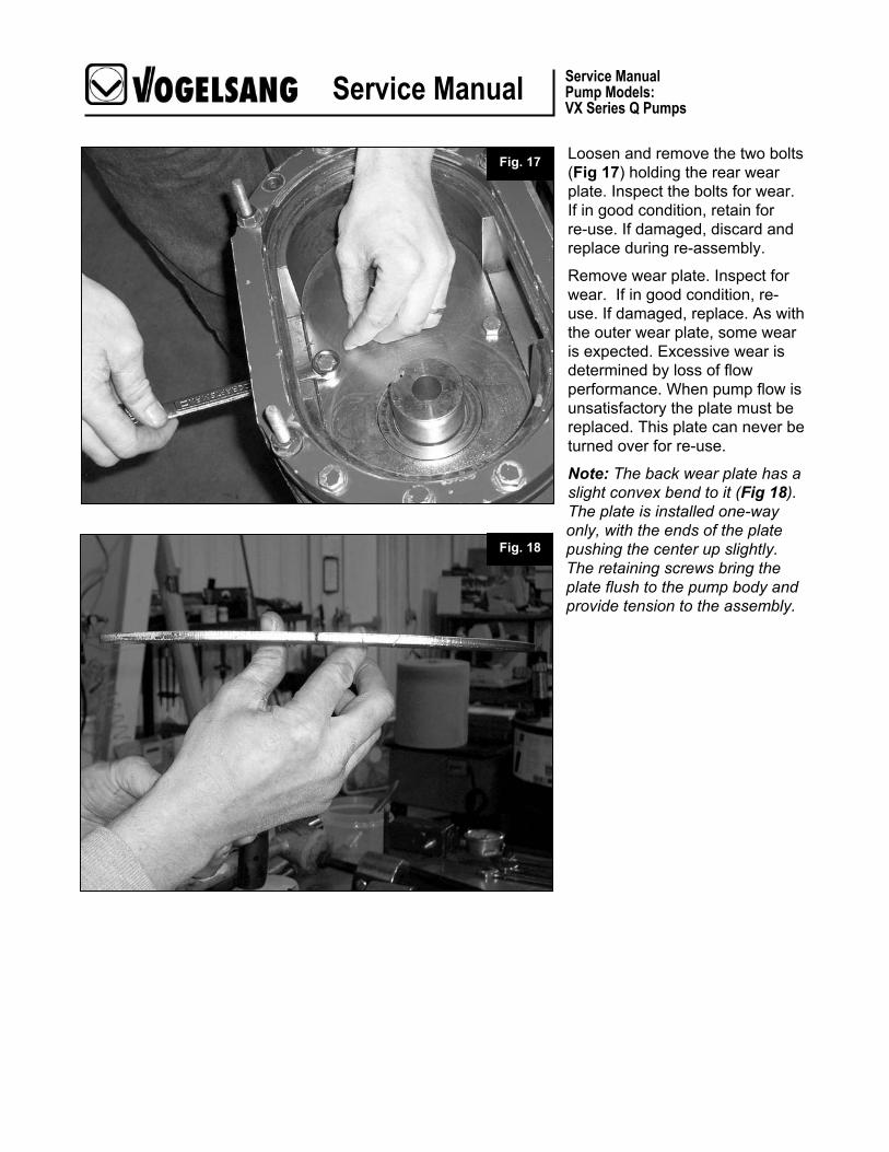
Loosen and remove the two bolts (Fig 17) holding the rear wear plate. Inspect the bolts for wear. If in good condition, retain for re-use. If damaged, discard and replace during re-assembly.
Remove wear plate. Inspect for wear. If in good condition, re-use. If damaged, replace. As with the outer wear plate, some wear is expected. Excessive wear is determined by loss of flow performance. When pump flow is unsatisfactory the plate must be replaced. This plate can never be turned over for re-use.
Note: The back wear plate has a slight convex bend to it (Fig 18). The plate is installed one-way only, with the ends of the plate pushing the center up slightly. The retaining screws bring the plate flush to the pump body and provide tension to the assembly.
Fig. 18
Fig. 17

Service Manual Service Manual Pump Models: VX Series Q Pumps
Special Tool Required
Remove the o-ring (Fig 19) at the top of the mechanical seal cartridge assembly. Discard the o-ring and replace. This o-ring is provided with the mechanical seal assembly if the cartridge is being replaced. Cartridge and block-ring seal assemblies are supplied with 2 small set screws on opposite sides of the outer carrier of the assembly. Remove these small screws using a 2.5mm allen wrench (Fig 20).
These set screws are installed to help keep material out of the threaded holes in the carrier used by the cartridge removal tool (Part # PBA.A014.N1: VX186Q PBA.B020.N1: VX 136Q).
Fig. 20
Fig. 19

Service Manual Service Manual Pump Models: VX Series Q Pumps
Place the cartridge removal tool ring over the shaft of one cartridge assembly at a time. Install two retaining screws to attach the ring to the outer edge of the carrier on the seal assembly, and thread three jacking screws into the removal tool ring (Fig 21). As the jacking screws are tightened into the ring and against the pump housing, the ring will pull the cartridge assembly out of the seal bore.
Pull entire seal assembly up off the lobe shaft. Repeat the procedure for the other mechanical seal assembly. Use an even, slow pressure with the jacking bolts to avoid bending the assembly tool ring. Turn each screw one or two turns at a time, and rotate around the ring increasing pressure with the jacking screws (Fig 22).
Note: If re-using a mechanical seal assembly, the o-ring around the outer circumference of the assembly must be replaced. These o-rings are part of the seal assembly kit when ordered new.
Fig. 22
Fig. 21

Service Manual Service Manual Pump Models: VX Series Q Pumps
Remove the o-ring (Fig 23) from the case. This is the same size o-ring as the one on the outer circumference of the seal assembly.
Caution: The large o-rings used with the mechanical seal assembly are all the same size. However, the o-ring located directly behind the wear plate may be of different material depending on the elastomers used in the pump. All elastomers are standard as NBR, but optional elastomers may be provided, if specified, to combat reaction to specific chemicals being pumped.
Note: This completes the mechanical seal removal procedure. The entire wet-end is now disassembled. If you need to work on the pump’s gearbox end, skip to that section at this point.
Fig. 23

Service Manual Service Manual Pump Models: VX Series Q Pumps
Pressurized plasticoil bottle includes
hand pump(included in kit)
Do not use Non-pressurized glass oil bottle with Block Ring Mechanical Seals.
Installing Block Ring Mechanical Seals
Each Block Ring Mechanical Seal Kit Includes: Block Ring Mechanical Seal, 4 o-rings, & flat washer. Do not reuse your old parts. Note: If you are upgrading to our new Block Ring mechanical seal, you may have our old style non-pressurized oil bottle. All Block Ring seals require a pressurized oil bottle. The pressure setting will depend on your particular application. Follow the instructions in the Oil Bottle Instructions demonstrated earlier in this manual.

Service Manual Service Manual Pump Models: VX Series Q Pumps
Before continuing with cartridge seal replacement: Important! Once you’ve removed the lobes, you must evaluate the condition of the lobe core that will contact the Block Ring. Lobe condition is critical to prevent premature seal failure. (Fig. 24 & 25) Lobes provided before the development of the Block Ring seal may have partial coating on the inner core which mates with the seal. These lobes may show small bits or pieces of the coating in a jagged appearance around the surface which is not acceptable when using Block Ring seals.
New lobes have a smooth, clean, machined appearance and show no jagged bits of coating. If lobes are being reused with the Block Ring seal, attention must be given to the condition of the lobe core, assuring that it has not been damaged.
Unacceptable: Jagged pieces of coating on inner core can lead to seal failure (Fig.26).
Surface is free of gouges or elastomer fragments.
Surface has even elastomer coating with no gouges.
Fig. 24
Fig. 25
Fig. 26

Service Manual Service Manual Pump Models: VX Series Q Pumps
Installing Block Rings Seals: Replace the o-ring inside the blocking chamber casing. Install a new o-ring around the outer body of the new mechanical seal cartridge, liberally coating the o-ring and the inside race of the seal assembly with buffer chamber oil (Fig 27), and slide the cartridge seal and seal removal tool (no bolts) onto shaft and push into the pump body as far as possible by hand (Fig 28).
Lubricate the shaft and slide in the lobe (without key in keyway) against the removal tool (Fig 29). Use the existing pressure disks and strain screw and draw the lobe against the pump body, thereby seating the mechanical seal (Fig 30).
Remove the screw, pressure disks, lobe and removal tool. Repeat this procedure on the other shaft.
Fig. 27 Fig. 28
Fig. 29 Fig. 30
O-ring

Service Manual Service Manual Pump Models: VX Series Q Pumps
Liberally coat seal outer o-ring with buffer chamber oil, and set o-ring in place. Do not attempt to seat the o-ring between the seal body and the pump body. This will occur upon final assembly and tightening of the wear plates (Fig 31).
Coat the smaller o-ring with oil, and slide over shaft and against the seal inner race. Take care that the o-ring is not cut by the sharp edges of the keyway, do not attempt to seat the o-ring (Fig 32).
Install the flat washer over the shaft and against the o-ring (Fig. 33).
Fig. 31
Fig. 32
Fig. 33

Service Manual Service Manual Pump Models: VX Series Q Pumps
Place wear plate (Fig 34) into the pump, insuring that the chromed or ceramic side is facing both you and the wet-end of the pump.
Install the two screws (Fig 35) that hold the wear plate in place, and tighten securely. Rotary Lobes are now ready to be installed.
Fig. 35
Fig. 34

Service Manual Service Manual Pump Models: VX Series Q Pumps
Rotary Lobe Installation Install a key or keys (Fig 36) into the shaft keyway. Take care to insure it is flush with the front end of the shaft.
With the aid of a brush, lubricate the shaft, key, and insides of the lobes with oil. Install the lobes (Fig 37) taking care that the inside lip is facing you. Pumps equipped with only two lobes should have a right lobe on the top, and left lobe on the bottom shaft.
For pumps with multiple sets of lobes mounted on each shaft, start with a right lobe on the top shaft and a left lobe on the bottom shaft. Install the next set using a left lobe on the top shaft and the right lobe on the bottom. Alternate this way until all lobes are installed. The sides of the lobes should form a “V” shape.
Fig. 36
Fig. 37
Inside Lip

Service Manual Service Manual Pump Models: VX Series Q Pumps
Remove and replace the o-rings on the pressure disk (Fig. 38).
With the aid of a brush, lube the inside of the lobes, and the inside and outside o-ring of the pressure disk with hydraulic oil. Then carefully drive into place with a rubber or plastic mallet (Fig. 39).
Fig. 38
Fig. 39

Service Manual Service Manual Pump Models: VX Series Q Pumps
Note: Strain Screws CANNOT be re-used. Install only new Strain Screws.
Lubricate the thread of the strain screw with oil, and install by hand only until it cannot be tightened any further by hand. Repeat on other shaft (fig. 40).
Fit lobe socket to torque wrench, and torque each of the strain screws to the following:
Torque Required VX136 Series = 147 f/lbs.
VX186 Series = 147 f/lbs.
Then loosen each strain screw and re-torque each to 100 f/lbs (Fig. 41).
Fig. 40
Fig. 41

Service Manual Service Manual Pump Models: VX Series Q Pumps
Front Cover Installation Replace the o-ring, and inspect the wear plate for signs of wear. If wear is present, replace the wear plate. Place the cover on the pump, insure it is seated into it’s groove, and securely tighten the four locking nuts (Fig. 42).
Fig. 42

Service Manual Service Manual Pump Models: VX Series Q Pumps
Adding Lubricants Double-check that all drain plugs are installed in the bottom of the pump.
Remove the side bolt from the pumps gear box. From the top, fill the gearbox with oil until begins to run out of the side hole, which translates to filling the gearbox up about halfway. Replace the side drain plug and tighten (Fig 43).
Fill the blocking chamber completely to the top with oil (Fig 44).
Note: Refer back to the instructions regarding the use of the Pressurized Oil Bottle. The appropriate pressure must be set to your particular pump to help ensure maximum mechanical seal liftetime.
Fig. 43
Fig. 44

Service Manual Service Manual Pump Models: VX Series Q Pumps
Disassembly of Gearbox To service the gear end of the pump remove 10 M10x40 metric cap screws around the perimeter of the gear case. Use an 8mm allen wrench extended socket if available. Inspect the split lock washers and replace if necessary. The bolts may be re-used (Fig 45).
Note: If the shafts will be removed, it is necessary to remove the lobes and mechanical seal assemblies first. To service the bearings or gears, the shafts must be removed.
With the aid of a hammer and chisel, carefully tap the key from its keyway, and remove from the pump (Fig. 46).
Remove any burrs from the shaft with the aid of a file or emery cloth. Take care not to injure yourself on the sharp keyway edges.
Fig. 45
Fig. 46

Service Manual Service Manual Pump Models: VX Series Q Pumps
Use a blunt drift in the recesses provided between the gear case (Fig. 47) and the pump body. Never hammer against the feet of the pump. The gear case uses four dowels to position and hold the case to the body. It may require several blows against the drift at various points around to loosen the case.
Once the cover has been loosened, the use of a chisel or similar tool can aid in further removing the case from the 4 dowels used to hold it in place. Use care to loosen the case evenly around the pump body (Fig. 48).
Fig. 47
Fig. 48
Service Manual Service Manual Pump Models: VX Series Q Pumps
Special Tool Required
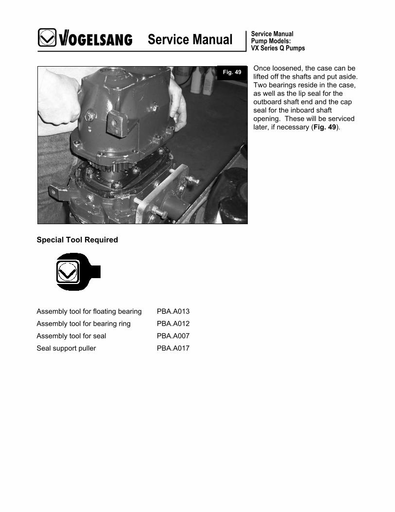
Once loosened, the case can be lifted off the shafts and put aside. Two bearings reside in the case, as well as the lip seal for the outboard shaft end and the cap seal for the inboard shaft opening. These will be serviced later, if necessary (Fig. 49).
Assembly tool for floating bearing PBA.A013
Assembly tool for bearing ring PBA.A012
Assembly tool for seal PBA.A007
Seal support puller PBA.A017
Fig. 49

Service Manual Service Manual Pump Models: VX Series Q Pumps
Remove the case sealing o-ring (Fig. 50). Vogelsang recommends replacing this seal whenever the case is removed, but if it is undamaged and does not indicate excessive compression it may be re-used.
Drive the two shafts from the wet-end of pump through the gear end of pump. Use appropriate drift and heavy hammer as shaft is a tight fit through the double roller bearing (Fig. 51).
Note: Provide soft landing for the shafts as they leave the pump body, or use a helper to hold shafts as they are driven out of the pump.
Fig. 50
Fig. 51

Service Manual Service Manual Pump Models: VX Series Q Pumps
Pump body with shafts removed (Fig. 52).
Use a hammer and chisel to bend the locking washers away from the retainer bolts (Fig. 53). The bolts may be re-used.
Fig. 52
Fig. 53

Service Manual Service Manual Pump Models: VX Series Q Pumps
Use a 17mm wrench to remove the bolts around the bearing retainers (Fig. 54). Discard the locking washers and replace with new.
Drive the roller bearings from the pump body (Fig. 55). Note use of special tool to avoid damaging the bearing if it is to be re-used. (See tool list on previous page).
Fig. 54
Fig. 55

Service Manual Service Manual Pump Models: VX Series Q Pumps
The bearing assembly should emerge from the pump body bore intact (Fig. 56).
Thoroughly clean the area with a fast-drying solvent. We typically use a good quality brake cleaning product to remove all traces of old oil and grease (Fig. 57).
Fig. 56
Fig. 57

Service Manual Service Manual Pump Models: VX Series Q Pumps
Reassembly of Gearbox
Apply liberal coats of oil to all parts during re-assembly of pump (Fig. 58).
Drive bearing assembly fully into the pump body using an appropriate tool to avoid damage to bearing (Fig. 59).
Fig. 58
Fig. 59

Service Manual Service Manual Pump Models: VX Series Q Pumps
The bearing housing should be flush with the pump housing when fully seated (Fig. 60).
Install bearing retainers using new locking washers (Fig. 61). Bolts may be re-used if undamaged.
Fig. 61
Fig. 60

Service Manual Service Manual Pump Models: VX Series Q Pumps
Use a hammer and chisel, or similar tool, to bend one edge of the locking washer up against the retainer bolt head (Fig. 62). Inspect assembly to assure that no locking washer edge extends over the o-ring seat on the corners, as this may impede the re-assembly of the gear case.
If it is necessary to replace the shaft or gear it will be necessary to build an entire new shaft assembly. Carefully inspect the parts list for correct parts for the shaft being rebuilt.
First install the key for the gear (Fig. 63).
Fig. 62
Fig. 63

Service Manual Service Manual Pump Models: VX Series Q Pumps
Align the shaft key with the gear keyway and drive the shaft through the gear until the key aligns with the face of the gear (Fig. 64).
The shaft must be driven through the gear so that the keyways are aligned with the “X” or “XX” facing upwards. Final position of gear is created when spacers and bearing race have been installed (Fig. 65). Arrow points to either the “X” or “XX” depending on which shaft you’re working on.
Fig. 64
Fig. 65

Service Manual Service Manual Pump Models: VX Series Q Pumps
Install spacer on the gearbox end of the shaft, up against the gear face. Then drive the bearing race for the bearing over the shaft and past the cut groove in the shaft (Fig. 66)
Install the circlip into the groove to hold the bearing race in place (Fig. 67).
Install the bearing side spacer. If the drive shaft is being assembled, note that a race must be installed above the circlip to accommodate the lip seal installed later.
Fig. 66
Fig. 67
Service Manual Service Manual Pump Models: VX Series Q Pumps
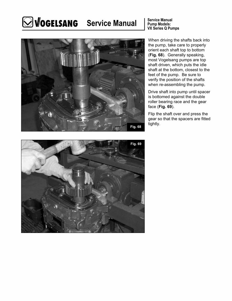
When driving the shafts back into the pump, take care to properly orient each shaft top to bottom (Fig. 68). Generally speaking, most Vogelsang pumps are top shaft driven, which puts the idle shaft at the bottom, closest to the feet of the pump. Be sure to verify the position of the shafts when re-assembling the pump.
Drive shaft into pump until spacer is bottomed against the double roller bearing race and the gear face (Fig. 69).
Flip the shaft over and press the gear so that the spacers are fitted tightly.
Fig. 68
Fig. 69

Service Manual Service Manual Pump Models: VX Series Q Pumps
When installing the second shaft, proper timing of the gears must be maintained by aligning the single tooth marked with an X on one gear between the two teeth marked with an X on the second gear (Fig 70). Failure to properly align the gear teeth will render the pump inoperable.
Second shaft installed with gear teeth properly aligned for correct timing (Fig 71).
Note: Gears are always sold in sets as one part number.
Fig. 70
Fig. 71

Service Manual Service Manual Pump Models: VX Series Q Pumps
To prepare the gear box for re-assembly, remove the retainer clip (Fig. 72) on the lip seal for the outboard shaft.
This clip fits snugly in the machined groove just above the lip seal (Fig. 73).
Fig. 73
Fig. 72

Service Manual Service Manual Pump Models: VX Series Q Pumps
Pry the lip seal out of the bore in the gear box. Discard the seal; it will be replaced in a later step (Fig. 74).
If the case bearing must be replaced, it will have to be removed with a blunt drift against the bearing housing. The bearing race must be replaced on the outboard shaft (Fig. 75). See previous instructions regarding the rebuild of the shafts.
Fig. 75
Fig. 74

Service Manual Service Manual Pump Models: VX Series Q Pumps
The bearing is removed through the inside of the gearbox case. Note the broken roller cage (Fig.76). This is typical when attempting to remove the bearing, therefore remove this bearing only when it will be replaced with a new part.
Remove the retaining clip from the packing disk only if you are replacing the bearing, or if the packing disk is leaking oil. This part does not require routine service (Fig. 77).
Fig. 76
Fig. 77

Service Manual Service Manual Pump Models: VX Series Q Pumps
If the packing disk is to be removed drive it out through the outside of the gearbox case using a suitable tool to avoid bending the disk (Fig. 78).
Replace the o-ring before re-installing the packing disk. Assure proper seating of the o-ring in the packing disk groove before inserting back into case (Fig. 79).
Fig. 78
Fig. 79

Service Manual Service Manual Pump Models: VX Series Q Pumps
Seat the packing disk fully into the bore until it bottoms against the casing. Use a suitable tool to avoid damaging the packing disk. Re-install the retaining clip (Fig. 80).
Place new lip seal in the appropriate bore and seat fully against the gearbox casing. Re-install retaining clip (Fig. 81).
The gearbox housing is now ready for reassembly.
Fig. 81
Fig. 80

Service Manual Service Manual Pump Models: VX Series Q Pumps
Apply a thin coating of lithium grease around the seat for the o-ring and set the o-ring in place. The grease will keep the o-ring in place during assembly. Be sure the o-ring is seated all the way around the pump body (Fig. 82).
Carefully replace the gear housing to the pump (Fig. 83). To properly seat the gear housing, place an allen bolt on opposite sides diagonally. Alternate tightening until the gear housing is seated and snug. Install the remaining bolts.
Fig. 82
Fig. 83

Service Manual Service Manual Pump Models: VX Series Q Pumps
Re-install the drain plug on the gearbox taking care to also re-install the copper washer (Fig. 83).
Note: Proceed to next section regarding the proper method to add lubricants.
Fig. 83

Service Manual Service Manual Pump Models: VX Series Q Pumps
Adding Lubricants Double-check that all drain plugs are installed in the bottom of the pump.
Remove the side bolt from the pumps gear box. From the top, fill the gearbox with oil until its begins to run out of the side hole. Replace the side drain plug and tighten (Fig. 84).
Fill the blocking chamber completely to the top with oil (Fig. 85).
Note: Refer back to the instructions regarding the use of the Pressurized Oil Bottle. The appropriate pressure must be set to your particular pump to help ensure maximum mechanical seal liftetime.
Fig. 84
Fig. 85

Service Manual Service Manual Pump Models: VX Series Q Pumps
2.F.2 Normal Clearances
Because rotary lobes pumps begin to wear on start-up, there is no “normal” clearance between lobe and housing segment or wear plate. When new these clearances are less than 1mm. As the lobes and wear plates wear these clearances increase. As far as the pump itself is concerned this clearance does not matter.
2.F.3 Acceptable Limits for Wearing Parts
Rotary lobe pumps, by design, begin to show wear almost immediately upon start-up. The rate of wear on lobes and wet-end parts is dependent upon pump speed and the abrasion quality of material being pumped. Consequently, no “normal” wear characteristics can be identified.
Generally, pump lobes are “worn out” when the output flow no longer meets acceptable expectations. At this point lobes are replaced, or housing segments are adjusted to regain acceptable flow rates.
2.F.4 Critical Torque Specs
Only the lobe strain screw has a critical torque specification. All other fasteners, bolts and nuts are to be tightened to generally accepted standards.
Torque specification for lobe strain screws: Tighten initially to 147 ft.lbs. (wet with oil torque) Loosen to less than 100 ft. lbs. Re-tighten to 100 ft lbs.

Service Manual Service Manual Pump Models: VX Series Q Pumps
2.F.5 Troubleshooting N
o D
isch
arge
Bel
ow C
apac
ity
Irreg
ular
Dis
char
ge
Lost
Prim
e
Pum
p S
talls
at S
tartu
p
Pum
p O
verh
eats
Mot
or O
verh
eats
Exc
essi
ve P
ower
Dra
w
Noi
se &
Vib
ratio
n
Pum
p E
lem
ent W
ater
Sei
zure
Causes Solution
X Incorrect direction of rotation
Reverse Motor
X Pump not primed
Expel gas from supply line and pumping chamber to introduce liquid.
X X X X X Insufficient NPSH available
X X X X Product vaporizing in supply line.
Increase supply line diameter. Increase suction head. Simplify piping and/or reduce length. Reduce pump speed. Decrease liquid temperature. Check effect of increased viscosity on available and permitted power inputs.
X X X X X Air entering supply line. Remake pipe work
X X X X Gas Supply
Expel gas from supply line and pumping chamber to introduce liquid.
X X X X X Insufficient head above supply vessel outlet
False product level. Lower outlet position. Increase submergence of supply line.
X X X Foot valve strainer obstructed or blocked.
Service Fittings.
X X X X X X X Liquid viscosity above rated figure.
Decrease pump speed. Increase liquid temp.
X Liquid viscosity below rated figure.
Increase pump speed. Decrease liquid temp.

Service Manual Service Manual Pump Models: VX Series Q Pumps
No
Dis
char
ge
Bel
ow C
apac
ity
Irreg
ular
Dis
char
ge
Lost
Prim
e
Pum
p S
talls
at S
tartu
p
Pum
p O
verh
eats
Mot
or O
verh
eats
Exc
essi
ve P
ower
Dra
w
Noi
se &
Vib
ratio
n
Pum
p E
lem
ent W
ater
Sei
zure
Causes Solution
X X X XLiquid temp. above rated figure.
Cool the liquid prior to pumping
X X X Liquid temp. below rated figure.
Heat the liquid prior to pumping
X X XUnexpected solids in product.
Clean the system. Add strainer to supply line.
X X X X X X X X X XDelivery pressure above rated figure.
Check for obstruction. Simplify supply line.
Seal flushing inadequate Check that fluid flows freely into seal. Increase flow rate.
X X X X Pump speed above rated figure.
Decrease pump speed.
Pump speed below rated figure.
Increase pump speed.
X X X X X X XRotor case strained by pipe work.
Align pipes. Add flexible pipes or expansion fittings.
X X X X Belt Drive Slipping Tighten belt to specified tension.
X Flexible coupling misaligned.
Adjust flange alignment.
X X X X X XInsecure pump drive mountings
Add lock washers and retighten.
X X X X X X XShaft bearing wear or failure.
Call Vogelsang or distributor for advice.
X X X X XWorn unsynchronized timing gears
Call Vogelsang or distributor for advice.
X X X X X X XGear case oil level incorrect.
Refer to oil level instructions.

Service Manual Service Manual Pump Models: VX Series Q Pumps
No
Dis
char
ge
Bel
ow C
apac
ity
Irreg
ular
Dis
char
ge
Lost
Prim
e
Pum
p S
talls
at S
tartu
p
Pum
p O
verh
eats
Mot
or O
verh
eats
Exc
essi
ve P
ower
Dra
w
Noi
se &
Vib
ratio
n
Pum
p E
lem
ent W
ater
Exc
essi
ve S
eal W
ear
Sei
zure
Causes Solution
X X Metal to metal contact of pumping element.
Check rated and duty pressures.
X X Worn pumping element. Install new components
X X Relief valve leakage
Adjust pressure setting. Examine & clean seating surfaces. Install new components.
X X Relief valve chatter Check water sealing surfaces & guides. Install new components.

Service Manual Service Manual Pump Models: VX Series Q Pumps
Warranties 4.A.1 Warranty Information

Service Manual Service Manual Pump Models: VX Series Q Pumps
Field Testing Records 5.A.1 Documents for Testing at Initial Startup

Service Manual Service Manual Pump Models: VX Series Q Pumps
5.A.1 Documents for Testing at Initial Startup (continued)
Service Manual Service Manual Pump Models: VX Series Q Pumps
5.A.1 Documents for Testing at Initial Startup (continued)