SERVICE MANUAL NUMBER 14 DRIVE SHAFT HOUSING … · Inspect the locating pin holes on the drive...
50
3 A DRIVE SHAFT HOUSING SERVICE MANUAL NUMBER 14 90-818177--3 APRIL 2001 Page 3A-1 STERNDRIVE UNIT Section 3A - Drive Shaft Housing Table of Contents Specifications 3A-2 . . . . . . . . . . . . . . . . . . . . . . . Torque Specifications 3A-2 . . . . . . . . . . . . . Upper Drive Shaft Bearing Preload 3A-2 . . U-joint Bearing Preload 3A-2 . . . . . . . . . . . . Gear Shimming Specifications 3A-2 . . . . . . Lubricants/Sealers/Adhesives 3A-3 . . . . . . Special Tools 3A-3 . . . . . . . . . . . . . . . . . . . . . Drive Shaft Housing Exploded Parts View 3A-4 . . . . . . . . . . . . . . . . . . . . . . . . . . . . . . U-joint and Driven Gear Components 3A-4 . . . . . . . . . . . . . . . . . . . . Drive Shaft Components 3A-6 . . . . . . . . . . . Special Information 3A-7 . . . . . . . . . . . . . . . . . . Top Cover Bearing Cup 3A-7 . . . . . . . . . . . . Universal Joint Bearing Set 3A-7 . . . . . . . . Drive Shaft Housing/Gear Housing 3A-7 . . . . Separation 3A-7 . . . . . . . . . . . . . . . . . . . . . . . Drive Shaft Housing and Component Disassembly 3A-9 . . . . . . . . . . . . . . . . . . . . . . . Drive Unit Gear Ratio Identification 3A-9 . . Drive Shaft Housing Cleaning and Inspection 3A-15 . . . . . . . . . . . . . . . . . . . . . . . . . U-joint Assembly - Inspection and Disassembly 3A-15 . . . . . . . . . . . . . . . . . . . . Oil Seal Carrier Subassembly 3A-17 . . . . . . Pinion Gear Subassembly 3A-18 . . . . . . . . . U-joint Subassembly 3A-21 . . . . . . . . . . . . . . U-joint Assembly 3A-24 . . . . . . . . . . . . . . . . . Top Cover Subassembly 3A-26 . . . . . . . . . . . Upper Driven Gear Subassembly 3A-29 . . . Drive Shaft Housing Reassembly 3A-33 . . . . . . Drive Shaft Housing Inspection 3A-33 . . . . . Installation 3A-33 . . . . . . . . . . . . . . . . . . . . . . . Assembly and Checking Driven Gear Location 3A-35 . . . . . . . . . . . . . . . . . . . Adjusting Gear Location 3A-38 . . . . . . . . . . . Seal Installation 3A-39 . . . . . . . . . . . . . . . . . . Checking and Adjusting Drive Gear Location 3A-43 . . . . . . . . . . . . . . . . . . . Final Reassembly 3A-45 . . . . . . . . . . . . . . . . . . . Joining Drive Shaft Housing/Gear Housing 3A-47 . . . . . . . . . . . . . . . . . . . . . . . . . . .
Transcript of SERVICE MANUAL NUMBER 14 DRIVE SHAFT HOUSING … · Inspect the locating pin holes on the drive...

3A
DRIVE SHAFT HOUSINGSERVICE MANUAL NUMBER 14
90-818177--3 APRIL 2001 Page 3A-1
STERNDRIVE UNITSection 3A - Drive Shaft Housing
Table of Contents
Specifications 3A-2. . . . . . . . . . . . . . . . . . . . . . . Torque Specifications 3A-2. . . . . . . . . . . . . Upper Drive Shaft Bearing Preload 3A-2. . U-joint Bearing Preload 3A-2. . . . . . . . . . . . Gear Shimming Specifications 3A-2. . . . . . Lubricants/Sealers/Adhesives 3A-3. . . . . . Special Tools 3A-3. . . . . . . . . . . . . . . . . . . . .
Drive Shaft Housing Exploded Parts View 3A-4. . . . . . . . . . . . . . . . . . . . . . . . . . . . . .
U-joint and Driven Gear Components 3A-4. . . . . . . . . . . . . . . . . . . . Drive Shaft Components 3A-6. . . . . . . . . . .
Special Information 3A-7. . . . . . . . . . . . . . . . . . Top Cover Bearing Cup 3A-7. . . . . . . . . . . . Universal Joint Bearing Set 3A-7. . . . . . . .
Drive Shaft Housing/Gear Housing 3A-7. . . . Separation 3A-7. . . . . . . . . . . . . . . . . . . . . . .
Drive Shaft Housing and Component Disassembly 3A-9. . . . . . . . . . . . . . . . . . . . . . .
Drive Unit Gear Ratio Identification 3A-9. . Drive Shaft Housing Cleaning and Inspection 3A-15. . . . . . . . . . . . . . . . . . . . . . . . .
U-joint Assembly - Inspection and Disassembly 3A-15. . . . . . . . . . . . . . . . . . . . Oil Seal Carrier Subassembly 3A-17. . . . . . Pinion Gear Subassembly 3A-18. . . . . . . . . U-joint Subassembly 3A-21. . . . . . . . . . . . . . U-joint Assembly 3A-24. . . . . . . . . . . . . . . . . Top Cover Subassembly 3A-26. . . . . . . . . . . Upper Driven Gear Subassembly 3A-29. . .
Drive Shaft Housing Reassembly 3A-33. . . . . . Drive Shaft Housing Inspection 3A-33. . . . . Installation 3A-33. . . . . . . . . . . . . . . . . . . . . . . Assembly and Checking Driven Gear Location 3A-35. . . . . . . . . . . . . . . . . . . Adjusting Gear Location 3A-38. . . . . . . . . . . Seal Installation 3A-39. . . . . . . . . . . . . . . . . . Checking and Adjusting Drive Gear Location 3A-43. . . . . . . . . . . . . . . . . . .
Final Reassembly 3A-45. . . . . . . . . . . . . . . . . . . Joining Drive Shaft Housing/Gear Housing 3A-47. . . . . . . . . . . . . . . . . . . . . . . . . . .

DRIVE SHAFT HOUSING SERVICE MANUAL NUMBER 14
Page 3A-2 90-818177--3 APRIL 2001
Specifications
Torque Specifications
TorqueDescription
lb-in. lb-ft Nm
Top Cover Screws 20 27
U-joint Retainer Nut* 200 271
Nuts, Bolts And Washers 35 47.5
Nut 35 47.5
Screw 28 41
Trim Tab Screw 23 31
Dipstick 17.5 2
Oil Vent Screw 40 4
*See Torque Wrench Chart.
Upper Drive Shaft Bearing Preload
TorqueDescription
lb-in. Nm
New Bearings 8 0.9
Used Bearings* 5 0.6
*Bearings are considered used if spun under load once.
U-joint Bearing Preload
TorqueDescription
lb-in. Nm
New Bearings 6-10 0.7-1.1
Used Bearings* 3-7.5 0.3-0.8
*Bearings are considered used if spun under load once.
Gear Shimming Specifications
Gear LocationDescription
inches millimeters
Drive Gear .025 0.64
Driven Gear .025 0.64

DRIVE SHAFT HOUSINGSERVICE MANUAL NUMBER 14
90-818177--3 APRIL 2001 Page 3A-3
Lubricants/Sealers/Adhesives
Description Part Number
Quicksilver 2-4-C Marine LubricantWithTeflon
92-825407A12
Quicksilver U-jointAnd Gimbal Bearing-Grease
92-828052A2
3M Brand Adhesive 92-86166-1
Quicksilver Needle Bearing AssemblyLubricant
92-825265A1
Quicksilver Perfect Seal 92-34227-1
Permatex Ultra Blue Silicone Sealant Obtain Locally
Quicksilver Special Lubricant 101 92-13872A1
Quicksilver High Performance Gear Lube 92-816026A4
Special Tools
Description Part Number
U-joint Adaptor 91-38756
Bearing Cup Driver 91-38918
Bearing Cup Driver 91-808053
Bearing Cup Driver 91-33493
Bearing Cup Driver 91-36577
Driver Rod 91-37323
Driver Tool 91-90774
Oil Seal Driver 91-817570
Shimming Tool (Driven Gear) 91-60526
Shimming Tool (Driven Gear) 91-854377
Shimming Tool (Drive Gear) 91-60523
Slide Hammer Puller 91-34569A1
Torque Wrench (lb-in.) 91-66274
U-joint Bearing Retainer Wrench 91-17256
Universal Puller Plate 91-37241

DRIVE SHAFT HOUSING SERVICE MANUAL NUMBER 14
Page 3A-4 90-818177--3 APRIL 2001
Drive Shaft Housing Exploded Parts View
U-joint and Driven Gear Components
�����
�
��
��
��
��
��
��
��
�
��
��
�
��
��
�
�
�
�
��
��
��
��
���
��
���
��
�
��
B
D
A
A
C

DRIVE SHAFT HOUSINGSERVICE MANUAL NUMBER 14
90-818177--3 APRIL 2001 Page 3A-5
1 - Drive Shaft Housing2 - Screw3 - O-ring Or Washer4 - Spring Assembly5 - Oil Seal6 - Wear Pad7 - Plug8 - Universal Joint9 - Yoke, Universal Joint-gear End
10 - Socket, Center-universal Joint11 - Cross And Bearing12 - Yoke Assembly, Universal Joint-cou-
pling End13 - O-ring14 - Retainer15 - Ring
16 - O-ring17 - Carrier Assembly18 - Oil Seal19 - Roller Bearing And Cups20 - Spacer Cup (S/N Prior To 0L100009)21 - Shim22 - Shim23 - Drive Gear Assembly24 - Roller Bearing And Cup25 - Washer26 - Nut27 - Shims28 - Ground Plate29 - Screw30 - Spacer Cup (S/N 0L100009 And
Above)
Lubricants/Sealers/Adhesives
NOTE: Fill Drive With High Performance Gear Lube
A - 2-4-C Marine Lubricant With Teflon
B - Quicksilver High Performance Gear Lube
C- Special Lubricant 101
D - Quicksilver Engine Coupler Spline Grease
DRIVE SHAFT HOUSING SERVICE MANUAL NUMBER 14
Page 3A-6 90-818177--3 APRIL 2001
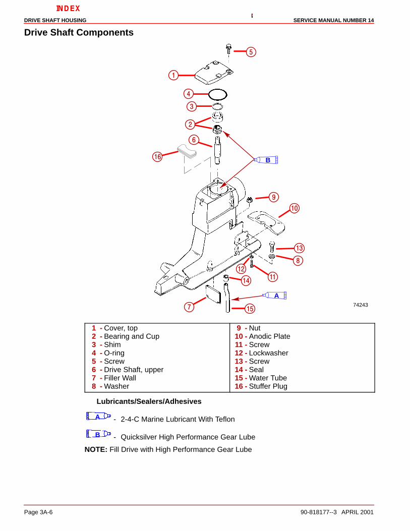
Drive Shaft Components
74243
��
��
��
��
��
��
�
�
�
�
�
�
�
�
B
A
1 - Cover, top2 - Bearing and Cup3 - Shim4 - O-ring5 - Screw6 - Drive Shaft, upper7 - Filler Wall8 - Washer
9 - Nut10 - Anodic Plate11 - Screw12 - Lockwasher13 - Screw14 - Seal15 - Water Tube16 - Stuffer Plug
Lubricants/Sealers/Adhesives
A - 2-4-C Marine Lubricant With Teflon
B - Quicksilver High Performance Gear Lube
NOTE: Fill Drive with High Performance Gear Lube

DRIVE SHAFT HOUSINGSERVICE MANUAL NUMBER 14
90-818177--3 APRIL 2001 Page 3A-7
Special Information
Top Cover Bearing CupThe later style bearing cup is thinner than the earlier style cup.
75240
a b
a - Earlier Style Bearing Cup 1.938 in. (49 mm) Diameter (Prior to S/N OF680000)b - Later Style Bearing Cup 1.781 in. (45 mm) Diameter (S/N OF680000 And
Above)
Universal Joint Bearing SetIMPORTANT: Alpha One Sterndrive Units beginning with serial number 0L100009 andabove no longer use the cone spacer between the bearings in the U-joint assemblyto set the bearing preload. A new procedure has been established for adjusting thispreload and is covered in the following instructions. The O.D. of the new drive gearbearing carrier has changed to 3.265 in. (82.9 mm).
Drive Shaft Housing/Gear Housing
Separation1. Clamp the unit on the gear case anti-ventilation plate in a suitable fixture.
2. Trim drive unit to full UP/OUT position.
3. Remove the oil fill/drain plug.
75703
23264a
b
a - Fill/Drain Screwb - Sealing Washer

DRIVE SHAFT HOUSING SERVICE MANUAL NUMBER 14
Page 3A-8 90-818177--3 APRIL 2001
4. Remove the drive shaft housing vent screw. Allow the drive unit to drain completely.
70131
ab
a - Vent Screwb - Sealing Washer
5. If equipped, mark the trim tab position with a piece of tape on the gear housing andremove the trim tab.
70116a
a - Trim Tab
6. Remove the aft screw (in the trim tab well of the gear housing).
7. Remove the bolts, nuts and washers from the port and starboard sides of the unit.

DRIVE SHAFT HOUSINGSERVICE MANUAL NUMBER 14
90-818177--3 APRIL 2001 Page 3A-9
8. Remove the nut from the forward end of the unit.
75703
b a
c
a - Nuts, Bolts And Washersb - Nutc - Screw
9. Lift the drive shaft housing straight off of the gear case and set aside.
NOTE: It may be necessary to lightly tap housing with a synthane hammer to assist removal.
Drive Shaft Housing and Component Disassembly
Drive Unit Gear Ratio IdentificationAll drive unit gear ratios are identified on each drive in two places. It is important to note theratio of the drive unit before preceding with any repairs. The first place to look is on the decalon the port side of the drive shaft housing. It will have a number such as (1.50R) and thenthe serial number. The second place to look will be on the universal joint splined yoke. It willbe identified with a letter such as (F). This method is explained in the following chart.
ALPHA
A 2.0:1
B 1.98:1
C 1.62:1, 1.65:1
D 1.81:1, 1.84:1
F 1.47:1, 1.50:1
H 1.32:1
K 2.40:1
M 1.50:1 MAGNUM

DRIVE SHAFT HOUSING SERVICE MANUAL NUMBER 14
Page 3A-10 90-818177--3 APRIL 2001
This will be true for new or with drive units that have not been altered. A drive unit could havehad the gear ratio changed for high altitude, which would void any application of the abovechart. The gear ratio then would have to be determined by counting the teeth on the drivegear and the driven gear in the drive shaft housing and using the following chart forreference.
Tooth Count Ratio Drive Driven
14-28 2.40:1 20 24
14-28 2.0:1 24 24
17-28 1.98:1 20 24
17-28 1.81:1, 1.84:1 17 19
17-28 1.62:1, 1.65:1 24 24
17-28 1.47:1, 1.50:1 22 20
17-28 1.32:1 20 16
1. Remove the dipstick and washer, if present, in the top cover and remove the fastenerssecuring the top cover to the drive shaft housing. Lift the top cover straight off. It maybe necessary to pry the top cover off by using a pair of screwdrivers (one on each side)in the slots provided at the junction of the top cover and the drive shaft housing.
70118
c
a
b
a - Top Coverb - Screwsc - Dipstick (Early Models)
2. Remove the U-joint retainer.
70209
ab
a - U-joint Retainerb - U-joint Retainer Tool

DRIVE SHAFT HOUSINGSERVICE MANUAL NUMBER 14
90-818177--3 APRIL 2001 Page 3A-11
3. Remove the U-joint assembly by pulling it straight out.
NOTE: A synthane hammer may be used to tap on housing to assist removal.
70122
a
a - U-joint Assembly
4. Remove the shim pack and the spacer ring. Measure and make note of the shim packthickness. The shims may be reused if they are not damaged.
70123
a
b
a - Shimsb - Spacer Ring (On Some Models)

DRIVE SHAFT HOUSING SERVICE MANUAL NUMBER 14
Page 3A-12 90-818177--3 APRIL 2001
5. Remove the driven gear assembly by pulling it straight up and out of the drive shafthousing.
70124
a
a - Driven Gear Assembly
IMPORTANT: Removal of the driven gear bearing cup is only necessary forreplacement of the cup or drive shaft housing, installing new oil seals and/or thechanging of the shims below the cup for adjusting the driven gear location.
6. Remove the driven gear bearing cup and shim(s). Measure and make note of the shimpack thickness. Discard the shim(s) if they have been damaged.
70128
a
b
a - Bearing Cupb - Slide Hammer Puller
DRIVE SHAFT HOUSINGSERVICE MANUAL NUMBER 14
90-818177--3 APRIL 2001 Page 3A-13
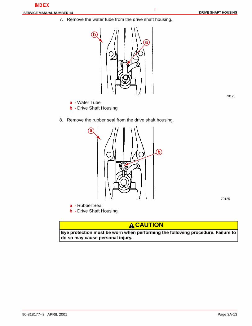
7. Remove the water tube from the drive shaft housing.
70126
b
a
a - Water Tubeb - Drive Shaft Housing
8. Remove the rubber seal from the drive shaft housing.
70125
a
b
a - Rubber Sealb - Drive Shaft Housing
CAUTIONEye protection must be worn when performing the following procedure. Failure todo so may cause personal injury.

DRIVE SHAFT HOUSING SERVICE MANUAL NUMBER 14
Page 3A-14 90-818177--3 APRIL 2001
9. Remove the drive shaft housing oil seals as shown in the figure below.
70129
a
b
a - Oil Seals (2)b - Suitable Tool

DRIVE SHAFT HOUSINGSERVICE MANUAL NUMBER 14
90-818177--3 APRIL 2001 Page 3A-15
Drive Shaft Housing Cleaning and Inspection
CAUTIONEye protection must be worn when performing the following procedure. Failure todo so may cause personal injury.
1. Clean the drive shaft housing thoroughly with a suitable solvent and a hard bristle brush.Dry the drive shaft housing thoroughly using compressed air. Ensure that all sealants,locking agents and debris are removed.
2. Inspect the drive shaft housing for corrosion and any other damage. Excessive damagewill require the replacement of the drive shaft housing.
3. Inspect the U-joint retainer threads in the drive shaft housing for corrosion, strippedand/or cross-threaded threads. Excessive damage to the threads will require thereplacement of the drive shaft housing.
4. Inspect for blockage of the water and oil passages. Clean as necessary.
U-joint Assembly - Inspection and Disassembly1. Remove and discard the two small O-rings on the spline end of the U-joint.
2. Clamp the U-joint retainer tool in a vise and insert the U-joint assembly into it from thetop.
CAUTIONWhen accomplishing the following steps it is necessary to prevent the U-joint fromfalling when removing the lock nut. Failure to follow this instruction may cause per-sonal injury and/or damage to the assembly.
3. While holding the U-joint, remove the locknut and washer from the U-joint shaft.
70210a
bb
a
Earlier Model Later Model. . . . . . . . . . . . . . . . . . . . . . . . . . . . . . a - U-joint Assemblyb - U-joint Retainer Tool

DRIVE SHAFT HOUSING SERVICE MANUAL NUMBER 14
Page 3A-16 90-818177--3 APRIL 2001
CAUTIONEye protection must be worn when performing the following procedure. Failure todo so may cause personal injury.
4. Remove gear and bearing assembly from shaft.
5. Remove bearings from gear and ensure that the bearing cones and cups remaintogether as a set utilizing a piece of wire to keep them together.
IMPORTANT: After disassembly inspect the bearing cones and cups for damage thatmay have occurred during removal from the gear. If either of the bearing cups orcones have been damaged, it will be necessary to replace both bearing cups and bothbearing cones.
22393
a
b
c
a - Gear/Bearing Assemblyb - Universal Puller Platec - Suitable Mandrel
6. Clean all components with a suitable solvent and dry them thoroughly usingcompressed air.
7. Inspect the pinion gear bearings by rotating them by hand. Rough, uneven movementor a loose condition indicates the need for replacement of the bearings and cups.
8. Inspect the large O-ring around the oil seal carrier for damage or excessivecompression. Replace the O-ring if it is found to be defective.
9. Inspect the gear for pitting, chipped or broken teeth, hairline fractures and excessive oruneven wear. Replace both the drive (pinion) gear and the driven gear if any of theseconditions exist.
10. Inspect the U-joint retainer for damage, cracks and/or broken or corroded threads.Replace it if any of these conditions are found.

DRIVE SHAFT HOUSINGSERVICE MANUAL NUMBER 14
90-818177--3 APRIL 2001 Page 3A-17
11. Inspect the thrust ring for cracks, damage and/or excessive wear. Replace it if any arefound.
23010abcd e
f
a - Retainerb - Thrust Ringc - O-ring, Larged - Oil Seal Carriere - U-jointf - O-rings
Oil Seal Carrier SubassemblyINSPECTION AND DISASSEMBLY
1. Inspect the oil seal carrier and oil seal for damage or excessive wear. If the carrier isfound to be defective, replace the carrier and the oil seal as a unit. If only the oil seal isfound to be defective, replace it as outlined.
a. Remove the U-joint oil seal from the oil seal carrier using a punch and a hammer.
23009
a
b
a - Oil Sealb - Oil Seal Carrier

DRIVE SHAFT HOUSING SERVICE MANUAL NUMBER 14
Page 3A-18 90-818177--3 APRIL 2001
OIL SEAL CARRIER - REASSEMBLY
1. Assemble the oil seal into the oil seal carrier by pressing it with the lip of the seal facingaway from the stepped side of the carrier. Use the oil seal driver tool (91-36577) to pressthe seal into place.
23009
a
c
b
a - Oil Sealb - Oil Seal Carrierc - Oil Seal Driver Tool
Pinion Gear SubassemblyDISASSEMBLY
NOTE: For removal of bearing pack from gear, refer to page 3A-16 .
NOTE: If by previous inspection both the pinion gear and the bearings have been found tobe in good condition, skip this whole section.
NOTE: If by previous inspection both the pinion gear and the bearings have been found tobe in need of replacement, order new parts, (pinion gear, pinion gear bearings and cups anddriven gear), skip this disassembly section and go to “Reassembly.”
NOTE: If by previous inspection the pinion gear has been found to be in need of replacementboth the pinion gear and the driven gear must be replaced as a set.
NOTE: If by previous inspection the bearings have been found to be in need of replacementboth bearing cups and both bearing cones must be replaced as a set.
IMPORTANT: If the bearings are to be re-used (when replacing only the pinion anddriven gears), make sure that the bearing cones and cups were kept together in theiroriginal pairing and are reassembled in the same order, (i.e. the bearing cone and cupthat were closest to the old gears’ teeth must be reinstalled closest to the new gears’teeth).

DRIVE SHAFT HOUSINGSERVICE MANUAL NUMBER 14
90-818177--3 APRIL 2001 Page 3A-19
REASSEMBLY
IMPORTANT: Lightly lubricate the gears and bearings with Quicksilver HighPerformance Gear Lube before installing. Bearings and gears must be lubricated toobtain accurate preload readings.
1. Press the bearing cone onto the pinion gear until it seats fully against the back side ofthe gear.
22393
a
b
c
a - Driver Tool (91-90774)b - Bearing Conec - Drive Gear
2. Place the bearing cup onto the bearing cone.
3. Place the large bearing spacer onto the bearing cup.
4. Place the second bearing cup onto the spacer.
IMPORTANT: Do not over-press the second bearing cone, as damage to one or bothof the bearings could occur. If an over-pressed condition occurs (the spacer does notmove freely), completely disassemble the bearings from the gear and start again.

DRIVE SHAFT HOUSING SERVICE MANUAL NUMBER 14
Page 3A-20 90-818177--3 APRIL 2001
5. Press the bearing cone (positioned as shown in the next figures) onto the pinion gearuntil the bearing rollers make light contact with the bearing cup.
22393
ab
c
d
Models With Serial Numbers Prior To 0L100009a - Bearing Coneb - Bearing Cupc - Spacer (Must Move Freely)d - Suitable Mandrel - Must Push On Inner Bearing Race
75631
a
bc
d
Models With Serial Numbers 0L100009 and Latera - Bearing Coneb - Bearing Cupc - Spacer (Must Move Freely)d - Suitable Mandrel – Must Push On Inner Bearing Race
DRIVE SHAFT HOUSINGSERVICE MANUAL NUMBER 14
90-818177--3 APRIL 2001 Page 3A-21
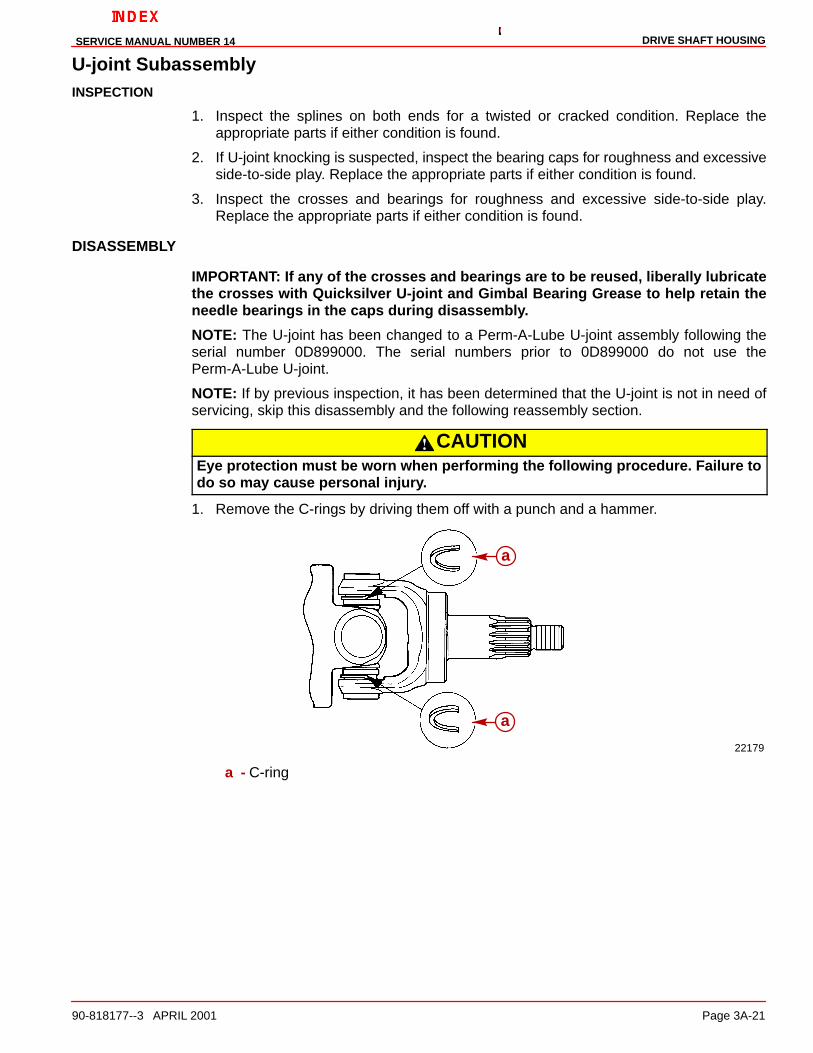
U-joint SubassemblyINSPECTION
1. Inspect the splines on both ends for a twisted or cracked condition. Replace theappropriate parts if either condition is found.
2. If U-joint knocking is suspected, inspect the bearing caps for roughness and excessiveside-to-side play. Replace the appropriate parts if either condition is found.
3. Inspect the crosses and bearings for roughness and excessive side-to-side play.Replace the appropriate parts if either condition is found.
DISASSEMBLY
IMPORTANT: If any of the crosses and bearings are to be reused, liberally lubricatethe crosses with Quicksilver U-joint and Gimbal Bearing Grease to help retain theneedle bearings in the caps during disassembly.
NOTE: The U-joint has been changed to a Perm-A-Lube U-joint assembly following theserial number 0D899000. The serial numbers prior to 0D899000 do not use thePerm-A-Lube U-joint.
NOTE: If by previous inspection, it has been determined that the U-joint is not in need ofservicing, skip this disassembly and the following reassembly section.
CAUTIONEye protection must be worn when performing the following procedure. Failure todo so may cause personal injury.
1. Remove the C-rings by driving them off with a punch and a hammer.
22179
a
a
a - C-ring

DRIVE SHAFT HOUSING SERVICE MANUAL NUMBER 14
Page 3A-22 90-818177--3 APRIL 2001
2. Using the adaptor and a U-joint press, press one bearing cap in until the oppositebearing is pressed out into the adaptor. Remove the loose bearing cap.
22180
a
b
a - U-joint Pressb - Adaptor (91-38756)
3. Turn the U-joint assembly 180 degrees and press on the cross until the second bearingis pressed out into the adapter. Remove each pair of bearing caps in this manner.
INSPECTION
1. Clean all components (except the bearing caps and bearings) with a suitable solventand dry thoroughly with compressed air.
2. Inspect the bearing cap seals for damage or deterioration. Replace bearing caps andcrosses if either condition is found.
IMPORTANT: If the crosses are found to be in need of replacement, all the needlebearings, caps and cross must be replaced. Do not reuse any individualcomponent(s) of a cross assembly.
3. Inspect the bearing surfaces of the crosses for hairline fractures, excessive pitting, wear,grooves, scores, uneven wear, discoloration (from overheating) and embeddedparticles, or breakage. Replace the appropriate cross assembly (cross, bearings andcaps) if any of these conditions exist.
4. Inspect all remaining components for excessive wear or damage. Replace theappropriate components if either is found.

DRIVE SHAFT HOUSINGSERVICE MANUAL NUMBER 14
90-818177--3 APRIL 2001 Page 3A-23
REASSEMBLY
IMPORTANT: Use only Quicksilver U-joint and Gimbal Bearing Grease for lubricatingthe U-joint bearings. The use of any other lubricant will decrease the life of thebearings.
NOTE: When initially positioning the crosses in the yoke, be sure that the grease fittings arefacing toward the coupler (long end) yoke.
1. Using the adaptor and a U-joint press, assemble the cross between the yoke andpress one bearing cup in until it is nearly through its yoke.
22180
a
b
a - U-joint Pressb - Adaptor (91-38756)
2. Turn the U-joint assembly 180 degrees and press the other bearing cup on until bothcups are positioned correctly. Assemble each pair of bearings in this manner.
3. Install the C-rings into the groove of the bearing caps. Ensure that all of the C-ringsare properly seated.
22182
b
a
a - C-ringb - Hammer
4. Repeat Step 1 for all pairs of bearings.
5. Lubricate the grease fittings with Quicksilver U-joint and Gimbal Bearing Grease.

DRIVE SHAFT HOUSING SERVICE MANUAL NUMBER 14
Page 3A-24 90-818177--3 APRIL 2001
U-joint Assembly
REASSEMBLY
1. On Models With Serial Numbers Prior To 0L100009: temporarily install a hose clampon the bearing assembly to keep the bearing cups aligned with the spacer whileaccomplishing the next step.
70092
b
a77709
b
Earlier Style Later Style. . . . . . . . . . . . . . . . . . . . . . . . . . . . . . . . a - Hose Clampb - Bearing Cups
2. Assemble the retainer ring, thrust washer, O-ring and oil seal carrier. Then assemble thegear/bearing assembly, the washer and the nut. Tighten the nut finger tight.
75632
a
b
c
de
fg
h
a - Gear Assemblyb - Washerc - Nutd - Oil Seal Carriere - O-ringf - Thrust Washerg - Retainer Ringh - U-joint Assembly
3. Place the U-joint into the U-joint retainer tool.

DRIVE SHAFT HOUSINGSERVICE MANUAL NUMBER 14
90-818177--3 APRIL 2001 Page 3A-25
4. Insert a suitable tool, such as a screwdriver, between the U-joint yokes as shown in thenext figure, to prevent the U-joint from rotating when turning down the pinion nut. Turnthe pinion nut down until the preload is on the bearings. Remove the screwdriver orholding device.
70210
a
b
d
c
e
Models With Serial Numbers Prior To 0L100009
75633
a
d
e
cb
Models With Serial Numbers After 0L100009a - U-joint Assemblyb - Vicec - U-joint Retainer Tool (91-17256)d - Screwdrivere - Socket and Ratchet Wrench

DRIVE SHAFT HOUSING SERVICE MANUAL NUMBER 14
Page 3A-26 90-818177--3 APRIL 2001
SETTING BEARING PRELOAD
1. Set the preload by holding the bearings and turning the pinion nut at least two fullrevolutions. Check preload by turning the pinion nut very slowly a third time and, whileturning, take a reading of the preload. If the preload is under the specification of 8 lb-in.(0.9 Nm) [5.25 lb-in. (0.55 Nm) for used bearings], torque the pinion nut slightly moreas instructed in the previous step. Recheck preload. Continue this sequence until theproper preload is achieved.
70212
a
a - Torque Wrench
IMPORTANT: If the preload goes over the specified limit of 8 lb-in. (0.9 Nm) [5.5 lb-in.(0.55 Nm) for used bearings], the bearings must be totally separated from the gearand reassembled following the appropriate previous instructions. Failure to followthese instructions will cause premature failure of the unit.
Top Cover Subassembly
INSPECTION
70118
a
b
c
a - Top Coverb - Screwsc - Dipstick (Early Models)
1. Remove and inspect the O-ring on the top cover for damage or deterioration. Replaceit if either of these conditions exist.

DRIVE SHAFT HOUSINGSERVICE MANUAL NUMBER 14
90-818177--3 APRIL 2001 Page 3A-27
2. Remove the top cover bearing cup and shim(s). Measure and make a note of thethickness of the shim pack. The shim(s) may be reused if they are not damaged.
3. Clean the top cover with a suitable solvent and a hard bristle brush. Ensure that allsealants and locking agents are removed. Dry the top cover thoroughly usingcompressed air.
4. Inspect the oil passage to ensure that it is clean and free of debris.
5. Inspect the bearing cup in the top cover for pits, grooves, scores, uneven wear,discoloration from overheating, or embedded particles. Replace it and the small bearingon the end of the upper drive shaft if any of these conditions exist.
6. Ensure that the bearing cup is not spinning in the top cover bore. If this condition exists,replace the top cover, the bearing cup and the bearing on the upper drive shaft.
DISASSEMBLY
NOTE: Disassembly of the top cover is for replacement of the bearing cup or changing thethickness of the shim pack for adjusting the upper driven gear bearing preload or gearlocation.
1. Remove the top cover bearing cup and shim(s). Measure and make a note of thethickness of the shim pack. The shim(s) may be reused if they are not damaged.
2. Inspect the top cover bearing cup bore for evidence of the bearing cup spinning in thebore. If this condition exists, replace the top cover, the bearing cup and the small bearingon the upper drive shaft.
70127
a
b
a - Bearing Cupb - Slide Hammer Puller (91-34569A1)
DRIVE SHAFT HOUSING SERVICE MANUAL NUMBER 14
Page 3A-28 90-818177--3 APRIL 2001
REASSEMBLY
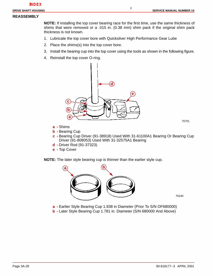
NOTE: If installing the top cover bearing race for the first time, use the same thickness ofshims that were removed or a .015 in. (0.38 mm) shim pack if the original shim packthickness is not known.
1. Lubricate the top cover bore with Quicksilver High Performance Gear Lube
2. Place the shims(s) into the top cover bore.
3. Install the bearing cup into the top cover using the tools as shown in the following figure.
4. Reinstall the top cover O-ring.
70701a
b
c
d
e
a - Shimsb - Bearing Cupc - Bearing Cup Driver (91-38918) Used With 31-61100A1 Bearing Or Bearing Cup
Driver (91-808053) Used With 31-32575A1 Bearingd - Driver Rod (91-37323)e - Top Cover
NOTE: The later style bearing cup is thinner than the earlier style cup.
75240
ba
a - Earlier Style Bearing Cup 1.938 in Diameter (Prior To S/N OF680000)b - Later Style Bearing Cup 1.781 in. Diameter (S/N 680000 And Above)

DRIVE SHAFT HOUSINGSERVICE MANUAL NUMBER 14
90-818177--3 APRIL 2001 Page 3A-29
Upper Driven Gear Subassembly
DISASSEMBLY
70124
a
a - Driven Gear Assembly
1. Clean the bearing race in the drive shaft housing and dry it thoroughly. Inspect it forexcessive pits, grooves, scores, uneven wear, discoloration due to excessive heatand/or embedded particles. Replace the bearing and the bearing cup in the drive shafthousing (explained later in this section) if any of these conditions exist.
NOTE: Disassembly of the upper driven gear assembly is for replacement of componentsonly.
2. Position the Universal Puller Plate between the driven gear and the tapered rollerbearing with the tapered side of the plate toward the roller bearing.
3. Press on the sides of plate until it bottoms out on the gear.
23265
a
c
d b
a - Universal Puller Plate (91-37241)b - Tapered Roller Bearingc - Driven Geard - Arbor Press

DRIVE SHAFT HOUSING SERVICE MANUAL NUMBER 14
Page 3A-30 90-818177--3 APRIL 2001
4. Reposition the plate and gear assembly and press the gear until the tapered rollerbearing slides off. Ensure the puller plates are aligned on the press with the threadedrods on the support brackets of the press.
23264
a
cd
b
a - Universal Puller Plate (91-37241)b - Driven Gearc - Tapered Roller Bearingd - Arbor Press
5. Reassemble the plate with the flat side of the plate toward the bearing and remove thesmall upper drive shaft tapered roller bearing using a suitable mandrel.
23265
a
b
c
d
e
a - Upper Drive Shaft Bearing (small)b - Gearc - Suitable Toold - Arbor Presse - Universal Puller Plate (91-37241)

DRIVE SHAFT HOUSINGSERVICE MANUAL NUMBER 14
90-818177--3 APRIL 2001 Page 3A-31
6. Press the driven gear from the upper drive shaft.
23266
a
b
c
d
a - Driven Gearb - Upper Drive Shaftc - Suitable Toold - Arbor Press
INSPECTION
1. Clean all parts with a suitable solvent and dry them thoroughly with compressed air. Becareful not to spin the bearing.
2. Inspect the gear for pitting, chipped or broken teeth, hairline fractures and excessive oruneven wear. Replace both the drive (pinion) and the driven gear if any of theseconditions exist.
3. Inspect the gear hub for evidence of the bearing spinning. Replace the tapered rollerbearing, the driven gear and the pinion gear on the U-joint if any evidence of spinningis found.
4. Inspect the upper drive shaft for damage, hairline fractures and evidence of the gearspinning on the shaft. Replace the upper drive shaft, the driven gear and the pinion gearon the U-joint if any of these conditions are found.
5. Inspect the upper drive shaft to ensure that the hole through the center of the shaft isclean and clear. Clean out the hole if it has any debris.

DRIVE SHAFT HOUSING SERVICE MANUAL NUMBER 14
Page 3A-32 90-818177--3 APRIL 2001
REASSEMBLY
1. Press the upper drive shaft onto the driven gear until it bottoms.
23264
ac
d
b
a - Driven Gearb - Upper Drive Shaftc - Universal Puller Plate (91-37241)d - Arbor Press
2. Press the small tapered roller bearing onto the upper drive shaft until it bottoms outon the shaft.
23264
a
cd
b
a - Tapered Roller Bearing (large)b - Driven Gearc - Suitable Tool (An Old Upper Driven Gear Bearing Inner Race)d - Arbor Press

DRIVE SHAFT HOUSINGSERVICE MANUAL NUMBER 14
90-818177--3 APRIL 2001 Page 3A-33
Drive Shaft Housing Reassembly
Drive Shaft Housing Inspection1. Inspect the locating pin holes on the drive shaft housing (at the gear housing mating
surface) to ensure that they are not elongated. Elongation of the holes may cause thedrive shaft to break because the housings may not align properly when assembled.
InstallationNOTE: If installing the upper driven gear bearing cup for the first time use the samethickness of shims that were removed or approximately a .015 in. (0.38mm) shim pack if theoriginal shim pack thickness is not known.
1. Lubricate the bore in the drive shaft housing (into which the upper driven gear bearingcup is to be installed) with Quicksilver High Performance Gear Lube.
2. Place the shim(s) into the bore of the drive shaft housing.
3. Install the upper driven gear bearing cup as shown below.
70445
ab
c
d
a - Shimsb - Bearing Cupc - Bearing Cup Driver (91-33493)d - Driver Rod (An Old Propeller Shaft Shown)
IMPORTANT: Lightly lubricate the gears, bearings, seals and O-rings withQuicksilver High Performance Gear Lube before installing. Bearings and gears mustbe lubricated to obtain accurate preload readings.
IMPORTANT: The top cover screws must be torqued to 20 lb-ft (27 Nm), to properlycheck the upper drive shaft bearing preload.

DRIVE SHAFT HOUSING SERVICE MANUAL NUMBER 14
Page 3A-34 90-818177--3 APRIL 2001
4. Lightly lubricate both of the bearings on the upper driven gear assembly with QuicksilverHigh Performance Gear Lube and install the upper driven gear assembly into the driveshaft housing.
70124
a
a - Upper Driven Gear Assembly
5. Install the top cover and torque the screws 20 lb-ft (27 Nm).
70118
a
b
a - Top Coverb - Screws (4)
DRIVE SHAFT HOUSINGSERVICE MANUAL NUMBER 14
90-818177--3 APRIL 2001 Page 3A-35
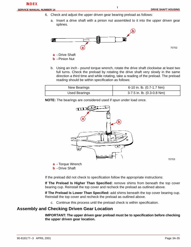
6. Check and adjust the upper driven gear bearing preload as follows:
a. Insert a drive shaft with a pinion nut assembled to it into the upper driven gearsplines.
70702a
b
a - Drive Shaftb - Pinion Nut
b. Using an inch - pound torque wrench, rotate the drive shaft clockwise at least twofull turns. Check the preload by rotating the drive shaft very slowly in the samedirection a third time and while rotating, take a reading of the preload. The preloadreading should be within specification as follows:
New Bearings 6-10 in. lb. (0.7-1.7 Nm)
Used Bearings 3-7.5 in. lb. (0.3-0.8 Nm)
NOTE: The bearings are considered used if spun under load once.
70703
ab
a - Torque Wrenchb - Drive Shaft
If the preload did not check to specification follow the appropriate instructions:
If The Preload Is Higher Than Specified: remove shims from beneath the top coverbearing cup. Reinstall the top cover and recheck the preload as outlined above.
If The Preload Is Lower Than Specified: add shims beneath the top cover bearing cup.Reinstall the top cover and recheck the preload as outlined above.
c. Continue this process until the preload check is within specification.
Assembly and Checking Driven Gear LocationIMPORTANT: The upper driven gear preload must be to specification before checkingthe upper driven gear location.

DRIVE SHAFT HOUSING SERVICE MANUAL NUMBER 14
Page 3A-36 90-818177--3 APRIL 2001
1. Install the upper driven gear shimming tool into the drive shaft housing with theappropriate opening (see chart following) toward the upper driven gear and check theupper driven gear location as follows:
1997 1/2 AND EARLIER MODELS (S/N 0K999999 AND BELOW)
Shimming Tool 91-60526
Overall Drive Unit Gear Ratio Tool Position
1.47:1, 1.50:1 Z
1.65:1 X
1.84:1 Y
1.98:1 Y
2.40:1 Y
1998 AND LATER (S/N 0L100009 AND ABOVE)
Shimming Tool 91-854377
Overall Drive Unit Gear Ratio Tool Position
1.47:1 C
1.62:1 A
1.81:1 B
1.94:1 B
2.0:1 A
2.40:1 B
IMPORTANT: The following procedure must be done exactly as stated to properlycheck the upper driven gear location.
a. Position the gear so that at least two full teeth are centered on the gauging surface.One full tooth must be on each side of the gauging surface centerline. Insert a .025in. (0.64 mm) feeler gauge between one of the teeth and the gauging surface.
b. Rotate the shimming tool until one side of the gauging surface contacts the feelergauge and a slight drag is felt on the feeler gauge.
c. Without moving the shimming tool, remove the feeler gauge and re-insert it betweenthe other tooth and the gauging surface.

DRIVE SHAFT HOUSINGSERVICE MANUAL NUMBER 14
90-818177--3 APRIL 2001 Page 3A-37
If The Feeler Gauge Can Be Inserted With Only A Slight Drag: the shimming is correct.
23012
.025”(0.64m
m)
a
Shimming Tool 91-60526
75660
B
C
A
a
Shimming Tool 91-854377a - Feeler Gauge - .025 in. (0.635 mm)

DRIVE SHAFT HOUSING SERVICE MANUAL NUMBER 14
Page 3A-38 90-818177--3 APRIL 2001
Adjusting Gear LocationIMPORTANT: If the feeler gauge can be inserted without any drag; the shimming isincorrect (the gear is to far away from the shimming tool). Repeat Steps a, b and c (aspreviously described) with progressively thicker feeler gauges until the gear locationis known.
Example: (the gear is too far away from the shimming tool) the gear location istoo low.
If feeler gauge thickness is. .30 in. 0.760 mm
Subtract specification .025 in. 0.635 mm
you get .005 in. 0.125 mm
Add this amount of shims beneath the driven gear assembly race in the drive shafthousing and subtract the same amount of shims from beneath the top cover bearingrace.
*If The Feeler Gauge Cannot Be Inserted On Both Sides Without Moving TheShimming Tool: the shimming is incorrect (the gear is too close to the shimming tool).Repeat Steps a, b and c (as described on page 3A-23) with progressively thinner feelergauges until the gear location is known.
Example: (the gear is too close to the shimming tool) the gear location is toohigh.
Specification .025 in. 0.635 mm
Subtract feeler gaugethickness:
.020 in. 0.510 mm
you get .005 in. 0.125 mm
Subtract this amount of shims beneath the upper gear assembly race in the drive shafthousing and add the same amount of shims beneath the top cover bearing race.
1. Reassemble the top cover as outlined in “Top Cover Assembly,” ‘ComponentReassembly’ section and add or subtract the appropriate quantity of shims beneath thetop cover bearing race.
2. Remove the upper driven gear assembly and remove the upper driven gear bearing cupas outlined in “Upper Driven Gear Bearing Cup,” ‘Removal’ section and add or subtractthe appropriate quantity of shims beneath the upper driven gear bearing cup race.
3. Install the upper driven gear bearing cup.
4. Install the upper driven gear assembly and recheck preload.
5. Recheck the upper driven gear location.
6. Remove the top cover and upper driven gear assembly and upper driven gear bearingcup.

DRIVE SHAFT HOUSINGSERVICE MANUAL NUMBER 14
90-818177--3 APRIL 2001 Page 3A-39
Seal Installation1. Lightly oil the bore with Quicksilver High Performance Gear Lube.
2. Assemble the first seal to the long end of the driver tool with the lip (spring) side facingaway from the driver shoulder and press the seal into the bore.
70705a
b
c
a - Oil Seal (Lip Down)b - Drive Tool (91-817570) (Long End)c - Driver Rod (91-37323)
3. Lightly oil the bore again with Quicksilver High Performance Gear Lube.
4. Assemble the second seal to the short end of the driver tool with the lip (spring) sidefacing toward the driver shoulder and press the seal into the bore.
70706ab
c
a - Oil Seal (Lip Up)b - Drive Tool (91-817570) (Short End)c - Driver Rod (91-37323)

DRIVE SHAFT HOUSING SERVICE MANUAL NUMBER 14
Page 3A-40 90-818177--3 APRIL 2001
5. Reinstall the driven gear bearing cup and shims.
70445
ab
c
d
a - Shimsb - Bearing Cupc - Bearing Cup Driver (91-33493)d - Driver Rod (An Old Propeller Shaft Shown)
6. Completely fill the space between the two seals with 2-4-C Marine Lubricant with Teflonand install the upper driven gear assembly. Do not install the top cover at this time.
70124
a
a - Upper Driven Gear Assembly
NOTE: Install the same thickness of shims as were originally removed during disassembly.If original shim thickness is not known, start with approximately a .015 in. (0.38 mm) shimpack.

DRIVE SHAFT HOUSINGSERVICE MANUAL NUMBER 14
90-818177--3 APRIL 2001 Page 3A-41
7. Place the spacer ring into the drive shaft housing U-joint bore and place the shims(s)into the bore.
70123
a
b
a - Spacer Ring (Installed First)b - Shims
8. Lightly lubricate the drive shaft housing U-joint bore with Quicksilver High PerformanceGear Lube.
9. Thoroughly lubricate the U-joint retainer threads on the U-joint retainer (not in the driveshaft housing bore) with Quicksilver Special Lubricant 101.
10. Install the U-joint assembly straight into the drive shaft housing and screw down theretainer using the following procedure.
70122
a
a - U-joint Assembly
NOTE: The torque wrench reading will be less than the actual torque being applied to theretainer, due to the torque reading being taken through the retainer wrench. Use thefollowing procedure to torque the retainer to 200 lb-ft (271 Nm).

DRIVE SHAFT HOUSING SERVICE MANUAL NUMBER 14
Page 3A-42 90-818177--3 APRIL 2001
11. Measure the length of the torque wrench as follows:
a. On beam type torque wrenches, measure from the square drive to the fulcrum (pivot)point of the handle.
b. On click-stop or dial type torque wrenches, measure from the square drive to thereference mark on the handle (marked with 2 bands, a line, etc.).
12. Use the following chart to determine the torque wrench reading required to properlytorque the retainer to 200 lb-ft (271 Nm).
Torque Wrench Length In Inches (cm) Torque Wrench Reading, in lb-ft (Nm) toachieve 200 lb-ft (271 Nm) of torque
15 (38) 111 (151)
16 (41) 114 (155)
17 (43) 117 (159)
18 (46) 120 (163)
19 (48) 123 (167)
20 (51) 125 (170)
21 (53) 127 (172)
22 (56) 129 (175)
23 (58) 131 (178)
24 (61) 133 (180)
25 (64) 135 (183)
26 (66) 136 (184)
27 (69) 138 (187)
28 (71) 140 (190)
29 (74) 141 (191)
30 (76) 143 (194)
31 (79) 144 (195)
32 (81) 145 (197)
33 (84) 147 (200)
34 (86) 148 (201)
35 (89) 149 (202)
36 (91) 150 (203)
26363
a b
a - Torque Wrench Lengthb - 12 in. retainer Wrench
a. Torque the retainer until the torque reading for your length of torque wrench isattained.

DRIVE SHAFT HOUSINGSERVICE MANUAL NUMBER 14
90-818177--3 APRIL 2001 Page 3A-43
Checking and Adjusting Drive Gear Location1. Install the drive gear shimming tool into the drive shaft housing with the appropriate
opening (see chart following) toward the drive gear. Check the gear location as follows:
Shimming Tool 91-60523
Overall Drive Unit Gear Ratio Tool Position
1.47 or 1.50:1 Z
1.62 or 1.65:1 Y
1.81 or 1.84:1 Y
1.94 or 1.98:1 Y
2.0:1 Y
2.40:1 Y
IMPORTANT: The following procedure must be done exactly as stated to properlycheck the upper driven gear location.
a. Position the gear so that at least two full teeth are centered on the gauging surface.One full tooth must be on each side of the gauging surface centerline. Insert a .025in. (0.64 mm) feeler gauge between one of the teeth and the gauging surface.
b. Rotate the shimming tool until one side of the gauging surface contacts the feelergauge and a slight drag is felt on the feeler gauge.
c. Without moving the shimming tool, remove the feeler gauge and re-insert it betweenthe other tooth and the gauging surface.
NOTE: If the feeler gauge can be inserted with only a slight drag: the shimming iscorrect (the gear is the correct distance from the shimming tool).
23012
a
b
a - Feeler Gaugeb - Shimming Tool
DRIVE SHAFT HOUSING SERVICE MANUAL NUMBER 14
Page 3A-44 90-818177--3 APRIL 2001
ADJUSTING PINION GEAR LOCATION (U-JOINT ASSEMBLY)
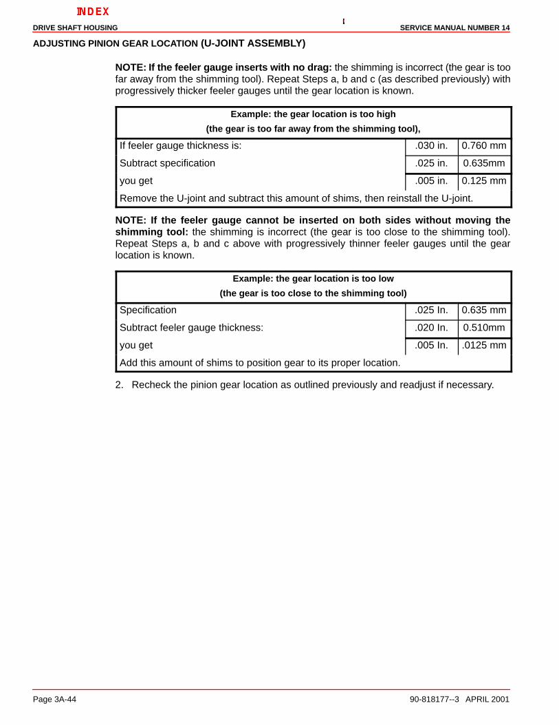
NOTE: If the feeler gauge inserts with no drag: the shimming is incorrect (the gear is toofar away from the shimming tool). Repeat Steps a, b and c (as described previously) withprogressively thicker feeler gauges until the gear location is known.
Example: the gear location is too high
(the gear is too far away from the shimming tool),
If feeler gauge thickness is: .030 in. 0.760 mm
Subtract specification .025 in. 0.635mm
you get .005 in. 0.125 mm
Remove the U-joint and subtract this amount of shims, then reinstall the U-joint.
NOTE: If the feeler gauge cannot be inserted on both sides without moving theshimming tool: the shimming is incorrect (the gear is too close to the shimming tool).Repeat Steps a, b and c above with progressively thinner feeler gauges until the gearlocation is known.
Example: the gear location is too low
(the gear is too close to the shimming tool)
Specification .025 In. 0.635 mm
Subtract feeler gauge thickness: .020 In. 0.510mm
you get .005 In. .0125 mm
Add this amount of shims to position gear to its proper location.
2. Recheck the pinion gear location as outlined previously and readjust if necessary.

DRIVE SHAFT HOUSINGSERVICE MANUAL NUMBER 14
90-818177--3 APRIL 2001 Page 3A-45
Final Reassembly
1. Assemble the O-ring to the top cover.
2. Apply Quicksilver Perfect Seal to the top cover (or the drive shaft housing) in the areahighlighted in the next figure.
70725
a
b
c
a - Top Coverb - O-ringc - Quicksilver Perfect Seal
3. Install the top cover and torque the screws to 20 lb-ft (27 Nm).
70118
a
b
a - Top Coverb - Screws

DRIVE SHAFT HOUSING SERVICE MANUAL NUMBER 14
Page 3A-46 90-818177--3 APRIL 2001
4. Install the rubber seal into the drive shaft housing.
70125
a
b
a - Rubber Sealb - Drive Shaft Housing
5. Lubricate the end of the water tube (that goes into the drive shaft housing) withQuicksilver 2-4-C Marine Lubricant with Teflon. Install the water tube into the rubber sealin the drive shaft housing. Make sure that the tube is positioned with the bend towardsthe forward end of the unit and the longest straight section toward the gear housingmating surface.
70126
a
b
a - Water Tube (Correctly Positioned)b - Drive Shaft Housing

DRIVE SHAFT HOUSINGSERVICE MANUAL NUMBER 14
90-818177--3 APRIL 2001 Page 3A-47
Joining Drive Shaft Housing/Gear Housing1. Lubricate the end of the water tube (in the drive shaft housing) and the splines of the
drive shaft with Quicksilver 2-4-C Marine Lubricant with Teflon.
NOTE: The aluminum dam in the gear housing has been changed to a rubber filler plug. Ifthe aluminum water pump dam in the gear housing has become corroded or damaged, itcan be replaced with the rubber filler plug.
IMPORTANT: Ensure that the drain hole of the aluminum water pump dam is notclogged with any foreign material. Damage may occur if passage is blocked.
71410 71436
ac
b
a - Aluminum Damb - Rubber Filler Plugc - Drain Hole
2. Units with an aluminum dam require a bead of Permatex Ultra Blue Silicone Sealantalong the top of the dam. If rubber filler plug is present, it is not necessary to use thissealant.
3. To replace the aluminum dam if it has been removed and undamaged, place a bead ofPermatex Ultra Blue Silicone Sealant down both sides of it.
4. Ensure that the water pump dam in the drive shaft housing is present and installedcorrectly. Ensure that all parts are present on the gear housing and the drive shafthousing.
IMPORTANT: Install the Trim Tab (or Anodic plate) bolt into the gear housing.
70710
a
bc
a - Drive Shaft Splinesb - Sealant - Aluminum Dam Onlyc - Trim Tab Bolt
5. Position the drive shaft housing straight above the gear housing. Align the water tubesleeve with the water tube and the drive shaft with the upper drive gear and assemblethe drive shaft housing to the gear housing. It may be necessary to rotate the propellershaft or the U-joint to align the drive shaft splines with the upper drive gear splines.

DRIVE SHAFT HOUSING SERVICE MANUAL NUMBER 14
Page 3A-48 90-818177--3 APRIL 2001
6. Assemble the front nut to the front stud of the unit.
7. Assemble the aft screw into the forward hole in the trim tab well of the gear housing.
8. Assemble the bolts, nuts and washers to the port and starboard sides of the unit.
70117
b
c
a
a - Nuts, Bolts, Washersb - Nutc - Screw
9. Assemble the trim tab (or anodic plate) and align it to the mark made previously on thegear housing. Torque the screw to 23 lb-ft (31 Nm).
10. Position drive unit so anti-ventilation plate is level.
11. Refill drive unit with gear lube. Refer to Section 1B.

DRIVE SHAFT HOUSINGSERVICE MANUAL NUMBER 14
90-818177--3 APRIL 2001 Page 3A-49
THIS PAGE IS INTENTIONALLY BLANK

DRIVE SHAFT HOUSING SERVICE MANUAL NUMBER 14
Page 3A-50 90-818177--3 APRIL 2001
THIS PAGE IS INTENTIONALLY BLANK


![POWER DRIVE PTO DRIVE SHAFT SERIES P 300 – … · power drive pto drive shaft series p 300 ... power drive pto drive shaft series with full guard and without ... (inlb) p [kw] (hp)](https://static.fdocuments.us/doc/165x107/5b5ca9cb7f8b9a3a718cbcff/power-drive-pto-drive-shaft-series-p-300-power-drive-pto-drive-shaft-series.jpg)