SERVICE MANUAL - audiolabga.com I.pdf · Klipsch Subwoofer Amplifier Service Manual KSAMM-002a...
21
SERVICE MANUAL Subwoofer Amplifier Model: SW12-I SW15-I KLIPSCH, INC.
Transcript of SERVICE MANUAL - audiolabga.com I.pdf · Klipsch Subwoofer Amplifier Service Manual KSAMM-002a...
SERVICE MANUAL
Subwoofer Amplifier Model: SW12-ISW15-I
KLIPSCH, INC.
Klipsch Subwoofer Amplifier Service Manual KSAMM-002a
TABLE OF CONTENTS
SPECIFICATIONS.......................................................................................................................................2
Model: SW12-I ...........................................................................................................................................2Model: SW15-I ...........................................................................................................................................2
THEORY OF OPERATION....................................................................................................................... 3
INPUTS ...................................................................................................................................................... 3SIGNAL CONDITIONING ......................................................................................................................... 3COMPRESSION......................................................................................................................................... 3DRIVER CIRCUIT ..................................................................................................................................... 3OUTPUT .................................................................................................................................................... 3OTHER FEATURES................................................................................................................................... 4
ALIGNMENT PROCEDURES .................................................................................................................. 5
Model: SW12-I .......................................................................................................................................... 5Model: SW15-I .......................................................................................................................................... 6
TROUBLE SHOOTING GUIDE................................................................................................................ 7
SW12 PARTS LIST...................................................................................................................................... 9
SW15 PARTS LIST.................................................................................................................................... 12
SCHEMATICS ........................................................................................................................................... 15
Model: SW12-I ........................................................................................................................................ 15Model: SW15-I ........................................................................................................................................ 18
Page 1
Klipsch Subwoofer Amplifier Service Manual KSAMM-002a
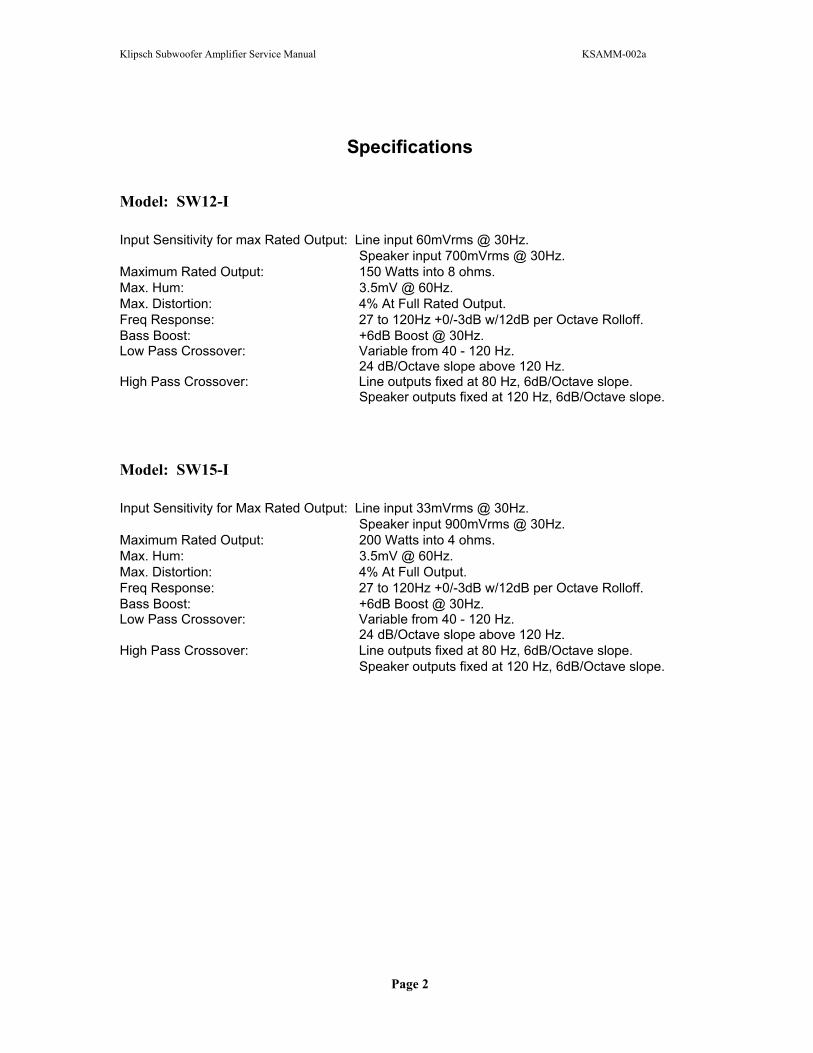
Specifications
Model: SW12-I
Input Sensitivity for max Rated Output: Line input 60mVrms @ 30Hz. Speaker input 700mVrms @ 30Hz.Maximum Rated Output: 150 Watts into 8 ohms. Max. Hum: 3.5mV @ 60Hz.Max. Distortion: 4% At Full Rated Output. Freq Response: 27 to 120Hz +0/-3dB w/12dB per Octave Rolloff. Bass Boost: +6dB Boost @ 30Hz. Low Pass Crossover: Variable from 40 - 120 Hz. 24 dB/Octave slope above 120 Hz.High Pass Crossover: Line outputs fixed at 80 Hz, 6dB/Octave slope. Speaker outputs fixed at 120 Hz, 6dB/Octave slope.
Model: SW15-I
Input Sensitivity for Max Rated Output: Line input 33mVrms @ 30Hz. Speaker input 900mVrms @ 30Hz.Maximum Rated Output: 200 Watts into 4 ohms. Max. Hum: 3.5mV @ 60Hz.Max. Distortion: 4% At Full Output. Freq Response: 27 to 120Hz +0/-3dB w/12dB per Octave Rolloff. Bass Boost: +6dB Boost @ 30Hz. Low Pass Crossover: Variable from 40 - 120 Hz. 24 dB/Octave slope above 120 Hz.High Pass Crossover: Line outputs fixed at 80 Hz, 6dB/Octave slope. Speaker outputs fixed at 120 Hz, 6dB/Octave slope.
Page 2
Klipsch Subwoofer Amplifier Service Manual KSAMM-002a
THEORY OF OPERATION
SW12, & SW15 Series I Amplifiers
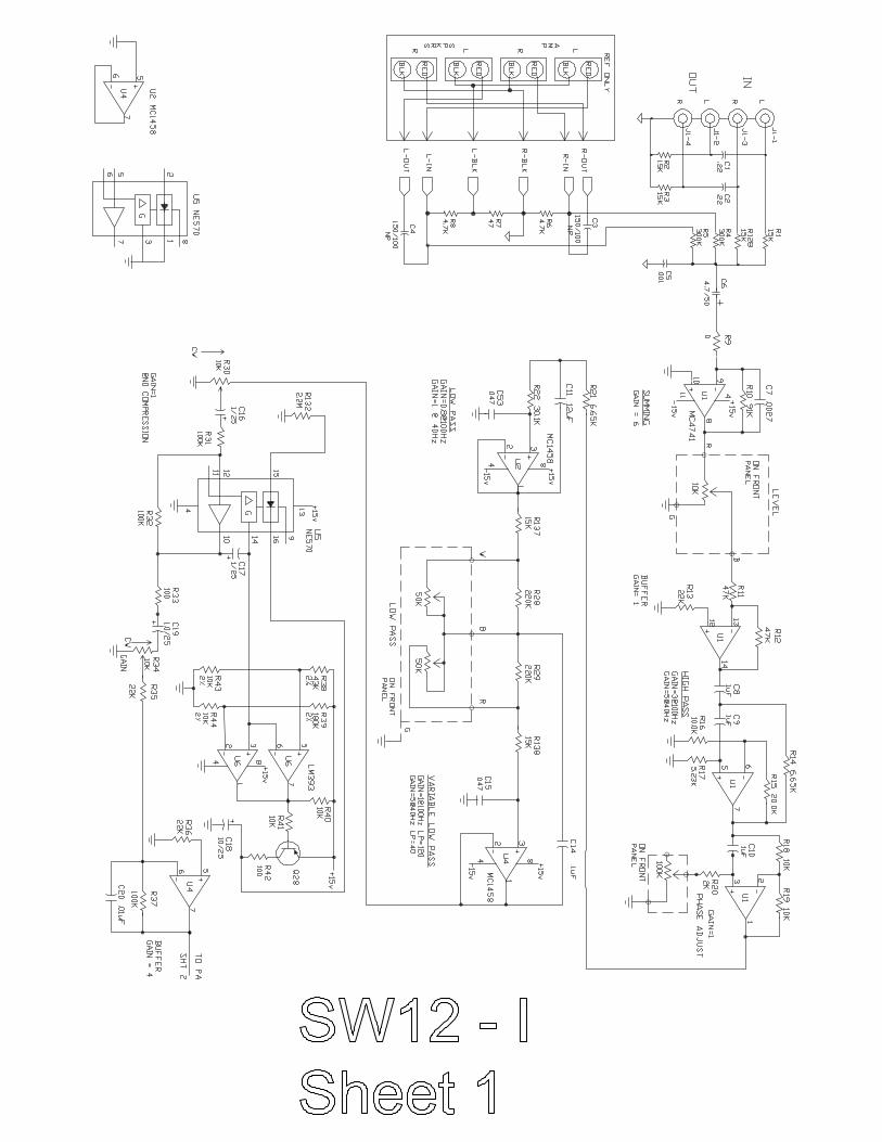
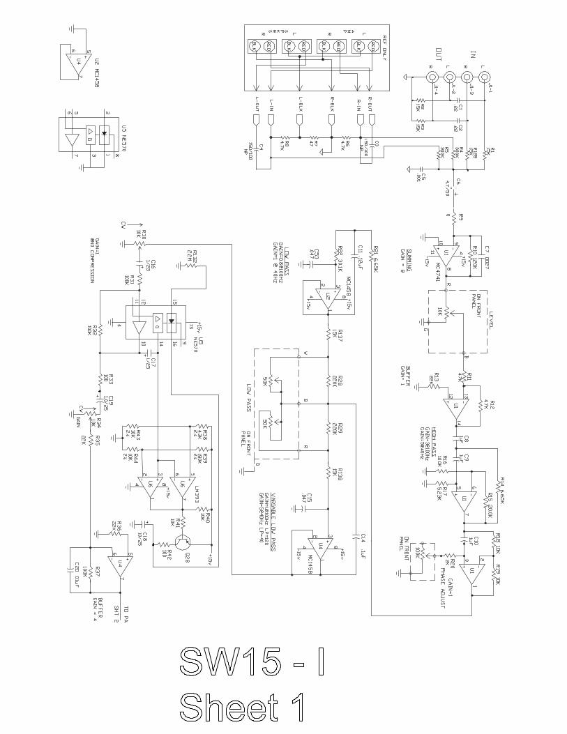
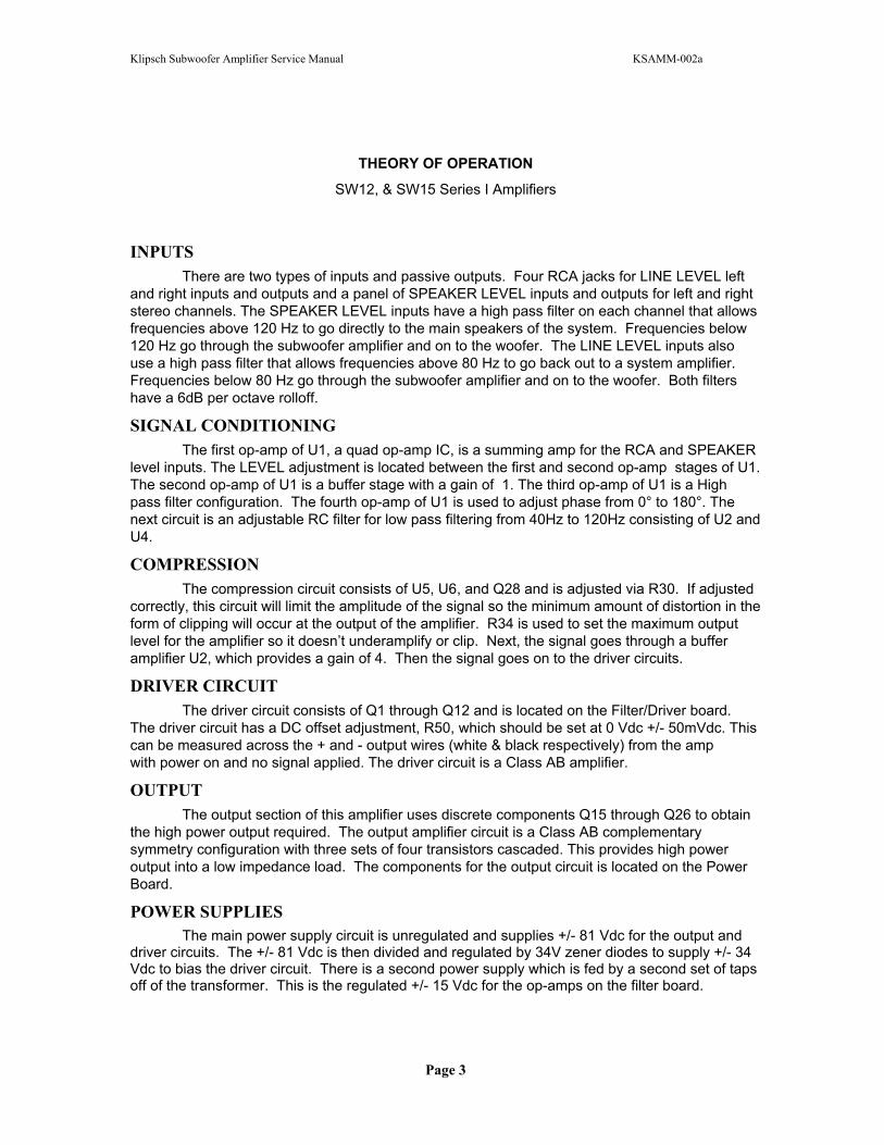
INPUTSThere are two types of inputs and passive outputs. Four RCA jacks for LINE LEVEL left
and right inputs and outputs and a panel of SPEAKER LEVEL inputs and outputs for left and right stereo channels. The SPEAKER LEVEL inputs have a high pass filter on each channel that allows frequencies above 120 Hz to go directly to the main speakers of the system. Frequencies below 120 Hz go through the subwoofer amplifier and on to the woofer. The LINE LEVEL inputs also use a high pass filter that allows frequencies above 80 Hz to go back out to a system amplifier.Frequencies below 80 Hz go through the subwoofer amplifier and on to the woofer. Both filters have a 6dB per octave rolloff.
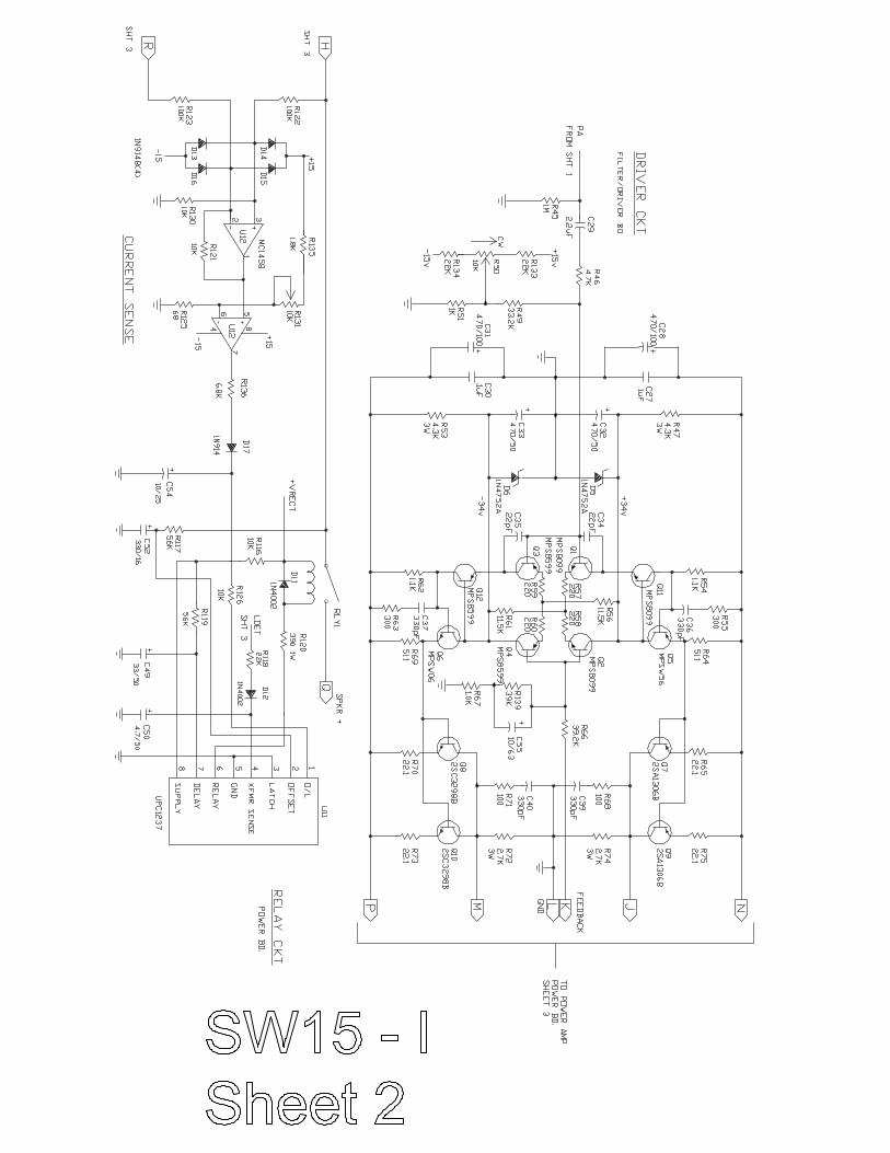
SIGNAL CONDITIONING The first op-amp of U1, a quad op-amp IC, is a summing amp for the RCA and SPEAKER
level inputs. The LEVEL adjustment is located between the first and second op-amp stages of U1. The second op-amp of U1 is a buffer stage with a gain of 1. The third op-amp of U1 is a High pass filter configuration. The fourth op-amp of U1 is used to adjust phase from 0° to 180°. The next circuit is an adjustable RC filter for low pass filtering from 40Hz to 120Hz consisting of U2 and U4.
COMPRESSIONThe compression circuit consists of U5, U6, and Q28 and is adjusted via R30. If adjusted
correctly, this circuit will limit the amplitude of the signal so the minimum amount of distortion in the form of clipping will occur at the output of the amplifier. R34 is used to set the maximum output level for the amplifier so it doesn’t underamplify or clip. Next, the signal goes through a buffer amplifier U2, which provides a gain of 4. Then the signal goes on to the driver circuits.
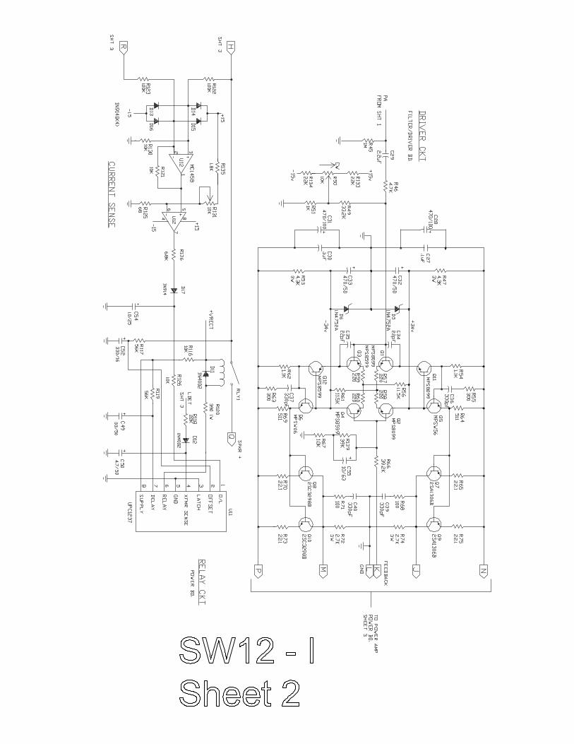
DRIVER CIRCUIT The driver circuit consists of Q1 through Q12 and is located on the Filter/Driver board.
The driver circuit has a DC offset adjustment, R50, which should be set at 0 Vdc +/- 50mVdc. This can be measured across the + and - output wires (white & black respectively) from the amp with power on and no signal applied. The driver circuit is a Class AB amplifier.
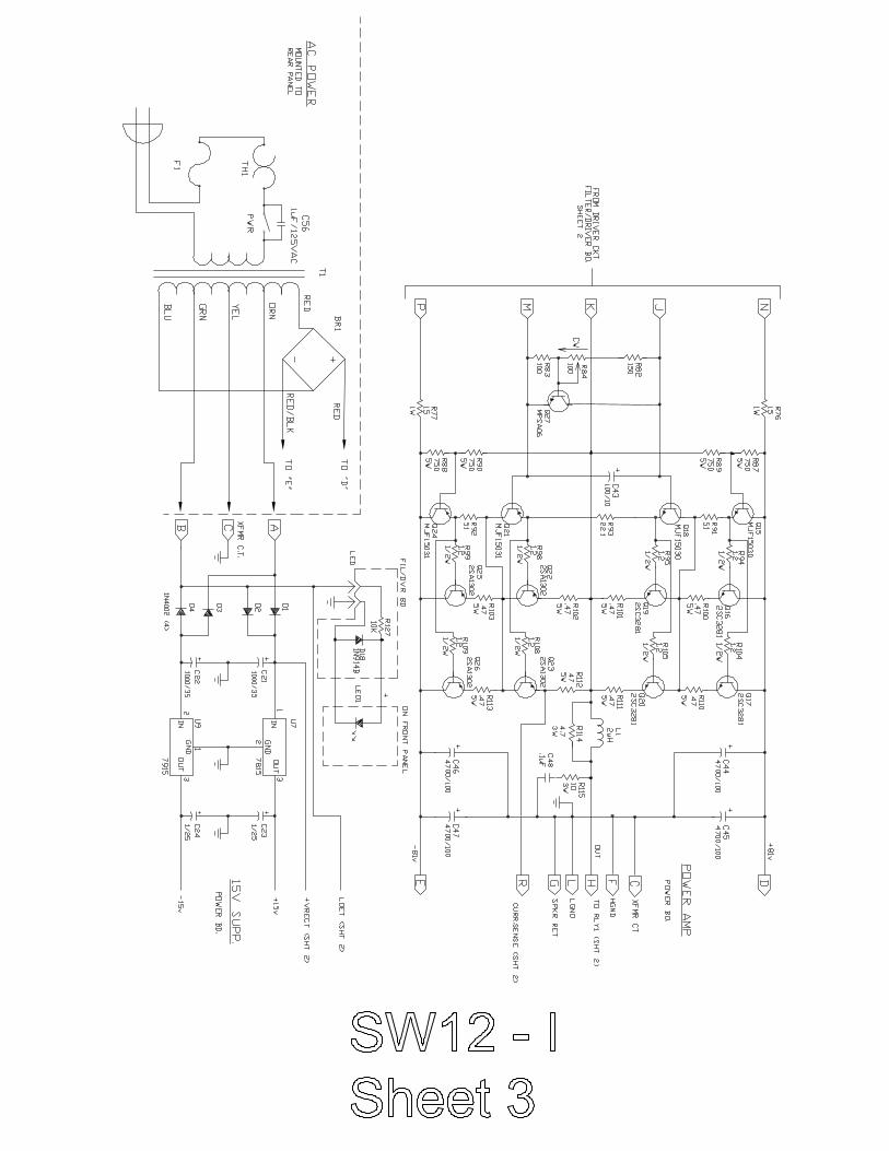
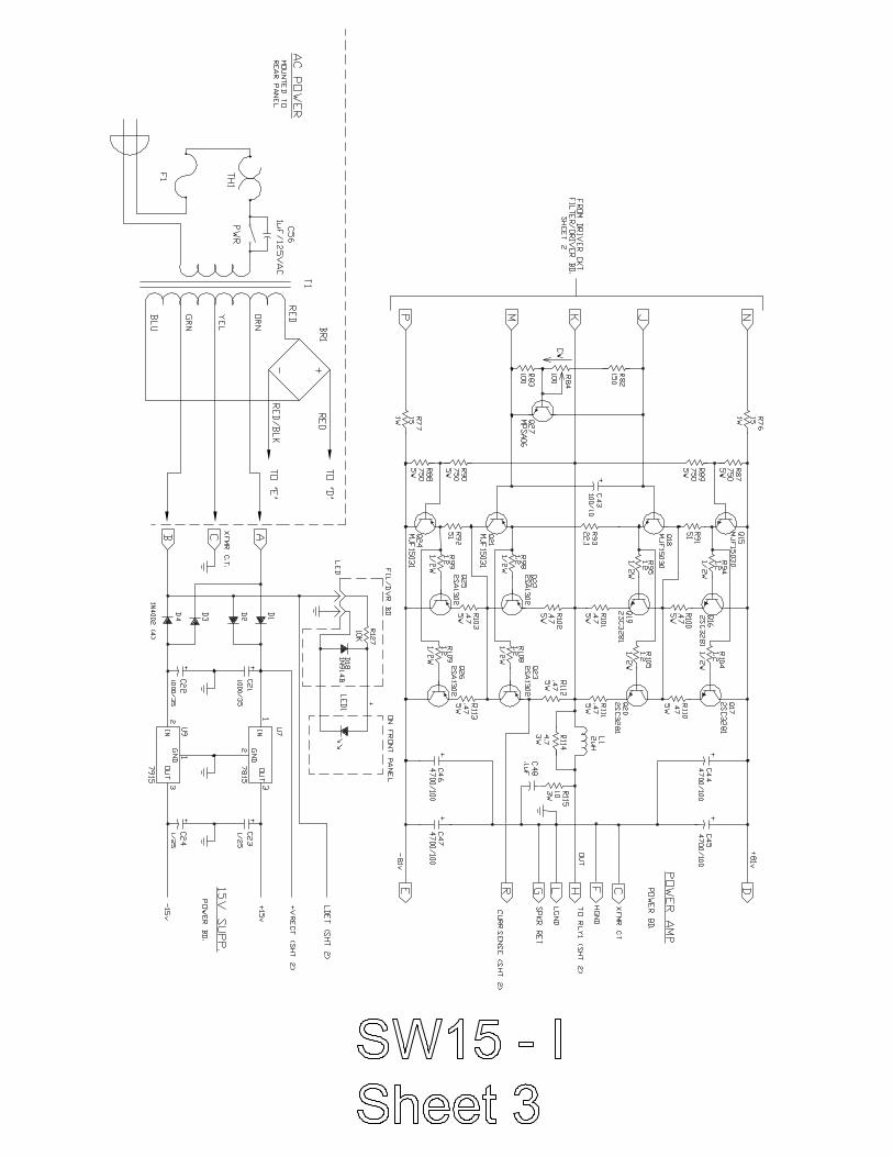
OUTPUTThe output section of this amplifier uses discrete components Q15 through Q26 to obtain
the high power output required. The output amplifier circuit is a Class AB complementary symmetry configuration with three sets of four transistors cascaded. This provides high power output into a low impedance load. The components for the output circuit is located on the Power Board.
POWER SUPPLIES The main power supply circuit is unregulated and supplies +/- 81 Vdc for the output and
driver circuits. The +/- 81 Vdc is then divided and regulated by 34V zener diodes to supply +/- 34 Vdc to bias the driver circuit. There is a second power supply which is fed by a second set of taps off of the transformer. This is the regulated +/- 15 Vdc for the op-amps on the filter board.
Page 3

Klipsch Subwoofer Amplifier Service Manual KSAMM-002a
OTHER FEATURES This amplifier uses a control circuit to control the operation of the output relay. When
power is first applied the circuit provides a delay before activating the relay. This is a protection feature to protect the speaker and amplifier from initial current surges. The circuit also provides protection from over-current conditions by de-activating the relay when excessive output current is sensed. The relay and it’s control circuitry is located on the Filter/Driver Board and consists of U11, U12, RLY 1 and R131. R131 is used to set the threshold level for over-current sensing.
Page 4
Klipsch Subwoofer Amplifier Service Manual KSAMM-002a
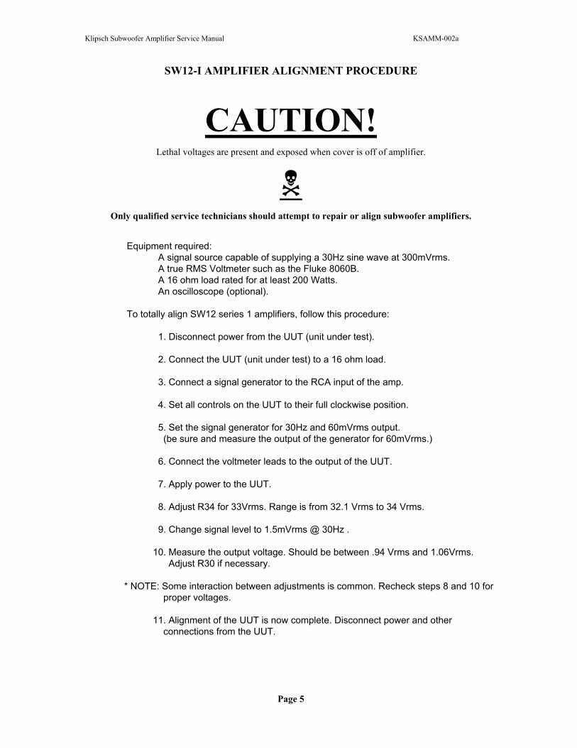
SW12-I AMPLIFIER ALIGNMENT PROCEDURE
CAUTION!Lethal voltages are present and exposed when cover is off of amplifier.
Only qualified service technicians should attempt to repair or align subwoofer amplifiers.
Equipment required: A signal source capable of supplying a 30Hz sine wave at 300mVrms. A true RMS Voltmeter such as the Fluke 8060B. A 16 ohm load rated for at least 200 Watts. An oscilloscope (optional).
To totally align SW12 series 1 amplifiers, follow this procedure:
1. Disconnect power from the UUT (unit under test).
2. Connect the UUT (unit under test) to a 16 ohm load.
3. Connect a signal generator to the RCA input of the amp.
4. Set all controls on the UUT to their full clockwise position.
5. Set the signal generator for 30Hz and 60mVrms output. (be sure and measure the output of the generator for 60mVrms.)
6. Connect the voltmeter leads to the output of the UUT.
7. Apply power to the UUT.
8. Adjust R34 for 33Vrms. Range is from 32.1 Vrms to 34 Vrms.
9. Change signal level to 1.5mVrms @ 30Hz .
10. Measure the output voltage. Should be between .94 Vrms and 1.06Vrms. Adjust R30 if necessary.
* NOTE: Some interaction between adjustments is common. Recheck steps 8 and 10 for proper voltages.
11. Alignment of the UUT is now complete. Disconnect power and other connections from the UUT.
Page 5
Klipsch Subwoofer Amplifier Service Manual KSAMM-002a
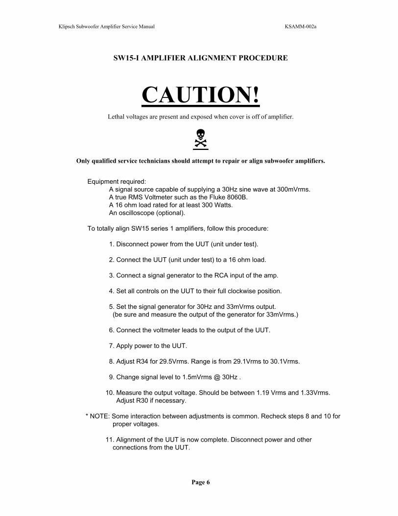
SW15-I AMPLIFIER ALIGNMENT PROCEDURE
CAUTION!Lethal voltages are present and exposed when cover is off of amplifier.
Only qualified service technicians should attempt to repair or align subwoofer amplifiers.
Equipment required: A signal source capable of supplying a 30Hz sine wave at 300mVrms. A true RMS Voltmeter such as the Fluke 8060B. A 16 ohm load rated for at least 300 Watts. An oscilloscope (optional).
To totally align SW15 series 1 amplifiers, follow this procedure:
1. Disconnect power from the UUT (unit under test).
2. Connect the UUT (unit under test) to a 16 ohm load.
3. Connect a signal generator to the RCA input of the amp.
4. Set all controls on the UUT to their full clockwise position.
5. Set the signal generator for 30Hz and 33mVrms output. (be sure and measure the output of the generator for 33mVrms.)
6. Connect the voltmeter leads to the output of the UUT.
7. Apply power to the UUT.
8. Adjust R34 for 29.5Vrms. Range is from 29.1Vrms to 30.1Vrms.
9. Change signal level to 1.5mVrms @ 30Hz .
10. Measure the output voltage. Should be between 1.19 Vrms and 1.33Vrms. Adjust R30 if necessary.
* NOTE: Some interaction between adjustments is common. Recheck steps 8 and 10 for proper voltages.
11. Alignment of the UUT is now complete. Disconnect power and other connections from the UUT.
Page 6
Klipsch Subwoofer Amplifier Service Manual KSAMM-002a
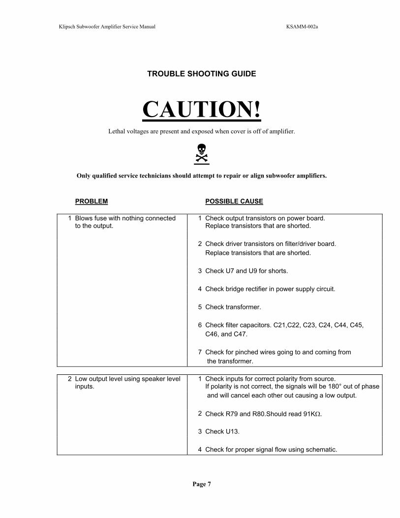
TROUBLE SHOOTING GUIDE
CAUTION!Lethal voltages are present and exposed when cover is off of amplifier.
Only qualified service technicians should attempt to repair or align subwoofer amplifiers.
PROBLEM POSSIBLE CAUSE
1 Blows fuse with nothing connected 1 Check output transistors on power board. to the output. Replace transistors that are shorted.
2 Check driver transistors on filter/driver board.Replace transistors that are shorted.
3 Check U7 and U9 for shorts.
4 Check bridge rectifier in power supply circuit.
5 Check transformer.
6 Check filter capacitors. C21,C22, C23, C24, C44, C45, C46, and C47.
7 Check for pinched wires going to and coming from the transformer.
2 Low output level using speaker level 1 Check inputs for correct polarity from source.inputs. If polarity is not correct, the signals will be 180° out of phase
and will cancel each other out causing a low output.
2 Check R79 and R80.Should read 91K .
3 Check U13.
4 Check for proper signal flow using schematic.
Page 7
Klipsch Subwoofer Amplifier Service Manual KSAMM-002a
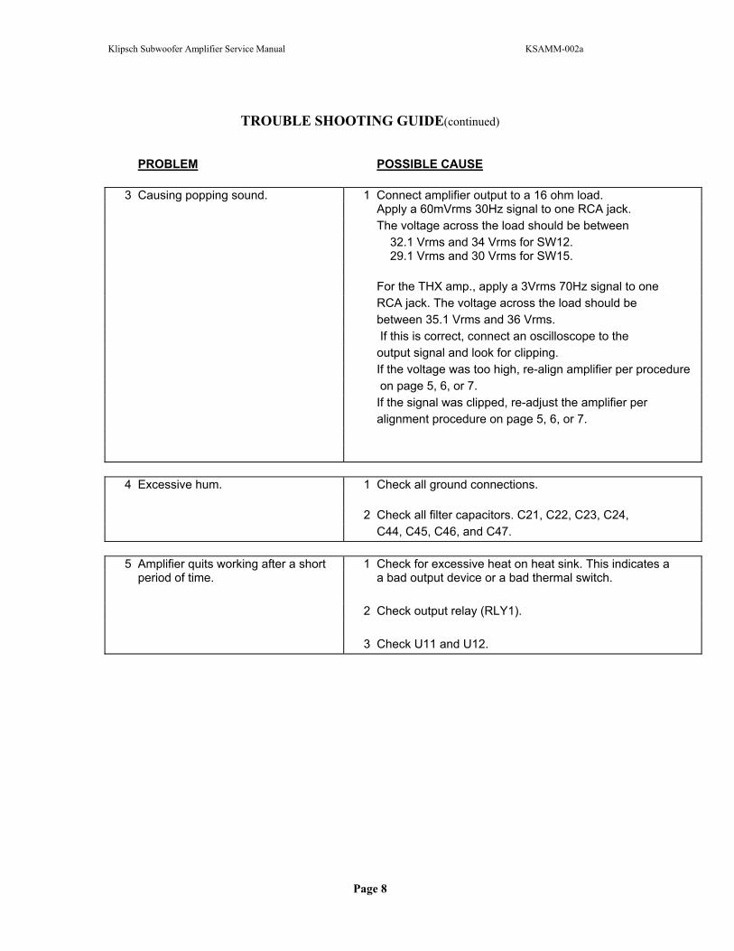
TROUBLE SHOOTING GUIDE(continued)
PROBLEM POSSIBLE CAUSE
3 Causing popping sound. 1 Connect amplifier output to a 16 ohm load.Apply a 60mVrms 30Hz signal to one RCA jack.The voltage across the load should be between 32.1 Vrms and 34 Vrms for SW12. 29.1 Vrms and 30 Vrms for SW15.
For the THX amp., apply a 3Vrms 70Hz signal to one RCA jack. The voltage across the load should be between 35.1 Vrms and 36 Vrms. If this is correct, connect an oscilloscope to theoutput signal and look for clipping.If the voltage was too high, re-align amplifier per procedure on page 5, 6, or 7.If the signal was clipped, re-adjust the amplifier peralignment procedure on page 5, 6, or 7.
4 Excessive hum. 1 Check all ground connections.
2 Check all filter capacitors. C21, C22, C23, C24,C44, C45, C46, and C47.
5 Amplifier quits working after a short 1 Check for excessive heat on heat sink. This indicates a period of time. a bad output device or a bad thermal switch.
2 Check output relay (RLY1).
3 Check U11 and U12.
Page 8

Klipsch Subwoofer Amplifier Service Manual KSAMM-002a
SW12-I PARTS LISTPART VALUE/PART NUMBER KLIPSCH PART #LEVEL CONTROL 10K VARIABLELOWPASS ADJUST 50K VARIABLE, DUALPHASE ADJUST 100K VARIABLER1, R2, R3, R128, R137, R138 15KR12, R11 47KR13, R35, R36, R133, R134 22KR132 2.2 MegR139 39KR14, R21 6.65KR15 20KR16, R18, R19, R40, R41, R127 10KR17 5.23KR20 2KR22 30.1KR28, R29 220KR30, R34, R50 10K VARIABLER31, R32, R37 100KR33, R42, R68, R71 100R38 43K 2%R39 180K 2%R43, R44 10K 2%R6, R8, R46 4.7KR47, R53 4.3K 3WATTR9 0R49 33.2KR51, R67 1KR54, R62 1.1KR55, R63 300R56, R61 11.5KR57, R58, R59, R60 220R6, R8 510 2WATTR64, R69 511R65, R70, R73, R75 22.1R66 39.2KR72, R74 2.7K 3WATTR10 91KR45 1MR7 47R4, R5 300KC1, C2 .22µFC10, C27, C30 .1µFC11 .12µFC15, C53 .047µFC16, C17, C19 1µF 25V ElectrolyticC20 .01µFC5 .001µFC29 2.2µFC3, C4 150µF 100V NON-POLARC32, C33 470µF 50V ElectrolyticC34, C35 22pF
Page 9
Klipsch Subwoofer Amplifier Service Manual KSAMM-002a
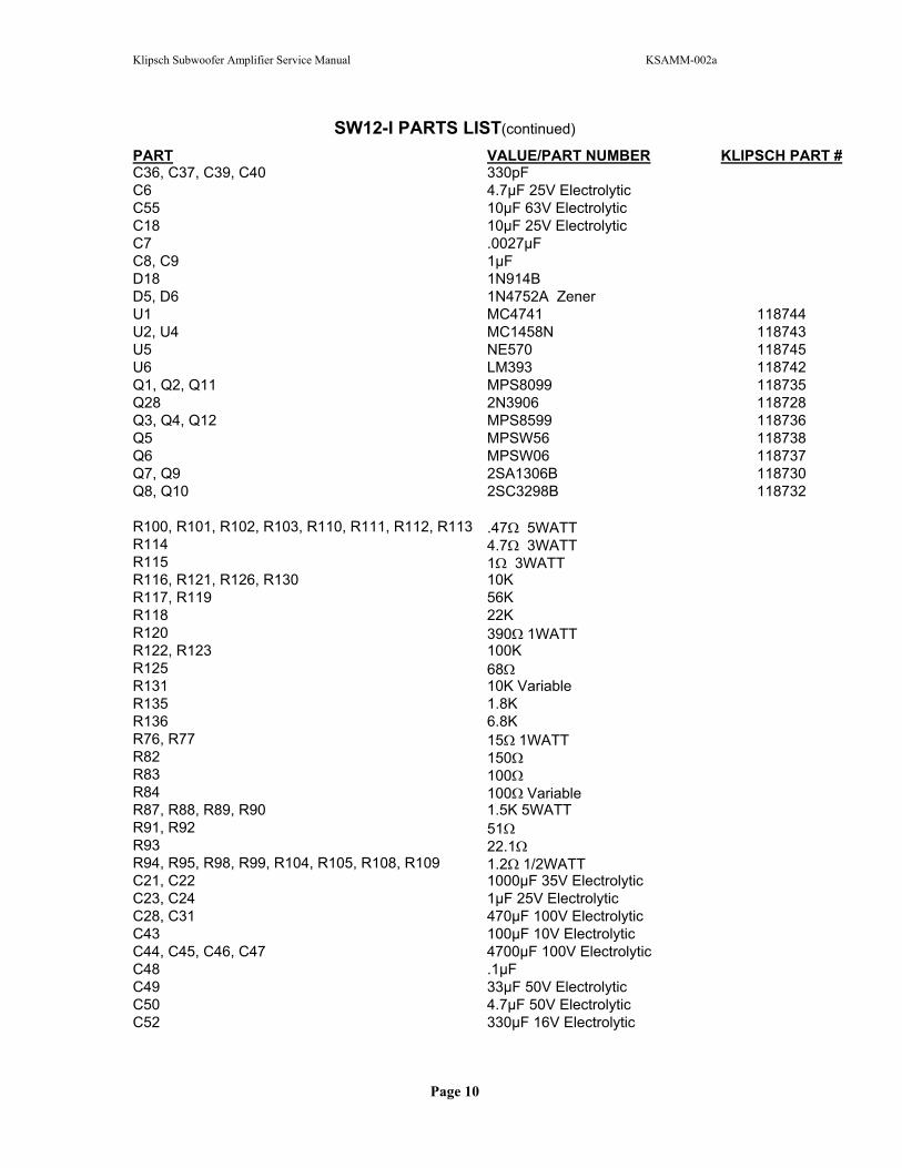
SW12-I PARTS LIST(continued)
PART VALUE/PART NUMBER KLIPSCH PART #C36, C37, C39, C40 330pFC6 4.7µF 25V ElectrolyticC55 10µF 63V ElectrolyticC18 10µF 25V ElectrolyticC7 .0027µFC8, C9 1µFD18 1N914BD5, D6 1N4752A ZenerU1 MC4741 118744U2, U4 MC1458N 118743U5 NE570 118745U6 LM393 118742Q1, Q2, Q11 MPS8099 118735Q28 2N3906 118728Q3, Q4, Q12 MPS8599 118736Q5 MPSW56 118738Q6 MPSW06 118737Q7, Q9 2SA1306B 118730Q8, Q10 2SC3298B 118732
R100, R101, R102, R103, R110, R111, R112, R113 .47 5WATTR114 4.7 3WATTR115 1 3WATTR116, R121, R126, R130 10KR117, R119 56KR118 22KR120 390 1WATTR122, R123 100KR125 68R131 10K VariableR135 1.8KR136 6.8KR76, R77 15 1WATTR82 150R83 100R84 100 VariableR87, R88, R89, R90 1.5K 5WATTR91, R92 51R93 22.1R94, R95, R98, R99, R104, R105, R108, R109 1.2 1/2WATTC21, C22 1000µF 35V ElectrolyticC23, C24 1µF 25V ElectrolyticC28, C31 470µF 100V ElectrolyticC43 100µF 10V ElectrolyticC44, C45, C46, C47 4700µF 100V ElectrolyticC48 .1µFC49 33µF 50V ElectrolyticC50 4.7µF 50V ElectrolyticC52 330µF 16V Electrolytic
Page 10

Klipsch Subwoofer Amplifier Service Manual KSAMM-002a
SW12-I PARTS LIST(continued)
PART VALUE/PART NUMBER KLIPSCH PART #C54 10µF 25V ElectrolyticC56 .1µF 125VacD1, D2, D3, D4, D11, D12 1N4002D13, D14, D15, D16, D17 1N914Q15, Q18 MJF15030 118733Q16, Q17, Q19, Q20 2SC3281 118731Q21, Q24 MJF15031 118734Q22, Q23, Q25, Q26 2SA1302 118729Q27 MPSA06U11 UPC1237 118746U12 MC1458 118743U7 7815 118739U9 7915 118740L1 2µHF2, F3 JUMPERRLY1 AROMAT J51E-12 (Relay)RCA PANEL SPEAKER INPUT JACKSTRANSFORMER PW-6582 118721SW2 (Power) F1 5 Amp 250Vac Slow Blow 118348TH1 (Thermal protection) ASAH US-602SBR1 GBPC 3502DUAL VOLTAGE TRANSFORMER PW-6661 118725DUAL VOLTAGE SWITCH 115 to 230CAPACITOR (DUAL VOLTAGE MODEL) .047µF 300V
Page 11
Klipsch Subwoofer Amplifier Service Manual KSAMM-002a
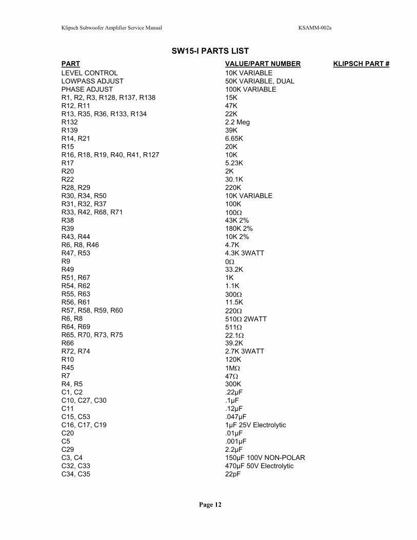
SW15-I PARTS LISTPART VALUE/PART NUMBER KLIPSCH PART #LEVEL CONTROL 10K VARIABLELOWPASS ADJUST 50K VARIABLE, DUALPHASE ADJUST 100K VARIABLER1, R2, R3, R128, R137, R138 15KR12, R11 47KR13, R35, R36, R133, R134 22KR132 2.2 MegR139 39KR14, R21 6.65KR15 20KR16, R18, R19, R40, R41, R127 10KR17 5.23KR20 2KR22 30.1KR28, R29 220KR30, R34, R50 10K VARIABLER31, R32, R37 100KR33, R42, R68, R71 100R38 43K 2%R39 180K 2%R43, R44 10K 2%R6, R8, R46 4.7KR47, R53 4.3K 3WATTR9 0R49 33.2KR51, R67 1KR54, R62 1.1KR55, R63 300R56, R61 11.5KR57, R58, R59, R60 220R6, R8 510 2WATTR64, R69 511R65, R70, R73, R75 22.1R66 39.2KR72, R74 2.7K 3WATTR10 120KR45 1MR7 47R4, R5 300KC1, C2 .22µFC10, C27, C30 .1µFC11 .12µFC15, C53 .047µFC16, C17, C19 1µF 25V ElectrolyticC20 .01µFC5 .001µFC29 2.2µFC3, C4 150µF 100V NON-POLARC32, C33 470µF 50V ElectrolyticC34, C35 22pF
Page 12
Klipsch Subwoofer Amplifier Service Manual KSAMM-002a
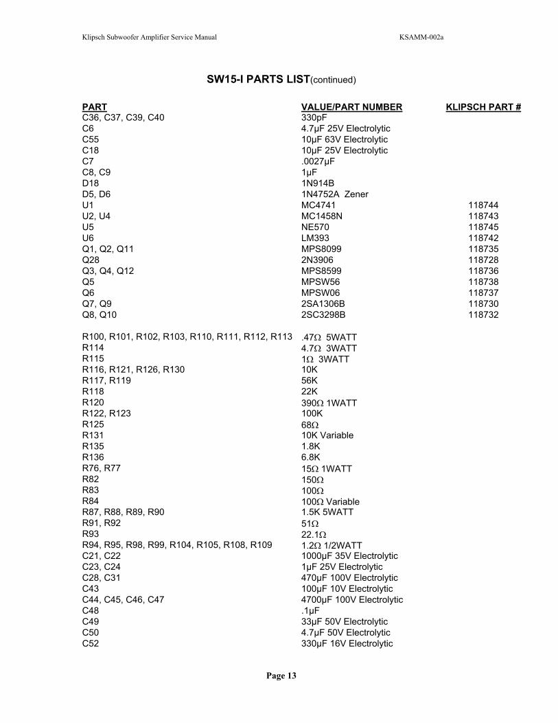
SW15-I PARTS LIST(continued)
PART VALUE/PART NUMBER KLIPSCH PART #C36, C37, C39, C40 330pFC6 4.7µF 25V ElectrolyticC55 10µF 63V ElectrolyticC18 10µF 25V ElectrolyticC7 .0027µFC8, C9 1µFD18 1N914BD5, D6 1N4752A ZenerU1 MC4741 118744U2, U4 MC1458N 118743U5 NE570 118745U6 LM393 118742Q1, Q2, Q11 MPS8099 118735Q28 2N3906 118728Q3, Q4, Q12 MPS8599 118736Q5 MPSW56 118738Q6 MPSW06 118737Q7, Q9 2SA1306B 118730Q8, Q10 2SC3298B 118732
R100, R101, R102, R103, R110, R111, R112, R113 .47 5WATTR114 4.7 3WATTR115 1 3WATTR116, R121, R126, R130 10KR117, R119 56KR118 22KR120 390 1WATTR122, R123 100KR125 68R131 10K VariableR135 1.8KR136 6.8KR76, R77 15 1WATTR82 150R83 100R84 100 VariableR87, R88, R89, R90 1.5K 5WATTR91, R92 51R93 22.1R94, R95, R98, R99, R104, R105, R108, R109 1.2 1/2WATTC21, C22 1000µF 35V ElectrolyticC23, C24 1µF 25V ElectrolyticC28, C31 470µF 100V ElectrolyticC43 100µF 10V ElectrolyticC44, C45, C46, C47 4700µF 100V ElectrolyticC48 .1µFC49 33µF 50V ElectrolyticC50 4.7µF 50V ElectrolyticC52 330µF 16V Electrolytic
Page 13
Klipsch Subwoofer Amplifier Service Manual KSAMM-002a
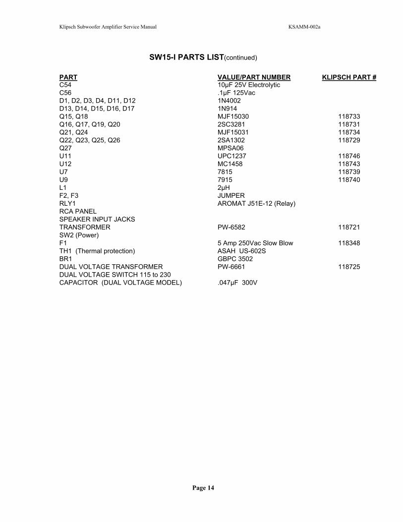
SW15-I PARTS LIST(continued)
PART VALUE/PART NUMBER KLIPSCH PART #C54 10µF 25V ElectrolyticC56 .1µF 125VacD1, D2, D3, D4, D11, D12 1N4002D13, D14, D15, D16, D17 1N914Q15, Q18 MJF15030 118733Q16, Q17, Q19, Q20 2SC3281 118731Q21, Q24 MJF15031 118734Q22, Q23, Q25, Q26 2SA1302 118729Q27 MPSA06U11 UPC1237 118746U12 MC1458 118743U7 7815 118739U9 7915 118740L1 2µHF2, F3 JUMPERRLY1 AROMAT J51E-12 (Relay)RCA PANEL SPEAKER INPUT JACKSTRANSFORMER PW-6582 118721SW2 (Power) F1 5 Amp 250Vac Slow Blow 118348TH1 (Thermal protection) ASAH US-602SBR1 GBPC 3502DUAL VOLTAGE TRANSFORMER PW-6661 118725DUAL VOLTAGE SWITCH 115 to 230CAPACITOR (DUAL VOLTAGE MODEL) .047µF 300V
Page 14