Service Manual Gas Wallhung Boiler - Central InstalOnly for authorized service technician ! Service...
35
Only for authorized service technician ! Service Manual Gas Wallhung Boiler Logamax plus 6 720 641 705-00.1O GB012 - 25K 2011/10 EN - U. Demir
Transcript of Service Manual Gas Wallhung Boiler - Central InstalOnly for authorized service technician ! Service...

Only for authorized service technician !
Service Manual Gas Wallhung Boiler
Logamax plus
6 72
0 64
1 70
5-00
.1O
GB012 - 25K
2011
/10
EN
- U
. Dem
ir

Content
GB012 - 25K2
Content
1 Safety precautions and symbols . . . . . . . . . . . . . . . 31.1 Symbols . . . . . . . . . . . . . . . . . . . . . . . . . . . . . 31.2 Safety precautions . . . . . . . . . . . . . . . . . . . . . 3
2 Service Functions . . . . . . . . . . . . . . . . . . . . . . . . . . . 42.1 Display Symbols . . . . . . . . . . . . . . . . . . . . . . . 42.2 Service Function . . . . . . . . . . . . . . . . . . . . . . 42.3 Service Function Overview . . . . . . . . . . . . . . 52.3.1 1. Service Level . . . . . . . . . . . . . . . . . . . . . . . 52.3.2 2. Service Level . . . . . . . . . . . . . . . . . . . . . . . 6
3 Failures / Errors . . . . . . . . . . . . . . . . . . . . . . . . . . . . . 73.1 Elimination of errrors . . . . . . . . . . . . . . . . . . . 73.2 Failure / Error Codes Overview . . . . . . . . . . . 83.3 Failure codes and corrections steps . . . . . . . 93.4 Sensor (NTC) Values . . . . . . . . . . . . . . . . . . 253.4.1 Flow Temperature Sensor . . . . . . . . . . . . . . 253.4.2 Domestic Hot Water Temperature Sensor . . 253.4.3 Flue Gas Safety Temperature Sensor (Behind
Burner) . . . . . . . . . . . . . . . . . . . . . . . . . . . . 253.5 Electrical Datas . . . . . . . . . . . . . . . . . . . . . . 263.6 Electrical Circuit Diagram . . . . . . . . . . . . . . . 273.7 Structure . . . . . . . . . . . . . . . . . . . . . . . . . . . . 293.8 Function Diagram . . . . . . . . . . . . . . . . . . . . . 31
4 Gas Values (Cental heating and domestic hot water circuit) 32

1 Safety precautions and symbols
GB012 - 25K 3
1 Safety precautions and symbols
1.1 Symbols
Signal words indicate the seriousness of the hazard in terms of the consequences of not following the safety instructions.
• Caution indicates that minor damage to property could result.
• Warning indicates that minor personal injury or serious damage to property could result.
• Danger indicates that serious personal injury could result. In particularly serious cases, lives could be at risk.
Notes contain important information in cases where there is no risk of personal injury or damage to property.
1.2 Safety precautions
If you smell gas
B Turn off gas service cook.
B Open windows.
B Do not operate any electrical switches.
B Extinguish any naked flames.
B Leave the building and telephone the gas company and authorized dealer from an outside phone.
If you smell fumes from the appliance
B Switch off the appliance.
B Open windows and doors.
B Inform your heating engineer.
Fitting and Modifications
B Fitting of the appliance or many modifications to be appli-ance may only be carried out by a compotent perEND.
B Flue systens must not be modified in any way.
B If the appliance has a type B.. flue system : Ventilation openings in doors, windows and walls must not be sealed or restricted. If draught-proof windows are installed, meas-ures must be taken to ensure there is an adequate supply of air to the appliance for combustion.
Inspection / Maintenance
B We recommend take out a to have the system regulary serviced in order to ensure that it functions reliably and safely.
B Only use original spare parts.
Combustible materials
B Do not store or use any combustible materials (paper, thin-ners, paints etc.) in the vicinty of the appliance.
Combustion Air / Ambient Air
B Keep combustion air/ambient air free of corrosive sub-stances (e. g. halogenated hydrocarbons which contain chlorine or fluorine compounds). In this way corrosion can be prevented.
Instructions to the customer
B Explain to the customer how the appliance works and how to operate it.
B Advise the customer that he / she must not make any mod-ifications to the appliance or carry out any repairs on it.
Safety instructions in this document are identi-fied by a warning-triangle symbol and are print-ed on a grey background.
Notes are identified by the symbol shown on the left. They are bordered by horizontal lines above and below the text.

2 Service Functions
GB012 - 25K4
2 Service Functions
2.1 Display Symbols 2.2 Service FunctionService functions are in divided in 2 level :• 1. Level (see page 5)• 2. Level (see page 6)
Fig. 1
1 Stand by (On/off) Button2 „Up (+)“ Button3 „Down (-)“ Button 4 Temparature Display (°C)5 Mode Button
Symbol Description
Save a parameter in service mode
Air bleeding function is active (service function : 1.2.C)
MAP (fan speed) (service func-tion : 2.b.d).
Siphon filling mode is active.
Domestic hot water circuit is active.
Key lock is active.
Summer mode.
Tab. 1
mode
1
0
23
4bar
45
2
36 720 643 530-26.1O
1

2 Service Functions
GB012 - 25K 5
2.3 Service Function Overview
2.3.1 1. Service Level
Operation
Change or query of a service function :
B Press mode, “+” and “-” button for 5 second. The service function will be shown on Display (e.g. 1.2.C).
B Select the desired/requested service code with “+” or “-” button.
B Press mode button again (for entering).After that you will see the selected (default) value on Display.
Changing / Adjustment of Value:
B Change the values with “+” or “-” button.
Storage/Save of Value :
B Press mode button until [ ] symbol will be shown on Display.
Exit from Service Level :
B For the exit from service level press the mode, “+” and “-” button for 5 second or Stand by button.The flow temperature will be shown again on display.
1. Level
Service Code Description Range
Initial (Factory
setting)
1.2.C Automatical Air Purging (0 = offý, 1= active ) Total time : 2 min. and 20 sec on/off intervall
0 - 1 0
1.2.F Operating Mode : (0 = Normal, 3= min. output, 4 = max. output) 0, 3 , 4 0
1.3.b Burner Anticycling 1 - 10 min. 3 min.
1.3.C Burner start hysterisis (for flow temp. NTC) 0 - 10 K 5 K
1.5.b Fan overrun 1 - 18 (x10) sec. 3 (=30 sec.)
1.6.A Last failure on memory 00 - FF -
1.6.d Display actual water flow rate by turbine ( l/min. ) 0 - 99
1.7.A LCD Backligth (1 = on, 0 = off) 0 - 1 1
Tab. 2 1. level service functions

2 Service Functions
GB012 - 25K6
2.3.2 2. Service Level
Operating
Change or query of a service function :
B To enter to 2. service level must be entered first in 1. level. Press mode, “+” and “-” button for 5 second. The service function onf1. level will be shown on Display (e.g. 1.2.C).
B To enter to 2. level : Press both “+” and “-” buttons for 3 second. The service function of 2. level will be shown on Display (e.g. 2.1.A).
B Select the desired/requested service code with “+” or “-” button.
B Press mode button again (for entering).After that you will see the selected (default) value on Display.
Changing / Adjustment of Value:
B Change the values with “+” or “-” button.
Storage/Save of Value :
B Press mode button until [ ] symbol will be shown on Display.
Exit from Service level :
B For the exit from service level press the mode, “+” and “-” button for 5 second or Stand by button.The flow temperature will be shown again on display.
2. Level
Service
Code Description Range Initial (Factory Setting)
2.1.A CH max. heat output 30 - 100 % 100 %
2.1.b DHW max. heat output (in winter mode) 30 - 100 % 100 %
2.2.b CH max flow temperature 35 - 82 °C 82 °C
2.3.d CH min. heat output 30 - 100 % 30 %
2.8.A Software version number e.g.. 162 112 -
2.8.E Reset to factory (default) setting 0 0
2.9.A Operation mode permanent : (0 = Normal, 1= min. power, 2 = max. power)
0 - 2 0
2.9.E Delay time for the turbine ( each unit = 0,5 sec.) 1 - 6 2
2.9.F Pump over run) (CH circuit) 0 - 10 min. 3
2.A.A Actual flow temperature ºC -
2.A.b Actual DHW temperatur ºC -
2.A.F Actual combustion chamber temperature ºC -
2.b.d Selection of flue length (MAP Value) (0 = off, 1 - 10 : fan speed accord-ing flue pipe length, see flue manuel for details)
0 - 10 0
2.b.F Solar mode delay time (sec.) 1 - 50 1
2.c.F Pump "over run” (DHW mode) ???? 0 - 30 sec. 5 sec.
2.0.A Gas Convertion (0 = NG, 1 = LPG) 0 -1 0
Tab. 3 2. level service functions

3 Failures / Errors
GB012 - 25K 7
3 Failures / Errors
3.1 Elimination of errrors
All regulation, control and safety equipment of appliance is controlled by the control unit.
If any failure during operation occurs, symbol and maybe will start to flash also. In additional the failure code will be shown on display (e.g. EA).
If and symbol on display flash:
B For the reset : Press mode and ”-” button until and symbol expire on display.The appliance will start up again and the flow temperature will be displayed.
If only symbol flashes:
B Switch the appliance first off and then on again by means of the standby key.The appliance will start up again and the flow temperature will be displayed.
If a failure can not be eliminated :B Contact your approved installer or Customer Service
for assistance, providing details of the fault and the appliance.
DANGER: Explosion !B Turn off gas cock before working on
gasbearing components.B Check for leaks before working on
gasbearing components.
DANGER: Poisoning !B Check for leaks before working on
gasbearing components.
DANGER: Risk of electric shock !B Always disconnect the power supply to
the appliance at the mains before carrying out any work on the electrical systems and components (fuse, circuit breaker).
NOTICE: Leaking water may damage the Cotronic module.B Cover the Cotronic module before
working on any parts that carry water.
For an overview of faults, see page 7.

3 Failures / Errors
GB012 - 25K8
3.2 Failure / Error Codes Overview
Failure Code on Display Failure Descripton Steps
MAP not selected (Fan speed adjustment according the flue pipe length).
Check the adjustment /selection via service func-tion 2.b.d).
1H Combustion chamber NTC failure (behind burner) : - when the temperature by CC NTC reached to limit or - when NTC not detected or open circuit
Check the and the heat exchanger surface, whether is blocked or not. And check the sensor and the connections.
2P Gradient limit : Temperature rises too rapidly in heating mode.
Check the pump, system pressure and by-pass circuit.
3A Fan sensor not detected. Check the fan.
3C Fan speed can not reached to target speed. Check the fan for the blockage and the electrical supply.
4C Overheat lock-out by temperatur limiters (STBs) (Flue gas + prim. Heatexchanger). In this case ; Heat demands is blocked and pump stops 3 min. later.
Check the system presseure, temperature sensor, pump and fuses on board. Discharge the air in system. Check also the flue gas pipe and heatex-changer.
4Y Flow temperature sensor failure (pump is run-ning).
Check the flow temperature sensor and the con-nection.
6A Ignition lock-out (flame not detected) (pump is running).
Check the gas cock, gas pressure, electrode and the cable connection.
6C Safety valve leaks. Check the gas valve, the cable connection and electrode set.
B3 Short circuit / failure in water level switch. Check the condensate water drain and recuperator (condens-heatexchanger).
CL Domestic hot water temperature sensor not correct installed or failure.
Check the sensor and cable connection.
d7 Modulator coil failure (regulator valve on gas valve)
Check the cable connection.
Tab. 4 Failure codes

3 Failures / Errors
GB012 - 25K 9
3.3 Failure codes and corrections steps
4C is flashing.
Overheat lock-out by temperatur limiters (2 x STB : Flue gas + prim. Heatexchanger). In this case ; Heat demands is blocked and pump stops 3 minutes later.
Control Step Action
1. Is the system pressure between 1 - 2 bar?
yes: -->2.
no: B Fill water in sysytem.B Bleed the system 1).B Press RESET button and restart again.
4C failure still exist? -->2.
2. Is the circulation pump blocked ? yes: B Eliminate the blockage (turn the shaft).If not succesful :
B Switch off the appliance.B Cut mains supply.B Drain the water from appliance.B Change the pump.B Fill with water and bleed the system again.B Connect to main supply.B Switch on the appliance.B Press RESET button and restart again.
4C failure still exist? -->3.
no: -->3.
3. Check the flue gas pipe line.
Is there any blockage ?
yes: B Check the flue gas pipe and remove the block-age.
B Switch on the appliance.B Cihazý resetleyip yeniden çalýþtýrýn.
4C failure still exist? -->4.
no: -->4.
4. Check the recuperator.
Is there any blockage?
yes: B Clean the recuperator. Replace if necessary.B Switch on the appliance.B Press RESET button and restart again.
4C failure still exist? -->5.
no: -->5.
5. B Switch off the appliance.B Check the temperature limiter
(STB) on recuperator. Ist the circuit open or wrong installed ?
no: -->6.
yes: B Change the temperature limiter (STB) or correct the installation.
B Switch on the appliance.
-->6.

3 Failures / Errors
GB012 - 25K10
6. Electronic card is defect. B Switch off the appliance.B Cut mains supply.B Change the electronic card.B Connect to main supply.B Switch on the appliance.B END
1) If the air inside not removed/discharged, can be also used the manuel air vent valve in recuparator.
4C is flashing.
Overheat lock-out by temperatur limiters (2 x STB : Flue gas + prim. Heatexchanger). In this case ; Heat demands is blocked and pump stops 3 minutes later.
Control Step Action

3 Failures / Errors
GB012 - 25K 11
6A is flashing.
Ignition lock-out (flame not detected) (pump is running)
Control Step Action
1. Dose the burner flame can be seen? yes: -->6.
no: -->2.
2. Gas inlet cock open? yes: -->3.
no: B Open the gas inlet cock.B Press RESET button and restart again.
6A failure still exist? -->3.
3. Air in the gas pipe line? yes: B Open the gas inlet cock.B Press RESET button and restart again.
6A failure still exist? -->4.
no: -->4.
4. Ist the thermal gas inlet cock acti-vated ?
(if it is installed)
yes: B Change the cock.B Press RESET button and restart again.
6A failure still exist? -->5.
no: -->5.
5. Natural gas :Is there any gas pressure regulator at the house entrance ?
yes: B Check if the montage of the gas pressure regu-lator assembly is correct or not ? If necessory correct it.
B M6Asure the gas inlet pressure. If there is a deviation inform the gas distributor company.
B Press RESET button and restart again.
6A failure still exist? -->6.
no: -->6.
LPG (liquid gas):Is there sufficient gas flow in the LPG line to operate appliance ?
yes: -->6.
no: B Is the tank full enough ?B Is there any air in the gas pipe?B Is the external tank magnet valve tripgered ?B Is the gas entry pressure OK? ( if too high check
the regulator).B Press RESET button and restart again.
6A failure still exist?-->6.
6. Is the groun d i n g connection done correctly?
yes: -->7.
no: B Correct ground connection.B Press RESET button and restart again.
6A failure still exist ? -->7.

3 Failures / Errors
GB012 - 25K12
7. Is the gas valve working ?B Switch off the appliance.B Pull out the gas valve cables.B Measure resistances from safety
valves.
yes: B Connect the cables.B Switch on the appliance.B Press RESET button and restart again.
6A failure still exist ? -->8.
no: B Cut mains supply.B Close the gas inlet cock.B Change the gas valve.B Open the gas inlet cock.B Connect to main supply.B Connect the cables.B Switch on the appliance.B Make sure there is no gas l6Akage l6Aking.B Press RESET button and restart again.
6A failure still exist ? -->8.
8. Is the ignition correct ? yes: -->12.
no: -->9.
9. Check connection of ignition cable and electrode is correct or not?
yes: -->10.
no: B Connect the cable.B Press RESET button and restart again.
6A failure still exist ? -->10.
10. Is the ignition cable assembled cor-rectly?
yes: -->11.
no: B Switch off the appliance.B Correct the ignition cable connection.B Switch on the appliance.B Press RESET button and restart again.
6A failure still exist ? -->11.
11. Check ignition electrode for damage and oxidation ?
yes: B Switch off the appliance.B Change the ignition cable.B Switch on the appliance.B Press RESET button and restart again.
6A failure still exist ? -->12.
no: -->12.
12. B Is ionisation current OK ? yes: -->13.
no: B Change the ionisation electrode and check the assembly of ignition brigde.
B Press RESET button and restart again.
6A failure still exist ? -->13.
6A is flashing.
Ignition lock-out (flame not detected) (pump is running)
Control Step Action
3 Failures / Errors
GB012 - 25K 13
13. Cable harness is damaged. B Switch off the appliance.B Cut mains supply.B Change the cable harness. B Connect to main supply.B Switch on the appliance.B Press RESET button and restart again.
6A failure still exist ? -->14.
14. Electronic card is defect. B Switch off the appliance.B Cut mains supply.B Change the electronic card.B Connect to main supply.B Switch on the appliance. END.
6A is flashing.
Ignition lock-out (flame not detected) (pump is running)
Control Step Action

3 Failures / Errors
GB012 - 25K14
4Y is flashing.
Central heating flow temperature sensor failure (pump is running).
Control Step Action
1. Check if CH flow temperature sensor (NTC) is damaged or not ?B Switch off the appliance.B Pull cables out.B Measure the electrical resistance
of the NTC sensor.Are the measured values OK ? (resistance table)
yes: B Check the connection terminal on NTC.
4Y failure still exist ? -->2.
no: B Change NTC.B Connect the cable.B Switch on the appliance.
4Y failure still exist ? -->2.
2. Check if the cables are damaged or not?.B Switch off the appliance.B ·If NTC changed :
- disassemble the NTC cable from NTC.- measure the sensor resistance.- assemble the NTC to NTC cable again.
B Pull out the 20 poled (main socket) connector from the electronic card.
B Measure the electrical resistance of NTC on socket. Are the meas-ured resistance values at at NTC and socket connection same?
yes: B Chance the cable harness.B Switch on the appliance.
4Y failure still exist ? -->3.
no: -->3.
3. Electronic card is defect. B Switch off the appliance.B Cut mains supply.B Change the electronic card.B Connect to main supply.B Switch on the appliance.

3 Failures / Errors
GB012 - 25K 15
1H is flashing.
Cumbustion chamber temperature sensor 1) is defect, not detected or overheating in cumbustion cham-ber (pump runs continuously)
Control Step Action
1. Check if combustion chamber NTC damaged or not and the position.B Switch off the appliance.B Pull the NTC cables out.B Measure NTC resistance.
Are the values correct ? (see NTC values)
yes: B Check the cable connection.
1H failure still exist ? -->2.
no: B Change the NTC.B Connect the cable.B Switch on the appliance.
1H failure still exist ? -->2.
2. Check if cable damaged or not.B Switch off the appliance.B In case of NTC is cahnged :
- Pull the NTC cables out.- Measure NTC resistance.- Reconnect the NTC cable.
B Pull out the 20 poled connector on control unit.
B Measure the NTC resistance directly on 20 poled connector. Are the measured values on NTC and cocnector different ?
yes: B Change the cable harness.B Switch on the appliance.
1H failure still exist ? -->3.
no: -->3.
3. Is there any blockage on flue gas pipe?
yes: B Remove the blockage.
1H failure still exist ? -->4.
no: -->4.
4. Is the correct MAP (fan speed) value according flue gas pipe length choosen ?
no: B Adjust correct MAP value according flue gas pipe length and diameter. See capitel 7.2.
1H failure still exist ? -->5.
yes: -->5.
5. Is fan running correct ? no: B Change the fan.
1H failure still exist ? -->6.
yes: -->6.

3 Failures / Errors
GB012 - 25K16
6. Check the burner gas pressure. Are the values OK ?
yes: B Correct the gas pressure values. If not possible, change the gas valve.
1H failure still exist ? -->7.
no: -->7.
7. Is the heat exchanger and recupera-tor surface dirty or damaged (block-age) ?
yes: B Remove the blockage.
1H failure still exist ? -->8.
no: -->8.
8. Electronic card is defect. B Switch off the appliance.B Cut mains supply.B Change the electronic card.B Connect to main supply.B Switch on the appliance.
1) The sensor is activated after 1 minute. After 3. failure the boiler is blocked. By first 2. time it will be reseted automaticly after 15 min.
1H is flashing.
Cumbustion chamber temperature sensor 1) is defect, not detected or overheating in cumbustion cham-ber (pump runs continuously)
Control Step Action

3 Failures / Errors
GB012 - 25K 17
CL is flashing.
DHW (Domestic Hot Water) NTC not installed correctly or defect. The appliance doesn’ t run in summer mode. It works in winter mode and shows the failure code with alternately.
Control Step Action
1. Check the DHW NTC whether it is cor-rect installed or not.
CL failure still exist ? -->2.
2. Check if water NTC damaged or not ?.B Switch off the appliance.B Pull out NTC cables.B Measure resistance of NTC (Ohm).
Is the NTC resistance value OK ?
yes: B Change the cable harnness.B Switch on the appliance.
CL failure still exist ? -->3.
no: -->4.
3. Check if cable damaged or not.B In case of NTC is cahnged :
- Pull the NTC cables out.- Measure NTC resistance.- Reconnect the NTC cable.
B Switch off the appliance.B Pull out the 20 poled connector on
control unit.B Measure the NTC resistance
directly on 20 poled connector. Are the measured values on NTC and cocnector different ?
yes: B Change the cable harnness.B Switch on the appliance.
CL failure still exist ? -->4.
no: -->4.
4. Check the DHW circuit in main heat exchanger whether it is calcified or not.
B In case of calcification, clean it with special pump. If necessary change the heat exchanger.
CL failure still exist ? -->5.
5. Electronic card is defect. B Switch off the appliance.B Cut mains supply.B Change the electronic card.B Connect to main supply.B Switch on the appliance.

3 Failures / Errors
GB012 - 25K18
2P is flashing.
A fast temperature increase detected in central heating (CH) (> 2,7 K/sec). The appliances will be resetet automaticly, if the flow temp. < 40 ºC.
Control Step Action
1. B Check system pressure on manome-ter.
Is the system pressure > 0,5 bar ?
yes: -->2.
no: B Fill the system with water.
2P failure still exist ? -->2.
2. B Is there air in the system ?. yes: -->3.
no: B Remove the air in system.
2P failure still exist ? -->3.
3. B Check if water is circulated ? yes: -->4.
no: B Check and clean pump, filters and return and flow valves.
2P failure still exist ? -->4.
4. Electronic card is defect. B Switch off the appliance.B Cut mains supply.B Change the electronic card.B Connect to main supply.B Switch on the appliance.

3 Failures / Errors
GB012 - 25K 19
3A is flashing.
Fan sensor not detected. (This failure only occurs if there is a sensor or the cable physical defect)
Control Step Action
1. Is th fan cables damaged ? yes: B Switch off the appliance.B Change the cables.B Switch on the appliance.
3A failure still exist ? -->2.
no: -->2.
2. Is there any problem at fan sensor and cable ?B Switch off the appliance.B Check the sensor and cable.
yes: B Change the cable and sensor.B Switch on the appliance.
3A failure still exist ? -->3.
no: -->3.
3. Electronic card is defect. B Switch off the appliance.B Cut mains supply.B Change the electronic card.B Connect to main supply.B Switch on the appliance.

3 Failures / Errors
GB012 - 25K20
3C is flashing.
Target fan speed can not reached or blockage problem.
Control Step Action
1. Is the flue gas pipe blocked ? no: -->2.
yes: B Switch off the appliance.B Clean the flue gas pipe.B Switch on the appliance.
3C failure still exist? -->2.
2. Check the power voltage supply.
Is voltage below 160 V AC ?
yes: B Switch off the appliance.B Inform related persons/company.B Switch on the appliance.
3C failure still exist? -->3.
no: -->3.
3. Check the fan it self. Is there any blockage or others problems?
no: -->4.
yes : B Switch off the appliance.B Change the fan.B Switch on the appliance.
3C failure still exist? -->4.
4. Electronic card is defect. B Switch off the appliance.B Cut mains supply.B Change the electronic card.B Connect to main supply.B Switch on the appliance.

3 Failures / Errors
GB012 - 25K 21
6C is flashing.
After switching off gas flame detected (even the safety valves are closed (leakege))
Control Step Action
1. Gas valve is defect. B Switch off the appliance.B Change the gas valve.B Switch on the appliance.B Check the leakage.B Press RESET button and restart again.
6C failure still exist? -->2.
2. Electronic card is defect. B Switch off the appliance.B Cut mains supply.B Change the electronic card.B Connect to main supply.B Switch on the appliance.

3 Failures / Errors
GB012 - 25K22
B3 is flashing.
Short circuit / failure in water level switch in recuperator (condens heat exchanger).
Control Step Action
1. Check the siphon line.
Is there any blockage ?
yes: B Remove the blockage.B Switch on the appliance.
B3 failure still exist? -->2
no: -->2.
2. Check the water level switch.
Is the resistance lower 300 kOhm ?
yes: B Accumulated water in recuperaotr or switch contacts are wet.
B It can be blockage at recuperator drain. Correct it.
B Is the siphon connection adapter in right posi-tion. It should be in vertical position.
B Leakage in water level switch ?. If yes, change it.
B3 failure still exist? -->3.
no: B Short circuit in connection cable. If necessary, change it.
B3 failure still exist? -->3.
3. Electronic card is defect. B Notice the changed parameters.B Switch off the appliance.B Cut mains supply.B Change the electronic card.B Connect to main supply.B Switch on the appliance.B Adjust again according noticed parameters.

3 Failures / Errors
GB012 - 25K 23
d7 is flashing.
Appliance doesn’t modulate / Regulator valve problem (don’t regulate to max. position).
Control Step Action
1. Check if the regulator valve cable damaged or not and the connection. Are the connections wrong?
yes: B Change the cable harness or correct it.B Switch on the appliance.
d7 failure still exist ? -->2.
no: -->2.
2. Check the resistance from regulator valve.B Switch off the appliance.B Pull out the 20 poled connector on
control unit.B Measure the resistance.
Is deviation of resistance values ?
yes: B Change the cable harness.B Switch on the appliance.
d7 failure still exist ? -->3.
no: -->3.
3. Check the resistance from regulator valve.B Reglaj ventiline gerilim/akým geliyor
mu ?B Measure the resistance directly on
gas valve.
Is there deviation of resistance val-ues between two messurements ?
yes: B Change the gas valve.B Switch on the appliance.
d7 failure still exist ? -->4.
no: -->4.
4. Electronic card is defect. B Switch off the appliance.B Cut mains supply.B Change the electronic card.B Connect to main supply.B Switch on the appliance.

3 Failures / Errors
GB012 - 25K24
I I is flashing.
MAP not selected (Fan speed adjustment according the flue pipe length)
Attention : The appliance is delivered with MAP value “0” (service function : 2.b.d). In this condition the appliance doesn’t run. The “I I” symbol will be shown on display alternately.
Control Step Action
1. MAP value is according the flue gas pipe length not selected.
yes: B Adjust the MAP value via service fonction 2.b.d. (for details, see flue gas instruction manuel)
I I symbol still exist ? -->2.
no: -->2.
2. Electronic card is defect. B Switch off the appliance.B Cut mains supply.B Change the electronic card.B Connect to main supply.B Switch on the appliance.

3 Failures / Errors
GB012 - 25K 25
3.4 Sensor (NTC) Values
3.4.1 Flow Temperature Sensor
3.4.2 Domestic Hot Water Temperature Sensor
3.4.3 Flue Gas Safety Temperature Sensor (Behind Burner)Temperature ( °C)
Measure Tolerance ± %10 Resistance (Ohm)
20 14 77225 11 98130 9 78635 8 04740 6 65345 5 52350 4 60855 3 85660 3 24365 2 74470 2 33275 1 99080 1 70485 1 46490 1 26295 1 093100 950
Tab. 5
DHW Temperature Sen-sor ( °C ) Resistance (Ohm)
0 33 24210 19 94720 12 39430 7 94740 5 24250 3 54860 2 45970 1 74080 1 25690 923
Tab. 6
Temperature ( °C) Measure Tolerance
± %10 Resistance (Ohm)
0 27 93620 12 13640 5 77460 2 96780 1 629100 947120 578140 387160 244180 168200 119210 101220 86240 64260 49
Tab. 7

3 Failures / Errors
GB012 - 25K26
3.5 Electrical Datas
Description Supply Voltage Value Tolerance Remarks
Termperature Limiter
Pramiary HE
24 VDC 0 Ohm - Temp. Limit = 110 ºC
Termperature Limiter
(Recuperator-Flue gas)
24 VDC 0 Ohm - Temp. Limit = 100 ºC
DHW Temp. Sensor (NTC)
5 VDC 20 ºC => 12,4 kOhm 60 ºC => 2,5 kOhm
± 0,5 kOhm --
Flow Temp. Sensor (NTC)
5 VDC 20 ºC => 14,8 kOhm 60 ºC => 3,2 kOhm
± 0,5 kOhm see resistance table
Flue gas safety (Com-bustion chamber ) Sen-sor (NTC, behind burner)
5 VDC 20 ºC => 12,1 kOhm 60 ºC => 2,9 kOhm
± 0,5 kOhm ---
Pump 230 VAC I = 495 Ohm
II = 355 Ohm
III = 220 Ohm
± 10 Ohm ---
Ionisation Electrode -- ca. 3 - 5 µA -
Gas Safety Valve 1 230 VAC 1,55 kOhm ± 10 Ohm
Gas Safety Valve 2 230 VAC 8 kOhm ± 20 Ohm common (neutral) (black cable)
Gas Regulator 0 - 24 VDC ca. 80 Ohmmin. 25 mAmax. 130 (LPG 165)mA
± 5 Ohm
Fan 230 VAC 38 Ohm ± 5 Ohm
Fan Sensor 1. Vcc = 5VDC (supply)
2. GND (-)
3. Vout (Signal) 5 VDC
check physical - ---
2 ad. Fuse T 1,6 A, 230 VAC (L + N.)
230 VAC 0 Ohm - Cut supply !
Water level switch 24 VDC 300 kOhm (during operation)
In case of short circuit : < 300 kOhm.
Water Flow Rate Sen-sor (Turbine)
1 = “-” 0 VDC
2 = Signal 0-5 VDC
3 = “+” 5 VDC
9,6 Hz = 1,5 l/dk.
68,7 Hz = 10 l/dk.
± 2 Hz
± 6 Hz
Can measured in Hz between 1. and 2. cable.
Tab. 8

3 Failures / Errors
GB012 - 25K 27
3.6 Electrical Circuit Diagram
Fig. 2
6 720 643 530-07.2O
12
1
5
109
14 5
2
6
17
15 4
16
2
3
711
13
3
8
18

3 Failures / Errors
GB012 - 25K28
Legends :
1 Fan2 Flue gas temperature limiter (STB) (Recuperator)3 Water level switch4 Ionisation electrode5 Pump6 Turbine7 LCD Dispaly connection8 Transformer9 Controller (room thermostat) connection10 Diagnostic connection11 Igniton transformer12 Supply cable13 DHW temperature sensor (NTC)14 Gas valve15 Ignition electrode16 Temperatur limiter (STB) 17 Flow temperature sensor18 Flue gas safety (combustion chamber) sensor
3 Failures / Errors
GB012 - 25K 29
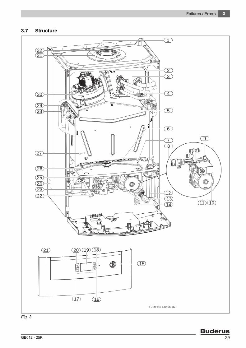
3.7 Structure
Fig. 3
mode
reset
20
6 720 643 530-06.1O
18
17 16
15
22
25
26
23
29
30
3231
23
5
7
1
8
9
1011
1213
21 19
4
28
14
6
24
27

3 Failures / Errors
GB012 - 25K30
Key to Figures :
1 Expansion vessel2 Flue gas temperature limiter (STB)3 Condesing-Heat Exchanger (Recuperator)4 Water level switch (Condensate backup sensor)5 Combustion chamber6 Distribution pipe (Inj. nozzle)7 Ionisation electrode8 Safety valve (heating circuit)9 Autom. air vent valve10 Circulation pump11 Pump speed switch12 Condensate siphon13 Turbine14 Condensate water hose15 Manometer16 (-) Button17 Mode Button18 (+) Button19 Display 20 Stand-by (On/off) Button21 Control unit22 Water filling valve23 Gas Valve 24 Type lable25 DHW temperature sensor26 Ignition electrode27 Flue gas safety sensor (Combustion chamber sensor)
(behind burner)28 Flow temperature sensor29 Temperature limiter for heating block30 Fan31 Combustion air inlet32 Flue gas pipe

3 Failures / Errors
GB012 - 25K 31
3.8 Function Diagram
Fig. 4
1 Control Unit (Cotronic 3)2 Water filling valve 3 By-pass pipe4 DHW temperatur sensor5 Flow temperature sensor6 Temperatur limiter7 Combustion chamber (flue gas safety) sensor8 Ionisation electrode9 Inj. nozzle10 Burner11 Ignition electrode12 Heatexchanger13 Combustion chamber (fresh air)14 Combustion chamber15 Fan16 Condensate-Heatexchanger (Recuperator) 17 Flue gas pipe18 Expansion vessel19 Autom. air vent valve20 Circulation pump
21 CH safety valve22 Siphon23 Turbine24 DHW water flow rate limiter + Filter25 Manometer26 Gas valve27 Siphon (trichtersiphon) (ops.)28 Regulator valve 29 Gas filter30 Measurement point (Inj. pressure)31 Measurement point (Gas inlet pressure)32 Safety valve33 CH-Return circuit34 DHW inlet35 Gas inlet36 DHW outlet37 CH- Flow38 Manuel air vent valve40 Flue gas temperature limiter (STB)

4 Gas Values (Cental heating and domestic hot water circuit)
GB012 - 25K32
4 Gas Values (Cental heating and domestic hot water circuit)
Burner pressure Gas flow rate
(mbar) (l/min.) (kg/h)
Gas Type G20 G30 G20 G30
Wobbe indeks 15 °C, 1013 mbar (kWh/ m³) 14,1 24,3
Net calorific value 15 °C, Hs (kWh/ m³) 10,5 34,9
Display Güç (kW )
30 7,8 1,3 2,3 13,8 0,6
50 9,9 2,1 3,7 17,5 0,8
53 10,5 2,4 4,2 18,6 0,8
56 11,4 2,8 4,9 20,2 0,9
60 13,1 3,6 6,4 23,2 1,0
63 14,6 4,5 7,9 25,9 1,1
66 16,0 5,4 9,5 28,4 1,3
70 17,5 6,5 11,3 31,1 1,4
73 18,8 7,4 13,0 33,4 1,5
77 20,3 8,7 15,0 36,1 1,6
80 22,0 10,1 17,6 39,2 1,7
84 23,5 11,5 19,9 41,9 1,9
87 25,0 13,0 22,5 44,6 2,0
90-100 25,5 13,5 23,2 45,5 2,0
Tab. 9

4
GB012 - 25K 33
Notes

4
GB012 - 25K34