Service Manual for Cuber Model CS0415 - SCOTSMAN; ICE
26
Service Manual for Cuber Model CS0415
Transcript of Service Manual for Cuber Model CS0415 - SCOTSMAN; ICE

Service Manual for
Cuber Model CS0415
Table of Contents
Specifications . . . . . . . . . . . . . . . . . . . . . . . . . . . . . . . . . . . . . . . . . . Page 3
Installation: . . . . . . . . . . . . . . . . . . . . . . . . . . . . . . . . . . . . . . . . . . . Page 4
Test Mode - Ice Thickness Adjustment . . . . . . . . . . . . . . . . . . . . . . . . . . . . . Page 5
Technical Charts: . . . . . . . . . . . . . . . . . . . . . . . . . . . . . . . . . . . . . . . . Page 6
Operational Modes: . . . . . . . . . . . . . . . . . . . . . . . . . . . . . . . . . . . . . . . Page 7
Harvest Mode . . . . . . . . . . . . . . . . . . . . . . . . . . . . . . . . . . . . . . . . . . Page 8
Component Location . . . . . . . . . . . . . . . . . . . . . . . . . . . . . . . . . . . . . . Page 9
Component Location . . . . . . . . . . . . . . . . . . . . . . . . . . . . . . . . . . . . . . Page 10
Diagnostic Mode . . . . . . . . . . . . . . . . . . . . . . . . . . . . . . . . . . . . . . . . Page 11
Error Displays . . . . . . . . . . . . . . . . . . . . . . . . . . . . . . . . . . . . . . . . . . Page 12
Component Testing . . . . . . . . . . . . . . . . . . . . . . . . . . . . . . . . . . . . . . . Page 13
Component Testing . . . . . . . . . . . . . . . . . . . . . . . . . . . . . . . . . . . . . . . Page 14
Flow Chart - Overall Operation . . . . . . . . . . . . . . . . . . . . . . . . . . . . . . . . . Page 15
Flow Chart - Freeze Mode Details . . . . . . . . . . . . . . . . . . . . . . . . . . . . . . . Page 16
Service Diagnosis . . . . . . . . . . . . . . . . . . . . . . . . . . . . . . . . . . . . . . . . Page 17
Service Diagnosis . . . . . . . . . . . . . . . . . . . . . . . . . . . . . . . . . . . . . . . . Page 18
Removal and Replacement - Thermistor . . . . . . . . . . . . . . . . . . . . . . . . . . . . Page 19
Removal and Replacement . . . . . . . . . . . . . . . . . . . . . . . . . . . . . . . . . . . Page 20
Removal and Replacement - Controller . . . . . . . . . . . . . . . . . . . . . . . . . . . . . Page 21
Removal and Replacement . . . . . . . . . . . . . . . . . . . . . . . . . . . . . . . . . . . Page 22
Removal and Replacement - Evaporator . . . . . . . . . . . . . . . . . . . . . . . . . . . . Page 23
July 2007Page 2
CS0415Service Manual
Introduction
This is the service manual for the CS0415 icemachine.
Basic installation information is provided, howeverthe installation manual is separate.
Note and heed any warning symbols where theyappear.

Specifications
Scotsman Ice Systems are designed andmanufactured with the highest regard for safetyand performance. They meet or exceed thestandards of agencies like NSF and UL..
Scotsman assumes no liability or responsibility ofany kind for products manufactured by Scotsmanhat have been altered in any way, including the useof any part and/or other components notspecifically approved by Scotsman.
Scotsman reserves the right to make designchanges and/or improvements at any time.Specifications and design are subject to changewithout notice.
AC Power Supply:
• 104 to 127 VAC (rated 115 VAC), 60 Hz
Amperage:
• 6.5 Amps (max)
Minimum Circuit Capacity:
• 15 Amps
Ice Production per 24 hours (Approximate)
• 70oF (27
oC) 46 lbs (21 kg)
• 80oF (27
oC) 47 lbs (21 kg)
• 90oF (32
oC) 40 lbs (18 kg)
• 100oF (38
oC) 40 lbs (18 kg)
Ice Shape:
• 3/4" x 3/4" Square
Ice Thickness @ Normal Setting (Approximate)
• 0.32" or 5/16" (8.1 mm)
Ice Thickness @ Thin Setting (Approximate)
• 0.28" or 9/32" (7.0 mm)
Ice Thickness @ Thick Setting (Approximate)
• 0.39" or 3/8" (9.9 mm)
Storage Capacity (Approximate)
• 24 lbs. (10.9 kg)
Exterior Dimensions (W x D x H)
• 15" x 24" x 34" (381 or 457.2 x 609.6 x 863.6
mm)
Exterior Finish:
• Painted Steel
Net Weight:
• 94 lb. (42.6 kg)
Cube Thickness Control:
• Thermistor under Evaporator & ControlBoard Setting
Harvest Control:
• Thermistor under Evaporator & ControlBoard Setting
Bin Ice Level Control:
• Thermistor on side of Bin
Refrigerant:
• R-134a (6.2 oz). Weigh into high side only.
Ambient Temperature Operation Range:
• 55 to 100oF
Water Pressure Operating Range
• 20 to 120 psig
Water Consumption (Dependent On WaterPressure)
• 6 to 10 gallons per 4 hours
July 2007Page 3
CS0415Service Manual

Installation:
The ice machine is designed to be installedindoors, in a controlled environment. Do not placewhere the temperature limits for air or water areexceeded.
The water supply must be cold, potable water. Adrain must be nearby or a drain pump model usedor a gravity drain model must be converted to use adrain pump.
The ice machine must be on its own electricalpower circuit. The machine must be grounded. Donot connect to an extension cord. Do not cut off theground prong off the power cord plug. Do notbypass the ground prong.
The cabinet is designed to be either free standingor built in. In either case the area in front of thekickplate must be free of obstruction. Blocking thisarea will cause low ice capacity and likely damagethe machine. Such damage is considered mis-useand is not covered by warranty.
When building into a cabinet, be sure the powersupply, water and drain are all available within thebuilt in area.
July 2007Page 4
CS0415Service Manual
Water Inlet
Back View
Drain Hose*
Vent Hose*
* Drain Pump Models

Test Mode - Ice Thickness Adjustment
The CS0415 has three push button switches: ON,OFF and CLEAN. These can be used to switch themachine on, off and to start the cleaning process.They can also be used to test the unit'scomponents.
To test and/or to adjust ice thickness:
1. Unplug or disconnect the unit from the powersupply.
Note: Unit must be On (make ice mode) whenpower is disconnected.
2. Reconnect power to the unit.
3. Immediately, within ten seconds of powerre-connection, push and hold the On and Cleanbuttons until the three indicator lights begin to blink.
4. Push and release the On button to cycle throughtesting the various components.
Note: 10 push-and-releases will switch thecontroller to ice thickness adjustment mode.
Pre-Test Mode: All 3 lights are on steady.
Test 1, testing the bin thermistor. The On light isthe indicator, if it is on steady, it is OK. If it blinkstwice and repeats, it is open. If it blinks 4 times andrepeats, it is shorted.
Test 2, testing the evaporator thermistor. TheClean light is the indicator, if it is on steady, it isOK. If it blinks twice and repeats, it is open. If itblinks 4 times and repeats, it is shorted.
Test 3, testing the inlet water valve. Four minutetest.
Test 4, testing the water level sensor.
Test 5, testing the water pump.
Test 6, Testing the reservoir drain pump.
Test 7, testing the compressor and condenser fanmotor.
Test 8, testing the compressor and hot gas valve.
Test 9, no component tested.
Test 10, displaying the ice thickness setting.
Ice Thickness Adjustment.
The Off light is the indicator.
• If it blinks 2 times and repeats, the icethickness is set at thin.
• If it blinks 4 times and repeats, the icethickness is set at normal.
• If it blinks 6 times and repeats, the icethickness is set at thick.
Pushing and releasing the Clean button betweenflashes adjusts the thickness setting to the nextone.
July 2007Page 5
CS0415Service Manual

Technical Charts:
July 2007Page 6
CS0415Service Manual
Bin Thermistor
Cut-In Cut-Out
Temperature Resistance Temperature Resistance
Bin 40oF. +/- 1
oF. 25.9k ohms +/- 3 % 35
oF +/- 1
oF. 29.8 ohms +/- 3 %
Evaporator Thermistor
End Harvest Readings
Ice Thickness Temperature Resistance
Normal
52oF. +/- 3% 18.7k ohms +/-1%Thick
Thin
Other Technical Information
Wattage @ 120 V Resistance
Compressor 244
Run 1 - 5
Start 3 - 11
Water pump 7.5 3.6
Reservoir drain pump 4.5 3.6
Water valve 20
Hot gas valve 7 - 9 385
Bin thermistor 10k @ 77oF.
Evap thermistor 10k @ 77oF.
Transformer 73
Fan motor 5.1 - 7.1 185
Cutter grid 20

Operational Modes:
There are four main operational modes for the icemaker:
• Freeze
• Harvest
• Clean
• Service (Diagnostics)
Ice Making Cycle
In addition, there are three possible “Off” cycles forthe ice maker. They occur when:
1. The bin is full of ice and the LED is illuminated“ON/OFF” (Idle mode).
2. The “On/OFF” control switch has been held forthree seconds. The ON/OFF LED will go out.
Electrical System
Line Voltage is supplied to the electrical controlswitches and the primary side of the step-downdual transformer. The dual transformer reduces
120 VAC to 8.75 VAC for the cutter grid and the
bin light and 12 VAC for the drain and
recirculating pumps. The electronic control boarddirects 12 VAC to the water recirculating andreservoir drain pumps, and 120 VAC to the hot gassolenoid, condenser fan motor, and compressor.The measured fill water valve will always have 120VAC on the BK and WH wires and 14 VDC on theOR/WH and BK/RD wires.
An evaporator thermistor supplies temperatureinformation to the electronic control to determinewhen to terminate the harvest cycle.
Refrigeration System
The hot gas refrigerant, under high pressure, isforced through the condenser, where it changesinto a liquid, and flows through the drier andcapillary tube into the evaporator. Under lowpressure in the evaporator, the liquid refrigerantabsorbs heat from the water flowing over theevaporator as the refrigerant evaporates into a gas.As a low pressure gas, the refrigerant flows backthrough the suction line of the heat exchanger, tothe compressor.
During the Freeze mode, some of the hot gas thatis in the condenser accumulating tube, condensesto a liquid, and remains in the accumulating tube.
During the later stages of the Freeze mode, as theice slab forms on the evaporator freezing plate,some of the refrigerant passing through theevaporator will not evaporate into a gas, but willremain a liquid. This liquid refrigerant will settle inthe accumulator, while the refrigerant vapor issucked off through the suction tube at the top of theaccumulator. This accumulated liquid refrigerantwill eventually be directed to the evaporator toquickly warm the evaporator plate during theHarvest mode.
Note: It is very important that the accumulator isnot tilted out of a horizontal position. If moved, itcould cause compressor failure.
Water System
The water recirculating pump moves the water fromthe reservoir pan up to the distributor, where itflows out over the evaporator freezing plate.
Water that does not freeze on the evaporator plateruns off the front edge, and falls back into thereservoir, where it is recirculated back to the waterdistributor.
As the ice slab forms, the minerals in the water areon the surface of the ice. The water flowing overthe top of the ice slab washes these minerals backinto the water reservoir pan. The water continues torecirculate until the water level in the reservoirdrops to the bottom of the water level sensor.When the water level in the reservoir drops belowthe sensor, the control terminates the freeze modeand initiates the harvest mode.
The control signals the measured fill valve to fill tothe selected water level setting. The measured fillvalve uses a flow meter to accurately fill to thecorrect volume.
• Thin Ice uses 32 ounces (954cc),
• Normal Ice 37 ounces (1106cc), and
• Thick Ice 42.5 ounces (1258cc).
July 2007Page 7
CS0415Service Manual

Harvest Mode
Electrical System
When the water level in the reservoir drops belowthe water level sensor it signals the electroniccontrol to terminate power to the condenser fan,and then the water recirculating pump. Thereservoir drain pump is activated to fully drain thereservoir. Power is then supplied to the hot gasvalve and a fill request is sent to the measured fillvalve. The fill valve fills to the requested volumewhile the hot gas valve is energized for the balanceof the harvest mode.
If the evaporator thermistor is unplugged, theevaporator defaults to a timed 4 minute harvest.
If the water level sensor is disconnected or open,the control defaults to 25 minutes of freeze time.The cleaning indicator LED feature will not functionif the water level sensor is disconnected.
Refrigeration System
The hot gas valve opens, allowing high pressurerefrigerant gas to bypass the condenser, and flowthrough the condenser accumulating tube. The hotgas pushes the liquid refrigerant that hasaccumulated in the accumulator tube up into theevaporator. The hot liquid refrigerant evenly heatsthe evaporator plate so that the ice slab releasesquickly and evenly.
The ice slab, when released, slides off of theevaporator plate onto the cutter grid.
Water System
The electronic control board sends a signal to thewater valve. The signal tells the water valve howmuch water to be filled, allowing water to flow intothe water reservoir pan. The water fill volume isdetermined by the ice thickness setting.
As a result of the hot gas flow and the ice sliding offthe evaporator plate, the evaporator temperaturebegins to rise. When the evaporator thermistorreaches the set temperature (52°F), the unitswitches to the Freeze mode. This cycling betweenFreeze and Harvest, continues until the ice bin isfull.
The electronic control board operates the variouscomponents and systems in the ice maker for eachof the Freeze and Harvest modes.
Clean Mode
Electrical System
The electronic control board operates the variouscomponents and systems during the Clean mode.
Water System
When the service control switch is in the “Clean”position, the water pump circulates the cleaningsolution that has been added to the reservoir, up tothe water distributor, across the evaporator, andback into the reservoir, where it is recirculated. Thecompressor and hot gas valve operate to heat theevaporator.
July 2007Page 8
CS0415Service Manual

Component Location
July 2007Page 9
CS0415Service Manual
ControllerLight Switch
Transformer
Evaporator
Cutter Grid
Push Button Switches
BinThermistor
Water Level Sensor
Water Pump
Reservoir DrainPump
Condenser
Compressor
Fan Motor
Hot Gas Valve
Measured Fill InletWater Solenoid Valve
Condenser Accumulator Tube

Component Location
July 2007Page 10
CS0415Service Manual
WaterDistributor
Evaporator
Water ReturnTube
Manual Drain
Water ValveOutlet Tube
Measured FillValve
BinDrain
ReservoirDrain Pump
Resevoir
Water Pump
Water LevelSensor

Diagnostic Mode
Do not continue with the diagnosis of the ice maker if a fuse is blown, a circuit breaker is tripped, or ifthere is less than a 120 volt power supply at the wall outlet. Units that failed during the first few days ofuse should be checked for loose connections or miswiring.
Entering and Navigating — Manual Diagnostics
Turn the product to On. Within 10 seconds of Power On, press and hold the On and the Clean buttons.Release both buttons when all user interface LEDs begin to flash.
Within 5 seconds of all LEDs flashing, push any other button (On, Off, or Clean). This begins manualdiagnostics. If no button is pressed within 5 seconds, the product goes into an automatic diagnosticmode. Each component is cycled for 5 seconds.
The Off button is used to advance through each step. To exit manual diagnostics, press the On button.
After pressing any button to enter manual diagnostics all LEDs will illuminate for 5 seconds. The controlswill then automatically move to the first component.
Order Component On LED Off LED Clean LED
1 Entry into Test Mode ON ON ON
2 Bin ThermistorON Solid—OK. 2blinks—Open. 4blinks—Shorted.
OFF OFF
3 Evaporator Thermistor OFF OFFON Solid—OK2blinks—Open4blinks—Short
4aWater Valve 4 min timeout Off button press willadvance to step 6
OFFON Solid—reservoir fullBlinking—reservoir empty
ON
4b Water Level Sensor OFFON Solid—reservoir fullBlinking—reservoir empty
ON
5 Water Pump ON ON ON
6 Reservoir Drain Pump ON OFF OFF
7Compressor andCondenser Fan Motor
ON Solid whilecooling
Blinking when evapthermistor reaches 4.5ºF;full frost pattern should bevisible
ON
8Compressor and HotGas Valve
ON Solid whileheating
ON Solid while heatingBlinking when evapthermistor reaches 52ºF
ON Solid whileheating
9 None Off Off On is normal*
10 Ice Thickness OFF
2 Blinks—Thin. 4 Blinks—Normal. 6 Blinks —Thick.Press Clean button to cyclebetween settings
OFF
July 2007Page 11
CS0415Service Manual
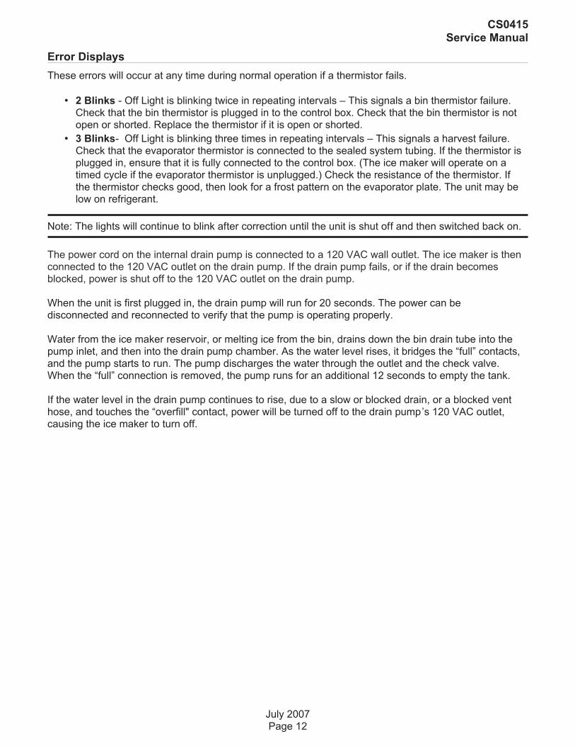
Error Displays
These errors will occur at any time during normal operation if a thermistor fails.
• 2 Blinks - Off Light is blinking twice in repeating intervals – This signals a bin thermistor failure.Check that the bin thermistor is plugged in to the control box. Check that the bin thermistor is notopen or shorted. Replace the thermistor if it is open or shorted.
• 3 Blinks- Off Light is blinking three times in repeating intervals – This signals a harvest failure.Check that the evaporator thermistor is connected to the sealed system tubing. If the thermistor isplugged in, ensure that it is fully connected to the control box. (The ice maker will operate on atimed cycle if the evaporator thermistor is unplugged.) Check the resistance of the thermistor. Ifthe thermistor checks good, then look for a frost pattern on the evaporator plate. The unit may below on refrigerant.
Note: The lights will continue to blink after correction until the unit is shut off and then switched back on.
The power cord on the internal drain pump is connected to a 120 VAC wall outlet. The ice maker is thenconnected to the 120 VAC outlet on the drain pump. If the drain pump fails, or if the drain becomesblocked, power is shut off to the 120 VAC outlet on the drain pump.
When the unit is first plugged in, the drain pump will run for 20 seconds. The power can bedisconnected and reconnected to verify that the pump is operating properly.
Water from the ice maker reservoir, or melting ice from the bin, drains down the bin drain tube into thepump inlet, and then into the drain pump chamber. As the water level rises, it bridges the “full” contacts,and the pump starts to run. The pump discharges the water through the outlet and the check valve.When the “full” connection is removed, the pump runs for an additional 12 seconds to empty the tank.
If the water level in the drain pump continues to rise, due to a slow or blocked drain, or a blocked venthose, and touches the “overfill" contact, power will be turned off to the drain pump’s 120 VAC outlet,causing the ice maker to turn off.
July 2007Page 12
CS0415Service Manual
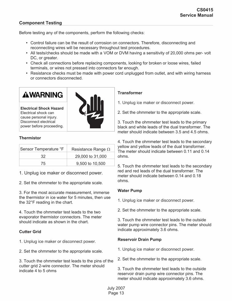
Component Testing
Before testing any of the components, perform the following checks:
• Control failure can be the result of corrosion on connectors. Therefore, disconnecting andreconnecting wires will be necessary throughout test procedures.
• All tests/checks should be made with a VOM or DVM having a sensitivity of 20,000 ohms per- voltDC, or greater.
• Check all connections before replacing components, looking for broken or loose wires, failedterminals, or wires not pressed into connectors far enough.
• Resistance checks must be made with power cord unplugged from outlet, and with wiring harnessor connectors disconnected.
Thermistor
Sensor Temperature °F Resistance Range �
32 29,000 to 31,000
75 9,500 to 10,500
1. Unplug ice maker or disconnect power.
2. Set the ohmmeter to the appropriate scale.
3. For the most accurate measurement, immersethe thermistor in ice water for 5 minutes, then usethe 32°F reading in the chart.
4. Touch the ohmmeter test leads to the twoevaporator thermistor connectors. The metershould indicate as shown in the chart.
Cutter Grid
1. Unplug ice maker or disconnect power.
2. Set the ohmmeter to the appropriate scale.
3. Touch the ohmmeter test leads to the pins of thecutter grid 2-wire connector. The meter shouldindicate 4 to 5 ohms
Transformer
1. Unplug ice maker or disconnect power.
2. Set the ohmmeter to the appropriate scale.
3. Touch the ohmmeter test leads to the primaryblack and white leads of the dual transformer. Themeter should indicate between 3.5 and 4.5 ohms.
4. Touch the ohmmeter test leads to the secondaryyellow and yellow leads of the dual transformer.The meter should indicate between 0.11 and 0.14ohms.
5. Touch the ohmmeter test leads to the secondaryred and red leads of the dual transformer. Themeter should indicate between 0.14 and 0.18ohms.
Water Pump
1. Unplug ice maker or disconnect power.
2. Set the ohmmeter to the appropriate scale.
3. Touch the ohmmeter test leads to the outsidewater pump wire connector pins. The meter shouldindicate approximately 3.6 ohms.
Reservoir Drain Pump
1. Unplug ice maker or disconnect power.
2. Set the ohmmeter to the appropriate scale.
3. Touch the ohmmeter test leads to the outsidereservoir drain pump wire connector pins. Themeter should indicate approximately 3.6 ohms.
July 2007Page 13
CS0415Service Manual
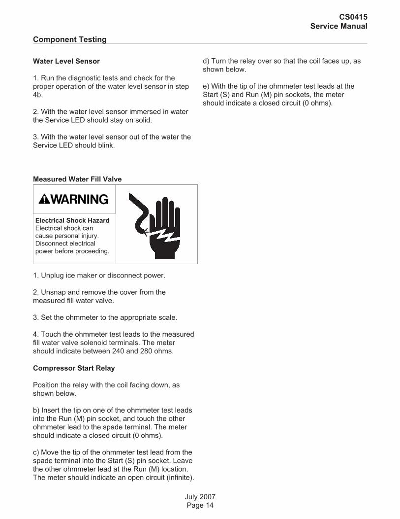
Electrical Shock HazardElectrical shock cancause personal injury.Disconnect electricalpower before proceeding.
Water Level Sensor
1. Run the diagnostic tests and check for theproper operation of the water level sensor in step4b.
2. With the water level sensor immersed in waterthe Service LED should stay on solid.
3. With the water level sensor out of the water theService LED should blink.
Measured Water Fill Valve
1. Unplug ice maker or disconnect power.
2. Unsnap and remove the cover from themeasured fill water valve.
3. Set the ohmmeter to the appropriate scale.
4. Touch the ohmmeter test leads to the measuredfill water valve solenoid terminals. The metershould indicate between 240 and 280 ohms.
Compressor Start Relay
Position the relay with the coil facing down, asshown below.
b) Insert the tip on one of the ohmmeter test leadsinto the Run (M) pin socket, and touch the otherohmmeter lead to the spade terminal. The metershould indicate a closed circuit (0 ohms).
c) Move the tip of the ohmmeter test lead from thespade terminal into the Start (S) pin socket. Leavethe other ohmmeter lead at the Run (M) location.The meter should indicate an open circuit (infinite).
d) Turn the relay over so that the coil faces up, asshown below.
e) With the tip of the ohmmeter test leads at theStart (S) and Run (M) pin sockets, the metershould indicate a closed circuit (0 ohms).
July 2007Page 14
CS0415Service Manual
Electrical Shock HazardElectrical shock cancause personal injury.Disconnect electricalpower before proceeding.
Component Testing
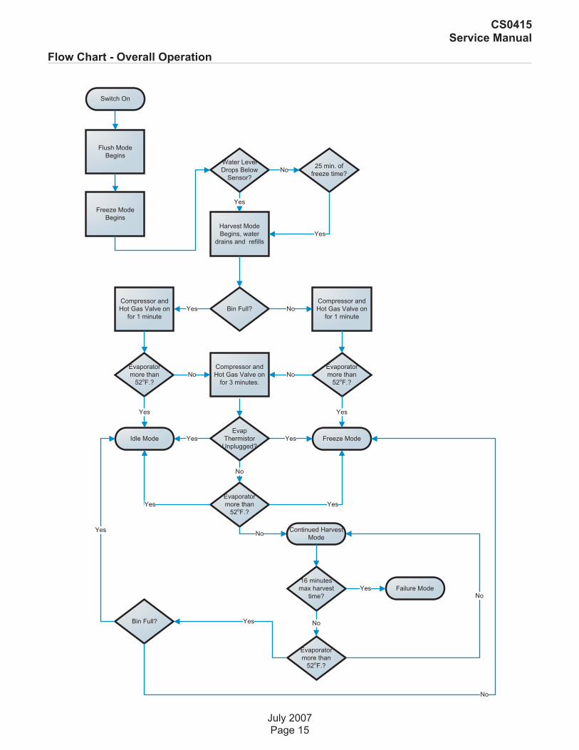
Flow Chart - Overall Operation
July 2007Page 15
CS0415Service Manual
Switch On
Flush Mode
Begins
Freeze Mode
Begins
Harvest Mode
Begins, water
drains and refills
Water Level
Drops Below
Sensor?
25 min. of
freeze time?
Yes
No
Yes
Compressor and
Hot Gas Valve on
for 1 minute
Bin Full?Yes
Compressor and
Hot Gas Valve on
for 1 minute
No
Evaporator
more than
52oF.?
Compressor and
Hot Gas Valve on
for 3 minutes.
No
Freeze ModeIdle Mode
Yes
Evaporator
more than
52oF.?
Yes
Evaporator
more than
52oF.?
No
Yes
Yes
Evap
Thermistor
Unplugged?
No
Yes Yes
NoContinued Harvest
Mode
Evaporator
more than
52oF.?
16 minutes
max harvest
time?
No
Failure ModeYes
Bin Full? Yes
Yes
No
No

Flow Chart - Freeze Mode Details
July 2007Page 16
CS0415Service Manual
Freeze Mode
Water Level
Sensor
Detected?
Comp., fan motor,
spray pump are on
Water level
drops below
sensor?
Comp., fan motor,
spray pump are on
for 25 minutes
maximum
Comp., fan motor,
spray pump are on
Yes No
Harvest Mode
Hung Slab Noted
Yes
No
Water level
drops below
sensor?
Yes
20 minutes up?
No
YesNo
5 minutes up?
Yes
No
Service Diagnosis
July 2007Page 17
CS0415Service Manual
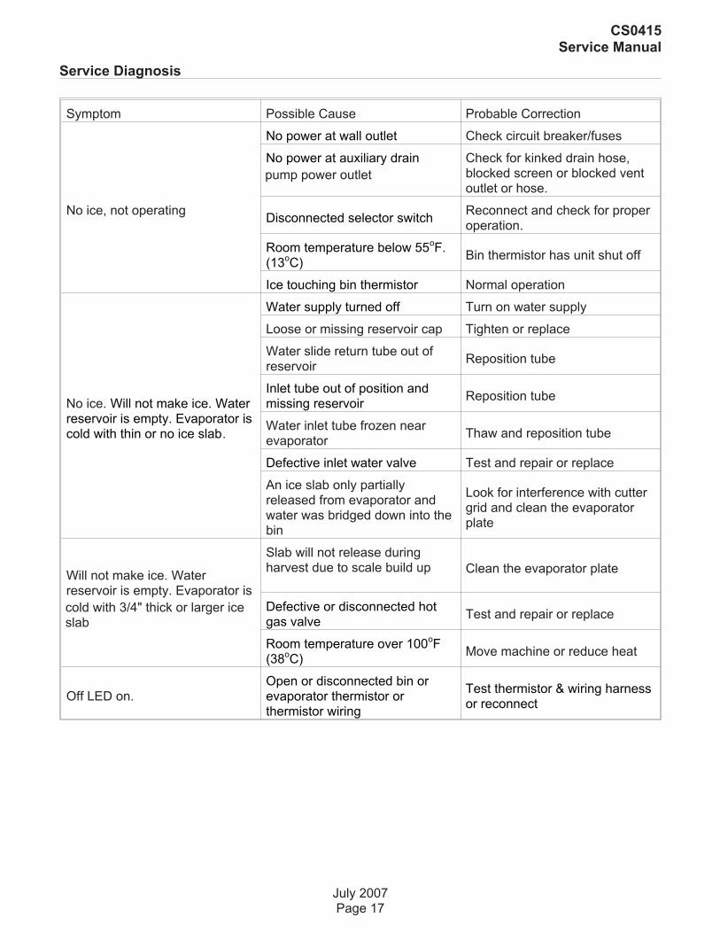
Symptom Possible Cause Probable Correction
No ice, not operating
No power at wall outlet Check circuit breaker/fuses
No power at auxiliary drain
pump power outlet
Check for kinked drain hose,blocked screen or blocked ventoutlet or hose.
Disconnected selector switchReconnect and check for properoperation.
Room temperature below 55oF.
(13oC)
Bin thermistor has unit shut off
Ice touching bin thermistor Normal operation
No ice. Will not make ice. Waterreservoir is empty. Evaporator iscold with thin or no ice slab.
Water supply turned off Turn on water supply
Loose or missing reservoir cap Tighten or replace
Water slide return tube out ofreservoir
Reposition tube
Inlet tube out of position andmissing reservoir
Reposition tube
Water inlet tube frozen nearevaporator
Thaw and reposition tube
Defective inlet water valve Test and repair or replace
An ice slab only partiallyreleased from evaporator andwater was bridged down into thebin
Look for interference with cuttergrid and clean the evaporatorplate
Will not make ice. Waterreservoir is empty. Evaporator is
cold with 3/4" thick or larger iceslab
Slab will not release duringharvest due to scale build up Clean the evaporator plate
Defective or disconnected hotgas valve
Test and repair or replace
Room temperature over 100oF
(38oC)
Move machine or reduce heat
Off LED on.Open or disconnected bin orevaporator thermistor orthermistor wiring
Test thermistor & wiring harnessor reconnect

Service Diagnosis
July 2007Page 18
CS0415Service Manual
Symptom Possible Cause Probable Correction
Will not make ice. Waterreservoir is full. Evaporator iscold with thin/partial/irregular orno ice slab
Seeping water valve. Condenseris hot
Replace water valve
Partial refrigerant leak orrestriction (U-shaped slab)
Check for leak/restriction andrepair or replace defectivecomponent
Defective recirculating pumpRepair or replace the pumpmotor assembly
Partially blocked water distributor Clean distributor and evaporator
Will not make ice. Waterreservoir is full. Evaporator iswarm.
Compressor is not runningTest compressor, relay andoverload
Blocked condenser or stalled fanmotor
Clean condenser, repair orreplace motor
Unit is in the startup mode Wait 5 minutes and recheck
Low capacity
Room temperature below 55oF
(13oC)
Bin thermistor has unit shut off.Advise user.
Seeping water valve. Condenseris hot
Replace water valve
Slow or defective drain or drainpump causing water to back upinto the bin
Repair or replace drain or drainpump
Airflow blocked Remove blockage
Control in extended cycle modeGo to manual test 9, if clean lightis blinking, push Clean buttononce.
Too much ice in bin Defective bin thermistor Test and replace thermistor
Noise
Banging soundThe slab dropping off the plateand ice dropping from the cuttergrid into an empty bin are normalsounds
Grinding, cavitating sound.
The reservoir is empty. Look fora partially released slab,
interference with cutter grid etcand clean the evaporator plate.
Grinding, cavitating sound from
recirculating pump
If the reservoir is full replace thepump
Noisy drain pump Repair or replace
Ice freezing together in the bin Normal if little ice is used. Use more ice.

Removal and Replacement - Thermistor
Bin Thermistor and / Or Cutter Grid
1. Unplug ice maker or disconnect power.
2. Open the ice maker door.
3. Cover or remove the ice from the storage bin.
4. Place a cloth in the drain hole to avoid hardwarefrom falling inside.
5. Remove the two hex-head screws from thecutter grid cover and remove the cover.
6. To remove the bin thermistor:
a) Disconnect the bin thermistor connector from thebottom of the control housing.
b) Pull the bin thermistor out of the retaining clampand remove it.
7. To remove the cutter grid:
a) Disconnect the cutter grid and bin thermistorconnectors from the bottom of the control housing.
b) Remove the two hex-head screws from bothsides of the cutter grid. The longer screw and whitespacer are on the right side.
Slide the cutter grid forward and out of the unit andplace it on a work surface.
Be careful not to scratch the ice maker liner.
d) Remove the spacer from the right cutter gridbracket tab.
Unsnap the two ice guides from the cutter gridtabs. There should be a slight outward tilt after theguides are installed. Bend the metal tabs outward ifnecessary.
July 2007Page 19
CS0415Service Manual
Electrical Shock HazardElectrical shock cancause personal injury.Disconnect electricalpower before proceeding.
Cutter Grid
Control Housing
ConnectorBin Thermostat
Cutter GridConnector
Cutter GridScrews

To remove the evaporator thermistor:
a) Remove the cutter grid from the unit
b) Disconnect the evaporator thermistor connectorfrom the bottom of the control housing.
c) Remove the two hex-head mounting screwsfrom the water trough and pull thetrough from the unit.
Reach behind the accumulator,and unclip the evaporatorthermistor from the evaporatortubing and remove it.
To remove the water distributor:
a) Remove the cutter grid from the unit
b) Pull out on the left and right water distributorretainers, and remove the tabs from the slots in theevaporator. Pull the distributor forward and removethe water hose.
July 2007Page 20
CS0415Service Manual
Water Distributor
Removal and Replacement
EvaporatorThermistor
Water Hose
Tab
1. Unplug ice maker or disconnect power.
2. Open the ice maker door.
3. Cover or remove the ice from the storage bin.
4. Remove the cutter grid cover and the cutter grid.
5. Disconnect the remaining two connectors (binand evaporator thermistors) from the bottom of thecontrol housing.
6. Remove the four hex-head screws from thecontrol housing and lower the housing so that youcan access the components.
NOTE: The control housing components consist of:
• (1) Electronic control board
• (2) Dual transformer
• (3) Light switch
• (4) Push-button switch assembly
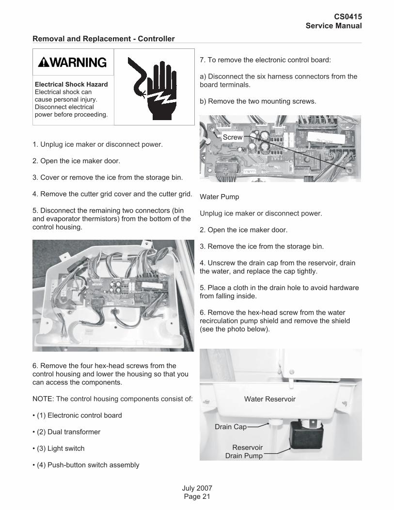
7. To remove the electronic control board:
a) Disconnect the six harness connectors from theboard terminals.
b) Remove the two mounting screws.
Water Pump
Unplug ice maker or disconnect power.
2. Open the ice maker door.
3. Remove the ice from the storage bin.
4. Unscrew the drain cap from the reservoir, drainthe water, and replace the cap tightly.
5. Place a cloth in the drain hole to avoid hardwarefrom falling inside.
6. Remove the hex-head screw from the waterrecirculation pump shield and remove the shield(see the photo below).
July 2007Page 21
CS0415Service Manual
Removal and Replacement - Controller
Electrical Shock HazardElectrical shock cancause personal injury.Disconnect electricalpower before proceeding.
Screw
Water Reservoir
ReservoirDrain Pump
Drain Cap

7. Disconnect the water fill tube from the pumpmounting bracket.
8. Disconnect the two wire pump connectors fromthe harness block.
9. Remove the two thumbscrews from the reservoirand remove the reservoir from the ice maker.
10. Remove the pump outlet tube.
11. Remove three hex-headed screws from thepump mounting bracket and remove pumpassembly.
12. Separate the recirculation pump from thebracket.
Reservoir Drain Pump and /or Water Level Sensor
1. Unplug ice maker or disconnect power.
2. Open the ice maker door.
3. Unscrew the drain cap from the reservoir, drainthe water, and replace the cap tightly.
4. Remove the recirculating pump cover hexheadscrew.
5. To remove reservoir drain pump:
a) Disconnect the reservoir drain pump electricalconnection.
b) Remove the pump retaining screw and bracket.
c) Rotate the pump 1/4 turn and pull it down andout of reservoir.
6. To remove the water level sensor:
a) Disconnect the water level sensor electricalconnection.
b) Remove the retaining clips, if present.
c) Pull the sensor up and out of the bracket.
July 2007Page 22
CS0415Service Manual
Removal and Replacement
Electrical Shock HazardElectrical shock cancause personal injury.Disconnect electricalpower before proceeding.
Water FillTube
Pump OutletTube
Water LevelSensor

Evaporator
1. Unplug ice maker or disconnect power.
2. Open the ice maker door.
3. Remove the ice from the storage bin.
4. Remove the cutter grid and the evaporatorthermistor from the unit.
5. Disconnect the bin thermistor connector from thebottom of the control housing.
6. Remove the top door screw from the ice makerdoor, and pull the door off the bottom hinge.
7. Remove the two 5/16” hex-head screws from thetop hinge and remove the hinge.
8. Remove the two front and two rear screws fromthe cabinet top.
Lift the cabinet top and position it forward on top ofthe unit.
From the rear of the unit, remove the six hex-headscrews from the channel cover and remove thecover.
12. Remove the four screws from the unitcompartment cover and remove the cover.
13. Cut the tie wrap from around the tubing andwire harness inside the channel.
July 2007Page 23
CS0415Service Manual
Removal and Replacement - Evaporator
Electrical Shock HazardElectrical shock cancause personal injury.Disconnect electricalpower before proceeding.
UnitCompartment
Cover
ChannelCover
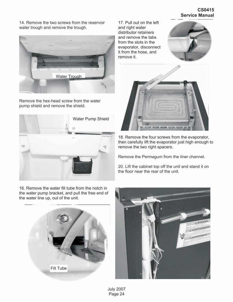
14. Remove the two screws from the reservoirwater trough and remove the trough.
Remove the hex-head screw from the waterpump shield and remove the shield.
16. Remove the water fill tube from the notch inthe water pump bracket, and pull the free end ofthe water line up, out of the unit.
17. Pull out on the leftand right waterdistributor retainersand remove the tabsfrom the slots in theevaporator, disconnectit from the hose, andremove it.
18. Remove the four screws from the evaporator,then carefully lift the evaporator just high enough toremove the two right spacers.
Remove the Permagum from the liner channel.
20. Lift the cabinet top off the unit and stand it onthe floor near the rear of the unit.
July 2007Page 24
CS0415Service Manual
Water Trough
Water Pump Shield
Fill Tube

21. Lift the evaporator and its connecting tubinghigh enough from the unit to access the tubingunderneath.
Access the sealed system and discharge therefrigerant into an approved recovery system.
IMPORTANT: Refrigerant lines must be connectedby a licensed, EPA certified refrigerant technicianin accordance with established procedures.
23. Unbraze (and cut) the evaporator from thetubing at the following locations:
• Suction line at the compressor.
• Hot gas line at the hot gas valve.
• Cut capillary tube at the drier fi lt
REASSEMBLY NOTES:
When installing the new evaporator, use agenerous amount of thermal heat trap pastebetween the hot gas valve, and the evaporatortubing joint to protect the hot gas valve whenbrazing.
• Be sure to reinstall the Permagum in the linerchannel of the cabinet around the wire sheath andtubing, so that there are no air leaks after thecabinet top is installed
July 2007Page 25
CS0415Service Manual

SCOTSMAN ICE SYSTEMS
775 Corporate Woods Parkway, Vernon Hills, IL 60061
800-533-6006
www.scotsman-ice.com
17-3187-01