Starter 9/1/09 p 53 # 7 Time to finish starter. Starter 9/2/09 p 53 #’s 1-5 Time to finish starter.
Upload
nguyendienCategory
view
223download
0
SERVICE MANUAL
STARTER 2100 Bench pH Meter STARTER 3100 Bench pH Meter
STARTER 3100C Bench pH Meter STARTER 3100M Bench pH and Conductivity Meter
Ohaus Corporation, 7 Campus Drive, Suite 310, Parsippany, NJ 07054 (973) 377-9000

SERVICE MANUAL
STARTER 2100 Bench pH Meter STARTER 3100 Bench pH Meter
STARTER 3100C Bench pH Meter STARTER 3100M Bench pH and Conductivity Meter
The information contained in this manual is believed to be accurate at the time of publication, but Ohaus Corporation assumes no liability arising from the use or misuse of this material. Reproduction of this material is strictly prohibited.
Material in this manual is subject to change.
© Copyright 2016 Ohaus Corporation, all rights reserved. ® Registered trademark of Ohaus Corporation.

TABLE OF CONTENTS
Ohaus Corporation www.ohaus.com i Starter Series Bench Meter Service Manual
Page No.
CHAPTER 1 GETTING STARTED 1.1 Introduction ...............................................................................................................1-1 1.2 Definition of Signal Words and Symbol ……………………………………………….1-1 1.3 Safety Precaution ………………………………………………………………………..1-2
1.4 Service Facilities ......................................................................................................1-1 1.5 Tools and Test Equipment Required ........................................................................1-1 1.6 Specifications ...........................................................................................................1-2 1.7 Meter Operation Starter 2100 ...................................................................................1-3 1.7.1 Overview of the Controls …....................................................................................1-3 1.8 Meter Operation Starter 3100 ...................................................................................1-5 1.8.1 Overview of the Controls .......................................................................................1-5 1.9 Meter Operation Starter 3100C ................................................................................1-7 1.9.1 Overview of the Controls .......................................................................................1-7 1.10 Meter Operation Starter 3100M ………………………………………………………1-x 1.10.1 Overview of the Controls …………………………………………………………….1-x
CHAPTER 2 MAINTENANCE PROCEDURES 2.1 Preventive Maintenance ...........................................................................................2-1 2.2 Service Strategy .......................................................................................................2-1 2.3 Opening the Meter ....................................................................................................2-1 2.2.1 Separating the Top and Bottom Housings .............................................................2-1 2.4 Removing/Replacing the Main Printed Circuit Board (PCB) .....................................2-2
CHAPTER 3 RESET TO FACTORY SETTINGS 3.1. Recover Factory Settings .........................................................................................3-1
CHAPTER 4 DRAWINGS AND PARTS LISTS 4-1 Starter 2100 Scale: Housing & Internal Parts ................................................................4-2 4-2 Starter 3100 Scale: Housing & Internal Parts ................................................................4-3 4-3 Starter 3100C Scale: Housing & Internal Parts .............................................................4-3 4-4 Starter 3100M Scale: Housing & Internal Parts ………………………………………….4-4
LIST OF TABLES TABLE NO. TITLE Page No.
1-1 Specifications .................................................................................................................1-2 1-2 Starter 2100 Controls Functions ....................................................................................1-4 1-3 Starter 3100 Controls Functions ....................................................................................1-6 1-4 Starter 3100C Controls Functions .................................................................................1-8 3-1 Mounting Bolt Torque Settings ......................................................................................3-5 3-2 Overload Stop Gap Settings ..........................................................................................3-6 4-1 Housing & Internal Parts ................................................................................................4-1

TABLE OF CONTENTS
Starter Series Bench Meter Service Manual ii Ohaus Corporation www.ohaus.com
LIST OF ILLUSTRATIONS FIGURE NO. TITLE
1-1 Starter 2100 Display ......................................................................................................1-3 1-2 Starter 3100 Display ......................................................................................................1-5 1-3 Starter 3100C Display ...................................................................................................1-7 2-1 Screws securing Top Housing .......................................................................................2-1 2-2 Main Printed Curcuit Board ...........................................................................................2-2 4-1 Housing & Internal Parts ...............................................................................................4-2 4-2 Housing & Internal Parts ...............................................................................................4-3 4-3 Housing & Internal Parts ...............................................................................................4-4

CHAPTER 1 GETTING STARTED
Starter Series Bench Meter Service Manual 1-1 Ohaus Corporation www.ohaus.com
1.1 INTRODUCTION
This service manual contains the information needed to perform routine maintenance and service on the Ohaus Starter Bench Series portable meters. Familiarity with the meter’s Instruction Manual is assumed. The contents of this manual are contained in four chapters:
Chapter 1 Getting Started – Contains information on service facilities, tools and test equipment, specifications, and the mechanical and electronic functions of the meter.
Chapter 2 Maintenance Procedures – Contains preventive maintenance procedures and disassembly, repair and replacement procedures.
Chapter 3 Reset to factory settings – Explains procedures for resetting the meter to factory default settings.
Chapter 4 Drawings and Parts Lists – Contains exploded views of the products identifying all serviceable components.
Note: Content in this manual are subject to changes without notice.
1.2 DEFINITION OF SIGNAL WORDS AND SYMBOLS.
Safety notes are marked with signal words and warning symbols. These show safety issues and warnings. Ignoring the safety notes may lead to personal injury, damage to the instrument, malfunctions and false results.
Signal Words
CAUTION For a hazardous situation with low risk, resulting in damage to the device or the property or in loss of data, or injuries if not avoided.
Attention For important information about the product.
Note For useful information about the product.
Warning Symbols
General Hazard Electrostatic discharge sensitive

CHAPTER 1 GETTING STARTED
Ohaus Corporation www.ohaus.com 1-2 Starter Series Bench Meter Service Manual
1.3 SAFETY PRECAUTIONS.
Service should only be performed by authorized personnel.
Use electrostatic protection measures when handling the printed circuit board.
Remove the AAA batteries before cleaning or servicing the equipment.
Operate the equipment only under ambient conditions specified in the userinstructions.
Do not operate the equipment in hazardous or unstable environments.
This equipment is intended for indoor use and should only be operated in drylocations.
Only use original replacement parts and accessories.
1.4 SERVICE FACILITIES
To service a meter, the service area should meet the following requirements:
Should be temperature controlled and meet meter specifications for temperatureenvironmental requirements.
Area must be clean and free of excessive dust.
Work surface must be stable and level.
Meter must not be exposed to direct sunlight or radiating heat sources.
Use an approved Electro-Static Device.
1.5 TOOLS AND TEST EQUIPMENT REQUIRED
Service should contain the following equipment: 1. Standard hand tools.2. Digital Voltmeter (DVM).3. Standard Electronics tool kit.4. Grounding mat and clip.5. Respective electrodes.6. Respective buffer solution.
CAUTION: Read all safety warnings before installing, making connections, or servicing this equipment. Failure to comply with these warnings could result in personal injury and/or property damage. Retain all instructions for future reference.

CHAPTER 1 GETTING STARTED
Starter Series Bench Meter Service Manual 1-3 Ohaus Corporation www.ohaus.com
1.6 SPECIFICATIONS
Complete specifications for the Ohaus Starter Bench meters are listed in Table 1-1. When a meter has been serviced, it must meet the specifications listed in the table. Before servicing the meter, determine what specifications are not met.
TABLE 1-1. SPECIFICATIONS

CHAPTER 1 GETTING STARTED
Ohaus Corporation www.ohaus.com 1-4 Starter Series Bench Meter Service Manual
Spec. ST3100M
Measurement Range
pH –2.00…20.00 pH
mV –2000…+2000mV
Conductivity 0.0 μS/cm…199.9mS/cm
TDS 0.1mg/l…199.9 g/l(TDS)
Resistivity 0…20MΩ•cm
Salinity 0-100 psu
Temperature -5°C…110 °C
Resolution
pH 0.01pH
mV 1mV
Conductivity 0.01 μS/cm Auto range
TDS 0.01 mg/L Auto range
Resistivity 0.01 Ω•cm Auto range
Salinity 0.01 psu
Temperature 0.1 °C
Error Limits/Accuracy
pH ± 0.01 pH
mV ± 1mV
Conductivity etc.
± 0.5 %F.S.
Temperature ± 0.3 °C
Calibration
pH Up to 3 point, 6 buffer groups
Conductivity 5 predefined conductivity standard points
Memory 99 sets pH and 99 sets conductivity data, last calibration data
Power/Battery AC Adapter Input: 100-240V ~ X.XA 50/60 Hz
AC Adapter Output: 12V X.XA
Size/weight Approximately 220 W x 175 D x 78 H mm / 0.95 kg
Display LCD with backlight
CHAPTER 1 GETTING STARTED
Starter Series Bench Meter Service Manual 1-5 Ohaus Corporation www.ohaus.com
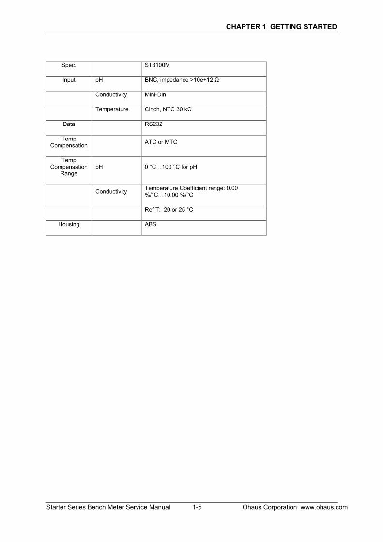
Spec. ST3100M
Input pH BNC, impedance >10e+12 Ω
Conductivity Mini-Din
Temperature Cinch, NTC 30 kΩ
Data RS232
Temp Compensation
ATC or MTC
Temp Compensation
Range pH 0 °C…100 °C for pH
Conductivity Temperature Coefficient range: 0.00 %/°C…10.00 %/°C
Ref T: 20 or 25 °C
Housing ABS

CHAPTER 1 GETTING STARTED
Ohaus Corporation www.ohaus.com 1-6 Starter Series Bench Meter Service Manual
1.7 METER OPERATION – STARTER 2100
This section contains information on the basic operation of the Starter 2100 meter.
1.7.1 OVERVIEW OF THE CONTROLS
Displays
Figure 1-1. Starter 2100 display
1 Electrode condition
Slope: more than 95%
and offset: ± (0-15) mV
Electrode condition is
good
Slope: 90-95%
or offset: ± (15-35) mV
Electrode condition is
acceptable
Slope: less than 90%
or offset: ± (35-60) mV
Electrode condition is not good
or needs cleaning
2 Measurement icon - ; measurement or calibration is running
3 Calibration icon - Cal ; 1 point or 2 point calibration in progress
4 pH/mV reading or slope (%) in calibration
5 Error message- Err
6 Auto temperature compensation - ATC ; Manual temperature compensation - MTC
7 Temperature during measurement of Offset (mV) in calibration
CHAPTER 1 GETTING STARTED
Starter Series Bench Meter Service Manual 1-7 Ohaus Corporation www.ohaus.com

CHAPTER 1 GETTING STARTED
Ohaus Corporation www.ohaus.com 1-8 Starter Series Bench Meter Service Manual
1.8 METER OPERATION – ST3100
This section contains information on the basic operation of the ST3100 meter.
1.8.1 OVERVIEW OF THE CONTROLS
Displays
Figure 1-2. ST3100 display

CHAPTER 1 GETTING STARTED
Starter Series Bench Meter Service Manual 1-9 Ohaus Corporation www.ohaus.com
TABLE 1-3. Control functions ST3100

CHAPTER 1 GETTING STARTED
Ohaus Corporation www.ohaus.com 1-10 Starter Series Bench Meter Service Manual
1.9 METER OPERATION – ST3100C
This section contains information on the basic operation of the Starter 3100C meter.
1.9.1 OVERVIEW OF THE CONTROLS
Displays
Figure 1-3. ST3100C display

CHAPTER 1 GETTING STARTED
Starter Series Bench Meter Service Manual 1-11 Ohaus Corporation www.ohaus.com
TABLE 1-4. Control functions ST3100C
CHAPTER 1 GETTING STARTED
Ohaus Corporation www.ohaus.com 1-12 Starter Series Bench Meter Service Manual
1.10 METER OPERATION – ST3100M
This section contains information on the basic operation of the Starter 3100M meter.
1.10.1 OVERVIEW OF THE CONTROLS
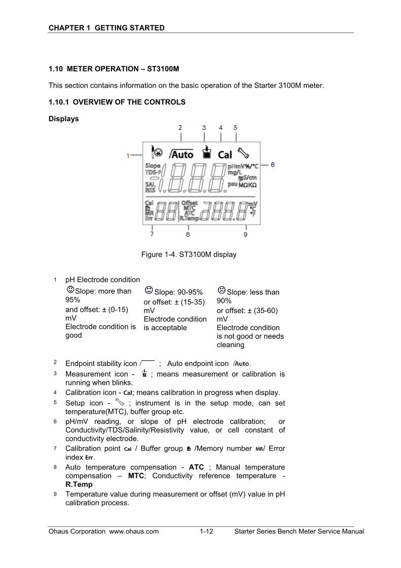
Displays
Figure 1-4. ST3100M display
1 pH Electrode condition
Slope: more than 95%
and offset: ± (0-15) mV Electrode condition is good
Slope: 90-95%
or offset: ± (15-35) mV Electrode condition is acceptable
Slope: less than 90%
or offset: ± (35-60) mV Electrode condition is not good or needs cleaning
2 Endpoint stability icon ; Auto endpoint icon . 3 Measurement icon - ; means measurement or calibration is
running when blinks.
4 Calibration icon - ; means calibration in progress when display.
5 Setup icon - ; instrument is in the setup mode, can set temperature(MTC), buffer group etc.
6 pH/mV reading, or slope of pH electrode calibration; or Conductivity/TDS/Salinity/Resistivity value, or cell constant of conductivity electrode.
7 Calibration point / Buffer group /Memory number / Error
index . 8 Auto temperature compensation - ATC ; Manual temperature
compensation – MTC; Conductivity reference temperature - R.Temp
9 Temperature value during measurement or offset (mV) value in pH calibration process.

CHAPTER 1 GETTING STARTED
Starter Series Bench Meter Service Manual 1-13 Ohaus Corporation www.ohaus.com
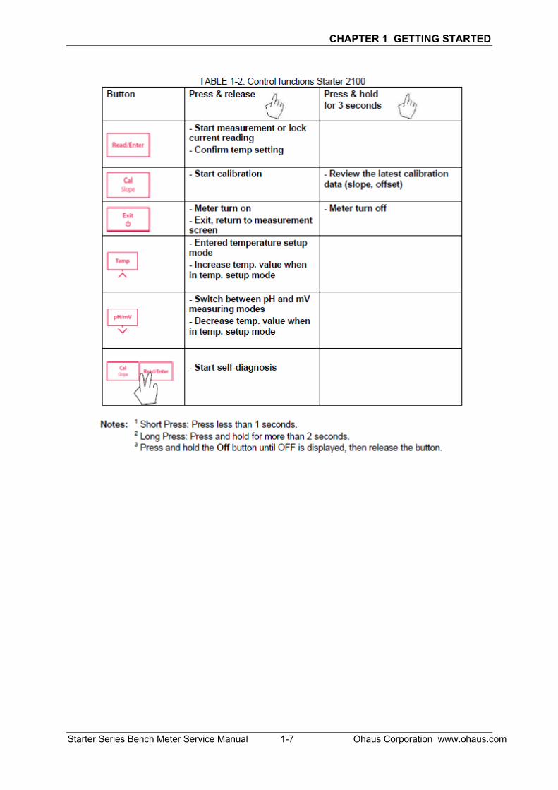
TABLE 1-5. Control functions ST3100M
Button Press & release Press & hold
for 3 seconds
- Switch between pH(mV)
parameter and
conductivity(TDS/Salinity/Resisti
vity) parameter when at
measurement interface
- Start or finish measurement
- Confirm setting, store entered
value
- Turn auto endpoint on / off
,
- Start calibration - Recall the latest calibration
data : slope and offset
- Meter turn on
- Exit and return to measurement
screen
- Meter turn off
- Store current reading to memory
- Increase value during setting
- Scroll up through the memory
- Recall stored data
- Print current memory data
- Switch between pH and mV
- Decrease value during setting
- Scroll down through the memory
- Enter setup mode
- Start self-diagnosis
Turn on/turn off the backlight
of the LCD

CHAPTER 2 MAINTENANCE PROCEDURES
Starter Series Bench Meter Service Manual 2-1 Ohaus Corporation www.ohaus.com
2.1 PREVENTIVE MAINTENANCE
Ohaus meters are precision instruments and should be carefully handled, stored in a clean, dry, dust-free area, and cleaned periodically.
Cleaning the meter housing can be done by using a cloth dampened with mild detergent if necessary.
Do not use solvents, chemicals, alcohol, ammonia or abrasives to clean the housing or control panel.
2.2 SERVICE STRATEGY
All parts of the Starter Bench Top Series are designed to be replaced rather than repaired. This includes the Main Printed Circuit Board (PCB). For an illustrated list of replaceable parts, see Chapter 4.
2.3 OPENING THE METER
Use these procedures in order to replace the Printed Circuit Board and the cables, if applicable.
2.3.1 Separating the Top and Bottom Housings
Common hand tools are sufficient to disassemble the products. Turn the meter off and unplug the power cord before you begin.
1. Turn the meter over. Remove the four screws holding the Housing in place.
2. Separate Top Housing fromBottom Housing. Avoid strainingthe cables that connect the MainPCB on the bottom housing tothe parts in the top Housing.(Lay the two housings close toeach other, so cable is notstrained.)
CAUTION: Observe precaution for handling electrostatic sensitive deceives.
Figure 2-1. Screws (marked with white circles) that secure the housing.

CHAPTER 2 MAINTENANCE PROCEDURES
Ohaus Corporation www.ohaus.com 2-2 Starter Series Bench Meter Service Manual
2.4 Removing/Replacing the PCB
If the PCB are suspected to be faulty, it should be replaced, as follows:
1. Disconnect the Cable connecting the PCB to the meter’s control buttons.
2. For ST3100M loosen the control button cable connector in order to isolate the top housing away from the bottom housing.
3. Remove the four screws that secure the PCB to the bottom housing (Fig 2-2).
4. Lift out the PCB.
5. Position the replacement PCB.
6. Re-connect the Top housing Cable to the PCB, in the same position as originally installed.
7. Insert and tighten the screws that secure the PCB to the bottom housing.
CAUTION: Observe precaution for handling electrostatic sensitive deceives.
Figure 2-2. Main Printed Circuit Board with display.

CHAPTER 3 RESET TO FACTORY SETTINGS
Starter Series Bench Meter Service Manual 3-1 Ohaus Corporation www.ohaus.com
3.1 Recover factory settings
When the meter is off, press and hold button-Read & button-Cal & button-Exit together for 3 seconds, the screen displays and blinks, means “Reset”. Then we have 2 choice:
Press button-Read to reset factory settings (MTC, slope and offset, etc.), display then restart the meter. Or press button-Exit to quit the setting, display then turn off the meter.

CHAPTER 4 RESET TO FACTORY SETTINGS
Ohaus Corporation www.ohaus.com 3-2 Starter Series Bench Meter Service Manual
3.2 Error message
3.2.1 Error message ST2100
3.2.2 Error message ST3100
TABLE 3-1. ST2100 Error Message.
TABLE 3-2. ST3100 Error Message.

CHAPTER 3 RESET TO FACTORY SETTINGS
Starter Series Bench Meter Service Manual 3-3 Ohaus Corporation www.ohaus.com
3.2.3 Error message ST3100C
TABLE 3-3. ST3100C Error Message.

CHAPTER 4 RESET TO FACTORY SETTINGS
Ohaus Corporation www.ohaus.com 3-4 Starter Series Bench Meter Service Manual
3.2.4 Error message ST3100M
When ST3100M as pH meter:
Error 0 Memory access error
Reset to factory settings
Error 1 Self-diagnosis failed
Repeat the self-diagnosis procedure and make sure that you finish pressing all five keys within two minutes
Error 2 Measured values out of range
Check if the electrode is properly connected and placed in the sample solution.
Error 3 Measured buffer temperature out of range (<5 or >40 °C)
Keep the pH buffer temperature within the range for calibration
Error 4 Offset out of range
offset > 60mV or < - 60 mV
Make sure the pH buffer is correct and fresh; Clean or replace the pH electrode.
Error 5 Slope out of range
Make sure the buffer is correct and fresh; Clean or replace the pH electrode.
Error 6 Meter cannot recognize the buffer
Make sure the buffer is correct and fresh; check if the buffer has not been used more than once.
Error 9 The current data set has already been stored once
An endpoint reading can only be stored once. Perform a new measurement to store.
Error 10 The sample temperature out of range
Check the sample temperature, the temperature sensor.
TABLE 3-4. ST3100M Error Message as pH Meter.
CHAPTER 3 RESET TO FACTORY SETTINGS
Starter Series Bench Meter Service Manual 3-5 Ohaus Corporation www.ohaus.com
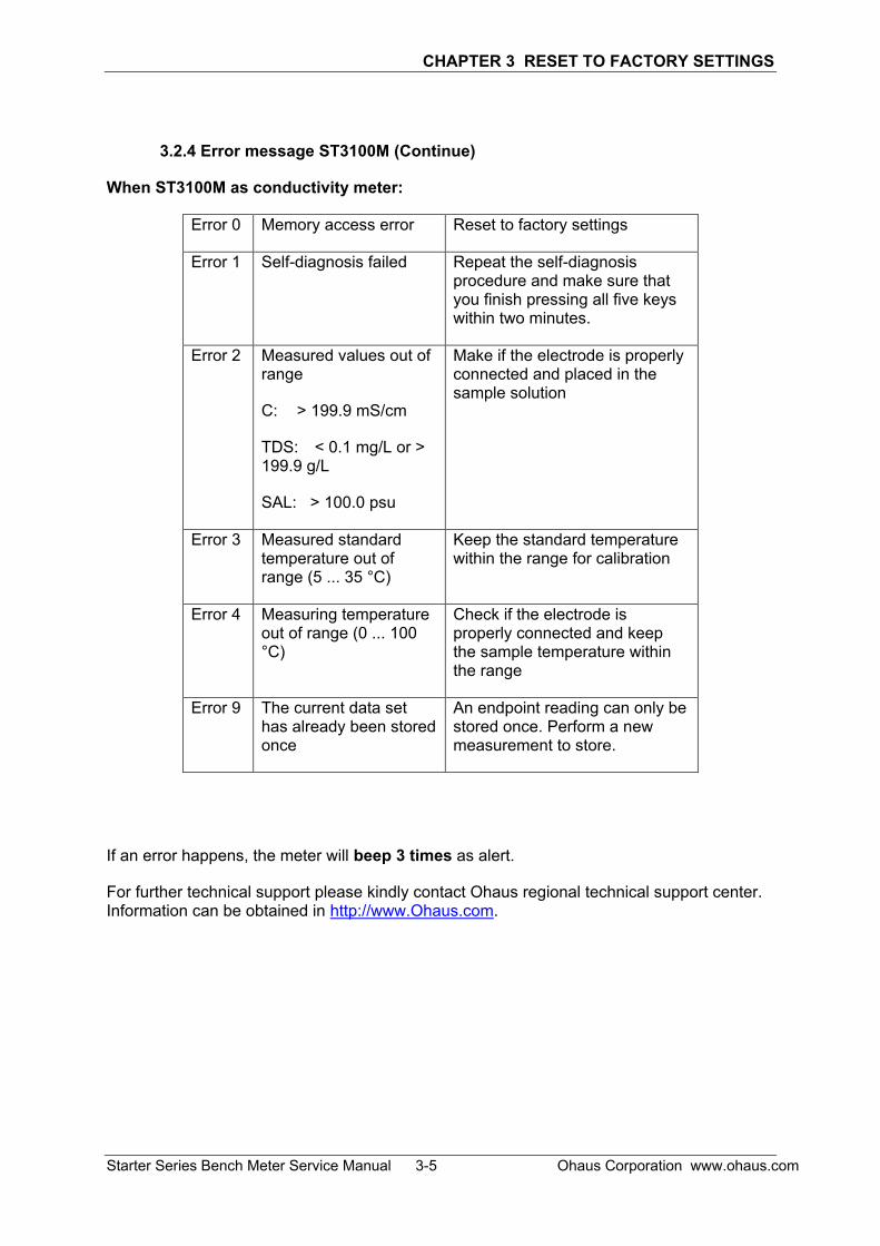
3.2.4 Error message ST3100M (Continue)
When ST3100M as conductivity meter:
Error 0 Memory access error Reset to factory settings
Error 1 Self-diagnosis failed Repeat the self-diagnosis procedure and make sure that you finish pressing all five keys within two minutes.
Error 2 Measured values out of range
C: > 199.9 mS/cm
TDS: < 0.1 mg/L or > 199.9 g/L
SAL: > 100.0 psu
Make if the electrode is properly connected and placed in the sample solution
Error 3 Measured standard temperature out of range (5 ... 35 °C)
Keep the standard temperature within the range for calibration
Error 4 Measuring temperature out of range (0 ... 100 °C)
Check if the electrode is properly connected and keep the sample temperature within the range
Error 9 The current data set has already been stored once
An endpoint reading can only be stored once. Perform a new measurement to store.
If an error happens, the meter will beep 3 times as alert.
For further technical support please kindly contact Ohaus regional technical support center. Information can be obtained in http://www.Ohaus.com.

CHAPTER 4 PARTS LISTS & DIAGRAMS
Starter Series Bench Meter Service Manual 4-1 Ohaus Corporation www.ohaus.com
This section of the manual contains exploded views of the products. The exploded view drawings are designed to identify the parts which can be serviced.
NOTE: Attention: After any hardware replacement, the product must be thoroughly checked. The product MUST meet the parameters of all applicable specifications in this manual.
Step to confirm the meter operates within specification:
1. Obtain a known good working condition electrode and buffer solution in hand.
2. Link the electrode to the portable meter, perform a calibration after completed the calibration do a measurement and compare with the meter specification.
If further technical information is needed, please contact your local Ohaus distributor, or: www.ohaus.com Ohaus Corporation 7 Campus Drive Suite 310 Parsippany, NJ 07054 USA Tel: +1 973-377-9000 Fax: +1 973-593-0359 In the United States call toll free, 800-526-0659 between 8:00 a.m. and 6:00 p.m. EST.

CHAPTER 4 PARTS LISTS & DIAGRAMS
Ohaus Corporation www.ohaus.com 4-2 Starter Series Bench Meter Service Manual
4.1 Starter Series Bench Meter: PARTS
Figure 4-1. Starter Series Bench Meter: Parts.
TABLE 4-1 Starter Series Bench Meter: PARTS
Drawing Item Description
1 Acc, In use cover 2 SP Overlay EN, ZH 3 SP PCBA 4 SP Screw and feet set for Starter Bench
5 Acc Electrode holder stand alone Note: For parts numbers, see your local Ohaus distributor, or visit www.ohaus.com.


*30332138B* P/N 30332138B SERVICE MANUAL: Starter Bench Top Series