
SERVICE MANUAL - Diagramas dediagramas.diagramasde.com/televisores/Zenith H20H52DT_Service... ·...
48
SERVICE MANUAL SERVICE MANUAL Product Type: Chassis: Manual Part #: Model Line: Product Year: Model Number: CONTENTS General Information/Remote Controls................................ Installer’s Menu ............................................................ Servicing/Trobleshooting ................................................ ................................................. Exploded Views ............................................................. Schematics ................................................................... Model/Module Parts List Published by Technical Publications Zenith Electronics Corporation P. O. Box 240007 Huntsville, Al 35824 Copyright December 2004 by Zenith Electronics Corporation © Printed in U. S. A. Presentation Series FCH-50 3828VD0205B H 2004 1 2 3 4 5 6 H20H52DT H20H52DT8 HW20H52DT HW20H52DT11
-
Upload
vuongquynh -
Category
Documents
-
view
232 -
download
0
Transcript of SERVICE MANUAL - Diagramas dediagramas.diagramasde.com/televisores/Zenith H20H52DT_Service... ·...
SERVICE MANUAL SERVICE MANUAL
Product Type: Chassis: Manual Part #: Model Line: Product Year:
Model Number:
CONTENTSGeneral Information/Remote Controls................................Installer’s Menu ............................................................Servicing/Trobleshooting ................................................
.................................................Exploded Views ............................................................. Schematics ...................................................................
Model/Module Parts List
Published by Technical Publications
Zenith Electronics CorporationP. O. Box 240007
Huntsville, Al 35824
Copyright December 2004 by Zenith Electronics Corporation ©
Printed in U. S. A.
Presentation SeriesFCH-503828VD0205BH2004
123456
H20H52DTH20H52DT8HW20H52DTHW20H52DT11
PRODUCT SAFETY SERVICING GUIDELINES FOR AUDIO-VIDEO PRODUCTS
3828VD0205B CH-FLAT - SAFETYi
IMPORTANT SAFETY NOTICEThis Manual was prepared for use only by properly trained audio-visual servicetechnicians.When servicing this product, under no circumstances should the original designbe modified or altered without permission from Zenith Electronics Corporation.All components should be replaced only with types identical to those in theoriginal circuit and their physical location, wiring and lead dress must conformto original layout upon completion of repairs.
Special components are also used to prevent x-radiation, shock and fire hazard.These components are indicated by the letter “x” included in their componentdesignators and are required to maintain safe performance. No deviations areallowed without prior approval by Zenith Electronics Corporation.
Circuit diagrams may occasionally differ from the actual circuit used. This way,implementation of the latest safety and performance improvement changes intothe set is not delayed until the new service literature is printed.
Caution: Do not attempt to modify this product in any way. Never performcustomized installations without manufacturer’s approval. Unauthorizedmodifications will not only void the warranty, but may lead to property damageor user injury.
Service work should be performed only after you are thoroughly familiar withthese safety checks and servicing guidelines.
Graphic symbols
The exclamation point within an equilateral triangle is intendedto alert the service personnel to important safety information inthe service literature.
The lightning flash with arrowhead symbol within an equilateraltriangle is intended to alert the service personnel to the presenceof noninsulated “dangerous voltage” that may be of sufficientmagnitude to constitute a risk of electric shock.
The pictorial representation of a fuse and its rating within anequilateral triangle is intended to convey to the servicepersonnel the following fuse replacement caution notice:CAUTION: FOR CONTINUED PROTECTION AGAINST RISK OF FIRE,REPLACE ALL FUSES WITH THE SAME TYPE AND RATING AS MARKEDNEAR EACH FUSE.
SERVICE INFORMATIONWhile servicing, use an isolation transformer for protection from AC line shock.
After the original service problem has been corrected, make a check of thefollowing:
FIRE AND SHOCK HAZARD1. Be sure that all components are positioned to avoid a possibility of
adjacent component shorts. This is especially important on items transportedto and from the repair shop.
2. Verify that all protective devices such as insulators, barriers, covers, shields,strain reliefs, power supply cords, and other hardware have been reinstalledper the original design. Be sure that the safety purpose of the polarized lineplug has not been defeated.
3. Soldering must be inspected to discover possible cold solder joints, soldersplashes, or sharp solder points. Be certain to remove all loose foreignparticles.
4. Check for physical evidence of damage or deterioration to parts andcomponents, for frayed leads or damaged insulation (including the ACcord), and replace if necessary.
5. No lead or component should touch a receiving tube or a resistor rated at1 watt or more. Lead tension around protruding metal surfaces must beavoided.
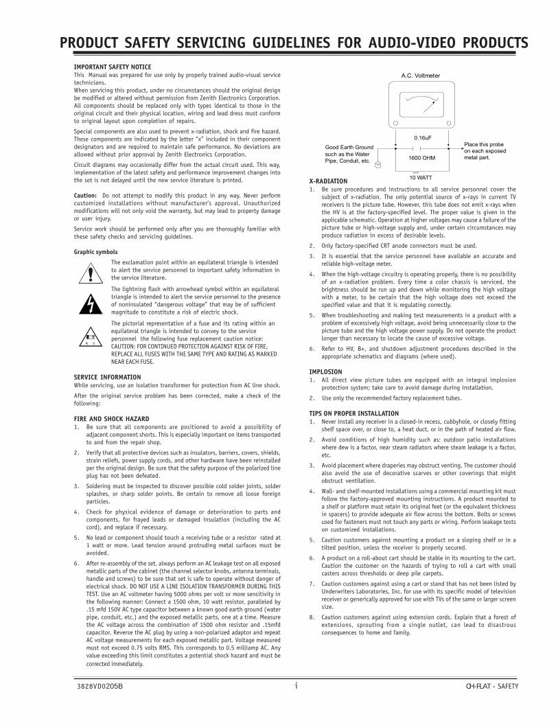
6. After re-assembly of the set, always perform an AC leakage test on all exposedmetallic parts of the cabinet (the channel selector knobs, antenna terminals,handle and screws) to be sure that set is safe to operate without danger ofelectrical shock. DO NOT USE A LINE ISOLATION TRANSFORMER DURING THISTEST. Use an AC voltmeter having 5000 ohms per volt or more sensitivity inthe following manner: Connect a 1500 ohm, 10 watt resistor, paralleled by.15 mfd 150V AC type capacitor between a known good earth ground (waterpipe, conduit, etc.) and the exposed metallic parts, one at a time. Measurethe AC voltage across the combination of 1500 ohm resistor and .15mfdcapacitor. Reverse the AC plug by using a non-polarized adaptor and repeatAC voltage measurements for each exposed metallic part. Voltage measuredmust not exceed 0.75 volts RMS. This corresponds to 0.5 milliamp AC. Anyvalue exceeding this limit constitutes a potential shock hazard and must becorrected immediately.
X-RADIATION1. Be sure procedures and instructions to all service personnel cover the
subject of x-radiation. The only potential source of x-rays in current TVreceivers is the picture tube. However, this tube does not emit x-rays whenthe HV is at the factory-specified level. The proper value is given in theapplicable schematic. Operation at higher voltages may cause a failure of thepicture tube or high-voltage supply and, under certain circumstances mayproduce radiation in excess of desirable levels.
2. Only factory-specified CRT anode connectors must be used.
3. It is essential that the service personnel have available an accurate andreliable high-voltage meter.
4. When the high-voltage circuitry is operating properly, there is no possibilityof an x-radiation problem. Every time a color chassis is serviced, thebrightness should be run up and down while monitoring the high voltagewith a meter, to be certain that the high voltage does not exceed thespecified value and that it is regulating correctly.
5. When troubleshooting and making test measurements in a product with aproblem of excessively high voltage, avoid being unnecessarily close to thepicture tube and the high voltage power supply. Do not operate the productlonger than necessary to locate the cause of excessive voltage.
6. Refer to HV, B+, and shutdown adjustment procedures described in theappropriate schematics and diagrams (where used).
IMPLOSION1. All direct view picture tubes are equipped with an integral implosion
protection system; take care to avoid damage during installation.
2. Use only the recommended factory replacement tubes.
TIPS ON PROPER INSTALLATION1. Never install any receiver in a closed-in recess, cubbyhole, or closely fitting
shelf space over, or close to, a heat duct, or in the path of heated air flow.
2. Avoid conditions of high humidity such as: outdoor patio installationswhere dew is a factor, near steam radiators where steam leakage is a factor,etc.
3. Avoid placement where draperies may obstruct venting. The customer shouldalso avoid the use of decorative scarves or other coverings that mightobstruct ventilation.
4. Wall- and shelf-mounted installations using a commercial mounting kit mustfollow the factory-approved mounting instructions. A product mounted toa shelf or platform must retain its original feet (or the equivalent thicknessin spacers) to provide adequate air flow across the bottom. Bolts or screwsused for fasteners must not touch any parts or wiring. Perform leakage testson customized installations.
5. Caution customers against mounting a product on a sloping shelf or in atilted position, unless the receiver is properly secured.
6. A product on a roll-about cart should be stable in its mounting to the cart.Caution the customer on the hazards of trying to roll a cart with smallcasters across thresholds or deep pile carpets.
7. Caution customers against using a cart or stand that has not been listed byUnderwriters Laboratories, Inc. for use with its specific model of televisionreceiver or generically approved for use with TVs of the same or larger screensize.
8. Caution customers against using extension cords. Explain that a forest ofextensions, sprouting from a single outlet, can lead to disastrousconsequences to home and family.
A.C. Voltmeter
1600 OHM
10 WATT
Place this probeon each exposedmetal part.
Good Earth Groundsuch as the WaterPipe, Conduit, etc.
0.16uF
PRODUCT SAFETY SERVICING GUIDELINES FOR AUDIO-VIDEO PRODUCTS
3828VD0205B CH-FLAT - SAFETYii
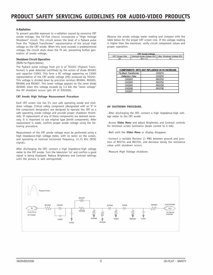
X-RadiationTo prevent possible exposure to x-radiation caused by excessive CRTanode voltage, the CH-Flat chassis incorporate a “High VoltageShutdown” circuit. This circuit senses the level of a flyback pulsefrom the “Flyback Transformer” representative of the actual highvoltage on the CRT anode. When this level exceeds a predeterminedvoltage, the circuit shuts down the TV set, preventing further gen-eration of anode voltage.
Shutdown Circuit Operation(Refer to Figure below)The flyback pulse voltage from pin 6 of TX3201 (Flyback Trans-former) is peak detected (rectified) by the action of diode DX3001and capacitor C3003. This form a DC voltage appearing on C3003representative of the CRT anode voltage (HV) produced by TX3201.This voltage is divided down by precision resistors RX3004, RX3005,RX3006 and RX3007. This lower voltage appears on the zener diodeZD3000; when this voltage exceeds by 3.5 Vdc the “zener voltage”the HV shutdown occurs (pin 29 of ICX2200).
CRT Anode High Voltage Measurement Procedure
Each CRT screen size has it’s own safe operating anode and shut-down voltage. Critical safety component (designated with an ‘X’ inthe component designator) are designed to operate the CRT at asafe operating anode voltage and provide proper shutdown thresh-olds. If replacement of any of these components are deemed neces-sary, it is important to use original type Zenith components. Afterreplacement is made, confirm proper anode voltage using the fol-lowing procedure.
Measurement of the CRT anode voltage must be performed using ahigh impedance-high voltage meter, with no raster on the screen,and operating at nominal horizontal frequency, 15.75 Khz (NTSCsignal).
After discharging the CRT, connect a high impedance-high voltagemeter to the CRT anode. Turn the television ‘on’ and confirm a goodsignal is being displayed. Reduce Brightness and Contrast settingsuntil the picture is well extinguished.
Observe the anode voltage meter reading and compare with thetable below for the proper CRT screen size. If the voltage readingis higher than the maximum, verify circuit component values andproper operation.
CRT Screen Size Nominal Anode Voltage (KV) Max. Shutdown Voltage (KV)20" 26+/-1.0 32
CRT Anode Voltage
HV SHUTDOWN PROCEDURE.
·After discharging the CRT, connect a high impedance-high volt-age meter to the CRT anode
·Access Video Menu and adjust Brightness and Contrast controlsfor minimum screen luminance (beam current to 0 mA).
·Wait until the Video Menu or display disappear.
·Connect a variable Resistor (1 MW) between ground and junc-tion of RX3754 and RX3755, and decrease slowly the resistancevalue until shutdown occurs.
·Measure High Voltage shutdown.
Fly-Back Transformer CX3215Deflection Yoke CX3216
CX3203 RX3753CX3204 RX3754CX3205 RX3755CX3206 RX3756CX3207
COMPONENTS WITH ANY INFLUENCE IN HV INCREASE
Flyback Pulse
IN
RX3209
C3003
DX3001
RX3007
RX3006
RX3005
C3002
ZD3000
R3003
D3002
RM3002 C3001
RM3001 SHUTDOWN
TO PIN 29ICX2200Of TX3201
From Pin 6
OUT
RX3004
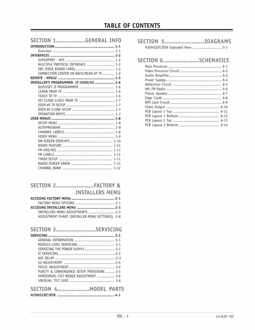
TABLE OF CONTENTS
SECTION 1.................GENERAL INFOINTRODUCTION...................................................... 1-1
Overview ........................................................ 1-1INTERFACES .......................................................... 1-2
SUPERPORT - MPI ............................................ 1-2MULTIPLE PROTOCOL INTERFACE ......................... 1-2EBC (EDGE BOARD CARD) ................................... 1-2CONNECTION CENTER ON BACK/REAR OF TV........... 1-2
REMOTE - HP602 ................................................... 1-5INSTALLER’S PROGRAMMER LT-2000/02 .................. 1-6
QUICKSET II PROGRAMMER ................................ 1-6LEARN FROM TV ............................................... 1-6TEACH TO TV ................................................... 1-6SET CLONE CLOCK FROM TV ................................ 1-7DISPLAY TV SETUP ............................................ 1-7DISPLAY CLONE SETUP ...................................... 1-7OPERATION NOTES ............................................ 1-7
USER MENUS ......................................................... 1-8SETUP MENU ................................................... 1-8AUTOPROGRAM................................................. 1-8CHANNEL LABELS ............................................. 1-8VIDEO MENU ................................................... 1-9ON SCREEN DISPLAYS ...................................... 1-10RADIO FEATURE ............................................. 1-11FM ADD/DEL ................................................. 1-11FM LABELS .................................................... 1-11TIMER SETUP ................................................. 1-11RADIO SCREEN SAVER ..................................... 1-11CHANNEL BANK ............................................. 1-12
SECTION 2......................FACTORY & INSTALLERS MENUACCESING FACTORY MENU ....................................... 2-1
FACTORY MENU OPTIONS ................................... 2-1ACCESING INSTALLERS MENU .................................. 2-3
INSTALLERS MENU ADJUSTMENTS ........................ 2-3ADJUSTMENT CHART (INSTALLER MENU SETTINGS) . 2-8
SECTION 3.......................SERVICINGSERVICING ............................................................ 3-1
GENERAL INFORMATION..................................... 3-1MODULE-LEVEL SERVICING ................................. 3-1SERVICING THE POWER SUPPLY ........................... 3-1IF SERVICING....................................................3-3AGC DELAY .......................................................3-3G2 ADJUSTMENT ...............................................3-4FOCUS ADJUSTMENT ......................................... 3-4PURITY & CONVERGENCE SETUP PROCEDURE ........ 3-5HORIZONTAL-TILT WEDGE ADJUSTMENT ................ 3-6UNUSUAL TILT CASE ......................................... 3-6
SECTION 4..................MODEL PARTSH20H52DT/DT8 ....................................................4-1
TOC - 1 CH-FLAT -TOC
SECTION 5......................DIAGRAMSH20H52DT/DT8 Exploded View .......................... 5-1
SECTION 6.....................SCHEMATICSMain Processor ................................................ 6-1Video Processor Circuit ..................................... 6-2Audio Amplifier ............................................... 6-3Power Supply .................................................. 6-4Deflection Circuit ............................................ 6-5AM_FM Radio .................................................. 6-6Pillow Speaker ................................................ 6-7Edge Cardt ..................................................... 6-8MPI Card Circuit .............................................. 6-9Video Output ................................................ 6-10PCB Layout 1 Top .......................................... 6-11PCB Layout 1 Bottom ..................................... 6-12PCB Layout 2 Top .......................................... 6-13PCB Layout 2 Bottom ..................................... 6-14
3828VD0205B 1-1 CH-FLAT - OVERVIEW
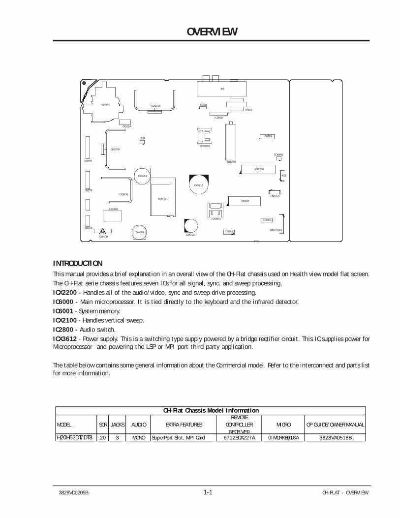
OVERVIEW
INTRODUCTIONThis manual provides a brief explanation in an overall view of the CH-Flat chassis used on Health view model flat screen.The CH-Flat serie chassis features seven ICs for all signal, sync, and sweep processing.ICX2200 - Handles all of the audio/video, sync and sweep drive processing.IC6000 - Main microprocessor. It is tied directly to the keyboard and the infrared detector.IC6001 - System memory.ICX2100 - Handles vertical sweep.IC2800 - Audio switch.ICX3612 - Power supply. This is a switching type supply powered by a bridge rectifier circuit. This IC supplies power forMicroprocessor and powering the LSP or MPI port third party application.
The table below contains some general information about the Commercial model. Refer to the interconnect and parts listfor more information.
4G9
CN2K6CX4003
CN2C5B
IC6000
ICX2200
CON4H2
ICX3850
IC2800
TU1240
CN10VGA1
ICX3801
TX3201
CN2C5A
ICX2100
JP1
Qx3200
2H4IC4201
CN3T8
CN3R8
CN3Y3
TX3612
CX3653
IC801
ICX3670
LX3400
IC6001
Tx900
CX3610
FX3400
TX4001
MODEL SCR JACKS AUDIO EXTRA FEATURESREMOTE
CONTROLLER RECEIVER
MICRO OP GUIDE/OWNER MANUAL
H20H52DT/DT8 20 3 MONO SuperPort Slot, MPI Card 6712SCA227A 0IMCRKE018A 3828VA0518B
CH-Flat Chassis Model Information
3828VD0205B 1-2 CH-FLAT - OVERVIEW
OVERVIEW (continued)
INTERFACESSUPERPORT - MPI
Zenith Commercial Product receivers are now beingadapted to interact with other equipment. Prime ex-amples of this can be found in Lodging and Health Caresituations where the set is controlled from the main of-fice.All this is made possible by the new technology that isbeing built into these receivers. The SuperPort and/orMultiple Protocol Interface (MPI) jack and associatedcircuitry allow remote control of the set.
MULTIPLE PROTOCOL INTERFACE
Television functions and features are controlled by thecommunication of commands and status informationthrough a Superport by the MPI interface.
EBC (EDGE BOARD CONNECTOR)
Allows easy access for removing/installing accessorymodules providing a rail mounted slide-through card.These cards might contain one of the above features.
CONNECTION CENTER ON BACK OF TV
The connection on the back of the TV contains the in-put and output interfaces.
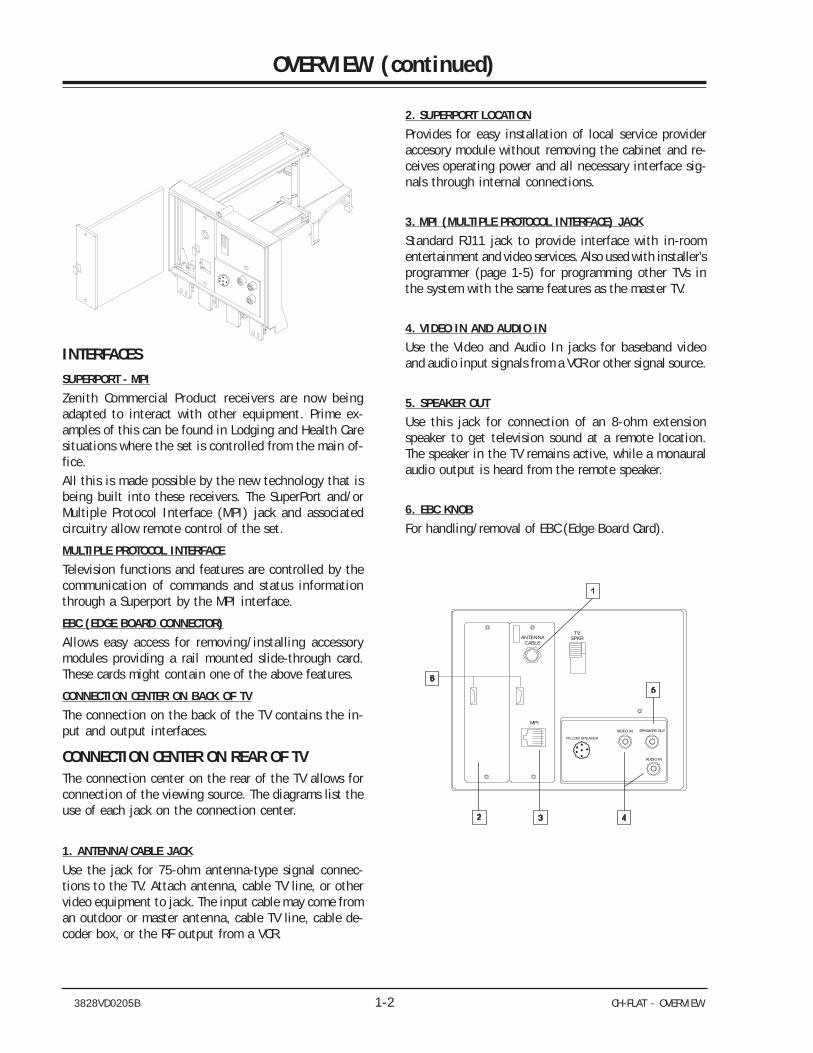
CONNECTION CENTER ON REAR OF TVThe connection center on the rear of the TV allows forconnection of the viewing source. The diagrams list theuse of each jack on the connection center.
1. ANTENNA/CABLE JACK
Use the jack for 75-ohm antenna-type signal connec-tions to the TV. Attach antenna, cable TV line, or othervideo equipment to jack. The input cable may come froman outdoor or master antenna, cable TV line, cable de-coder box, or the RF output from a VCR.
2. SUPERPORT LOCATION
Provides for easy installation of local service provideraccesory module without removing the cabinet and re-ceives operating power and all necessary interface sig-nals through internal connections.
3. MPI (MULTIPLE PROTOCOL INTERFACE) JACK
Standard RJ11 jack to provide interface with in-roomentertainment and video services. Also used with installer’sprogrammer (page 1-5) for programming other TVs inthe system with the same features as the master TV.
4. VIDEO IN AND AUDIO IN
Use the Video and Audio In jacks for baseband videoand audio input signals from a VCR or other signal source.
5. SPEAKER OUT
Use this jack for connection of an 8-ohm extensionspeaker to get television sound at a remote location.The speaker in the TV remains active, while a monauralaudio output is heard from the remote speaker.
6. EBC KNOB
For handling/removal of EBC (Edge Board Card).
VIDEO IN SPEAKER OUT
AUDIO IN
ANTENNACABLE
TVSPKR
PILLOW SPEAKER
MPI
3828VD0205B 1-3 CH-FLAT - OVERVIEW
OVERVIEW (continued)
PILLOW SPEAKER INTERFACE
DESCRIPTION
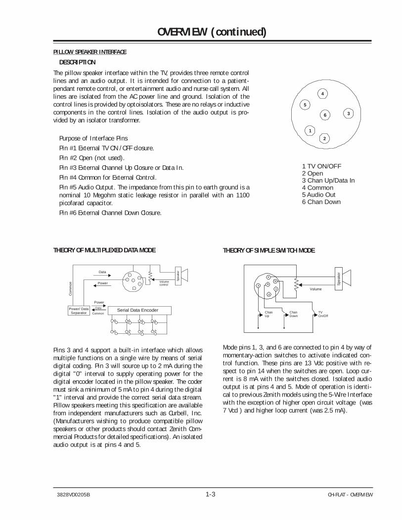
The pillow speaker interface within the TV, provides three remote controllines and an audio output. It is intended for connection to a patient-pendant remote control, or entertainment audio and nurse call system. Alllines are isolated from the AC power line and ground. Isolation of thecontrol lines is provided by optoisolators. These are no relays or inductivecomponents in the control lines. Isolation of the audio output is pro-vided by an isolator transformer.
Purpose of Interface Pins
Pin #1 External TV ON /OFF closure.
Pin #2 Open (not used).
Pin #3 External Channel Up Closure or Data In.
Pin #4 Common for External Control.
Pin #5 Audio Output. The impedance from this pin to earth ground is anominal 10 Megohm static leakage resistor in parallel with an 1100picofarad capacitor.
Pin #6 External Channel Down Closure.
THEORY OF SIMPLE SWITCH MODE
1
2
3
4
56 Sp
eake
r
Volume
ChanUp
ChanDown
TVOn/Off
Mode pins 1, 3, and 6 are connected to pin 4 by way ofmomentary-action switches to activate indicated con-trol function. These pins are 13 Vdc positive with re-spect to pin 14 when the switches are open. Loop cur-rent is 8 mA with the switches closed. Isolated audiooutput is at pins 4 and 5. Mode of operation is identi-cal to previous Zenith models using the 5-Wire Interfacewith the exception of higher open circuit voltage (was7 Vcd ) and higher loop current (was 2.5 mA).
THEORY OF MULTIPLEXED DATA MODE
1
2
3
4
5
6
Power/ Data Separator Serial Data Encoder
Data
Power
PowerData
Common
Spea
ker
Volumecontrol
Com
mon
H H H H
H H H H
Pins 3 and 4 support a built-in interface which allowsmultiple functions on a single wire by means of serialdigital coding. Pin 3 will source up to 2 mA during thedigital "0" interval to supply operating power for thedigital encoder located in the pillow speaker. The codermust sink a minimum of 5 mA to pin 4 during the digital"1" interval and provide the correct serial data stream.Pillow speakers meeting this specification are availablefrom independent manufacturers such as Curbell, Inc.(Manufacturers wishing to produce compatible pillowspeakers or other products should contact Zenith Com-mercial Products for detailed specifications). An isolatedaudio output is at pins 4 and 5.
1 TV ON/OFF2 Open3 Chan Up/Data In4 Common5 Audio Out6 Chan Down
1
2
3
4
5
6
3828VD0205B 1-4 CH-FLAT - OVERVIEW
OVERVIEW (continued)
SETTINGS MIN/MAX VOLUME LEVELSUse the following procedure to adjust minimum volumeand maximum volume for pillow speaker. This procedurenot only sets the maximum volume level that the pillowspeaker can produce, but also prevents the TVs volumefrom accidentally being adjusted to level which is toolow or too loud.
1. Connect pillow speaker. Place INT/EXT speaker switchon back of TV in EXT position.2. Set VOLUME control on pillow speaker to maximumvolume position.3. Access Service Menu by following the instructionsgiven in the “Service Menu” section of this book. Selectthe MAX volume. Use the ADJUST key to set highestdesired volume level within the range of 0 to 63. Thiswill be the highest desired volume level, as heard at thepillow speaker.4. Select the MIN volume. Use the ADJUST key to setthe lowest desired volume level within the range of 0 to63. This will be the lowest desired volume level as heardat the pillow speaker.5. Make no further adjustments and exit the ServiceMenu.
The TV is now adjusted for minimum and maximum vol-ume settings. All further adjustments of the TVs volumeshould be made by using the VOLUME control on thepillow speaker.
3828VD0205B 1-5 CH-FLAT - OVERVIEW
OVERVIEW (continued)
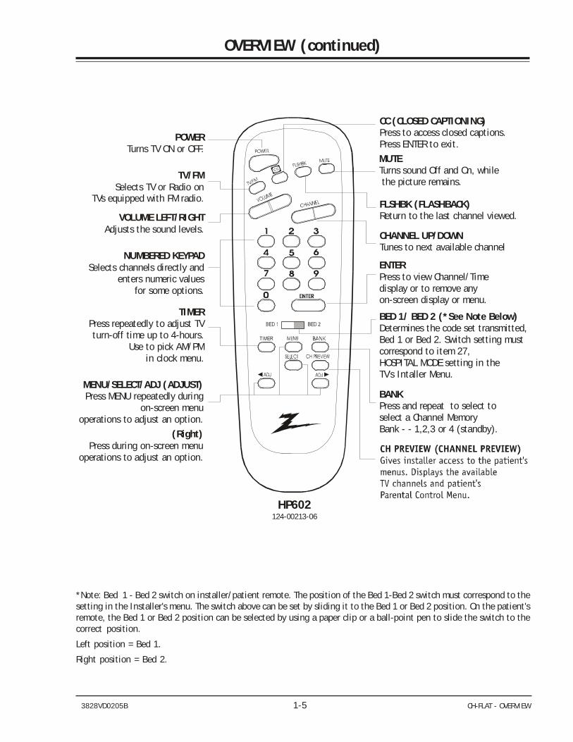
*Note: Bed 1 - Bed 2 switch on installer/patient remote. The position of the Bed 1-Bed 2 switch must correspond to thesetting in the Installer's menu. The switch above can be set by sliding it to the Bed 1 or Bed 2 position. On the patient'sremote, the Bed 1 or Bed 2 position can be selected by using a paper clip or a ball-point pen to slide the switch to thecorrect position.
Left position = Bed 1.
Right position = Bed 2.
POWERTurns TV ON or OFF.
CC (CLOSED CAPTIONING)Press to access closed captions.Press ENTER to exit.
VOLUME LEFT/RIGHTAdjusts the sound levels.
NUMBERED KEYPADSelects channels directly and
enters numeric values for some options.
MUTETurns sound Off and On, while the picture remains.
FLSHBK (FLASHBACK)Return to the last channel viewed.
CHANNEL UP/DOWNTunes to next available channel
BANKPress and repeat to select to select a Channel Memory Bank - - 1,2,3 or 4 (standby).
BED 1/ BED 2 (*See Note Below) Determines the code set transmitted, Bed 1 or Bed 2. Switch setting must correspond to item 27, HOSPITAL MODE setting in the TV's Intaller Menu.
TIMERPress repeatedly to adjust TV turn-off time up to 4-hours.
Use to pick AM/PM in clock menu.
ENTERPress to view Channel/Time d or to remove any on-screen display or isplay
menu.
TV/FM Selects TV or Radio on
TVs equipped with FM radio.
MENU/Press MENU repeatedly during
on-screen menuoperations to adjust an option.
SELECT/ADJ (ADJUST)
(Right)Press during on-screen menu
operations to adjust an option.
CC
HP602124-00213-06
3828VD0205B 1-6 CH-FLAT - OVERVIEW
OVERVIEW (continued)
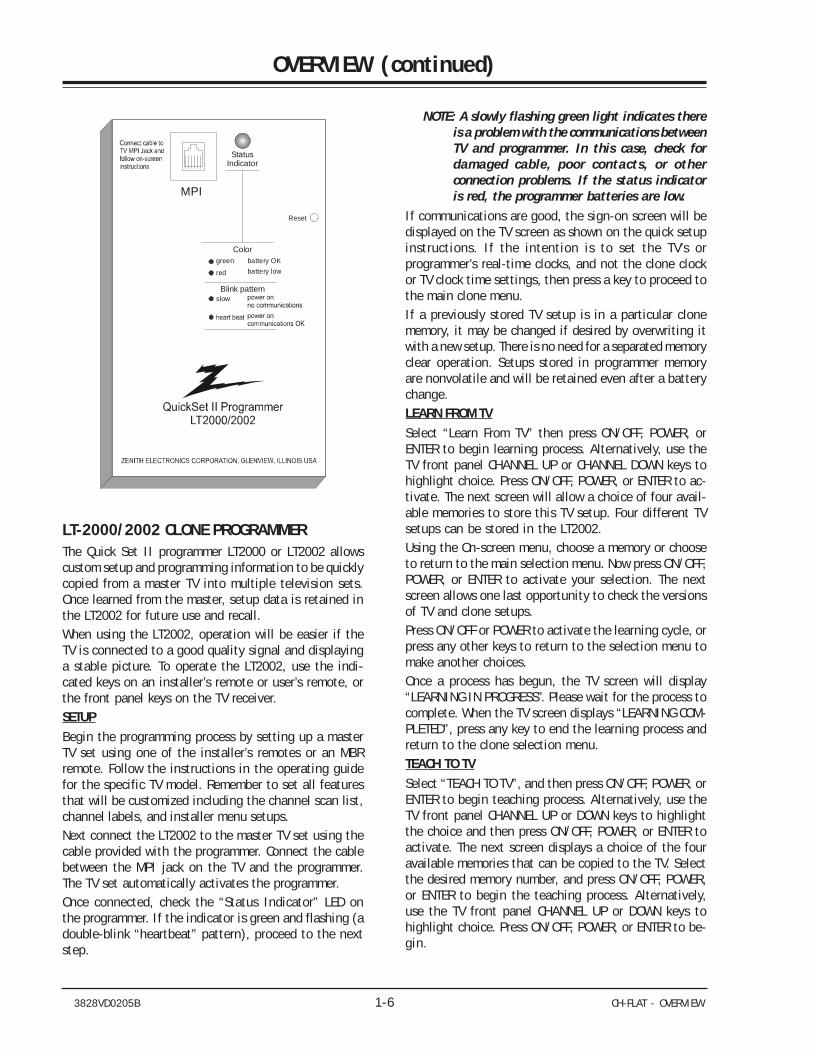
LT-2000/2002 CLONE PROGRAMMERThe Quick Set II programmer LT2000 or LT2002 allowscustom setup and programming information to be quicklycopied from a master TV into multiple television sets.Once learned from the master, setup data is retained inthe LT2002 for future use and recall.When using the LT2002, operation will be easier if theTV is connected to a good quality signal and displayinga stable picture. To operate the LT2002, use the indi-cated keys on an installer’s remote or user’s remote, orthe front panel keys on the TV receiver.SETUPBegin the programming process by setting up a masterTV set using one of the installer’s remotes or an MBRremote. Follow the instructions in the operating guidefor the specific TV model. Remember to set all featuresthat will be customized including the channel scan list,channel labels, and installer menu setups.Next connect the LT2002 to the master TV set using thecable provided with the programmer. Connect the cablebetween the MPI jack on the TV and the programmer.The TV set automatically activates the programmer.Once connected, check the “Status Indicator” LED onthe programmer. If the indicator is green and flashing (adouble-blink “heartbeat” pattern), proceed to the nextstep.
NOTE: A slowly flashing green light indicates thereis a problem with the communications betweenTV and programmer. In this case, check fordamaged cable, poor contacts, or otherconnection problems. If the status indicatoris red, the programmer batteries are low.
If communications are good, the sign-on screen will bedisplayed on the TV screen as shown on the quick setupinstructions. If the intention is to set the TV’s orprogrammer’s real-time clocks, and not the clone clockor TV clock time settings, then press a key to proceed tothe main clone menu.If a previously stored TV setup is in a particular clonememory, it may be changed if desired by overwriting itwith a new setup. There is no need for a separated memoryclear operation. Setups stored in programmer memoryare nonvolatile and will be retained even after a batterychange.LEARN FROM TVSelect “Learn From TV” then press ON/OFF, POWER, orENTER to begin learning process. Alternatively, use theTV front panel CHANNEL UP or CHANNEL DOWN keys tohighlight choice. Press ON/OFF, POWER, or ENTER to ac-tivate. The next screen will allow a choice of four avail-able memories to store this TV setup. Four different TVsetups can be stored in the LT2002.Using the On-screen menu, choose a memory or chooseto return to the main selection menu. Now press ON/OFF,POWER, or ENTER to activate your selection. The nextscreen allows one last opportunity to check the versionsof TV and clone setups.Press ON/OFF or POWER to activate the learning cycle, orpress any other keys to return to the selection menu tomake another choices.Once a process has begun, the TV screen will display“LEARNING IN PROGRESS”. Please wait for the process tocomplete. When the TV screen displays “LEARNING COM-PLETED”, press any key to end the learning process andreturn to the clone selection menu.TEACH TO TVSelect “TEACH TO TV”, and then press ON/OFF, POWER, orENTER to begin teaching process. Alternatively, use theTV front panel CHANNEL UP or DOWN keys to highlightthe choice and then press ON/OFF, POWER, or ENTER toactivate. The next screen displays a choice of the fouravailable memories that can be copied to the TV. Selectthe desired memory number, and press ON/OFF, POWER,or ENTER to begin the teaching process. Alternatively,use the TV front panel CHANNEL UP or DOWN keys tohighlight choice. Press ON/OFF, POWER, or ENTER to be-gin.
StatusIndicator
Color
Blink pattern
battery OKbattery low
green
slow
red
Reset
MPI
3828VD0205B 1-7 CH-FLAT - OVERVIEW
OVERVIEW (continued)Using the on-screen menu, select a memory or return tothe main selection menu. Then press ON/OFF, POWER, orENTER to activate the selection.The next screen allows for one last opportunity to checkthe versions of TV and clone setups. Press ON/OFF orPOWER to activate the teaching cycle, or any other keyto return to the selection menu to make other choices.Once a process has begun, the TV screen will display the“TEACHING IN PROGRESS” message. Please wait for theprocess to complete. When the TV screen displays “TEACH-ING COMPLETED”, press any key to end the teaching pro-cess and return to the clone selection menu.
SET CLONE CLOCK FROM TV
To set the real-time clock in the LT2002, select “SETCLONE FROM TV” and then press ON/OFF, POWER, or EN-TER to copy current TV time to the clone clock. Alterna-tively, use the TV front panel CHANNEL UP or CHANNELDOWN keys to highlight the choice. Then press ON/OFF,POWER, or ENTER to activate.This process will return the LT2002 to the sign-on screento display the clone and TV clock settings. Press a keyto go to the clone selection menu and perform otherfunctions, or simply disconnect if the time setting wasthe last task.SET TV CLOCK FROM CLONETo set the real time clock in the, select “SET TV CLOCKFROM CLONE” and then press ON/OFF, POWER, or ENTERto copy current LT2002 time to the TV clock. Alterna-tively, use the TV front panel CHANNEL UP or CHANNELDOWN keys to highlight the choice. Then press ON/OFF,POWER, or ENTER to activate.This process will return the LT2002 to the sign-on screento display the clone and TV clock settings. Press a keyto go to the clone selection menu and perform otherfunctions, or simply disconnect if the time setting wasthe last task.DISPLAY TV SETUPSelect “DISPLAY TV SETUP”, and then press ON/OFF, POWER,or ENTER to begin the teaching process. Alternatively,use the TV front panel CHANNEL UP or CHANNEL DOWNkeys to highlight your choice. Then press ON/OFF, POWER,or ENTER.The TV screen will display the items in the service menusetups. Use this function to quickly check the TV forcorrect setup. Press any key to clear display and returnto the clone selection menu.DISPLAY CLONE SETUPSelect “DISPLAY CLONE SETUP” and then press ON/OFF,POWER, or ENTER to begin the teaching process. Alter-natively, use the TV front panel CHANNEL UP or CHANNEL
DOWN keys to highlight the choice, then press ON/OFF,POWER, or ENTER to begin.The TV screen will display the memory selection menu.Select the desired memory number, and then press ON/OFF, POWER, or ENTER to display the contents of theselected memory. Alternatively, use the TV’s CHANNEL UPor CHANNEL DOWN keys to highlight the choice, thenpress ON/OFF, POWER, or ENTER to begin.The TV screen will display items in the factory menu setup.Use this function to quickly check contents of a par-ticular clone memory for correct setup. Press any key toclear the display and return to the clone selection menu.
OPERATION NOTESDisconnect the LT2002 from the TV set when the desiredtask has been completed. Disconnecting the clone au-tomatically switches it off. The real time clock contin-ues to run when the main circuits are switched off.After replacing exhausted batteries, or if the program-mer behaves strangely after a static shock, use a paperclip or similar instrument inserted through the small holemarked “RESET” to activate the internal reset switch andrestore normal operation. After reset, check the real-timeclock setting. It may be necessary to reset the clockfrom a TV programmed to the correct time.
The specific microprocessor used in any TV set may bedetermined by activating the service menu. The micro-processor part number appears at the top of the screenwith the service menu is activated. Processors beforethe 221-01006 has limited screen display capability. Theycannot display entire screens as shown in the quick setupinstructions accompanying the LT2002 programmer. Usethe printed menu illustrations on the quick setup sheetas an aid in making programming choices.
3828VD0205B 1-8 CH-FLAT - MENUS
USER MENUS
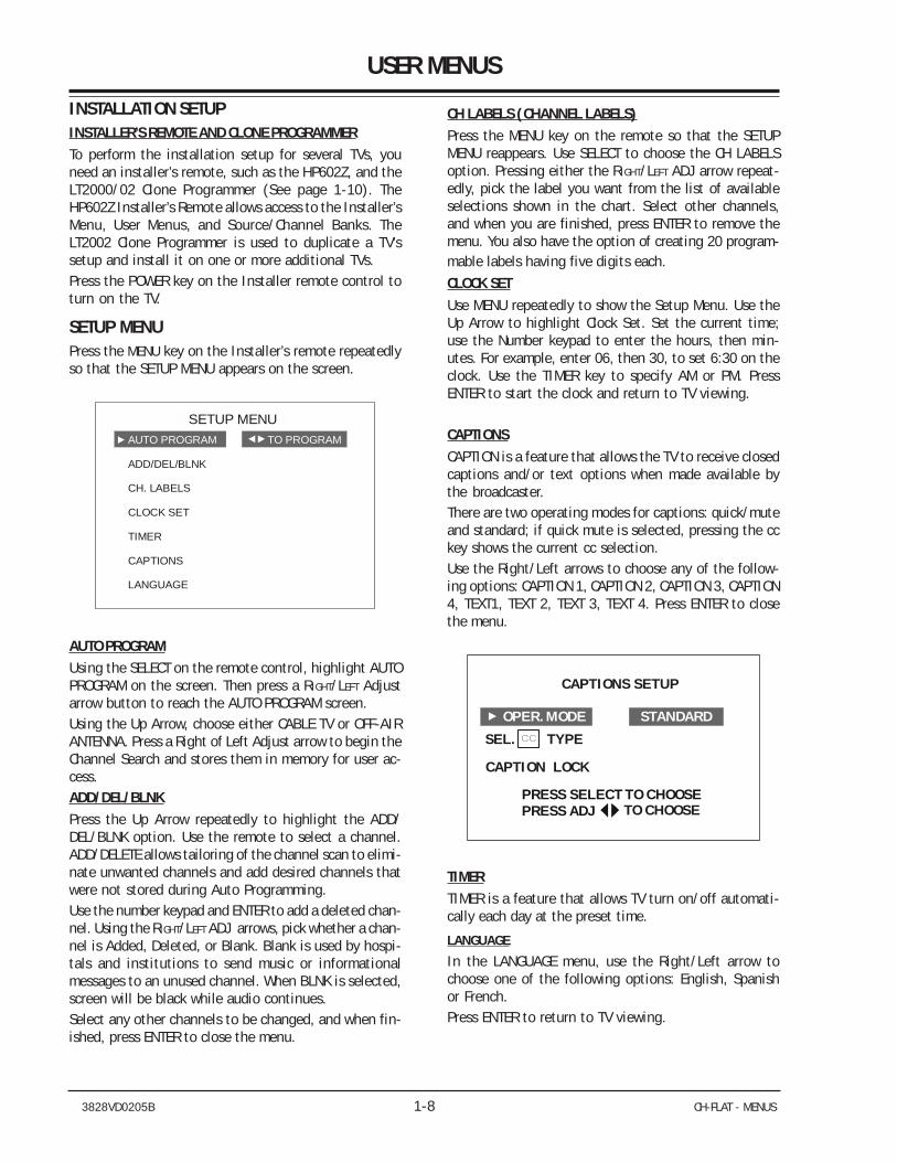
INSTALLATION SETUPINSTALLER’S REMOTE AND CLONE PROGRAMMERTo perform the installation setup for several TVs, youneed an installer’s remote, such as the HP602Z, and theLT2000/02 Clone Programmer (See page 1-10). TheHP602Z Installer’s Remote allows access to the Installer’sMenu, User Menus, and Source/Channel Banks. TheLT2002 Clone Programmer is used to duplicate a TV’ssetup and install it on one or more additional TVs.Press the POWER key on the Installer remote control toturn on the TV.
SETUP MENUPress the MENU key on the Installer’s remote repeatedlyso that the SETUP MENU appears on the screen.
ADD/DEL/BLNK
LOCK SET
TIMER
CAPTIONS
LANGUAGE
CH. LABELS
C
SETUP MENUAUTO PROGRAM TO PROGRAM
AUTO PROGRAMUsing the SELECT on the remote control, highlight AUTOPROGRAM on the screen. Then press a RIGHT/LEFT Adjustarrow button to reach the AUTO PROGRAM screen.Using the Up Arrow, choose either CABLE TV or OFF-AIRANTENNA. Press a Right of Left Adjust arrow to begin theChannel Search and stores them in memory for user ac-cess.ADD/DEL/BLNKPress the Up Arrow repeatedly to highlight the ADD/DEL/BLNK option. Use the remote to select a channel.ADD/DELETE allows tailoring of the channel scan to elimi-nate unwanted channels and add desired channels thatwere not stored during Auto Programming.Use the number keypad and ENTER to add a deleted chan-nel. Using the RIGHT/LEFT ADJ arrows, pick whether a chan-nel is Added, Deleted, or Blank. Blank is used by hospi-tals and institutions to send music or informationalmessages to an unused channel. When BLNK is selected,screen will be black while audio continues.Select any other channels to be changed, and when fin-ished, press ENTER to close the menu.
CH LABELS (CHANNEL LABELS)Press the MENU key on the remote so that the SETUPMENU reappears. Use SELECT to choose the CH LABELSoption. Pressing either the RIGHT/LEFT ADJ arrow repeat-edly, pick the label you want from the list of availableselections shown in the chart. Select other channels,and when you are finished, press ENTER to remove themenu. You also have the option of creating 20 program-mable labels having five digits each.
CLOCK SETUse MENU repeatedly to show the Setup Menu. Use theUp Arrow to highlight Clock Set. Set the current time;use the Number keypad to enter the hours, then min-utes. For example, enter 06, then 30, to set 6:30 on theclock. Use the TIMER key to specify AM or PM. PressENTER to start the clock and return to TV viewing.
CAPTIONSCAPTION is a feature that allows the TV to receive closedcaptions and/or text options when made available bythe broadcaster.There are two operating modes for captions: quick/muteand standard; if quick mute is selected, pressing the cckey shows the current cc selection.Use the Right/Left arrows to choose any of the follow-ing options: CAPTION 1, CAPTION 2, CAPTION 3, CAPTION4, TEXT1, TEXT 2, TEXT 3, TEXT 4. Press ENTER to closethe menu.
CAPTIONS SETUP
SEL. TYPE
CAPTION LOCK
PRESS SELECT TO CHOOSEPRESS ADJ TO CHOOSE
STANDARDOPER. MODE
TIMERTIMER is a feature that allows TV turn on/off automati-cally each day at the preset time.
LANGUAGE
In the LANGUAGE menu, use the Right/Left arrow tochoose one of the following options: English, Spanishor French.Press ENTER to return to TV viewing.
3828VD0205B 1-9 CH-FLAT - MENUS
USER MENUS (continued)
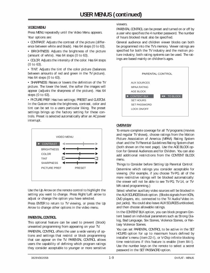
VIDEO MENUPress MENU repeatedly until the Video Menu appears.Your options are:• CONTRAST: Adjusts the contrast of the picture (differ-ence between white and black). Has 64 steps (0 to 63).• BRIGHTNESS: Adjusts the brightness of the picture(amount of white). Has 64 steps (0 to 63).• COLOR: Adjusts the intensity of the color. Has 64 steps(0 to 63).• TINT: Adjusts the tint of the color picture (balancesbetween amounts of red and green in the TV picture).Has 64 steps (0 to 63).• SHARPNESS: Raises or lowers the definition of the TVpicture. The lower the level, the softer the images willappear (adjusts the sharpness of the picture). Has 64steps (0 to 63).• PICTURE PREF: Has two settings; PRESET and CUSTOM.In the Custom mode the brightness, contrast, color andtint can be set to a users particular liking. The presetsettings brings up the factory setting for these con-trols. Preset is selected automatically after an AC powerinterrupt.
BRIGHTNESS
COLOR
TINT
VIDEO MENU
CONTRAST
PICTURE PREF PRESET
SHARPNESS
Use the Up Arrow on the remote control to highlight thesetting you want to change. Press Right/Left arrow toadjust or change the option you have selected.Press ENTER to return to TV viewing, or press the UpArrow to change other options in the video menu.
PARENTAL CONTROLThis optional feature can be used to prevent (block)unwanted programming from appearing on your TV.PARENTAL CONTROL offers the user a wide variety of op-tions and settings that restrict or block programmingthat can appear on the TV. PARENTAL CONTROL allowsusers the capability of defining which program ratingsthey consider acceptable to younger or more sensitive
viewers.PARENTAL CONTROL can be preset and turned on or off bya user who specifies the 4 number password. The numberof hours blocked must also be specified.General audience and children viewer blocks can bothbe programmed into the TV’s memory. Viewer ratings arespecified for both the TV industry and the motion pic-ture industry; both rating systems can be used. The rat-ings are based mainly on children’s ages.
AUX SOURCES
MPAA RATING
AGE BLOCK
CONTENT BLK SET HOURS SET PASSWORD
LOCK ON/OFF
TO BLOCK
OVERVIEWTo ensure complete coverage for all TV programs (moviesand regular TV shows), choose ratings from the MotionPicture Association of America (MPAA) Rating Systemchart and the TV Parental Guidelines Rating System chart(both shown on the next page). Use the AGE BLOCK op-tion for General Audiences and for Children. You can alsoadd additional restrictions from the CONTENT BLOCKmenu.Things to Consider before Setting Up Parental Control:Determine which ratings you consider acceptable forviewing. (For example, if you choose TV-PG, all of themore restrictive ratings will be blocked automatically:the viewer will not be able to see TV-PG, TV-14, or TV-MA rated programming.)Select whether auxiliary video sources will be blocked inthe AUX SOURCES block option. (Blocks signals from VCRs,DVD players, etc. connected to the TV Audio/Video in-put jacks). You could also leave AUX SOURCES unblocked,and then choose allowable ratings.In the CONTENT BLK option, you can block program Con-tent based on individual parameters such as Strong Dia-log, Bad Language, Sex Scenes, Violence Scenes, or Fan-tasy Violence Scenes.You can set PARENTAL CONTROL to be active in the SETHOURS option for up to maximum hours defined byinstaller´s menu (item 22-I), or V-Chip infinite blockingtime restrictions if this feature is enable (item 84-I).Use the number keys on the remote to select a secretpassword in the SET PASSWORD option.
3828VD0205B 1-10 CH-FLAT - MENUS
USER MENUS (continued)
ON-SCREEN DISPLAYSCHANNEL/TIMEPress ENTER. Shows currently selected channel or source,and current time if the clock has been set.
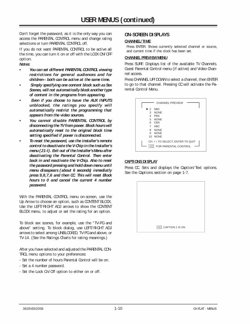
CHANNEL PREVIEW MENUPress SURF. Displays list of the available TV Channels.Guest Parental Control menu (if active) and Video Chan-nel access.Press CHANNEL UP/DOWN to select a channel, then ENTERto go to that channel. Pressing CC will activate the Pa-rental Control Menu.
CHANNEL PREVIEW
CH TO SELECT, ENTER TO QUIT
10 9 8 7 6 5 4 3 2
CC FOR PARENTAL CONTROL
NONEPBS
CBS
NBC
NONENONE
NONE
ABC
NONE
2 2
NBCNBC
CAPTIONS DISPLAYPress CC. Sets and displays the Caption/Text options.See the Captions section on page 1-7.
CC CAPTION 1 IS ON
Don’t forget the password, as it is the only way you canaccess the PARENTAL CONTROL menu and change ratingselections or turn PARENTAL CONTROL off.If you do not want PARENTAL CONTROL to be active allthe time, you can turn it on or off with the LOCK ON/OFFoption.Notes:• You can set different PARENTAL CONTROL viewing
restrictions for general audiences and forchildren-- both can be active at the same time.
• Simply specifying one content block such as SexScenes, will not automatically block another typeof content in the programs from appearing.
• Even if you choose to leave the AUX INPUTSunblocked, the ratings you specify willautomatically restrict the programming thatappears from the video sources.
• You cannot disable PARENTAL CONTROL bydisconnecting the TV from power. Block hours willautomatically reset to the original block timesetting specified if power is disconnected.
• To reset the password, use the installer’s remotecontrol to deactivate the V-Chip in the Installer’smenu (21-I). Exit out of the Installer’s Menu afterdeactivating the Parental Control. Then enterback in and reactivate the V-Chip. Also to resetthe password pressing and hold down menu untilmenu dissapears (about 6 seconds) inmediatlypress 9,8,7,6 and then CC. This will reset Blockhours to 0 and cancel the current 4 numberpassword.
With the PARENTAL CONTROL menu on-screen, use theUp Arrow to choose an option, such as CONTENT BLOCK.Use the LEFT/RIGHT ADJ arrows to show the CONTENTBLOCK menu, to adjust or set the rating for an option.
To block sex scenes, for example, use the “TV-PG andabove” setting. To block dialog, use LEFT/RIGHT ADJarrows to select among UNBLOCKED, TV-PG and above, orTV-14. (See the Ratings Charts for rating meanings.)
After you have selected and adjusted the PARENTAL CON-TROL menu options to your preferences:- Set the number of hours Parental Control will be on.- Set a 4 number password.- Set the Lock On/Off option to either on or off.
3828VD0205B 1-11 CH-FLAT - MENUS
USER MENUS (continued)
RADIO FEATUREPressing the TV/FM key allows the customer to listen theRadio. The Auto Program feature automatically searchesfor all available Radio Stations and marks them as ‘added’so that they may be accessed via the channel Up/Downkey.
In the Auto Program screen:
A message at the top displays “Auto Program” to letthe customer know that they have entered the AutoProgram feature.
To start the Auto Program, press the Left/Right Arrowkey.
Note: While searching for radio stations, all keys aredisabled. This prevents an incomplete AutoProgram procedure. Running the Auto Programwill clear the factory mode, if it was active. Thishappens at the end of the Auto Program. If noradio stations are found, then the followingmessage will appear: “Make sure that the antennais connected, and try again”.
FM ADD/DELAllows tailoring of the station scan results to eliminateweak and unwanted stations. Use FM ADD/DELETE to getrid of unwanted stations or to program back in a previ-ously deleted station.
Note: After using the FM Add/Del function, returnto TV mode (press TV/FM key) before turningthe TV off. This ensures that the FM Add/Delchanges are saved in memory.
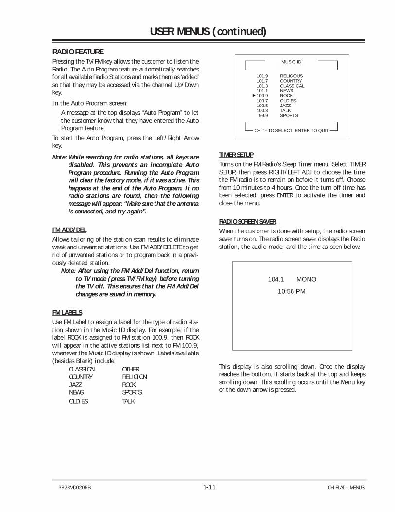
FM LABELSUse FM Label to assign a label for the type of radio sta-tion shown in the Music ID display. For example, if thelabel ROCK is assigned to FM station 100.9, then ROCKwill appear in the active stations list next to FM 100.9,whenever the Music ID display is shown. Labels available(besides Blank) include:
CLASSICAL OTHERCOUNTRY RELIGIONJAZZ ROCKNEWS SPORTSOLDIES TALK
101.9 RELIGOUS101.7 COUNTRY101.3 CLASSICAL101.1 NEWS100.9 ROCK100.7 OLDIES100.5 JAZZ100.3 TALK 99.9 SPORTS
MUSIC ID
CH TO SELECT ENTER TO QUIT
TIMER SETUPTurns on the FM Radio’s Sleep Timer menu. Select TIMERSETUP, then press RIGHT/LEFT ADJ to choose the timethe FM radio is to remain on before it turns off. Choosefrom 10 minutes to 4 hours. Once the turn off time hasbeen selected, press ENTER to activate the timer andclose the menu.
RADIO SCREEN SAVERWhen the customer is done with setup, the radio screensaver turns on. The radio screen saver displays the Radiostation, the audio mode, and the time as seen below.
104.1 MONO
10:56 PM
This display is also scrolling down. Once the displayreaches the bottom, it starts back at the top and keepsscrolling down. This scrolling occurs until the Menu keyor the down arrow is pressed.
3828VD0205B 1-12 CH-FLAT - MENUS
USER MENUS (continued)
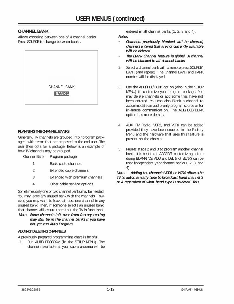
CHANNEL BANKAllows choosing between one of 4 channel banks.Press SOURCE to change between banks.
BANK 1
PLANNING THE CHANNEL BANKSGenerally, TV channels are grouped into “program pack-ages” with terms that are proposed to the end user. Theuser then opts for a package. Below is an example ofhow TV channels may be grouped.
Channel Bank Program package
1 Basic cable channels
2 Extended cable channels
3 Extended with premium channels
4 Other cable service options
Sometimes only one or two channel banks may be needed.You may leave any unused bank with the channels. How-ever, you may want to leave at least one channel in anyunused bank. Then, if someone selects an unused bank,that channel will assure them that the TV is functional.Note: Some channels left over from factory testing
may still be in the channel banks if you havenot yet run Auto Program.
ADDING/DELETING CHANNELSA previously prepared programming chart is helpful.1. Run AUTO PROGRAM (in the SETUP MENU). The
channels available at your cable/antenna will be
entered in all channel banks (1, 2, 3 and 4).Notes:• Channels previously blanked will be cleared;
channels entered that are not currently availablewill be deleted.
• The Blank Channel feature is global. A channelwill be blanked in all channel banks.
2. Select a channel bank with a remote press SOURCE/BANK (and repeat). The Channel BANK and BANKnumber will be displayed.
3. Use the ADD/DEL/BLNK option (also in the SETUPMENU) to customize your program package. Youmay delete channels or add some that have notbeen entered. You can also Blank a channel toaccommodate an audio-only program source or forin-house communication. The ADD/DEL/BLNKoption has more details.
4. AUX, FM Radio, VCR3, and VCR4 can be addedprovided they have been enabled in the FactoryMenu and the hardware that uses this feature ispresent on the chassis.
5. Repeat steps 2 and 3 to program another channelbank. It is best to do ADD/DEL customizing beforedoing BLANKING. ADD and DEL (not BLNK) can beused independently for channel banks 1, 2, 3, and4).
Note: Adding the channels VCR3 or VCR4 allows theTV to automatically tune to broadcast band channel 3or 4 regardless of what band type is selected. This
3828VD0205B 2-1 CH-FLAT - FACTORY MENU
FACTORY MENU
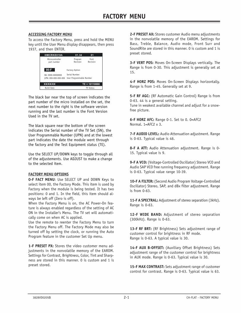
ACCESSING FACTORY MENUTo access the Factory Menu, press and hold the MENUkey until the User Menu display disappears, then press1937, and then ENTER.
0IMCRKE018A 01.34 01
XX/XX/XX TE = 10110000
00-F
Microcontrollerpart number
ProgramRevision
FontRevision
SN: XXXX-XXXXXXXX UPN: XXX-XXX-XXX-XXX
Build Date TE Status
Factory Option
Serial Number
User Programmable Number
The black bar near the top of screen indicates thepart number of the micro installed on the set, thenext number to the right is the software versionrunning and the last number is the Font VersionUsed in the TV set.
The black square near the bottom of the screenindicates the Serial number of the TV Set (SN), theUser Programmable Number (UPN) and at the lowestpart indicates the date the module went throughthe factory and the Test Equipment status (TE).
Use the SELECT UP/DOWN keys to toggle through allof the adjustements. Use ADJUST to make a changeto the selected item.
FACTORY MENU OPTIONS0-F FACT MENU: Use SELECT UP and DOWN Keys toselect item 00, the Factory Mode. This item is used byFactory when the module is being tested. It has twopositions: 0 and 1. In the field, this item should al-ways be left off (Zero is off).When the Factory Menu is on, the AC Power-On fea-ture is always enabled regardless of the setting of ACON in the Installer’s Menu. The TV set will automati-cally come on when AC is applied.Use the remote to reenter the Factory Menu to turnthe Factory Menu off. The Factory Mode may also beturned off by setting the clock, or running the AutoProgram feature in the customer Set Up menu.
1-F PRESET PX: Stores the video customer menu ad-justments in the nonvolatile memory of the EAROM.Settings for Contrast, Brightness, Color, Tint and Sharp-ness are stored in this manner. 0 is custom and 1 ispreset stored.
2-F PRESET AX: Stores customer Audio menu adjustmentsin the nonvolatile memory of the EAROM. Settings forBass, Treble, Balance, Audio mode, Front Surr andSoundRite are stored in this manner. 0 is custom and 1 ispreset stored.
3-F VERT P0S: Moves On-Screen Displays vertically. TheRange is from 0-30. This adjustment is generally set at15.
4-F H0RZ POS: Moves On-Screen Displays horizontally.Range is from 1-45. Generally set at 9.
5-F RF AGC: (RF Automatic Gain Control) Range is from0-63. 44 is a general setting.Tune in weakest available channel and adjust for a snow-free picture.
6-F HORZ AFC: Range 0-1. Set to 0. 0=AFC2Normal. 1=AFC2 x 3.
7-F AUDIO LEVEL: Audio Attenuation adjustment. Rangeis 0-63. Typical value is 46.
8-F A ATT: Audio Attenuation adjustment. Range is 0-15. Typical value is 9.
9-F A VCO: (Voltage-Controlled Oscillator) Stereo VCO andAudio SAP VCO free running frequency adjustment. Rangeis 0-63. Typical value range 10-39.
10-F A FILTER: (Second Audio Program Voltage-ControlledOscillator) Stereo, SAP, and dBx filter adjustment. Rangeis from 0-63.
11-F A SPECTRAL: Adjustment of stereo separation (3kHz).Range is 0-63.
12-F WIDE BAND: Adjustment of stereo separation(300kHz). Range is 0-63.
13-F RF BRT: (RF Brightness) Sets adjustment range ofcustomer control for brightness in RF mode.Range is 0-63. A typical value is 30.
14-F AUX B-OFFSET: (Auxiliary Offset Brightness) Setsadjustment range of the customer control for brightnessin AUX mode. Range is 0-63. Typical value is 30.
15-F MAX CONTRAST: Sets adjustment range of customercontrol for contrast. Range is 0-63. Typical value is 63.
3828VD0205B 2-2 CH-FLAT - FACTORY MENU
FACTORY MENU(continued)
16-F WHITE COMP: (White Compression) Rage o-1. 0=Enable and 1=Disable
17-F TRAP 3.58: Zero is off and one is on. Set to 1 fornormal TV operation. Set to 0 if Y/C is used or chassishas a comb filter.
18-F 60HZ SW: (60 Hertz Switched) The range is 0 to 2.
19-F PIF VCO: (PIF Voltage Controlled Oscillator) Rangeis 0 to 127.
20-F RF BAND PASS: Sets adjustment range of the cus-tomer control for brightness in therefore mode. Range is0-1. Set to 1.
21-F RED CUT: B&W tracking adjustment. Range is 0-254. Typical value is 70.
22-F GREEN CUT: B&W tracking adjustment. Range is 0-254. Typical value is 70.
23-F BLUE CUT: B&W tracking adjustment. Range is 0-254. Typical value is 70.
24-F GREEN GAIN: B&W tracking adjustment. Range is 0-254. Typical value is 45.
25-F BLUE GAIN: B&W tracking adjustment. Range is 0-254. Typical value is 70.
26-F VERT SIZE: (Vertical Size) Range is 0-254.
27-F HORZ SIZE: (Horizontal Size) This register does nothave any effect.
28-F VERT PHASE: (Vertical Phase) Range is 0-7.
29-F HORZ PHASE: (Horizontal Phase)Range is from 0-31.
30-F AIR AFT: Force to AFC in Air Band.Range is 0/1. Typical value is 0.
31-F EN LA7222: This register does not have any effect.
32-F CUT OFF RESET:
33-F GAW RESET:
34-F RF WHITE ADJ:
35-F BLACK ADJ:
3828VD0205B 2-3 CH-FLAT - INSTALLER’S MENU
INSTALLER’S MENU
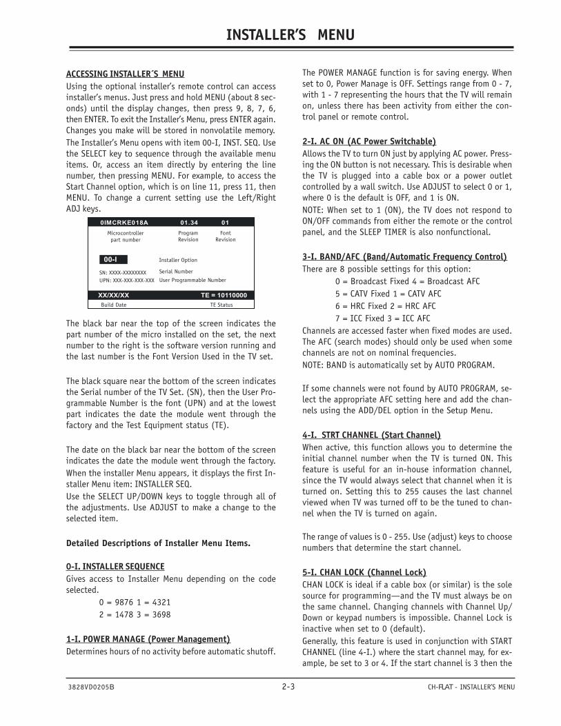
ACCESSING INSTALLER´S MENUUsing the optional installer’s remote control can accessinstaller’s menus. Just press and hold MENU (about 8 sec-onds) until the display changes, then press 9, 8, 7, 6,then ENTER. To exit the Installer’s Menu, press ENTER again.Changes you make will be stored in nonvolatile memory.The Installer’s Menu opens with item 00-I, INST. SEQ. Usethe SELECT key to sequence through the available menuitems. Or, access an item directly by entering the linenumber, then pressing MENU. For example, to access theStart Channel option, which is on line 11, press 11, thenMENU. To change a current setting use the Left/RightADJ keys.
0IMCRKE018A 01.34 01
XX/XX/XX TE = 10110000
00-I
Microcontrollerpart number
ProgramRevision
FontRevision
SN: XXXX-XXXXXXXX UPN: XXX-XXX-XXX-XXX
Build Date TE Status
Installer Option
Serial Number
User Programmable Number
The black bar near the top of the screen indicates thepart number of the micro installed on the set, the nextnumber to the right is the software version running andthe last number is the Font Version Used in the TV set.
The black square near the bottom of the screen indicatesthe Serial number of the TV Set. (SN), then the User Pro-grammable Number is the font (UPN) and at the lowestpart indicates the date the module went through thefactory and the Test Equipment status (TE).
The date on the black bar near the bottom of the screenindicates the date the module went through the factory.When the installer Menu appears, it displays the first In-staller Menu item: INSTALLER SEQ.Use the SELECT UP/DOWN keys to toggle through all ofthe adjustments. Use ADJUST to make a change to theselected item.
Detailed Descriptions of Installer Menu Items.
0-I. INSTALLER SEQUENCEGives access to Installer Menu depending on the codeselected.
0 = 9876 1 = 43212 = 1478 3 = 3698
1-I. POWER MANAGE (Power Management)Determines hours of no activity before automatic shutoff.
SECTION 2
The POWER MANAGE function is for saving energy. Whenset to 0, Power Manage is OFF. Settings range from 0 - 7,with 1 - 7 representing the hours that the TV will remainon, unless there has been activity from either the con-trol panel or remote control.
2-I. AC ON (AC Power Switchable)Allows the TV to turn ON just by applying AC power. Press-ing the ON button is not necessary. This is desirable whenthe TV is plugged into a cable box or a power outletcontrolled by a wall switch. Use ADJUST to select 0 or 1,where 0 is the default is OFF, and 1 is ON.NOTE: When set to 1 (ON), the TV does not respond toON/OFF commands from either the remote or the controlpanel, and the SLEEP TIMER is also nonfunctional.
3-I. BAND/AFC (Band/Automatic Frequency Control)There are 8 possible settings for this option:
0 = Broadcast Fixed 4 = Broadcast AFC5 = CATV Fixed 1 = CATV AFC6 = HRC Fixed 2 = HRC AFC7 = ICC Fixed 3 = ICC AFC
Channels are accessed faster when fixed modes are used.The AFC (search modes) should only be used when somechannels are not on nominal frequencies.NOTE: BAND is automatically set by AUTO PROGRAM.
If some channels were not found by AUTO PROGRAM, se-lect the appropriate AFC setting here and add the chan-nels using the ADD/DEL option in the Setup Menu.
4-I. STRT CHANNEL (Start Channel)When active, this function allows you to determine theinitial channel number when the TV is turned ON. Thisfeature is useful for an in-house information channel,since the TV would always select that channel when it isturned on. Setting this to 255 causes the last channelviewed when TV was turned off to be the tuned to chan-nel when the TV is turned on again.
The range of values is 0 - 255. Use (adjust) keys to choosenumbers that determine the start channel.
5-I. CHAN LOCK (Channel Lock)CHAN LOCK is ideal if a cable box (or similar) is the solesource for programming—and the TV must always be onthe same channel. Changing channels with Channel Up/Down or keypad numbers is impossible. Channel Lock isinactive when set to 0 (default).Generally, this feature is used in conjunction with STARTCHANNEL (line 4-I.) where the start channel may, for ex-ample, be set to 3 or 4. If the start channel is 3 then the
3828VD0205B 2-4 CH-FLAT - INSTALLER’S MENU
INSTALLER’S MENU (continued)
TV will remain on channel 3. NOTE: When CHANNEL LOCKis active and CHANNEL OVERIDE is disabled, AUTO PRO-GRAM is not active.
6-I. GHOST CH (Ghost Channel)When set to 1, the current channel number is displayedin the upper right corner of the CRT. The number movesslightly to prevent damage to the screen. The default is“0” or OFF. NOTE: When captions are on, the “ghost chan-nel” is not displayed.
7-I. START VOLUMEThis function allows the Installer to determine the initialvolume level setting when the TV is turned ON. This fea-ture is useful for an in-house information channel, sincethe TV would always select that volume level when it isturned on. The range of values are 0 - 63, 255. If 255 isselected, the current volume level will be retained inmemory when the TV is turned off; at TV turn on, volumelevel is automatically set to the previous or last level.
8-I. MIN VOLUME (Minimum Volume)This function determines the minimum volume level al-lowable with the VOLUME (VOL) Up/Down control. In thisway, for example, someone cannot set the volume toolow to hear. The range is from 0 to 63—change valueswith ADJUST. The factory default is 0, which provides fullrange of volume control. It may be best to set the samevalue on every TV.NOTE: The minimum volume level cannot have a valuesetting higher than in the MAX VOLUME level (describedbelow).
9-I. MAX VOLUME (Maximum Volume)This function determines the maximum volume level al-lowable with the VOLUME VOL Up/Down control. In thisway, for example, someone cannot set the volume levelhigh enough to disturb others. The range is 0 to 63,with 63 as the default which gives the user the full rangeof volume control. Change values with ADJUST keys. Itmay be best to set the same value on every TV. NOTE: Themaximum volume level cannot have a value setting lowerthan the MIN VOLUME level (described previously).
10-I. MUTE DISABLEEnables or disables sound mute function. When set to 1,sound cannot be muted. When set to 0, sound can bemuted.
11 KEY DEFEAT (Keyboard Defeat)When set to 1, it prevents the end user from accessingscreen menus on the front panel—MENU, SELECT, and AD-JUST do not function. When set to 0, those keys are
functional. The menus can always be accessed with MENUon the remote.
12-I. IR BANKS EN.For direct access to a particular Channel Bank. When en-abled, installer can access a channel bank by inputtingthe IR code for the bank.
13-I. SCAN MODEAllows variation in setting the On/Off with Channel UP/DOWN. You may opt for TV channels only; TV channels +Off/ON; TV channels + FM radio; TV channels + FM radio +Off/On with these settings for Scan Mode:Scan mode Characteristics
0 Channel up/down keys change channels only.1 Channel down below the lowest channel
(orchannel up higher than the highest) and TV turns off.
2 Channel down below the lowest channel (or up higher than the highest) and TV goes to FM radio. Channel down below lowest FM sta tion (or Channel up higher than the highest)
and TV channels return.3 Channel down below the lowest channel (or
up higher than the highest) and TV goes to FM radio. Press channel down below lowest FM station (or Channel up higher than the highest) and TV turns off.
14-I. STRT CH IN SMWhen set to 1, installs TV on/off event below the startchannel at TV turn on.
15-I. SLEEP TIMERWhen set to 1, the SLEEP TIMER feature may be used (butno message is displayed prior to turn-off). When set to0, the sleep timer is not available.
16-I. EN. TIMERSet to 1, timer function is available to user. Set to 0 todisable timer functions. (Clock must be set in order touse Timers.)
17-I. ALARMGives you the option of making the alarm function avail-able to the user. Set to 1, alarm function is available touser. Set to 0 to disable the Alarm function.Note: Clock must be set in order to set the Alarm.
18-I. RADIOSet to 1, for TVs with a Radio. Set to 0 to disable theRadio function, for TVs without a Radio.
3828VD0205B 2-5 CH-FLAT - INSTALLER’S MENU
INSTALLER’S MENU (continued)
19-I. NOT USED
20-I. FEATURE LEVELDefault set to ZEN 1 for Zenith IR remote control opera-tion. Set O, P LBL for Zenith Private Label IR remotecontrol operation. Warning: Do not set to “0” or remotewill not control TV.Installer should leave item 20 FEATURELEVEL, set to 1 (default).
Installer should leave item 20 FEATURE LEVELset to 1 (default).
21-I. V-CHIPSet to 1 to activate V-Chip (Parental Control); have itavailable to user to filter, control, or restrict program-ming content. Set to 0 to turn V-Chip feature off, notavailable to user; no programming restrictions can beset.
22-I. MAX BLK HRSSet to 0 to 99 for the maximum V-Chip (Parental Control)block hours. Default is 12 blocking hours.
23-I. CAPTION LOCKSet to 1 to restore previous caption On/Off state after TVturns off. When set to 0, captions are always off, whenTV is initially turned on.
24-I. TEXT MODEDetermines whether TEXT 1, TEXT 2, TEXT 3, or TEXT 4decoding is enabled when TEXT is turned on (either fromthe Setup Menu or directly with CC on the remote).TIP: Set Text Mode to 1 only if text is offered in yourvideo system.
25-I. FUNCTION PRE.Set to 0 to suppress CHANNEL PREVIEW from the FUNC-TION menu with some Pay-Per-View systems.
26-I. 6 KEY SYSSet to 1 for 6-key front control panels. Set to 0 for 10-key front control panels. Leave default set to 1.
27-I. HOSPITAL MODEThe default is 2 (which favors most hospitals). With thissetting two things are affected: Channel Banks 1, 2, and3 are accessible, while Bank 4 is inactive.
28-I. CH. OVERRIDE (Channel Override)When set to 1, the user can select channels with eitherChannel Up/Down or by direct keypad entry. When set to0, only those channels that are entered for scanning maybe selected by direct keypad entry. Note: If set to 0,Auto Program is locked; (as shown on Setup menu) chan-nel search is not possible.
29-I. OLD OCV (On Command VideoTM)Set to 1 for operation with systems from On CommandCorporation.
30-I. ACK MASKM.P.I. Communication Parameter. Leave at default set-ting unless changed by Pay-Per-View provider.
31-I. POLL RATEM.P.I. Communication Parameter. Leave at default set-ting unless changed by Pay-Per-View provider.
32-I. TIMING PULSEM.P.I. Communication Parameter. Leave at default set-ting unless changed by Pay-Per-View provider.
33-I. NOT USED
34-I. NOT USED
35-I. NOT USED
36-I. NOT USED
37-I. NOT USED
38-I. NOT USED
39-I. REAR VIDEO EN.Set to 1 to enable rear AUX (Video) input.Set to 0 to disable rear AUX input.
40-I. NOT USED
41-I. NOT USED
42-I. NOT USED
43-I. NOT USED
44-I. NOT USED
3828VD0205B 2-6 CH-FLAT - INSTALLER’S MENU
INSTALLER’S MENU (continued)
45-I. NOT USED
46-I. NOT USED
47-I. NOT USED
48-I. DIS. SETUP M.Set to 1 to disable the Setup menu. Setup menu will noappear. Set to 0 to enable the Setup menu.
49-I. NOT USED
50-I. DIS. VIDEO M.Set to 1 to disable the Video menu. Video menu will notappear. Set to 0 to enable the Video menu.
51-I. DIS. VCHIP M.Set to 1 to disable the Parental Control menu. ParentalControl menu will not appear.Set to 0 to enable the Parental Control menu.
52-I. NOT USED
53-I. DIS. CH-TIME.Set to 1 to disable the Channel-Time display. Channel-Time display will not appear.Set to 0 to enable the Channel-Time display.
54-I. EN. SET. COL.Set to 1 to enable custom color settings for the Setupmenu. Set to 0 to disable custom color settings for theSetup menu
55-I. FOR. SETUP M.(Setup Menu Foreground Color)Set according to Color Chart.0 = Black 3 = Yellow 6 = Cyan1 = Red 4 = Blue 7 = White2 = Green 5 = Violet
56-I. BCK. SETUP M.(Setup Menu Background Color)Set according to Color Chart.0 = Black 3 = Yellow 6 = Cyan1 = Red 4 = Blue 7 = White2 = Green 5 = Violet
57-I. NOT USED
58-I. NOT USED
59-I. NOT USED
60-I. EN. VIDEO. COL.Set to 1 to enable custom color settings for the Videomenu. Set to 0 to disable custom color settings for theVideo menu.
61-I. FOR. VIDEO M.(Video Menu Foreground Color)Set according to Color Chart.0 = Black 3 = Yellow 6 = Cyan1 = Red 4 = Blue 7 = White2 = Green 5 = Violet
62-I. BCK. VIDEO. COL.(Video Menu Background Color)Set according to Color Chart.0 = Black 3 = Yellow 6 = Cyan1 = Red 4 = Blue 7 = White2 = Green 5 = Violet
63-I. EN. PTL. COL.Set to 1 to enable custom color settings for the V-Chipmenu. Set to 0 to disable custom color settings for theV-Chip menu.
64-I. FOR. PTL. M.(V-Chip Menu Foreground Color)Set according to Color Chart.0 = Black 3 = Yellow 6 = Cyan1 = Red 4 = Blue 7 = White2 = Green 5 = Violet
65-I. BCK. PTL. M.(V-Chip Menu Background Color)Set according to Color Chart.0 = Black 3 = Yellow 6 = Cyan1 = Red 4 = Blue 7 = White2 = Green 5 = Violet
66-I. NOT USED
67-I. NOT USED
68-I. NOT USED
69-I. EN. CH-T COL.Set to 1 to enable custom color for the Channel-Timedisplay. Set to 0 to disable custom color for the Channel-Time display.
3828VD0205B 2-7 CH-FLAT - INSTALLER’S MENU
INSTALLER’S MENU (continued)
70-I. FOR. CH-T COL.(Channel-Time Display Foreground Color)Set according to Color Chart.0 = Black 3 = Yellow 6 = Cyan1 = Red 4 = Blue 7 = White2 = Green 5 = VioletNote: If foreground and background color are the same,menu background is transparent.
71-I. BCK. CH-T COL.(Channel-Time Display Background Color) Set accordingto Color Chart.
0 = Black 3 = Yellow 6 = Cyan1 = Red 4 = Blue 7 = White2 = Green 5 = Violet
Note: If foreground and background color are the same,menu background is transparent.
72-I. NOT USED
73-I. CH NOT AVBLEWhen set to 1 and channel override is set to 0, “NOTAVAILABLE” message is displayed when direct accessinga channel not in the favorite channel list.
74-I. CH-TIME SIZEWhen set to 1 and transparent background is selectedfor Channel-Time display, (foreground color = backgroundcolor and custom color enabled) a large channel numberis displayed instead of the normal Channel-Time display.
75-I. NOT USED
76-I. DEFEAT XDSSet to 1 to disable XDS display. Set to 0 to enable XDSdisplay.
77-I. QUICK SHUTOFFAllows TV power off to be controlled by the pillow speakerchannel selection button. User would press and hold but-ton down for time required to have TV turn off. ValueRange 0 - 17, each number represents 1/2 second. Forexample, if set to 4, TV would turn off if user held speakerchannel button down for 2 seconds.
78-I. UPN MSBUser programmable number, most significant byte read-able/writeable by M.P.I. command.
79-I. UPN MSB-1User programmable number, most significant byte-1 read-able/writeable by M.P.I. command.
80-I. UPN MSB-2User programmable number, most significant byte-2 read-able/writeable by M.P.I. command.
81-I. UPN LSBUser programmable number, least significant byte read-able/writeable by M.P.I. command.
82-I. CHKSM ERROREnforces rigid M.P.I checksum validation.Set to 1 for validation. Set to 0 to turn off.
83-I. HANDSHK TIMEAdds an additional delay to the handshake time which is64 msec, thus relaxing M.P.I. timing requirements to becompatible with PC based Windows controlled systems,range is 0 - 5. Set to 0 to retain standard 64 msec delay.Set to 1 - 5 to increase @ 16 msec additional, the delayup to 144 msec.
84-I. PERMANENT BLKAllows Parental Control blocking schemes to be perma-nent by removing the blocking hours function.Set to 1 to install Parental Control blocking restrictionspermanently. Set to 0 for user-specified hours control ofblocking schemes.
85-I. NOT USED
86-I. NOT USED
87-I. NOT USED
88-I. EN NOISE MUTEAllows to reduce the volume level automatically with noresignal or weak signal, set to 1 for future enable or todisable.
89-I. POKE ENABLEEnable/disable to write the memory (EAROM) by MPI thruthe command 17 data type 23 hex set to 1 for MPI pokeenable or 0 to disable.
90-I. KEY LOCKEnable/disable the front panel keyboard and pillow speaker.Set to 1 to disable and 0 for enable.
3828VD0205B 2-8 CH-FLAT - INSTALLER’S MENU
INSTALLER’S MENU (continued)
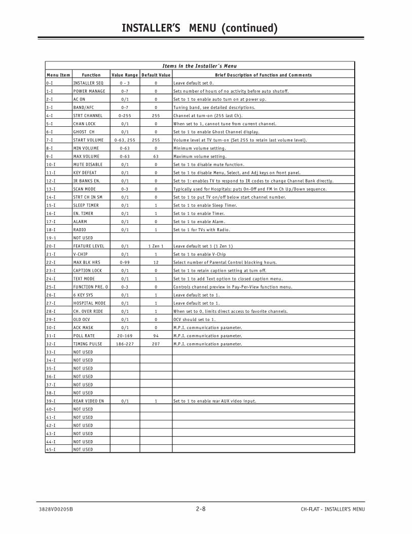
Menu Item Function Value Range Default Value Brief Description of Function and Comments
0-I INSTALLER SEQ 0 - 3 0 Leave defau lt set 0 .
1-I POWER MANAGE 0-7 0 Sets number of hours o f no activity befo re auto shutoff.
2-I AC ON 0/1 0 Set to 1 to enab le auto tu rn on at power up.
3-I BAND/AFC 0-7 0 Tuning band, see detailed descriptions.
4-I STRT CHANNEL 0-255 255 Channel at tu rn-on (255 last Ch).
5-I CHAN LOCK 0/1 0 When set to 1 , cannot tune from current channel.
6-I GHOST CH 0/1 0 Set to 1 to enab le Ghost Channel d isp lay.
7-I START VOLUME 0-63, 255 255 Volume level at TV tu rn-on (Set 255 to retain last vo lume level).
8-I MIN VOLUME 0-63 0 Minimum vo lume setting .
9-I MAX VOLUME 0-63 63 Maximum vo lume setting .
10-I MUTE DISABLE 0/1 0 Set to 1 to d isab le mute function.
11-I KEY DEFEAT 0/1 0 Set to 1 to d isab le Menu, Select, and Adj keys on front panel.
12-I IR BANKS EN. 0/1 0 Set to 1 : enables TV to respond to IR codes to change Channel Bank d irectly.
13-I SCAN MODE 0-3 0 Typ ically used fo r Hosp itals: puts On-Off and FM in Ch Up/Down sequence.
14-I STRT CH IN SM 0/1 0 Set to 1 to put TV on/off below start channel number.
15-I SLEEP TIMER 0/1 1 Set to 1 to enab le Sleep Timer.
16-I EN. TIMER 0/1 1 Set to 1 to enab le Timer.
17-I ALARM 0/1 0 Set to 1 to enab le Alarm.
18-I RADIO 0/1 1 Set to 1 fo r TVs with Rad io .
19-1 NOT USED
20-I FEATURE LEVEL 0/1 1 Zen 1 Leave defau lt set 1 (1 Zen 1)
21-I V-CHIP 0/1 1 Set to 1 to enab le V-Chip
22-I MAX BLK HRS 0-99 12 Select number o f Parental Contro l b locking hours.
23-I CAPTION LOCK 0/1 0 Set to 1 to retain caption setting at tu rn o ff.
24-I TEXT MODE 0/1 1 Set to 1 to add Text option to closed caption menu.
25-I FUNCTION PRE. O 0-3 0 Contro ls channel p review in Pay-Per-V iew function menu.
26-I 6 KEY SYS 0/1 1 Leave defau lt set to 1 .
27-I HOSPITAL MODE 0/1 1 Leave defau lt set to 1 .
28-I CH. OVER RIDE 0/1 1 When set to 0 , limits d irect access to favorite channels.
29-I OLD OCV 0/1 0 OCV shou ld set to 1 .
30-I ACK MASK 0/1 0 M.P.I. communication parameter.
31-I POLL RATE 20-169 94 M.P.I. communication parameter.
32-I TIMING PULSE 186-227 207 M.P.I. communication parameter.
33-I NOT USED
34-I NOT USED
35-I NOT USED
36-I NOT USED
37-I NOT USED
38-I NOT USED
39-I REAR VIDEO EN 0/1 1 Set to 1 to enab le rear AUX video input.
40-I NOT USED
41-I NOT USED
42-I NOT USED
43-I NOT USED
44-I NOT USED
45-I NOT USED
Items in the Installer´s Menu
3828VD0205B 2-9 CH-FLAT - INSTALLER’S MENU
INSTALLER’S MENU (continued)
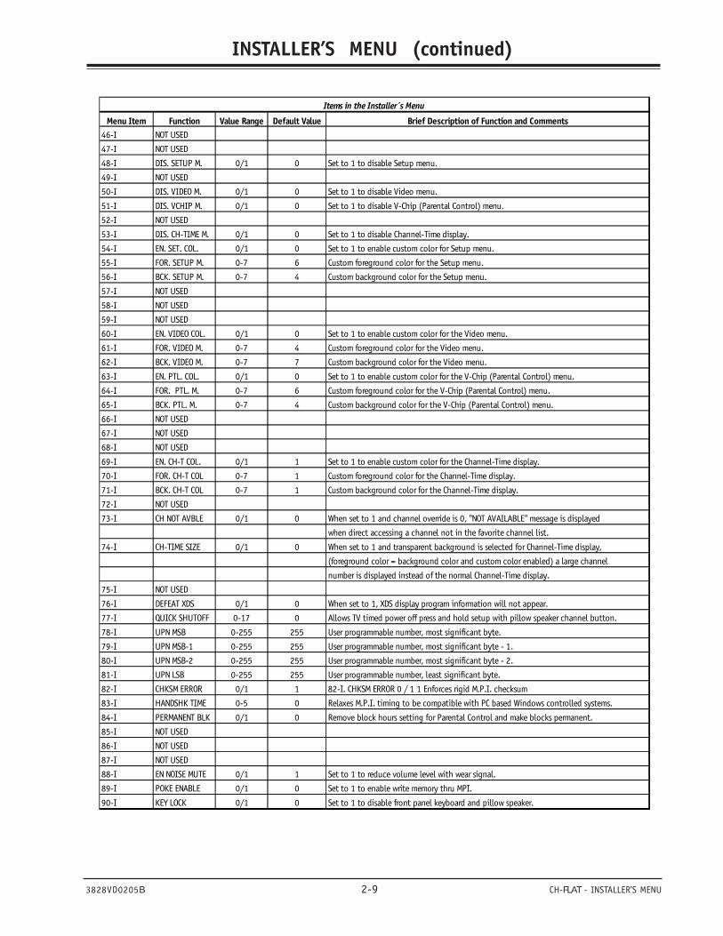
Menu Item Function Value Range Default Value Brief Description of Function and Comments46-I NOT USED
47-I NOT USED
48-I DIS. SETUP M. 0/1 0 Set to 1 to disable Setup menu.
49-I NOT USED
50-I DIS. VIDEO M. 0/1 0 Set to 1 to disable Video menu.
51-I DIS. VCHIP M. 0/1 0 Set to 1 to disable V-Chip (Parental Control) menu.
52-I NOT USED
53-I DIS. CH-TIME M. 0/1 0 Set to 1 to disable Channel-Time display.
54-I EN. SET. COL. 0/1 0 Set to 1 to enable custom color for Setup menu.
55-I FOR. SETUP M. 0-7 6 Custom foreground color for the Setup menu.
56-I BCK. SETUP M. 0-7 4 Custom background color for the Setup menu.
57-I NOT USED
58-I NOT USED
59-I NOT USED
60-I EN. VIDEO COL. 0/1 0 Set to 1 to enable custom color for the Video menu.
61-I FOR. VIDEO M. 0-7 4 Custom foreground color for the Video menu.
62-I BCK. VIDEO M. 0-7 7 Custom background color for the Video menu.
63-I EN. PTL. COL. 0/1 0 Set to 1 to enable custom color for the V-Chip (Parental Control) menu.
64-I FOR. PTL. M. 0-7 6 Custom foreground color for the V-Chip (Parental Control) menu.
65-I BCK. PTL. M. 0-7 4 Custom background color for the V-Chip (Parental Control) menu.
66-I NOT USED
67-I NOT USED
68-I NOT USED
69-I EN. CH-T COL. 0/1 1 Set to 1 to enable custom color for the Channel-Time display.
70-I FOR. CH-T COL 0-7 1 Custom foreground color for the Channel-Time display.
71-I BCK. CH-T COL 0-7 1 Custom background color for the Channel-Time display.
72-I NOT USED
73-I CH NOT AVBLE 0/1 0 When set to 1 and channel override is 0, "NOT AVAILABLE" message is displayed
when direct accessing a channel not in the favorite channel list.
74-I CH-TIME SIZE 0/1 0 When set to 1 and transparent background is selected for Channel-Time display,
(foreground color = background color and custom color enabled) a large channel
number is displayed instead of the normal Channel-Time display.
75-I NOT USED
76-I DEFEAT XDS 0/1 0 When set to 1, XDS display program information will not appear.
77-I QUICK SHUTOFF 0-17 0 Allows TV timed power off press and hold setup with pillow speaker channel button.
78-I UPN MSB 0-255 255 User programmable number, most significant byte.
79-I UPN MSB-1 0-255 255 User programmable number, most significant byte - 1.
80-I UPN MSB-2 0-255 255 User programmable number, most significant byte - 2.
81-I UPN LSB 0-255 255 User programmable number, least significant byte.
82-I CHKSM ERROR 0/1 1 82-I. CHKSM ERROR 0 / 1 1 Enforces rigid M.P.I. checksum
83-I HANDSHK TIME 0-5 0 Relaxes M.P.I. timing to be compatible with PC based Windows controlled systems.
84-I PERMANENT BLK 0/1 0 Remove block hours setting for Parental Control and make blocks permanent.
85-I NOT USED
86-I NOT USED
87-I NOT USED
88-I EN NOISE MUTE 0/1 1 Set to 1 to reduce volume level with wear signal.
89-I POKE ENABLE 0/1 0 Set to 1 to enable write memory thru MPI.
90-I KEY LOCK 0/1 0 Set to 1 to disable front panel keyboard and pillow speaker.
Items in the Installer´s Menu
3828VD0205B 3-1 CH-FLAT - SERVICING
SERVICING
GENERAL INFORMATIONServicing the CH -Flat chassis.If the set is dead, first check the standby and switchedvoltages. If the switched voltages do not appear, checkthe power “On” circuit. If the power supply is OK andthe set will turn On, the Horizontal sweep circuit shouldbe checked next. Is horizontal drive available from thevideo processor chip? If the sweep system does notstart up, sweep-derived voltages will not be generated.
If the sweep and high-voltage circuits are OK and videoor audio are missing, then the audio/video/tunercircuits should be checked. If the receiver is workingbut some feature is not working, check the Service Menu.Bring up the Service menu and check to be sure that allitems are set correctly.
MODULE-LEVEL SERVICINGThe CH-Flat chassis is Module Level repair only.Replacement modules are available on an exchange basis.
If the CRT or Video processor IC is replaced, Black/Whitetracking must be reset. Refer to the Service Menus sectionof this book for Black/White tracking adjustments.
When troubleshooting video circuits, remember that allvideo travels through the Video/Audio switcher IC. Adefect in either of these IC’s can result in no video.
SERVICING THE POWER SUPPLYCheck the standby voltages first:VDC at CX3412 (usually 169.7 VDC when 120 VCA)+11 VSB at CX3611B+ at CX3850+13V at CX3662
Check the following:Keyboard input at IC6000 pins 7 and 8IR input at IC6000 pin 15Power On output at IC6000 pin 32KX3870 Correct relay operation.Check the switched voltages:+9 VSW at CX3853
SWEEP DERIVED VOLTAGES+25 volts DC at (+) CX2111+33 volts DC at ZD1240+215 volts DC at (+) CX3209
CRT FILAMENTCheck at pin 3 and 4 of connector CN5C2. This shouldread voltages between 6.0 and 6.4 volts AC on a trueRMS meter.
VIDEO PROCESSOR ICX2200Check the following key operating signals and voltages:Luminance at ICX2200 pin 43Chroma at ICX2200 pin 45Horizontal drive at pin 32Vertical drive at pin 22R Out pin 19G Out pin 20B Out pin 21Serial Clock, Serial Data pins 27 and 28 respectivelyVCC 9 volts pins 9,26,46 & 48R in form micro (IC6000) at pin 15G in from micro (IC6000) at pin 16B in from micro (IC6000) at pin 17
MICROPROCESSORCheck the following:IR in on pin 15+5 volts on pin 27 and 18Serial Data, Serial Clock on pins 36 and 38Reset at pin 30Horiz. SYNC pin 1, Vertical SYNC on pin 28 MHz Oscillation at pins 24 and 25.
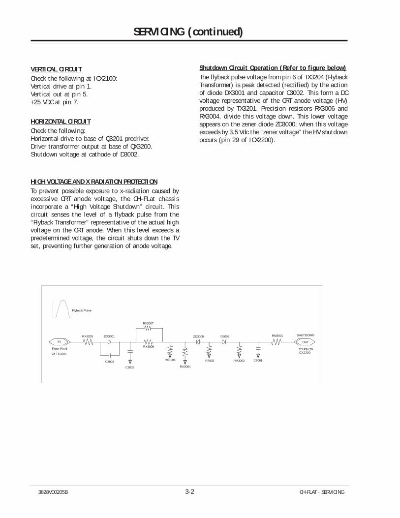
3828VD0205B 3-2 CH-FLAT - SERVICING
VERTICAL CIRCUITCheck the following at ICX2100:Vertical drive at pin 1.Vertical out at pin 5.+25 VDC at pin 7.
HORIZONTAL CIRCUITCheck the following:Horizontal drive to base of Q3201 predriver.Driver transformer output at base of QX3200.Shutdown voltage at cathode of D3002.
HIGH VOLTAGE AND X RADIATION PROTECTIONTo prevent possible exposure to x-radiation caused byexcessive CRT anode voltage, the CH-FLat chassisincorporate a “High Voltage Shutdown” circuit. Thiscircuit senses the level of a flyback pulse from the“Flyback Transformer” representative of the actual highvoltage on the CRT anode. When this level exceeds apredetermined voltage, the circuit shuts down the TVset, preventing further generation of anode voltage.
SERVICING (continued)
Shutdown Circuit Operation (Refer to figure below)The flyback pulse voltage from pin 6 of TX3204 (FlybackTransformer) is peak detected (rectified) by the actionof diode DX3001 and capacitor C3002. This form a DCvoltage representative of the CRT anode voltage (HV)produced by TX3201. Precision resistors RX3006 andRX3004, divide this voltage down. This lower voltageappears on the zener diode ZD3000; when this voltageexceeds by 3.5 Vdc the “zener voltage” the HV shutdownoccurs (pin 29 of ICX2200).
Flyback Pulse
IN
RX3209
C3003
DX3001
RX3007
RX3006
RX3005
C3002
ZD3000
R3003
D3002
RM3002 C3001
RM3001 SHUTDOWN
TO PIN 29ICX2200Of TX3201
From Pin 6
OUT
RX3004
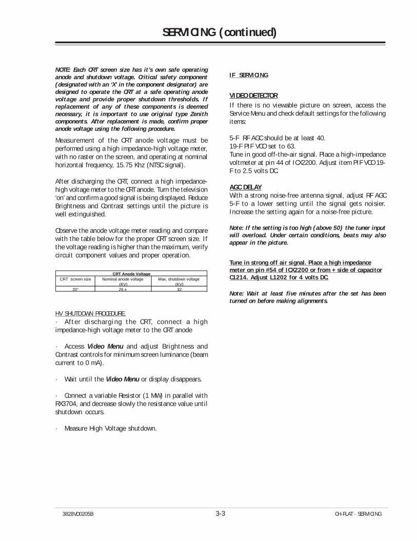
3828VD0205B 3-3 CH-FLAT - SERVICING
SERVICING (continued)
NOTE: Each CRT screen size has it’s own safe operatinganode and shutdown voltage. Critical safety component(designated with an ‘X’ in the component designator) aredesigned to operate the CRT at a safe operating anodevoltage and provide proper shutdown thresholds. Ifreplacement of any of these components is deemednecessary, it is important to use original type Zenithcomponents. After replacement is made, confirm properanode voltage using the following procedure.
Measurement of the CRT anode voltage must beperformed using a high impedance-high voltage meter,with no raster on the screen, and operating at nominalhorizontal frequency, 15.75 Khz (NTSC signal).
After discharging the CRT, connect a high impedance-high voltage meter to the CRT anode. Turn the television‘on’ and confirm a good signal is being displayed. ReduceBrightness and Contrast settings until the picture iswell extinguished.
Observe the anode voltage meter reading and comparewith the table below for the proper CRT screen size. Ifthe voltage reading is higher than the maximum, verifycircuit component values and proper operation.
CRT screen size Nominal anode voltage Max. shutdown voltage (KV) (KV)
20" 26 ± 32
CRT Anode Voltage
HV SHUTDOWN PROCEDURE.· After discharging the CRT, connect a highimpedance-high voltage meter to the CRT anode
· Access Video Menu and adjust Brightness andContrast controls for minimum screen luminance (beamcurrent to 0 mA).
· Wait until the Video Menu or display disappears.
· Connect a variable Resistor (1 MW) in parallel withRX3704, and decrease slowly the resistance value untilshutdown occurs.
· Measure High Voltage shutdown.
IF SERVICING
VIDEO DETECTORIf there is no viewable picture on screen, access theService Menu and check default settings for the followingitems:
5-F RF AGC should be at least 40.19-F PIF VCO set to 63.Tune in good off-the-air signal. Place a high-impedancevoltmeter at pin 44 of ICX2200. Adjust item PIF VCO 19-F to 2.5 volts DC.
AGC DELAYWith a strong noise-free antenna signal, adjust RF AGC5-F to a lower setting until the signal gets noisier.Increase the setting again for a noise-free picture.
Note: If the setting is too high (above 50) the tuner inputwill overload. Under certain conditions, beats may alsoappear in the picture.
Tune in strong off air signal. Place a high impedancemeter on pin #54 of ICX2200 or from + side of capacitorC1214. Adjust L1202 for 4 volts DC.
Note: Wait at least five minutes after the set has beenturned on before making alignments.
3828VD0205B 3-4 CH-FLAT - SERVICING
G2 ADJUSTMENTUse the following procedure when resetting G2.1. Set Brightness and contrast in the Video menu to
mid range.2. Set color level minimum.3. Connect the output of an NTSC generator to the
antenna input on the receiver.4. Select a color bar signal and turn color off. Adjust
the G2 control so that the range of bar patternstart from completely withe (not overdriven) toblack. Let visible 6 of 8 bars.
5. Return color level control to its normal setting.
FOCUS ADJUSTMENT
1. Connect the output of a NTSC generator to theantenna input on the receiver.
2. Select white raster pattern.3. Push menu key of remote control to observe the OSD.4. Adjust focus potentiometer to obtain the best focus
at letters of menu.
ADJUSTMENT OF RGB CUTOFFNOTE: If the Main module or the CRT has been replaced, G2 must be readjusted before adjusting the RGB Cutoff.
1. Enter the Service menu to gain access to thecutoff adjustments. (Factory mode item 00 must
be set to 1 to gain access to this adjustment).2. Set G Gain (Green) and B Gain (Blue) registers in the
Service menu to the default setting for the screensize as listed in the service menu. See table.
3. Set color level and contrast to minimum. Set tint tomid range.
4. Connected the output of NTSC generator to theantenna input of the receiver. Set the generator toa pure white signal, chroma off.
5. Set Factory menu registers #21, #22 and #23 to adjust cutoff controls.
6. Carefully observe which color is predominant on theCRT, Red, Green or Blue. Do not change thevalue of cutoff control of this color.
7. Adjust the other two cutoff controls to obtain colorbalance on the screen.
8. Select the color bars pattern from the Video generatorand turn the chroma off. Check that the TV setdisplays 3/4 of gray scale from white to black. Ifblack level is too high, readjust, register #27, RFBrightness. Do not move Aux. B offset.
9. Return the color level control to preset.10.Disable the factory menu (Factory Mode item 0 must
be set to 0). Select “Preset” in the Video Menu underpicture preference.
SERVICING (continued)
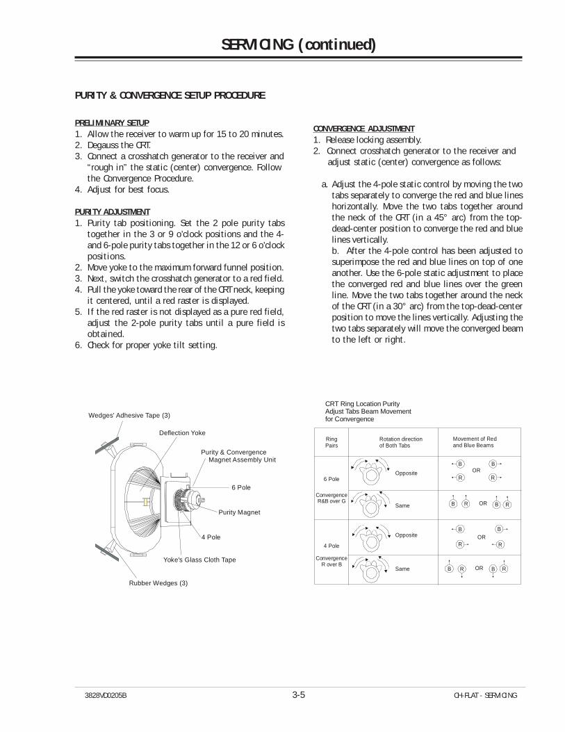
3828VD0205B 3-5 CH-FLAT - SERVICING
PRELIMINARY SETUP1. Allow the receiver to warm up for 15 to 20 minutes.2. Degauss the CRT.3. Connect a crosshatch generator to the receiver and
“rough in” the static (center) convergence. Followthe Convergence Procedure.
4. Adjust for best focus.
PURITY ADJUSTMENT1. Purity tab positioning. Set the 2 pole purity tabs
together in the 3 or 9 o’clock positions and the 4-and 6-pole purity tabs together in the 12 or 6 o’clockpositions.
2. Move yoke to the maximum forward funnel position.3. Next, switch the crosshatch generator to a red field.4. Pull the yoke toward the rear of the CRT neck, keeping
it centered, until a red raster is displayed.5. If the red raster is not displayed as a pure red field,
adjust the 2-pole purity tabs until a pure field isobtained.
6. Check for proper yoke tilt setting.
CONVERGENCE ADJUSTMENT1. Release locking assembly.2. Connect crosshatch generator to the receiver and adjust static (center) convergence as follows:
a. Adjust the 4-pole static control by moving the twotabs separately to converge the red and blue lineshorizontally. Move the two tabs together aroundthe neck of the CRT (in a 45° arc) from the top-dead-center position to converge the red and bluelines vertically.b. After the 4-pole control has been adjusted tosuperimpose the red and blue lines on top of oneanother. Use the 6-pole static adjustment to placethe converged red and blue lines over the greenline. Move the two tabs together around the neckof the CRT (in a 30° arc) from the top-dead-centerposition to move the lines vertically. Adjusting thetwo tabs separately will move the converged beamto the left or right.
PURITY & CONVERGENCE SETUP PROCEDURE
Yoke's Glass Cloth Tape
Wedges' Adhesive Tape (3)
Rubber Wedges (3)
Deflection Yoke
Purity & Convergence Magnet Assembly Unit
6 Pole
Purity Magnet
4 Pole
RingPairs
6 Pole
ConvergenceR&B over G
ConvergenceR over B
4 Pole
Rotation directionof Both Tabs
Opposite
Opposite
Same
Same
Movement of Redand Blue Beams
B
B B
R R
B BR R
B
R ROR
OR
OR
B BR ROR
CRT Ring Location PurityAdjust Tabs Beam Movementfor Convergence
SERVICING (continued)
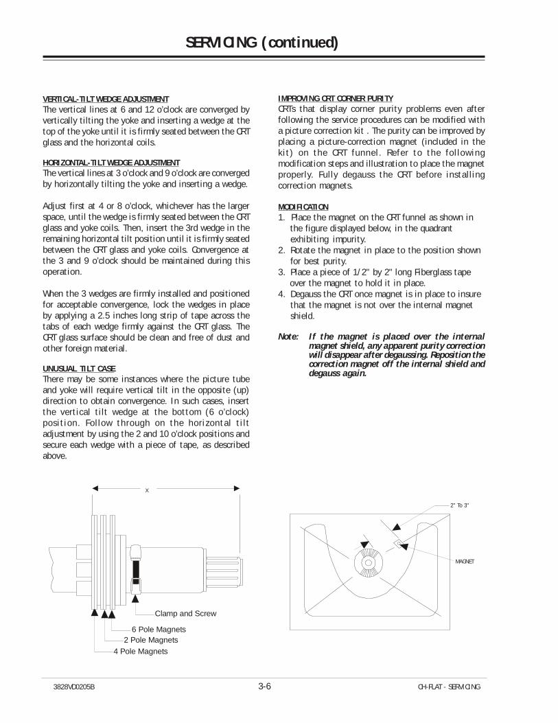
3828VD0205B 3-6 CH-FLAT - SERVICING
SERVICING (continued)
VERTICAL-TILT WEDGE ADJUSTMENTThe vertical lines at 6 and 12 o’clock are converged byvertically tilting the yoke and inserting a wedge at thetop of the yoke until it is firmly seated between the CRTglass and the horizontal coils.
HORIZONTAL-TILT WEDGE ADJUSTMENTThe vertical lines at 3 o’clock and 9 o’clock are convergedby horizontally tilting the yoke and inserting a wedge.
Adjust first at 4 or 8 o’clock, whichever has the largerspace, until the wedge is firmly seated between the CRTglass and yoke coils. Then, insert the 3rd wedge in theremaining horizontal tilt position until it is firmly seatedbetween the CRT glass and yoke coils. Convergence atthe 3 and 9 o’clock should be maintained during thisoperation.
When the 3 wedges are firmly installed and positionedfor acceptable convergence, lock the wedges in placeby applying a 2.5 inches long strip of tape across thetabs of each wedge firmly against the CRT glass. TheCRT glass surface should be clean and free of dust andother foreign material.
UNUSUAL TILT CASEThere may be some instances where the picture tubeand yoke will require vertical tilt in the opposite (up)direction to obtain convergence. In such cases, insertthe vertical tilt wedge at the bottom (6 o’clock)position. Follow through on the horizontal tiltadjustment by using the 2 and 10 o’clock positions andsecure each wedge with a piece of tape, as describedabove.
X
4 Pole Magnets
Clamp and Screw
6 Pole Magnets2 Pole Magnets
IMPROVING CRT CORNER PURITYCRTs that display corner purity problems even afterfollowing the service procedures can be modified witha picture correction kit . The purity can be improved byplacing a picture-correction magnet (included in thekit) on the CRT funnel. Refer to the followingmodification steps and illustration to place the magnetproperly. Fully degauss the CRT before installingcorrection magnets.
MODIFICATION1. Place the magnet on the CRT funnel as shown in the figure displayed below, in the quadrant
exhibiting impurity.2. Rotate the magnet in place to the position shown
for best purity.3. Place a piece of 1/2" by 2" long Fiberglass tape over the magnet to hold it in place.4. Degauss the CRT once magnet is in place to insure
that the magnet is not over the internal magnetshield.
Note: If the magnet is placed over the internalmagnet shield, any apparent purity correctionwill disappear after degaussing. Reposition thecorrection magnet off the internal shield anddegauss again.
2" To 3"
MAGNET
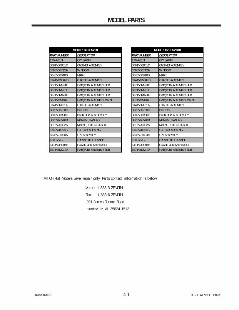
3828VD0205B 4-1 CH - FLAT MODEL PARTS
MODEL PARTS
PART NUMBER DESCRIPTION PART NUMBER DESCRIPTION
170-A01N CPT EARTH 170-A01N CPT EARTH
3091V00B81D CABINET ASSEMBLY 3091V00B81D CABINET ASSEMBLY
3790V00712A WINDOW 3790V00712A WINDOW
3846V00048B MARK 3846V00048B MARK
3141VMNP47D CHASSIS ASSEMBLY 3141VMNP47D CHASSIS ASSEMBLY
6871VSMV74C PWB(PCB) ASSEMBLY,SUB 6871VSMV74C PWB(PCB) ASSEMBLY,SUB
6871VSMV75C PWB(PCB) ASSEMBLY,SUB 6871VSMV75C PWB(PCB) ASSEMBLY,SUB
6871VSMW20K PWB(PCB) ASSEMBLY,SUB 6871VSMW20K PWB(PCB) ASSEMBLY,SUB
6871VMMP46E PWB(PCB) ASSEMBLY,MAIN 6871VMMP46E PWB(PCB) ASSEMBLY,MAIN
3141VSNC61A CHASSIS ASSEMBLY 3141VSNC61A CHASSIS ASSEMBLY
5020V00780C BUTTON 5020V00780C BUTTON
3809V00B08C BACK COVER ASSEMBLY 3809V00B08C BACK COVER ASSEMBLY
3828VA0518B MANUAL,OWNERS 3828VA0518B MANUAL,OWNERS
5016V20002A MAGNET,STICK FERRITE 5016V20002A MAGNET,STICK FERRITE
6140VC8004B COIL,DEGAUSSING 6140VC8004B COIL,DEGAUSSING
6335V21020A CPT ASSEMBLY 6335V21A04H CPT ASSEMBLY
120-C77G SPEAKER,FULLRANGE 120-C77G SPEAKER,FULLRANGE
6411VUH004B POWER CORD ASSEMBLY 6411VUH004B POWER CORD ASSEMBLY
6871VSMV19A PWB(PCB) ASSEMBLY,SUB 6871VSMV19A PWB(PCB) ASSEMBLY,SUB
MODEL: H20H52DT MODEL: H20H52DT8
All CH Flat Models Level repair only. Parts contact information is below.
Voice: 1-888-3-ZENITH
Fax: 1-888-6-ZENITH
201 James Record Road
Huntsville, AL 35824-1513
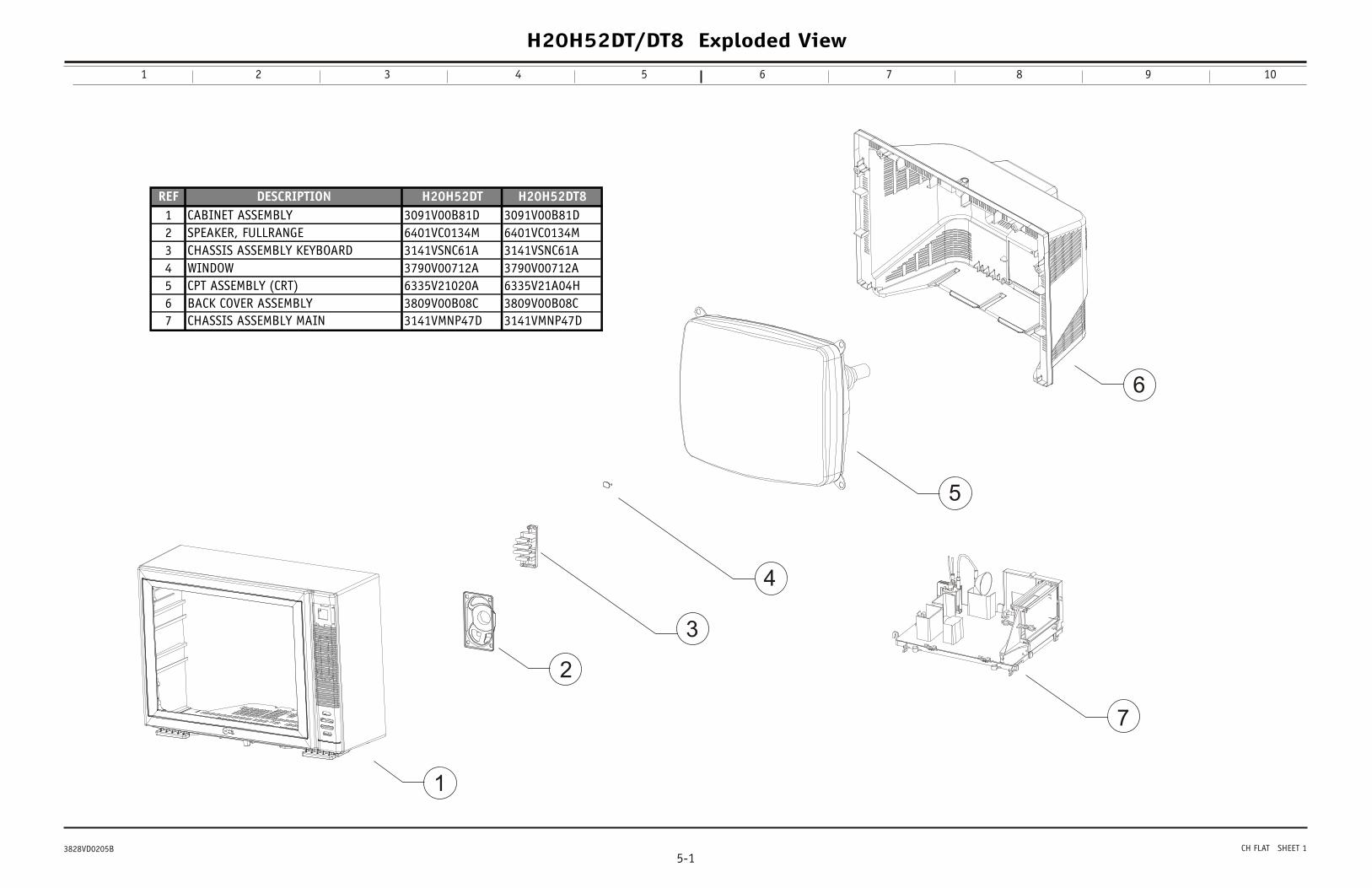
1
2
3
5
4
6
7
H20H52DT/DT8 Exploded View
5-13828VD0205B CH FLAT SHEET 1
1 2 3 4 5 6 7 8 9 10
REF DESCRIPTION H20H52DT H20H52DT81 CABINET ASSEMBLY 3091V00B81D 3091V00B81D2 SPEAKER, FULLRANGE 6401VC0134M 6401VC0134M3 CHASSIS ASSEMBLY KEYBOARD 3141VSNC61A 3141VSNC61A4 WINDOW 3790V00712A 3790V00712A5 CPT ASSEMBLY (CRT) 6335V21020A 6335V21A04H6 BACK COVER ASSEMBLY 3809V00B08C 3809V00B08C7 CHASSIS ASSEMBLY MAIN 3141VMNP47D 3141VMNP47D
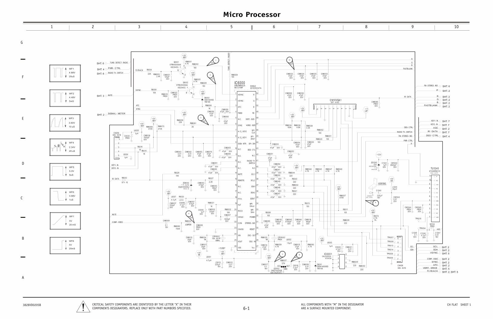
Micro Processor
1 2 3 4 5 6 7 8 9 10
G
D
C
B
E
F
A
6-1CRITICAL SAFETY COMPONENTS ARE IDENTIFIED BY THE LETTER “X” IN THEIRCOMPONENTS DESIGNATORS. REPLACE ONLY WITH PART NUMBERS SPECIFIED.
ALL COMPONENTS WITH “M” IN THE DESIGNATORARE A SURFACE MOUNTED COMPONENT.
3828VD0205B CH FLAT SHEET 1
SYNC
AFC
FLYB AC K
VSYNC
TUNE- DETEC T- RADIO
PWR- C TRL
RADIO/ TV- SWITC H
MUTE
SIGNAL- METER + 5 VSB F
+ 5 VSB F
+
+ 5 VSB F
+ 5 VSB F
RM
RM6 0 0 32 .4 K
R6 0 0 4
2 2 K
R6 0 0 8
10 K
RM6 0 6 94 7 0 K
RM6 0 7 04 7 0 K
RM6 0 10PROV
1
2
3
4
5
C N2 K63 6 6 - 9 2 1D
1
L6 0 0 4
1µ H
RM6 0 5 82 2 K
R6 0 16
1K
C M6 0 2 2
5 0 VPROV
C M6 0 4 3
2 5 V0 .0 1
C M6 0 4 2
2 5 V0 .0 1
C M6 0 0 1
5 0 V12 0 pF
RM6 0 0 14 .7 K
C 6 0 3 5PROV
L6 0 0 5
1µ H
R6 0 15
1K
Q6 0 0 2
B
0 TR9 4 5 0 0 9 AAKSC 9 4 5 C - Y
Q6 0 0 1
E
BC
0 TR9 4 5 0 0 9 AAKSC 9 4 5 C - Y
C M6 0 3 6
5 0 V10 0 0 pF
MUTE
C OMP- VIDEO
KEY1- IN
IR- DATA
KEY2 - IN
+ 5 VSB F
+ 5 VSB F+ 5 V
SB
+ 5 VSB F
W6 0 0 2
9 7 1- 16
C M6 0 0 5
5 0 V2 2 0 pF
RM6 0 3 3
JUMPER
ZD6 0 0 29 .1V
0 DZ9 10 0 0 9 AJMTZJ9 .1B
1/ 2 W
RM6 0 3 2
15 K
C M6 0 0 8PROV5 0 V
C M6 0 0 7
10 0 0 pF5 0 V
C 6 0 13
16 V2 2 0 µ F
RM6 0 8 07 5 0 K
C M6 0 0 9
16 V0 .1
C 6 0 9 8
5 0 V4 .7 µ F
R6 0 3 0
JUMPER
C M6 0 9 74 7 0 pF
5 0 V
RM6 0 3 1
1K
C 6 0 0 6
5 0 V1µ F
17
18
19
2 0
2 1
2 2
2 3
2 4
2 5
16
15
C VIN
VHOLD
2 6
RVC O
HLF
VSS
XOUT
XIN
S
AVcc
C NVSS
REMOTE
N.C .
N.C .
L6 0 0 7
4 .7 µ H
R6 0 2 6
10 K
C RY6 0 0 115 6 - A0 1P
8 MHz
L6 0 0 1
4 .7 µ H
R6 0 2 7
2 .2 KC M6 0 0 3
5 0 V4 7 0 pF
C M6 0 10
5 0 V2 0 pF
C M6 0 11
5 0 V2 0 pF
C M6 0 12
2 5 V0 .0 1
C M6 0 3 7
5 0 V2 2 0 pF
C M6 0 4 0
5 0 V18 0 pF
RM6 0 3 41M
RADIO/ TV- SWITC H
FASTB LANK
DEG- C TRL
PWR- C TRL
GB
R
IF
FM- STEREO- IND
IR- DATA
IF
B
DEG - C TRL
FASTB LANK
R
G
IR - DATA
AGC
KEY2 - IN
KEY1- IN
FM- STEREO- IND
LSP+ 11
+ 3 3 V
C M6 0 8 0PROV
5 0 V
C 12 4 1
5 0 V1µ F
C M12 4 2
5 0 V6 8 0 0 pF
ZD12 4 03 3 V
1/ 2 W
0 DZ3 3 0 0 0 9 DF
MTZJ3 3 B TU12 4 06 7 0 0 NFNS11C
TAEU- H0 0 1P
123458 7 69
C N10 VGA1
1
3 8 7 - A10 C
M6 0 3 3
5 0 V4 7 pF
0
RM6 0 4 74 .7 K
RM6 0 4 84 .7 K
RM6 0 5 1
10 0
5 2
TUN
E-D
ETEC
T-R
AD
IO
+ 5 VSB F
+ 5 VSB F
+ 5 VSB F
5 VSB F
+ 5 VSB F
RM6 0 0 910 0
RM6 0 0 2
18 0
6 0 6 1
2 K
C M6 0 3 8
5 0 V4 7 pF
C M6 0 6 0
5 0 V4 7 pF
C M6 0 5 95 0 V4 7 pFC M6 0 5 8
5 0 V4 7 pF
RM6 0 0 54 .7 K
RM6 0 9 0
1K
D6 0 0 20 DD4 14 8 0 9 ED1N4 14 8
RM6 0 0 6
15 0
C M6 0 0 2
5 0 V4 7 pFC M6 0 7 9
5 0 V4 7 pF
C M6 0 9 3
5 0 V4 7 pF C M6 0 9 0
5 0 V4 7 pF
3 914
4 6
4 5
4 4
4 3
4 2
4 1
4 013
12
11
10
9
8
7
5 2
5 1
5 0
4 9
4 8
4 76
5
4
3
2
1
G
R
B
FB
N.C .SWITC H
VERT- SIZE
N.C .
N.C .
MUTE
A/ D_ KEY1
SC L1
DEG- C TL
SPI- DIN
A/ D_ KEY2
AFC
HSYNC
SIGN- MTR
N.C .
SP1C LK
N.C .
RADIO/ TV
HORZ- SIZESYNC
VSYNC
N.C .
N.C .
SP1DOUT
FMSD
IC 6 0 0 0M3 7 2 7 6 MF
1
0 IMC RMI0 4 2 A
C M6 0 9 5
5 0 V4 7 pF
RM6 0 3 66 .8 K
C M6 0 5 44 7 pF5 0 V
RM6 0 1410 0 K
E
C
10
SHIELD4 8 14 V0 0 3 4 7 A
C M6 0 2 3
5 0 V4 7 pF
C M6 0 2 4
5 0 V4 7 pF
C M6 0 2 5
5 0 V4 7 pF
C
C M6 0 4 1
4 7 pF 5 0 VC M6 0 5 0
C M6 0 5 1
4 7 pF5 0 V
C M6 0 5 2
4 7 pF5 0 V
C M6 0 5 3
4 7 pF 5 0 V
C M6 0 5 54 7 pF5 0 V
C M60 9 1
5 0 V4 7 pFC M6 0 9 2
5 0 V4 7 pF
C M6 0 9 4
4 7 pF 5 0 V
RM6 0 3 83 .3 K
RM6 0 4
10 0
RM6 0 4 4
2 2 0
RM6 0 4 54 .7 K
RM6 0 4 64 .7 K
RM6 0
10 0
+ 5 VSB F
+ 5 VSB F
+ 5 VSB F
RM6 0 0 74 7 0 K
R6 0 9 9
10 0
RM6 0 3 9
2 2 0
3 4
3 5
3 6
3 7
3 8
2 8
2 9
3 0
3 1
3 2
3 3
2 7
POWER
OSC - IN
MPIDAout
OSC - OUT
MPIDAin
Vcc
IDENT
RESET
SDA2
TEREO- IND
SDA1
SC L2
R6 0 11
10 0
R6 0 13
10 0
C 6 0 16
5 0 V2 .2 µ F
D6 0 0 10 DD4 14 8 0 9 ED1N4 14 8
8
7
6
54
3
2
1IC 6 0 0 1
AT2 4 C 0 8
14
0 IAL2 4 0 8 0 0 A
IC 6 0 0 2
KIA7 0 4 2 P( AT)
GND
VC C OUT
0 IKE7 0 4 2 0 0 B
L6 0 0 2
1.8 µ H
C 6 0 2 0
5 0 V4 .7 µ F
L6 0 0 3
1µ H
R6 0 4 1
2 2 0
R6 0 4 3
2 2 0
C RY6 0 0 2PROV
C M6 0 14
5 0 V2 7 pF
C M6 0 15
5 0 V2 7 pF
C M6 0 17
16 V0 .1
C M6 0 1810 0 0 pF
5 0 V
C M6 0 19
5 0 V18 0 pF
C M6 0 2 1
2 5 V0 .0 1
4 7 pF 5 0 VC M6 0 4 9
4 7 pF 5 0 VC M6 0 4 8
4 7 pF 5 0 VC M6 0 4 7
4 7 pF 5 0 V
C M6 0 4 6
5 0 V4 7 pF
C M6 0 4 5
5 0 V4 7 0 0 pF
C M6 0 5 6
2 5 V0 .0 1
C M6 0 9 9
5 0 V4 7 pF
RM6 0 3 51M
RM6 0 3 7
2 7 K
RM6 0 4 2
2 2 0
RM6
2 2
RM6 0 5 94 .7 K
RM6 0 6 04 .7 K SC L
SDA
AGC
VSYNC
FLYB AC K
SC L
SDA
SYNC
AFC
VERT- DRIVE
C OMP- VIDEO
+ 5 VSB F
+ 5 VSW
C 12 4 0
2 2 0 µ F16 V
R6 0 7 24 .7 K1%
L12 4 03 3 µ H
HOSPGND6 6 3 0 UZ0 2 6 0 1
C NGND1
3 8 7 - 9 0 7 E C M12 4 3
2 5 V0 .0 1
C 12 4 6
5 0 V4 .7 µ F
C M12 4 5PROV
5 0 V
C M12 4 4PROV
5 0 V
3
10
11
5 V
9
8
7
6
5
4
5 V
NC
1
SC L
SDA
AS
NC
AGC
2
NC
IF
3 3 V
1
5
4
3
2
1
6
C N4 G93 6 6 - 9 2 1E
1
0 4 9
0 RM6 0 5 0
2 2 0
C 12 4 7
16 V0 .0 1
W12 5 0PROV
C 12 4 9
5 0 V0 .1
TP6 0 0 4
TP6 0 10
TP6 0 14
TP6 0 0 7
TP6 0 0 6
TP6 0 0 8
TP6 0 0 9
TP6 0 13
SHT. 6
SHT. 6
SHT. 4
SHT. 3
SHT. 2
SHT. 6
SHT. 2
SHT. 2
SHT. 2
SHT. 2
SHT. 2
SHT. 7
SHT. 7
SHT. 2
SHT. 7
SHT. 4
SHT. 2
SHT. 2
SHT. 5
SHT. 2
SHT. 2SHT. 2
SHT. 5
SHT. 2, SHT. 5
WF
1
WF
2
WF
3
WF
4
WF
5
FW 6
WF
7
WF
8
10 uS
3.60V
WF3
5uS
5.0V
WF5
20 uS
2.34V
WF4
1uS
WF6
4.88V
4.48V
5mS
WF2
4.88V
20uS
WF1
20 mS
WF7
5V
20mS
5V
WF8
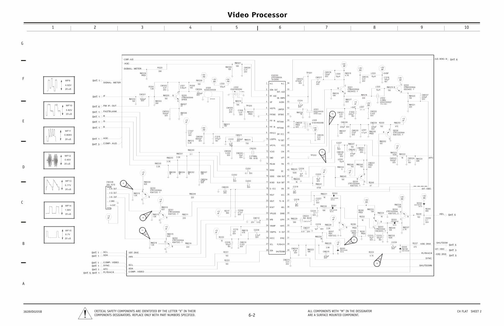
Video Processor
1 2 3 4 5 6 7 8 9 10
G
D
C
B
E
F
A
6-2CRITICAL SAFETY COMPONENTS ARE IDENTIFIED BY THE LETTER “X” IN THEIRCOMPONENTS DESIGNATORS. REPLACE ONLY WITH PART NUMBERS SPECIFIED.
ALL COMPONENTS WITH “M” IN THE DESIGNATORARE A SURFACE MOUNTED COMPONENT.
3828VD0205B CH FLAT SHEET 2
SIGNAL- METER
C OMP- AUD
AGC
B
R
AGC
IF
G
FM/ IF- OUT
SIGNAL- METER
C OMP- AUD
FASTB LANK
VF+ 9
Q12 0 0
E
B
C
0 TR9 5 9 0 0 9 AAB F9 5 9
C M12 0
5 0 V6 8 0 0 pF
RM12 123 .3 K
RM12 2 6PROV
R12 0 910 0
RM12 0
10 0L12 0 10 .8 2 µ H
C 12 0 7
5 0 V0 .4 7
RM12 0 72 2
RM12 0 5
10 0RM12 0 33 9 0
RM12 0 83 3
R12 0 41.5 K
RM12 0 210 0
C M12 0
5 0 V10 0 0 p
C M12 0 2
2 5 V0 .0 1
C M12 0 3
5 0 V10 0 0 pF
C M12 0 1
5 0 V10 0 0 pF
R12 2 5
3 9 K
RM2 2
3 9 0
C 2
5 01µ F
RM2 2
10 0
C M2 2 13
2 5 V0 .0 1
C M2 2
5 04 7 p
RM
C
51
3 4
3 3
3 2
3 1
3 0
2 9
1
2
3
4
5
4 1
4 0
3 9
3 8
3 7
3 6
3 5
6
7
8
9
10
11
12
13
4 9
4 8
4 7
4 6
4 5
4 4
4 3
4 2
14
15
17
16
18
19
2 0
2 1
5 6
5 5
5 4
5 3
5 2
5 1
5 0
2 2
2 3
2 4
2 5
2 6
2 7
2 8
N.C .
SDN- OUT
GOSD
SIF
AGC FIL
RF- AGC
N.C .
EXT- AUD
DE- EMPH
AUDIN
LIMITER
PIFGND
PIF- IN
PIF- IN
PIFVC C
LOOPFIL
SIFGND
PIFTANK
PIFTANK
SIF/ VC C
TV/ DET
APC FIL VC C
VC XO C IN
AFT
YIN
DC
GND
FB LNK
ROSD
B OSD
D- VC C
ROUT
SHUTDOWN
B OUT
GOUT
VSW- OUT
B LK/ DET
VIN
AC L
TV- IN
AB L
VPULSE
NFB
VRAMP
VSEPFIL
HVC C
SC L
DGND
3 2 FH
HAFC
H- OUT
SYNC
FLYB AC K
SDA
IC X2 2 0 00 ITO12 6 8 0 0 A
1
TA12 6 8 N
C OMP- VIDEO
VERT- DRIVE
VNFB
C OMP- VIDEO
AFC
SYNC
FLYB AC K
SDA
SC L
VF+ 9
VF+ 9
VF+ 9
VF+ 9
+ 9 VF
GND
B - OUT
G- OUT
R- OUT5
4
3
2
1
C N2 C 5 B
1
3 6 6 - 9 2 1D
SC L
RM2 2 0 1
3 .3 K
R 2 2 0 0
0 .1
RM2 2 0 3
3 .3 KRM2 2 0 5
3 .3 K
RM2 2 0 61K
RM2 2 0 41K
RM2 2 0 21K
RM2 2 0 8
2 2 0
RM2 2 0 98 2 0
RM2 2 101.5 K
RM2 2 128 2 0
RM2 2 131.5 K
SDA
RM2 2 158 2 0
RM2 2 161.5 K
RM2 2 14
2 2 0
RM2 2 11
2 2 0
Q2 2 0 0
E
BC
0 TR7 3 3 0 0 9 AAKSA7 3 3 C - Y
Q2 2 0 1
E
BC
0 TR7 3 3 0 0 9 AAKSA7 3 3 C - Y
Q2 2 0 2
E
BC
0 TR7 3 3 0 0 9 AAKSA7 3 3 C - Y
VF+ 9
VF+ 9
15 6 - A0 1B3 .5 7 9 MHz
R2 2 2 1
10 0
C M2 2 10
5 0 V0 .0 2 2
C M12 0 8
5 0 V0 .0 2 2
C 2 2 0 1
5 0 V0 .1C 2 2 0 2
5 0 V0 .1
C 2 2 0 3
5 0 V0 .1
C M2 2 0 5
2 5 V0 .0 1
C 2 2 0 8
5 0 V2 .2 µ F
C M2 2 0 0
5 0 V12 pF
C 2 2 0 9
16 V10 0 µ F
C 2 110
5 0 V1µ F RM2 113
4 7 K
RM2 2 0 710 K
C M2 2 0 4
5 0 V4 7 pF
R2 2 2 0
10
R2 2 2 2
10 0
R2 2 175 6 0
C 2 2 0 6
5 0 V4 .7 µ F
C M2 112
2 5 V 0 .0 1
SYNC
SHUTDOWN
FLYB AC K
HORZ- DRIVE
EXT- VIDEO
SHUTDOW
HORZ- DRIVE
EXT- VIDEO
AB L
SW+ 9 V
SW+ 9 V
VF+ 9
VF+ 9
SW+ 9 V
Q2 2 0 3
E
B
C0 TR9 4 5 0 0 9 AAKSC 9 4 5 C - Y
R2 2 4 9
4 7
2 9
D2 2 0 2
0 DD4 14 8 0 9 ED1N4 14 8
C M2 2 15
5 0 V4 7 0 pF
RM2 2 2 5
3 .9 K
2 19
V
5 0 Vµ
D2 2 0 00 DD4 14 8 0 9 ED1N4 14 8
RM2 2 4 1
4 7 0 K
14
VF RM2 2 2 3
15 K
RM2 2 3 0
10 KC 2 2 2 0
5 0 V0 .1
C 2 2 2 1
5 0 V0 .1
1K
D2 2 0 40 DD4 14 8 0 9 ED
1N4 14 8
C R2 2 0 116 6 - E0 2 G
C SB 5 0 3 F3 0
R2 2 3 9
10 0
RM2 2 3 313 K
C 2 2 2 4
5 0 V0 .1
10 0
C M2 2 17
2 5 V0 .0 1
R2 2 3 2
1K
RM2 2 3 1
1K
R2 2 9 2PROV
2 2 18
0 Vµ F
D2 2 0 1
0 DD4 14 8 0 9 ED1N4 14 8
RM2 2 2 61K
RM2 2 2 8
2 .2 K
C 2 2 16
5 0 V1µ F RM2 2 3 610 K
D2 2 0 30 DD4 14 8 0 9 ED
1N4 14 8
R2 2 9 1PROV
R2 2 9 0
PROV RM2 2 3 72 .7 K
RM2 2 3 4
1K
C 2 2 9 0
2 5 VPROV
R2 2 4 06 8 0
C 2 2 2 3
16 V10 0 µ F
C 2 2 2 2
5 0 V10 µ F
RM2 2 3 510 0 K
Q2 2 0 7
E
BC
PROVKSA7 3 3 C - Y
Q2 2 0 5 C0 TR7 3 3 0 0 9 AA
KSA7 3 3 C - Y
Q2 2 0 4E
BC
0 TR7 3 3 0 0 9 AAKSA7 3 3 C - Y
RM2 2 3 81.6 K
R2 2 2 7
4 7 0
R2 2 2 4
4 .7 K
C 2 2 3 9
5 0 V4 .7 µ F D2 2 0 5
1N4 14 80 DD4 14 8 0 9 ED
+ 9 VPIF
+ 9 VPIF
+ 9 VPIFSW
+ 9 V
RM12 10
10 K
C R2 2 0 0
9
RM12 3 1PROV
RM12 1110 K
6
RM12 13
7 5 0
C 12 12
5 0 V0 .4 7
C 12 10
16 V4 7 0 µ F
L12 0 0
12 0 µ H L12 0 26 14 0 VH0 0 0 9 A
4 .5 MHz
C M12 11
5 0 V10 0 0 pF
M
U12 0 06 2 0 0 C 0 0 0 0 2 8
M19 6 2 M
C M12 0 0
2 5 V0 .0 1
C M12 0 5
2 5 V0 .0 1 C 12 0 6
5 0 V0 .4 7
4
F
RM12 0 1
10 KRM12 0 012 K
TP12 0 0
AUD- MONO- IN
+ 9 VSIF
SW+ 9 V
+ 9 VSIF
+ 9 VSIF
+ 9 VSIF
+ 9 VF
VF+ 9
SW+ 9 V
Q12 0 1
E
BC
0 TR9 4 5 0 0 9 AAKSC 9 4 5 C - Y
Q12 0 2
E
BC
0 TR9 4 5 0 0 9 AAKSC 9 4 5 C - Y
C M12 13
5 0 V4 7 0 0 pF
RM12 2 015 0
C 12 14
5 0 V4 .7 µ F RM12 2 1
2 2 0
C M12 18
5 0 V12 0 pF L12 0 4
10 µ H
L12 0 7-
C M2 2 3 7
5 0 V2 2 0 pF
RM12 154 .7 K
C M12 17
5 0 V4 7 pF
RM12 1610 K
RM12 178 2 0
RM12 18
2 2 0 U12 0 2
6 2 0 0 C 0 0 0 0 2 74 .5 MHz
TPS4 .5 MB 9
RM12 19
15 0
L12 0 5
12 µ H
C M12 15
2 5 V0 .0 1
L12 0 3
10 µ H C 12 16
16 V10 0 µ F
TP12 0 1
AFC
VF+ 9
VF+ 9
VF+ 9
VF+ 9
+ 9 VSIF
RM12 2 2
1K
R2 2 5 5
10 0
L12 0 66 14 0 VH0 0 0 9 B
RM2 2 5 73 9 K
RM2 2 5 210 0
C 2 2 2 5
10 F
C 2 2 2 6
5 0 V1µ F
RM12 141K
C 12 2 2
16 V2 2 0 µ F
9 7 1 16
4 3
K
RM12 2 43 9 K
C M2 2 3 6
5 0 V2 2 0 pF
2 2 4 2
C M2 2 9 2
5 0 V4 7 0 pF
C M12 19
2 5 V0 .0 1
U12 0 16 2 0 0 C 0 0 0 0 2 64 .5 MHzSFSH4 .5 MDB
RM2 2 4 5
RM2 2 4 815 0
C M12 2 4
16 V0 .1
C M2 2 2 5PROV5 0 V
RM12 2 310 0 K
C M12 2 1
2 5 V0 .0 1
C M12 2 3
5 0 V10 0 0 pF
C 2 2 2 7
5 0 V0 .1
C M2 2 3 1
5 0 VPROV
C M12 2 0
5 0 V0 .0 2 2
C M2 2 3 5
5 0 V2 7 pF
L2 2 0 14 .7 µ H RM2 2 5 6
PROV
C M2 2 3 4
5 0 V2 2 0 pF
RM2 2 5 3
4 7 0
RM2 2 4 615 0
C M2 2 2 8
5 0 V12 0 pF
L2 2 0 012 µ H
RM2 2 4 40
C M2 2 9 1
5 0 VPROV
RM2 2 4 7
10 0
E
B
Q2 2 0 6EB
C
KSA7 3 3 C - Y0 TR7 3 3 0 0 9 AA
TP12 0 3
SHT. 1
SHT. 6
SHT. 1
SHT. 1
SHT. 1
SHT. 1
SHT. 1
SHT. 1
SHT. 3
SHT. 1
SHT. 1
SHT. 1
SHT. 1
SHT. 1
SHT. 5, SHT. 1
SHT. 5
SHT. 5
SHT. 6
SHT. 3
SHT. 5
WF
9
WF
10
WF
11
WF
15
WF
14
FW
13
WF
1220 uS
WF10
3.82V
20 uS
WF9
4.62V
20 uS
WF11
0.808V
20 uS
WF14
1.68V
9.7V
WF15
20 uS
0.45V
WF12
20 uS
20 uS
WF13
0.77V
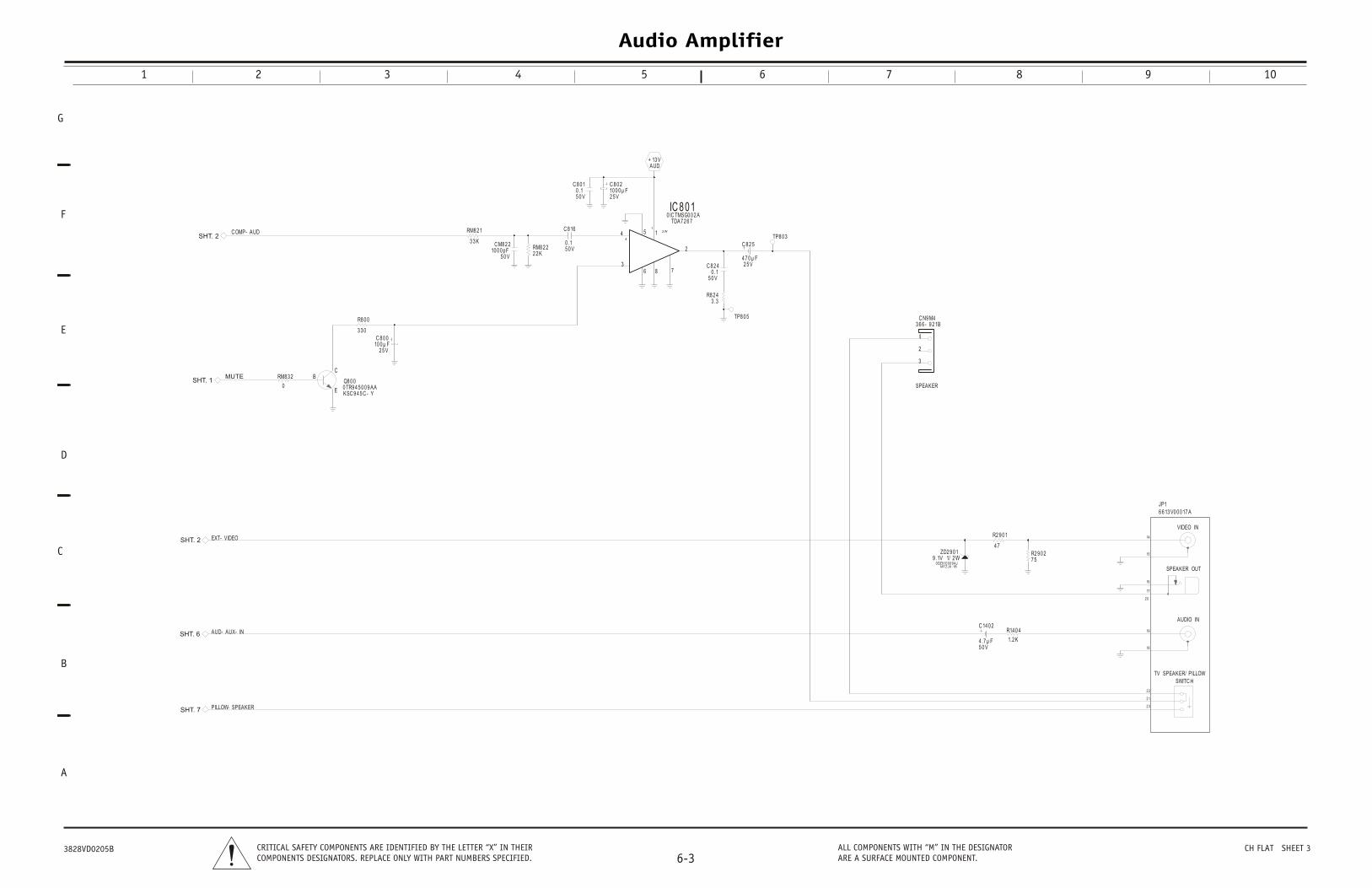
Audio Amplifier
1 2 3 4 5 6 7 8 9 10
G
D
C
B
E
F
A
6-3CRITICAL SAFETY COMPONENTS ARE IDENTIFIED BY THE LETTER “X” IN THEIRCOMPONENTS DESIGNATORS. REPLACE ONLY WITH PART NUMBERS SPECIFIED.
ALL COMPONENTS WITH “M” IN THE DESIGNATORARE A SURFACE MOUNTED COMPONENT.
3828VD0205B CH FLAT SHEET 3
EXT- VIDEO
PILLOW- SPEAKER
AUD- AUX- IN
C OMP- AUD
MUTE
AUD+ 13 V
C 14 0 2
5 0 V4 .7 µ F
R14 0 4
1.2 K
R2 9 0 1
4 7R2 9 0 27 5
ZD2 9 0 1
MTZJ9 .1B
1/ 2 W9 .1V0 DZ9 10 0 0 9 AJ
1
2
3
C N9 M43 6 6 - 9 2 1B
1
RM8 2 22 2 K
RM8 2 1
3 3 K C M8 2 210 0 0 pF
5 0 V
C 8 2 5
2 5 V4 7 0 µ F
C 8 0 2
2 5 V10 0 0 µ F
C 8 16
5 0 V0 .1
C 8 2 4
5 0 V0 .1
C 8 0 1
5 0 V0 .1
R8 2 43 .3
1
2
3
4 5
6 78
IC 8 0 1TDA7 2 6 7
0 IC TMSG0 0 2 A
12 W
4
RM8 3 2
0Q8 0 0
E
BC
KSC 9 4 5 C - Y0 TR9 4 5 0 0 9 AA
C 8 0 0
2 5 V10 0 µ F
R8 0 0
3 3 0
VIDEO IN
SPEAKER OUT
AUDIO IN
TV SPEAKER/ PILLOWSWITC H
14
15
16
17
18
19
2 0
2 1
2 2
2 3
JP16 6 13 V0 0 0 17 A
TP8 0 5
TP8 0 3
SPEAKER
SHT. 2
SHT. 1
SHT. 7
SHT. 2
SHT. 6
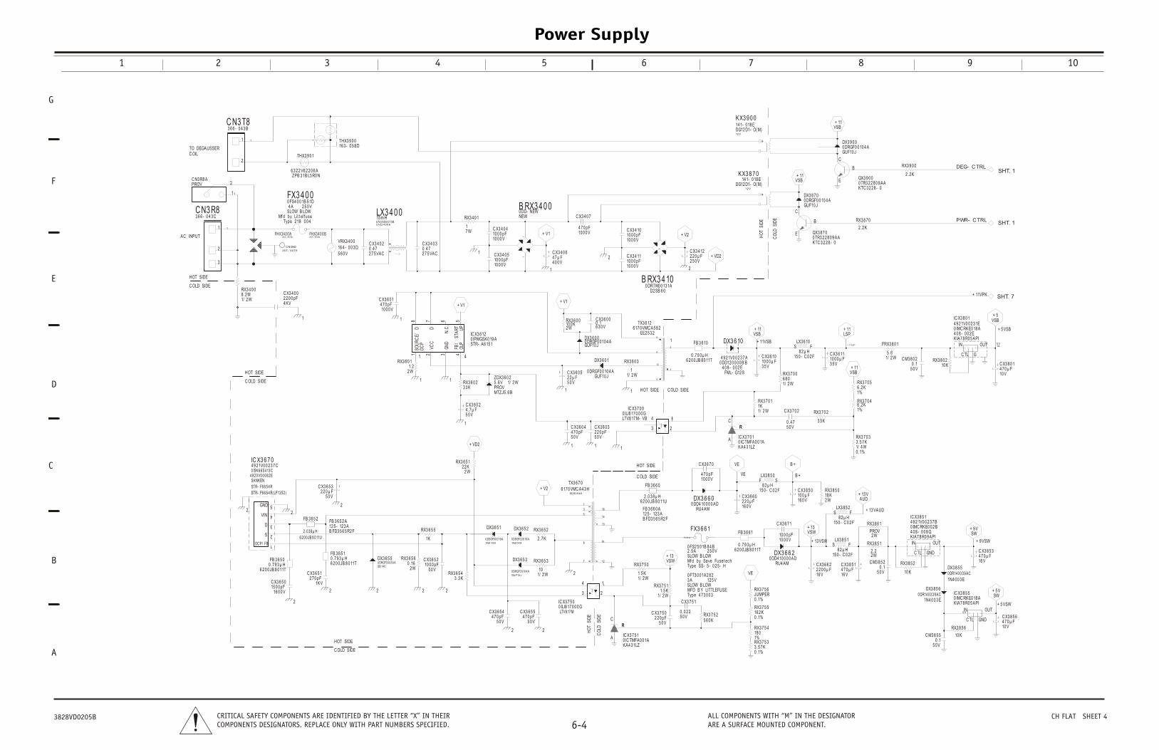
Power Supply
1 2 3 4 5 6 7 8 9 10
G
D
C
B
E
F
A
6-4CRITICAL SAFETY COMPONENTS ARE IDENTIFIED BY THE LETTER “X” IN THEIRCOMPONENTS DESIGNATORS. REPLACE ONLY WITH PART NUMBERS SPECIFIED.
ALL COMPONENTS WITH “M” IN THE DESIGNATORARE A SURFACE MOUNTED COMPONENT.
3828VD0205B CH FLAT SHEET 4
+ 9 VSW
SW+ 9 V
+ 5 VSW
SW+ 5 V
+ 13 VAUD
AUD+ 13 V
+ 13 VSW
+ 13VSW
RX3 7 0 2
3 3 K
RX3 7 0 4
1%6 .2 K
RX3 7 0 3
0 .1%1/ 4 W3 .5 7 K
C X3 6 6 2
16 V2 2 0 0 µ F
IC X3 8 5 1
KIA7 8 R0 9 API
GND
OUTIN
C TL
0 IMC RKE0 0 2 B4 0 8 - 0 0 8 Q
4 9 2 1V0 0 2 3 7 B
IC X3 8 5 5
KIA7 8 R0 5 API
GND
OUT5 VIN
C TL
0 IMC RKE0 18 A
RX3 8 6 1
2 WPROV
RX3 8 5 2
10 K
RX3 8 5 6
10 K
S FLX3 8 5 1
15 0 - C 0 2 F8 2 µ H
S FLX3 8 5 2
15 0 - C 0 2 F8 2 µ H
C X3 8 5 1
16 V4 7 0 µ F
C X3 8 5 6
10 V4 7 0 µ F
C X3 8 5 3
16 V4 7 0 µ F
C M3 8 5 2
5 0 V0 .1
C M3 8 5 5
5 0 V0 .1
RX3 8 5 0
2 W18 K
3 8 5 0
Vµ F
RX3 8 5 1
2 W2 .2
DX3 8 5 5
1N4 0 0 3 E0 DR14 0 0 3 9 AC
DX3 8 5 6
1N4 0 0 3 E0 DR14 0 0 3 9 AC
B +
B +
VE
VE
VE
RC
A IC X3 7 0 1
KA4 3 1LZ
R
0 IC TMFA0 0 1A
FB 3 6 6 1
6 2 0 0 JB 8 0 11T0 .7 9 3 µ H
RX3 7 0 11K1/ 2 W
C X3 6 7 1
10 0 0 V10 0 0 pF
DX3 6 6 2
RU4 AM0 DD4 10 0 0 0 AD
RX3 7 5 516 2 K0 .1%RX3 7 5 2
5 6 0 K
RX3 7 5 6JUMPER0 .1%
6 6 1
12 5 VLOW
7 3 0 0 3Y LITTLEFUSE
1A2 8 2
3 6 6 0
4 AM10 0 0 0 AD
X3 6 7 0
10 0 0 V4 7 0 pF
C X3 6 6 0
16 0 V2 2 0 µ F
C X3 7 0 2
5 0 V0 .4 7
SFLX3 8 5 0
15 0 - C 0 2 F8 2 µ H
C X
16 010 0
S- 5 - 0 2 5 - H
2 5 0 VLOWSave Fuset ech
1B 8 4 B
RX3 7 5 418 01%RX3 7 5 33 .5 7 K0 .1%
+ V2
2 2
2
+ VD211 1
1
2
RC
A IC0 IK
R
RX3 6 5 1
2 W2 2 K
RX3 6 0 23 3 K
C X3 6 0 2
5 0 V4 .7 µ F
C X3 6 0 4
5 0 V4 7 0 pF
C X3 6 0 3
5 0 V2 2 0 pF
X3 6 5 5
1K
C X3 6 5 2
5 0 V10 0 0 pF
DX3 6 5 1
0 DSGF0 0 0 19 A1N4 14 8
DX3 6 5 2
0 DSGF0 0 0 19 A1N4 14 8
RX3 6 5 2
2 .7 K
DX3 6 5 3
0 DRGF0 0 10 4 AGUF10 J
C X3 6 5 54 7 0 pF
5 0 V
12
14
7
8
13
5
3
1
9
16
TX3 6 7 0
1
EER3 9 4 0
6 17 0 VMC A4 3 H
3
4 1
2
IC X3 7 5 00 ILI8 17 0 0 0 GLTV8 17 M
1
C X3 6 5 44 7 0 pF
5 0 V
RX3 6 5 43 .3 K
RX3 6 5 3
101/ 2 W
LT0 I
MTZJ5 .6 B
1/ 2 W5 .6 VPROV
CO
LD S
IDE
HO
T SI
DE
2
2
2
22
22
FB 3 6 5 2
6 2 0 0 JB 8 0 11U
2 .0 3 8 µ H
FB 3 6 5 0
6 2 0 0 JB 8 0 11T0 .7 9 3 µ H
FB 3 6 5 1
6 2 0 0 JB 8 0 11T0 .7 9 3 µ H
R
RX3 6 5 6
2 W0 .16
C X3 6 5 0
16 0 0 V15 0 0 pF
FB 3 6 5 2 A
B FD3 5 6 5 R2 F12 5 - 12 3 A
5
4
3
1
2
IC X3 6 7 0
STR- F6 6 5 4 R( LF13 5 2 )
OC P/ FB
GND
VIN
0 ISK6 6 5 4 13 C4 9 2 0 V0 0 0 8 2 E
D
S
4 9 2 1V0 0 2 3 7 C
C X3 6 5 1
1KV2 7 0 pF
C X3 6 5 3
5 0 V2 2 0 µ F
DX3 6 5 5
SB 14 00 DRGF0 0 0 6 9 A
STR- F6 6 5 4 R
SANKEN
C OLD SIDE
HOT SIDE
C OLD SIDE
+ 13VSW
X3 7 5 1C TMFA0 0 1AA4 3 1LZ
RX3 7 5 11.5 K
1/ 2 W
RX3 7 5 0
1.5 K1/ 2 W
FX3
3 ASLOW B
Type 4MFD B
0 FT3 0 0
FB 3 6 6 0
6 2 0 0 JB 8 0 11U2 .0 3 8 µ H
FB 3 6 6 0 A
B FD3 5 6 5 R2 F12 5 - 12 3 A
DX
RU0 DD4
C
3
4 1
2
IC X3 7 0 0
V8 17 M- VB 1LI8 17 0 0 0 G
FX3 6 6 1A
Type S
2 .5 ASLOW BMfd by
0 FS2 5 0
C X3 7 5 1
5 0 V0 .0 2 2C X3 7 5 0
5 0 V2 2 0 pF
HOT SIDE
C OLD SIDE
2
+ V1
C X3 4 0 6
4 0 0 V4 7 µ F
RX3 6 0 0
2 W10 0 K
C X3 4 0 7
10 0 0 V4 7 0 pF
C X3 6 0 0
6 3 0 V0 .1
DX3 6 0 0
GUF10 J0 DRGF0 0 10 4 A
1%6 .2 K
PWR- C TRL
DEG- C TRL
+ 11VPK
+ 11LSP
+ 11SP
VSB+ 11
+ 5 VSB
+ 5VSB
QX3 9 0 0
B
KTC 3 2 2 8 - 00 TR3 2 2 8 0 9 AA
RX3 7 0 5
RX3 8 0 210 K
C M3 8 0 2
5 0 V0 .1
RX3 8 7 0
2 .2 K
X3 9 0 0
UF10 JDRGF0 0 10 4 A
RX3 9 0 0
2 .2 K
IC X3 8 0 1
KIA7 8 R0 5 API
0 IMC RKE0 18 A4 0 8 - 0 0 2 E
IN OUT
G
5 V1A
C TL
4 9 2 1V0 0 2 3 1E
C X3 8 0 1
10 V4 7 0 µ F
FRX3 8 0 1
1/ 2 W5 .6
L
+ V2
2
+ VD2
VSB+ 11
VSB+ 11
+ 11VSB
+ 11VSB
B RX3 4 10D2 SB 6 0
~~
0 DRTW0 0 13 1A
QX3 8 7 0E
B
C
KTC 3 2 2 8 - 00 TR3 2 2 8 0 9 AA
E
C
C X3 4 12
2 5 0 V2 2 0 µ F
RX3 6 0 3C X3 6 1010 0 0 µ F
C X3 6 11
3 5 V10 0 0 µ F
DX3 6 10
4 9 2 1V0 0 2 3 7 A0 DD12 0 0 0 0 B B
2
10
8
6
TX3 6 12
1
EE2 5 3 26 17 0 VMC A5 8 2
KX3 9 0 0
12 V
DG12 D1- O( M)14 1- 0 18 E
D
G0
KX3 8 7 0
12 V
DG12 D1- O( M)14 1- 0 18 E
DX3 8 7 00 DRGF0 0 10 4 AGUF10 J
C X3 4 10
10 0 0 V10 0 0 pF
C X3 4 11
10 0 0 V10 0 0 pF
S FLX3 6 10
15 0 - C 0 2 F8 2 µ H
DX3 6 0 1
FB 3 6 10
6 2 0 0 JB 8 0 11T0 .7 9 3 µ H
HO
T SI
DE
CO
LD S
IDE
1
C X3 6 0 5
5 0 V2 2 µ F GUF10 J
0 DRGF0 0 10 4 A
1
1/ 2 W1
3 5 V
RX3 7 0 0
1/ 2 W6 8 0
FML- G12 S4 0 8 - 0 0 2 E4
9
C OLD SIDEHOT SIDE
1
+ V1
1
+ V1
1
B RX3 4 0 0NEW0 DD- NEW
~
~
RX3 4 0 1
7 W1
5678
4321
N.C
.
SOU
RC
E/ STA
RT
UP
OLP
D
FB/
VCC
OC
PD
GN
D
IC X3 6 12
STR- A6 15 10 IPMGSK0 19 A
LX3 4 0 0LFZ2 4 V0 66 14 0 VB 0 0 13 B15 m H
C X3 6 0 1
10 0 0 V4 7 0 pF
C X3 4 0 2
2 7 5 VAC0 .4 7
C X3 4 0 3
2 7 5 VAC0 .4 7
C X3 4 0 4
10 0 0 V10 0 0 pF
C X3 4 0 5
10 0 0 V10 0 0 pF
1
4
ZDX3 6 0 21
RX3 6 0 1
2 W1.2
1
HOT SIDE
1
RX3 4 0 0
1/ 2 W8 .2 M
FX3 4 0 0
Type 2 18 0 0 4
2 5 0 V4 ASLOW B LOW
Mfd by Lit t elf use
0 FS4 0 0 1B 5 1D
C NGND
3 8 7 - 9 0 7 E
THX3 9 0 1
6 3 2 2 V6 2 2 0 6 AZPB 3 1B L5 R0 N
1
2
C N3 T8
1
3 6 6 - 0 4 3 B
1
2
3
C N3 R8
1
3 6 6 - 0 4 3 C
1
2C N3 R8 A
1
PROV
VRX3 4 0 0
5 6 0 V16 4 - 0 0 3 D
FHX3 4 0 0 A4 3 1- 8 13 A
FHX3 4 0 0 B4 3 1- 8 13 A
C X3 4 0 0
4 KV2 2 0 0 pF
THX3 9 0 01
16 3 - 0 5 8 DTO DEGAUSSERC OIL
AC INPUT
HOT SIDE
C OLD SIDE
SHT. 7
SHT. 1
SHT. 1
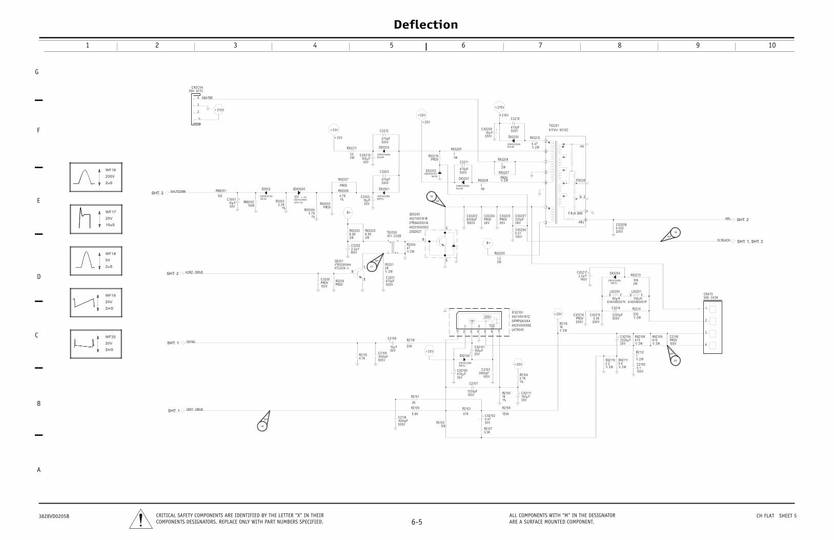
Deflection
1 2 3 4 5 6 7 8 9 10
G
D
C
B
E
F
A
6-5CRITICAL SAFETY COMPONENTS ARE IDENTIFIED BY THE LETTER “X” IN THEIRCOMPONENTS DESIGNATORS. REPLACE ONLY WITH PART NUMBERS SPECIFIED.
ALL COMPONENTS WITH “M” IN THE DESIGNATORARE A SURFACE MOUNTED COMPONENT.
3828VD0205B CH FLAT SHEET 5
FLYB AC K
VSYNC
VERT- DRIVE
SHUTDOWN
AB L
HORZ- DRIVE
B +
+ 2 5 V
+ 2 5 V + 2 15 V
+ 2 15 V
+ 2 5 V
+ 3 3 V
+ 3 3 V
+ 2 15 V
B +
RX3 2 0 2
2 W8 .2 K
RX3 2 0 3
2 W8 .2 K
C 2 10 7
10 0 V12 0 0 pF
C X3 2 0 9
3 5 0 V10 µ F
C 3 0 0 2
5 0 V10 µ F
RX3 0 0 5PROV
RX3 2 0 9
1W1
RX3 2 0 7
1/ 2 WPROV
C 3 2 10
5 0 0 V4 7 0 pF
R3 2 0 4
1/ 2 W4 7
C X3 2 0 8
2 0 0 V0 .0 2 2
DX3 2 0 0
RU2 JGF0 DR2 0 0 0 0 9 DA
DX3 2 0 1
RU2 JGF0 DR2 0 0 0 0 9 DA
RX3 2 11
2 W3 3
R3 2 0 0PROV
RX3 2 12
1/ 2 W0 .4 7
C 3 2 11
5 0 0 V4 7 0 pF
C 3 2 0 2
16 0 V2 .2 µ F
R2 10 1
3 K
ZDX3 0 0 0
GDZJ12 B
1/ 2 W12 V0 DZ12 0 0 0 9 B G
C 2 10 8
5 0 V10 µ F
DX3 2 0 2
1N4 14 80 DSGF0 0 0 19 A
R3 2 0 1
1/ 2 W2 K
1
8
6
9
5
2
11
3
7
AB L
F.B LK.GND
G- 2
HV
FOC US
TX3 2 0 16 17 4 V- 6 0 13 C
C X3 2 0 3
16 0 0 V8 2 0 0 pF
C 3 2 0 0
10 0 VPROV
C X3 2 0 6
10 0 V0 .0 1
C 2 116
5 0 0 V10 0 0 pF
C X3 2 0 5
2 KVPROV
C 3 2 0 1
5 0 0 V4 7 0 pF
C X3 2 0 4
2 KVPROV
RX3 2 0 5
2 W1.2
1 4
2 3
TX3 2 0 0
1
15 1- C 0 2 B
DX2 10 0
RGP15 J0 DR15 0 0 0 9 EA
RX3 2 10PROV
C 3 2 12
5 0 0 V4 7 0 pF
DX3 2 0 3
RU2 JGF0 DR2 0 0 0 0 9 DA
C X2 10 0
3 5 V4 7 0 µ F
C 3 0 0 3
5 0 0 V4 7 0 pF
RX3 0 0 4
1%4 .7 K
C X3 2 13
5 0 V10 0 µ F
DX3 0 0 1
RGP15 J0 DR15 0 0 0 9 EA
RX3 0 0 7
PROV
RX3 0 0 6
1%4 .7 K
RM3 0 0 210 0 K
R3 0 0 3
1%2 .2 K
D3 0 0 2
1N4 14 80 DSGF0 0 0 19 A
C 3 0 0 1
5 0 V10 µ F
RM3 0 0 1
10 0
R2 1154 .7 K
C 2 10 9
5 0 0 V10 0 0 pF
C3 9 0
R2 116
2 0 K
R2 10 3
4 7 K
C X2 10
3 5 V10 0 µ F
R2 10 212 K
R2 10 0
6 .8 K
PUMPUP
4321
GN
D
VCC
1
Q3 2 0 1
E
BCKTC 3 2 2 8 - 0
0 TR3 2 2 8 0 9 AA
HEATER4
3
2
1
C N2 C 5 A
1
3 6 6 - 9 2 1C
QX3 2 0 0
2 SD2 6 2 7
0 TRSA0 0 0 0 1A4 9 2 0 V0 0 0 5 6 C
E
B
C
4 9 2 1V0 0 16 1B
RX3 2 0 6
1W1
+ 2 5 V
+ 2 5 V
RX2 10 9
1/ 2 W4 7 0
R2 114
1/ 2 W1K
R3 2 14
1/ 2 W3 3 0
C 2 10 6
10 0 VPROV
C X3 2 15
2 0 0 V0 .3 6
S FLX3 2 0 0
6 0 µ H6 14 0 VE0 0 0 1V
R2 112
1/ 2 W1
R2 10 44 .7 K1%
C 3 2 14
5 0 0 V2 2 0 0 pF
S FLX3 2 0 1
13 0 µ H6 14 0 VB 0 0 0 1F
R2 10 73 .3 K
RX2 10 8
1/ 2 W4 7 0
RX2 111
1/ 2 W5 .6
RX2 110
1/ 2 W2 .2
R2 10 51K1%
C X2 10 4
2 5 V2 2 0 0 µ F
C 2 10 5
10 0 V0 .12 10 3
10 0 V0 pF
R2 10 6
15 0 K
C X2 111
3 5 V10 0 µ F
1
C X2 10 2
5 0 V0 .4 7
OUTPUT
VC C
THERMALPROTEC T
5 76
STAGE
IC X2 10 0
LA7 8 0 4 0
0 IPRPSA0 0 6 A4 9 2 0 V0 0 0 5 8 E
4 9 2 1V0 0 16 1C
4
3
2
1
C N3 Y33 6 6 - 0 4 3 K
1
C X3 2 16
2 0 0 VPROV
RX3 2 13
2 W10 K
DX3 2 0 4
RGP15 J0 DR15 0 0 0 9 EA
C X3 2 17
16 0 V2 .2 µ F
RX3 2 0 8
2 W1
C X3 2 0 7
2 KV2 2 0 pF
SHT. 1
SHT. 2
SHT. 1
SHT. 2
SHT. 1, SHT. 2
SHT. 2
WF
16
WF
71
WF
18
WF
19
WF
20
200V
2uS
WF16
20V
10uS
WF17
5V
2uS
WF18
20V
2mS
WF19
20V
2mS
WF20
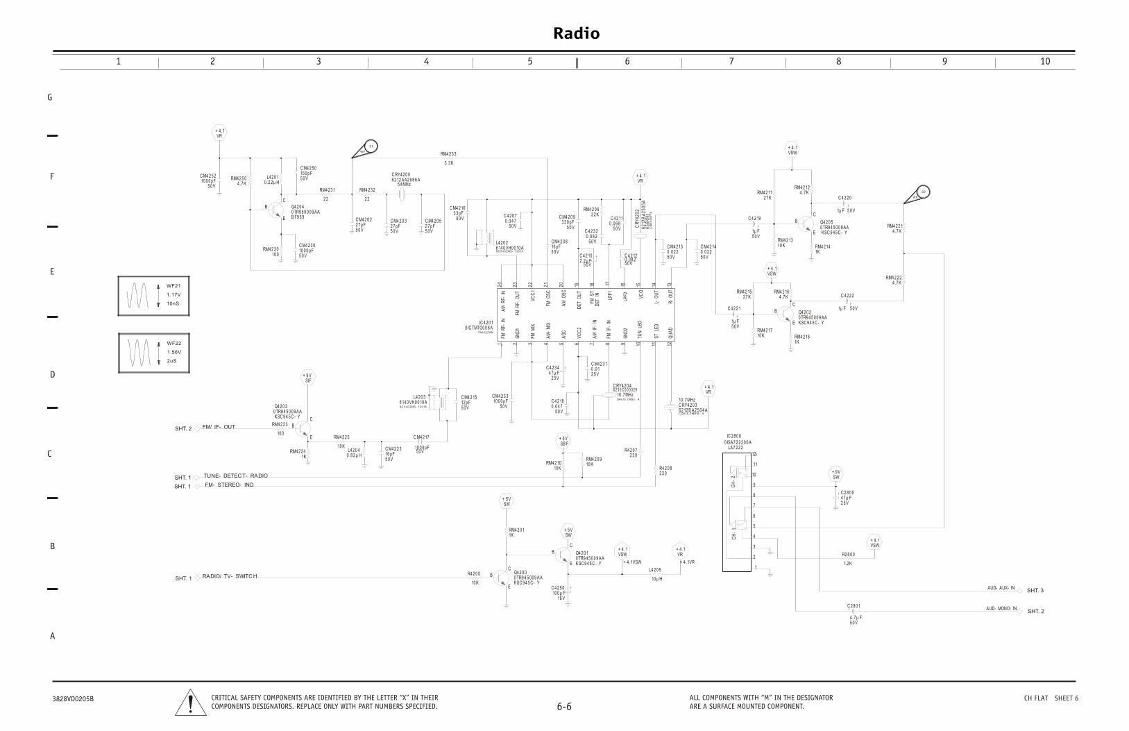
Radio
1 2 3 4 5 6 7 8 9 10
G
D
C
B
E
F
A
6-6CRITICAL SAFETY COMPONENTS ARE IDENTIFIED BY THE LETTER “X” IN THEIRCOMPONENTS DESIGNATORS. REPLACE ONLY WITH PART NUMBERS SPECIFIED.
ALL COMPONENTS WITH “M” IN THE DESIGNATORARE A SURFACE MOUNTED COMPONENT.
3828VD0205B CH FLAT SHEET 6
AUD- AUX- IN
AUD- MONO- IN
VSW+ 4 .1
SW+ 9 V
CH
-1
CH
-2
12
11
10
9
8
7
6
5
4
3
2
1
IC 2 8 0 0
LA7 2 2 21
0 ISA7 2 2 2 0 0 A
C 2 8 0 1
5 0 V4 .7 µ F
R2 8 0 0
1.2 K
C 2 8 0 0
2 5 V4 7 µ F
VR+ 4 .1
+ 5 VSW
+ 5 VSW
+ 4 .1VSW
VSW+ 4 .1
+ 4 .1VR
+ 4 .1VR
+ 5 VSB F
3 3
0 VpF
C 4 2 3 4
2 5 V4 7 µ F
C M4 2 3 1
2 5 V0 .0 1
RM4 2 1010 K R4 2 0 8
2 2 0
R4 2 0 72 2 0
RM4 2 0 910 K
C 4 2 18
5 0 V0 .0 4 7
C RY4 2 0 46 2 0 0 C 0 0 0 0 2 9
SFE10 .7 MS3 - A
10 .7 MHz
C 4 2 5 0
16 V10 0 µ F
L4 2 0 5
10 µ H
RM4 2 0 11K
C RY4 2 0 36 2 12 B A2 5 0 4 AC DA10 .7 MG16 - A
10 .7 MHz
Q4 2 0 0
E
C
0 TR9 4 5 0 0 9 AAKSC 9 4 5 C - Y
Q4 2 0 1
E
BC
0 TR9 4 5 0 0 9 AAKSC 9 4 5 C - Y
FM/ IF- OUT
TUNE- DETEC T- RADIO
RADIO/ TV- SWITC H
FM- STEREO- IND
+ 9 VSIF
L4 2 0 40 .8 2 µ H
RM4 2 2 3
10 0
RM4 2 2 41K
RM4 2 2 5
10 K C M4 2 2 3
5 0 V16 pF
C M4 2 15
5 0 V12 pF
C M4 2 17
5 0 V10 0 0 pF
C M4 2
510 0 0
R4 2 0 0
10 K
L4 2 0 36 14 0 VH0 0 10 ASC 5 4 0 ZNS- 13 0 18
B
Q4 2 0 3
E
BC
0 TR9 4 5 0 0 9 AAKSC 9 4 5 C - Y
VSW+ 4 .1
VSW+ 4 .1
RM4 2 2 24 .7 K
RM4 2 141K
RM4 2 1310 K
RM4 2 2 14 .7 K
C 4 2 19
5 0 V1µ F
RM4 2 112 7 K
RM4 2 124 .7 K
C 4 2 2 0
5 0 V1µ F
C 4 2 2 2
5 0 V1µ F
RM4 2 164 .7 K
RM4 2 152 7 K
RM4 2 1710 K RM4 2 18
1K
C 4 2 2 1
5 0 V1µ F
Q4 2 0 2
E
BC
0 TR9 4 5 0 0 9 AAKSC 9 4 5 C - Y
Q4 2 0 5
E
BC
0 TR9 4 5 0 0 9 AAKSC 9 4 5 C - Y
VR+ 4 .1
L4 2 0 26 14 0 VH0 0 10 ASC 5 4 0 ZNS- 13 0 18
C 4 2 0 7
5 0 V0 .0 4 7
C M4 2 14
5 0 V0 .0 2 2
C 4 2 11
5 0 V0 .0 6 8
C 4 2 12
5 0 V0 .0 8 2
C 4 2 3 2
5 0 V0 .0 8 2
CR
Y420
262
12B
A25
05A
CS
B4
56
F1
645
6KH
z
C M4 2 13
5 0 V0 .0 2 2
RM4 2 0 62 2 K
C 4 2 10
5 0 V2 .2 µ F
C M4 2 0 9
5 0 V3 3 0 pF
C M4 2 0 8
5 0 V16 pF
1 2 3 4 5 6 7 8 9 10 11 12
24 23 22 21 20 19 18 17 16 15 1314
FM R
F-IN
VCO
QU
AD
ST L
ED
TUN
LED
L-O
UT
FM R
F-O
UT
LPF2
AM
OSC
GN
D2
FM I
F-IN
AM
IF-
IN
R-
OU
T
FM O
SC
VCC
2D
ET O
UT
LPF1
AG
C
DET
IN
AM
-M
IX
FM S
T
FM M
IXVC
C1
GN
D1
AM
RF-
IN
1
VR+ 4 .1
RM4 2 3 3
3 .3 K
C M4 2 16
5 0 V3 3 pF
RM4 2 3 2
2 2
RM4 2 3 1
2 2
RM4 2 3 010 0
RM4 2 5 04 .7 K
C M4 2 0 2
5 0 V2 7 pF
C M4 2 0 3
5 0 V2 7 pF
C M4 2 0 5
5 0 V2 7 pF
C M4 2 3 0
5 0 V10 0 0 pF
C M4 2 5 0
5 0 V15 0 pFC M4 2 5 2
5 0 V10 0 0 pF
C RY4 2 0 06 2 12 AA2 9 8 6 A
5 4 MHz
L4 2 0 10 .2 2 µ H
Q4 2 0 4
E
BC
0 TR9 5 9 0 0 9 AAB F9 5 9
IC 4 2 0 10 IC TMTO0 0 6 A
TA8 12 2 AN
SHT. 1
SHT. 2
SHT. 1
SHT. 1
SHT. 3
SHT. 2
WF
21
WF
22
1.17V
10nS
WF21
1.56V
2uS
WF22
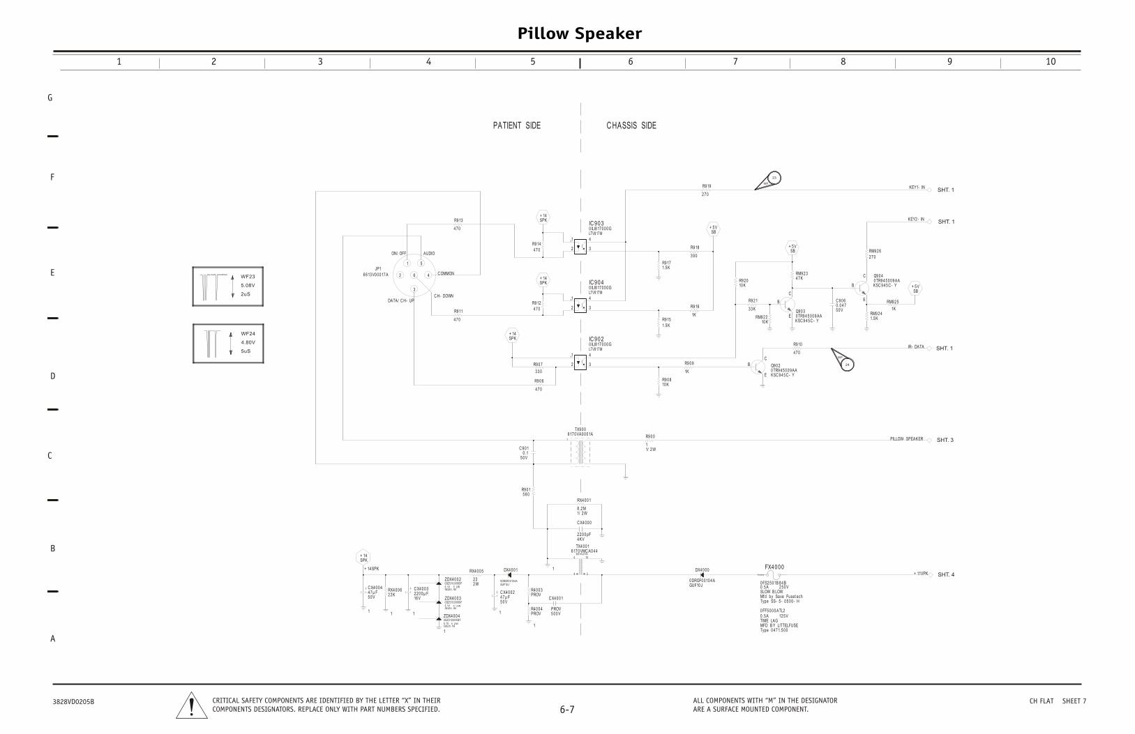
1
11
1
1
1
1
+ 14 SPK
+ 14SPK
RX4 0 0 62 2 K
RX4 0 0 5
2 W2 2
C X4 0 0 2
5 0 V4 7 µ F
ZDX4 0 0 2
1/ 2 W0 DZ5 10 0 0 9 B F
GDZ5 .1B5 .1V
ZDX4 0 0 3
1/ 2 W
0 DZ5 10 0 0 9 B F
GDZ5 .1B5 .1V
ZDX4 0 0 4
1/ 2 W
0 DZ5 10 0 0 9 B F
GDZ5 .1B5 .1V
DX4 0 0 1
GUF10 J0 DRGF0 0 10 4 A
5
104
1
TX4 0 0 1
1
6 17 0 VMC A0 4 4EE16 2 5 S
C X4 0 0 4
5 0 V4 7 µ F
RX4 0 0 1
1/ 2 W8 .2 M
R4 0 0 3PROV
C X4 0 0 0
4 KV2 2 0 0 pF
R9 0 15 6 0
R4 0 0 4PROV
C X4 0 0 1
5 0 0 VPROV
C 9 0 1
5 0 V0 .1
C X4 0 0 3
16 V2 2 0 0 µ F
TX9 0 0
1
6 17 0 VA0 0 0 1A
+ 11VPK
PILLOW- SPEAKER
DX4 0 0 0
GUF10 J0 DRGF0 0 10 4 A
R9 0 0
1/ 2 W1
FX4 0 0 0
Type 0 4 7 1.5 0 0
12 5 V0 .5 ATIME LAGMFD B Y LITTELFUSE
0 FF5 0 0 0 ATL2
FX4 0 0 0 A
Type SS- 5 - 0 5 0 0 - H
2 5 0 V0 .5 ASLOW B LOWMfd by Save Fuset ech
0 FS2 5 0 1B 8 4 B
+ 14SPK
+ 14SPK
+ 14SPK
R9 0 6
4 7 0
3
41
2
IC 9 0 20 ILI8 17 0 0 0 GLTV8 17 M
1
R9 0 7
3 3 0
R9 11
4 7 0
3
41
2
IC 9 0 30 ILI8 17 0 0 0 GLTV8 17 M
1
3
41
2
IC 9 0 40 ILI8 17 0 0 0 GLTV8 17 M
1
R9 144 7 0
R9 124 7 0
R9 13
4 7 0
ON/ OFF
DATA/ C H- UP
C OMMON
AUDIO
C H- DOWN
5
4
1
3
62
JP16 6 13 V0 0 0 17 A
PATIENT SIDE C HASSIS S
KEY1- IN
IR- DATA
KEY2 - IN
+ 5 VSB
+ 5 VSB
+ 5 VSB
Q9 0 2
E
BC
KSC 9 4 5 C - Y0 TR9 4 5 0 0 9 AA
Q9 0 3E
B
C
KSC 9 4 5 C - Y0 TR9 4 5 0 0 9 AA
Q9 0 4
E
B
C
KSC 9 4 5 C - Y0 TR9 4 5 0 0 9 AA
RM9 2 62 7 0
C 9 0 6
5 0 V0 .0 4 7
RM9 2 34 7 K
R9 18
3 9 0
R9 2 1
3 3 K
R9 19
2 7 0
R9 151.5 K
R9 16
1K RM9 2 210 K
R9 171.5 K
R9 0 810 K
R9 0 9
1K
R9 10
4 7 0
R9 2 010 K
RM9 2 41.5 K
RM9 2 5
1K
IDE
SHT. 1
SHT. 1
SHT. 1
SHT. 3
SHT. 4
WF
24
WF
23
5.08V
2uS
WF23
4.80V
5uS
WF24
Pillow Speaker
1 2 3 4 5 6 7 8 9 10
G
D
C
B
E
F
A
6-7CRITICAL SAFETY COMPONENTS ARE IDENTIFIED BY THE LETTER “X” IN THEIRCOMPONENTS DESIGNATORS. REPLACE ONLY WITH PART NUMBERS SPECIFIED.
ALL COMPONENTS WITH “M” IN THE DESIGNATORARE A SURFACE MOUNTED COMPONENT.
3828VD0205B CH FLAT SHEET 7
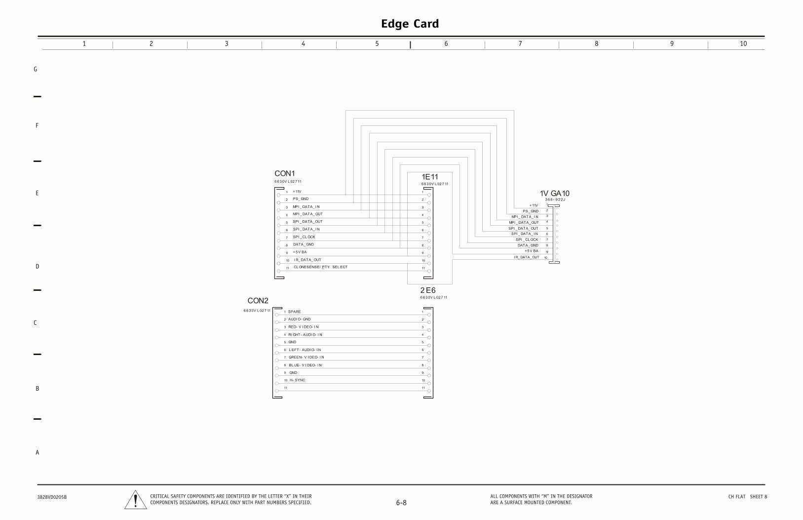
6 6 3 0V L 02 7 11
3 6 6 - 9 2 2 J
CON16 6 3 0V L 02 7 11
1E11
6 6 3 0V L 02 7 11
2 E6
6 6 3 0V L 02 7 11
CON2
1V GA10
4
3
2
1
6
5
7
8
9
10
11
4
3
2
1
6
5
7
8
9
10
11
4
3
2
1
6
5
7
8
9
10
11
4
3
2
1
6
5
7
8
9
10
11
4
3
2
1
5
7
6
10
9
8
H- SYNC
BL UE- V I DEO- I N
GREEN- V I DEO- I N
AUDI O- GND
+11V
+11V
_CL ONESENSE/ PTY SEL ECT
SPARE
MPI _ DATA_ I N
MPI _ DATA_ I N
SPI _ CL OCKSPI _ CL OCK
SPI _ DATA_ I N
SPI _ DATA_ I N
SPI _ DATA_ OUT
SPI _ DATA_ OUT
L EFT- AUDI O- I N
DATA_ GND DATA_ GND
I R_ DATA_ OUTI R_ DATA_ OUT
GND
GND
MPI _ DATA_ OUT
MPI _ DATA_ OUT
PS_ GND
PS_ GND
+5 V BA +5 V BA
RI GHT- AUDI O- I N
RED- V I DEO- I N
Edge Card
1 2 3 4 5 6 7 8 9 10
G
D
C
B
E
F
A
6-8CRITICAL SAFETY COMPONENTS ARE IDENTIFIED BY THE LETTER “X” IN THEIRCOMPONENTS DESIGNATORS. REPLACE ONLY WITH PART NUMBERS SPECIFIED.
ALL COMPONENTS WITH “M” IN THE DESIGNATORARE A SURFACE MOUNTED COMPONENT.
3828VD0205B CH FLAT SHEET 8
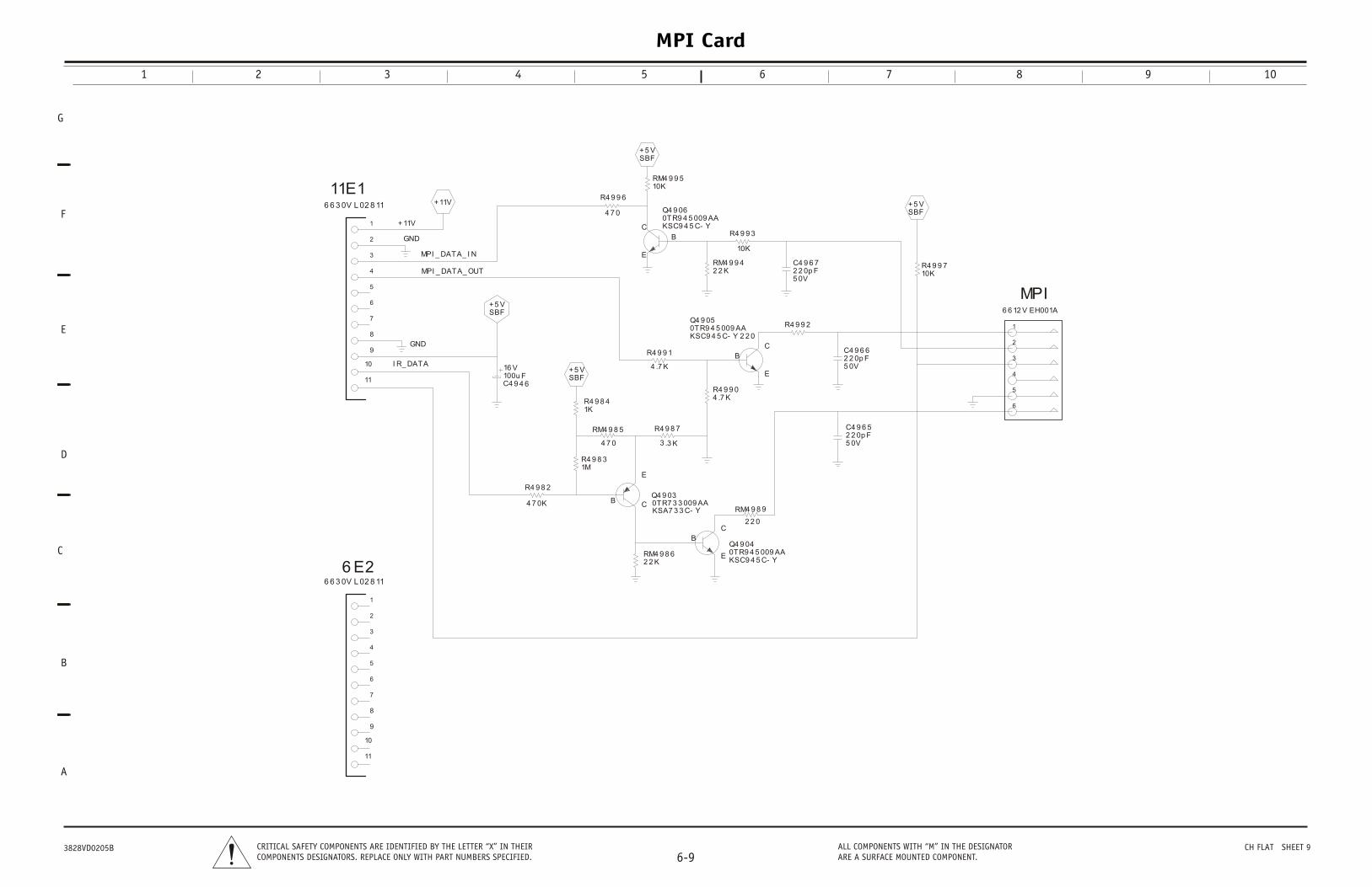
6 6 3 0V L 02 8 11
6 6 3 0V L 02 8 11
2 2 K
2 2 0p F5 0V
10K
4 .7 K
4 .7 K+5 VSBF
1M
+5 VSBF
+5 VSBF
6 6 12 V EH001A
+11V
4 7 0
4 7 0
2 2 K
3 .3 K
1K
2 2 0
4 7 0K
0TR9 4 5 009 AAKSC9 4 5 C- Y
Q4 9 06
10KR4 9 9 7
11E1
RM4 9 8 6
C4 9 6 5
2 2 0p F5 0V
C4 9 6 6
2 2 0p F5 0V
C4 9 6 7
R4 9 9 3
10KRM4 9 9 5
R4 9 9 2
6 E20TR9 4 5 009 AAKSC9 4 5 C- Y
Q4 9 04
R4 9 9 0
R4 9 9 1
0TR9 4 5 009 AA2 2 0KSC9 4 5 C- Y
Q4 9 05
R4 9 8 3
100u F16 V
C4 9 4 6
MPI
R4 9 9 6
RM4 9 8 5
RM4 9 9 4
R4 9 8 4
R4 9 8 2
C
B
E
4
3
2
1
7
6
5
8
9
10
11
CB
E
4
3
2
1
7
6
5
8
9
10
11
C
B
E
C
B
E 4
3
2
1
6
5
+11V
GND
GND
MPI _ DATA_ OUT
I R_ DATA
MPI _ DATA_ I N
+5 VSBF
RM4 9 8 90TR7 3 3 009 AAKSA7 3 3 C- Y
Q4 9 03
MPI Card
1 2 3 4 5 6 7 8 9 10
G
D
C
B
E
F
A
6-9CRITICAL SAFETY COMPONENTS ARE IDENTIFIED BY THE LETTER “X” IN THEIRCOMPONENTS DESIGNATORS. REPLACE ONLY WITH PART NUMBERS SPECIFIED.
ALL COMPONENTS WITH “M” IN THE DESIGNATORARE A SURFACE MOUNTED COMPONENT.
3828VD0205B CH FLAT SHEET 9
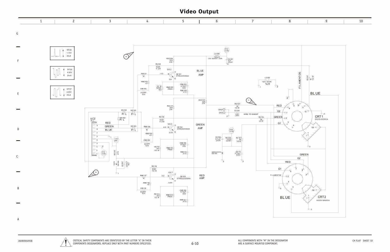
Video Output
1 2 3 4 5 6 7 8 9 10
G
D
C
B
E
F
A
6-10CRITICAL SAFETY COMPONENTS ARE IDENTIFIED BY THE LETTER “X” IN THEIRCOMPONENTS DESIGNATORS. REPLACE ONLY WITH PART NUMBERS SPECIFIED.
ALL COMPONENTS WITH “M” IN THE DESIGNATORARE A SURFACE MOUNTED COMPONENT.
3828VD0205B CH FLAT SHEET 10
WIRE TO SWEEP
BL UE
AMP
GREEN
AMP
REDAMP
3 .6
4 .0
12 8 .2
12 8 .5
4 .0
3 .6 5
12 6 .7
4 .0
3 .6 9
6 6 2 0V BA003 A
6 6 2 0V BC003 A
2 0- 03 9 07 - 2 5A
12 5 - 02 2 K
BL UE
GREEN
RED
P/ L
1
1K 1/2
W
P/ L
1
2
22
0u
F16
V
12 0u H
5 0V2 2 0PF
1K
P/ L
4 7
1
1
2
2
2
1K
1K
2
3.6
V
P/ L
1/2 W15 0K
+9 VSW
2
1/2 W1K
1/2 W1K
1/ 2 W15 0K
1/ 2 W15 0K
1
P/ L4
70
2 15V DC
2 15V DC
2
2
1u H
CV D2 15
5 0V2 2 0PF
5 0V2 2 0PF
2
2 KV0.01
2
W5 103
CRT2
R5
107
W5 104
CRT1
3 5 0V1u FC5 101
1/2 W1K
R5 12 7
1/2 W
15 0R5105
4 .7 u F2 5 0V
C5 108
C5
107
L 5 100
CM5 102
RM5 101
W5 100
RM5 102
1/2 W15 0
R5 12 0
0TR3 2 2 9 00AAQ5 103
RM5 117
RM5 108
PROVRM5 12 0
PROVRM5 112
PROVRM5 105
4 7 0RM5 12 1
4 7 0RM5 113
4 7 0RM5 106
4 7RM5 109
1/2 W2 2 0K
R5 12 6
5 C2
R5 119
5 0V4 7 0p F
CM5 109
12 K2 W
RX5 12 2
12 K2 W
RX5 111
12 K2 W
RX5 104
R5 12 3
R5 115
DAG1
R5 103
4 7 0p F5 0V
CM5 106
R5 110
47RM5 118
0TR3 2 2 9 00AAQ5 101
W5 102
R5
114
DAG
4 7 0p F5 00V
C5 111
L 5 102
5 0V4 7 0p F
CM5 103
CM5 118
0DR14 004 9 AD5 100
0TR3 2 2 9 00AAQ5 102
CM5 105
2
C5 104
1/2 W15 0
R5 112
CB
E
4
3
2
1
7
6
5
8
9
CB
E
CB
E
G2
1
4
5
6
78
9
3
G2
1
4
5
6
7
8
9 1011
12
GREEN
GREEN
G2
G2
G1
G1
BL UE
BL UE
FI L AMENTOS
FIL
AM
EN
TO
S
RED
RED
D5
105
WF
25
WF
26
WF
27
4.60V
20uS
WF26
4.60V
20uS
WF27
1.73V
20uS
WF25
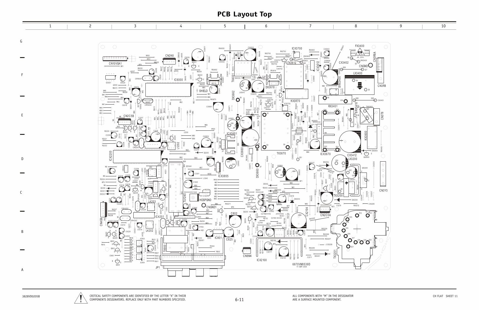
RX3213
QX3 9 0 0
EBC
CX3
209
W82
G9
2 17
CX3
207
R3 2 14
QX3 2 0 0
E
B
C
DX3 2 0 4
TX32
01
RX3 2 0 8
C32
00
CX3
204
C N3 Y3
R32
00
2 0 6
RX3 2 0 9
3205
DX3 2 0 0
Q32
01
E
B
C
RX3
40
C N2 C 5 A1
CX3
205
C X3 2 0 6
C X3 4 12
TX3 2 0 0
CX3
203
R22
27
RX3 2 0 7
C X3 2 0 8
RX3
203
RX3
202
W7 2
C 3 2 0 2
R32
04
DX3 2 0 1
CX3
216
DX3
202
RX3 2 12C 3 2 10
IC X3 6 7 0DX3 9 0 0
G8
E11E12
E13
E14
E15
E16
E17E18 E19 E2 0
C32
14
C32
01
R32
01
E2 1
G10LX3 2 0 0
LX3 2 0 1
G11
G12
G13
L120
5
W9
C RY4 2 0 2
Q9 0 2
E BC
W16
C42
32
C42
11
R9 10
W4
L120
7
W13
Q42
04
E
B
C
R9 19
C30
01
R9 16
W3
W14
R22
49
Q42
03 E
B
C
IC 9 0 4
1
C90
1
R9 15
L420
5
C42
18
IC90
2
1
C 4 2 2 2
L120
3U12 0 1
C 4 2 2 0
C RY4 2 0 3
CN
4G9
TX90
0
JP1
W28
Q42
02
E
B
C
C12
16
CR
Y420
4
W1
Q22
06 EB
C
Q9 0 4E
BC
C 4 2 19
W10
D2 2 0 1
W8
Q4 2 0 5E
B
C
L4 2 0 2
R22
55
D2 2 0 2
R9 2 1
R9 2 0R9 0 8
R9 0 9
U12 0 2
IC 9 0 3
1
C22
21
C 2 2 2 0
R4 2 0 8
CR
2201
C 4 2 10
L220
1
C42
07
CR
Y420
0L4
201
L1204
C 2 2 18
C 4 2 2 1
C 4 2 12
C 2 2 2 5
L420
4
C 2 2 19
R4 2 0 7
C 12 2 2
L4 2 0 3
IC 4 2 0 1
C 2 2 16
Q2 2 0 5EB
C
ICX2
20
Q12
01
E
B
C
W2
D2 2 0 0
R9 17
L2 2 0 0C 2 2 2 7
Q12 0 2
E
B
C
C 12 14
L120
6
W7
C 4 2 3 4
W11
W15
C 2 2 2 6
R9 18
Q42
01
R2 2 2 4
W7 0
Q9 0 3
E BC
C 9 0 6
R9 11
R9 13
R9 14
R9 12
R9 0 7
R9 0 6
CX4
004
W12
IC 8 0 1
R4 2 0 0
W2 4Q
800
E
B
C
C81
6
R80
0
1
W2 5
R28
00
W8 7
W8 8
W8 9
W9 0
W9 1
W2 7
W2 3
W9 2
W10
9 W2 1
W9 3
TU12
40
C 4 2 5 0
W8 4
W7 9
W34 ZD12 4 0
R29
01
L12 4 0
W33
C 12 4 0
C X3 8 5 6
W2 9
W85
W3 6R
2902
E
B
C
W3 5
C 2 8 0 0
W20
R9 0 1
C 12 4 1
W10 5
C 8 0 0
R9 0 0
R14 0 4
C 8 2 5
C80
1 C 8 0 2
C82
4
C2
80
1
ZD2 9 0 1
C 12 4 7
W12 5 0
IC 2 8 0 0
C 14 0 2
D2 2 0 5
W3 7
C NGND1
C 12 4 9
W10 8
IC X3 8 5 5
GN
DO
UT
IN
C TL
Q42
00
E
BC
RX3
856
HOSPGNDRX3 2 11
DX
W3 1
W3 0 W3 8
C12
46
LX38
52G18
G19
R2 2 2 1
W43
C1
C60
98
W7 6
IC60
02G
ND
OU
TVC
C
C60
06
W6 0 0 2
R22
17
W17
0
C 2 2 0 9
C22
06
W5 1
C21
10
W5
C 12 0 6
W18
C 2 2 0 1C
2202
C22
03
C 12 0 7
R2 2 2 2 C22
08
L120
1W19
C R2 2 0 0
Q2 2 0 2
E
BC
R2 2 2 0
U12 0 0C
1212
C 12 10
R12
09
R6 0 3 0
L6 0 0 7
R12
04
R60
27
R60
26
W4 2
R60
41
W55
C N2 C 5 B
1
W10 0
C RY6 0 0 2
W54
R60
13
R60
43
W4 8
L6 0 0 2
W56
W4 1
W49
W57
W4 0
W4 5
W2 2
W3 9
Q22
01
E
B
C
W6
C 6 0 13
W50
R6 0 9 9
W4 6
W10 1
R60
11
L6 0 0 3
R6 0 7 2
W4 7
C 6 0 16
D60
01
C 6 0 2 0IC 6 0 0 1
W86
Q22
00
E
B
C
C N10 VGA1
C RY6 0 0 1
N2 K6
CX4
001
W10 4
RX3
900
R6 0 0 4
D60
02
L12 0 0
C 2 2 3 9
L120
2
SHIELD
L600
1
RX3 8 7 0
W5 2
W58
W44
R60
16
R60
15
L6 0 0 4
W53
Q12
00
E
B
C
L600
5
C 6 0 3 5
Q6 0 0 1
EBC
ZD60
02
W61
ZDX4
004
DX4
001
W6 7
W6 8
W62
W6 9
R40
04
W65
RX3
852
R6 0 0 8
Q6 0 0 2
EB
C
RX3 8 0 2
RX3
861
IC X3 8
GN
DO
UT
INC
TL
RX4 0 0 5
RX3
851
W63
R40
03
W64
W6 6
C X4 0 0 2
CX3
611
C X3 8 5 1
C X3 8 5 3
IC 6 0 0 0
CX3
671
DX3
662
TX40
01
W5 9
W6 0
CX3
801
FRX3
801
ICX3
801
INOUT G
C TL
DX3
855
3856
R12
25
W3 2
LX3 8 5 1
G16
G1
_ A_ V
_ A_ V
W26
FX4 0 0 00 .5 A
12 5 VDX4 0 0 0
DX3
870
C X3 7 5 1
FB36
61
FX3 6 6 1
3 A12 5 V
ZD
X4
00
3
E8
W10
2
RX4
001
5 1
QX3
870
EB
C
DX3 6 10
AK
KX3 8
TX3 6 121
IC X31
C X3 7 0 2
RX3 7 5 0
RX3 7 0 5
RX3 7 0 4
CX3
662
RX3 7 0 2
RX3 7 5 1
W99
RX3
756
ZD
X4
00
2
RX3
703
3660
CX4
000
RX3 7 0 0
IC X3 7 0 1A
R K
FB36
51
C X3 7 5 0
ICX3
751A
R K
RX3 7 0 1
FB 3
RX3
752
F
FB 3 6 10
RX3
754
IC X3 7 5 01
RX3
755
RX4
006
C X4 0 0 3
RX3
753 RX3
652W
103
E1
RX3
653
DX3
653
E2
E3
1
E4
E5
E6
2 .5 A2 5 0 V
0 .5 A
2 5 0 V
C X3 6 10
CX3
650
LX3 6 10
C
G30
7
G2 0
G2 1
G2 4
_ A_ V
CN
3R8A
KX3
900
RX3 4 0 1
C N3 R8
G6
~~- +
BR
X340
0
~~- +
W95
C NGND
G2
G3
W96W
97
CX3
600
CX3
404
CX3
605
RX3
600
RX36
01
CX3
406
G4
CN
3T8
7 0
CX3
654
RX3 6 0 3
7 0 0
0
CX3
407
FX3 4 0 0
4 A 2 5 0 V
FHX3 4 0 0 AFHX3 4 0 0 B
BR
X341
0
+
~~
-
VRX3 4 0 0
LX3 4 0 0
G5
ICX3
612
CX3
655
W9 4
RX3 6 0 2
C X3 6 0 3
C X3 6 0 4
DX3
601
C X3 6 0 2
6 5 2 A
ZDX3 6 0 2
B 3 6 5 2
CX3
652
RX3 6 5 5DX3
655
CX3
653
RX3
654
CX3
405
OC P/ FB
GN
D
VIN
D
S
FB36
50
CX3
411
DX3
651
DX3
652
CX3
410
RX3
656
G7
E10
E9
G2 7
E3 8 E3 9
G1
E3 2 E3 7
DX3
600
CX3
601
THX3 9 0 0
1
RX3
651
THX3901
X3400
G2 8 G2 9
G2 2
G2 3
G2 5 C X3 4 0 2
C X3 4 0 3
G2 6
R82
4
RX3
210
R2 2 9 1
RX2
110
R21
04
C N9 M4
1
R21
06
C 2 116
ZDX3 0 0 0
Q2 2 0 7E
BC
R21
07
C X3
W10
6
E7
W74
DX3 2 0 3
R2 112
Q2 2 0 3E B
C
W7 8
C21
09
C X3 2 13
R22
40
R2 115
C22
24
RX3
DX3
660
RX
RX3
850
FB36
60A
CX2
104
CX3
670
W10
7
W7 1
C 3 2 12
D2 2 0 3
RX2
108
CX
W8 0
W8 3
R22
39
D22
04
C 2 10 5Q22
04
E
B
C
C 3 2 11
C 3 0 0 2
R2 2 3 2 C22
22
R2 2 9 2
C22
90
R2 2 9 0
W9 8
D3 0 0 2
RX2
109
CX3850
CX3
215
W8 1
C22
23
R3 0 0 3
R2 10 1
DX3 0 0 1
W7 7C 3 0 0 3
RX3 0 0 4
RX3 0 0 5
RX3 0 0 6
FB36
60
RX3 0 0 7
RX2
111
R21
14
R21
05
C X2 111
CX3
651
C 2 10 8
R21
16
CX2
102
W75
R21
03
IC X2 10 0
1R2 10 2
C X2 10 0C21
03
W7 3
DX2 10 0
C 2 10 7
R2 10 0
C 2 10 6
C X2 10 1
TX3 6 7 0
LX3 8 5 0
G14
G15
G3 1
17 / SEP/ 2 0 0 46 8 7 0 VM0 5 3 9 D
PCB Layout Top
1 2 3 4 5 6 7 8 9 10
G
D
C
B
E
F
A
6-11CRITICAL SAFETY COMPONENTS ARE IDENTIFIED BY THE LETTER “X” IN THEIRCOMPONENTS DESIGNATORS. REPLACE ONLY WITH PART NUMBERS SPECIFIED.
ALL COMPONENTS WITH “M” IN THE DESIGNATORARE A SURFACE MOUNTED COMPONENT.
3828VD0205B CH FLAT SHEET 11
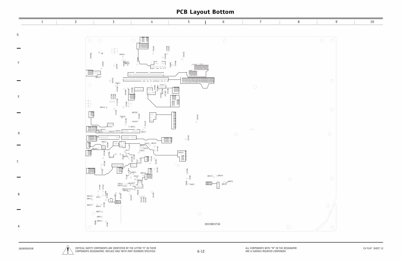
604M60
M60
603604
M60
460004
221220
221
R
RM12 15
RM3 0 0 2 C M12 18
4
CM
RM3 0 0 1C M12 0 1
51
RM2213
40
C M12 0 4
RM2252
RM2229
CM2225
RM2241
CM1242R
M2243 R
M
RM2228
CM2215
RM2225
C M2 2 3 6 RM1223C
RM12 0 6
R
CM1202
RM2245
RM2210
RM1207
RM1201
RM1208
9
CM1205
RM2208
RM1213
2
RM1212
RM1200
RM2214
RM12 10
RM2211
RM12 11
C M2 2 0 0
36
CM1200
RM1231
CM1209
CM1211
RM2 2 16
CM1208
C M2 2 0 5C M2 2 10RM2 113
RM6052
RM6038
RM1205
RM6047
RM6045
C M2 112
RM12 0 2
CM1213
RM1203
RM1214
CM1219
RM1216
CM1221
RM2257
CM1223
RM2242
CM2217
RM2226
RM2223
CM2214
7
CM2213
CM3855
5 9 2
CM1203
CM3852
RM1226
RM12 2 4C M12 2 4
C M2 2 3 4 C M12 17
CM6099
RM RR
RM6069
RM6035
RM6059
CM6080
RM6060
RM6070
RM6061
RM6009
RM
RM R
RM6058
RM4209
RM6 0 3 3RM6080
C M6 0 0 9
CM6037
RM6014
RM6090
RM2206
JM1
RM6001
RM220
CM6003
RM6003
CM6001
RM6005
RM2200
RM6002
RM6006
RM2203
RM2205
RM2201
CM6036
RM4 2 10
RM
RM6049
RM6050
RM6046
CM6021
CM6022
RM6048
CM6002
C M6 0 17
RM6037
RM6010
RM2207
CM3802
CM22
RM
RM
CM6053
CM6043
CM6052
RM
CM6055
CM6095
CM6040
CM6049
CM6097
CM6008
CM6010
CM6042
CM6079
CM6038
CM6090
CM6093
CM6023
CM6094
CM6051
CM6041
CM6091
CM6050
CM6092
CM6011
CM6012
RM6032
CM6005
CM6048
CM6047
CM6019
CM6007
CM6015
CM6056
CM6014
CM6033
CM6025
CM6024
CM6054
CM6058
CM6059
CM6060
CM6018
CM6046
CM6045
RM6 0 3 4
RM2202
RM6031
C M4 2 5 0
M1222
C M4 2 3 1
RM4 2 18
2228
RM1218
CM1220
CM4230
RM4201
RM4250
RM4 2 17
RM4 2 15
CM4214
CM1243
RM4231
CM4203
RM2246
RM4230
RM832
CM4205
RM2247
RM4212
RM2230
RM2231
CM4209
C M4 2 17
RM4 2 2 2
CM4213
RM4 2 2 5
CM2292
C M4 2 2 3
1221
RM4 2 11
C M4 2 0 8
RM821
CM4215
RM4224
RM2248
M2235
M2256
C M4 2 3 3
CM4202
CM2231
CM2291
CM1215
RM4 2 13
RM4214
RM4 2 2 1
RM4233
RM926
RM822
C M8 2 2
RM9 2 2
RM2 2 4 4
RM1219 RM4 2 2 3
RM9 2 5
RM924
RM2253
RM2 2 3 8
CM1245
RM4232
RM9 2 3
RM2 2 3 6
RM2 2 3 5
RM2 2 3 7
RM4216
RM2 2 3 3
RM4206
RM2 2 3 4
RM1217
CM4252
C M4 2 16
CM2237
RM1220
CM1244
6870VM0539D
PCB Layout Bottom
1 2 3 4 5 6 7 8 9 10
G
D
C
B
E
F
A
6-12CRITICAL SAFETY COMPONENTS ARE IDENTIFIED BY THE LETTER “X” IN THEIRCOMPONENTS DESIGNATORS. REPLACE ONLY WITH PART NUMBERS SPECIFIED.
ALL COMPONENTS WITH “M” IN THE DESIGNATORARE A SURFACE MOUNTED COMPONENT.
3828VD0205B CH FLAT SHEET 12
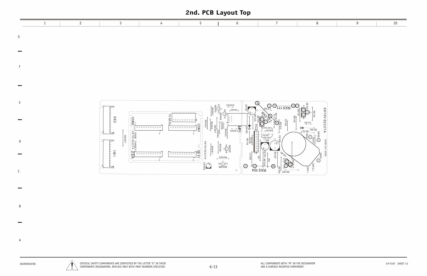
D5100C
510
8
CR
T1
CR
T2
W016 0
C49 6 5
C4
96
6
C4 9 6 7
6E
211E
1
MP
I
R4
99
7
R4
99
2
R4990
R4
99
1
R4
99
6
C5
107
R4
98
7
C5
104
R4
98
3
W3
L5
100
R5
114
Q5
102
Q5
103
C5
101
L5102
D5
105
DA
G
RX5104
RX5111RX512
2
W2
Q4
90
5
Q5 101
W5102
R5
103
R5
115
W2
01
R5
123
R5
119
R5
110
R5127
Q4
90
4
C5 111
W5103
DA
G2
R5
112
R5
126
W2
00
R5105
R5
120
R4
98
4
1VG
A10
CO
N2
2E
6
CO
N1
1E11
W4
R5
107
W5100
W5104
Q4 9 06
5C
2W
1
68
70
VS
22
27
A
68
70
VS
22
27
A
68
70
VS
22
27
A
AU
G/
24
/2
00
4
11
1
EB
C
EB
C
EC
B
E
B
C
EC
B
1
1
EB
C
1
1
1
EC
B
1
ED
GE
T
AR
GE
T
DA
G1
Q4
90
3
R4
99
3
C4
94
6R
49
82
2nd. PCB Layout Top
1 2 3 4 5 6 7 8 9 10
G
D
C
B
E
F
A
6-13CRITICAL SAFETY COMPONENTS ARE IDENTIFIED BY THE LETTER “X” IN THEIRCOMPONENTS DESIGNATORS. REPLACE ONLY WITH PART NUMBERS SPECIFIED.
ALL COMPONENTS WITH “M” IN THE DESIGNATORARE A SURFACE MOUNTED COMPONENT.
3828VD0205B CH FLAT SHEET 13
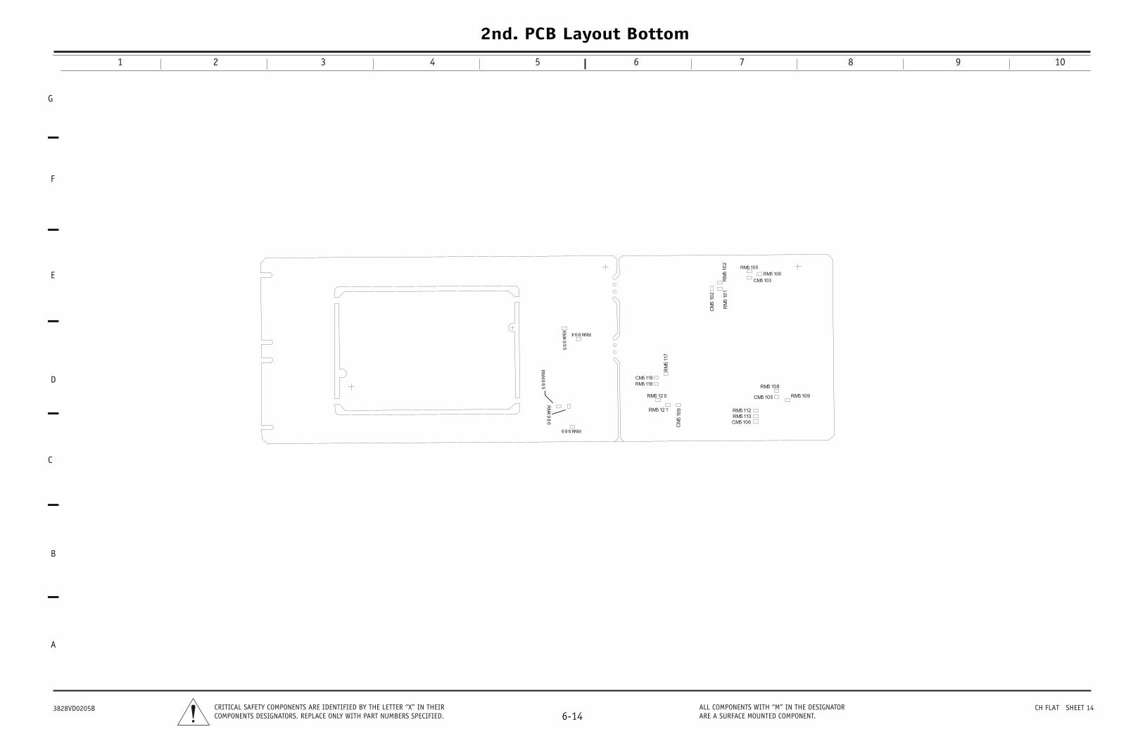
RM4989
RM
49
86
RM
49
95
RM
49
85
RM4994
CM5 105
CM5 118
CM5 103
CM5 106
CM
510
9
CM
510
2
RM5 118
RM5 109
RM5 106
RM5 113
RM5 12 1
RM5 105
RM5 112
RM5 108
RM
511
7
RM
510
2R
M5
101
RM5 12 0
2nd. PCB Layout Bottom
1 2 3 4 5 6 7 8 9 10
G
D
C
B
E
F
A
6-14CRITICAL SAFETY COMPONENTS ARE IDENTIFIED BY THE LETTER “X” IN THEIRCOMPONENTS DESIGNATORS. REPLACE ONLY WITH PART NUMBERS SPECIFIED.
ALL COMPONENTS WITH “M” IN THE DESIGNATORARE A SURFACE MOUNTED COMPONENT.
3828VD0205B CH FLAT SHEET 14