service manual book NISSAN GRAND LIVINA
22
FSU-1 SUSPENSION C D F G H I J K L M SECTION FSU A B FSU N O P CONTENTS FRONT SUSPENSION PRECAUTION .............................................. 2 PRECAUTIONS .................................................. 2 Precaution for Supplemental Restraint System (SRS) "AIR BAG" and "SEAT BELT PRE-TEN- SIONER" .................................................................. 2 Precaution Necessary for Steering Wheel Rota- tion After Battery Disconnect .................................... 2 Precautions for Removing of Battery Terminal ........ 3 Precaution for Procedure without Cowl Top Cover ...... 3 Precautions for Suspension ..................................... 3 PREPARATION ........................................... 4 PREPARATION .................................................. 4 Special Service Tools ............................................... 4 Commercial Service Tools ....................................... 4 SYMPTOM DIAGNOSIS .............................. 5 NOISE, VIBRATION AND HARSHNESS (NVH) TROUBLESHOOTING ............................ 5 NVH Troubleshooting Chart ..................................... 5 PERIODIC MAINTENANCE ......................... 6 FRONT SUSPENSION ASSEMBLY .................. 6 Inspection ................................................................. 6 WHEEL ALIGNMENT ......................................... 7 Inspection ................................................................. 7 Adjustment ............................................................... 8 REMOVAL AND INSTALLATION ............... 9 FRONT COIL SPRING AND STRUT ................. 9 Exploded View ......................................................... 9 Removal and Installation ......................................... 9 Disassembly and Assembly ....................................10 Inspection ...............................................................12 Disposal ..................................................................12 TRANSVERSE LINK ......................................... 14 Exploded View ........................................................14 Removal and Installation ........................................14 Inspection ...............................................................14 FRONT STABILIZER ........................................ 16 Exploded View ........................................................16 Removal and Installation ........................................16 Inspection ...............................................................17 FRONT SUSPENSION MEMBER ..................... 18 Exploded View ........................................................18 Removal and Installation ........................................18 Inspection ...............................................................19 SERVICE DATA AND SPECIFICATIONS (SDS) ........................................................... 20 SERVICE DATA AND SPECIFICATIONS (SDS) ................................................................. 20 Wheel Alignment ....................................................20 Ball Joint .................................................................21 Wheelarch Height ...................................................21
description
service manual book NISSAN GRAND LIVINA
Transcript of service manual book NISSAN GRAND LIVINA
SUSPENSION
C
D
SECTION FSUA
B
SU
FFRONT SUSPENSION
F
G
H
I
J
K
L
M
N
O
P
CONTENTS
PRECAUTION ............................................... 2
PRECAUTIONS ................................................... 2Precaution for Supplemental Restraint System (SRS) "AIR BAG" and "SEAT BELT PRE-TEN-SIONER" ...................................................................2Precaution Necessary for Steering Wheel Rota-tion After Battery Disconnect .....................................2Precautions for Removing of Battery Terminal .........3Precaution for Procedure without Cowl Top Cover ......3Precautions for Suspension ......................................3
PREPARATION ............................................ 4
PREPARATION ................................................... 4Special Service Tools ................................................4Commercial Service Tools ........................................4
SYMPTOM DIAGNOSIS ............................... 5
NOISE, VIBRATION AND HARSHNESS (NVH) TROUBLESHOOTING ............................. 5
NVH Troubleshooting Chart ......................................5
PERIODIC MAINTENANCE .......................... 6
FRONT SUSPENSION ASSEMBLY ................... 6Inspection ..................................................................6
WHEEL ALIGNMENT .......................................... 7Inspection ..................................................................7Adjustment ................................................................8
REMOVAL AND INSTALLATION ................ 9
FRONT COIL SPRING AND STRUT ................. 9Exploded View .......................................................... 9Removal and Installation .......................................... 9Disassembly and Assembly .....................................10Inspection ................................................................12Disposal ...................................................................12
TRANSVERSE LINK .........................................14Exploded View .........................................................14Removal and Installation .........................................14Inspection ................................................................14
FRONT STABILIZER ........................................16Exploded View .........................................................16Removal and Installation .........................................16Inspection ................................................................17
FRONT SUSPENSION MEMBER .....................18Exploded View .........................................................18Removal and Installation .........................................18Inspection ................................................................19
SERVICE DATA AND SPECIFICATIONS (SDS) ............................................................20
SERVICE DATA AND SPECIFICATIONS (SDS) .................................................................20
Wheel Alignment .....................................................20Ball Joint ..................................................................21Wheelarch Height ....................................................21
FSU-1

PRECAUTIONS
< PRECAUTION >PRECAUTIONPRECAUTIONS
Precaution for Supplemental Restraint System (SRS) "AIR BAG" and "SEAT BELT PRE-TENSIONER" INFOID:0000000008956718
The Supplemental Restraint System such as “AIR BAG” and “SEAT BELT PRE-TENSIONER”, used alongwith a front seat belt, helps to reduce the risk or severity of injury to the driver and front passenger for certaintypes of collision. Information necessary to service the system safely is included in the “SRS AIR BAG” and“SEAT BELT” of this Service Manual.WARNING:Always observe the following items for preventing accidental activation.• To avoid rendering the SRS inoperative, which could increase the risk of personal injury or death in
the event of a collision that would result in air bag inflation, all maintenance must be performed byan authorized NISSAN/INFINITI dealer.
• Improper maintenance, including incorrect removal and installation of the SRS, can lead to personalinjury caused by unintentional activation of the system. For removal of Spiral Cable and Air BagModule, see “SRS AIR BAG”.
• Never use electrical test equipment on any circuit related to the SRS unless instructed to in this Ser-vice Manual. SRS wiring harnesses can be identified by yellow and/or orange harnesses or harnessconnectors.
PRECAUTIONS WHEN USING POWER TOOLS (AIR OR ELECTRIC) AND HAMMERSWARNING:Always observe the following items for preventing accidental activation.• When working near the Air Bag Diagnosis Sensor Unit or other Air Bag System sensors with the
ignition ON or engine running, never use air or electric power tools or strike near the sensor(s) witha hammer. Heavy vibration could activate the sensor(s) and deploy the air bag(s), possibly causingserious injury.
• When using air or electric power tools or hammers, always switch the ignition OFF, disconnect thebattery, and wait at least 3 minutes before performing any service.
Precaution Necessary for Steering Wheel Rotation After Battery DisconnectINFOID:0000000008956719
CAUTION:Comply with the following cautions to prevent any error and malfunction.• This Procedure is applied only to models with Intelligent Key system and NATS (NISSAN ANTI-
THEFT SYSTEM).• Remove and install all control units after disconnecting both battery cables with the ignition switch
in the LOCK position.• Always use CONSULT to perform self-diagnosis as a part of each function inspection after finishing
work. If DTC is detected, perform trouble diagnosis according to self-diagnostic results.For models equipped with the Intelligent Key system and NATS, an electrically controlled steering lock mech-anism is adopted on the key cylinder.For this reason, if the battery is disconnected or if the battery is discharged, the steering wheel will lock andsteering wheel rotation will become impossible.If steering wheel rotation is required when battery power is interrupted, follow the procedure below beforestarting the repair operation.
OPERATION PROCEDURE1. Connect both battery cables.
NOTE:Supply power using jumper cables if battery is discharged.
2. Use the Intelligent Key or mechanical key to turn the ignition switch to the ACC position. At this time, thesteering lock will be released.
3. Disconnect both battery cables. The steering lock will remain released and the steering wheel can berotated.
4. Perform the necessary repair operation.
FSU-2
PRECAUTIONS
C
D
F
G
H
I
J
K
L
M
A
B
SU
N
O
P
< PRECAUTION >
F
5. When the repair work is completed, return the ignition switch to the LOCK position before connecting thebattery cables. (At this time, the steering lock mechanism will engage.)
6. Perform a self-diagnosis check of all control units using CONSULT.
Precautions for Removing of Battery Terminal INFOID:0000000009889775
• When removing the 12V battery terminal, turn OFF the ignition switch and wait at least 30 seconds.NOTE:ECU may be active for several tens of seconds after the ignition switch is turned OFF. If the battery terminalis removed before ECU stops, then a DTC detection error or ECU data corruption may occur.
• For vehicles with the 2-batteries, be sure to connect the main battery and the sub battery before turning ONthe ignition switch.NOTE:If the ignition switch is turned ON with any one of the terminals of main battery and sub battery discon-nected, then DTC may be detected.
• After installing the 12V battery, always check "Self Diagnosis Result" of all ECUs and erase DTC.NOTE:The removal of 12V battery may cause a DTC detection error.
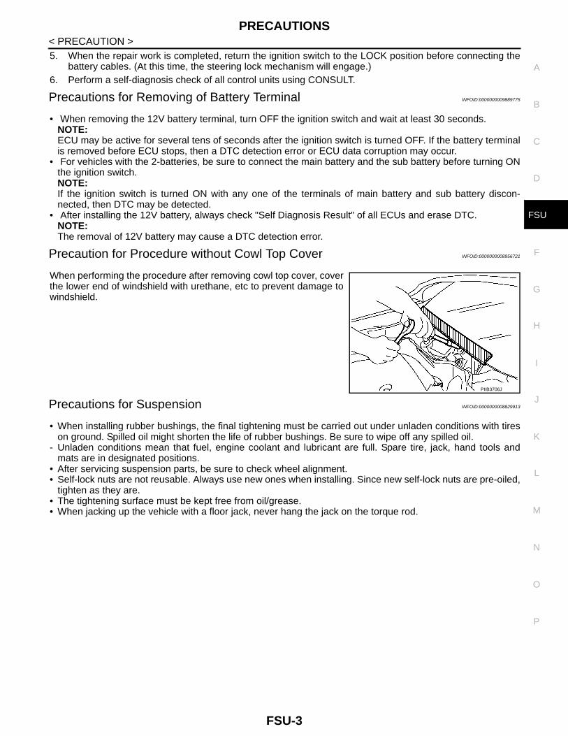
Precaution for Procedure without Cowl Top Cover INFOID:0000000008956721
When performing the procedure after removing cowl top cover, coverthe lower end of windshield with urethane, etc to prevent damage towindshield.
Precautions for Suspension INFOID:0000000008829913
• When installing rubber bushings, the final tightening must be carried out under unladen conditions with tireson ground. Spilled oil might shorten the life of rubber bushings. Be sure to wipe off any spilled oil.
- Unladen conditions mean that fuel, engine coolant and lubricant are full. Spare tire, jack, hand tools andmats are in designated positions.
• After servicing suspension parts, be sure to check wheel alignment.• Self-lock nuts are not reusable. Always use new ones when installing. Since new self-lock nuts are pre-oiled,
tighten as they are. • The tightening surface must be kept free from oil/grease.• When jacking up the vehicle with a floor jack, never hang the jack on the torque rod.
PIIB3706J
FSU-3

PREPARATION
< PREPARATION >PREPARATIONPREPARATION
Special Service Tools INFOID:0000000008829914
Commercial Service Tools INFOID:0000000008829915
Tool numberTool name
Description
KV991040S11. KV99104020 Adapter A2. KV99104030 Adapter B3. KV99104040 Adapter C4. KV99104050 Adapter D5. KV99104060 Plate6. KV99104070 Guide bolt7. KV99104080 Spring8. KV99104090 Center plate
Measuring wheel alignment
ST35652000Strut attachment
Disassembling and assembling strut
ZZA1167D
ZZA0807D
Tool name Description
Spring compressor Removing and installing coil spring
S-NT717
FSU-4

NOISE, VIBRATION AND HARSHNESS (NVH) TROUBLESHOOTING
C
D
F
G
H
I
J
K
L
M
A
B
SU
N
O
P
< SYMPTOM DIAGNOSIS >
F
SYMPTOM DIAGNOSISNOISE, VIBRATION AND HARSHNESS (NVH) TROUBLESHOOTING
NVH Troubleshooting Chart INFOID:0000000008829916
Use chart below to find the cause of the symptom. If necessary, repair or replace these parts.
×: Applicable
Reference
FS
U-9
, FS
U-1
4, F
SU
-16,
FS
U-1
8
FS
U-1
2
— —
FS
U-1
2
FS
U-9
, FS
U-1
4, F
SU
-16,
FS
U-1
8
FS
U-7
FS
U-1
7
NV
H in
FA
X a
nd F
SU
sec
tions
NV
H in
WT
sec
tion
NV
H in
WT
sec
tion
NV
H in
FA
X s
ectio
n
NV
H in
BR
sec
tion
NV
H in
ST
sec
tion
Possible cause and SUSPECTED PARTS
Impr
oper
inst
alla
tion,
loos
enes
s
Sho
ck a
bsor
ber
defo
rmat
ion,
dam
age
or d
efle
ctio
n
Bus
hing
or
mou
ntin
g de
terio
ratio
n
Par
ts in
terf
eren
ce
Spr
ing
fatig
ue
Sus
pens
ion
loos
enes
s
Inco
rrec
t whe
el a
lignm
ent
Sta
biliz
er b
ar fa
tigue
FR
ON
T A
XLE
AN
D F
RO
NT
SU
SP
EN
SIO
N
TIR
E
RO
AD
W
HE
EL
DR
IVE
SH
AF
T
BR
AK
E
ST
EE
RIN
G
Symptom FRONT SUSPENSION
Noise × × × × × × × × × × × ×
Shake × × × × × × × × × × ×
Vibration × × × × × × × × ×
Shimmy × × × × × × × × × ×
Judder × × × × × × × ×
Poor quality ride or handling
× × × × × × × × × ×
FSU-5

FRONT SUSPENSION ASSEMBLY
< PERIODIC MAINTENANCE >PERIODIC MAINTENANCEFRONT SUSPENSION ASSEMBLY
Inspection INFOID:0000000008829917
COMPONENT PARTCheck the mounting conditions (looseness, backlash) of each component and component conditions (wear,damage) are normal.
Ball Joint Axial End Play
1. Set front wheels in a straight-ahead position.2. Hold an axle side of transverse link, and check axial end play by
move it up and down.
CAUTION:• Never depress brake pedal when measuring.• Never perform with tires on level ground.• Be careful not to damage ball joint boot. Never damage
the installation position by applying excessive force.
STRUT ASSEMBLYCheck for oil leakage, damage, and replace if necessary.
Axial end play : Refer to FSU-21, "Ball Joint".
JSEIA0444ZZ
FSU-6

WHEEL ALIGNMENT
C
D
F
G
H
I
J
K
L
M
A
B
SU
N
O
P
< PERIODIC MAINTENANCE >
F
WHEEL ALIGNMENT
Inspection INFOID:0000000008829918
DESCRIPTIONCAUTION:• The adjustment mechanisms of camber, caster, and kingpin inclination angles are not included.• If camber, caster, or kingpin inclination angle is outside the standard, check front suspension parts
for wear and damage. Replace suspect parts if a malfunction is detected.• Kingpin inclination angle is reference value, no inspection is required.Measure wheel alignment under unladen conditions. NOTE:“Unladen conditions” means that fuel, engine coolant, and lubricant are full. Spare tire, jack, hand tools andmats are in designated positions.
PRELIMINARY CHECKCheck the following:• Tires for improper air pressure and wear. Refer to WT-7, "Removal and Installation".• Road wheels for runout.• Wheel bearing axial end play. Refer to FAX-9, "Inspection".• Transverse link ball joint axial end play.• Strut operation.• Each mounting part of axle and suspension for looseness and deformation.• Each of suspension member, strut and transverse link for cracks, deformation and other damage.• Vehicle height (posture).
CAMBER, CASTER, AND KINGPIN INCLINATION ANGLESBefore inspection, mount front wheels onto turning radius gauge. Mount rear wheels onto a stand at the sameheight so that vehicle remains horizontal.
Using a CCK GaugeInstall the CCK gauge attachment (SST: KV991040S1) with the following procedure on wheel, then measurewheel alignment.1. Remove three wheel to nuts, and install the guide bolts to hub
bolt.2. Screw the adapter into the plate until it contacts the plate tightly.3. Screw the center plate into the plate.4. Insert the plate assembly on the guide bolt. Put the spring in,
and then evenly screw the three guide bolt nuts. When fasteningthe guide nuts, do not completely compress the spring.
5. Place the dent of alignment gauge onto the projection of thecenter plate and tightly contact them to measure.
CAUTION:• If camber, caster, or kingpin inclination angle exceeds the
standard value, check front suspension parts for wear anddamage. Replace suspect parts if a malfunction isdetected.
• Kingpin inclination angle is reference value, no inspectionis required.
TOE-INMeasure toe-in by the following procedure.
SEIA0240E
Camber, caster, kingpin inclination angles
: Refer to FSU-20, "Wheel Alignment".
SEIA0241E
FSU-7

WHEEL ALIGNMENT
< PERIODIC MAINTENANCE >WARNING:• Always perform the following procedure on a flat surface.• Check that no person is in front of vehicle before pushing it.1. Bounce front of vehicle up and down to stabilize the vehicle height (posture).2. Push vehicle straight ahead about 5 m (16 ft).3. Put matching mark on base line of the tread (rear side) ofboth tires at the same height of hub center. These are measur-ing points.
4. Measure distance (A) (rear side).
5. Push vehicle slowly ahead to rotate wheels 180 degrees (1/2turn).NOTE:If the wheels rotates more than 180 degrees (1/2 turn), start thisprocedure again from the beginning. Do not push the vehiclebackward.
6. Measure distance (B) (front side).
• If toe-in exceeds the standard value, adjust toe-in by varying the length of between steering outer socketand inner socket. Refer to FSU-8, "Adjustment".
Adjustment INFOID:0000000008829919
TOE-INLoosen the steering outer socket, and then adjust the length using steering inner socket.
CAUTION:• Always evenly adjust both toe-in alternately and adjust the difference between the left and right to
the standard. • Always fix the steering inner socket when tightening the steering outer socket.
JPEIA0014ZZ
: Vehicle front
Total toe-in = A – BTotal toe-in : Refer to FSU-20, "Wheel Alignment".
JPEIA0015ZZ
Toe-in : Refer to FSU-20, "Wheel Alignment".
FSU-8
FRONT COIL SPRING AND STRUT
C
D
F
G
H
I
J
K
L
M
A
B
SU
N
O
P
< REMOVAL AND INSTALLATION >
F
REMOVAL AND INSTALLATIONFRONT COIL SPRING AND STRUT
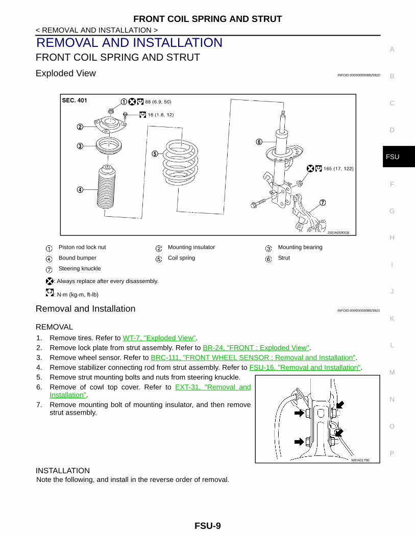
Exploded View INFOID:0000000008829920
Removal and Installation INFOID:0000000008829921
REMOVAL1. Remove tires. Refer to WT-7, "Exploded View".2. Remove lock plate from strut assembly. Refer to BR-24, "FRONT : Exploded View".3. Remove wheel sensor. Refer to BRC-111, "FRONT WHEEL SENSOR : Removal and Installation".4. Remove stabilizer connecting rod from strut assembly. Refer to FSU-16, "Removal and Installation".5. Remove strut mounting bolts and nuts from steering knuckle.6. Remove of cowl top cover. Refer to EXT-31, "Removal and
Installation".7. Remove mounting bolt of mounting insulator, and then remove
strut assembly.
INSTALLATIONNote the following, and install in the reverse order of removal.
Piston rod lock nut Mounting insulator Mounting bearing
Bound bumper Coil spring Strut
Steering knuckle
: Always replace after every disassembly.
: N·m (kg-m, ft-lb)
JSEIA0590GB
WEIA0179E
FSU-9
FRONT COIL SPRING AND STRUT
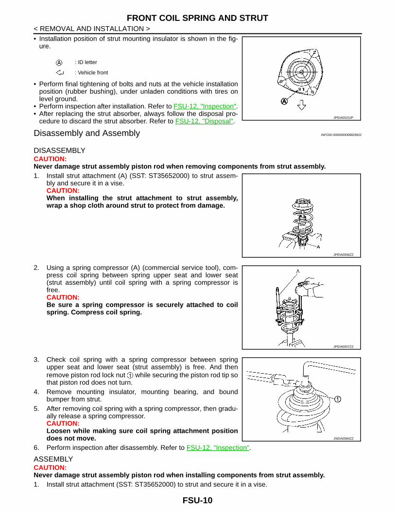
< REMOVAL AND INSTALLATION >• Installation position of strut mounting insulator is shown in the fig-ure.
• Perform final tightening of bolts and nuts at the vehicle installationposition (rubber bushing), under unladen conditions with tires onlevel ground.
• Perform inspection after installation. Refer to FSU-12, "Inspection".• After replacing the strut absorber, always follow the disposal pro-
cedure to discard the strut absorber. Refer to FSU-12, "Disposal".
Disassembly and Assembly INFOID:0000000008829922
DISASSEMBLYCAUTION:Never damage strut assembly piston rod when removing components from strut assembly.1. Install strut attachment (A) (SST: ST35652000) to strut assem-
bly and secure it in a vise.CAUTION:When installing the strut attachment to strut assembly,wrap a shop cloth around strut to protect from damage.
2. Using a spring compressor (A) (commercial service tool), com-press coil spring between spring upper seat and lower seat(strut assembly) until coil spring with a spring compressor isfree.CAUTION:Be sure a spring compressor is securely attached to coilspring. Compress coil spring.
3. Check coil spring with a spring compressor between springupper seat and lower seat (strut assembly) is free. And thenremove piston rod lock nut while securing the piston rod tip sothat piston rod does not turn.
4. Remove mounting insulator, mounting bearing, and boundbumper from strut.
5. After removing coil spring with a spring compressor, then gradu-ally release a spring compressor.CAUTION:Loosen while making sure coil spring attachment positiondoes not move.
6. Perform inspection after disassembly. Refer to FSU-12, "Inspection".
ASSEMBLYCAUTION:Never damage strut assembly piston rod when installing components from strut assembly.1. Install strut attachment (SST: ST35652000) to strut and secure it in a vise.
: ID letter
: Vehicle front
JPEIA0023JP
JPEIA0006ZZ
JPEIA0007ZZ
JSEIA0584ZZ
FSU-10

FRONT COIL SPRING AND STRUT
C
D
F
G
H
I
J
K
L
M
A
B
SU
N
O
P
< REMOVAL AND INSTALLATION >
F
CAUTION:When installing the strut attachment to strut assembly, wrap a shop cloth around strut to protectfrom damage.
2. Compress coil spring using a spring compressor (commercial service tool), and install it onto strut assem-bly.CAUTION:• Install with the small-diameter side (A) facing up and the
large-diameter side (B) facing down.
• Align the lower end of coil spring with of lower seat(strut assembly) as shown in the figure.
• Be sure a compressor is securely attached to coil spring.Compress coil spring.
3. Apply soapy water to bound bumper.CAUTION:Never use machine oil.
4. Set bound bumper to piston rod of strut.5. Install mounting bearing and mounting insulator onto spring.
CAUTION:• Never apply oils, such as grease, when installing the
mounting bearing and mounting insulator.• Installation position of strut mounting insulator is shown
in the figure.
6. Secure piston rod tip so that piston rod does not turn, thentighten piston rod lock nut with specified torque.CAUTION:Never reuse piston rod lock nut.
JSEIA0591ZZ
: ID letter
: Vehicle front
JPEIA0027ZZ
JPEIA0023JP
JSEIA0584ZZ
FSU-11
FRONT COIL SPRING AND STRUT
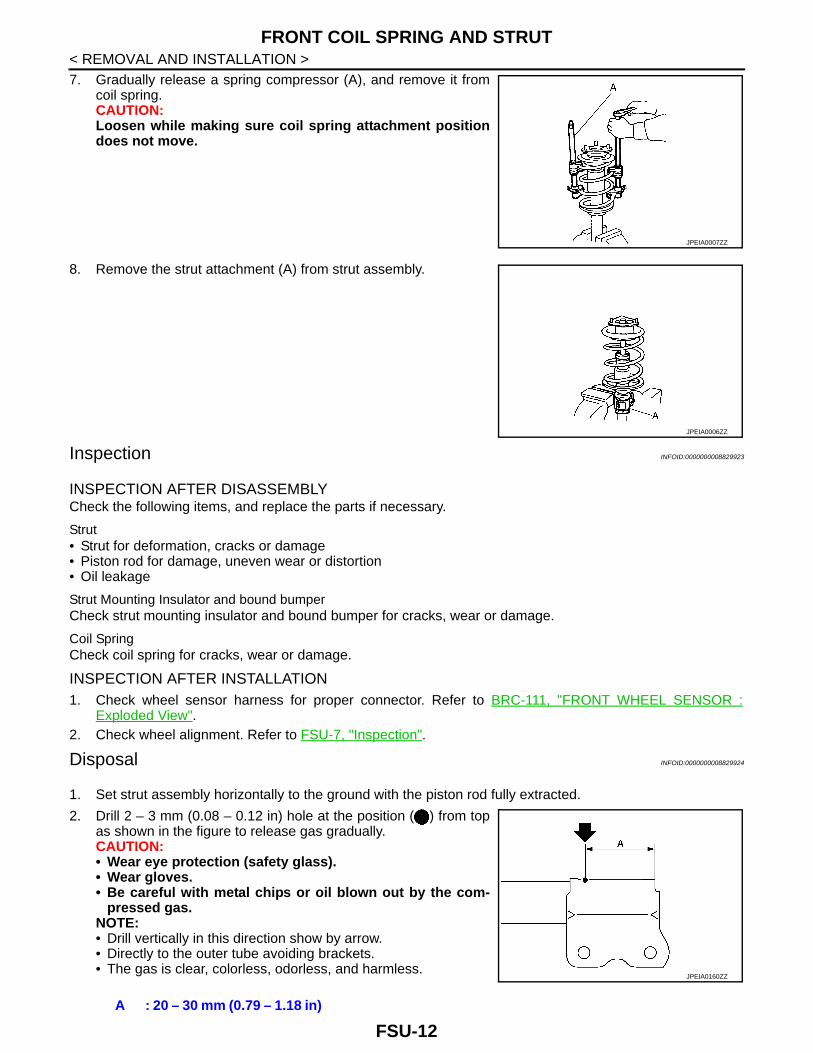
< REMOVAL AND INSTALLATION >7. Gradually release a spring compressor (A), and remove it fromcoil spring.CAUTION:Loosen while making sure coil spring attachment positiondoes not move.
8. Remove the strut attachment (A) from strut assembly.
Inspection INFOID:0000000008829923
INSPECTION AFTER DISASSEMBLYCheck the following items, and replace the parts if necessary.
Strut• Strut for deformation, cracks or damage• Piston rod for damage, uneven wear or distortion• Oil leakage
Strut Mounting Insulator and bound bumperCheck strut mounting insulator and bound bumper for cracks, wear or damage.
Coil SpringCheck coil spring for cracks, wear or damage.
INSPECTION AFTER INSTALLATION1. Check wheel sensor harness for proper connector. Refer to BRC-111, "FRONT WHEEL SENSOR :
Exploded View".2. Check wheel alignment. Refer to FSU-7, "Inspection".
Disposal INFOID:0000000008829924
1. Set strut assembly horizontally to the ground with the piston rod fully extracted.
2. Drill 2 – 3 mm (0.08 – 0.12 in) hole at the position ( ) from topas shown in the figure to release gas gradually.CAUTION:• Wear eye protection (safety glass).• Wear gloves.• Be careful with metal chips or oil blown out by the com-
pressed gas.NOTE:• Drill vertically in this direction show by arrow.• Directly to the outer tube avoiding brackets.• The gas is clear, colorless, odorless, and harmless.
JPEIA0007ZZ
JPEIA0006ZZ
A : 20 – 30 mm (0.79 – 1.18 in)
JPEIA0160ZZ
FSU-12
FRONT COIL SPRING AND STRUT
C
D
F
G
H
I
J
K
L
M
A
B
SU
N
O
P
< REMOVAL AND INSTALLATION >
F
3. Position the drilled hole downward and drain oil by moving the piston rod several times.CAUTION:Dispose of drained oil according to the law and local regulations.
FSU-13

TRANSVERSE LINK
< REMOVAL AND INSTALLATION >TRANSVERSE LINK
Exploded View INFOID:0000000008829925
Removal and Installation INFOID:0000000008829926
REMOVAL1. Remove tires. Refer to WT-7, "Exploded View".2. Remove under cover. Refer to EXT-38, "Exploded View".3. Remove transverse link from steering knuckle. Refer to FAX-11, "Removal and Installation".4. Remove stabilizer connecting rod from strut. Refer to FSU-16, "Removal and Installation".
5. Remove transverse link from suspension member.6. Perform inspection after removal. Refer to FSU-14, "Inspection".
INSTALLATIONNote the following, and install in the reverse order of removal.• Never reuse transverse link mounting bolt and nut.• Perform final tightening of bolts and nuts at the vehicle installation position (rubber bushing), under unladen
conditions with tires on level ground.• Perform inspection after installation. Refer to FSU-14, "Inspection".
Inspection INFOID:0000000008829927
INSPECTION AFTER REMOVALCheck the following items, and replace the parts if necessary.
Upper link Front suspension member Transverse link
: Always replace after every disassembly.
: N·m (kg-m, ft-lb)
JPEIA0199GB
JSEIA0596ZZ
FSU-14

TRANSVERSE LINK
C
D
F
G
H
I
J
K
L
M
A
B
SU
N
O
P
< REMOVAL AND INSTALLATION >
F
Transverse Link• Transverse link and bushing for deformation, cracks or damage.• Ball joint boot for cracks or other damage, and also for grease leakage.
Swing Torque
1. Manually move ball stud to confirm it moves smoothly with no binding.2. Move ball stud at least ten times by hand to check for smooth movement.
3. Hook a spring balance (A) at cutout on ball stud . Confirmspring balance measurement value is within specifications whenball stud begins moving.
• If swing torque exceeds standard range, replace transverse linkassembly.
Axial End Play
1. Move ball stud at least ten times by hand to check for smooth movement.2. Move tip of ball stud in axial direction to check for looseness.
• If axial end play exceeds the standard value, replace transverse link assembly.
INSPECTION AFTER INSTALLATIONCheck wheel alignment. Refer to FSU-7, "Inspection".
Swing torque : Refer to FSU-21, "Ball Joint".Measurement on spring balance
: Refer to FSU-21, "Ball Joint"
JPEIA0138ZZ
Axial end play : Refer to FSU-21, "Ball Joint".
FSU-15

FRONT STABILIZER
< REMOVAL AND INSTALLATION >FRONT STABILIZER
Exploded View INFOID:0000000008829928
LHD models
RHD models
Removal and Installation INFOID:0000000008829929
REMOVAL1. Remove tires. Refer to WT-7, "Exploded View".
JSEIA0592GB
Stabilizer bar Stabilizer clamp Stabilizer bushing
Stabilizer connecting rod Strut assembly Front suspension member
: N·m (kg-m, ft-lb)
JSEIA0741GB
Stabilizer bar Stabilizer clamp Stabilizer bushing
Stabilizer connecting rod Strut assembly Front suspension member
: N·m (kg-m, ft-lb)
FSU-16

FRONT STABILIZER
C
D
F
G
H
I
J
K
L
M
A
B
SU
N
O
P
< REMOVAL AND INSTALLATION >
F
2. Remove stabilizer connecting rod .3. Remove front suspension member. Refer to FSU-18, "Removal
and Installation".
4. Remove mounting bolts ( ) of stabilizer clamp, and thenremove stabilizer clamp and stabilizer bushing from front sus-pension member.
5. Remove stabilizer bar.6. Perform inspection after removal. Refer to FSU-17, "Inspection".
INSTALLATIONNote the following, and install in the reverse order of removal.• Install stabilizer clamp and stabilizer bush with oblong hole and
slit faced forward of the vehicle ( ).
• To install stabilizer connecting rod , tighten the mounting nut withthe hexagonal part on the stabilizer connecting rod side fixed.
• Perform final tightening of bolts and nuts at the vehicle installationposition (rubber bushing), under unladen conditions with tires onlevel ground.
• Perform inspection after installation. Refer to FSU-14, "Inspection".
Inspection INFOID:0000000008829930
INSPECTION AFTER REMOVALCheck stabilizer bar, stabilizer connecting rod, stabilizer bushing and stabilizer clamp for deformation, cracksor damage. Replace it if necessary.
INSPECTION AFTER INSTALLATIONCheck wheel alignment. Refer to FSU-7, "Inspection".
JSEIA0597ZZ
WEIA0182E
JPEIA0194ZZ
JPEIA0252ZZ
FSU-17
FRONT SUSPENSION MEMBER
< REMOVAL AND INSTALLATION >FRONT SUSPENSION MEMBER
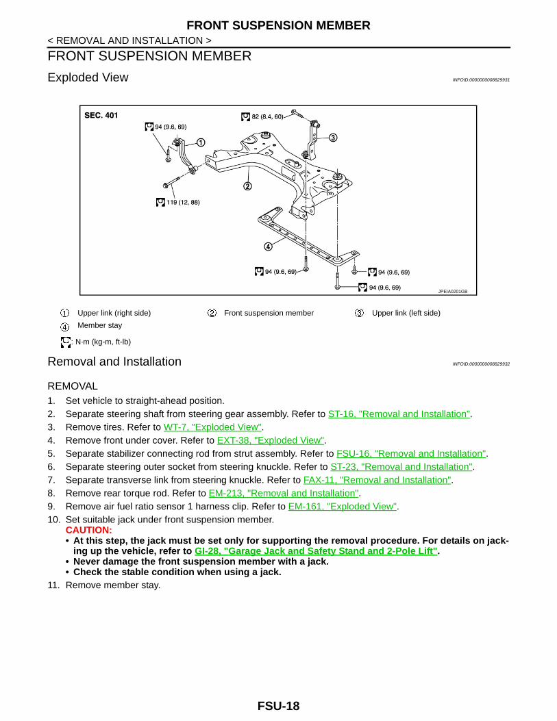
Exploded View INFOID:0000000008829931
Removal and Installation INFOID:0000000008829932
REMOVAL1. Set vehicle to straight-ahead position.2. Separate steering shaft from steering gear assembly. Refer to ST-16, "Removal and Installation".3. Remove tires. Refer to WT-7, "Exploded View".4. Remove front under cover. Refer to EXT-38, "Exploded View".5. Separate stabilizer connecting rod from strut assembly. Refer to FSU-16, "Removal and Installation".6. Separate steering outer socket from steering knuckle. Refer to ST-23, "Removal and Installation".7. Separate transverse link from steering knuckle. Refer to FAX-11, "Removal and Installation".8. Remove rear torque rod. Refer to EM-213, "Removal and Installation".9. Remove air fuel ratio sensor 1 harness clip. Refer to EM-161, "Exploded View".10. Set suitable jack under front suspension member.
CAUTION:• At this step, the jack must be set only for supporting the removal procedure. For details on jack-
ing up the vehicle, refer to GI-28, "Garage Jack and Safety Stand and 2-Pole Lift".• Never damage the front suspension member with a jack.• Check the stable condition when using a jack.
11. Remove member stay.
Upper link (right side) Front suspension member Upper link (left side)
Member stay
: N·m (kg-m, ft-lb)
JPEIA0201GB
FSU-18

FRONT SUSPENSION MEMBER
C
D
F
G
H
I
J
K
L
M
A
B
SU
N
O
P
< REMOVAL AND INSTALLATION >
F
12. Remove upper link (right side) mounting bolt .
13. Remove upper link (left side) mounting bolt .14. Remove suspension member mounting bolts from the vehicle.15. Gradually lower the jack to remove front suspension member
from vehicle body.CAUTION:Check the stable condition when using a jack.NOTE:Remove suspension member with upper link (right side), trans-verse links, stabilizer assembly and steering gear assembly.
16. Remove output speed sensor. Refer to TM-623, "Removal andInstallation". (CVT)
17. Remove upper link (left side) from vehicle body.18. Remove upper link (right side), transverse links, and stabilizer assembly from suspension member.19. Remove air fuel ratio sensor 1 harness bracket. Refer to EM-161, "Exploded View".20. Remove steering gear assembly from front suspension member. Refer to ST-23, "Removal and Installa-
tion".21. Perform inspection after removal. Refer to FSU-14, "Inspection".
INSTALLATIONNote the following, and install in the reverse order of removal.• Perform final tightening of bolts and nuts, under unladen conditions with tires on level ground.• Perform inspection after installation. Refer to FSU-14, "Inspection".
Inspection INFOID:0000000008829933
INSPECTION AFTER REMOVALCheck front suspension member for cracks, wear or damage. Replace it if necessary.
INSPECTION AFTER INSTALLATIONCheck wheel sensor harness for proper connector. Refer to BRC-111, "FRONT WHEEL SENSOR : ExplodedView".
JSEIA0598ZZ
JSEIA0599ZZ
FSU-19
SERVICE DATA AND SPECIFICATIONS (SDS)
< SERVICE DATA AND SPECIFICATIONS (SDS)SERVICE DATA AND SPECIFICATIONS (SDS)SERVICE DATA AND SPECIFICATIONS (SDS)
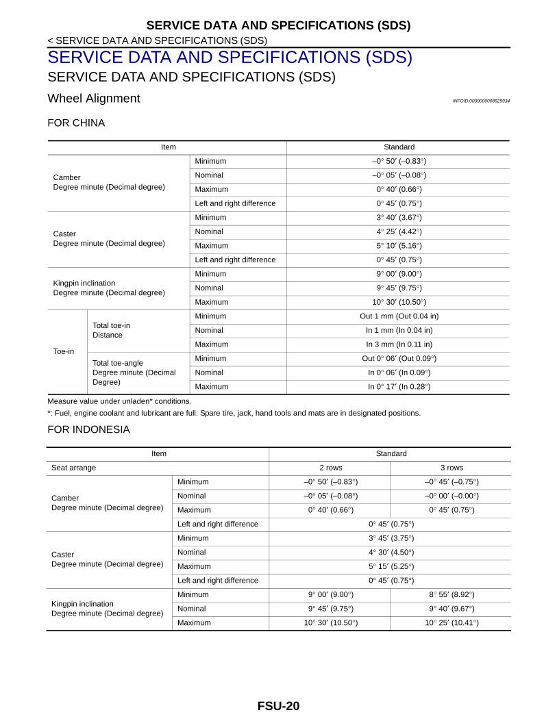
Wheel Alignment INFOID:0000000008829934
FOR CHINA
Measure value under unladen* conditions.
*: Fuel, engine coolant and lubricant are full. Spare tire, jack, hand tools and mats are in designated positions.
FOR INDONESIA
Item Standard
CamberDegree minute (Decimal degree)
Minimum –0° 50′ (–0.83°)
Nominal –0° 05′ (–0.08°)
Maximum 0° 40′ (0.66°)
Left and right difference 0° 45′ (0.75°)
CasterDegree minute (Decimal degree)
Minimum 3° 40′ (3.67°)
Nominal 4° 25′ (4.42°)
Maximum 5° 10′ (5.16°)
Left and right difference 0° 45′ (0.75°)
Kingpin inclinationDegree minute (Decimal degree)
Minimum 9° 00′ (9.00°)
Nominal 9° 45′ (9.75°)
Maximum 10° 30′ (10.50°)
Toe-in
Total toe-inDistance
Minimum Out 1 mm (Out 0.04 in)
Nominal In 1 mm (In 0.04 in)
Maximum In 3 mm (In 0.11 in)
Total toe-angleDegree minute (Decimal Degree)
Minimum Out 0° 06′ (Out 0.09°)
Nominal In 0° 06′ (In 0.09°)
Maximum In 0° 17′ (In 0.28°)
Item Standard
Seat arrange 2 rows 3 rows
CamberDegree minute (Decimal degree)
Minimum –0° 50′ (–0.83°) –0° 45′ (–0.75°)
Nominal –0° 05′ (–0.08°) –0° 00′ (–0.00°)
Maximum 0° 40′ (0.66°) 0° 45′ (0.75°)
Left and right difference 0° 45′ (0.75°)
CasterDegree minute (Decimal degree)
Minimum 3° 45′ (3.75°)
Nominal 4° 30′ (4.50°)
Maximum 5° 15′ (5.25°)
Left and right difference 0° 45′ (0.75°)
Kingpin inclinationDegree minute (Decimal degree)
Minimum 9° 00′ (9.00°) 8° 55′ (8.92°)
Nominal 9° 45′ (9.75°) 9° 40′ (9.67°)
Maximum 10° 30′ (10.50°) 10° 25′ (10.41°)
FSU-20

SERVICE DATA AND SPECIFICATIONS (SDS)
C
D
F
G
H
I
J
K
L
M
A
B
SU
N
O
P
< SERVICE DATA AND SPECIFICATIONS (SDS)
F
Measure value under unladen* conditions.
*: Fuel, engine coolant and lubricant are full. Spare tire, jack, hand tools and mats are in designated positions.
Ball Joint INFOID:0000000008829935
Wheelarch Height INFOID:0000000008829936
FOR CHINA
Measure value under unladen* conditions.
*: Fuel, engine coolant and lubricant are full. Spare tire, jack, hand tools and mats are in designated positions.
FOR INDONESIA
Toe-in
Total toe-inDistance
Minimum Out 1 mm (Out 0.04 in)
Nominal In 1 mm (In 0.04 in)
Maximum In 3 mm (In 0.11 in)
Total toe-angleDegree minute (Decimal Degree)
Minimum Out 0° 06′ (Out 0.09°)
Nominal In 0° 06′ (In 0.09°)
Maximum In 0° 17′ (In 0.28°)
Item Standard
Item Standard
Swing torque 0.5 – 4.9 N·m (0.06 – 0.49 kg-m, 5 – 43 in-lb)
Measurement on spring balance 15.4 – 150.8 N (1.6 – 15.3 kg, 3.5 – 33.8 lb)
Axial end play 0 mm (0 in)
Item Standard
Front (Hf) 686 mm (27.01 in)
Rear (Hr) 689 mm (27.13 in)
WEIA0030E
Item Standard
Seat arrange 2 rows 3 rows
Front (Hf) 687 mm (27.05 in)
FSU-21

SERVICE DATA AND SPECIFICATIONS (SDS)
< SERVICE DATA AND SPECIFICATIONS (SDS)Measure value under unladen* conditions.
*: Fuel, engine coolant and lubricant are full. Spare tire, jack, hand tools and mats are in designated positions.
Rear (Hr) 693 mm (27.28 in)
Item Standard
WEIA0030E
FSU-22