Service Literature XP15 SERIES UNITS
26
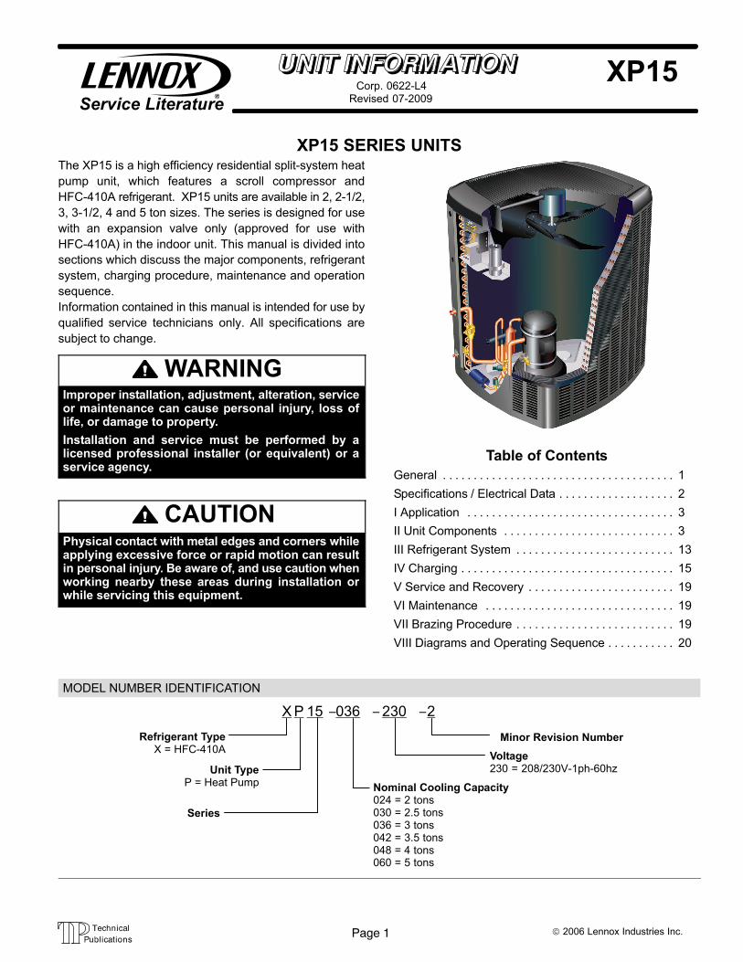
Page 1 © 2006 Lennox Industries Inc. XP15 Service Literature Revised 07−2009 Corp. 0622−L4 XP15 SERIES UNITS The XP15 is a high efficiency residential split−system heat pump unit, which features a scroll compressor and HFC−410A refrigerant. XP15 units are available in 2, 2−1/2, 3, 3−1/2, 4 and 5 ton sizes. The series is designed for use with an expansion valve only (approved for use with HFC−410A) in the indoor unit. This manual is divided into sections which discuss the major components, refrigerant system, charging procedure, maintenance and operation sequence. Information contained in this manual is intended for use by qualified service technicians only. All specifications are subject to change. WARNING Improper installation, adjustment, alteration, service or maintenance can cause personal injury, loss of life, or damage to property. Installation and service must be performed by a licensed professional installer (or equivalent) or a service agency. CAUTION Physical contact with metal edges and corners while applying excessive force or rapid motion can result in personal injury. Be aware of, and use caution when working nearby these areas during installation or while servicing this equipment. Table of Contents General 1 . . . . . . . . . . . . . . . . . . . . . . . . . . . . . . . . . . . . . . Specifications / Electrical Data 2 . . . . . . . . . . . . . . . . . . . I Application 3 . . . . . . . . . . . . . . . . . . . . . . . . . . . . . . . . . . II Unit Components 3 . . . . . . . . . . . . . . . . . . . . . . . . . . . . III Refrigerant System 13 . . . . . . . . . . . . . . . . . . . . . . . . . . IV Charging 15 . . . . . . . . . . . . . . . . . . . . . . . . . . . . . . . . . . . V Service and Recovery 19 . . . . . . . . . . . . . . . . . . . . . . . . VI Maintenance 19 . . . . . . . . . . . . . . . . . . . . . . . . . . . . . . . VII Brazing Procedure 19 . . . . . . . . . . . . . . . . . . . . . . . . . . VIII Diagrams and Operating Sequence 20 . . . . . . . . . . . MODEL NUMBER IDENTIFICATION P 15 036 − − Unit Type P = Heat Pump Series Nominal Cooling Capacity 024 = 2 tons 030 = 2.5 tons 036 = 3 tons 042 = 3.5 tons 048 = 4 tons 060 = 5 tons Minor Revision Number 230 Voltage 230 = 208/230V−1ph−60hz Refrigerant Type X = HFC−410A X 2 −
Transcript of Service Literature XP15 SERIES UNITS
Page 1 © 2006 Lennox Industries Inc.
XP15Service Literature Revised 07−2009
Corp. 0622−L4
XP15 SERIES UNITSThe XP15 is a high efficiency residential split−system heat
pump unit, which features a scroll compressor and
HFC−410A refrigerant. XP15 units are available in 2, 2−1/2,
3, 3−1/2, 4 and 5 ton sizes. The series is designed for use
with an expansion valve only (approved for use with
HFC−410A) in the indoor unit. This manual is divided into
sections which discuss the major components, refrigerant
system, charging procedure, maintenance and operation
sequence.
Information contained in this manual is intended for use by
qualified service technicians only. All specifications are
subject to change.
WARNINGImproper installation, adjustment, alteration, serviceor maintenance can cause personal injury, loss oflife, or damage to property.
Installation and service must be performed by alicensed professional installer (or equivalent) or aservice agency.
CAUTIONPhysical contact with metal edges and corners whileapplying excessive force or rapid motion can resultin personal injury. Be aware of, and use caution whenworking nearby these areas during installation orwhile servicing this equipment.
Table of Contents
General 1. . . . . . . . . . . . . . . . . . . . . . . . . . . . . . . . . . . . . .
Specifications / Electrical Data 2. . . . . . . . . . . . . . . . . . .
I Application 3. . . . . . . . . . . . . . . . . . . . . . . . . . . . . . . . . .
II Unit Components 3. . . . . . . . . . . . . . . . . . . . . . . . . . . .
III Refrigerant System 13. . . . . . . . . . . . . . . . . . . . . . . . . .
IV Charging 15. . . . . . . . . . . . . . . . . . . . . . . . . . . . . . . . . . .
V Service and Recovery 19. . . . . . . . . . . . . . . . . . . . . . . .
VI Maintenance 19. . . . . . . . . . . . . . . . . . . . . . . . . . . . . . .
VII Brazing Procedure 19. . . . . . . . . . . . . . . . . . . . . . . . . .
VIII Diagrams and Operating Sequence 20. . . . . . . . . . .
MODEL NUMBER IDENTIFICATION
P 15 036− −
Unit TypeP = Heat Pump
Series
Nominal Cooling Capacity024 = 2 tons030 = 2.5 tons036 = 3 tons042 = 3.5 tons048 = 4 tons060 = 5 tons
Minor Revision Number
230
Voltage230 = 208/230V−1ph−60hz
Refrigerant TypeX = HFC−410A
X 2−

Page 2XP15 Revised 06−2009
SPECIFICATIONS
GeneralData
Model No. XP15−024 XP15−030 XP15−036 XP15−042 XP15−048 XP15−060
Nominal Tonnage 2 2.5 3 3.5 4 5
Connections(sweat)
Liquid line (o.d.) − in. 3/8 3/8 3/8 3/8 3/8 3/8
Vapor (Suction) line (o.d.) − in. 3/4 3/4 3/4 7/8 7/8 1−1/8
Refrigerant 1 HFC−410A charge furnished 8 lbs. 13 oz. 10 lbs. 11 oz. 11 lbs. 4 oz. 12 lbs. 5 oz. 14 lbs. 14 oz. 15 lbs. 8 oz.
OutdoorCoil
Net face area − sq. ft. Outer coil 20.73 20.73 20.73 20.73 27.21 27.21
Inner coil 20.08 20.08 20.08 20.08 26.36 26.36
Tube diameter − in. 5/16 5/16 5/16 5/16 5/16 5/16
No. of rows 2 2 2 2 2 2
Fins per inch 22 22 22 22 22 22
OutdoorFan
Diameter − in. 26 26 26 26 26 26
No. of blades 3 3 3 3 3 3
Motor hp 1/15 1/15 1/12 1/12 1/5 1/5
Cfm 2100 2100 2300 2300 3910 3910
Rpm 825 825 825 825 825 825
Watts 100 100 112 112 212 212
Shipping Data − lbs. 1 pkg. 290 292 297 323 368 372
ELECTRICAL DATA
Line voltage data − 60hz 208/230V−1ph
2 Maximum overcurrent protection (amps) 30 30 35 40 50 60
3 Minimum circuit ampacity 17.4 18.1 21.5 23.1 28.4 34.1
Compressor Rated load amps 13.5 14.1 16.7 17.9 21.8 26.4
Locked rotor amps 58.3 73.0 79.0 112.0 117.0 134.0
Power factor 0.99 0.97 0.98 0.94 0.99 0.98
Outdoor FanMotor
Full load amps 0.5 0.5 0.65 0.65 1.1 1.1
Locked rotor amps 0.8 0.8 1.1 1.1 2.1 2.1
OPTIONAL ACCESSORIES − must be ordered extra
Compressor Hard Start Kit 88M91 � � � � � �
Compressor Low Ambient Cut−Off 45F08 � � � � � �
Freezestat 3/8 in. tubing 93G35 � � � � � �
5/8 in. tubing 50A93 � � � � � �
Indoor Blower Off Delay Relay 58M81 � � � � � �
Low Ambient Kit 54M89 � � � � � �
Mild Weather Kit 33M07 � � � � � �
Monitor Kit − Service Light 76F53 � � � � � �
OutdoorThermostat Kit
Thermostat 56A87 � � � � � �
Mounting Box 31461 � � � � � �
RefrigerantLine Sets
L15−41−20L15−41−30
L15−41−40L15−41−50
� � �
L15−65−30 L15−65−40L15−65−50
� �
Field Fabricate �
NOTE − Extremes of operating range are plus 10% and minus 5% of line voltage.1 Refrigerant charge sufficient for 15 ft. (4.6 m) length of refrigerant lines.2 HACR type breaker or fuse.3 Refer to National or Canadian Electrical Code manual to determine wire, fuse and disconnect size requirements.

Page 3XP15 Revised 06−2009
CAUTIONTo prevent personal injury, or damage to panels, unitor structure, be sure to observe the following:
While installing or servicing this unit, carefully stowall removed panels out of the way, so that the panelswill not cause injury to personnel, nor cause damageto objects or structures nearby, nor will the panels besubjected to damage (e.g., being bent or scratched).
While handling or stowing the panels, consider anyweather conditions, especially windy conditions,that may cause panels to be blown around and bat-tered.
DANGERShock Hazard
Remove all power at disconnect be-fore removing access panel.XP15 units use single-pole contac-tors. Potential exists for electricalshock resulting in injury or death.Line voltage exists at all components(even when unit is not in operation).
I−APPLICATIONAll major components (indoor blower and coil) must bematched according to Lennox recommendations for thecompressor to be covered under warranty. Refer to the En-gineering Handbook for approved system matchups. Amisapplied system will cause erratic operation and can re-sult in early compressor failure.
II−Unit Components
Removing Access Panels
Remove and reinstall the access panel as described in fig-ure 1.
Remove the louvered panels as follows:
1−. Remove 2 screws, allowing the panel to swing openslightly.
2−. Hold the panel firmly throughout this procedure.Rotate bottom corner of panel away from hinge cornerpost until lower 3 tabs clear the slots (see figure 2, De-tail B).
3−. Move panel down until lip of upper tab clears the topslot in corner post (see figure 2, Detail A).
Remove 4 screws toremove panel foraccessing compressorand controls.
Install by positioningpanel with holesaligned; install screwsand tighten.
FIGURE 1
Access Panel
Position and Install Panel�Position the panel almostparallel with the unit (figure 2, Detail D) with the �screwside" as close to the unit as possible. Then, in a continuousmotion:
� Slightly rotate and guide the LIP of top tab inward (fig-ure 2, Details A and C); then upward into the top slotof the hinge corner post.
� Rotate panel to vertical to fully engage all tabs.
� Holding the panel’s hinged side firmly in place, closethe right−hand side of the panel, aligning the screwholes.
When panel is correctly positioned and aligned, insert thescrews and tighten.

Page 4XP15 Revised 06−2009
Detail A
Detail C
Detail B
FIGURE 2
Removing/Installing Louvered Panels
MAINTAIN MINIMUM PANEL ANGLE (AS CLOSE TO PARALLEL WITH THE UNITAS POSSIBLE) WHILE INSTALLING PANEL.
PREFERRED ANGLEFOR INSTALLATION
Detail D
ROTATE IN THIS DIRECTION;THEN DOWN TO REMOVE PANEL
SCREWHOLES
ANGLE MAY BE TOOEXTREME
HOLD DOOR FIRMLY TO THE HINGED SIDE TO MAINTAIN
FULLY−ENGAGED TABS
LIP
IMPORTANT! Do not allow panels to hang on unit by top tab. Tabis for alignment and not designed to support weight of panel.
Panel shown slightly ro-tated to allow top tab toexit (or enter) top slotfor removing (or instal-ling) panel.
ELECTROSTATIC DISCHARGE (ESD)
Precautions and Procedures
CAUTIONElectrostatic discharge can affect electroniccomponents. Take precautions during unit instal-lation and service to protect the unit’s electroniccontrols. Precautions will help to avoid controlexposure to electrostatic discharge by puttingthe unit, the control and the technician at thesame electrostatic potential. Neutralize electro-static charge by touching hand and all tools on anunpainted unit surface before performing anyservice procedure.
FIGURE 3
XP15 PARTS ARRANGEMENT
OUTDOOR FAN
COMPRESSOR(AND SOUND REDUCTION DOME)
CONTACTOR
DEFROSTCONTROL
LSOM
LOW PRESSURESWITCH
HIGH PRESSURESWITCH
DRIER
REVERSINGVALVE
CAPACITOR
A−Scroll Compressor (B1)The scroll compressor design is simple, efficient and re-quires few moving parts. A cutaway diagram of the scrollcompressor is shown in figure 4.The scrolls are located inthe top of the compressor can and the motor is located justbelow. The oil level is immediately below the motor.
The scroll is a simple compression concept centeredaround the unique spiral shape of the scroll and its inherentproperties. Figure 5 shows the basic scroll form. Two iden-tical scrolls are mated together forming concentric spiral

Page 5XP15 Revised 06−2009
shapes (figure 6 ). One scroll remains stationary, while theother is allowed to �orbit" (figure 7). Note that the orbitingscroll does not rotate or turn but merely �orbits" the station-ary scroll.
SCROLL COMPRESSOR
DISCHARGE
SUCTION
FIGURE 4
FIGURE 5
SCROLL FORM
FIGURE 6
STATIONARYSCROLL
ORBITING SCROLL
DISCHARGE
SUCTION
CROSS−SECTION OF SCROLLS
TIPS SEALED BYDISCHARGE PRESSURE
DISCHARGEPRESSURE
The counterclockwise orbiting scroll draws gas into the out-er crescent shaped gas pocket created by the two scrolls(figure 7− 1). The centrifugal action of the orbiting scroll sealsoff the flanks of the scrolls (figure 7− 2). As the orbiting mo-tion continues, the gas is forced toward the center of thescroll and the gas pocket becomes compressed (figure 7−3).When the compressed gas reaches the center, it is dis-charged vertically into a chamber and discharge port in thetop of the compressor. The discharge pressure forcing down
on the top scroll helps seal off the upper and lower edges(tips) of the scrolls (figure 6 ). During a single orbit, severalpockets of gas are compressed simultaneously providingsmooth continuous compression.
The scroll compressor is tolerant to the effects of liquid re-turn. If liquid enters the scrolls, the orbiting scroll is allowedto separate from the stationary scroll. The liquid is workedtoward the center of the scroll and is discharged. If the com-pressor is replaced, conventional Lennox cleanup practic-es must be used.Due to its efficiency, the scroll compressor is capable ofdrawing a much deeper vacuum than reciprocating com-pressors. Deep vacuum operation can cause internal fusitearcing resulting in damaged internal parts and will result incompressor failure. This type of damage can be detectedand will result in denial of warranty claims. The scroll com-pressor can be used to pump down refrigerant as long asthe pressure is not reduced below 7 psig.
NOTE − During operation, the head of a scroll compressormay be hot since it is in constant contact with dischargegas.
The scroll compressors in all XP15 model units are de-signed for use with HFC−410A refrigerant and operation athigh pressures. Compressors are shipped from the factorywith 3MA (32MMMA) P.O.E. oil. See electrical section inthis manual for compressor specifications.
B−Contactor (K1)
The compressor is energized by a contactor located in thecontrol box. All XP15 units are single phase and use single−pole contactors.
C−High Pressure Switch (S4)
IMPORTANTPressure switch settings for HFC−410A refrigerantwill be significantly higher than units withHCFC−22.
An auto-reset, single-pole/single-throw high pressure switchis located in the liquid line. This switch shuts off the compres-sor when liquid line pressure rises above the factory setting.The switch is normally closed and is permanently adjusted totrip (open) at 590 + 15 psi and close at 418 + 15 psi. See fig-ure 3 for switch location.
D−Low Pressure Switch (S87)
The XP15 is equipped with an auto−reset low pressureswitch which is located on the suction line. The switch shutsoff the compressor when the suction pressure falls belowthe factory setting. This switch is ignored during the first 90seconds of compressor start up, during defrost operation,90 seconds after defrost operation, during test mode andwhen the outdoor temperature drops below 15°F.
The switch closes when it is exposed to 40 psig and opensat 25 psig. It is not adjustable.

Page 6XP15 Revised 06−2009
FIGURE 7
SCROLL
HOW A SCROLL WORKS
SUCTION SUCTION
SUCTION
MOVEMENT OF ORBIT
STATIONARY SCROLL
ORBITING
CRESCENTSHAPED GAS
HIGHPRESSURE
GAS
DISCHARGEPOCKET
FLANKSSEALED BY
CENTRIFUGALFORCE
1 2
3 4
SUCTION
INTERMEDIATEPRESSURE
GAS
SUCTIONPOCKET
E−Dual Capacitor (C12)The compressor and fan in XP15 units use permanent splitcapacitor motors. A single �dual" capacitor is used for boththe fan motor and the compressor (see unit wiring diagram).The two sides (fan and compressor) of the capacitor havedifferent mfd ratings and may change with each compres-sor. The capacitor is located inside the unit control box.
F−Condenser Fan Motor (B4)XP15 units use single−phase PSC fan motors which requirea run capacitor. The �FAN" side of the dual capacitor is usedfor this purpose. In all units, the outdoor fan is controlled bythe compressor contactor. See ELECTRICAL DATA andSPECIFICATIONS section for more information. See fig-ure 8 if condenser fan motor replacement is necessary.
FIGURE 8
motor shaft and hub should be flush
G−Filter DrierA filter drier designed for all XP15 model units is factoryinstalled in the liquid line. The filter drier is designed to re-move moisture and foreign matter, which can lead to com-pressor failure.
Moisture and / or Acid Check
Because POE oils absorb moisture, the dryness of thesystem must be verified any time the refrigerant sys-tem is exposed to open air. A compressor oil samplemust be taken to determine if excessive moisture has beenintroduced to the oil. Table 1 lists kits available from Lennoxto check POE oils.
If oil sample taken from a system that has been exposed toopen air does not test in the dry color range, the filter drierMUST be replaced.
IMPORTANTReplacement filter drier MUST be approved forHFC−410A refrigerant and POE application.
Foreign Matter Check
It is recommended that a liquid line filter drier be replacedwhen the pressure drop across the filter drier is greaterthan 4 psig.

Page 7XP15 Revised 06−2009
TABLE 1
KIT CONTENTS TUBE SHELF LIFE
10N46 − Refriger-ant Analysis
Checkmate−RT700
10N45 − Acid TestTubes
Checkmate−RT750A(three pack)
2 − 3 years @ roomtemperature. 3+years refrigerated
10N44 − MoistureTest Tubes
Checkmate − RT751Tubes (three pack)
6 − 12 months @room temperature.2 years refrigerated
74N40 − Easy OilTest Tubes
Checkmate − RT752CTubes (three pack)
2 − 3 years @ roomtemperature. 3+years refrigerated
74N39 − Acid TestKit
Sporlan One Shot − TA−1
H−Lennox System Operation Monitor (A132)
The Lennox system operation monitor (LSOM) is a 24 voltpowered module, (see diagnostic module A132 on wiringdiagram and figure 9) wired directly to the indoor unit. TheLSOM is located in the control box and is used to troubleshoot problems in the system. The module has three LED’sfor troubleshooting: GREEN indicates power status, YEL-LOW indicates an abnormal condition and RED indicatesthermostat demand, but compressor not operating. Seetable 2 for troubleshooting codes.
The diagnostic indicator detects the most common faultconditions in the heat pump system. When an abnormalcondition is detected, the module communicates the spe-cific condition through its ALERT and TRIP lights. Themodule is capable of detecting both mechanical and elec-trical system problems. See figure 9 for the system opera-tion monitor.
FIGURE 9
Lennox System Operation Monitor
DATA OUTPUTCONNECTOR
.25" SPADECONNECTOR (5)
POWER LED
Y
L
R
C
ALERT LED
TRIP LED
IMPORTANT − The LSOM is not a safety component
and cannot shutdown or control the XP15. The LSOM
is a monitoring device only.
LED Functions
Alert LED (green) − Indicates voltage within the range of19−28VAC is present at the system monitor connections.
Alert LED (yellow) − communicates an abnormal systemcondition through a unique Flash Code� the alert LEDflashes a number of times consecutively; then pauses;then repeats the process. This consecutive flashing corre-lates to a particular abnormal condition.
Trip LED (red) − indicates there is a demand signal from thethermostat but no current to the compressor is detected bythe module.
Flash code number − corresponds to a number of LEDflashes, followed by a pause, and then repeated.
Trip & Alert LEDs flashing simultaneously − indicates thatthe control circuit voltage is too low for operation. ResetALERT flash code by removing 24VAC power from moni-tor. Last ALERT flash code will display for 1 minute aftermonitor is powered on.
�L terminal connection�The L connection is used tocommunicate alert codes to the room thermostat. Onselected Lennox SignatureStat� thermostats, a blink-ing �check" LED will display on the room thermostatand on select White-Rodgers room thermostats, anicon on the display will flash. Either will flash at thesame rate as the LSOM yellow alert LED.
NOTE − ROOM THERMOSTAT WITH SERVICE OR
CHECK LIGHT FEATURE − The room thermostat may
blink the �Check" or �Service" LED or it may come on
solid. Confirm fault by observing and interpreting the
code from the LSOM yellow alert LED at the unit.
�Installation verification-LSOM�To verify correct LSOMinstallation, two functional tests can be performed. Dis-connect power from the compressor and force a ther-mostat call for cooling. The red trip LED should turn onindicating a compressor trip as long as 24VAC is mea-sured at the Y terminal. If the red LED does not functionas described, refer to table 2 to verify the wiring. Dis-connect power from the compressor and 24VAC powerfrom LSOM. Remove the wire from the Y terminal ofLSOM and reapply power to the compressor, allowingthe compressor to run. The yellow alert LED will beginflashing a code 8 indicating a welded contactor. Dis-connect power from the compressor and 24VAC powerfrom the LSOM. While the LSOM is off, reattach thewire to the Y terminal. Reapply power to the compres-sor and 24VAC power to the LSOM; the yellow alertLED will flash the previous code 8 for one minute andthen turn off. If the yellow LED does not function as de-scribed, refer to table 2 to verify the wiring.
Resetting alert codes�Alert codes can be reset manual-ly or automatically:
�Manual reset: Cycle the 24VAC power to LSOM off andon.
�Automatic reset: After an alert is detected, the LSOM con-tinues to monitor the compressor and system. When/ifconditions return to normal, the alert code is turned offautomatically.

Page 8XP15 Revised 06−2009
TABLE 2
System Operation Monitor LED Troubleshooting Codes
Status LED Condition Status LED Description Status LED Troubleshooting Information
Green �Power" LED ON Module has power 24VAC control power is present at the module terminal.
Green �Power" LEDOFF
Module not powering up Determine/verify that both R and C module terminals are connectedand voltage is present at both terminals.
Red �Trip" LED ON System and compressorcheck out OK
1 Verify Y terminal is connected to 24VAC at contactor coil.2 Verify voltage at contactor coil falls below 0.5VAC when off.3 Verify 24VAC is present across Y and C when thermostat demand
signal is present; if not present, Y and C wires are reversed.
Thermostat demand signalY1 is present, but compres-sor not runningNOTE − During 5-minutedelay in defrost board, thered �trip" LED will be on.
1 Compressor protector is open.2 Outdoor unit power disconnect is open.3 Compressor circuit breaker or fuse(s) is open.4 Broken wire or connector is not making contact.5 Low pressure switch open if present in the system.6 Compressor contactor has failed to close.
Red �Trip" & Yellow�Alert" LEDs Flashing
Simultaneous flashing. Indicates that the control circuit voltage is too low for operation.
Yellow �Alert" FlashCode 1*
Long Run Time − Compres-sor is running extremelylong run cycles
1 Low refrigerant charge.2 Evaporator blower is not running.3 Evaporator coil is frozen.4 Faulty metering device.5 Condenser coil is dirty.
6 Liquid line restriction (filter drier blocked if present).7 Thermostat is malfunctioning.
Yellow �Alert" FlashCode 2*
System Pressure Trip orDischarge Sensor Fault −Discharge or suction pres-sure out of limits orcompressor overloaded
1 Check high head pressure or discharge line sensor.2 Condenser coil poor air circulation (dirty, blocked, damaged).3 Condenser fan is not running.4 Return air duct has substantial leakage.5 If low pressure switch is present, see Flash Code 1 information.
Yellow �Alert" FlashCode 3*
Short Cycling − Compres-sor is running only briefly
1 Thermostat demand signal is intermittent.2 Time delay relay or control board is defective.3 If high pressure switch is present, see Flash Code 2 information.4 If discharge sensor is present, see Flash Code 2 information.
Yellow �Alert" FlashCode 4*
Locked Rotor 1 Run capacitor has failed.2 Low line voltage (contact utility if voltage at disconnect is low).3 Excessive liquid refrigerant in the compressor.4 Compressor bearings are seized.
Yellow �Alert" FlashCode 5*
Open Circuit 1 Outdoor unit power disconnect is open.2 Unit circuit breaker or fuse(s) is open.3 Unit contactor has failed to close.4 High pressure switch is open and requires manual reset.5 Open circuit in compressor supply wiring or connections.6 Unusually long compressor protector reset time due to extreme ambi-
ent temperature.7 Compressor windings are damaged.
Yellow �Alert" FlashCode 6*
Open Start Circuit − Cur-rent only in run circuit
1 Run capacitor has failed.2 Open circuit in compressor start wiring or connections.3 Compressor start winding is damaged.
Yellow �Alert" FlashCode 7*
Open Run Circuit − Currentonly in start circuit
1 Open circuit in compressor start wiring or connections.2 Compressor start winding is damaged.
Yellow �Alert" FlashCode 8*
Welded Contactor − Com-pressor always runs
1 Compressor contactor failed to open.2 Thermostat demand signal not connected to module.
Yellow �Alert" FlashCode 9*
Low Voltage − Control cir-cuit <17VAC
1 Control circuit transformer is overloaded.2 Low line voltage (contact utility if voltage at disconnect is low).
*Flash code number corresponds to a number of LED flashes, followed by a pause, and then repeated. Reset ALERT flash codeby removing 24VAC power from monitor; last code will display for 1 minute after monitor is powered on.

Page 9XP15 Revised 06−2009
I−Defrost System
The demand defrost controller measures differential tem-peratures to detect when the system is performing poorlybecause of ice build−up on the outdoor coil. The controller�self−calibrates" when the defrost system starts and aftereach system defrost cycle. The defrost control board com-ponents are shown in figure 10.
Defrost Control Board
24V TERMINALSTRIPCONNECTIONS
DIAGNOSTICLEDS
PRESSURESWITCHCIRCUIT
CONNECTIONS
TEST PINS
Note − Component Locations Vary by Board Manufacturer.
SENSOR PLUG IN(COIL, AMBIENT,
& DISCHARGE-SENSORS)
FIGURE 10
REVERSINGVALVE
DELAYPINS
DEFROSTTERMINATIONPIN SETTINGS
The control monitors ambient temperature, outdoor coiltemperature, and total run time to determine when a de-frost cycle is required. The coil temperature probe is de-signed with a spring clip to allow mounting to the outsidecoil tubing. The location of the coil sensor is important forproper defrost operation.
NOTE − The demand defrost board accurately measures
the performance of the system as frost accumulates on the
outdoor coil. This typically will translate into longer running
time between defrost cycles as more frost accumulates on
the outdoor coil before the board initiates defrost cycles.
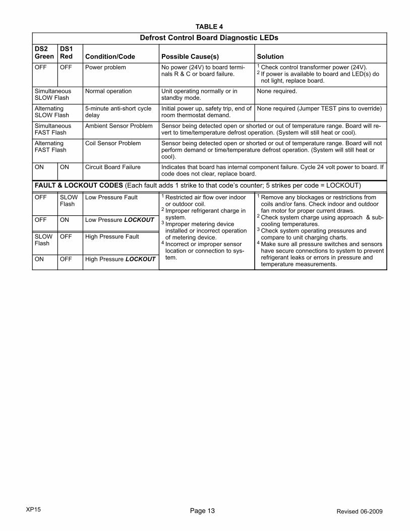
Diagnostic LEDsThe state (Off, On, Flashing) of two LEDs on the defrostboard (DS1 [Red] and DS2 [Green]) indicate diagnosticsconditions that are described in table 4.
Defrost Board Pressure Switch ConnectionsThe unit’s automatic reset pressure switches (LO PS − S87and HI PS − S4) are factory−wired into the defrost board onthe LO−PS and HI−PS terminals, respectively.
Low Pressure Switch (LO−PS)�When the low pressureswitch trips, the defrost board will cycle off the compressor,and the strike counter in the board will count one strike. Thelow pressure switch is ignored under the following condi-tions:
�during the defrost cycle and 90 seconds after the termina-tion of defrost
�when the average ambient sensor temperature is below15° F (−9°C)
�for 90 seconds following the start up of the compressor
�during "test" mode
High Pressure Switch (HI−PS)�When the high pressureswitch trips, the defrost board will cycle off the compressor,and the strike counter in the board will count one strike.
Defrost Board Pressure Switch Settings
High Pressure (auto reset) − trip at 590 psig; reset at 418psig.
Low Pressure (auto reset) − trip at 25 psig; reset at 40 psig.
5−Strike Lockout Feature
The internal control logic of the board counts the pressureswitch trips only while the Y1 (Input) line is active. If a pres-sure switch opens and closes four times during a Y1 (In-put), the control logic will reset the pressure switch tripcounter to zero at the end of the Y1 (Input). If the pressureswitch opens for a fifth time during the current Y1 (Input),the control will enter a lockout condition.
The 5−strike pressure switch lockout condition can be resetby cycling OFF the 24−volt power to the control board or byshorting the TEST pins between 1 and 2 seconds. All timerfunctions (run times) will also be reset.
If a pressure switch opens while the Y1 Out line is engaged,a 5−minute short cycle will occur after the switch closes.
Defrost System Sensors
Sensors connect to the defrost board through a field-re-placeable harness assembly that plugs into the board.Through the sensors, the board detects outdoor ambientand coil temperature fault conditions. As the detected tem-perature changes, the resistance across the sensorchanges. Sensor resistance values can be checked by oh-ming across pins shown in table 3.
NOTE − When checking the ohms across a sensor, be
aware that a sensor showing a resistance value that is not
within the range shown in table 3, may be performing as de-
signed. However, if a shorted or open circuit is detected,
then the sensor may be faulty and the sensor harness will
need to be replaced.
TABLE 3
Sensor Temperature / Resistance Range
Sensor
TemperatureRange °F (°C)
Resistance valuesrange (ohms)
Pins/WireColor
Outdoor −35 (−37) to 120(48)
280,000 to 3750 3 & 4(Black)
Coil −35 (−37) to 120(48)
280,000 to 3750 5 & 6(Brown)
Note: Sensor resistance increases as sensed temperature decreases.

Page 10XP15 Revised 06−2009
FIGURE 11
Sensor Locations
24 tubes up(after April 2006)
SLEEVE
AMBIENT SENSOR − Extendtip of plastic sensor justoutside of plastic sleeve.
Place ambient sensor and wirefrom defrost board inside ofplastic sleeve and route thrugap between corner post andcoil support as shown. Securewith wire tie.
DISCHARGE SENSOR
WIRE TIE
COIL SENSOR −Clip coil temperature sensor from the defrost boardon the return bend shown on models as follows:
Model −024, −030, −036 & −042: 12 tubes up from bottom (11−1/2"); Model −048 & −060 (before April 2006): 16 tubes up from bottom (15−1/2")Model −048 & −060 (after April 2006): 24 tubes up from bottom (23−1/2")
Models −024, −030, −036 & −042 Models −048 & −060
16 tubes up(before April 2006)
12 tubes up
Ambient Sensor�The ambient sensor (shown in detail A,figure 11) considers outdoor temperatures below −35°F(−37°C) or above 120°F (48°C) as a problem. If the ambientsensor is detected as being open, shorted or out of the tem-perature range of the sensor, the board will not perform de-mand defrost operation. The board will revert to time/tem-perature defrost operation and will display the appropriatefault code. Heating and cooling operation will be allowed inthis fault condition.
Coil Sensor�The coil temperature sensor (shown in de-tail B, figure 11) considers outdoor temperatures below−35°F (−37°C) or above 120°F (48°C) as a problem. If thecoil temperature sensor is detected as being open, shortedor out of the temperature range of the sensor, the board willnot perform demand or time/temperature defrost operationand will display the appropriate fault code. Heating andcooling operation will be allowed in this fault condition.
Defrost Temperature Termination Shunt (Jumper)Pins�The defrost board selections are: 50, 70, 90, and100°F (10, 21, 32 and 38°C). The shunt termination pin isfactory set at 50°F (10°C). If the temperature shunt is notinstalled, the default termination temperature is 90°F(32°C).
Delay Mode
The defrost board has a field−selectable function to reduceoccasional sounds that may occur while the unit is cyclingin and out of the defrost mode. When a jumper is installedon the DELAY pins, the compressor will be cycled off for 30seconds going in and out of the defrost mode. Units areshipped with jumper installed on DELAY pins.
NOTE − The 30 second off cycle is NOT functional when
jumpering the TEST pins.
Operational Description
The defrost control board has three basic operationalmodes: normal, calibration, and defrost.
Normal Mode�The demand defrost board monitors the Oline, to determine the system operating mode (heat/cool),outdoor ambient temperature, coil temperature (outdoorcoil) and compressor run time to determine when a defrostcycle is required.
Calibration Mode�The board is considered uncalibratedwhen power is applied to the board, after cool mode opera-tion, or if the coil temperature exceeds the termination tem-perature when it is in heat mode.
Calibration of the board occurs after a defrost cycle to en-sure that there is no ice on the coil. During calibration, thetemperature of both the coil and the ambient sensor aremeasured to establish the temperature differential which isrequired to allow a defrost cycle. See figure 13 for calibra-tion mode sequence.
Defrost Mode�The following paragraphs provide a de-tailed description of the defrost system operation.
Detailed Defrost System Operation
Defrost Cycles�The demand defrost control board initi-ates a defrost cycle based on either frost detection or time.
�Frost Detection�If the compressor runs longer than 30minutes and the actual difference between the clearcoil and frosted coil temperatures exceeds the maxi-mum difference allowed by the control, a defrost cyclewill be initiated.
�Time�If 6 hours of heating mode compressor run timehas elapsed since the last defrost cycle while the coiltemperature remains below 35°F (2°C), the demanddefrost control will initiate a defrost cycle.

Page 11XP15 Revised 06−2009
Actuation�When the reversing valve is de−energized, theY circuit is energized, and the coil temperature is below35°F (2°C), the board logs the compressor run time. If theboard is not calibrated, a defrost cycle will be initiated after30 minutes of heating mode compressor run time. The con-trol will attempt to self−calibrate after this (and all other) de-frost cycle(s).
Calibration success depends on stable system tempera-tures during the 20−minute calibration period. If the boardfails to calibrate, another defrost cycle will be initiated after45 minutes (90 minutes for −1 to −4 boards) of heating modecompressor run time. Once the defrost board is calibrated,it initiates a demand defrost cycle when the difference be-tween the clear coil and frosted coil temperatures exceedsthe maximum difference allowed by the control OR after 6hours of heating mode compressor run time has beenlogged since the last defrost cycle.
NOTE − If ambient or coil fault is detected, the board will not
execute the �TEST" mode.
Termination�The defrost cycle ends when the coil tem-perature exceeds the termination temperature or after 14minutes of defrost operation. If the defrost is terminated bythe 14−minute timer, another defrost cycle will be initiatedafter 30 minutes of run time.
Test Mode�When Y is energized and 24V power is beingapplied to the board, a test cycle can be initiated by placingthe termination temperature jumper across the �Test" pinsfor 2 to 5 seconds. If the jumper remains across the �Test"pins longer than 5 seconds, the control will ignore the testpins and revert to normal operation. The jumper will initiateone cycle per test.
Enter the �TEST" mode by placing a shunt (jumper) acrossthe �TEST" pins on the board after power−up. (The �TEST"pins are ignored and the test function is locked out if theshunt is applied on the �TEST" pins before power−up).Board timings are reduced, the low−pressure switch andloss of charge detection fault is ignored and the board willclear any active lockout condition.
Each test pin shorting will result in one test event. Foreach �TEST" the shunt (jumper) must be removed for atleast 1 second and reapplied. Refer to flow chart (figure 12)for �TEST" operation.
Note: The Y input must be active (ON) and the �O" room
thermostat terminal into board must be inactive.
Defrost Board Diagnostics
See table 4 to determine defrost board operational condi-tions and to diagnose cause and solution to problems.

Page 12XP15 Revised 06−2009
TESTPlacing the jumper on the test pins allows the technician to:
�Clear short cycle lockout
�Clear five−strike fault lockout
�Cycle the unit in and out of defrost mode
�Place the unit in defrost mode to clear the coil
When Y1 is energized and 24V power is being applied to the Demand Defrost Control, a test cyclecan be initiated by placing a jumper on the Demand Defrost Control’s TEST pins for 2 to 5 sec-onds. If the jumper remains on the TEST pins for longer than five seconds, the Demand DefrostControl will ignore the jumpered TEST pins and revert to normal operation.
The control will initiate one test event each time a jumper is placed on the TEST pins. Foreach TEST the jumper must be removed for at least one second and then reapplied.
DEMAND DEFROST CONTROL(UPPER LEFT−HAND CORNER)
JUMPER
NOTE � Placing a jumper on the TEST pins will not bring theunit out of inactive mode. The only way manually activate theheat pump from an inactive mode is to cycle the 24VAC powerto the Demand Defrost Control.
Y1 Active
Place a jumper on TEST pins forlonger than one second but lessthan two seconds.
Clears any short cycle lockout andfive strike fault lockout function, ifapplicable. No other functions willbe executed and unit will continue inthe mode it was operating.
Place a jumper on TEST pins formore than two seconds.
Clears any short cycle lockout andfive strike fault lockout function, ifapplicable.
If in HEATING ModeIf in DEFROST Mode
No further test mode operation willbe executed until the jumper isremoved from the TEST pins andreapplied.
If no ambient or coil sensor ault ex-ist, unit will go into DEFROSTMODE.If ambient or coil faults exist (openor shorted), unit will remain inHEAT MODE.
The unit will terminate defrost andenter HEAT MODE uncalibratedwith defrost timer set for 30 minutetest.
If jumper on TEST pins remains inplace for more than five seconds.
The unit will return to HEAT MODEun−calibrated with defrost timer setfor 30 minutes.
If jumper on TEST pins is removedbefore a maximum of five seconds.
The unit will remain in DEFROSTMODE until termination on time ortemperature.
O Line StatusINACTIVEACTIVE
If in COOLING Mode
FIGURE 12
Page 13XP15 Revised 06−2009
TABLE 4
Defrost Control Board Diagnostic LEDs
DS2Green
DS1Red Condition/Code Possible Cause(s) Solution
OFF OFF Power problem No power (24V) to board termi-nals R & C or board failure.
1 Check control transformer power (24V).2 If power is available to board and LED(s) do
not light, replace board.
SimultaneousSLOW Flash
Normal operation Unit operating normally or instandby mode.
None required.
AlternatingSLOW Flash
5−minute anti−short cycledelay
Initial power up, safety trip, end ofroom thermostat demand.
None required (Jumper TEST pins to override)
SimultaneousFAST Flash
Ambient Sensor Problem Sensor being detected open or shorted or out of temperature range. Board will re-vert to time/temperature defrost operation. (System will still heat or cool).
Alternating FAST Flash
Coil Sensor Problem Sensor being detected open or shorted or out of temperature range. Board will notperform demand or time/temperature defrost operation. (System will still heat orcool).
ON ON Circuit Board Failure Indicates that board has internal component failure. Cycle 24 volt power to board. Ifcode does not clear, replace board.
FAULT & LOCKOUT CODES (Each fault adds 1 strike to that code’s counter; 5 strikes per code = LOCKOUT)
OFF SLOWFlash
Low Pressure Fault 1 Restricted air flow over indooror outdoor coil.
2 Improper refrigerant charge insystem.
3 Improper metering deviceinstalled or incorrect operationof metering device.
4 Incorrect or improper sensorlocation or connection to sys-tem.
1 Remove any blockages or restrictions fromcoils and/or fans. Check indoor and outdoorfan motor for proper current draws.
2 Check system charge using approach & sub-cooling temperatures.
3 Check system operating pressures andcompare to unit charging charts.
4 Make sure all pressure switches and sensorshave secure connections to system to preventrefrigerant leaks or errors in pressure andtemperature measurements.
OFF ON Low Pressure LOCKOUT
SLOWFlash
OFF High Pressure Fault
ON OFF High Pressure LOCKOUT

Page 14XP15 Revised 06−2009
Calibration Mode Sequence
Occurs after power up, after cooling operation, or if the coil temperature exceeds the terminationtemperature while in Heat Mode.
DCB defaults to 30 minutes Time/Temperature ModeReset Compressor Runtime / Reset Three / Five Strike Counter
DEMAND MODEAccumulate compressor run-time while coil temperatureis below 35° F (2°C). Whenthe accumulated compres-sor time exceeds 6 hours orif the coil sensor indicatesfrost is present on coil, go toDefrost.
30 MIN. TIME/TEMP. MODEAccumulate compressor run-time while coil temperatureis below 35° F (2°C). Whenthe accumulated compressortime exceeds 30 minutes goto Defrost.
45 MIN. TIME/TEMP. MODE(90 MIN FOR −1 TO −4 BOARDS)Accumulate compressor runtimewhile coil temperature is below35° F (2°C). When the accumu-lated compressor time exceeds90 minutes go to Defrost.
DEFROSTOUTDOOR FAN OffReversing Valve ON
W1 line ON
Monitor coil temperatureand time in defrost mode.
HOW DID DEFROST TERMINATE?
Coil temperature wasabove 35°F (2°C) for 4min. of the 14 min. de-
frost OR reached defrosttermination temp.
DCB’s 60L3901 and 46M8201LO−PS Termination Option
selected. Defrost terminated bypressure.
Defrosted for 14 min. with-out the coil temp. goingabove 35°F (2°C) for 4
min and coil did not reachtermination temp.
At termination of defrost the compressorruntime counter is reset/Turn on Outdoor
FAN /Rev Valve & W1 turn off.
At Termination of Defrostthe compressor runtimecounter is reset/Turn on
Outdoor FAN/Rev valve &W turn OFF
Attempt to Calibration−Temperature measurements are not takenfor the first few minutes of each heat demand. This is to allow coiltemperatures to stabilize. DCB has a maximum of 20 minutes ofaccumulated compressor runtime in heat mode to calibrate DCB
This may involve more than one heating demand.
YES, calibration occurredWas stable coil temp. attained
within 20 minutes?
NO, DCB reverts to 45 min. (90min. for −1 to −4 boards)
time/temp.
FIGURE 13

Page 15XP15 Revised 06−2009
J−Crankcase Heater (HR1)
Compressors in all units are equipped with a 70 watt belly-
band type crankcase heater. HR1 prevents liquid from ac-
cumulating in the compressor. HR1 is controlled by the
crankcase heater thermostat.
K− Crankcase heater Thermostat (S40)Thermostat S40 controls the crankcase heater in all units.
S40 is located on the liquid line. When liquid line tempera-
ture drops below 50° F the thermostat S40 closes energizing
HR1. The thermostat will open, de−energizing HR1 once liq-
uid line temperature reaches 70° F .
III−REFRIGERANT SYSTEM
IMPORTANTThe Clean Air Act of 1990 bans the intentional vent-ing of (CFC’s and HFC’s) as of July 1, 1992. Approvedmethods of recovery, recycling or reclaiming mustbe followed. Fines and/or incarceration my be leviedfor noncompliance.
Field refrigerant piping consists of liquid and vapor linesfrom the outdoor unit (sweat connections). Use LennoxL15 series line sets as shown in table 5.Separate liquid and suction service ports are provided atthe service valves for connection of gauge manifold duringcharging procedure. Figure 14 shows XP15 refrigerantflow and gauge manifold connections.
TABLE 5
Model
Valve Field Size
ConnectionsRecommended Line Set
LiquidLine
VaporLine
LiquidLine
VaporLine
L15Line Sets
−024−030−036
3/8 in.10 mm
3/4 in.19 mm
3/8 in.10 mm
3/4 in.19 mm
L15−6515 ft. − 50 ft.4.6 m − 15 m
−048−042
3/8 in.10 mm
7/8 in.22 mm
3/8 in.10 mm
7/8 in.22 mm
L15−6515 ft. − 50 ft.4.6 m − 15 m
−0603/8 in.10 mm
1−1/8 in.29 mm
3/8 in.10 mm
1−1/8 in.29 mm
FieldFabricated
XP15 COOLING CYCLE(Showing Gauge Manifold Connections)
NOTE−Use gauge ports on vapor line valve and liquid valve for evacuating refrigerant linesand indoor coil. Use suction gauge port to measure suction pressure during charging.
OUTDOORCOIL
EXPANSION/CHECK VALVE
BI−FLOWFILTER / DRIER
TOHFC−410A
DRUM
LOWPRESSURE
HIGHPRESSURE
COMPRESSOR
REVERSING VALVE
VAPORLINE
VALVE
MUFFLER
NOTE − ARROWS INDICATEDIRECTION OF REFRIGERANT FLOW.
REFRIGERANT WILL FLOW IN OPPOSITEDIRECTION IN HEATING CYCLE.
SERVICE
PORT
SUCTION
EXPANSION/CHECKVALVE
INDOOR UNIT
OUTDOOR UNIT
LIQUIDLINE
SERVICEPORT
GAUGE MANIFOLD
DISTRIBUTOR
INDOORCOIL
FIGURE 14

Page 16XP15 Revised 06−2009
A−Service Valves
Access the liquid line and vapor line service valves (figures15 and 16) and gauge ports are used for leak testing, eva-cuating, charging and checking charge. See table 6 fortorque requirements.
Each valve is equipped with a service port which has a fac-tory−installed Schrader valve. A service port cap protectsthe Schrader valve from contamination and serves as theprimary leak seal.
TABLE 6
Part Recommended Torque
Service valve cap 8 ft.− lb. 11 NM
Sheet metal screws 16 in.− lb. 2 NM
Machine screws #10 28 in.− lb. 3 NM
Compressor bolts 90 in.− lb. 10 NM
Gauge port seal cap 8 ft.− lb. 11 NM
IMPORTANTService valves are closed to the outdoor unit andopen to line set connections. Do not open the valvesuntil refrigerant lines have been leak tested andevacuated. All precautions should be exercised tokeep the system free from dirt, moisture and air.
To Access Schrader Port:
1 − Remove service port cap with an adjustable wrench.
2 − Connect gauge to the service port.
3 − When testing is complete, replace service port cap.Tighten finger tight, then an additional 1/6 turn.
To Open Service Valve:
1 − Remove stem cap with an adjustable wrench.
2 − Using service wrench and hex head extension, backthe stem out counterclockwise as far as it will go.
NOTE − Use a 3/16" hex head extension for liquid linesize.
3 − Replace stem cap and tighten it firmly. Tighten fingertight, then tighten an additional 1/6 turn.
To Close Service Valve:
1 − Remove stem cap with an adjustable wrench.
2 − Using service wrench and hex head extension, turnstem clockwise to seat valve. Tighten it firmly.
NOTE − Use a 3/16" hex head extension for liquid linesize.
3 − Replace stem cap. Tighten finger tight, then tighten anadditional 1/6 turn.
Vapor Line (Ball Type) Valve
Vapor line service valves function the same way as the oth-er valves, the difference is in the construction. Thesevalves are not rebuildable. If a valve has failed, you mustreplace it. A ball valve valve is illustrated in figure 16.
The ball valve is equipped with a service port with a factory−installed Schrader valve. A service port cap protects theSchrader valve from contamination and assures a leak−free seal.
Front-Seated Liquid Line Service Valve
(Valve ShownClosed)Insert hexwrench here
SCHRADERVALVE
SERVICEPORT
To outdoor coil
STEMCAP
STEMCAP
(VALVE front-seated)
To outdoor coil
SCHRADERVALVE
[open to line setwhen valve isclosed (front
seated)]
(Valve Shown Open)insert hex wrench here
To indoor coil
SERVICE PORT CAP
SERVICE PORTSERVICE PORT CAP
To indoor coil
FIGURE 15
Vapor Line (Ball Type) Service Valve (Valve Open)
FIGURE 16
BALL(Shownclosed)
STEM
STEMCAP
SERVICEPORT
SCHRADERVALVE
SERVICEPORT CAP
To indoor coil
To outdoor coil
Use Adjustable WrenchTo close: rotate StemCounter-clockwise 90°.To open: rotate StemClockwise 90°.

Page 17XP15 Revised 06−2009
IV−CHARGING
Units are factory charged with the amount of HFC−410A re-frigerant indicated on the unit rating plate. This charge isbased on a matching indoor coil and outdoor coil with 15 ft.(4.6m) line set. For varying lengths of line set, refer to table7 for refrigerant charge adjustment.
TABLE 7
Liquid Line SetDiameter
Ozs. per 5 ft. (grams per 1.5m) adjust from 15 ft. (4.6m) line set*
3/8 in.(9.5mm)
3 ounces per 5 feet(85g per 1.5m)
*If line length is greater than 15 ft. (4.6m), add this amount.
If line length is less than 15 ft. (4.6), subtract this amount.
A−Leak Testing
After the line set has been connected to the indoor and out-door units, the line set connections and indoor unit must bechecked for leaks.
WARNINGRefrigerant can be harmful if inhaled. Refrigerantmust be used and recovered responsibly. Failureto follow this warning can lead to injury or death.
WARNINGFire, Explosion and Personal Safety Hazard.Failure to follow this warning could result in damage,personal injury or death.Never use oxygen to pressurize or purge refrigera-tion lines. Oxygen when exposed to a spark or openflame can cause damage by fire and or an explosion,that could result in personal injury or death.
WARNINGDanger of explosion. Can cause equipment damage,injury or death. When using a high pressure gassuch as dry nitrogen to pressurize a refrigeration orair conditioning system, use a regulator that cancontrol the pressure down to 1 or 2 psig (6.9 to 13.8kPa).
Using an Electronic Leak Detector
1 − Connect a cylinder of HFC−410A to the center port of
the manifold gauge set.
2 − With both manifold valves closed, open the valve on
the HFC−410A cylinder (vapor only).
3 − Open the high pressure side of the manifold to allow
the HFC−410A into the line set and indoor unit. Weigh
in a trace amount of HFC−410A . [A trace amount is a
maximum of 2 ounces (57 g) or 3 pounds (31 kPa)
pressure.] Close the valve on the HFC−410A cylinder
and the valve on the high pressure side of the manifold
gauge set. Disconnect the HFC−410A cylinder.
4 − Connect a cylinder of nitrogen with a pressure regulat-
ing valve to the center port of the manifold gauge set.
5 − Connect the manifold gauge set high pressure hose to
the vapor valve service port. (Normally, the high pres-
sure hose is connected to the liquid line port; however,
connecting it to the vapor port better protects the man-
ifold gauge set from high pressure damage.)
6 − Adjust the nitrogen pressure to 150 psig (1034 kPa).
Open the valve on the high side of the manifold gauge
set which will pressurize line set and indoor unit.
7 − After a few minutes, open a refrigerant port to ensure
the refrigerant you added is adequate to be detected.
(Amounts of refrigerant will vary with line lengths.)
Check all joints for leaks. Purge nitrogen and
HFC−410A mixture. Correct any leaks and recheck.
IMPORTANTLeak detector must be capable of sensing HFC re-frigerant.
B−Evacuating
Evacuating the system of noncondensables is critical forproper operation of the unit. Noncondensables are definedas any gas that will not condense under temperatures andpressures present during operation of an air conditioningsystem. Noncondensables and water vapor combine withrefrigerant to produce substances that corrode copper pip-ing and compressor parts.
IMPORTANTUse a thermocouple or thermistor electronic vacuumgauge that is calibrated in microns. Use an instrumentthat reads from 50 microns to at least 23,000 microns.
1 − Connect the manifold gauge set to the service valve
ports as follows:
� low pressure gauge to vapor line service valve � high pressure gauge to liquid line service valve
2 − Connect micron gauge.
3 − Connect the vacuum pump (with vacuum gauge) to the
center port of the manifold gauge set.
4 − Open both manifold valves and start vacuum pump.
5 − Evacuate the line set and indoor unit to an absolute
pressure of 23,000 microns (29.01 inches of mercu-
ry). During the early stages of evacuation, it is desir-
able to close the manifold gauge valve at least once to
determine if there is a rapid rise in absolute pressure.
A rapid rise in pressure indicates a relatively large leak.
If this occurs, repeat the leak testing procedure.
NOTE − The term absolute pressure means the total
actual pressure within a given volume or system,
above the absolute zero of pressure. Absolute pres-
sure in a vacuum is equal to atmospheric pressure mi-
nus vacuum pressure.
6 − When the absolute pressure reaches 23,000 microns
(29.01 inches of mercury), close the manifold gauge
valves, turn off the vacuum pump and disconnect the
manifold gauge center port hose from vacuum pump.
Attach the manifold center port hose to a nitrogen cylin-

Page 18XP15 Revised 06−2009
der with pressure regulator set to 150 psig (1034 kPa)
and purge the hose. Open the manifold gauge valves
to break the vacuum in the line set and indoor unit.
Close the manifold gauge valves.
WARNINGDanger of Equipment Damage.Avoid deep vacuum operation. Do not use com-pressors to evacuate a system.Extremely low vacuums can cause internal arcingand compressor failure.Damage caused by deep vacuum operation willvoid warranty.
7 − Shut off the nitrogen cylinder and remove the manifold
gauge hose from the cylinder. Open the manifold
gauge valves to release the nitrogen from the line set
and indoor unit.
8 − Reconnect the manifold gauge to the vacuum pump,
turn the pump on, and continue to evacuate the line set
and indoor unit until the absolute pressure does not
rise above 500 microns (29.9 inches of mercury) within
a 20−minute period after shutting off the vacuum pump
and closing the manifold gauge valves.
9 − When the absolute pressure requirement above has
been met, disconnect the manifold hose from the vacu-
um pump and connect it to an upright cylinder of
HFC−410A refrigerant. Open the manifold gauge valves
to break the vacuum from 1 to 2 psig positive pressure in
the line set and indoor unit. Close manifold gauge
valves and shut off the HFC−410A cylinder and remove
the manifold gauge set.
C−Charging
XP15−XXX−230−01 through XP15−XXX−230−02
This system is charged with HFC−410A refrigerant whichoperates at much higher pressures than HCFC−22.. Thecheck/expansion valve provided with the unit is approvedfor use with HFC−410A. Do not replace it with a valve de-signed for use with HCFC−22.. This unit is NOT approvedfor use with coils which include metering orifices or capil-lary tubes.
Processing Procedure
IMPORTANTMineral oils are not compatible with HFC−410A. If oilmust be added, it must be a polyol ester oil.
It is desirable to charge the system in the cooling cycle ifweather conditions permit. However, if the unit must becharged in the heating season, one of the following proce-dures must be followed to ensure proper system charge.
Charge Using Weigh-in Method�Outdoor Temper-ature < 65ºF (18ºC)
If the system is void of refrigerant, or if the outdoor ambienttemperature is cool, the refrigerant charge should beweighed into the unit. Do this after any leaks have been re-paired.
1−. Recover the refrigerant from the unit.
2−. Conduct a leak check, then evacuate as previouslyoutlined.
3−. Weigh in the unit nameplate charge. If weighing facili-ties are not available or if you are charging the unit dur-ing warm weather, follow one of the other proceduresoutlined below.
Charge using Subcooling Method�Outdoor Tem-
perature < 65ºF (18ºC)
When the outdoor ambient temperature is below 65°F(18°C), use the subcooling method to charge the unit. Itmay be necessary to restrict the air flow through the out-door coil to achieve pressures in the 325−375 psig(2240−2585 kPa) range. These higher pressures are nec-essary for checking the charge. Block equal sections of airintake panels and move obstructions sideways until the liq-uid pressure is in the 325−375 psig (2240−2585 kPa) range.See figure 17.
Blocking Outdoor Coil
BLOCK OUTDOOR COIL ONESIDE AT A TIME WITHCARDBOARD OR PLASTICSHEET UNTIL PROPER TESTINGPRESSURES ARE REACHED.
CARDBOARD OR PLASTICSHEET
FIGURE 17
1−. With the manifold gauge hose still on the liquid serviceport and the unit operating stably, use a digital ther-mometer to record the liquid line temperature.
2−. At the same time, record the liquid line pressure readingin the �(psig___)" space in the table.
3−. Use a temperature/pressure chart for HFC−410A to de-termine the saturation temperature for the liquid linepressure reading.
4−. Subtract the liquid line temperature from the saturationtemperature (according to the chart) to determine sub-cooling.
5−. Compare the subcooling value with those in table 8. Ifsubcooling is greater than shown, recover some refrig-erant; if less, add some refrigerant.
NOTES −
� HFC−410A refrigerant cylinders are rose−colored. Re-frigerant should be added through the vapor valve inthe liquid state.
� Certain HFC−410A cylinders are identified as beingequipped with a dip tube. These allow liquid refrigerantto be drawn from the bottom of the cylinder without in-verting the cylinder. DO NOT turn this type cylinder up-side−down to draw refrigerant.

Page 19XP15 Revised 06−2009
TABLE 8
XP15 Subcooling ValuesXP15−XXX−230−01 through XP15−XXX−230−02
(psig ) � Saturation Temperature
� � Liquid Line Temperature
= � Subcooling Value
Model −024 −030 −036 −042 −048 −060
°F(°C)*
5(2.8)
4(2.2)
4(2.2)
7(3.9)
4(2.2)
2(1.1)
NOTE − For best results, use the same electronic thermometer tocheck both outdoor-ambient and liquid-line temperatures.
*F: +/−1.0°; C: +/−0.5°
Charge Using the Approach Method�Outdoor
Temp. >65ºF (18ºC)
The following procedure is intended as a general guide andis for use on expansion valve systems only. For best results,indoor temperature should be 70°F (21°C) to 80°F (26°C).Monitor system pressures while charging.
1−. Record outdoor ambient temperature using a digitalthermometer.
2−. Attach high pressure gauge set and operate unit forseveral minutes to allow system pressures to stabilize.
3−. Compare stabilized pressures with those provided intable 10, �Normal Operating Pressures."
Minor variations in these pressures may be expecteddue to differences in installations. Significant differ-ences could mean that the system is not properlycharged or that a problem exists with some componentin the system. Pressures higher than those listed indi-cate that the system is overcharged. Pressures lowerthan those listed indicate that the system is under-charged. Verify adjusted charge using the approachmethod.
4−. Use the same digital thermometer used to check out-door ambient temperature to check liquid line tempera-ture. Verify the unit charge using the approach method.
5−. The difference between the ambient and liquid temper-atures should match values given in table 9.
TABLE 9
XP15 Approach ValuesXP15−XXX−230−01 through XP15−XXX−230−02
� Liquid Line Temperature
� � Outdoor Temperature
= � Approach Temperature
Model −024 −030 −036 −042 −048 −060
°F(°C)*
11.5(6.4)
14.5(8)
15(8.3)
16(8.9)
11(6.1)
14.4(8)
NOTE − For best results, use the same electronic thermometer tocheck both outdoor-ambient and liquid-line temperatures.
*F: +/−1.0°; C: +/−0.5°
6−. If the values don’t agree with the those in table 9, addrefrigerant to lower the approach temperature or re-cover refrigerant from the system to increase the ap-proach temperature.
IMPORTANTUse table 10 as a general guide when performingmaintenance checks. This is not a procedure forcharging the unit (Refer to Charging/CheckingCharge section). Minor variations in these pressuresmay be expected due to differences in installations.Significant differences could mean that the systemis not properly charged or that a problem exists withsome component in the system.
Table 10
XP15−XXX−230−01 through XP15−XXX−230−02
Normal Operating Pressure − Liquid +10 & Vapor +5 PSIG*
�F (�C)**
XP15−024 XP15−030 XP15−036 XP15−042 XP15−048 XP15−060
Liquid Vapor Liquid Vapor Liquid Vapor Liquid Vapor Liquid Vapor Liquid Vapor
Heating Operation
20 (−7.0) 304 64 318 63 270 61 283 58 329 62 330 59
30 (−1.0) 322 79 330 68 284 73 301 71 358 77 350 71
40 (4.4) 336 95 348 90 302 88 327 87 385 92 353 72
50 (10) 360 114 380 109 315 105 345 104 411 111 394 104
Cooling Operation
65 (18.3) 234 140 248 138 249 141 262 143 232 133 238 136
75 (23.9) 282 139 287 139 289 143 308 145 269 138 278 138
85 (29.4) 313 143 331 141 334 145 354 146 312 141 321 140
95 (35.0) 372 146 381 143 383 148 406 148 362 143 372 142
105 (40.6) 413 147 431 145 435 150 418 146 418 146 424 144
115 (49.0) 470 151 489 148 496 153 484 150 484 150 484 147
*These are most−popular−match−up pressures. Indoor match up, indoor air quality, and indoor load cause pressures to vary.
**Temperature of the air entering the outdoor coil.

Page 20XP15 Revised 06−2009
XP15−XXX−230−04
IMPORTANTIf unit is equipped with a crankcase heater, it shouldbe energized 24 hours before unit start−up to preventcompressor damage as a result of slugging.
1−. Rotate fan to check for frozen bearings or binding.
2−. Inspect all factory− and field−installed wiring for looseconnections.
3−. After evacuation is complete, open the liquid line andvapor line service valves to release the refrigerantcharge (contained in outdoor unit) into the system.
4−. Replace the stem caps and tighten as specified in Op-erating Service Valves.
5−. Check voltage supply at the disconnect switch. Thevoltage must be within the range listed on the unit’snameplate. If not, do not start the equipment until youhave consulted with the power company and the volt-age condition has been corrected.
6−. Set the thermostat for a cooling demand. Turn on pow-er to the indoor indoor unit and close the outdoor unitdisconnect switch to start the unit.
7−. Recheck voltage while the unit is running. Power mustbe within range shown on the nameplate.
8−. Check system for sufficient refrigerant by using theprocedures listed under Testing and Charging System.
TESTING AND CHARGING SYSTEM
This system uses HFC−410A refrigerant which operates atmuch higher pressures than HCFC−22. The pre−installedliquid line filter drier is approved for use with HFC−410Aonly. Do not replace liquid line filter drier with componentsdesigned for use with HCFC−22.
NOTE − This unit is NOT approved for use with coils which
use capillary tubes as a refrigerant metering device.
SETTING UP TO CHECK CHARGE
1−. Close manifold gauge set valves. Connect the centermanifold hose to an upright cylinder of HFC−410A.
2−. Connect the manifold gauge set to the unit’s serviceports as illustrated in figure 18.
� low pressure gauge to vapor service port
� high pressure gauge to liquid service port
COOLING MODE INDOOR AIRFLOW CHECK
Check airflow using the Delta−T (DT) process as illustrated
in figure 19.
HEATING MODE INDOOR AIRFLOW CHECK
Blower airflow (CFM) may be calculated by energizingelectric heat and measuring:
�temperature rise between the return air and supply airtemperatures at the indoor coil blower unit,
�voltage supplied to the unit,
�amperage being drawn by the heat unit(s).
Then, apply the measurements taken in following formulato determine CFM:
CFM =Amps x Volts x 3.41
1.08 x Temperature rise (F)
CALCULATING CHARGE
If the system is void of refrigerant, first, locate and repairany leaks and then weigh in the refrigerant charge into theunit. To calculate the total refrigerant charge:
Amountspecifiedonnameplate
Adjust amount forvariation in line setlength (table infigure 20)
Additional chargespecified per indoorunit match−up(tables 12 through17)
Totalcharge
+ + =
NOTE − Use gauge ports on vapor line valve and liquid valve for evacuating refrigerantlines and indoor coil. Use vapor gauge port to measure vapor pressure during charging.
OUTDOORCOIL
CHECKEXPANSION VALVE
BI−FLOWFILTER /DRIER
TOHFC−410A DRUM
LOWPRESSURE
COMPRESSOR
REVERSING VALVE
VAPOR LINEVALVE
MUFFLER
NOTE − ARROWS INDICATEDIRECTION OF REFRIGERANT FLOW
CHECK EXPANSION VALVE
INDOOR UNIT
OUTDOOR UNIT
LIQUIDSERVICE
PORTGAUGE
MANIFOLD
DISTRIBUTOR
INDOORCOIL
VAPORSERVICEPORT
HIGHPRESSURE
LIQUIDLINEVALVE
Figure 18. XP15 Cooling Cycle (Showing Gauge Manifold Connections)

Page 21XP15 Revised 06−2009
1. Determine the desired DT�Measure entering air temper-ature using dry bulb (A) and wet bulb (B). DT is the intersect-ing value of A and B in the table (see triangle).
2. Find temperature drop across coil�Measure the coil’s drybulb entering and leaving air temperatures (A and C). Tem-perature Drop Formula: (TDrop) = A minus C.
3. Determine if fan needs adjustment�If the difference be-tween the measured TDrop and the desired DT (TDrop–DT) iswithin +3º, no adjustment is needed. See examples: AssumeDT = 15 and A temp. = 72º, these C temperatures would ne-cessitate stated actions:
Cº TDrop – DT = ºF ACTION
53º 19 – 15 = 4 Increase the airflow
58º 14 – 15 = −1 (within +3º range) no change
62º 10 – 15 = −5 Decrease the airflow
4. Adjust the fan speed�See indoor unit instructions to in-crease/decrease fan speed.
Changing air flow affects all temperatures; recheck tempera-tures to confirm that the temperature drop and DT are within+3º.
DT80 24 24 24 23 23 22 22 22 20 19 18 17 16 15
78 23 23 23 22 22 21 21 20 19 18 17 16 15 14
76 22 22 22 21 21 20 19 19 18 17 16 15 14 13
74 21 21 21 20 19 19 18 17 16 16 15 14 13 12
72 20 20 19 18 17 17 16 15 15 14 13 12 11 10
70 19 19 18 18 17 17 16 15 15 14 13 12 11 10
57 58 59 60 61 62 63 64 65 66 67 68 69 70
Temp.of airenteringindoorcoil ºF
INDOORCOIL
DRY BULBDRYBULB
WETBULB
B
TDrop
19º
AD
ry−b
ulb
Wet−bulb ºF
A
72º
B
64º
C
53º
air flowair flow
All temperatures areexpressed in ºF
Figure 19. Checking Indoor Airflow over Evaporator Coil using Delta−T Chart
WEIGH IN 1. Check Liquid and suction line pressures
2. Compare unit pressures with table 11,Normal Operating Pressures.
3. Conduct leak check; evacuate aspreviously outlined.
4. Weigh in the unit nameplate charge plusany charge required for line setdifferences over feet.
Liquid Line
Set Diameter
Ounces per 5 feet (g per 1.5 m)adjust from 15 feet (4.6 m) line set*
3/8" (9.5 mm) 3 ounce per 5’ (85 g per 1.5 m)
NOTE − *If line length is greater than 15 ft. (4.6 m), add thisamount. If line length is less than 15 ft. (4.6 m), subtract thisamount.
Refrigerant Charge per Line Set Length
This nameplate is for illustration
purposes only. Go to actual nameplate
on outdoor unit for charge information.
Figure 20. Using Weigh In Method

Page 22XP15 Revised 06−2009
1 Check the airflow as illustrated in figure 19 to be sure the indoor airflow is asrequired. (Make any air flow adjustments before continuing with the followingprocedure.)
2 Measure outdoor ambient temperature; determine whether to use cooling modeor heating mode to check charge.
3 Connect gauge set.
4 Check Liquid and Vapor line pressures. Compare pressures with NormalOperating Pressures table 11, (The reference table is a general guide. Expectminor pressure variations. Significant differences may mean improper charge orother system problem.)
5 Set thermostat for heat/cool demand, depending on mode being used:
Using cooling mode�When the outdoor ambient temperature is 60°F (15°C) andabove. Target subcooling values in table below are based on 70 to 80°F (21−27°C)indoor return air temperature; if necessary, operate heating to reach that temperaturerange; then set thermostat to cooling mode setpoint to 68ºF (20ºC). When pressureshave stabilized, continue with step 6.
Using heating mode�When the outdoor ambient temperature is below 60°F (15°C).Target subcooling values in table below are based on 65−75°F (18−24°C) indoorreturn air temperature; if necessary, operate cooling to reach that temperature range;then set thermostat to heating mode setpoint to 77ºF (25ºC). When pressures havestabilized, continue with step 6.
6 Read the liquid line temperature; record in the LIQº space.
7 Read the liquid line pressure; then find its corresponding temperature in thetemperature/ pressure chart listed in table 18 and record it in the SATº space.
8 Subtract LIQº temp. from SATº temp. to determine subcooling; record it in SCº space.
9 Compare SCº results with table below, being sure to note any additional charge forline set and/or match−up.
10 If subcooling value is greater than shown in tables 12 through 17 for the applicableunit, remove refrigerant; if less than shown, add refrigerant.
11 If refrigerant is added or removed, repeat steps 6 through 10 to verify charge.
USE COOLINGMODE
USE HEATINGMODE
60ºF (15º)
SATº
LIQº –
SCº =
SUBCOOLING
Figure 21. Using Subcooling Method
Table 11. Normal Operating Pressure − Liquid +10 and Vapor +5 PSIG*
IMPORTANTMinor variations in these pressures may be expected due to differences in installations. Significant differencescould mean that the system is not properly charged or that a problem exists with some component in the system.
XP15−XXX−230−03
�F (�C)**
XP15−024 XP15−030 XP15−036 XP15−042 XP15−048 XP15−060
Liquid Vapor Liquid Vapor Liquid Vapor Liquid Vapor Liquid Vapor Liquid Vapor
HEATING OPERATION
20 (−7.0) 315 65 308 62 284 59 293 58 312 62 349 61
30 (−1.0) 340 81 317 76 296 71 312 71 332 76 375 74
40 (4.4) 364 97 339 89 313 87 321 82 353 92 384 88
50 (10) 394 115 359 107 326 106 337 103 374 110 406 107
COOLING OPERATION
65 (18.3) 237 141 250 141 260 139 265 141 242 139 255 136
75 (23.9) 274 143 292 143 298 141 309 144 279 140 297 138
85 (29.4) 319 145 336 145 344 143 360 147 322 142 343 140
95 (35.0) 364 147 385 147 393 145 408 149 370 144 392 142
105 (40.6) 415 149 438 148 446 148 462 151 423 147 447 145
115 (49.0) 469 152 497 151 506 150 522 154 479 149 510 148
*These are most−popular−match−up pressures. Indoor match up, indoor air quality, and indoor load cause pressures to vary.
**Temperature of the air entering the outdoor coil.

Page 23XP15 Revised 06−2009
INDOOR UNIT MATCHUPS � XP15−XXX−230−03 or HigherTable 12. XP15−024−230−03
INDOOR MATCHUPS
TargetSubcooling
Heat Cool
*Addchargeg
Heat Cool(+5ºF)���(+1ºF) lb oz
CH23−51 14 6 0 14
CBX27UH−030−230 13 6 2 4
CB30U−31 15 5 0 1
CBX32M−030 15 5 0 1
CBX32M−036 13 6 2 4
CBX32MV−024/030 15 5 0 0
CBX32MV−036 13 6 2 4
CBX40UHV−024, −030 15 5 0 0
CBX40UHV−036 13 6 2 4
CH33−42 14 6 0 14
CR33−48 38 7 3 1
CX34−31 15 5 0 1
CX34−38 SN# 6007 and after 6 6 1 15
CX34−38 before SN# 6007 13 6 1 15
Table 13. XP15−030−230−03
INDOOR MATCHUPS
TargetSubcooling
Heat Cool
*Addchargeg
Heat Cool(+5ºF)���(+1ºF) lb oz
CR33−48 31 4 0 13
CH23−51 13 5 0 4
CBX27UH−030−230 12 5 0 10
CBX27UH−036−230 13 5 0 8
CB30U−31 14 5 0 0
CB30U−41/46 12 5 0 10
CBX32M−030 14 5 0 0
CBX32M−036 12 5 0 10
CBX32MV−024/030 14 5 0 0
CBX32MV−036 12 5 0 10
CBX40UHV−024, −030 14 5 0 0
CBX40UHV−036 12 5 0 10
CX34−38 SN# 6007 and after 5 5 0 8
CX34−38 before SN# 6007 13 5 0 8
CX34−43 9 5 1 4
CX34−49 6 5 2 0
CX34−50/60C 9 5 1 4
Table 14. XP15−036−230−03
INDOOR MATCHUPS
TargetSubcooling
Heat Cool
*Addchargeg
Heat Cool(+5ºF)���(+1ºF) lb oz
C33−44C 13 4 0 3
CBX27UH−036−230 13 4 0 3
CBX27UH−042−230 5 5 0 12
CB30U−41/46 13 4 0 3
CB30U−51 5 5 0 12
CBX32M−042 13 4 0 3
CBX32M−048 5 5 0 12
CBX32MV−036 13 4 0 3
CBX32MV−048 5 5 0 12
CBX40UHV−036 13 4 0 3
CBX40UHV−042, −048 5 5 0 12
CH33−42 14 4 0 1
CH33−44/48B 9 4 0 7
CH33−48C 7 5 0 7
CH33−49C 5 5 0 12
CH33−62D 5 7 0 14
CR33−48C 37 4 0 5
CR33−50/60 32 5 0 10
CX34−31 15 4 0 0
CX34−38 SN# 6007 and after 4 4 0 3
CX34−38 before SN# 6007 13 4 0 3
CX34−43 7 5 0 7
CX34−44/48 13 4 0 3
CX34−49 6 5 0 11
Table 15. XP15−042−230−03
INDOOR MATCHUPS
TargetSubcooling
Heat Cool
*Addchargeg
Heat Cool(+5ºF)���(+1ºF) lb oz
C33−44C 13 4 0 0
CH33−62D 7 7 0 13
CBX27UH−042−230 9 4 0 11
CBX27UH−048−230 9 4 0 11
CB30U−51*P 9 4 0 11
CBX32M−048 9 4 0 11
CBX32MV−048 9 4 0 11
CBX40UHV−042, −048 9 4 0 11
CH33−44/48B, −48C 12 4 0 5
CH33−49C 9 4 0 12
CR33−48 35 3 0 2
CX34−38 SN# 6007 and after 4 4 0 0
CX34−38 before SN# 6007 13 4 0 0
CX34−43 12 4 0 5
CX34−44/48B 13 4 0 0
CX34−50/60C 12 4 0 5
Table 16. XP15−048−230−03
INDOOR MATCHUPS
TargetSubcooling
Heat Cool
*Addchargeg
Heat Cool(+5ºF)���(+1ºF) lb oz
CH23−68 21 4 0 12
CBX27UH−048−230 22 4 0 3
CBX27UH−060−230 12 4 0 11
CB30U−51*P 22 4 0 3
CB30U−65*P 12 4 0 3
CBX32M−048 22 4 0 3
CBX32M−060 12 4 0 3
CBX32MV−048 22 4 0 3
CBX32MV−060 12 4 0 3
CBX32MV−068 12 4 0 7
CBX40UHV−048 22 4 0 3
CBX40UHV−060 12 4 0 3
CH33−62D 12 4 0 8
CX34−49C 13 4 0 2
CX34−60D 14 4 0 0
CX34−62D 12 4 0 5
Table 17. XP15−060−230−03
INDOOR MATCHUPS
TargetSubcooling
Heat Cool
*Addchargeg
Heat Cool(+5ºF)���(+1ºF) lb oz
CH23−68 28 6 0 0
CBX27UH−060−230 17 6 0 0
CB30U−51*P, −65*P 19 6 0 2
CBX32M−048*P, −060*P 19 6 0 2
CBX32MV−048*P, −060*P 19 6 0 2
CBX40UHV−048, −060 19 6 0 2
CH33−62D 18 6 0 1
*Amount of charge required in addition to charge shown on unitnameplate. (Remember to consider lineset length difference.)

Page 24XP15 Revised 06−2009
Table 18. HFC−410A Temperature (°F) − Pressure (Psig)
°F Psig °F Psig °F Psig °F Psig
32 100.8 63 178.5 94 290.8 125 445.9
33 102.9 64 181.6 95 295.1 126 451.8
34 105.0 65 184.3 96 299.4 127 457.6
35 107.1 66 187.7 97 303.8 128 463.5
36 109.2 67 190.9 98 308.2 129 469.5
37 111.4 68 194.1 99 312.7 130 475.6
38 113.6 69 197.3 100 317.2 131 481.6
39 115.8 70 200.6 101 321.8 132 487.8
40 118.0 71 203.9 102 326.4 133 494.0
41 120.3 72 207.2 103 331.0 134 500.2
42 122.6 73 210.6 104 335.7 135 506.5
43 125.0 74 214.0 105 340.5 136 512.9
44 127.3 75 217.4 106 345.3 137 519.3
45 129.7 76 220.9 107 350.1 138 525.8
46 132.2 77 224.4 108 355.0 139 532.4
47 134.6 78 228.0 109 360.0 140 539.0
48 137.1 79 231.6 110 365.0 141 545.6
49 139.6 80 235.3 111 370.0 142 552.3
50 142.2 81 239.0 112 375.1 143 559.1
51 144.8 82 242.7 113 380.2 144 565.9
52 147.4 83 246.5 114 385.4 145 572.8
53 150.1 84 250.3 115 390.7 146 579.8
54 152.8 85 254.1 116 396.0 147 586.8
55 155.5 86 258.0 117 401.3 148 593.8
56 158.2 87 262.0 118 406.7 149 601.0
57 161.0 88 266.0 119 412.2 150 608.1
58 163.9 89 270.0 120 417.7 151 615.4
59 166.7 90 274.1 121 423.2 152 622.7
60 169.6 91 278.2 122 428.8 153 630.1
61 172.6 92 282.3 123 434.5 154 637.5
62 175.4 93 286.5 124 440.2 155 645.0
V−SERVICE AND RECOVERY
WARNINGPolyol ester (POE) oils used with HFC−410A refrig-erant absorb moisture very quickly. It is very impor-tant that the refrigerant system be kept closed asmuch as possible. DO NOT remove line set caps orservice valve stub caps until you are ready to makeconnections.
IMPORTANTUse recovery machine rated for HFC−410A refrig-erant.
If the XP15 system must be opened for any kind of service,such as compressor or filter drier replacement, you musttake extra precautions to prevent moisture from enteringthe system. The following steps will help to minimize theamount of moisture that enters the system during recoveryof R410A.
1 − Use a regulator−equipped nitrogen cylinder to break
the system vacuum. Do not exceed 5 psi. The dry ni-
trogen will fill the system, and will help purge any mois-
ture.
2 − Remove the faulty component and quickly seal the
system (using tape or some other means) to prevent
additional moisture from entering the system.
3 − Do not remove the tape until you are ready to install
new component. Quickly install the replacement com-
ponent.
4 − Evacuate the system to remove any moisture and oth-
er non−condensables.
The XP15 system MUST be checked for moisture any
time the sealed system is opened.
Any moisture not absorbed by the polyol ester oil can be re-moved by triple evacuation. Moisture that has been ab-sorbed by the compressor oil can be removed by replacingthe filter drier.
IMPORTANTEvacuation of system only will not remove mois-ture from oil. Filter drier must be replaced to elimi-nate moisture from POE oil.
VI−MAINTENANCE
WARNINGElectric shock hazard. Can cause inju-ry or death. Before attempting to per-form any service or maintenance, turnthe electrical power to unit OFF at dis-connect switch(es). Unit may havemultiple power supplies.
Maintenance and service must be performed by a quali-fied installer or service agency. At the beginning of eachcooling or heating season, the system should be checkedas follows:
Outdoor Unit
1 − Clean and inspect outdoor coil (may be flushed with a
water hose). Ensure power is off before cleaning.
2 − Outdoor unit fan motor is prelubricated and sealed. No
further lubrication is needed.
3 − Visually inspect all connecting lines, joints and coils for
evidence of oil leaks.
4 − Check all wiring for loose connections.
5 − Check for correct voltage at unit (unit operating).
6 − Check amp−draw on outdoor fan motor and compres-
sor (high and low capacity).
7 − Inspect drain holes in coil compartment base and
clean if necessary.
NOTE − If owner complains of insufficient cooling, the unit
should be gauged and refrigerant charge checked. Refer to
section on refrigerant charging in this instruction.
VII−BRAZING
Before brazing remove access panels and any piping pan-els to avoid burning off paint. Be aware of any componentsie, service valves, reversing valve, pressure switches thatmay be damaged due to brazing heat.

Page 25XP15 Revised 06−2009
When making line set connections, use 1 to 2 psig dry nitro-gen to purge the refrigerant piping. This will help to preventoxidation into the system.
WARNINGDanger of explosion: Can cause equipment damage,injury or death. When using a high pressure gassuch as dry nitrogen to pressurize a refrigeration orair conditioning system, use a regulator that cancontrol the pressure down to 1 or 2 psig (6.9 to 13.8kPa).
1 − .Cut ends of copper square (free from nicks or dents).
Debur the ends. The pipe must remain round, do not
pinch end of line.
2 − Wrap wet rag around any components that may be da-
maged.
3 − Use silver alloy brazing rods (5 or 6 percent minimum
silver alloy for copper to copper brazing or 45 percent
silver alloy for copper to brass or copper to steel braz-
ing) which are rated for use with HCFC−22. and
HFC−410A refrigerant.
4 − After brazing quench the joints with a wet rag to prevent
possible heat damage to any components.
VIII−DIAGRAM / OPERATING SEQUENCE

Page 26XP15 Revised 06−2009
Sequence of Operation XP15−024/060
CoolingTransformer from indoor unit supplies 24VAC power to
the thermostat and outdoor unit controls.
1− Internal wiring energizes terminal O by cooling mode
selection, energizing the reversing valve. Cooling de-
mand initiates at Y1 in the thermostat.
2− Defrost board A108 proves N.C high pressure switch
S4 and N.C. low pressure switch S87 energizing com-
pressor contactor K1.
3− K1−1 N.O. closes energizing compressor B1 and out-
door fan motor B4.
Heating
1− Internal wiring de−energizes terminal O by heating
mode selection, de−energizing the reversing valve.
Heating demand initiates at Y1.
2− Defrost board A108 proves N.C high pressure switch
S4 and N.C. low pressure switch S87 energizing com-
pressor contactor K1.
3− K1−1 N.O. closes energizing compressor B1 and out-
door fan motor B4.
Defrost ModeWhen a defrost cycle is initiated, the control ener-
gizes the reversing valve solenoid and turns off the
condenser fan. The control will also put 24VAC on
the �W1" (auxiliary heat) line. The unit will stay in this
mode until either the coil sensor temperature is
above the selected termination temperature, the de-
frost time of 14 minutes has been completed, or the
room thermostat demand cycle has been satisfied.
(If the temperature select shunt is not installed, the
default termination temperature will be 90°F.) If the
room thermostat demand cycle terminates the
cycle, the defrost cycle will be held until the next
room thermostat demand cycle. If the coil sensor
temperature is still below the selected termination
temperature, the control will continue the defrost
cycle until the cycle is terminated in one of the meth-
ods mentioned above. If a defrost is terminated by
time and the coil temperature did not remain above
35°F (2°C) for 4 minutes the control will go to the
30−minute Time/Temperature mode.