SERVICE INSTRUCTIONS AND PARTS LIST M14 … MT14 manual.pdf · 6-5 MI'I-H BULLETIN 555 -PAGE 3...
61
I SSUED DECEMBER 1 95q LLET I N 555E - PAGE I SERVICE INSTRUCTIONS AND PARTS LIST M14 SERIES H LIGHT SECTION CARS This bulletin contains complete instructions for the operation and care of s tandard M14 series H group 1- and later light section cars with ba ttery ignition and direc t belt drive as illustrated above, and lis t s all spare parts for them. Before starting engine or car, read pages 5 to 9. Before ordering spare parts, read page 20. The table of conten ts on pages 2 and 3 permits of quickly locating any infotmation desired� Use it and save time. If car is magneto e quipped, see bulletin 559 for startin instructions, and also for magneto and magneto drive parts. FAIRMONT RAILWAY MOTORS, Inc. FAIRMONT, MINNESOTA, U. S. A. DISTRICT OFFICES Cbinago New York Washington, D. C. St. Louis Fairmont RESIDENT REPRESENTATIVES Texas Virginia Califoia CANADA: Fairmont Railway Motors, Ltd., Toronto, ont. DID int In U. S. A. Copyright 1946 by Fairmont Railway MotOrs, Inc.
Transcript of SERVICE INSTRUCTIONS AND PARTS LIST M14 … MT14 manual.pdf · 6-5 MI'I-H BULLETIN 555 -PAGE 3...

I SSUED DECEMBER 1 95q BULLET I N 555E - PAGE I
SERVICE INSTRUCTIONS AND PARTS LIST
M14 SERIES H LIGHT SECTION CARS
This bulletin contains complete instructions for the opera tion and care of s tandard M 1 4 s e ries H g r oup 1- and later lig h t section cars with b a t tery ignition and direct belt d rive as illu s t rated above, and lis t s all spare parts for t hem.
Before starting engine o r car, read pages 5 t o 9.
Before ordering spare parts, read page 20.
T h e table of contents on pages 2 and 3 permits of quickly locating any infotmation desired� Use it and save time.
If car is magn e t o e quipped, see bulletin 559 for s t a rtinf! ins tr u c tions, and also for magneto and magneto d rive parts.
FAIRMONT RAILWAY MOTORS, Inc. FAIRMONT, MINNESOTA, U. S. A.
DISTRICT OFFICES
Cbinago New York Washington, D. C. St. Louis Fairmont
RESIDENT REPRESENTATIVES
Texas Virginia California
lN CANADA: Fairmont Railway Motors, Ltd., Toronto, ont.
DID Printed In U. S. A.
Copyright 1946 by Fairmont Railway MotOrs, Inc.

PAGE 2 - BULLETIN 555 M14-H 6-5�
TO OPERATORS OF FA I RMONT Mlq SER I ES H MOTOR CARS
This bulletin contains instructions and spare parts for s tandard M14 series H group 1 and later mo tor cars having b a t t e r y i g n i t ion and d i r e c t b e l t drive. Accessories, t h e i r main parts, and some maintenance tools are found on pages 46 t h rough 53, I t ems used on cars having f igures in t he space on t h e name plate marked nspecialn and d i f ferent from those used on s t andard cars, are listed under that special car designation, see page 55.
Upon r e c e i p t of t h i s book prompt l y fill in t he c a r and e n g i n e record on page 2 0 , and always mention t h e s e factory numbers w h en w r i t ing abou t t h e c a r o r ordering parts. Take good care o f t h i s b ook s o i t i s a v a i l a b l e f o r reference when making adj ustments and repairs, o r ordering spare parts.
Max imum capac i t y of car is 1 2 0 0 lbso at ordinary speeds.
TABLE OF CONTENTS
A i r Cleaner - Oil Bath Type (accessory) Air Cleaner - Open Screen Type (maintenance) Air Cleaner - Open Screen Type (spare parts) Ammeters {accessory) . • • • • • • . . • • . Axles and Axle Bearings (instructions) . • •
Axles and Axle Bearings {spare parts 1-5/16 " ) Axles and Axle Bearings !spare parts 1-7/1611) Battery Igni tion (instructions) Battery Ignition (spare parts) Belt Idler {instructions) Belt Idler ! spare parts) Brake {instructions) Brake (spare parts! Cab Top {accessory) Canvas Cover {accessory) Car Complete Less Engine Car Frame and Housing (instructions) Car Identification • • • •
Carbon Depos its o o • • . • o • •
Carburetor {instructions) Carburetor - Type C5 (spare parts ) Carburetor { c on t rol parts) • • •
Condenser Cooling (spare parts ) Connecting Rod (instruct ions) Connecting Rod !spare parts) o Cooling System !instructions) Cooling System (spare parts) •
Couplers (accessory) o • , • .
Crankshaft and Roller Bearings ( instructions) Crankshaft and Roller Bearings ( spare parts) Cylinder and Crankcase !spare parts) Cylinder Head • • • o • • . . • o •
Differential Axle !instructions) • • o o
Differential Axle ! spare parts 1-5/16 " 1 Differential Axle (spare parts 1-7/16" J Endless Cord Belt Drive (instructions) Endless Cord Belt Drive (spare parts) Engine and Mounting ( instructions ) Engine and Mounting (spare parts) Extension Lift Handles •
Flywheels !instructions} •
Flywheels !spare partsl Frame and Deck ! spare parts ) Fuel Sys tern l i n s true tions l •
Fuel System ! spare partsl General Suggestions - Safety First
50 16 31 53
9 54 37
13, 14 35
8 41 11 3 9
48,49 4 6 42 12 20 19 16 29 31 25
16, 17 24 12 25 52
17,18,19 27 25 19
9 54 37
8, 9 41 12 43 45 17 27
42,43 12 31
8
6-5� MI'I-H BULLETIN 555 - PAGE 3
Generator, Lights lbatteryless - accessory! Generator, Lights, and Storage Battery laccessoryl Gongs (accessory! Housing (spare parts ) How t h e Engine Operates How to Order . . •
Insulation - Wheel Hubs !instructions - see wheels! Insulation - Wheel Hubs (spare parts 1-5/161'1 Insulation - Wheel Hubs (spare parts 1-7/1611 I Lubrication Mixing O i l and Gasoline Muffler (accessory) Oil Recommendations Operating the Car Piston (instructions) Piston (spare parts) •
Preparing Car for Service Pulley - Blade Type l accessoryJ Pulleys !instructions) . Pulleys (spare parts) Rail Skids !spare parts) Rail Sweeps laccessory l , Reversing Engine (battery ignition) . Roller Bearings - Engine (instructions) Roller Bearings - Engine (spare partsl Safety First - General Suggestions . • .
Side Bearing Casings (spare parts) . . •
Side Bearing Casings (removal - see crankshaft and roller bearing s ) . Side Exhaust ipart s l . . . Spark Coil !instructions) Spark Coil (spare parts) . Spark Plug ( instructions l Spark Plug isee battery ignition equipment ) Starting and Stopping Engine Starting Crank !parts) . Throttle {instructions) Throttle (control parts) Throttle (spare parts ) . Th-rust Collars !adjustment - see wheel alignment ) Thrust Collars !spare parts 1-5/1611) •
Thrust Collars ( spare parts 1-7 /tsrr J •
Timer - Adjustable Weatherseald (instructions) Timer - Adj ustable Weatherseald (spare parts) Timer - Weatherseald (instructions) Timer - Weatherseald (spare parts ) Timer Control !spare parts ! Tool Box (spare parts) Tools !accessory) Tools !spare parts) Water Hopper !spare parts) Weight and Numerical Part Index Wheels ( instruction} Wheels !spare parts) Wheel A l ignment Windshields (accessory) Windshield (aluminum - accessory) Wipers iwindshield - accessory)
52 50 52 45 13 20
9 54 37
8 5
51 5 7
17 24
5 50
9 41 43 51
7 17 27
8 27
17,18 27 14 35 14 35
6, 7 27 19 31 25
10,11 54 37
14A, 14B 32 15 3 3 3 1 35 53 35 25
21-23 9, 10
37 10,11
46 47 49
PAGE �- BULLETI N 555 NIL!-H
TIMER L IDLER LEVER
5-%
CAP
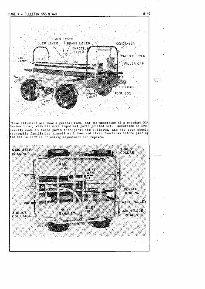
These illustrations show a general view, and the underside- of a s tandard Ml4 Series H car, with the more important parts pointed o u t . Reference is fre
quently made to t h e se part s t h r o u g h o u t t h e b u lle�n, and the user should thoroughly familiarize himself w i t h them and t h e i r functions before placing the car in service or making adj ustment and repairs.

5-53
PREPAR I NG CAR FOR SERV I C E
M I X I NG O I L AND GASOL I NE
O I L R ECOMMENDATI ONS
Mlq-H BULLETIN 555 - PAGE 5
Inspect everything for possible damage i'n transit. If in bad condition make a full report to supervising officials at once. Be sure switch button on car seat is down, then attach high tension cable to spark plug and connect the loosened wire in battery box. If not sure where to attach this wire see diagram on page 14. Examine all bolts, nuts, and electrical connections for tightness. See that all cotter pins are spread open.
Fill the grease gun with a grease which will not congeal at 40° below zero and will not flow at temperatures of 275°. All major oil companies can furnish such lubrican-t. Then, lubricate the four main axle bearings, drive axle center bearing, center bearing support, idler pulley, idler arm pivot, differential axle and brake shaft bearings.
Remove filler cap from water hopper and pour in clean water up to level of the filler neck. About six quarts are required. A small carton of rust preventative is now included in the packing box with each new unit and it is recommended this be regularly used.
Remove gas tank filler cap at rear of car and fill tank with oil and gasoline mixed according to instructions on this page, then replace filler cap. When filling tank, strain fuel through a fine mesh screen funnel or clean cloth free from lint. Open shutoff valve under gas tank. Open drain cock under carburetor, see that gasoline flows, then close it tight,
The spark and throttle levers stand vertically. The right hand one is the throttle, the left one the timer control, The carburetor control knob located at the left of belt plate on control panel turns to open or close the needle valve, and pulls up to choke carburetor, Ml4 series H cars are equipped with a push-pull - ignition switch located at left rear corner of control panel. The switch is in the "on" position when the switch button is pulled up from the control panel and in the "off" position when pushed down.
Finally set car on the track and operate the controls to become familiar with them. Release brake and idler levers, and see that car rolls freely. Be sure wheels and axles run true, and brake shoes do not dr'ag.
S.A.E. 30 gas engine or automobile cylinder oil will give good results all year •·round in nearly any climate. We do not recommend the use of an oil heavier than S.A.E. 40. Measure 3/4 pint of oil for each gallon of gasoline (1 part oil and 11 parts gasoline by measure) and stir the mixture thoroughly, Best results are obtained by using gasoline with a minimum lead content. Don't use poor oil or reduce the proportions recommended. Never pour oil and gasoline in the tank separately -- they will not mix properly.
When 11breaking in11 new engines, add 1/4 pint more oil per gallon to the mixture during the first 500 miles of operation, so closely fitted parts wear in smoothly. If gasoline and oil are supplied mixed, add an extra 1/4 pint of oil to each gallon,
Nondetergent, straight mineral oils properly refined from either asphalt or paraffin base crudes furnish the best lubrication. They should not contain acids, alkalies, or impurities in injurious quantities, Detergent oils commonly sold for automotive us_e may cause excessive deposits of foreign matter on spark plugs and in combustion chamber and ports.

PAGE 6 - BULLETIN 555 Mlq_H 5-53
STARTING BATTERY I GN I TION ENGI NES
STARTING ENG I NE FORWARD
TO TEST I GN IT I ON
TO PR IME ENGINE
CRANK I NG ENG INE
I DL I NG ENGI N E
I n g en e ral t h e lower v i s c o s i t y o i l s g i v e c lean e r r e s u l t s , easier starting, and provide a h igher factor of safety. Heavy oils have h i g h viscos i ties and they fonm excessive carbon and do not flow freely in cold weath er. Mixing heavy oil in t h e gasol i n e i n smaller propor t i on s t han re·commended reduces t h e lubricating value o f t h e mixture, and lower e n g i n e efficiency and_ h i gher maintenance cos t s will result.
S. A. E. 30 oils of approximately the following Viscosi-t y characteri stics are mos t sa -tisfactory for year ' round use:
A t-...._130° F. 185 t o 255. A t 2 1 0° F. 5 0 to 63.
Oi ls up to S. A. E. 4 0 as follows, may b e used if S. A . E. 30 is n o t obtainab le:
A t 130° F. 255 to 450. At 2 1 0° F. 62 to 75.
A l l refinerS and o i l compan ies can supply o i ls conforming t o t h e s e specifications.
These instructions apply t o direct belt drive cars. The engine w i ll run e i t h er forward or backward, but t h e timer c o n t r o l lever m u s t b e set differe n t l y for s t a r t i n g a n d opera t i n g i n e a c h d i re c t i on, s e e i n s t r u c t i on p l a t e on c a r seat.
Forward i s with top of flywheels r u n n i n g clockwise o r toward water hopper. Release idler lever, and set and lock t h e brake. Slip starting crank through steady bearing on right front wteel guard and over end of crankshaft. Apply oil at these points.
Retard the spark by moving timer control lever toward the rear
of car. Pull up switch button and slowly crank engine forward. The coil should buzz only while the t imer contact points close. If it buzzes at any other time or does not buzz at all, there may b e a s h o r t c i r c u i t o r improperly c o n n e c t ed wire, and a c h ec k s h ould b e made by f o l l ow i n g i n s t r u c t i o n s on p a g e 14. Finally open switch (push down ) .
S e e t h a t s h u t off valve a t gas t a n k i s open and f u e l flows t o carburetor. Partly open t h e t h ro t t l e by moving lever toward rear of car. Open carburetor needle valve 1-11 2 to 2 t u rns frcm the closed p os i t i o n by turning c o n t rol knob to the left.
B e s ure i g n i tion swi tch is open ! d own ) , then spin the eng i n e several times with t h e crank w h i le p u l l i n g u p control knob t o choke carburet or. This fills t he cylinder and crankcase with fresh gas, I n cold weather i t can also be primed by i n j ec ting s ome of t h e fuel mixture through the priming cup on t h rot tle valve cover. Choking the carburetor o r priming i s usually only necessary when starting a new or cold engine,
Next release choke c o n t rol knob, be sure spark i s retarded, close switch (pull u p ) , and firmly holding the start ing crank engaged, quickly pull it upward in a clockwise direction, If e n g i n e does not start t he f i r s t time, continue these upward pulls on the crank u n t i l it does, priming again if necessary, When the engine starts, remove the starting crank. Never spin
the en�ine with switch on -- injury mig h t result.
As soon as engine starts, move timer control lever toward the front of the car to advance t h e spark, and slightly close the t h ro t t l e s o e n g i n e runs s l ow l y u n t i l -i t warms up, then set carburetor needle valve to t h e best run n i n g p os i tion, about 1 to 1 - 1 / 4 turns open for average condit ions. Never 11 race" a cold engine to warm i t up, n o r run i t at h i g h speed when t h e c a r i s s tanding s t i l l .
STARTING ENGINE B ACKWARD
TO STOP ENG INE
REVERSING BATTERY I GN I T I ON ENGINES
HANDLING THE CAR
START ING THE CAR
DRIV I N G THE CAR
STOPP I NG THE CAR
REVERSING THE CAR
M llf-H BULLETIN 555 - PAGE 7
Backward is with top of flywheels running anti-clockwise or awAy from water hopper� Retard the spark by mov.ing timer lever toward the front of car.
Follow the preceding instructions 'for testing ignition, setting throttle, priming and starting, but crank the engine anticlockwise or backward. As soon as engine starts, move the timer lever toward the rear of the car to advance the spark, and after warming up, set needle valve to proper running position.
Open tpush downl the switch. Just before engine stops turning open throttle to fill the engine with fresh gas and make starting easier.
T� reverse a battery engine when running, without using starting crank, the belt mu at be tree. Op�n I push down J ignition switch and leave timer advanced� Open throttle, and just before flywheels stop turning, close (pull up) switch and engine will kick back and run in the opposite direction. Then reset timer lever.
Pu-ll out exteaaion lift handles when setting car on and off the track. Be- careful not to- strike axle pulley on rails. Use care in setting off at c-rossings, switches and frogs so axles are not sprung by pinching wheels in flangeways. Avoid heavy jars and rough handling at all times.
Always d�ive with the engine ahead in normal serv ice. After starting and warming up the _engine, seat passengers, ope:rator .facing ahead, and release bra.ke. Gradually open the throttle and, at the same time, tighten the belt by slowly pushing idler lever ahea-d. This allows the belt to slip and act as a clutch ..
A:fter car gets under wa.y, tighten idler enough to prevent belt slippage, and latch the lever. Use throttle to regulate speed, and for average conditions the spark should be well advanced,
Always- drive a new car slowly and -carefnlly until thoroughly familiar with the controlsa A speed of 15 to 20 miles pe:r hour tor the first 500 miles is recommended�
If the car loses speed or the engine knocks on hard pulls with open throttle, partially retart;l the spark, and slip the belt a little if necessary� When- coasting down light grades, the belt can .be released and throttle closed, thereby saving fuelm In descending heavy grades, the engine can be used as a brake by leaving belt tight, closing throttle and cutting off ignftion. When coasting long distances, maintain slight throttle openiug to furnish lubrication for 'internal engine parts.,
First close the throttle, then reta:rd _the spark part way. Next release idler lever to sla.�ken bel_t a.nd apply_ the bra.kea Shut off ignition to stop engine U car is to be removed from track�
To re_ verse a battery ignition car- without cranking, release be_lt arid bring car to a full stop, allowing the engine to run slowly_. Then reverse
· the engine as explained previously, after
_which the car can be driVen in_ the- other direction.

PAGE 8 •· BULLETI N 555 M 14-H
LUBRI CATION
GENERAL SUGGESTIONS-SAFETY Fl RST
BELT I DLER
ENDLESS CORD BELT DRI VE
The same g rade of o i l that i s mixed in the gasoline is sat i s
factory f o r general l u b r i c at i o n o f t h e car. A lways mix 3/4 p i nt of oi l with each �allon of gasoline�
.This mixture lubri
cates all internal mov1ng parts of the engt.ne.
Once a week apply a few drops of oil in the oilers on main axle
bearings and on drive axle center bearing. Keep grease cup on
differential axle filledi and give it a turn each day or two.
Once a . month inj ect a teaspoo�ful of o i l into oiler on i d le r arm. Occasionally o i l idler pivot on brake shaft, c ontrols and brakes.
Inspect the car before starting out each day, and make sure i t
l s in good operating condition� Once a week clean t h e enti re
car thoroughiy, examining gasoline joints, electrical connections, bolts, screws, etc�, and tighten all loose parts�
When making inspection, see that: ( ll Wheel tires are not worn dangerously thin. (�J Wheels and axles run true. (3) Axle end nuts are secured by c otters. (4 J Wheel hub b o lts are tight, ( 5 ) All wheels are tight o n axles. (6) All pulleys are
-aligned and belt runs true.
i7l Brake is in first c lass working condition§
Load baggage and tools carefully to prevent their working into moving parts or falling off the car.
Drive s lowly with car under fu l l control where there is not a clear view ahead, over road crossings, through gangs of workmen. through railroad yards, and over frogs and switches. Don 1 t drive du:rini rain or snowstorms or _foggy weather unless necessary, and then only with a lineup and extra precaution. When f o llowing other motor cars or trains, remain 500 feet or more behind� Adhere strictly to local rai lroaa motor car rules.
for ordinary driving, when t h e idler lever is latched in the I.irst notch in the ·guide plate, the belt should be j us t tight enough t o prope l the car without slipping. The c o i led spring under the nut on the threaded end of idler control rod c u sh i on s t h e drive and protects all parts fr'ctn excessive strains. To increase be lt tension, screw d own t h e nut--to . reduce tension� back it off� Adjust tension s o the c o i led spring does not compr-ess solidly together when i d ler i s in operating position.
The idler pulley runs on two s ingle row taper roller bearings packed in lubricant. Once a month, inject aboUt a teaspoonful of oi 1 in through o i ler. In cold weather, thin lubric ant with light oil. Clean and repack bearings yearly.
To diSassemble pulley, first remove it from the idler arm. Remove c over, and lightly drive on opposite end of sh_aft, forcing out one outer race and both inner races. Inner races can b e pressed or driven off t h e s h aft. Reassemble in -reverse order. To ad j u s t i d l e r bearin g s , remove or add s h ims under p u l l e y cover. There s h ou ld b e • ·ooan to • 0 0 5 11 e n d play in -bear i n g s when c over is tight.
Always 1.eave the belt slack when car i s not in use. The endless c ord belt i s 11endless, 11 --and i t must not be cut or laced. Properly cared for, it wi ll give many thousands of miles1 service. Never use belt dressing on the be lt. If the belt g lazes over
PULLEYS
AXLES AND BEAR I HGS
Dl FFERENTI AL AXLE
WHEELS
M I4-H BULLETIN 555 - PAGE 9
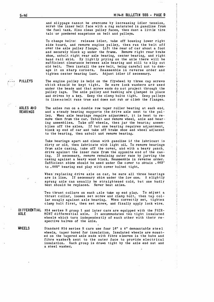
and slippage Gannet be overcome b y increasing idler tension, scrub the inner belt f ace with a rag saturated in gasoline f rom the fuel tank. Also clean pulley ,faces, then dust a litt le tire talc or powdered soapstone on belt and pulleys ..
To c h ange belts: release idler. take off housi.:lg lower right side b o ard, and remove engine p u l ley, then run the b e lt of! over the axle pulley f lange. Lift the rear of car about a :i!oot and securely block u_p under the frame� Remove right rear b rake shoe� unbolt right rear axle bearing, center bearing, and right hand rail skid� By li gh t ly prying on the ax le t here will be suf ficient clearance between axle bearing and sill to s lip out old belt. Then install the new belt, being carefu l not to damage it on s harp corners& Reassemble in reverse order and tighten center bearing last. Adj ust idler if necessary.
The engine p u l ley is held on the f lywheel by t hree. cap screws which s h ou ld be kept t i ght. Be s u re lock washers are used under t h e heads and that screw ends do not project through the pulley lugs. The axle pulley and bushing are glamped in place and driven by a key� Keep the clamp bolts tight. Keep pulleys in line so belt runs true and dces not rub or climb the f langes.
The axles run on a double row taper roller bea:r:ing at each end, and a s teady bearing supports t h e drive axle next to t h e pulley. �hen axle bearings require adjustment, it is best to remove them from t h e car. Unbolt and remove wheel� axle and bearing assemblies� Take off wheel$, then j ar the bearing assemb lies off t h e axles� If b u t one bearing requires adjustment, b lock up end of car and take off b rake shoe and wheel adjacent to the bearing, then unbolt and remove bearing ..
Take bearinss apart and clean with gasoline ii the lubricant is dirty or old, then lubricate with light oil. To remove bearings from axle casing, t.ake off the coverj and with a heavy punch, drive agains t the inner race �rom the opposite end o1. the casing� If necessary, remove remaining outer race by j arring t he ca:sing against a heavy wood b lock. Reassemble in reverse order. Sufficient s hims should be used under the c ovet to obtain • 00311
to .. 00511 b earing end play with cover bolted tight.
When replacing d rive axle on car, be sure all three bearings are in line. If necessary shim under the ,low one. A s ligh t ly sprung axle can usually be straigh tened coldJ b u t one badly bent should be replaced. Never heat ax les.
'Two t hrust collars on each axle tak.e up end p lay� To adj us t a. thrust c ollar, loosen set sc rew and clamp bolt, t h en tap collar snugly against axle bearing. When correc t ly set, tighten c lamp bolt first, then set screw, and finally apply lock wire.
M14 series H group 1 and later cars are equipped with the FAIRMONT differential axle. I t accommodates two t i g h t insulated wheel� which turn independently of each other with t h eir respective h a lves .of the axle.
Standard M14 series H cars use four 1 6 11 x 111 demountab-le s te e l wheels, taper bored for insulation. Insulated wheels are mounted on the tapered axle ends with fibre s leeves in t he h u b s and fibre washerS next to t h e outer !ace to provide elec t r i c a l insulation. Each group is drawn tight by the axle end nut and a steel washer ..
PAGE 10 - BUUETJN 555 M 14-H 5-46
WHEEL All GNMENT
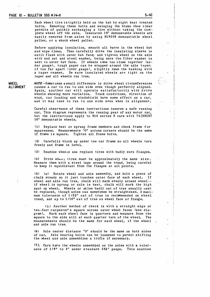
Each whee l tire i s tightly held on the hub b y e i g h t heat treated bolts. Removing these bolts and swinging the brake �hoe c lear permits of quickly exchanging a tire without taking the complete wheel off the axle. Insulated 1 6 n demountable wheels are ea,s i l y removed f rom axles b y u s i n g M19509 demounta.b le whe e l puller. o r a shock wheel puller.
Before applying i n s u la t i on, smooth all burrs in the wheel hub and wipe c lean. Then carefully drive the insulating s leeve in until f lu s h w i t h outer h u b face; and tighten wheel on the axle w i t h end nut and steel washer, b e ing sure t h e f iber -washer i s next to outer hub face. If wheels ccme too c lose together (under gaugel , tough paper can b e wrapped around the axle taper; i f too far apart ! over gauge ) , s lightly ream the b u s h i n g w i t h a taper reamer.. Be s u re i n s u lated w h e e ls arP t i g h t on t h e taper and all wheels run true.
NOTE---Scme'tJ.mes a small difference in drive wheel c i rcumferences causes a car to run t o one s i de even though perfectly aligned. �gain� a n o t h e r car w i l l operate s a t i s f ac to r i l y w i th d r ive wheels showing more variation. TTack conditions, direction of wind, c a r loading and windsh i e ld have some e f f e c t on a car, and i t may tend to run t o one s ide even when in a l i gnment.
Caref u l observance of these instruct i ons insures a safe running car. This diagram represents the running gear of any motor car, but the instructions apply to Ml4 series H cars with FAIRMONT 1 6 " demouatab le wheels.
Ill Replace bent or sprung frame members and check frame f or squareness. Measurements 11G11 across corners s h ould be t h e same if frame i s_ square. Tighten all f:tame bolts.
(2) Carefully block up under t.lle car frame so all wheels turn freely and frame is leveL
( 3 1 Examine wheeLs ana replace tires with badly worn f l anges�
14) Drive wh��L t i res must be appro�imately-the same s i z e . Measure them with a steel tape around the tread, being careful to keep it equidistant from the f langes at all points.
( 5 ) la I Rotate wheel and axle- assembly, and hold a piece of c halk steady so it j us t touches outer face of each wheel� I f wheel and axle run true, chalk w i l l mark evenly around wheel-if whee l is sprung or axle i s bent, chalk will mark the h i g h spot on wheel. Wheels or ax les badly out o f true usually must be replaced, though axles can sometimes be straightened. A max i mum tole rance o f 1 /3 2 " o u t o f true i s recommended on w h e e l tread, and u p to 1 / 1 6 " o u t o f true o n wheel face o r flang'e.
(b ) Another method of c h e c k is with a straight edge or two-foot c arpenter• s square across outer wheel faces (see diagraml J Mark e�ch whee l face in quarters and measure from the square to the side s i ll at each qUarter turn of the w h e e l. The measurements should be the same for each wheel, i f the whee l and axle i"un true.
161 Axle center distance "A" s hould be the same on both sides of car. Axle bearing bolts can be loosened to permit s h i fting the . wheel and axle assemblies a trifle if necessary.
17.!J Cars h av e the wheels assembled on the axles with a tolerance of 1 / 811 tO 4-" under s tandard 5 6 !n gauge. T h i s enables
5-46
BRAKE
M 1'1-H BULLETIN 555 - PAGE 1 1
I " A r� Z\c . cl � ""/ G G�
m V /
�/' c\
I
y
� "TO 'U . �A
�·� WHEEL YAAI\ED AT EACH QUtiJfi'[R FOR TRU£ RUNNING TEST (�) 1t
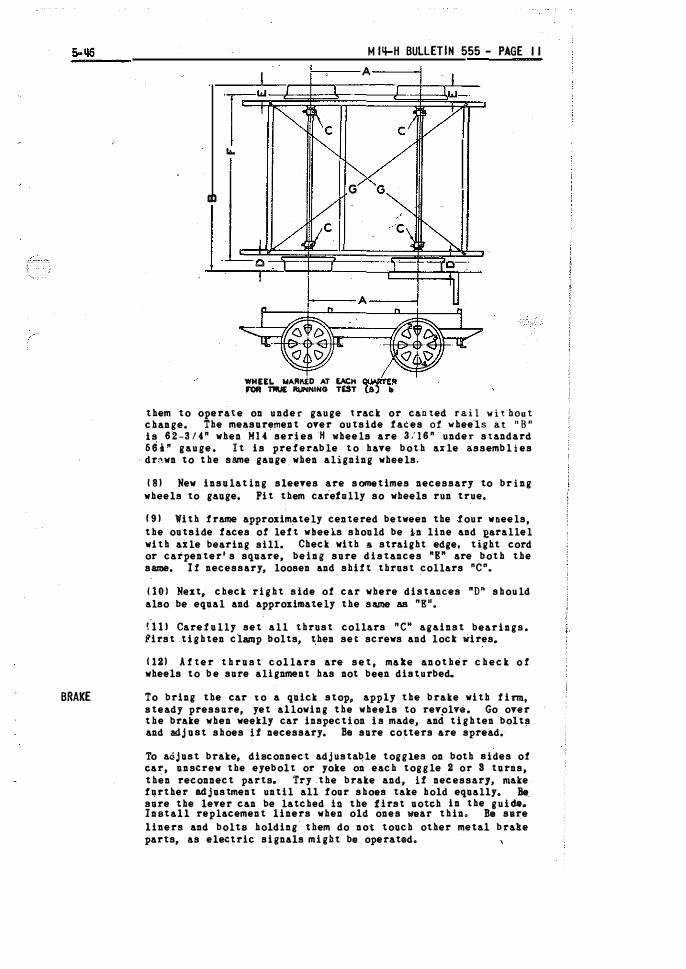
them to operate on under gauge track or caoted rail wit·hout change. The measurement over outside faces of whee-ls at "8" is 62-3/4" when M14 series H wheels are 3:16"-- under standard 56i" gauge. It is preferable to have both axle assemblies dr<".wn to the same gauge_ when aligning wheels.
181 New insulating sleeves are sometimes necessary to bring wheels to gauge. Fit them caiehlly so wheels run true.
(91 With frame approximately centered between the four wneels, the outsid.e faces of left wbeeis should be h line and J!&rallel with aXle bearing sill. Check with 11 straight edge, tight cord or carpenter's square, being sure distances "E" are both the same. If necessary, loosen and_ shift thrust collars "C".
1101 Next, check right side of car where distances "D" should also be equal and approximately the same as "E11�
!111 Carefully set all thrust collars "C" against bearings. fi'irs·t .tighten clamp bolts, then set screws and loct Wires ..
(121 After thrust collars are set, make another check o f wheels to· b e sure alignment has not been disturbed.
To bring the car �o a quick stop, apply the brake with fi�, steady pressure, yet allowing the wheels to revolve. Go over the brake when weekly car inspection is made, and tighten bolts and adj oat shoes U necessary. Be sure eo� ters are spread.
To adjust brake, disconnect adjustable toggles on both aides of ear, unscrew the eyebolt or yoke on each toggle 2 or S turns, then reconnect parts. Try _the brake and, U neCessary, niake further adjustment until all four shoes take hold equallye Be sure the lever can be latched iD the first uoteh in the guide. Install replacement liners when old ones wear thin� Be sure liners and bolts holding them do not touch other metal brake parts, as electric signals might be operatode
PAGE 12 - BULLET! H 555 MI q-H 8-51
COOLING SYSml
FUEL
SYSTEM
CAR FRAME
AND HOUSING
ENGINE ;l()UNT I NG
Use clean soft water in the cooling system if available. ·It is recommended that the rust preventative furnished be regularly used, except do not use with a .Permanen t anti-freeze. Keep wat·er up to the level of fi11er neck. Capacity is approximately Six quarts. In serv.ice, steam from boiling water rises to the condenser where it is condensed to water which drains back.
A motor car operated in severe cold weather maY cool too much, or the condenser may fill with frost, causing water to be forced out thru the overflow. To insure normal operation, partially or entirely c"()ver the front of the condenser with cardboard or canvas. Cars can stand in freezing- weather without harm to the jacket, prov'iding water is not carried above the proper level. If cooling system contents freeze solid, be sure eng-ine is thOroughly warmed up before driving car.
Automobile anti-freeze mixtures which contain mineral salts should not be used. Mixtures of alcohol and water give fair satisfaction in severe weather, providing the condenser is- not covered, Equal parts of water and "Zerex1', or "Prestone" make a satiSfactory anti-freeze, providinQ" the condenser is protected to prevent frost forming inside. Always use water to replenish any loss by evaporation.
After long service, lime and scale deposits from the water may cause overheating, These can be scraped off the cylinder walls after removing water hopper and cylinder head.
Inspect the fuel system regularly and see that the tank is securely h-"eld by the tank straps. At least onc·e a_ year remove the tank from the car a n d thoroughly flush it out to remove sediment, water, and lint, The F3613 gas tank cap has an ai-r
_ vent to allow free flow of fuel to the_carburet0r. Never use F5115 condenser cap on the gas tank as it has no vent, Loops and bends in the fuel pipe sometimes cause "air locks" which prevent the flow of gasoline. Blowing in the tank will start the flow if fuel pipe is not clogged.
All strainer bowls should be taken off and cleaned at least once a month, oftener in winter. Be sure gaskets are in good condition when replacing bowl.
Keep all frame bolts tight. In case frame members become damaged, straighten them; or if badly out of shape, replace. Unlatching and removing the seat top permits inspections and adjustments to be quickly and easily made.
The engine is held on the engine sills by four 7/16'' bolts with nuts and lock washers. They should be ke_pt tight.
HOII ENGINE OPERATES
BATTERY IGNITION
M 14-H BULLET! N 555 - PAGE 13
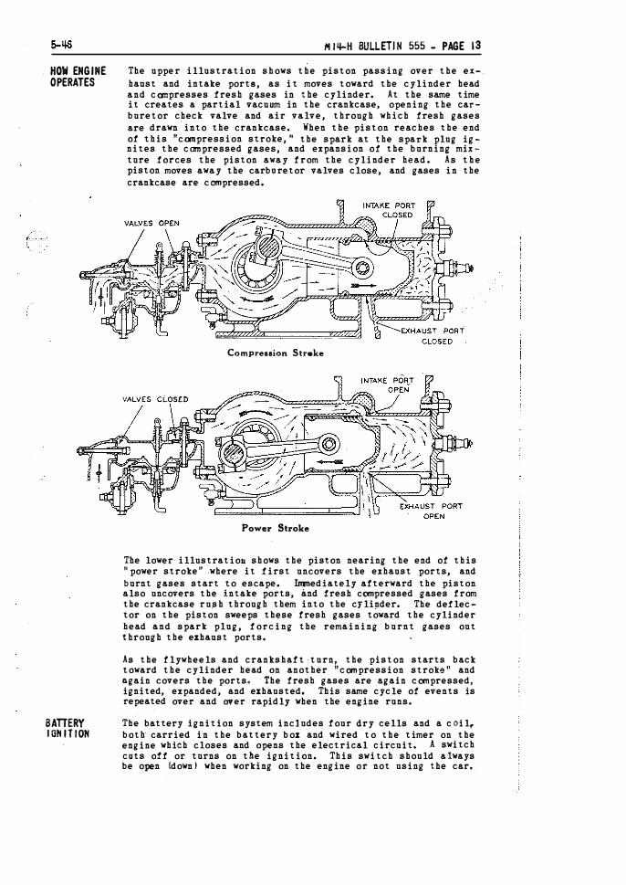
The uppe_r illustration shows the piston passing over the exhaust and intake porta, as it moves toward the cylinder head and compresses fresh gases in the cylinder. At the same time it creates a partial vacuum in the crankcase, opening the carburetor check valve and air valve, through which fresh gases are drawn into the crankcase. When the piston reaches the end of this "compression stroke, 11 the spark at the spat'k plug ignites the compressed gases, and -expansion of the burning mixture forces the piston away from the cylinder head. As the piston moves away the carboretor valves close, and gases in the crankcase are compressed.
Compression Streke
Power Stroke
The lower illustratiou shows the piston nearing the end of this 11power stroke" where it first uncovers the exhaust ports, and burnt gases start to escape. Inrnediately af'terward the piston also uncovers the intake ports, and fresh compressed gases from the crankcase rush through them into the cylinder. The deflector on the piston sweeps these fresh gases toward the cylinder head and spark plug, forcing the remaining burnt gases out through the exhaust ports.
As the flywheels and crankshaft turn, the piston starts back toward the cylinder head on another 11canpression stroke" and again covers the ports. The fresh gases are again compressed, ignited, expanded, and exhausted. This same cycle of events is repeated over and aver rapidly when the engine runs.
The battery ignition system includes four dry cells and a coil,. both carried in the battery box and wired to the timer on the engine which closes and opens the electrical circuit. A switch cuts o!f or turns on the ignition. This switch should always be open {downJ when working on the engine or not using the car.

PAGE I � - BULLETIN 555 M I4-H 8-51
SPARK COIL
SPARK P LUG
An engine which misses when cold and first started will usually fire regularly after being warmed up. Eefore changing ignition, warm up engine and try different carburetor adjustments. Then if ignition is suspected, check all wiring, switch, and connections. Tighten coil connections lightly.
New dry cells test 3D to-
35 amps each anri are good for several months, or until exhausted to 8 or 10 ;:vnps. Then replace entire set. Freezing reduces thr::ir efficiency, necessitating more frequent replacement in cold weather. Keep inside of battery box dry; cardboard cases on dry cell.s; dry cells finnly wedged in place so connections do not toucb each other; and wiring f ree from oil, gasoli-ne, and water.
The switch or ''ground '' wire pf dry cell ignition systems attaches to upper or blade co.nnector Ill, and "live" wire to insulated contact screw connector (2). The timer blade is grounded through the clamp blHck 57312, always connects to t h i s terminal 11). gram below.
i:l.nd "ground'' Se:e w-iring
1v ire dia-
Cars With generator and storage battery have one side of the electrical system iJermanently grounded. Then the coil, switch, and wiring connect to the insulated contact screw and are in the "live" side of circuit. See wiring diagram in generator and lighting equipment bulletin.
Always keep spark coil dry, and rrse only four dry eel ls. If system is in good condition, a 1/4" to 5/16" spark should jur1p from end of high tension- cable to engine. If not, vibrator points may require attention or a new coil n•ay be necessary. When rough or pitted, dress the alloy vibrator ooint� clean &nd s:nooth with a fine file, pocket stone or emery cloth. After they wear thin, fit a complete new vibrator F4166 tu the coil. See that points match and seat together evPnly at all tiflles, and that the point opening is 1132n.
To check current draw of coil, use an accurate low reading anmeter (Fairmont F7838). Remove spark plng and lay it on some metal frame 11,ember, or disconnect high tension cable and holrl it about 1/8" froP• engine. Close ignition switci• and turn fly-wheels until timer points· close and cause coil to buzz. Open s1vitch, then hold alru•Jeter !earls firmly against switch binding posts. With good batteries the current draw should be .85 to .90 amps. Adjust coil draw by carefully bending the farthest
end of vibrating point bridge down toward coil box to iitcrease the current, or up to reduce the current, as required.
To test, remove from engine and lay on some metallic part of car or engine, high tension cable attached. Close (pull upl switch and turn engine until the coil buzzes. If spark at plug gap is not steady, check high tension cable and clean the plug,

8-51
T IMER ADJUSTABLE WEATHERSEALD
M I �-H BULLET I N 555 - PAGE I �A
then test again. If condition of plug is doubtful, replace plug. Set points at 1/32" gap for battery ignition and 1/64" for magneto ignition. Check and reset gap wher,ever plug is removed. Always carry a spare plug for emergency use. Replacement plugs should duplicate the factory plug cloSely and be 18 mm size, also keep tight with gasket fully compressed,
The Fairmont Adjustable Weatherseald Timer uses the standard A595 double leaf spring blade and has contact points enclosed in the mounting casting to prevent entrance of moisture, oil, and foreign matter. This timer i s used on RO-C battery ignition engines numbered 88480 and higher. It i s also applicable to earlier RO-C units.
The interval during which the ti�er points close to produce the spark should be 30° to 35°, or about one tenth of a ·flywheel revolution. This measures 5" to 5-112" for RO-C engines wi�th 1811 flywheels. To check this n:ea •1rement, close switch and slowly turn flywheel until contact po ints just close, causing coil to buzz. Mark flywheel rim in line with timer handle or some fixed object. Again turn flywheel in san1e direction until coil just stops buzzing and mark flywheel as before. If adjustment is necessary turn arc adjusting screw 57314 to right to increase the interval and to the left to decrease it. CAUTION--Do not attempt to adjust timer l'iith engine running.
Best ignition is obtained with the contact points adjusted with .020" to .030" opening. Following is an easy way to set them. Remove timer body from mounting casting by releasing arc adjusting screw 57314. Loosen lock nut on point adjusting screw PB-17G, Turn this screw down until the two :POints just touch, then back screw out a scant 1/2 turn and tighten the lock nut. Check with feeler gauge if one is available.
DO N OT ADJUST TIMER POINTS TO CHANGE THE LENGTH OF CONTACT-keep them set at ,020'' to ,030'1 opening.
If the points burn or wear unevenly, dress them with a fine file, pocket stone, or fine emery cloth. Be sure they match and seat together evenly when adjusted. Kef? timer con-nections clean and tight. The mounting -Casting should be
0

PAGE 1 48 - BULLETIN 5 5 5 MI 4-H B- 5 1
adjUsted closely on support casting, yet be f ree t o move when spark is ''advanced" or ' 'retarded''.
To renew t i mer blade, remove b o dy assembly f rom moun t i n g c a s t i n g , and loosen c l amp s c rew F2859. Be c a re f u l n-o t t o lose -PB-17T spri ng. Reassemble w i t h new parts, mak i n g sure clamp block is c lean to insure good connection; also lined w i t h blade a n d rounded e n d towards t h e p a i n ts, and· t h a t t he two contact points match and seat together evenly. Adjust points f r om .02011 to .03011 and reassemble on moun t i n g cas t i n g, then adjus t for proper contact interval as explained previously.
The nylon t i mer wiping block 57318 can be quickly and eas i l y replaced a s f ollows: Remove complete t i mer f r om s u p p o r t c a s t i n g . W i t h a pair o f pliers opened w i d e grasp t he w i p i n g block a s s h own. Apply p ressure on pliers, at t he same t ime tilt pliers either up or down. This will release wiping block f r om one l i p of cam sleeve and permit remov al.
Use ·pliers_ to install new w iping block, placing one edge under sleeve lip, then apply just enough pressure to clear other l ip o f cam sleeve. The w i p i n g block tends to s t ra i g h ten out, caus i n g it to lock snugly i n t he cam sleeve. Center wiping block under t imer blade and app l y a t h i n coat o f grease. Adjust points, reassemble t ime r on support cas t i ng, and reset c on t a c t i n terval.
The sponge rubber gasket 57311 seals the t imer f rom water, snow, and fore i g n matter. When applying a new gasket' f irst clean t imer body - then moisten adhesive s i de o f gasket w i t h gasoline and press i n t o place.
Always check and readjust point opening, and length of contact interval, after making any repairs or removing timer parts from engine.
8-51
WEATHERSEALD TIMER (NONADJUSTABLE)
F
M I�-H BULLET IN 555 - PAGE 1 5
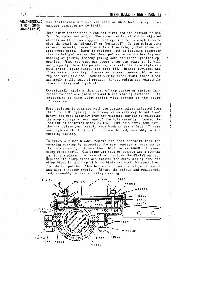
T h e Weat h e r s e a ld Time r was u s e d on RO-C b a t t e r y i g n i t i on engines numbered u p tO 8 8 4 80.
Keep t imer connections clean and t i g h t and t h e contact _points free from pits and scale. The timer casting should be adjusted closely on t he timer support casting, yet free enough t o move when the spar_k is 11advanced11 or "retarded". If the points burn or wear unevenly, dress them with a fine file, pocket s t one, or f i ne emery cloth. Timer is equ ipped with an ignition c ondenser that is bridged across t h e timer points to reduce burning and scaling of points, thereby giving more effic ient i g n i t i o n operation. When t h e cast one piece t imer cam wears so it w i l l not properly close the p o i n t s replace w i t h t h e late s t y l e cam w i t h nylon wiping block, s e e page 14B. Remove flywheel and timer support cas t i ng. Loosen set s c rew, remove old earn and replace w i t h new one. Center wiping block under t imer blade and apply a thin coat of grease. Adjust points and reassemble timer casting and f lywheel.
Occasionally apply a t h i n coat o f cup grease or s imilar lubricant t o cast one piece cam and blade wearing surfaces. The f r e qu e n c y o f t h i s l u b r i c a t i on w i l l depend on t h e h o u rs of s e rv i c e .
Best i gn i tion i s obtained w i t h the contact points adj usted from . 020n to . 03011 opening. Following i s an easy way to set them: Remove the body assembly from the mounting casting by releasing the _snap springs at each end of the body assembly. Loosen the lock nut on adjusting screw PB-17G. Turn t h i s screw down unt i l t h e two points j us t t o u c h, t hen back i t o u t a f u l l 1 1 2 t u rn and t i g h ten t he lock nu t. Reassemble body assembly on t h e mounting casting.
To renew a t imer b lade, remove t he body assembly from t he mounting casting by releasing the snap springs at each end of t h e body assembly. Loosen t imer blade s c rew 4 5 5 6 2 and remove clamp block 45561. Old blade can then be removed and a new one put i n i t s p l ace. Be careful not to lose the- PB-17T s p r i ng. Replace the clamp block and t i g hten t h e screw making sure the clamp block i s lined up with the blade and with the rounded end towards the points. Also be sure the two contact points match and seat together evenly. Adj u s t the p o i n�s and reassemble body a s s embly on t h e mount ing c a s t i ng.
7512 F4761
45550
562
244Z
5558
0 0
PAGE 1 6 - BULLET IN 555 MI �-H 8-51
CARBURETOR
AIR CLEANER
CONNECTING ROD
The carburetor control knob turns to open or close the needle valve and pulls up to choke the carburetor. If needle valve is opened too far the mixture will be "rich". Black smoke from the exhaust indicates a "rich'' mixture, With needle valve closed too much the mixture is "lean11• A "lean" mixture gives a weak explosion and causes engine to run unevenly, missing a few explosions or back firing. L may also cause ove:r-hea:ing,
The needle valve should ah;ays be set so the engine runs best with the least gasoline. The best adjustment for a �><arm engine is between 1 and h tu!'ns open, \•ihen starting in cold weather, open needle valve at least a turn more than the regular adjust� ment. After engine is warmed up, needle valve can be closed to the regular adjustment. Don1 t close needle valve \fhen stopping engine, nor shut it hard. Springs on check and air valves are set with correct tension at factory and should not be changerl.
<Sometimes a hot engine will start hard after standing a short time. This is caused by "flooding", or a very rich mixture forming in the crankcase. A "flooded" engine can be cleaned out by opening crankcase drain cock and rocking flywheels.
The small vent hole in body of carburetor should be kept open. If gasoline runs out, or constantly drips, float valve is not seating properly. To remedy, take off and clean strainer bowl and drain carburetor, then replace parts. If float valve continues to leak, shut off gasoline, remove float bowl, and inspect float valve, float lever bearing and hinge piu. Nev. parts should be applied -if these are badly worn, and float level checked.
\ith float lifted to its high position and float valve tight on the seat, the top surface of float should be 3/8 to 7/16 inch below top rim of bowl. If the distance is less than t!lis, the float valve and seat should be renewed. The strainer bO'Iil should be taken off and cleaned regularly,
Cars are equipped with open screen type of air cleaners as standard. Clean the screen every two to four weeks, depend irrg on conditions. Extremes may necessitate other intervals. To clean, remove screen assembly and wash in gasoline or engine fuel mixture. Allow screen to dry thoroughly, then dip in medium engine oil, .drain and replace.
The piston pin bushing is pressed in the connecting rod, and reamed for . 0015" to . 002" clearance on the pin. The renewable bearing halves at the crankpin end wear slightly in service and need occasional adjustment.
The connecting rod should be fitted ,002" to .00:-:l" loose on the crankpin. To adjust a loose rod, remove carburetor. Remove lock wire, both cap screws, cap, and shims. Peel off one or more layers from each shim, according to looseness; then replace cap and shims, drawing screws tight, and test adjustment. If still loose, continue until correct. Do not file the cap or rod body. There should - be very little play in this bearing. If piston rebounds from compression the bearing is not too tight. Be sure screws are tight, then lock with a new wire.
The two halves of the crank pin bearing are renewable, and should be replaced when worn to a point where all shims have
5-'16
AWMINUM ALLOY PISTON AND RINGS
FLYlllfEELS
ROLLER BEARINGS
CRANKSHAFT AND ROLLER BEARINGS
I� 1'1-H BULLETIN 555 - PAGE 17
The two halves of the crank pin bushing are renewable, and should be replaced when worn to a point where all shims have been removed. The buShing half for the rod body is plain, and the one for the cap is drilled and has oil grooves.
New rings should have -an end opening of • 011" to . OlSif. To remove a piston pin from·a piston and rod assembly, first take out lock rings, then heat piston bead in boiling water, and push or care�nlly tap pin out. To assemble, insert one lock ring in piston. Thoroughly heat piston in boiling water, hold connecting rod in place, and quickly push in the cold# pin :o.ntil it stops against the lock ring. Finally install -the remaining lock ring and check piston for roundness. The piston pin should not ,be forced into a cold piston. The boles in the pistGn pin bosses should not be enlarged.
To pull piston from cylinder, first remove carburetor, then disconnect connecting rod. Remove cylinder head, after which piston and rod can be pulled. When replacing piston, be sure the deflector is in proper position (see cut on page 13)� The piston Rin and holes in the piston and connecting rod are finished to insure assembly without fitting. Always use a new pin with a new piston.
Flywheels are locate� on crankshaft tapers by keys, and draWn to place by nuts. Don't try to drive flywheels off as spokes are liable to be cracked, crankshaft sprung, or bearings damaged. To remove a flywheel, pull cotter and unscrew nut. With a brass or lead hammer weighing about 3 lbs. sharply strike end of crankshaft, a.t same time pulling outward on flywheel r'im. Flywheels which have been in place a long time may stick, and a jaw wheel puller should be used. When replacing flywheel, wipe parts clean and oil, draw nu� fairly tight and insert cotter.
Roller bearing installations on -FAIRMONT ·equipment are approved by the bearing manufacturer's engineers, and bearings have proper load capacities and- clearances to insUre satisfactory service� Don't strike bearings with steel hammers. Always drive them off evenly with a brass punch held against inner races only, being careful not to damage the roller retainers. A piece of clean tubing which just slips over the shaft is best to_drive them back in place. Never lay bearings on work benches or heat with a torch. Wash in gasoline or hot soda bath as soon as removed, lubricate with oil, and wrap in clean paper or cloth.
The crank pin, inboard roller bearings and outboard roller bearings are lubricated by oil which enters the crankcase mixed in the fuel,
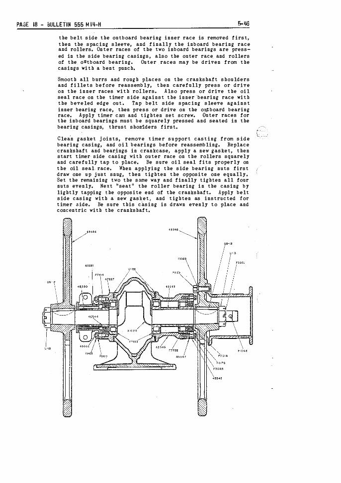
To remove crankshaft disconnect connecting rod, then push piston and rod assembly toward cylinder head. Take off flywheels and remove starting crank pin from crankshaft. Remove nuts holding side bearing casings and carefully drive t&em off with a block of wood. Remove timer cam and key, turn crank pin straight down in crankcase, then lift out crankshaft with bearings.
The three roller bearing races are pressed on the cranksheft, the inner two having rollers and cages asse!'Jbled on them. If .necessary to remove them, they should be driven off evenly, with a bra.cs punch against inner races onlY. The oil seal race on timer side is forced off as the bearing race is removed. On
PAGE 18 - BULLETIN 555 M 111-H
the belt side the outboard bearing inner race is removed first, then the spacing sleeve, and finally the inboard bearing race and rollers. Onter races of the two inboard bearings are pressed in the side bearing casings, also the outer race and rollers of the oUtboard bearing. Outer races may be driven from the casings with a bent punch.
Smooth all burrs and rough places on the crankshaft shoulders and fillets before reassembly, then carefully press or drive on the inner races with rollerso Also press or drive the oil seal race on the timer side against the inner bearing race with the beveled edge outa Tap belt side spacing sleeve against inner bearing race, then press or drive on the ou;tboard bearing race. Apply timer cam and tighten set screwo Outer races for the inboard bearings must be squarely pressed and seated in the bearing casings, thrust shon1.ders first.
Clean gasket joints, remove timer support casting from side bearing casing, and oil bearings before reassemblingo Replace crankshaft and bearings in crankcase, apply a new gasket, then start timer side casing with outer race on the rollers squarely and carefully tap to place. Be sure oil seal fits properly on the oil seal race. When applying the side bearing nuts first draw one up just snug, then tighten the opposite one equally. Set the remaining two the same way and finally tighten all four nuts evenly. Next 11seat11 the roller bearing in the casing by lightly tapping the opposite end of the crankshafto Apply belt side casing with a new gasket, and tighten as instructed :for timer aide. Be sure this casing is drawn evenly to place and concentric with the crankshaft.
8-51
THROTTLE
CARBON DEPOS I TS
CYL I NDER HEAD
MI �-H BULLETIN 555 - PAGE 1 9
The crankshaft and bearing assembly must have 1 / 6 4 " to 3 / 6 4 " clearance when side bearing casings are bolted i n place. Check this by tapp ing crankshaft on one end� then the other, and measure the amount i t shifts. An extra gasket may have to be added at one or both bearing casings to secure clearance. Replace belt side bearing casing cover, using a new gasket, and be sure oil seal is in good condition. On the timer side, replace th.e timer support casting on the side bearing casing, with the open ing for timer blade towards carburetor end of eng ine. Flywheels and rema ining parts can then be reassembled.
Leakage at the throttle stem is p revented by a packing. The stop in opposite cover limits the valve travel. The throttle arm is h e ld in place by a clamp screw that should be kept tight. If this arm slips, the throttle may not open properly� The throttle valve can be pulled out ftom belt side of engine after removing valve cover.
After long service the p iston head, inside of cylinder head, and walls o f combustion chamber become coated w i th carbon. Knocking or "pinging11 then occur wheti the engine is wanned up, especially when pulling loads. Carbon can be scraped out after removing cylinder head. Clean the intake and exhaust p orts; removing the muffler and throttle valve makes it easier. Carbon inside the piston head and deflector should also be removed. Wipe or blow out loose carbon before reassembling.
Carb�n gradually forms in the p iston rings to stick and engine to overh eat. oughly clean rings and grooves.
r i n g grooves, causing Pull p iston and thor-
When replacing cylinder head, be sure the gasket is in good condition and joints are clean. First tighten every other cy linder head nut just snug, then set the remainder the same way-. Next, go over all of them, tightening to p lace evenly. Occasionally check cylinder head nuts with a wrench and tighten firmly.

I I
PAGE 20 - BULLET I N 55& M 1 4-H 5 - '16
I N STRUCTI ONS FOR ORDERI N G PARTS
When t h i s b u l le t i n is received, complete t h e f ollowing motor car record f r om t h e FAIRMONT name plates on the car and on the engine water hopper. The eng ine num!>er i s also stamped on top of the crankcase. Always me n t i on t hese factory serial numbers when w r i t in g about the car or ordering parts.
Factory Car No. ------- Class ________ series _________ _
Group ________ special ________ _
Factory Engine No. _____ _ H. P. ______ Type -------
Group ________ spec ial _______ _
TO I N SURE PRO.�PT AND CORRECT SH I PMENT of parts, a lways give: ! l l Quan t i t y of each part wanted. ( 2 ) Symb ol numbB r o f part as s h own i n this book. ( 3 ) Description of part as s h own in this b ook. ( 4 1 Factory serial numbers recorded above. (5) Car gauge i f other than 56P standard. ( 6 ) State whether shipment is to be by mail, express� or freight.
A l l parts are s hipped f. o. b. factory, transportation charges to be paid by custcrner. Terms are stric tly cash with order.
Parts are l is ted by des c r i p t i on, symbol and quanti ty, and a l l important items are i llustrated. Quantit ies in right -hand c o lumns show t_be number of parts in each assembly or group. Items printed in capitals are assemblies w h i c h include a l l parts listed immed iately f ol l owing and indented to t h e r i g h t� When assemb lies can b e used, a lways order them to s ave work o f f i t ting separate parts. I f in doubt a s t o any part wanted, send f u l l description -or sketch, or send old part with order.
For desc ri ptive pu rposes the engine end of car is named front, and r i g h t and left are determined by looking from rear to front.
Conmon bolts� nuts and washers are not listed in this bulletin, as they can be obtained f rom any rai lroad s tore department.
T h e w e i g h t and nume r i c a l par t l i s t on pages 21 t h r ou g h 23 containS a l l i tems sh own i n t h e parts s e c t i on covering standard d irect belt drive battery ignition cars. Spare parts for accessories, and parts used on special cars only* are not listed in t h is index.
Spare part s of accessory groups are g i ven on pages 4R t hrough 50. Items u s ed only on c ars having f i g u res in t h e space on the name plate marked " S pec i a l " are listed according to car desi gnat i on, start ing on page 52.
CAR I DENTI FI CATION { Found on Car Name Plate )
To accurately iden t i f y cars, all units carry t he designat ion "Class M U - -S eries H--Group ____ --Special ____ . " The group numbe r is always s h own, and cars having changes t o cust aners1 spec i f i c a t i ons also have f i gures in t h e s pace marked 11Special. 11 When t h e letter " Z " appears i n the designation, i t indicates ei ther broad or narrow gange.

M ! �-H BULLETIN 555 - PAGE 20A
ESTIMAT I NG P R I C E L I ST
This list covers all parts in H14 Series H car bulletin 555 as of September 15, 1954, and shown in NUMERICAL CHECKING LIST on pages 21, 22 and 23, The p r i � e s are for estimating purposes only in t h e United States, They are i s sued for convenience in preparing requis i t ions and estimating repair costs� A reasonable amount has been added to these prices to cover trans� portat ion, so that they can be considered as approximate costs of the parts L Oo b dest i�a�ion in t.h e United S t a t e s .
RO"-C-- � , . -L··lE • .
QE�1 2 • • . . •
U-·15E . " PB�HG . . . . PB .. 17T . . QH .. 21A P-21D D .. 47D . c .. 48 n .. <sA. TF·-68F', PH 90F.
: H102.
I. A406 A408. A 409.
. A410 . . .
I ��!:!: . I ��!:�·. , I EZ474. I A 524 i EZ530 . 1 E Z540_ � .
! EZ 54L . i A.544. -
I A545 . . I A547
. ! A554, ! A5950 , I AM6. ./· .4692 .
A695, , 1 F 1000.
I F 1 007. p1009.
I F l OlL F '023o A\025. 1 F 1025
I F1040. 11 Fl048. , F1081 . _
F1103 � . . 1 -�111�, , -I
AHl,. . F l 125: . .
I Al127A . I A 1 1 28 • o
I F1222. 11 A1241 • .
F 1 291. . 1 _ A 1 318, .
231 00 A 1 326 • •
.81 A 1 327 • • . .
, 34 A133L . . . -10 A 1 332 • .
, 54 A 1 334._ . . 1 8 1
·
!1341 . • .
1 . 4 5 A 1 34'L , _.
. 09 Al349 . . , 1 4 1 H 350o , . . •
l 3 1.
A 1 B 5 L . _ '18 A1353.
34 1 A1354 . •
. 4 5 j A1256A. � 2 9 I A 1 357. >
..
1
.
8 1 A13590 . . . 8 5 A\3610 • •
1 . 1 5 A1362 . 61 j Al364. .. 0
.
8 1 Al366 . . 33 A 136'L
1 .40 I
A 1 368, . . 39 A 1 369A.
06 ! A 1 37i-30 ! !1375. '
. 6 8 1 A1384. _
• 08
.
!1386 . . .08 Al 387 . . , 1 1 A1388.
35 A1389, . . 1 8 A1 394, . . 2 1 A 1 398,
l 25 1 Al 399. 23 ! F1402 . ft.
s 65 •1 F'145L _
1 00 F l 493 . . 02 F l 649 . . 0 3 1 F 1 688 . 07 1 F 1 692, , . 01 F l 702 . ,
1 i)O I F 1 74 1 , . 36 50 F 1 903. .
01 I F \9690 . . 02 I F 1 97L .
' 1 1 I H2314_. ' '11 F 2442, 02 I F 2447
14. 65 F 2492. 12 95 F 2493.
.04 F 2551 28 90 F 2581.
8 15 F 2 608 . . . 06 F 2702 . . , 1 5 F 2703, . . 02 F2723 . .
32 , 7 5 i F 2737_ " . ,
, 0 8 1 F2753, o 1 , 35 F 2'l66" .
, 94 F283L . , . 0'1 F2859 . .
! . 05 F2866 . . 4 6 F2877 . .
. 8 6 , F293l . .
. 34 F 2945. 74 F2946.
14 05 F2948. ,'73 F2958, , f -t:�
L �5 F 3006, _ it 1 AO F 301L . 1 1 5 F 3029 1 25 F 3030 . .
. 34 F 3032. 5 85 F 3054 • . f t .
, 1 8 F3132" 07 F 31 57. , . 4 3
L 4 5 1 . 8 5
1 1 6 5 1 3 . 95
, 6 1 8 6
6 5 5 1 5 7 5
. 85 17 70
35 2 1 0
, 1 9 0 2 03
. 06
. 1 4
. 01 04
1 1 5 , 0 2
01 02
. 1 5 0 1 1
. 08 1
. 04
. 0 3 . 02 1
. 02 02
,04 34 02 03
F3393 F 3450 F 3503. F3613 F3614, F 3 6 5l . . 0 .
F3718 . . F 3849. � . . F 3853 F3854 F 3855 F 4026 . . f t F4125 . . . F4166 F4178o . , F 4216, F4252 . F4314 . . F 437L F4413, H4442, M4447. F4635 . . F4734 . . F4761 F4770 F 51 1 5. F5-158 F 5 1 93 . . F fi.235 . F 5484 F 5493 . . F5603_ F 5652 . . F6470, F641 L ,
09 1 F 6 537 . . , , 19 90 }16540. ' . , '
03 F 6 584 • • , • .
03 F 6650 • . • • ,
01 M6738. . 0 3 F7013 . • , , .
. 01 F7020 . . . . .
. 77 F7022, . ,
. 6 6 F'll06. , . • .
. 44 F7119. , 08 F '/129 • . '
" 20 F '712L . . 31 F7244 . . . . .
07 I F7339 . . . 04 F7351. . 0 9 F7370 . .
03 F7387. . 31 F7455.
1 2 . 0 5 1 F'7506 . . 06 F7512 • .
10 H7556, . 03 F7808 •
80 F761L . 36 F7614. , ,
29 F7618 . . . . . 06 M7677D . • • .
22. 95 F7702, , . 1 7 F7760 . . . . . .40 F '/762. , ft, 2 0 F7792.
1 2 5 F7868 . . 2 55 F7876 . .
. 52 F7877 . . 02 F 7901.
3 00 F7923, . 10 F7926. . , 10 F7950, , , . ,
1 1 F 7953 .. 1 75 F7954. , _
.. 12 F 7955 . . . . .
. 1 2 F7956, . 07 F7957 . .
. 12 F7979 .. . . � 1 4 F7996, _
. 28 F800Z; 1 5-5 F803'L . ,
- 1 8 F 8 0 39, o 2 0 F8085 . • •
20 F808& . . . . 1 05 M&509. 6 62 M851 0, . ,
72 F 8692 . . 44 F 9 1 8 2 • . .
, 0 1 F9217, . . 03 I F923l,
. 01 ' 1 9 0 57 , 0 &
2 2 8 80
, 0 2 . 0 1
1 . 60 02
.02 03
. 31 35
1 . 50 06
. 1 3 91
. 07
.70 3 50 '
, 2 1 1 . 88
1 - 1 5 1 2
1 2 . 2 o I 1 1 1 03 45
5 40 . 8 3 . 29 .. 21 , i l
2 , 40 ' 08 . 1 8
2 . 70 1 . 95 1 50 L OO
. 8 3 31
6 50 ' 04 - 4 4
6 1 6 1
. 33 1 . 05
' 94 . 28 . 29 _ 1 8 _ 33 i

PAGE 208 - BULLETIN 555· Ml'li-H
F9256. o . o o . 0 4 M27808o • • • . 6 8 M33222 . . . . 1 . 7 5 45575 . . . . . . 17 F9448 • • . • • , 63 M2781 0 • • , . • 97 M33398 • • • • 1 . 55 45686 • • • . • . 1 2 10069 . . . . . , 3 6 M27894 • • • • L 2 5 M33435 • • o . . 97 45687 • • • • 0 . 1 2 F10535 • • • • . 06 M27895 . . . . L 2 5 M33789A . • • 4 . 8 5 46785, • • • • 1 . 05 F10536 • • • • . 0 1 M27896. , • • 3 1 . 3 5 M33953. , • • 2 . 65 47222 . . ' ' . 6 4 . 3 0 Fl0601. . . . . 0 4 M27897 . . . . 3 . 5 0 M34410 . . . . 2 o 4 0 47223 . . ' . . 5 5 . 7 6 Mll405 . . . . 8 . 0 5 M27898, , , . 3 . 5 0 M34595N • • , 1 2 . 95 47224 . . . . . 6 0 . 4 0 M1 1 4 1 0 . . . . 3 . 3 5 M27899 . • • • . 3 4 M34682. o . . . 4 0 47226 . . . . . 6 4 . 5 5 M11479, . . o . 13 M27905, . • o 1 . 5 5 M34740. , . . 7 . 4 5 47227. ' ' . • 8 . 7 0 M12024 . . . . . 22 M27907 • . • , 1 . 5 5 !134742 . . • • 3 . 7 0 47228 . • • • • 2 . 8 6 M12177 . . . . . 83 M27913; • • , 1 . 1 5 M34744 • • . • 7 . 4 5 48716 . . . . . 1 6 . 80 Hl2335 • • • • . 2 9 M2791 4. . • • 1 . 1 5 M35062. , • • . 94 48717 . . . . . 9 . 5 5 M12336, • • , . 1 7 M28351 . . , 1 . 4 5 M35511 . . . . 1 . 1 0 48718 . . . . . 18 , 1 6 M12376, . • • , 3 9 M28356. , • • 2 . 5 0 M35567 • • , . 6 . 2 5 48796 . . . . . 27 . 90 M13373 • • . . • 95 M28545 • • • • . 73 }!3 5598 • • . . 6 . 2 5 48797 • • • • ' 1 L 1 0 Ml5066, . , , 9 . 90 M28761 • • • , . 53 M3573!A . . . 3 9 . 6 5 48798, . . . . 7 ' 90 M15225 • • • • 2 . 05 M28762. , , , 2 . 6 5 M3573ZA. , . 1 2 A O 48868 • • • ' . 5 , 80 M15226, • • , . 45 M28931 • • • . , 6 3 M35733 • . • . . 61 48869 . . . . ' L 4 5 M15340A. , 1 L 1 0 M29229, . , , 2 . 8 5 M35'l34 . • • . . 5 0 48870, . ' • • 2 . 1 0 M15343A . • . 2 . 6 5 M29630A . . . 2 . 1 0 M35751 . . . . 1 . 2 5 49940, . ' ' . . 2 9 M15351N . . , 7 . 00 M29673" . . " 1 0 5 . 6 0 M35798N.. . . 1 2 . 9& 50627, « . , . 4 5 M16102 . . , 5 . 2 5 M29674, , , , 6 . 3 5 M36331·A; , 3 . 3 0 51140, . " ' L 4 5 !!16103, . . , 4 . 7 0 M29675, , . , 6 . 2 0 !!3 6389, ' " ' . 7 9 5 1 1 4 1 • • • . • 7 . 3 5 M16104. , . , 4 . 80 M29676, , , , 3 . 1 5 M36399 • . 5 . 40 51860. ' , 9 7 M16397, . , . 5 5 M29677. , , . 3 . 1 5 M36400, . . , 1 . 1 5 51937, . . , . 3 2 . 20 M16468 . . , . 32 M29678, . , . 3 . 3 0 113 6406, , ' , . 4 5 51943 . . . , , 1 7 . 7 0 M\6718, , . , 8 95 M29679, • • , 1 5 . 4 0 !136601, , , ' , 1 1 51 944, • • • . L OO M16725. , . . 5 9 M29680, . , . 1 5 . 40 }!3 6639, ' . , 1 . 1 5 5 1 945, ' . , , 1 8 M167 27, . , , 1 75 M29681, • • • 2 . 85 M36671, , , , 8 . 45 55494 . . ' . ' 1 2 . 95 }!1 6730, . • , 1 . 20 M29682. 2 . 85 • M36865. , • . . 1 8 55495, ' ' • . 1 4 . 6 5 M17193 . . , 1 . 8 5 M29685, • • , 1 . 50 . M�6866, , . , 29 55627 . . . • . , 15 M17647 • . , . 1 8 M29687, , . , ,, 74 }!36867 . . " . 2 9 56246 • . ' . , 2 . 1 5 }!1 8043 . . " . 1 5 M29688, • • , • 74 M36871 • . . , 1 8 1 57068 • • • . • 1 . 2 0 M 1 8 5 2 8 .. , . , 1 5 M29689, , , , L 7 0 37502 . . . . 1 . 45 57306, . " 6 :�� 1 Ml8653 • . , , . 3 0 M29690, . 1 . 7 0 37723. , . . ' L 55 57308. ' • • '
Ml8930, , . 5 9 M2%91, , , , 1 . 70 37724 • • • • . . 4 5 57309,' • • , 8 . 7 5 Ml8931. • • • . 2 9 M29692. , , . 1 . 1 5 39713, . • • ' 9 . 2 0 I 57311, ' 0 0 0 . 4 5 M21281. • . , . 1 5 M29693, . . . 1 . 2 0 39714. , • • • 7 . 05 1 57312. , . ' , 4 5 , }!2 2500, ' . , . 2 9 M29694, , 3 , 3 0 41039, ' . . 3 0 57314, . , . ' . 4 5 M22506 • . . , 1 . 1 0 M29695 • . • . 3 . 2 0 41370. • o o • . 2 2 57318 • . , . . 54 H22664. , , . , 4 1 M29696, • . • 1 . 7 5 44126. . , L O O I 58468, , • . • , 1 7 M22852 • • • . . 6 3 M29697, . , L 7 5 44671. , 2 . 25 59046 • • ' . 2 8 M24018. , • • 2 , 90 M29698 . , . . , 8 8 44954. ' . ' ' 4 . 05 I 59796, , , , , 3 6 . 60 M24188 • . , . 5 . 6 5 M29699, . , . . 88 45235, . , ' ' 97 62609, . , ' ' 4 .. 1 5 M24189 . . . . 4 . 7 5 }!29700. ' . ' 4 . 0 5 45236, " ' . 3 4 6 6 8 9 1 , • • , , 1 05 . 60 M24763A, , 1 6 .7 0 M29704, , . , 1 . 70 45542 • • ' ' ' 4 . 85 66892 • • 6 . 3 5 M24764A • • . 1 8 , 1 5 M29705. , , . • 7 9 45543, ' ' ' • 2 . 20 66893, ' ' . . 6 . 3 5 M24765A, , . ! L O O M29709. , 4 1 . 55 45544. ' ' . • 2 . 8 5 66894, ' 1 5 , 4 0 M24766A . . . 2 6 5 M297l 0. , , 4 . 0 5 45545 .. . " " 9 . 75 66896 . • . • • 1 5 . 4 0 N24769A, , , 9 . 5 5 M29711, , . , 3 . 6 0 45547 . • ' ' ' . 1 8 1 66897, . , . . 2 . 8 5 M24770A, • . 2 . 6 5 M2971 2. , . . 4 . 00 45548, ' . ' 4 ' 50 66898. " . 2 , 8 5 M24813A, . . . 5 1 M29713. , , . 2 . 6 5 45550 • • , . ' 3 . 3 0 66899, ' • . ' 1 . 7 0 !!248 1 4 . . . . , 7 9 M29714, , , , 2 . 6 0 4 5 5 5 1 , . • . ' 3 . 8 5 6690� • • • • 1 7 0 M24908, , , , 5 .7 0 M29715. , , , 2 . 0 0 4 5 553, . . . . 1 4 . 95 1 6690L . , . . l , 7 0 N25496. � . , 5 . 45 M29716 • . , . 97 45556 • . • • , . 1 2 66902. ' . ' , 1 . 70 M26776, , l , 1 5 M�9717 • . • , L I S 45557, ' . . , 1 4 66903, ' ' ' , 9 . 1 0 M26830. , , . . 8 5 M29718 • • , , 1 . 0 5 45558 • • ' 90 66905, ' . ' 9 1 0 M26831. , . , . 3 4 }!2 9719, . , . 5 . 90 455 59., . • ' ' 8 . 7 5 66906 • • • , 33 M27185, , , . . 4 5 M29722 . . , . 7 . 0 5 45560 • . ' 5 , 55 66907 . . ' " 1 . 80 H27675, , . , . 0 6 M2972iL , . . . 4 0 45561, . , . ' . 3 4 66908, . 1 , 80 M27757 • • • • . 88 M29724 . • • , 6 . 3 5 45562, , ' ' . . 40 66909 • . • . ' 3 9 , 65 M27758. , , , . 8 8 M29725, , . 6 1 45563 . . . • . , . 1 8 66910, . ' • • 1 2 . 40 M277 59 .. , , . 3 . 3 5 M29829. , . • . 66 45564 • . , . . 1 2 . 4 0 66912 • • • . ' 4 1 . 5 5 M27760, , , , 3 . 3 5 M30342. , . , . 1 4 45565, . • . , 1 2 . 4 0 66913, . • • • 4 . 05 M27761. , . , 2 . 0 5 M30343. , , , . 1 4 45566, 8 . 7 5 66914 • • • • . 3 . 60 M27762 • • • . 2 .05. M30344. . 1 4 45567, . . . ' . 57 6691 5 . . . . . 4 , 00 M27763. , • . 3 . 35 M30450, • . , . 12 45568 . • • . ' . 06 66916 • • . • • 2 , 65 Ma7766 . • • . . 8& M30451; . . 1 2 45571 • • • ' , 1 . 90 66917 .. . . . ' 2 , 00 Ha7769 • • • . 3 . 7 5 M30452, , , , . 1 2 45572; . .. , , . 6 6 68092, • • ' ' , 1 7 M27806 . • , . . 6 8 M32464 . . • , 1 . 95 45573, , ' • . . 22 68093, , • . ' 4 . 5 5 M27807, , , . 97 M32621. , . . 1 . 5 5 45574 . • ' ' , . 2 1

Mlq_H BULLETIN 555 - PAGE 21
WE I GHT AND NUMERICAL PART I NDEX
! APPROXJ SYMBOL WEIGHT PAGE RO-C-9 • • . . 137 lb • • • . • • 43 1-lB • • • . . . • . 5 oz • • • • • • 27 QB-12 • . . • . • • 2 oz . . . • • • 27 lJ-15E • • • • • • • '4 oz • • . • • , 27 PB-17G • • • • . . l oz . . . 32;33 PB-17T . • • • • • ! oz . . . 32, 33 QH-21A • • • • , , 3 oz • . . . . . 25 P-21D . . . . . . . { oz . . . . . • 25 D-47D . . . . . . , 1 oz • . . 25, 29 C-48 • • • . . . • • ! oz . . . • . • 35 D-4 BA • • • • • • • 3 oz • • • , , • 35 TF-68F • • . • . • t oz • • • • . • 31 PH-90F • • . • • . ! oz • • , • • • 31 Ml02 . • . • . • . • 1 oz • • • . . • 4 1 A406 . . . . . . . . 1 oz . . • . • . 25 A408, • • • • • • • 4 oz . . . . . . 25 A409, . . • • . . . 7 oz . . . . . • 25 A410 . • . • • • . . 3 oz • . . . • . 25 EZ453, . • . • . . � oz . • . • • . 2 9 EZ454 • • • • • , . � o z . . . . . . 2 9 EZ455 • • . • • • . 1 o z . . • • • • 2 9 EZ456 • • • • • • , -,\: o z . . . . • . 2 9 EZ474 • • • • • • • * o z • . . . • . 2 9 A 5 2 4 • . . . . . . H oz • . . . . . 25 EZ530 . • . . . • . 1 oz • • . . . . 2 9 EZ540 • • • • • • • -,\: oz • • . . . • 2 9 EZ541. . . • • . • t o z . . . . . • 2 9 A 5 4 4 . • . • . • . . b oz • • . . . • 24 A545 . . . . . . . . 1 oz . . . • . • 24 A 54 7 • • • • • • • • � oz . . . . . • 24 A554 . . . • • • . . 1 oz . . . • _ . • 25 _A595 . . . . • • . . 4 oz • • . 32, 33 A 6 4 6 . • • . . • . . � oz . . . . • . 2 9 A 6 9 2 . . . . . . . . 4 lb . . . . . . 4 1 A 6 9 5 . . . • . . . . 2 o z . • . . . . 25 FlOOO • • • • • • • 4 oz • • . . . • 27 F1007 . . . . . . , ! oz . . . . . . 37 Fl009 . . . . . , . ! oz . . . 32, 33 Fl011 • • • • • . . t oz • . . . • . . .
2 5 , 32, 33 F1023 . . • . . • . 5 oz • . . . • • 25 A1025 . . . . . . . 8 lb . . . . . . 27 F1025 . . . . . . , * oz . . . . . . 4 1 F1040 . . . . . . . t oz . . . 25, 4 1 F1048 . . . . . . . -! oz • . . . . . 27 F1081. . . . . . . 2 lb . . . . . . 35 F1103 . . . • . . . t oz. , • . . . 37 A 1110 . . . . . . 2t lb . . . . . . 24 A ll11. . . . . . 2t lb . . . . . . 24 F1 125 . . . . . . . ! oz . • . . . . 4 1 A l l 27A . . . . . . 7 lb . . . . . . 4 1 A ll28 . . . . . . . 2 lb . . . . . . 4 1 F1222 . . . . . • . 4 o z . . . . . • 39 A1241. . . . . • . t oz . . • . . . 27 F1291. . • . . • . ! oz . . . • • • 43 A 1 3 1 8 . . . . . . . 3 lb . . . . . . 2 9 A 1 3 2 6 . . . . . . . t o z • . . • • . 2 9 A 1 3 2 7 . • . . . • . ! oz . . . . . . 29 Al331. . . . . . . ! oz . . . . . . 29 A1332 . . . . . . . t oz . . . . . . 29
A1334 . . . . . . . t oz . . . . . . 2 9 A 1 3 4 1. . • • . . . t o z • • • • . . 2 9 A1347 • • • • • . • ! o z • . . • • • 2 9 A 1349 . . . . . . . � o z • • . . . • 2 9 A 1 3 50 . . . . . . . ! o z . . . . . . 2 9 A l 35 l . . . . . . U lb . . . . . . 2 9 A 1 3 5 3 • . . • . . . t oz • . . . . • 2 9 A 1 3 5 4 • • , • . . . ! o z • . . . • . 2 9 A 1356A • • • . . • 2 o z . . • • . • 2 9 A 1 3 57 . . . . . . . ! oz . . . . . . 2 9 A l 3 5 9 • • • , • • . ! oz . • • . . . 2 9 A 1 361. . . . . . . t o z . . • • • • 2 9 A 1362 . . . . . .. 12 o z • • . • • . 2 9 A1364 . . . . . . . 1 o z • . . 2 5 , 27 A1366 . • • . • • . 4 oz . . • . . . 29 A l 3 6 7 . . . . . . . t oz . . . . . . 29 A 1 368, • • • . . . ! oz • • • • • • 29 A 1309A • • . . . . 1 oz • . . • • • 29 A 1371. . . . • • . 9 oz • • • • . . 29 A l 3 7 5 • . . . • • 94 oz • • • • • . 29 A1384 • • . . • . . ! oz . . . . . . 29 A 1 386, , . , . . . 1 oz • . • . • • 29 A1387 • . . . . . . 6 oz • • • . • • 29 A 1 388 . . . . . . H lb . . . . . . 29 A 1 3 8 9 • • . • . . 5 � oz . . • , • • 29 A1394 . . . . . . 1! lb . . . . . . 24 A l 398 . • • • • . . 1 oz • • . . • • 24 A l 399 . . . . . . . 1 oz . . . . . . 24 Fl 402 . . • . • • . � oz . . ft • . 35 Fl45l. . • . • . . t oz . . . 2 5 , 27 F1493 . . • . . . . ! oz • . . . . • 4 1 F1 64 9 • • • • • • • 1 o z . • . • • . 4 1 F 1 6 8 8 . • . . . . • -t oz . . . . . . 3 1 F1692 • . . • . . . 4 o z . • . • . . 2 9 F1702 . . . . . . . ! o z • . • . . . 4 1 F1741. . . . . . . 2 oz . . . . . . 25 F1903 . . • • . • . 4 oz • . . • • • 25 F1 969 . • . • . . • ! oz . . . . . . 2 9 F 1 9 7 1 . . . . . . . 4 oz . . . . . . 2 9 M2314 • . . . . • . 4 o z • • . • • . 3 5 F2442 . • . . . . . 4 o z . • • 32, 33 F2447 • . . . . . . 4 oz . . . 27, 33 F2492 • . . . . , . i oz • . . . • . _27 F2493 . . . . . • . t oz . . . . . . 39 F2551. . . . . . . ! oz • . • . . • . .
27, 32 , 33 F2581 • . . . . . . 4 oz . . . . • . 25 F2608 . . . . . . . 4 oz . . . . . . 3 1 F2702 . . . . . . . 4 o z . • . . . • 39 F2703 . . • . . . . 9 oz . • . • • • 37 F2723 . • • . . • . i oz . • . . . • 3 1 F2737 . . . . . . . i oz . . • • . . 37 F2753 . . . . . . H oz . . . . . . 37 F2766 . . . . . . 13 lb . . . . . . 4 1 F2831 . . . . . • . 4 oz • . • 3 2 , 3 3 F2859 . . . . . . . 1 o z . . . . . . 3 2 F2866 • . . . . . • ! o z . • . . . • 39 F2877 . . . . . . . 4 oz . . . . . . 4 1 F2931 . . . . . . . 4 oz . . . . . . 27 F2945 . . . . • . 13 oz . . • . . . 3 5 F2946 . . . • . , . 7 oz. , . . . . 3 5 F2948 . . . . . . . 2 o z . . . . . . 3 5
F2958 • . . • . . t oz • • f t • . 3 5 F3006. , • . • • � oz . . . • . . 25 F301 l . . . . . . 1 oz . . . . . . 4 5 F3029 . . . . . . � oz . . . . . . 3 1 F3030 . . . . . . -4- o z . . . . . . 3 1 F3032 . . . . . . 1 oz . . . 33, 3 5 F3054 • . . • . . ! o z . . f t . 24,
31 , 37, 39 F3132 . . . . . . 1 oz . . .. . . 4 5 F3157 . . . . . 2 ! l b . . . . . . 4 1 F3393 • . . . . • ! o z . . • . . . 43 F3450, • • . . . � oz . • . . , . 43 F3 503, • • . • . ! oz • . • • . . 27 F3613 . . . . . • 4 oz • • . . . . 31 F3614 . • . . • . 2 oz • • • • • • 3 1 F3651. . • . , . 1 o z • . . . . • 3 1 F37 1 8 . . . . . . 1 oz . . . . . . 37 F3849 . . . . . 5! lb . . . . . . 25 F3853 . . . . . . t oz . . . . . . 3 1 F3854 . . . . . . 1 oz . . . . . . 3 1 F3855 . • • • . • ! o z • • . • . . 3 1 F4026 • . • . . 1 4 o z . . ft, . 3 1 F4125 . . . . . 1 3 o z . . . . . . 3 5 F4166. , • . . . 1 o z . . . • . . 3 5 F41 7 8 . • • . . • t oz . . • . . . 2 7 F4216. , • • • 10 o z . . . . . . 4 1 F4252 • • . , . . ! oz . . . 37, 4 1 F4314 .. . . . U oz . . . . . . 43 F4371. . . . . . 1 oz . . . . . . 43 F44 1 3. , . . . . 7 oz . . . • . . 35 N4442 . . • • • . 3 oz . . . • . . 37 H4447 . . . . . . ! oz . . . . . . 37 F4635 . . . • . . t oz . . . . . . 37 F4734 • • . • • . 4 oz . • . • . • 24 F4761. . . . . . -,\- oz . . . 32, 33 F4770 . . . . . . 2 oz . . . . . . 4 1 F5115 . . . . . . 4 oz . . . . . . 25 F5158 . . . . . . ! oz . . . 37, 4 1 F5193 . . . . . . 1 o z . . . . . . 3 1 F5235 • . . . • . 2 o z • • • . . • 37 F5484 . . . . • . 4 oz . . . • . . 37 F5493 . . . . . H lb . . . . . . 37 F5603 . • • • . . 2 oz • . • . . . 3 5 F5652 . . . . . . 2 oz . . . . . • 3 5 F64 70 . . . . . . -4- o z . . • . . . 2 9 F6471 . . . . . . -t o z . . . . . . 3 1 F6537 . . . . . . � oz . . . . . . 3 1 H6540, . . . . . :1!: oz . . . . . . 4 1 F6584 • • • . . • � oz . • . . . • 3 1 F6650. , . . . . b: o z • . . . . • 43 M6738 . . . . . . 1 oz . . • . . . 35 F7013 . . . . , . 1 lb . . • • . • 27 F7020 . . • • . • ! oz . . • . . . 4 1 F7022 . . . . • • ! o z • . . . . . 3 1 F7106 . . . . • . 4 oz . . . . . • 39 F71 1 9 . . . . . . -4- oz . . . . . . . .
29, 3 1 , 4 5 F7120 . • . . . . 4 o z . . . . . . . •
39, 43, 4 5 F712l. . • . . . -4- o z . . . . . • 3 1 F7244 . . . . . . 4 o z . . . . . . 4 5 F7339 . . • . . . ! o z . . • • . . 24

PAGE 22 - BULcETI N 555 M I 4-H
F7351. • . • • . • 5 oz • . . . . . 35 F73-70 • • • • • • , -,\- oz . . • . • • 2 9 F7387 . . • . • • . 1 o z • . . . • . 43 F7455 . . . • • . • 2 oz . . • . . . 35 F7506 • . • . , . . * oz . . • • . . 3 1 F751 2. , . . . • . 1 oz . . • 32 , 33 H7556 . . . . . . H lb . • . . • . 4 1 F7608 . . . . . . . * oz . . . . . . 25 F7 6 1 1. . . • . • . 3 oz . • . • . • 35 F7614 . . . . . • H oz . . . . . . 27 F7 6 1 8 . . . . . . . 1 oz • . . . . . 45 H7677D • • • • • 43 lb • • • • • • 3 7 F7702 . . . . . . . 4- o z . . . . • . 27 F7760, . . . • • . -4 oz . . . . . . 4 5 F7762 • . . . . . . 8 o z . . ft . . 27 I F7792 . . . . . . H lb . • . . . . 27 F7868 . . . . . . . 1 oz . . . . • • 2 5 F 7 8 7 6 . . . • . • U o z . . . . . . 3 1 F7877 . . . . . . . -4- o z . . . . • . 3 1
F7901. . . . . . . ! oz . • . . . . 2 9 F7923" . . . . 1 1 o z . . . . . . 3 1 F7926 . . . . . . . * oz . . . . . . 3 5 F7950 . . . . • . . -4- o z . . . . . • 3 1 F7 9 5 3 . . . . • . 1 4 oz . . . . . . 35 F7954 . . . . . . . 9 oz . . . . . . 3 5 F7955 . . . . . . 6 � oz . . . . . . 3 5 F7956 . . . . . . 3 :1! oz . . . . . . 3 5 F7957 . . . . . . 1 � o z . . . . . . 3 5 F7979 . . . . . . . 1 o z . . . . . . 4 5 F7996 . . . . • • H l b . • . , . . 3 5 F8002 . . . . . . . � oz . . . 32, 3 3 F8037 . . . . . • . 4 o z • . . . . . 3 1 F803 9 • . . . • • • * oz . . . . . . 3 1 F8085 . . . . . • . 3 o z . . . • , . 3 1 F8086 . . . . . . U o z . . . . . . 3 1 N8509 • • • • • • • 3 o z . • , . . . 37 H8510 • • • • • • H oz . • . . • • 37 F8692 . . . • . . . ! oz . . . . . . 3 1 F 9 1 8 2 . . . . . • . ! oz . . . . . . 3 5 F 92 1 7 . . . . . . . 4- oz . . . . . . 3 9 F9231. . . . . • • ! o z . . . . . • 4 5 F9256 . . . • . . . ! o z . . • . . . 3 3 F944 8 . . . . . . . 2 o z . . . . . . 4 1 1 0 0 6 9 . . . . . . . � o z . . . . . . 3 5 F10535 . . . . . • � o z . . . . • . 3 2
F 1 0 5 3 6 . . . . . . ! o z . . . . . . 3 2 F10601. . . . . . � o z • . . . . . 3 7 Hl l 4 0 5 . . . . . 3 0 lb • . • . . . 3 7 M 1 1 4 1 0 . . . . 1 0 ! l b . • . . . . 3 7 H1 1 4 7 9 . • . . • 3 ! lb . . . . . . 3 7 Ml2024 • • • • • • l o z • • . . • . 2 5 M 1 2 1 7 7 . • . . . 2 ! l b • . . . . . 3 7 M12 3 3 5 • • • • • • 7 o z • • . . . . 35 Hl2336 • • • • . H o z . . . . . . 35 Ml2376 • • • • • 14 oz . . . . • . 35 }11 3 3 7 3 . . . . . 2� oz . . . . . . 31 Ml5066 • • • • • . 4 lb • • • • • • 31 1!1 5225 • . . . • . 2 lb . . . . • . 4 1 M15226 . . • • . . ! oz . . . . . . 4 1 M1534DA . . . . . 3 lb • . • . . • 4 1 H15343A . . . . . 5 oz . . . . . . 4 1 M 1 5 3 51N . . . . 3 1 lb • . . . . . 3 7
M16104 • • . . . M M 1 6 3 97 . . . • . • 1 Hl6468, • . . . • 2 H 1 6 7 1 8 . . . . . . 5 H l 6 7 25 . . . . . H H16727 . . . • . . 8
}!1 6730 . . . • • • 7 Hl7193 . . • • • H N17647 . . . . . H M18043 . . . . . . i Hl8528 . . . • . . ! 111 8 6 63 . . . . • . i }11 8 93 0 . • . . . . 1 H18931 . . . . . . ' H21 281 . . • • . . ! H22500 . . . . . . 4 M22506 . . . . • . 2 M22664 • • • • • . ! M22852 . . . . . 2! M24018 . . . . . . 6 M24188 • • • . • 1 7 }1241 89 • • • • • 9! N24763A • . . . 4 ! H24 764A . • . . . 6 N24765A . . . . 3 ! M24766A . • . . . 5 H24769A . . . • 2-k H24770A . . . . • 6 H24813A • . . . . i N24 814 • • • • • H N24908 . . . . . 1 H25496 . . . . . . 3 }126776 . • • • • 2-k 1126830 • . . • . H H26831 . . . _- . . ! H27185 • • • • • H }!27675 . . . . . . t }127757 • • • • • • 9 H27758 • . • • • • 9 .t-!277 59 • • . • • 5"!!! N277n0 • . • . . 4 ! N27761. • • . • H N27762 . . . . . 1 ! N27763 . . . • . 5 ! N27766 . • . . . . 5 M27769 . • . . • 34-N27806 . . . . . . 3 M27807 . . . . . • 3
H27808 . • • • • • 6
M27810 • . . . . . 5 M27894 • • • • • 2-4-M27895 . . . . . 2l M27896 . . . . 3 3 ! 1127897 . . . • • 6! H27898, • • • • 64-M27 899 . . . . . . 6 N27905 . • . . . U N27907 • • • • • H 1127 9 1 3 . . . . . 21 H27914 . . . . • 2! 1128 351. • . . . . 5 112 8 3 5 6 . . . . . . 1
lb . . . . . . 37 1 N28761. . . . • l lb . . . . . . 39 }128762 . . . . . * oz . . . . . . 43 M2 8 9 3 1 . . . . H lb . . . . . . 39 M29229 . . • . 1 0 o z . • . . . . 3 9 }J29630A . . . . 7 oz . • • • . . 3 9 M29673 • • . 1 55 oz • . • . , . 3 9 M29674 . • • . 2 0 lb • • • • • • 3 9 H29675 . . . . 2 0 lb . . . 25, 27 M29676 . . . 1 H oz . . . . . . 41 M29677 . • . 15! o z . . • • • • 2 5 H29678 • • • l H oz . . . . . . 37 M29679 • • • 1 2 � oz • . • . . . 3 9 M2 9 6 8 0 . . • 1 2 � oz . . . . • . 3 9 M291i81. . . . Si-oz . . . . . . 4 1 M2 96 82 • • • • • 8 oz • . • . . . 3 9 N29685 • • • • • 1 oz . . . 27, 4 5 N29687, • • • • 7 oz . . . . . . 35 H29688 . . . . . 7 oz . . . . . . 43 lb • • • . • • 43 lb . . . . . . 37 lb . • • • • • 37 lb . . . . . . 37 lb . . • . . . 37 lb . . . . . . 37 oz . . . . . . 37 lb . . . . . . 37 oz . . . . . • 37 oz. ' . . . . 4 1 l b . . . . . . 4 1 l b . . . . . . 4 1 l b . . . ' . . 4 3 o z • . . . . . 27 lb . • • • • • 4 fi o z • . • . . . 4 1 o z . . . . . . 2 7 oz . . . . . . 4 3 o z . . . . • . 4 5 oz . . . . . . 4 5 lb . . . . . . 4 5 l b . . . . . . 4 5 l b . . . . . . 4 5 l b . • • • • • 4 5 l b . . . . . . 4 5 oz . . . • . . 4 5 lb • • • • • • 4 5 o z . . • . • . 3 1 o z . . . . . ' 3 1 o z . . . . . . 3 1 o z . • . • . . 4 5 l b . . . . . . 4 5 lb . . . . . . 4 5 l b . . . . . . 4 5 lb • . . . . • 4 5 l b . . . . . . 4 5 o z . . . . . . 4 5 l b . . . . . . 4 3 lb . . . . . . 4 3 lb . . . • . . 4 3 lb . . . . . . 4 3 o z . . . . . . 3 9 lb . . . . . . 3 9
M29689 • • • • 1 0 M29690 • • • • 1 0 H29691. . . . 1 0 M29692 . . • . 1 0 M29693 . . . . 2! 1129694 . . . . 7! H29695 . . . . 71 1129696 . . . . . 2 N29697 . . . • . 2 N29698 • • • • H M29699, • . . H N29700 • • . • 3 � N29704 • • • • • 1 }!29705 . . . . . 3 112 9 7 0 9 . . . . 35 H29710 . . . . . 6 M29711. . . . 3! M297l2 . • . . . 5 M29713 • • • • 5! H29714 • • . . 5! M297 1 5 . . . . . 2 !>12 9 7 1 6 . . . . • 5 M29717 . . . . . 5 �!29718, . • • 13 H297 1 9 . . . . 6! 1!2 9722 . . . . . 6 N29723 • . . • 1 0 M29724 • . . • 3 * N29725 . . . . 1 0 M29829 • . • • H H30342 • • , • • � M30343 • . . . . l H30344 . . • . . t N30450 . . . . • l M30451. • • • • * M30452 • • • • • � M324fi4 • • • • • 2 N32621. . . . . 2 H33222 . . . . • 6 M33398 . . . . . 1 M33435 . . . . 6l N33789A . . . . 1
M 1 6 1 02 . • . • 1 3 ! lb . . . . . . 37 N28545, . • . . • 8 oz . . . . , . 43
1133953 . . • . H M34 4 1 0 • . . . . £ M34595N . . . 36
M 1 6 1 03 • • • • • 1 3 oz . . . , . . 37
6-5�
oz . . . . . . 3 9 o z . . • . . . 3 9 o z . • . . • . 4 5 oz . . . . • . 3 9 o z . • . . • . 4 1 lb • • • • . • 4 2 l b • • • • • • 42 lb • . • . • . 4 2 l b . . • . • . 4 2 l b . . . . . . 4 2 lb . . . . . . 4 2 l b . . • . . . 4 2 l b . . • . • . 4 2 lb . . . . . . 4 3 lb . . . . . • 4 3 l b • . • • . . 4 3 oz . . . . . . 43 oz . . . . . . 43 oz . . . . . . 4 3 o z . • . . . . 4 3 o z . . • . . . 4 3 o z . . . . • . 4 3 lb . . . . . . 4 3 l b . . • . . . 4 3 l b . . • . . . 4 3 l b . . . . . . 4 3 l b . . . . . • 4 3 l b . . . ' " . 4 3 l b . . . . . . 4 3 lb . . . . . . 4 3 lb . . . . . . 3 9 o z . . • . • . 3 9 lb
.
. . . . • . 4 5 1 lb . . . . . . 4 5 l b . . . . . . 4 5 l b • . . . . • 4 5 lb . . . . . • 4 5 l b . . . . • • 4 5 l b • • • • • • 4 5 o z . . • . . . 4 5 o z . . . . . • 4 5 o z . . . . . . 4 5 lb . . . . . . 4 5 l b . . . . . . 3 5 o z . . • . . • 3 5 l b . . . . . . 3 5 o z . . . . . . 3 5 o z . . . . . . 3 1 o z . . . . . . 37 oz . • . . . . 37 oz . • • . • . 37 oz . • . . . . 4 1 oz . . • . . . 4 1 oz . . . . . . 4 1 l b . . . . . . 4 5 l b • . • . . . 3 7 o z . . . . • . 39 o z . . . . . • 35 o z . . • . . . 41 lb . . . . . • 27 lb . • . • • . 27 oz . . • . . . 31 lb . . . . . . 37
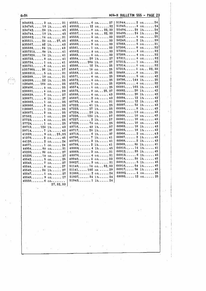
M34682 • . . . . . 3 oz . . • . . . 31 H34740 • . • . . 1 0 lb . • . • • • 45 M34742 . . . • . 2! lb • • • • • . 45 M34744 . . • . . 1 0 lb • . . . • • 45 M35062 . . . . . H o z . . . . . . 31 M35511. • . . . 2! o z . . . 27, 45 M35567 . . • • • Bi lb • . . . . • 43 M35598 . . . . . 8> lb . . . . • • 43 M35731A . . . . 8> lb . . . . . . 41 M35732A . . . . H lb . . . . . . 41 M35733 . . . . . . 8 oz • • • • • • 41 M35734 • • • • • • 1 o z • . . . • • 41 M35751. • . . • . 6 o z . . . . . . 41 N35798N • • • , 36 lb. , . • • . 37 M36331A . . . . . 5 o z . . . . . . 31 M36389.
-. , . . 10 oz • . , . , . 31
M36399 . . . . . 21 lb . . . . . . 35 }136400, • • • 10-k oz • • . • . . 35 M36406, • • • • • !- oz • . . . . . 35 M36601. • • • • , 1!! o z • • . • • • 39 M36639 • • • , , . 7 o z • . • , . • 27 M36671. . . . . . 4 lb . . . . . . 27 M36865 . . . . . . 1 oz • • • • • • 35 M36866 • • , • • • 3 o z . • • • . . 35 !136867 . . . . . . 1 lb . . . . . . 35 M36871 • • • , , , 3 oz • . • • . . 35 37 502 . • . • • • • 1 oz • . . . . . 29 37723 • • • • • . • 4 oz • . . . . . 25 37724 • . . . • . • 1 oz . . . • . • 25 39713 • • . • • 12! lb . . . • . . 43 39714 . . . . . . . 7 lb . . . . . . 43 41039 . . . . . • . 9 o z . . . 2 5 , 3 5 41370 . • . . . . . 2 o z . • • • • • 45 44126 . • • . . . • 2 oz . . . 0 • • 24 44671. . . . . . . 1 oz . . . • • • 24 44954 . . . . . • 86 oz • • • • • • 31 45235 • . . • • • 8! o z • • • • . • 27 45236 . . . • • • H oz . . . . . . 27 45542 . . . • • • . 5 oz • • • • • • 25 45543 • . • • • • . 7 oz • . • . • . 27 45544 • . . • • 0 . 8 oz • . . . . • 27 45545 . . . . . . 3> lb • • . • . . 27 45547. 0 . • • . • � oz • • . • . . 27 45548 . • . • 0 . 0 9 oz • . • . . • 27 45550 . • • • . • • 6 oz. 0 . 0 . . . •
27, 32, 33
M14-H BULLETIN 555 - PAGE 23
45551. 0 0 • • 0 . 6 oz. 0 0 • . . 27 45553 • • 0 . 0 0 12 oz. 0 . 0 . • 32 45556, 0 • • • • 0 ' oz • . 0 32, 33 45557 . • . • . . . t oz • . . 32, 33 45558 . . . . . • . 4 oz . . . . . • 33 45559 • . • . • . • 4 oz . . • . . . 33 45560 . • • • • • . 3 oz . . . • • . 33 45561. . . • • • . 1 oz • . • . . • 33 45562 . . . . • • . ' oz • • . • . • 33 45563 • • . . 0 . 0 t oz. 0 • • ·· • • 33 45564 . • . • • . 20 lb . . . . . . 27 45565 • • . . • 20> lb . . . . . . 27 45566 . . • . • . 11 1� • • . . . 25 45567 • . . • 0 0 U: oz . . . . . . 25 45568 . . . . . . . . oz . . . • • . 25 45571. • . . . • . 4 oz . • • . . . 25 45572. 0 • . • 0 . t oz. 0 • • • 0 25 45573 . • • 0 0 . 0 1 oz . • . . . . 25 4557 4 • • . . • • 0 -4- oz . . . . . . 25 45575 . . . . . . . ' oz . . . 25, 27 45686 • . . • • . . 4 oz • • • • . . 43 45687 . . . 0 • • • 2 o z • • • • ; . 43 46785 • • 0 0 0 • • 8 oz. 0 . • . . 31 47222 . . . . . . 41 lb . . . . . . 25 47223 . • . . . . 37 lb . . • . . • 25 47224 • . . . . . 2 0 lb • . . . . . 25 47226 . . . . . 1 2 ! lb . • . . . . 27 47227 . . • . . • . 2 lb . . . . . . 27 47228 • . . . • . 7! oz . . . . . • 25 48716 . . • . • . H lb . . . . . . 37 48717 • • • • • . 2l lb . . . . . . 37 48718 • . . . • . . 6 lb . . . . . . 37 48796 . . . . . . . 7 lb . • • . • . 41 48797 . . . . . . . 3 lb • • • . . . 41 48798 . . .. . . . 2 lb . . • . . . 41 48868 • . . . • . • 4 lb . . . • . . 45 48869 . . . . • . . 3 oz . . . • . • 31 48870 . . . . . . . 4 o z . . . . . . 31 49940 . . . . . . • t o z • . • • • . 33 50627 • • • . • • . 3 oz • . . . . . 31 51140 • . . . • . H o z • . • 32, 33 51141. . . . • t M oz, • . . . . 29 51860 • • • • • • • 2 o z . • • . . • 24 51937 • • • • • . 31 1� • . . . . 24 51943 . . . . • • 0 1 lb • . • . . . 24
51944. 0 • • • • 2 oz . • . . . • 24 51945. 0 0 • • • ' oz • . . . . . 24 55494 • • • • • 21 lb • • • • . . 24 55495 . . . . • 2 1 lb . . . . . . 24
55627 . . . . . . 1\" oz . . . . . . 25 56246 . . . . . . 2 lb . . . . . . 39 57068 . . . . . . 5 o z . . . . . . 31 57306 • . • . . . 8 oz . . . . . . 32 57308 • . • • . . ' oz . • • . . . 32 57309, . 0 • • • 4 o z . . • • . • 32 57311. • . • • • ! oz . . • 0 • • 32 57312 • • . • • 0 1 oz • . . . . . 32 57314 • . . • • . ! o z • . . . . . 32 57318 • • . . . . ! o z . . . 32, 33 58468 . . . . . . ' oz • • . . . . 25 59046 • . . . • . 5 oz . . . . . . 42 59796 . . . . 1 4 > lb . . . . . . 25 62609 • . . . • . 4 oz • . . . . . 32 66891. . . . 1 6 5 lb . . . . . . 42 66892 . • . . • 20 lb . . . . . . 42 66893. ; . . . 20 lb . . • . . . 42 66894 . . . . . 12 lb . . . . . . 42 66896 • . . . • 12 lb . . . • . . 42 66897 . . • . . 5! lb . . . . . . 43 66898 • • • . . • 8 lb . . . . . . 43 66899 . . . . . 1 0 oz • • • • • • 43 66900, . . . . 10 oz • • . • . 0 43
66901 . . . . • 10 oz • • • • • . 43 66902, . . . . 10 oz • . . . . . 43 66903 • . . . • 18 lb . . . . . . 43 66905 • . . . . 18 lb . . . . . . 43 66906 • . . . . . 2 oz • . . . . . 4.3 66907 . . • • . . 2 lb . . . . . . 43 66908 . . . . . . 2 lb . . . . . . 43 66909 . . . . . 8! lb . . . . . . 41 66910 . . . . . H lb . . . . . . 41 66912 . • . . . 35 lb . . . . . . 45 66913 . . . . • . 6 lb . . . . . . 45 66914 • . . • . 3! lb . . . . . . 45 66915 . . . . . . 5 lb . . . . . . 45
66916 • • . . . 5> lb . . . . . . 45 66917 • . . . • 5> lb . . . . . . 45 68092 • . . • . 0 t oz . • . . . . 25 68093 • . . . • 12 oz . . • . . . 25
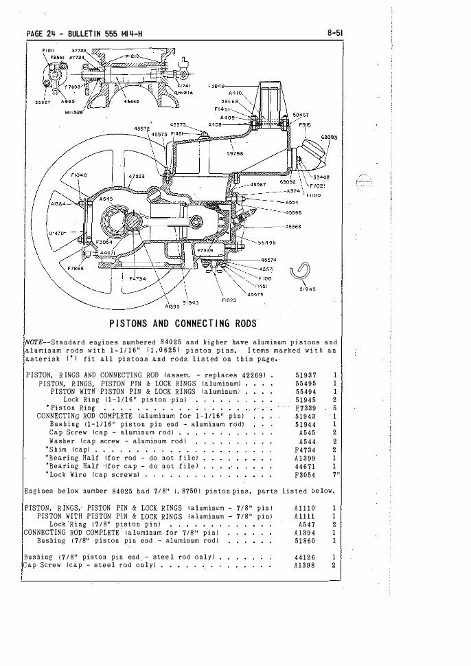
PAGE 2� - BULLETIN 555 MI �-H
FIOI I 3772
���::· � 55527 A695
Mll.l528
P I STONS AND CONNECT I NG RODS
8-51
� 5 1 9 4 5
NOTE--Standard engines -numbered 8 40 2 5 and h i g her have aluminum p i s tons and aluminum r o d s w i t h 1 - 1 / 1 6 '' ( 1 . 0 6 2 5 ) p i s t o n p i ns. I t ems marked wi t h a n a s t e r i s k ( • l f i t all p i s t o n s a n d r o d s l i s t ed o n t h i s p a g e .
P I STON, R INGS AND CONNECTING ROD l a s s em. - replaces 42269 J P I STON, R INGS, PISTON PIN & LOCK RINGS \aluminum)
PI STON WITH PI STON PIN & LOCK R I NGS !aluminum,\ Lock Ring ( 1 - 1 1 1 6 " piston p i n )
"' Piston Ring . . , • . . . . . . . •
CONNECTING ROD COMPLETE (aluminum for 1 - 1 / 1 6 " p i n ) B u s h i n g ( 1 - 1 / 1 6 " piston p i n end - aluminum rod) Cap Screw (cap - alumin urn rod) , ,
Washer \cap screw - aluminum rod ) * S h im (cap) • • , • • , • •
'"Bearing Half (for rod - do not f i l e ) *Bearing Half (for c a p - d o not f i le l * Lock Wire (cap screws) .
5 1 9 3 7 I 5 5 4 9 5 I
55494 I 5 1 9 4 5 2 F7339 5 5 1 9 4 3 I 5 1 94 4 I
A 5 4 5 2
A 5 4 4 2 F4734 2 A 1 3 99 I 4 4 6 7 1 I
F3054 7"
Engi nes be low number 84025 h a d 7/ 811 ( . 8750 1 p i s t o n pins, parts l i s t e d be low.
PISTON, R INGS, PISTON PIN & LOCK R INGS t aluminum - 7 / 8 11 p in l PISTON WITH PISTON PIN & LOCK RINGS t a luminum - 7 / 8 " p i n l
Lock R i n g 1 7 / 8 11 piston p i n ) CONNECTING ROD COMPLETE t a luminum for 7/811 p i n )
Bushing ( 7/811 piston p i n end - aluminum rod )
Bushing ( 7 / 8'' piston pin end - stee l rod o n l y ) C a p Screw ( c a p - s t e e l r o d o n l y ) . .
A I I I O A llll
A 5 4 7 A l 3 9 4 51 860
4 4 1 2 6 A l 3 9 8
I I 2 I I
I 2
6-5� M I4-H BULLETIN 555 - PAGE 25
C Y L I NDER AND C RAN KCASE
CYLINDER AND CRANKCASE WITH STUDS, THROTTLE VALVE AND COVER. 47222 1 Throttle Valve . • • . . . , . . . , 45542 1 Gu ide { throttle valve) . . . • . • 37723 1 Cover ! t h rottle valve - wi t h stopl QH-21A 1 Gasket ! t h rottle gu ide and coverl P-21D 2 Packing ! throttle sterol . . F7608 1 Washer !packing pressure) • . .Hl8528 1 Spring (packing pressure) • . 37724 1 THROTTLE ARM, SCREW AND NUT . A 6 9 5 1
Screw !throttle valve arm) , , F2581 1 N u t ! throttle valve arm screwl Ft o l l 1
CYLINDER AND CRANKCASE WITH STUDS AND COVER 47223 1 Stud (side bearing and carburetor - 1-3/S" J A 1 3 6 4 6 Stud ( s ide bearing - 1 - 1 1 / 16" J • • M17647 4 Stud !cylinder head ) . • . • • . . . . . .A554 8 Stud 5 / 1 6 x 5- 1 /411 {water hopperl 45573 2 Stud 5 /1 6 x 1 - 5 / 1 6" !water hopper) . . , 45575 6 Stud 1 / 4 x 7/811 ! throttle guide & cover) 55627 -4 Cover !water j ac ket bottom) 45571 1 Gasket lcover l , • , , • • • • 45574 1 Stud 5 / 1 6 x 1 - 5 / 1 6" (cover) 45575 4 Hex Nut 5 / 1 6 " (use F1100 L. W. J F1 4 5 1 4
Screw ( throttle guide and cover) F1903 4 Priming Cup • • • . . . . F1741 1 Drain Cock {c rankcase) • • F7868 1 Drain CoCk (water j acket ) . ,. . Fl023 1 Cylinder Head • • • • • • . b.'$) <HR __. 1 Gasket (cyl inder head) • . 45567 1 Nut {cylinder head stud) . A524 8 Washer (cyl inder head s t u d ) 4 5 5 6 8 8 Gasket {carburetor t o crankcase) D-470 1 Nut lcarburetor s t u d ) • . . . • F1040 2
WATER HOPPER - COOL I NG SYSTn1
WATER HOPPER WITH CONDENSER, STUDS AND FILLER CAP Cooling Condenser • . • . . .
WATER HOPPER WITH STUDS lcap included) Stud 5/16 x 1 - 1 14" (water h opper ) Stud 5 / 1 6 x 5-1/4" (water hopper) Stud 5 / 1 6 x 1 - 1 1 / 1 611 ( condenser & filler neck) Gasket ( f i ller neck to hopper ) FILLER NECK lwi th cap) • • •
FI LLER CAP lwith gasket) Gasket ( f i ller capl
Gasket l condens·er to h opper l Clamp Bar (short - for end of condenser) Clamp Bar {long - for side of condenser) Hex N u t 5 / 1 6" ( condenser t o hopper studs) Gasket { h opper t o cylinder)
Hex Nut 5 / 1 6n ( hopper studs)
Overflow Hose (not i l l. J • •
Fiber Clip ( overflow hose - not ill. ) Rust PreVen tat ive • . • . • . • • . .
GA S KE T S ET �7228
47224 1 F3849 1 59796 1 45575 6 45573 2 58468 1 6 68092 1 68093 I F51 1 5 1
A406 1 A408 1 A 4 1 0 2 A409 2
F145l 1 4 45572 1 Fl451 8
F300S 2 1 11 H12024 1
41039 1
All g askets ( including condenser gasket) and the throttle valve stem packing may be obtained under one symbol by spec i f ying 47228 gasket set.
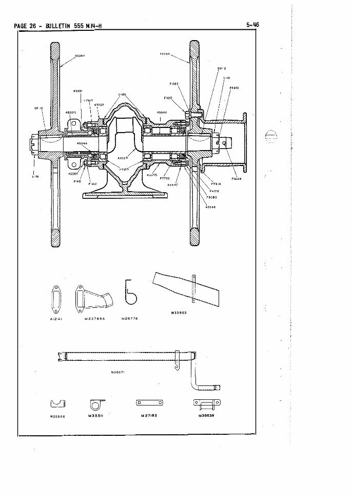
PAGE 26 - BULLETIN 555 M 1�-H 5-�
M33953 A l 2 4 1 M33789A M26776
1Jt ::
�. M36671
Oi } -
C:::::'J g (o o) [ado) M22506 M35511 M 27165 M36639
6-5� M14-H BUllETIN 555 - PAGE 27
FLYWHEELS - CRANKSHAFT S I DE BEAR I NGS
Flywheel !timer or magneto side) Flywheel !belt side} Key ( flywhee l ) . . . Nut ( flywheel) . . .
Cotter 5/32 x 1-1 /2" Pin (starting crank)
CRANKSHAFT WITH BEARINGS, SLEEVE AND OIL SEAL RACE Crankshaft only . . . . • . . Bearing with Races ( inboard) Bearing with Races ( outboard) Spacer (belt side) Oil Seal Race (t imer side )
Gasket (bearing casing l Stud (bearing casing - 1-3 /8" l Stud !bearing casing - 1 - 1 1 /-l Sn J Nut (bearing casing stud)
BEARING CASING WITH STUDS ! timer side) Stud 5 / 16" x 1-5 / 1 6" Hex N u t 5 / 1 6 " (use FllOO L. W. l
Oil Seal ! t imer side) Support Casting ! t imer)
COVER WITH OIL SEAL !bearing casing, belt side) Oil Seal only • .
Gasket (cover l Screw {cover - 1 /4 x 7/8" - use F3083 L W. l Bearing Casing (belt side)
Timer Cam . . Key {timer caml . . . . . . Set Screw {hollow head - early M14-H-1J
S I DE EXHAUST PARTS
Exhaust Elbow {on engine) Cap Screw 3 / 8 x 1 - 1 / 2 " hex head Hex Nut 3 / 8" brass . . . . Exhaust Tubing (specify lengt h ) Exhaust Outlet Ion rail skid ) Gasket {elbow to engine) . . Support Strap (exhaust tube) Cotter 3/16 x 3-1 /2" . . .
START ING C RANK
Starting Crank • . . • . . Starting Crank Holder (plain) Starting Crank Holder fwith loop) BeaTing Catch fan step plate) Spacer (bearing catch - thick - M14-H-2l Spacer (bearing catch - thin - M14-H-2l Wear Plate (on foot board - Ml4-H-l l . .
45564 45565 QB-12
L-IB F2931 F1048
47226 A l 0 2 5 F7013 F7792 45543 45544 U-15E Al364
Ml7647 FIOOO
47227 45575 F1451 F7614 45551
45548 F7614 45547 F4178 45545
45550 F2551 F2447
M33789A F2492 F7702 F7762
M33953 Al241
M26776 F3503
M36671 M22506 M35511 M36639
45235 45236
}1271 8 5
1 1 2 2 2 1
1 1 2 1 1 1 2 4 4 B
I 4 4 1 1
1 1 1 4 1
1 1 1
1 2 2
37!11
I 1 1 I
1 I 1 1 1 6 1

PAGE 28 - BULLETIN 555 M 1'1-H
F1969
F19'il
Ai386
F7901
1 -'18 MI4-H BULLETIN 555 - PAGE 29
C5 CARBURETOR
Gasket (carburet or· to crankcase - inc. in gasket set) "' Ga�ket Set ( c omplet·e for C5 carburetor l .
FAIRMONT C5 CARBURETOR Complete CARBURETOR BODY Complete {wit h needle valve guide, needle
valve seat, and check valve seat) CARBURETOR BODY !with check valve seatl
*Valve Seat ( f or either check or air valve) Guide ( needle valve) • � • • •
Gasket (needle valve g uide) Cap Screw '4 x i 11 ( needle valve guide)
* Seat (needle valve ) • • • • •
Gasket ( needle valve seat) • •
"'Needle Valve (yoke t ype - lengt h 3 - P J • •
Washer tOr gasket - needle valve friction) Lock Spring ( under needle valve)
•check Valve !same as air valve) • • • • • •
Check Valve Stem !wit h lower nut - lengt h 2-5 / 8 " 1 "'Spring !check valve - 1-5 / 16 11 free lengt h )
Cover ( c he c k Valvel • • • • • • •
Gasket (check valve coverJ • • • • •
Cap Nut ( c heck valve stem upper) Gasket (or washer - valve stem nuts I •
FLOAT BOWL Complete ( w i t h f loat and strainer) FLOAT BOWL ( w i t h f loat valve seat)
• seat ( f loat valvel Gasket ( f loat valve seat)
Float with Lever (metal - replaces A1336) • H inge Pin ( f loat lever)
Bearing Screw ( h inge pin) •Float Valve
Strainer BCMl only •
Screen ( s trainer) Gasket ( strainer b owl upper) Cap Nut (strainer b ow l) Gasket (cap nut - strainer bowl lowerl
Gasket ( f loat bowl t o carburetor body) Prain COck complete ( f loat bowl) Gasket (drain- Cock) • • • • • • • •
AIR VALVE CAGE (·with c h oke but· less air valve ) AIR VALVE CAGE (with valve seat) ·•
'"Valve Seat ( f or eithei' check or ah valves ) Choke S_haft • • • • • • • • • • •
Choke Disc • • • • • • • • • • • •
Screw ( c hoke disc - self tapping) CHOKE ARM ( w i t h c lamp screwl • • •
Mac hine Screw { c hoke arm c lamp) Hex Nut l c larnp screwl Lock Washer 3/ 16" • • • • • • •
Spring ( c hoke arm) • • • • • • • •
Air Valve Stem (with lower nut - leng t h 3 1!- " l • Air Valve (same ·as check valve) • • •
•spririg (air valve - 1" free length! •
Hex Nut (air valve stem upper) Gasket {or washer - valve stem nuts)
CARBURETOR SERV ICE K I T 5 1 1 � 1
D-47D I Al389 I A l 3 18 I
Al388 I Al351 I A1353 I Al331 I Al332 I F7370 2 Al327 I
Al326 I
Al357 I EZ453 2
A646 I EZ455 I Al354 I EZ456 I
AI356A I EZ474 I
EZ454 I EU53 2 Al371 I Al387 I Al368 I Al326 I 37502 I AH41 I Al384 2 Al334 I
A1369A I Al367 I Al366 I F7901 I EZ540 I EZ541 I EZ530 I EZ540 I Al362 I A1375 I
Al353 I Al347 I
Al350 I F6470 2 Al386 I Fl971 I Fl969 I Fl692 I Al349 I Al359 I EZ455 I Al361 I
· F7119 I
EZ453 . I
For major carburetor repairs, all -gaskets, valves, seats, springs and hinge pin can be obtained under one symbol by- specifying 51141 CS carburetor service kit. This kit inc ludes items listed above marked w i t h an - asterisk r • J and in the quant ities shown.
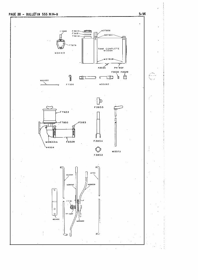
PAGE 30 - BULLETIN 555 M 14-H
, � V
M 7806
, ___ i ! _-M27807-------_
�- "
TANK COMPLETE Ml5066
M 34 4 1 0
[_--M 2 1 a o a--------.
/ 7 F2035 PH-90F
F3030 F3029
� dl l � I ln 6 M34682
F 7 506 M35062
F 3 8 5 5
F 7 9 2 3
F5193
F 3 8 5 4
4 4 9 5 4 0 Ml337 3 F3853
467B5
M2S840 M26839
F7121
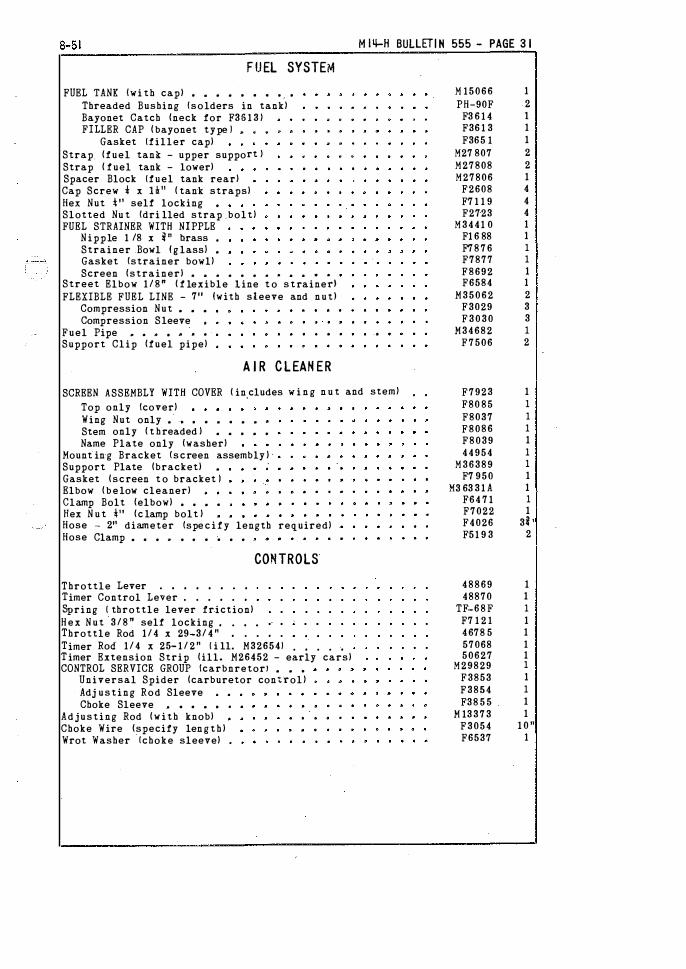
8-51 M 11!-H BULLET! N 555 - PAGE 3 1
FUEL SYSTEM
FUEL TANK fwi th capl • � • • • • • • •
Threaded Bushing {solders in tankl Bayonet Catch (neck for F35 1 3 l FILLER CAP ( bayonet type l .. . .
Gasket (filler cap) Strap_ (fuel tank - upper support J Strap ( fuel tank - lower) Spacer Block (fuel tank rear) Cap Screw 1 x H11 ( tank straps) Hex Nut * 11 self locking •
Slotted Nu t {dri lled strap .bolt) FUEL STRAINER WITH NIPPLE
Nipple 1 /8 x � n brass •
Strainer .Bowl ! g lass} •
Gasket {strainer bowll Screen (strainer) . . . . . . . . . . .. .
Street Elbow 1 / 8 " ( f lexible line t o s t rained FLEXIBLE FUEL LINE - 711 !with sleeve and nutl
Compression Nut • • •
Compression Sleeve Fuel Pipe .. . , • " • •
Support Clip (fuel pipe)
A I R CLEAN ER
SCREEN ASSEMBLY WITH COVER ( in,cludes w i n g n u t and steml
Top only !cover) Wing Nut only • -· • • • • • • •
Stem only ( t hreaded ) • • • • •
Name Plate only (washer) Mount in·g Bracket {screen assembly ) Support Plate (bracket) •
Gasket (screen t o bracket l Elbow ( b e low cleaner) Clamp Bolt (elbow) • • • •
Hex N u t �'' (c lamp bolt ) •
Hose - 211 diameter {spe c i f y length required) Hose Clamp • • • .. • • • • • •
Throttle Lever . • • • • • . •
Timer Control Lever . . . • . •
Spring ( throttle lever friction)
CONTROLS
H e x Nut 3 / 8 " self locking • . • • Throttle Rod 1 / 4 x 29-3/ 4 " • . . • .
Timer Rod 1 / 4 x 25- 1 / 2 " ( i ll. M326541 . • . . • Timer Extension Strip (ill. M26452 - early cars) CONTROL SERVICE GROUP !carbnretorl • • •
Universal Spider (carburetor cont.roll Adj usting Rod Sleeve Choke Sleeve _. • • • , •
Adjusting Rod (with knob) Choke Wire (specify len g t h ) Wrot Washer !choke sleeve) •
M 15066 PH-90F
F3 6 1 4 F36 1 3 F365 1
M27 807 M27808 M27806
F2608 F7 1 1 9 F2723
M3441 0 F1 6 88 F78 7 6 F7877 F8692 F6584
M35062 F3029 F 3 0 3 0
M34682 F7506
F7923 F80 85 F8037 F8086 F8039 44954
M36389 F7 950
M3 63 3 1 A F64 7 1 F7022 F4026 F51 9 3
48869 48870
TF-6 8 F F7 1 2 1 4678 5 57068 50627
M29829 F3853 F3854 F38 5 5
M 13 3 7 3 F3054 F6537
1 2 1 1 1 2 2 1 4 4 4 1 1 I I 1 1 2 3 3 I 2
1 I I I 1 I I 1 1 I 1
3l ' 2
1 1 I 1 1 1 1 I 1 I 1 1
1 0 " 1

PAGE 32 - BULLET I N 555 Mlq-H 8-51
ADJUSTABLE WEATHERSEALD T I MER
NOTE--This t imer is used on RO-C battery ignit ion engines numbered 88480 and h i g her. I t is also applicable t o earlier RO-C units.
WEATHERSEALD TIMER COMPLETE !adjustable! . . . . . . . . . .
MOUNTING CASTING (complete - halves not sold separately ) . Spacer (steel - lower - casting halves ) Spacer (cork - upper - casting halves) Cap Screw - 5 / 1 6 x 7 /811 hex hd. Clamp Screw 5 / 1 6 x 3 /411 fillister hd. Lock Washer 5 / 1 611 (light) . . . . . . Stop Pin 7 /3 2 x 1 / 2 "
-. . . . . . . . .
Pivot Pin 1 / 4 x 1-1/8" !grounds t imer t o body)
TIMER BODY COMPLETE !with blade points and condenser) Body (with gasket) . . BLADE AND SCREW !service set l
Timer Blade ( w i t h point) Adjusting Screw !with point)
Spring ! t imer b lade - spiral) Clamp Block ( t imer blade) Cap Screw 1 / 4 x 1-3 / 8 " hex bd. Connector Hex Nut Y 1 2-24 . . Ignition Condenser
Arc Adjusting Screw Retaining Ring (adjusting screw) Washer 1 / 4 " ( t h i n ) • • •
Gasket ( t imer body to mounting cast ing )
0
45553 I 57306 I 45556 I 45557 I F2831 I F1009 I F2442 2 F8002 I 57308 I
57309 I 62609 I 51 140 1
A595 I PB-17G I PB-17T I
57312 I F2859 I F4761 2 FI O l l I F7512 I
57314 I FJ0535 I F10536 2
57311 I
NOTE--When applying a new gasket t o timer body moisten adhesive s ide of gasket w i t h gasoline, t hen press into p lace.
TIMER CAM !with wiping block RO-CJ Wiping Block
Key ( t imer cam}
45550 57318 F2551
I I I

8-51 M lq-H BULLETIN 555 - PAGE 33
WEATHERSEALD T I MER (NON -ADJUSTABLE )
NOTE--Weatherseald timers complete, and mounting castings as furnished on e n g i n e s below 8 8 4 8 0 are no l o n g e r s u p p l i ed , Order t h e s e p a r t s f rom A d j u s t able Weatherseald timer parts lis ted on page 32. One piece cam is also replaced by cam w i t h renewable wiping block. Other repair parts f o r t imers on engines below 8 8 4 8 0 are available a s listed below.
5 5 5 8
0
45550
NOTE--All weath erseald timers have blade grounded through t h e clamp block and h o l d i n g s crew, and ground wire mus t b e connected to t h i s terminal. Early t imers· h ad t h e i n s u la t ed c o n t a c t s c rew terminal a t t h e t op and ground t ermi�al a t bottom. Later timers have these terminals reversed as illustrated above, and ground wire connects at top.
Spacer Steel ( lower - casting halves) Spacer Cork (upper - casting halves) . Cap Screw 5 / 1 6 11 x 7/8" hex h ead Clamp Screw 5 / 1 6 " x 3/4u filliste.r head Lock Washer 5 / 1 6 " special Spring- Clip Pins Stop Pin .
TIMER BODY COMPLETE twith blade, points and condenser! Body lwi th gasket) . . . . . BLADE AND SCREW (service setl
Timer Blade (with poin t ) . Adjusting Screw (with poin t )
Spring ( timer blade - spiral) Screw ( t imer blade clamp) Clamp Nut ( t imer blade) Ground Clip . . . . . . . Connector . . . . . . • .
Nut ( t imer adj usting screw) Ignition Condenser Complete
Gasket ( t imer body to mounting casting)
TIMER CAM (with wiping block) Wiping Block
Key ( t imer cam)
Set Screw (used with one piece cam only) et s rew l .
45556 I 45557 I F2831 I F1009 I F2442 2 45558 2 f9256 2 F8002 I
45559 I 45560 I 5 1 1 40 I
A 5 9 5 I PB-17G I PB-17T 1
45562 I 45561 I 49940 I F4761 2 FIO l l I F7512 I
45563
45550 I 57318 1 F2551 1
F2447 I F3032 I
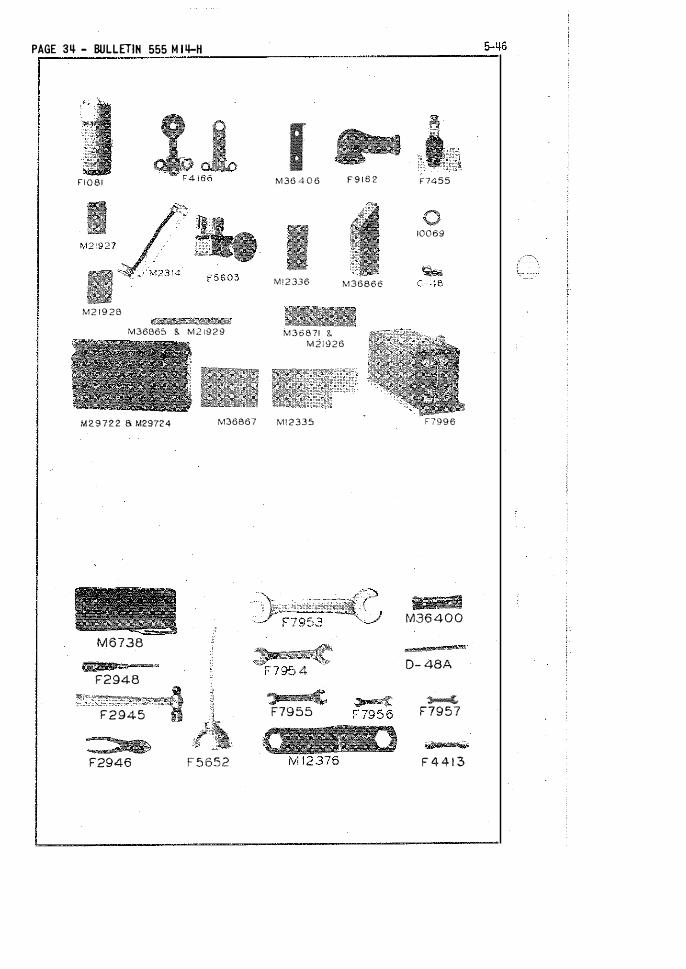
PAGE 3� - BULLETIN 555 M I4-H
I F I 0 8 1 M36 4 0 6 F $ 1 8 2
M ! 2 336 M36866
M2 1 9 2 B
M36B6S & M 2 i929 M36871 8. M21926
M29722 a M29724
M6738
F2948
F2945
S> F2946
M36867 M\2335
F 5 652
:J c. F7955
F7455
10069
F7996
8 I M36 4 0 0
D- 48A
� F7957
F 4 4 1 3
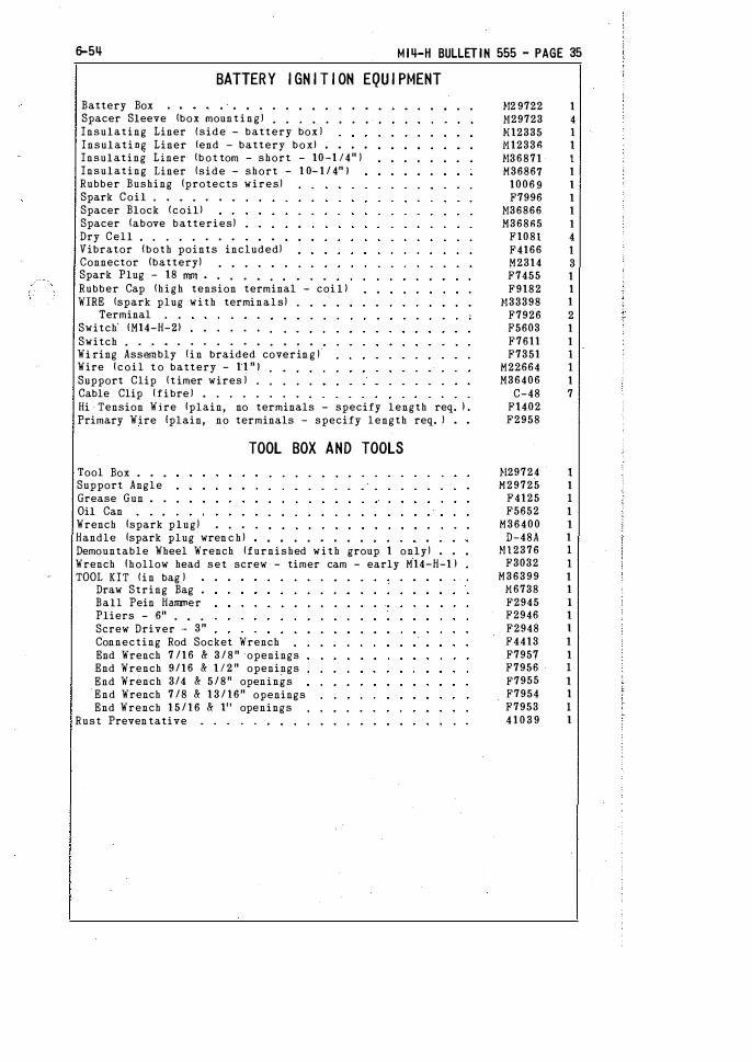
6-5� M I�-H BULLETIN 555 - PAGE 35
BATTERY I GN I T I ON EQU I PMENT
Battery Box • • , . . . . . •
Spacer Sleeve !box moun t i n g ) . . . • . . . •
Insulating Liner {side - battery box ) Insulating Liner lend - battery boxl • • • •
Insulating Liner !bot tom - short - 10-1 14" ) Insulating Liner !side - short - 1 0- 1 / 4" 1 Rubber Bushing !protects wires) Spark Coil , . . . . . .
Spacer Block fcoill Spacer !above batteries) Dry Cell . . . . . . . . .
Vibrator (both points included) Connector (battery) . . . . • .
Spark Plug - 18 nnn • . . . • . •
Rubber Cap !high tension terminal - coi l l WIRE !spark plug with terminals)
Terminal . .
Switch IM14-H-2l . • . . . . . .
Switch . . . • . . . . . . . . . . .
Wi-ring Assembly !in braided coverin g ! Wire {coil t o battery - 1 1 " 1 Support Clip ( t imer wires ) . . . . . Cable Clip {fibre ) . . . . . . . . .
Hi Tension Wire {plain, no terminals - specify length req. J . Primary Wire {plain, no terminals - specify length req. J • •
Tool Box . . . Support Angle Grease Gun • .
Oil Can Wrench {spark plug) . . .
TOOL BOX AND TOOLS
Handle {spark plug wren c h ) • •
Demountable Wheel Wrench {furnished with group 1 only) • •
Wrench {hollow head set screw - timer cam - early M14-H-1 J TOOL KIT fin bag )
Draw String Bag . Ball Pein Hammer Pliers - 6" . • .
Screw Driver - 3" Connecting Rod Socket Wrench . End Wrench 7 /1 6 & 3 / 8 " openings End Wrench 9/16 & 1 1 2 " openings End Wrench 3/4 & 5/8 11 openings End Wrench 7 /8 & 1 3 / 16" openings End Wrench 1 5 / 1 6 & Jl' openings
Rust Preven tative
1!2 9722 1 1!29723 4 .Hl2335 1 M12336 1 1!36871 1 M36867 1
1006 9 1 F7996 1
1!36866 1 M368n5 1
F108! 4 F4166 1 M2314 3 F7455 1 F9182 1
}133398 1 F7926 2 F5603 1 F7611 1 F7351 1
M22664 1 M36406 1
C-48 7 F\402 F2958
1129724 I M29725 1
F4125 I F5652 1
M36400 1 D-48A 1
H\2376 I F3032 1
M36399 1 M6738 1 F2945 I F2946 1 F2948 1 F4413 1 F7957 1 F7956 I F7955 1 F7954 1 F7953 I 4 1 0 3 9 1
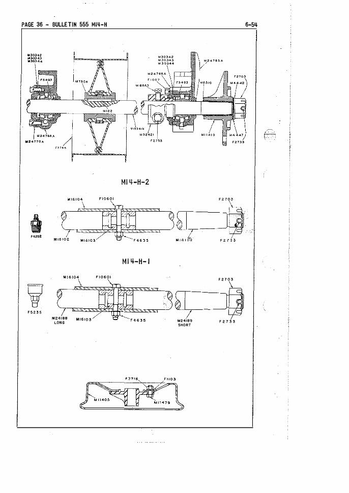
PAGE 36 - BULLETIN 555 MI4-H
lii24770A
F4252
M30342 M30J4J M 3 0344
M247\16A \ F I 007
Ml 't-H-2
Mi lt-H- I
¥ 3 7 ! 8 F I J 0 3
M24189 SHORT
6-5�
M 2 4 7 8 5 A
F2703
F2733
F 2 7 0 3
F 2 7 3 3
.-· -.
6-5� Ml�-H BULLETIN 555 - PAGE 37
1 -7/ 1 6" AXLE S - AXLE BEA R I NGS - THR UST C OLLARS
NOTE--Cars No. 182113, 1 8 2 5 1 0, 187326, 1 94089 and 200937 have 1-5/16" axle, axle bearing and wheel hubs, For these cars ami t parts on this page and see page 54 for 1 - 5 / 1 6 axle, axle bearing and wheel hub parts.
DRIVE AXLE 1 -7 / 1 611 !with nuts and cotters) . . . Axle End Nut (use F2733 cotter) .
DIFFERENTIAL AXLE 1-7 / 1 6 " lwi th nuts and cotters Axle Half CH14-H-2l • • • • • • •
Grease Fitting !H14-H-2l DIFFERENTIAL AXLE 1 - 7 / 1 6 " !with nuts and cotters
Axle Half ( long - M14-H-l l Axle Half (short - M14-H-2l Grease Cup CH14-H-1 l . . . .
Split Bushing (both halves ) Axle Sleeve . . . . . . . .
Center Bolt 5 / 1 6 :x 2-1 / 2" {axle sleeve) Hex Elastic Stop Nut 5 /1 611 Axle End Nut {use F2733 cotter)
CENTER BEARING 1-7 / 1 6" (M14-H-21 Bearing Casing only lM14-H-2l Grease Fitti�g • • • . •
CENTER BEARING 1-7 / 1 6 " (M\4-H-11 Bearing Casing only lM14-H- 1 J Oiler Lt-114-H- 1 ) . . . •
Bearing with Races Cover {bearing casing ) Cover Shim ( . 0 1 0 steel ) Cover Shim ( .007 steel ) Cover Shim I . 005 steel ) Cap Screw 3 / 8 x 1 " hex head
MAIN AXLE BEARING 1 - 7 / 1 6" (M14-H-21 Grease Fitting tM14-H-2l
MAIN AXLE BEARING 1-7 / 1 6 " (M\4-H-11 Oiler (M14-H-1 J • •
Bearing Cas ing only . . Bearing· with Races Cover (bearing casing) Cover Shim ( . 0 1 0 steel l Cover Shim 1 . 007 steel ) Cover Shim ( , 005 steel ) Cap Screw 3 /8 x 1 " hex head
THRUST COLLAR 1-7 /16" (assembled l Clamp Bolt {thrust collar) Hex Half Nut 1 /211 • • • •
Set Screw {drilled head) Lock Wire (per foo t l
- M14-H-2 1 .
- Ml4-H- 1 1 .
WHEE LS - I NSULAT ION ( 1 -7/ 1 6" AXLES )
1 6 " x 1 / 4" DEMOUNTABLE WHEEL !taper bored) Hub only { taper bored) . . , • ,
16" x 1 /4" Demountable Tire only BOLT SET 1 8 each bolts, nuts, and lock washers )
Hub Bolt !alloy s teel) Hex Nut 5 / 8 11 SAE • . . .
Lock Washer 5 /811 • • • •
INSULATION 1-7/16" 1 3-piecel . Insulating Bushing 1-7 ! 1 6n Insulating Washer . Steel Washer • . . . . . •
M15351N 1 F2703 2
M35798N 1 H1 6 1 02 2
F4252 1 H34595N 1
M24188 1 M24189 1
F5235 I
M\6103 1 M 1 6 1 04 I F1 0601 I
F4635 1 F2703 2 487 1 6 I 48717 1 F5158 1
H24763A 1 M24769A 1
F5484 1
F5493 1 H24770A I
H30342 1 H30343 3 !!30344 4
F1007 4 48718 4 F5158 8
H24764A 4 F5484 4
M24765A 4 F5493 4
M24766A 4 !!30342 4 H30343 12 M30344 16
F1007 1 6 M32621 4
F2753 4 F2737 4
M18663 4 F3054 26"
M7677D 4 Mll410 4 Mll405 4 M12177 4 M l l 47 9 3 2
F3718 32 Fll03 32 M8509 4 H8510 4 M4447 4 1!4442 4

PAGE 38 - BULLETIN 555 M 14-H
'rtl..r-YI--�J���=� ' � M22SOO MZB3S6
Fl075 F3598
M l 6725
6-54
Ml635'7
F 1222 �
L'----� __ jdL_ ____________ �PL ____ ��
0 0
M l 5 2 2 7
BRAKE
Brake Lever only 5 / 1 611 (replaces M15227J Bolt 3 / 8 x 1 - 1 / 411 ! brake lever to shaft) Hex Slotted Nut 3 /8" . Brake Shaft . . . . . Bearing !brake shaft l Grease Fitting IM14-H-2J End Arm (brake shaf t ) Set Screw tend arm) Lock Wire !set screw - specify length) Key lend ann) Toggle Link • •
Pin I toggle link - 1 12 x 1-3/411 J •
BRAKE SHOE WITH LINER tassembledl Liner !brake shoe) Hex Nut 5/16" self locking
Pivot Stud (use F3598 n u t ) TOGGLE ARM ! w i t h yokel . •
Body only !toggle ann) Yoke (toggle annl , • .
Lock Nut 1 /211 - 12 thd. TOGGLE ARN I with eye bolt l
Body only (toggle ann - i ll. M33222l Eye Bolt !toggle arm) . Lock Nut 1 / 2 " - 1 2 t hd.
Shoe Hanger fill. Ml6736J Range� Pin ! b rake shoe) Spring lhang�r p i n ) Cotter 3 /1611 x 1n
MIQ-H BULLET I N 555 - PAGE 39
56246 1 M36601 2
F2493 2 M16718 1 M29704 4
F9217 4 M28356 2 M22500 2
F3054 F1222 2
M16725 4 M28761 4 M17193 4 M16397 4
F7120 8 M16730 4 M29229 2 M33222 2
F7106 2 F2702 2
M28762 2 M16727 2 M28351 2
F2702 2 M29705 8 M18930 4 M18931 4
F2866 12

PAGE qo - BULLETI N 555 M l ij-H
FSI58
M2 9630A M304S0 M30451 M30452
MJ ij- H-2
M J ij-H- 1
'
" "",\�T mo� I
MIS226
" '
M 2 <
.
2\�"C moa� Ml5226
'"
.--
6-5� MI4-H BULLETIN 555 - PAGE � I
I DLER - BELT - PU LLEYS
AVTE--Following 1 5 i tems used on M14-H-2 cars:
IDLER PULLEY AND ARM (grease lubricated) Idler Arm . • . . . . . . . . . . .
Cap Screw 3 /8 x 211 hex head • • • .
Grease Fitting . • . . . . . . . .
IDLER PULLEY AND SHAFT ( assembled) Idler Pulley only . . Shaft {idler pulley) . . . Bearing with Races . . . .
Cover !pulley - plai n ) . . Grease Seal Shim (cover - . 0 10 steel) Shim !cover - . 007 steel) Shim (cover - . 00 5 steel) , Cap Screw 5 / 1 6 x 1" hex head Grease Fitting . . ,
NOTE--Following i terns used on Mt4-H-l cars:
IDLER PULLEY AND ARM ! o i l lubricated) Idler Arm . . . . . . . . • . . . .
Cap Screw 3 / 8 x 2n hex head • • • •
Oil Cup (idler arml • • • . • • • •
IDLER PULLEY AND SHAFT !assembled! Idler Pulley only . . . Sh-aft (idler pulley) . . , Bearing with Races . . . . Cover !pulley - plainl . . Shim \cover - . 01 0 steel ) Shim (cover - . 007 steel ) Shim (cover - . 00 5 steel) . Cap Screw 5 / 1 6 x 1 11 h�x head
Spacer Sleeve 4n Ion brake shaf t ) Spacer Sleeve 5 / 8 n Ion brake shaf t ) Pull Rod - 14- 1 / 8 n . . . Strap (lever to spring) Bolt (strap t o lever) Hex Slotted Nut - 3 / 811 ( strap bol t ) Spacer (s trap b ol t ) Hex Nut (guide stud) . Spring - 3-1 / 2n Spring Seat (use w i t h M248 1 4 ) Hex Half Nut - 3 / 8 " (pull rod) Idler Lever . •
Bushing ( lever) Cap Screw { idler lever) Washer leap screw) . . . Cas tle Nut 1 1 2 " SAE
Endless Cord Belt 3-1 /2 x 1 03-1 I 2 11
Axle Pulley ( w i t h bolts - 1011 split steel) Bushing (1-7/16 bore - axle pulley - cut "apart Bushfng f l - 5 / 1 6 bore - axle pulley - cut apart Key (axle pulley bUshing J
Engine Pulley 3-1 / 211 - standard Cap Screw { hex head - engine pulley) Lock Washer 3/8" . . . . . . . . . .
6 6 9 0 9 1 60910 1 F1649 1 F4252 1 4 8 7 9 6 1 48797 1 48798 1 F4216 2
.r115343A 1 F9448 1
H30450 1 M30451 2 M30452 3
F1493 4 F5158 1
M3573H 1 H35732A 1
F1649 1 F4770 1
A 1127A t M15340A 1
A 11 2 8 1 F42t6 2
M29630A 1 M30450 1 M30451 2 M30452 3
F1493 4 H35733 1 M35734 I M35751 I M33435 1 M18043 I
F2877 I M26831 1
F7020 I }12 4814 I
H24813A 2 F1040 2
M 1 5 2 2 5 I 1!1 5226 1
M6540 1 H 2 1 2 8 1 I
F1702 I
F3157 1
F2766 1
before u s i n g ) M7556 1
before using) H24908 I M 1 0 2 I
A 6 92 1 F 1 1 2 5 3 Ft025 3
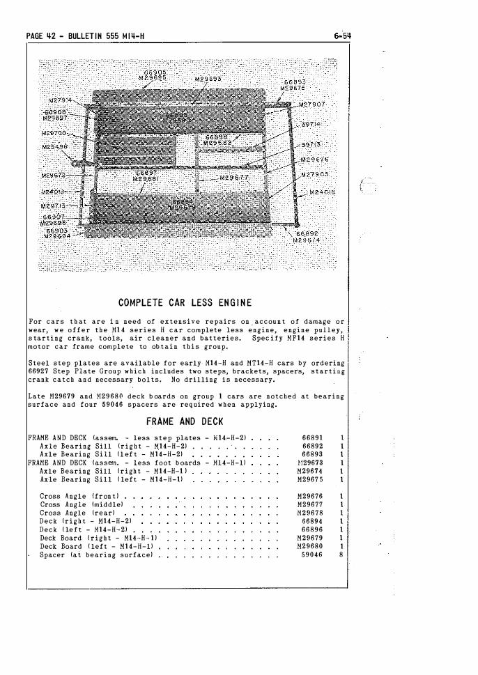
PAGE �2 - BULLETIN 555 M I 4-H
COMPLETE CAR LESS EN G I N E
For cars t h at are i n need of extensive repairs on accou n t of damage o r wear, w e o f f e r the }!1 4 series H c a r complete less engine, engine pulley, s tarting crank, tools, air cleaner and batteries. Spec ify HF14 series H motor car frame complete to ob tain t h i s group.
Steel step plates are available for early- M14-H and MT14-H cars by ordering 66927 Step Plate Group which includes two steps, brackets, spacers, starting crank catch and necessary bolts. No drilling i s necessary.
Late H29679 and }!29680 deck b oards on group 1 cars are notched at bearing surface and four 59046 spacers are required when applying.
FRAME AND DECK
FRAME AND DECK (assem. - less step plates - f.£14-H-2) Axle Bearing Sill ( r i g h t - M14-H-2l . . . . . . •
Axle Bearing Sill ( l ef t - M14-H-2l . . . . . . .
FRAME AND DECK (assem. - less foot b oards - Nl4-H-ll Axle Bearing Sill ( r i gh t - M14-H-1 ) Axle Bearing Sill ( left - M14-H-ll
Cross Angle {fron t ) •
Cross Angle !middle) Cross Angle lrearl Deck (right - M14-H-2) Deck ( left - M14-H-2l . Deck Board ( right - Ml4-H- 1 J Deck Board ( left - H14-H-ll Spacer (at bearing surface) .
66891 I 66892 I 66893 I
1129673 I M2967 4 I M2967 5 I
M29676 I M29677 I M29678 I
56894 I 66896 I
M29679 I 1129680 1
59046 8

M I4-H BULLETIN 555 - PAGE �3
Deck Angle (longitudinal inner - right - Ml4-H-2l Deck Angle (longitudinal inner - left - M14-H-2l Cap Screw 3/8 x 1" hex head !M14-H-2l • . . . . , Deck Angle (longitudinal inner - right - M14-H-ll Deck Angle !longitudinal inner - left - Ml4-H-ll Engine Sill {right ) . , Engiri.e Sill (leftl • . , • . . .
Lift Pipe . . . . . . • • .
Set-Off Channel ( alum. - replaces early channel & block l . Cap Screw 1 1 2 x 211 hex head , Draw Bar • . . • • • . . •
U-Bolt (draw bar) • , • • .
Hex Nut 5 / 1 611 self locking Spacer (step plate - Ml4-H-2l Step Plate !right - M14-H-2l . Step Plate {left - M14-H-2l Bracket {step plate - right front - M14-H-2l Bracket (step plate - left front - .H14-H-2l Bracket (step plate - middle - R. F. & t. R. - M14-H-2l Bracket (step plate - middle - L. F. & R. R. - M14-H-2l Foot Board ! right - M14-H-1l Foot -Board {left - 1114-H-1 J Guard Board 1M14-H-ll Bracket (foot board - right front - M14-H-1 J Bracket (foot b oard - left front - H14-H- l l Bracket {foot board - ' middle - R. F. & L. R. - M14-H- l l Bracket ( foot board - middle - L. F. & R. R. - M14-H-1 J Support Angle (vertical - right rear) Support Angle !vertical - left rear) Hex Nut 5 / 1 6" self locking . . . TOOL TRAY END !right fron t l TOOL TRAY END !left front) . . .
Loop 7 /811 lwindshield strap) Tool Tray End !right rear - M14-H-2J Tool Tray End (left rear - M14-H-2l Tool Tray End (right rear - M14-H- l l Tool Tray End !left rear - M14-H-ll Washer lend plate spacer - H14-H-1 uses 1 2 1 Cap Screw 3 / 8 x 1 " hex head Angle (end plate - right fron t ! Angle lend plate - left front) Angle (end plate - right rear) Angle lend plate - left rear) Rail Skid !right J • • • • •
Rail Skid !left) • • • • . • •
Lunch Bucket Tray (complete) . Spacer ! t h ick - axle center bearing) Spacer ! t h in - axle center bearing)
ENG I NE AND MOUNT I N G
Engine (battery) . . . . Engine Base Strip ( }!14-H-l l Machine Bolt 7 / 1 6 x 4" lN14-H-2J Machine Bolt 7 /1 6 x 3-1 /2" IM14-H-2l Machine Bolt 7 / 1 6 x 3-3/4" lM14-H-1 - replaced Lock Washer 7 / 1 6 " • • • . . . . . .
Spacer Tube {engine bolts - }ll 4-H-l l . , . . ,
by F43141
66897 1 66898 1 F6650 2
M29681 1 M29682 1
397 1 3 1 39714 1
M24018 2 M29685 2
F7387 M25496 1 M22852 1
F7120 6 66906 2 66903 1 66905 1 66899 1 66900 1 66901 1 66902 1
M29694 1 M29695 1 M29693 2 M29689 1 M29690 1 M29691 1 M29692 1 M29687 1 M29688 1
F7120 1 6 M27905 1 H27907 1
F3393 4 66907 1 66908 1
M29696 1 M29697 1 M27675 8
F6650 4 M29698 1 M29699 1 M27913 1 H27914 1 M35598 1 M35567 1 M29700 1
45686 2 45687 1
RO-C-9 1 }128545 2
F4314 2 F3450 2 F4371 4 F1291 4
M16468 4

PAGE �� - BULLETIN 555 M I4-H 6-5�
M 2 7 8 9 8
M I'I-H BULLETIN 555 - PAGE 45
HOUS I N G - L I FT HANDLES
Safety Rail (front J • , • • , • • •
Saddle (front safety rail ) . . . . . . .
Safety Rail (rear) • • . . . . . . . . .
HOUSING !assembled - less seat top - Ml4-H-2l Seat Support (angle iron - front - M14-H-2l Seat Support (angle iron - middle - M14-H-2l Seat Support (angle i ron - rear - M14-H-2J Side Board f lower right - M14-H-2J Side Board flower left - M14-H-2l . • . , .
HOUSING !assembled - less seat top - Ml4-H-l l Seat Support {angle iron - front - M14-H-l l Seat Support !angle i ron - middle - M14-H-U Seat Support {angle i ron - rear - M14-H- l l Side Board (lower right - Ml4-H-ll Side Board flower left - Ml4-H-1J . . . . .
Following i t ems used on all cars:
Side Board {upper righ t ) Side Board {upper l e f t l . Brace { h ousing diagonal) Guide { l i f t handle - end) Guide ( l i f t handle - middle) Catch ( h inged seatl . • . . Windshield Post Holder . . Hex Nut 5 1 1 611 self locking
Control Panel (replaces 4678 6 1 Support Angle (fuel tank � r i g h t ) Support Angle {fuel tank - lef t ) . Sp�cer (seat hinge boltl . . • . .
Starting Crank Holder {with loopl Starting Crank Holder (plain)
SEAT TOP ! h inged - assembled) Side Angle f r i g h t ) Side Angle !left) . • . .
Support Cleat { f ront two) Support Cleat (rear two) Seat Board ( r i g h t ) Seat Board (middle r i g h t - front ) Seat Board (middle right - rear) Seat Board (middle left ) SeGt Board (left ) . . . . .
Hook with Plate , , , . . . Hex Nut 5 / 1 6 " self locking Hex Nut 1 / 4 " self locking .
EXTENSION LIFT HANDLE ! c omplete - right l EXTENSION LIFT HANDLE (complete - lef t l
Reinforcing Strip !with stops) Screw {flat head capl . _ . . • .
Hex Half Nut 3 / 8 " self locking
Instruction Plate Name Plate . . . . Safety First Plate Timer Lever Indicating Plate Belt Identification Plate Blank Number Plate . . . . .
M29719 1 M27810 2 M27769 1
66912 1 66913 I 66914 1 66915 I 66916 I 66917 I
M29709 I
M29710 I M29711 I M29712 1 M29713 1 M29714 1
M29715 1 M32464 1 M2971 8 2 M297!6 4 M29717 2 M26830 4 M28931 2
F7!20 1 8 48868 1
M27894 1 M27895 1 M27899 2 M355!1 1 M22506 1
M27896 1 M27897 1 !!27898 I M27757 2 M27758 2 M27763 1 M�7761 1 M27762 1 M27760, 1 )!277 5 9 1 M27766 1
F7120 8 F7119 22
M34744 1 M34740 1 M34742 2
F7618 2 F7760 2
F301l 1 F7244 1 F3132 1 F7979 I 41370 1 F9231
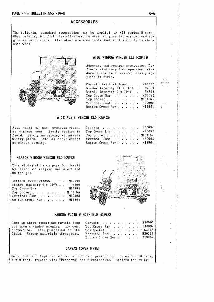
PAGE �6 - BULLETI N 555 Mlij-H
ACCESSOR I ES
The following standard accessories may be applied ·tO M 1 4 series H cars. When ordering for f ield installations, be sure t o g ive factory car and engine serial numbers. Also s h own are some tools that w i l l s implify maintenance work.
W I DE W INDOW W INDSH I ELD M29ijl 9
Adequate bad weather pro tee t ion. Deflects wind away from operator. Windows a l low f u l l v i s i on; easily applied in f ield.
Curtain (with windows ) Window (specify 13 x 1 8 " ) . Window (specify 9 x 19'' ) Top Cross Bar Top Socket . . •
Vertical Post Bottom Cross Bar
M30092 F4899 F4899
M30082 M164!5A
M30093 Ml9964
WIDE PLA IN W I NDSH I ELD M2gij2Q
Full w i d t h of car, protects riders at min imwn cost. Easily applied i n f ield. Strong materials, w i t hstands wintry gales. Same as above except no window open ings.
HARROW W INDOW W I NDSH I ELD M29�21
This windsbield soon pays for itself b y reason of keeping men alert and on the j ob .
Curtain ( w i t h window) Window {spec i f y 9 x 1 9 " ) Top Cross Bar Top Socket • • .
Vertical Post Bottom Cross Bar
M30096 F4899
M16894 MI6415A
M30093 M19964
Curtain Top Cross Bar Top Socket . . Vertical Post Bottom Cross Bar
HARROW PLA I N W I HDSH I ELD MZgqzz
Same as above except the curtain does not have a window opening. Lol-l' cost protec t i on. Easily applied in the f i eld, Strong ma terials throughout.
Curtain Top Cross Bar Top Socket . . Vertical Post Bottom Cross Bar
CANVAS COVER M795!
M30094 M30082
MI6415A M30095 Ml9964
M30097 Ml6894
Ml64 1 5A M30095 M19964
Cars that are kept o u t of doors need this protection. Brown No. 1 0 duck, 7 x 9 feet, treated w i t h " Preserve" for f ireproof ing. Eyelets for tying.
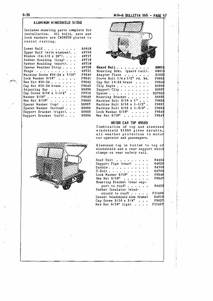
6-511
A LUMI NUM W! HDSHIELD 51 350
Includes mounting parts complete for installation. All bolts, nuts and lock washers are CADMIUM plated t o r e s i s t r u s t i n g .
Lower Half • • • •
Upper Half (with windows ) . Window ( 1 4- 1 / 2 x 28" ) . •
Rubber Noulding !longl •
Rubber Moulding {short l . Canvas Weather Strip Hinge • • . • • • •
Machine Screw 1110-24 x 7 /16" Lock Washer 3 / 1 6 " Hex N u t 1110-24 Cap Nut #10-24 b rass Adjusting Bar Cap Screw 5 / 1 6 x 1-1/4" Washer 5/16" , Hex Nut 5 / 1 611 Spacer Washer ! t op ) Spacer Washer (bottom) Support Bracket (right ) . Support Bracket lleft) .
5 0 9 1 8 4 9 7 0 9 49717 4 9 7 1 8 4971 9 49720 49721 F9540 F9541 F9542 F9543 55995 F9715 F9549 F9550 55997 55998 50933 50934
Guard Rai 1 • • • • • • • • •
}1oun ting Brkt. !guard rail J . Adapter Plate Stove Bolt 1 /4 x 1 / 2 " rd. bd, Cap Nut 1 0-24 brass Clip Angle •
Support Clip • •
Spacer . • • . .
Mounting Bracket Machine Bolt 5 / 1 6 x 1 11 Machine Bolt 5 / 1 6 x 1 - 1 / 211 Machine Bolt 5 / 1 6 x 1 - 3 / 4" Lock Washer 5 / 1 611 Hex Nut 5 / 1611
58812 58613 51932 F9655 F9543 50936 50937
M27928 50935 F9656 F9657 F9658 F9546 F9547
MOlOR CAR TOP 611589 C omb i n a t i on of t op a n d a l u m i n u m w in d s h i e ld 5 1 3 5 0 g iv e s d u r ab l e , a l l wea t h e r p r o t e c t i on t o m o t o r c a r operator and passengers.
A luminum t op is b ol t ed t o t o p o f windshield and a rear support w h i c h clamps o n rear safety rail.
Roof Unit Suppori Pipe (rear) Saddle • • •
U-Bolt • • .
Lock Washer 5 / 1 611 Hex Nut 5 / 1611 Moun t ing Bracket (rear sup
port to roof) Rubber Insulator {wind-
s h i eld to roof) • • •
Gusset lwindshield side frame I Cap Screw 5 / 1 6 x 3 /4" Hex Nut 5 / 1611 light
64424 64620 64709 64708 F9546 F9547
64423
F11486 6 4 6 1 6 F9827
F11487
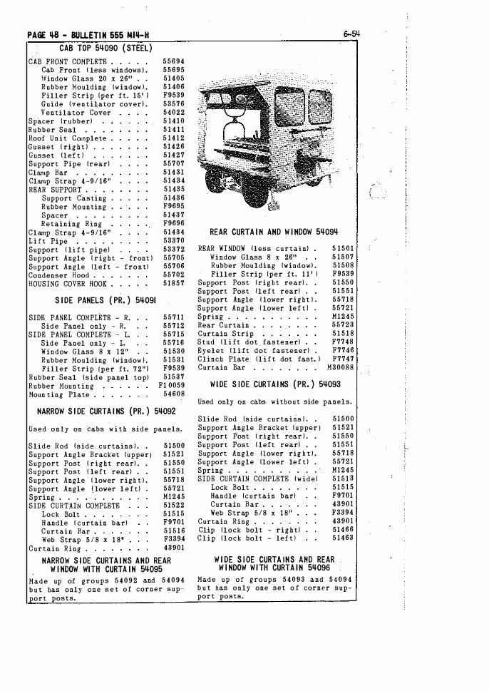
PAGE �8 - BULLETIN 555 MIII-H CAB TOP 5�090 ( STEEl)
CAB FRONT COMPLETE Cab Front ( less win.dows l . W-indow Glass 20 x 2611 • •
Rubber Moulding (window ) . Filler Strip (per ft. 1 5 1 ) Guide (ventilator cover) . Ventilator Cover
Spacer (rubber) Rubber Seal . • . Roof Unit Complete . Gusset ( right ) . _ . . Gusset llef t l Support Pipe (rear) Clamp Bar . . . • .
Clamp Strap 4-9 / 16u REAR SUPPORT . . .
Support Casting Rubber Mounting Spacer . . . . Retaining Ring
Clamp Strap 4 - 9 / 1 6 " L i f t Pipe . . . . . Support ( li f t pipe) Support Angle ( right - front ) Support Angle (left - front) Condenser Hood . . . . . HOUSING COVER HOOK . . .
S IDE PANELS ( PR. ) 5�091
SIDE PANEL COHPLETE - R. Side Panel only - R.
SIDE PANEL COHPLETE - L. Side Panel only - L. Window Glass 8 x 1 2 " Rubber Moulding !window ) , Filler Strip (per ft. 7 2 " )
Rubber Seal (side panel topl Rubber Haunting Moun ting Plate . . . .
55694 55695 51405 5 1 406 F9539 53576 54022 5 14 1 0 5 1 4 1 1 5 14 1 2 5 1 4 2 6 5 1 4 2 7 55707 5 1 4 3 1 5 1 4 3 4 5 1 435 51436 F9695 5 1 4 3 7 F9696 51434 53370 53372 55705 55706 55702 5 1 8 5 7
5 5 7 1 1 5 5 7 1 2 5 5 7 1 5 5 5 7 1 6 5 1 530 5 15 3 1 F9539 51537
Fl0059 54608
NARROW S I DE CURTA I NS (PR. ) 5�092
Used only on Cabs w i t h side panels.
Slide Rod {side. curtains ) . . Support Angle Bracket (upper ) Support Post ( right rear) . . Support Post ( left rear} . . Support Angle ( lower righ t } . Support Angle ! lower l e f t ) Spring . . . . . . . . . SIDE CURTAIN COMPLETE
Lock Bolt . . .
H andle ( curtain bar) Curtain Bar . Web Strap 5 / 8 x 1 811 •
Curtain Ring , . .
5 1 500 5 1 5 2 1 5 1 550 5 1 5 5 1 557 1 8 55721 M1245 51522 5 1 5 1 5 F9701 5 1 5 1 6 F3394 43901
NARROW S I DE CURTA I NS AND REAR W I NDOW WITH CURTA IN 5�095
Made up of groups 5 4 0 9 2 and 5 4 0 9 4 b u t has only one s e t of corner support posts.
REAR CURTA I N AND W I NDOW 5�09�
REAR WINDOW !less curtain) . Window Glass 8 x 2611 Rubber Moulding (window) . Filler Strip (per it. 1 1 1 l
Support Post (right rear) . . Support Post !left rear) , . Support Angle ( lower right ! . Support Angle ( lower lef t ! Spring . . . .
Rear Curtain . Curtain Strip Stud ( l i ft dot fastener) Eyelet ( l i ft dot fastener) , Clinch Plate ( l i f t dot fast. ) Curtain Bar , . . . . , . .
5 15 0 1 5 1507 51508 F9539 5 1 550 5 1 5 5 1 5 5 7 1 8 5 5 7 2 1 M 1 2 4 5 5 5 7 2 3 5 1 5 1 8 F7748 F7746 F7747
M30088
WIDE S lOE CURTA I NS ( PR. ) 5�093
Used only on cabs without side panels.
Slide Rod (side curtaifis l • .
Support Angle Bracket (upper ) Support Post ( right rear ) , . Support Post ( left rear) . , Support Angle (-lower rig h t ) . Support Angle (lower lef t ) . Spring . . . . . . . . . . ·
SIDE CURTAIN COMPLETE !wide) Lock Bolt . . . Handle (curtain bar) Curtain Bar . Web Strap 5 / 8 x 1 8 " .
Curtain Ring . . .
Clip (lock bolt - right) Clip (lock bolt - lef t )
5 1 5 0 0 5 15 2 1 5 1 550 5 1 5 5 1 5 5 7 1 8 55721 M1245 5 1 5 1 3 5 1 5 1 5 F9701 43901 F3394 43901 51466 5 1463
W I DE S l OE CURTA INS AMD REAR W I NDOW W ITH CURTA IN 5�096
Made up of groups 5 4 0 9 8 and 5 4 0 9 4 b u t has only one set o f corner support posts.
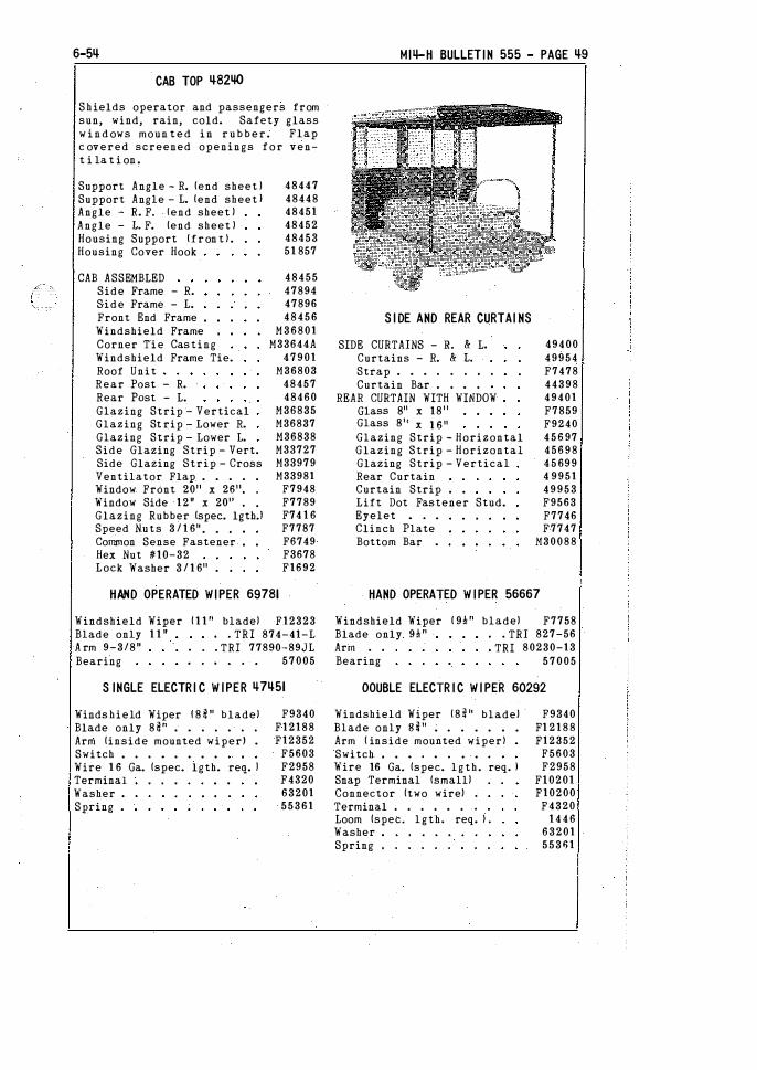
6-5�
CAB TOP �82�
S hields operator and passengers from sun, wind, rain, cold. Safety glass w i n d ows moun t e d i n r u b b e r . Flap c overed screened openings for vent i la t i on .
Support Angle - R. (end sheet l Support Angle - L. (end sheet I Angle - R. F. lend sheet ) Angle - 1. F. (end sheet ) Housing Support (fron t ) . Housing Cover Hook
CAB ASSEMBLED Side Frame - R. Side Frame - L. Front End Frame Windshield Frame Corner Tie Casting Windshield Frame Tie. Roof Unit Rear Past - R. Rear Past - L. Glazing Strip - Vertical Glazing St rip - Lower R. Glazing Strip - Lower L. Side Glazing Strip - Vert. Side Glazing Strip - Cross Ventilator Flap . . . . . Window FrOnt 2011 x 2611, •
Window Side 12 11 x 2011 , •
Glazing Rubber (spec. lgtb.l Speed Nuts 3 / 1 611 • • •
Common Sense Fastener Hex Nut #10-32 Lock Washer 3 / 1 611 • •
48447 48448 48451 48452 48453 51 857
48455 47894 47896 48456
M36801 M33644A
47901 M36803
48457 48460
M36835 M36837 M36838 M33727 M33979 M33981
F7948 F7789 F74 1 6 F7787 F6749 F3678 F1692
HAND OPERATED WIPER 69781
Windshield Wiper Blade only 1 1 11 A rm 9-3/8" Bearing
( 1 1 " blade) F12323 o o TRI 874-41-L
o o o TRI 77890-89JL 0 0 0 0 0 0 57005
S INGLE ELECTR I C W IPER �7�51
Winds hield Wiper ! 8 4 " blade) Blade only 84" . • . . . . .
Arm (inside mounted wiper) . Switch . . . • . . . . Wire 1 6 Ga. (spec. lgth. req. l Terminal Washer •
Spring •
F9340 F12188 F12352
F5603 F2958 F4320 63201 55361
MI4-H BULLETIN 555 - PAGE �9
S I DE AND REAR CURTAI NS
SIDE CURTAINS - Ro & Lo Curtains - R. & L Strap . • • . . . • .
Curtain Bar . . • . . REAR CURTAIN WITH WINDOW
Glass 811 x 181 1 Glass 81 1 x 1 611 Glazing Strip - Horizontal Glazing Strip - Horizontal Glazing Strip - Vertical Rear Curtain Curtain Strip . . Lift Dot Fastener Stud. Eyelet • . . Clinch Plate Bottom Bar •
49400 49954 F7478 44398 49401 F7859 F9240 4 5 6 97 45698 4 5 699 4 9951 49953 F9563 F7746 F7747
}!30088
HAND OPERATED W IPER 56667
Windshield Wiper Blade only 9�" Arm . •
( 9�" blade) F7758
Bearing
o o TRI 827-56 o TRI 80230-13
57005
OOUBLE ELECTR I C W I PER 60292
Windshield Wiper ( 8 � 11 blade) Blade only Si" . . . . . . . Arm ( inside mounted wiper) •
Switch • . • . • . . . Wire 16 Ga. (spec. lgth. req. J Snap Terminal (small) Connector (two wire) . Terminal . . . . • . .
Loom (spec. lgth. req. l . Washer Spring • . . . . . • . .
F9340 F1 2188 F\2352
F5603 F2958
Fl0201 F10200
F4320 1 4 4 6
63201 55361
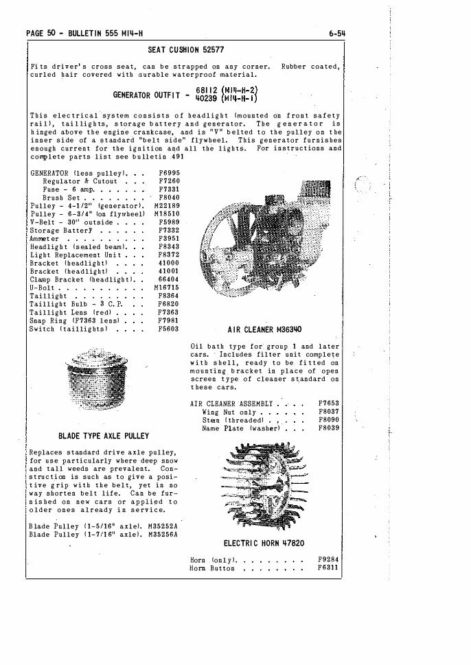
PAGE 50 - BULLET IN 555 M I�-H 6-5�
SEAT CUSHION 52577
Fi ts driver' s cross seat, can b e strapped on any corner. Rubber coated, curled hair covered with durable waterproof -ma terial.
681 1 2 (MI I!-H-2) GENERATOR OUTF I T - �0239 (MI�-H- 1 )
T h i s elec t r i c a l sys tem c o n s i s t s o f headl i g h t (mounted on f ro n t s a f e t y rai l ) , tai l li g h ts , s torage b at te r y a n d generator. T h e g e n e-r a t o r i s h inged above t h e engine crankcase, and i s n y n b elted t o the pulley o n t he inner s i de of a s t andard " b e l t side" flywheel. This generator furnis hes enough current for the i g n i t i on and all the lights. For instruct ions and complete parts list see b u lletin 4 9 1
GENERATOR !less pulley ) , Regulator & Cutout Fuse - 6 iWP· Brush Set . • • . • •
Pulley - 4-1 /211 !generator ) . Pulley - 6-3/4" (on flywheel) V-Belt - 3011 outside Storage BatterY • • . •
Ammet"er • . . . . • . .
Headlig h t ( s e_aled beam ) . Light Replacement Uni t Bracket ( headli g h t ) Bracket {headlight) Clamp Bracket (headligh t ) . U-Bolt • . . .
Taillight . . . . •
Taillight Bulb - 3 C. P. Taillight Lens (red) . Snap Ring fF7363 lens) Switch ( tailli g hts )
BLADE TYPE AXLE PULLEY
F6995 F7260 F7331 F8040
M22189 Ml8510
F5989 F7332 F3951 F8343 F83_72 41000 4 1 0 01 66404
Ml6715 F8364 F6820 F7363 F7981 F5603
Replaces standard drive axle pulley, for use particularly where deep snow and tall weeds are prevalent. Cons t ru c t i on is such as to give a posit ive g rip w i t h t h e belt, yet in no way shorten belt life. Can be furn is hed on new cars or applied t o o lder ones a l r eady i n s e rv i c e.
B lade Pulley { 1-5/1611 axle). M35252A Blade Pulley ! 1-7/1 611 axle ) . M35256A
A I R CLEANER M363�
Oil bath type for_ group 1 and later cars. Includes filter unit complete w i t h s he l l , ready t o be_ f i t t ed on mounting _ b racket in place of open screen t ype o f cleaner s t andard on t hese cars.
AIR CLEANER ASSEMBLY Wing Nut only • •
Stem ( threaded) •
Name Plate (washer)
ELECTRI C HORN �7820
Horn (onl y ) . Horn Button
F7653 F8037 F8090 F8039
F9284 F6311

6-5� M I4-H BULLET I N 555 - PAGE 51
AUTOMOTIVE MUFFLER M21723
This muffler makes the engine except i onally quiet, very l i t tl e red u c t ion i n horse power, Can b e applied at factory or in t h e field.
Tubing (spec i f y length) • . • Clamp ! tubing) • . • , • • ,
F7762 48444
RAIL SWEEPS 50588 BLADE 1YPE
Heavy duty t ype, h inged. All parts are s tee-l except blade proper. Adj ustable for rail clearance. Gives full protect i on due to blade w i d t h . Long lived. Blade easily renewed.
Body - right . Body - left •
Blade only . •
Clamping Plate Hinge Bolt •
Spring . . . . Spring Seat Slotted .Nut Retainer Strap Spacer • . . .
42608 4 2 6 1 1
M23956 M23957
4 2 6 0 6 QB-61C
M30435A F2545 50614
M17032
Muffler only Tail Pipe Bushing • •
Support Angle U-Bolt • .
Angle Clip . •
F6625 M33457 M32070 M32625 M32626 M32627 .
RA IL SWEEPS 50633 HOSE TYPE
Late air hose type. Hinged t o clear rail when car is s e t on or off t h e t-rack. A good serviceable sweep for a l l cond i t i on s .
Clamp Strap . . . Filler Block (for hose) Hinge Bolt 1 /2 x 3-1 / 2 " . Spring • • • •
Spring Seat Slotted Nut Retainer Strap Spacer • .
Hinge Bolt 1 /2 x 2-1 /4".
M34826 M36587
42606 QB-61C
M30435A F2545 50614
M17032 M18562

PAGE 52 - BULLET IN 555 MI �-H
HAND GONG - 1 0 INCH M2gij2�
L o u d , d u r a b l e w a r n i n g Mounted away f r om tools. by pull wire.
Gong only - 10" Pull Wire
s i g n a l . Operated
1337 M16878
HAND GONG - 6 INCH M29�23
Meets m i n imum r e q u i rements. S a f e mou n t i n g .
Gong on ly - 6 " P u l l W i r e
SPR I NG COUPLER M27 1 69
F3444 M17341
B o l t s to d r aw b a r on m o t o r c a r . S p r i n g s c u s h i o n b umps a n d j e r k s w h e n t o w i n g t r a i lers.
JAW COUPLER 48330
Drawbar Coupler Spacer (drawbar) U-Bolt • . . . . Plate {drawbar) Spacer (drawbar)
SAFETY COUPLER I� 1 1 668
I 0-48
4 8 4 04 4 3867
M28684 4 8 4 05 484 06
Provides maximum s a f e t y and . e f f i c iency i n linking trai ler t o motor c ar . h o o k o f 7 / 8 '' r o d w i t h s e l f c losing malleable iron catch.
8ATTERYLESS GENERATOR OUTF IT 5201 1
This electrical system consists of seald beam head light ( swivel mounted on front safety rail ) , t a i l lights and generator. Generator -ts h i n g ed above t he engine crankcase, and is "V" belted to t.he pulley on the inner side of a standard "belt s ide" f lywheel. This generator furnishes current f or a l l l i g h t s and the i g n i t i o n after starting engine on d r y c e l l batteries. For instruct ions and complete parts list see batteryless generator b ullet i n .
GENERATOR { less pulley). Regulator & Cutout Brush Set . • . . . .
F9380 . VAK 4002 • GBM .1012
Pulley - 2-7 /8" {generator) Pulley - 6-3 / 4 " {on flywheel) V-Belt - 3 1 " outside Headlight {sealed beam ) . Light Replacement Unit Bracket {casting ) Washer { f r iction) Taillight Bulb - 3 C. P. Taillight Lens (red) . Snap R i ng lF7363 lens) Switch ( Reversi n g ) Switch ( Ignit ion )
4 8 5 5 5 M 1 8 5 1 0
F7884 F8343 F8372 39178 F8363 F6820 F7363 F7981 F9398 F9399
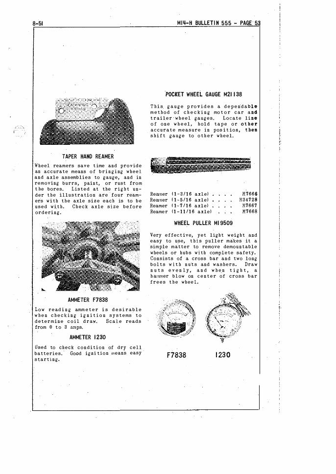
8-51
TAPER HAND REAMER Wheel reamers save t ime and provide an accurate means of b r i n g i ng wheel and axle assemblies to gauge, and in removing burrs, paint, or rust from t he bores. Listed at the r i g h t under the illustration are four reamers with the axle size each is to be used with. Check axle size before ordering.
AMMETER F7838
Low read i n g amm e t e r i s d e s i r a b l e w h e n c h e c k i n g i g n i t i o n s y s t ems t o determine c o i l draw. Scale reads from 0 t o 3 amps.
AMMETER 1 230
Used to check condition of dry cell batteries. Good igni tion means easy starting.
MI�-H BULLETI N 555 - PAGE 53
-POCKET WHEEL GAUGE M21 1 38
T h i s g a u g e p ro v i d e s a d e p e ndable method of c h e c k i n g mo t o r car and t railer wheel gauges. Locate line o f one w h e elr hold tape o r other accurate measure in pos i t ion, then s h i f t gauge to o t h e r wheel.
Reamer ( 1- 3 / 1 6 axle) Reamer { 1- 5 / 1 6 axle) Reamer ( 1- 7 / 1 6 axle) Reamer ( 1 - 1 1 / 1 6 axle)
WHEEL PULLER Ml 9509
M7666 N34728
N7667 M7668
Very effect ive, yet light weight and easy to use, t h i s puller makes it a simple matter to remove demountable wheels or hubs with complete safety. Consists of a cross bar and two long bolts w i t h n u t s and washers. Draw n u t s e v e n l y , a n d w h e n t i g h t , a h ammer blow on center of cross bar frees t h e wheel.
F7838 1 230
PAGE 5� - BULLETIN 555 M I4-H 6-5�
M ill-- H - I
NOTE--Cars No. 1821 13, 1 8 2 5 1 0, 187326, 194089 and 200937 have 1 - 5 / 1 611 axle, axle bearing and wheel hubs, parts are listed below. Check axle size before orde r i n g t hese parts. See page 37 f o r 1 - 7 / 1 6 " axle, a x l e b ea r i ng and w h eel h u b p a r t s .
DRIVE AXLE 1 - 5 / 1 611 !with end n u t s ) Axle End N u t (use F1094 cotter)
DIFFERENTIAL AXLE 1-5/ 1611 !offset) Axle Half !long l . . . . . . Axle Half (short l . . . . • .
Split Bushings (both halves ) Axle Sleeve . . . • . . . • •
Center Bolt 5 / 1 6 x 2 - 1 1 4 " (axle sleeve) Hex Elastic Stop Nut 5 / 1 6 " Grease Cup • • • • • • • • • •
Axle End Nut (use Fl094 cotter ) CENTER BEARING 1 - 5 / 1 611 (assembled)
Bearing Cas ing only . •
Bearing with Races Casing Cover • • • . ,
Cover· Shim 1 . 00 5 steel) Cover S h im ( . 007 steel) Cover Shim ( . 020 steel) Cap Screw 3/8 x 1 hex head Oiler . . • • . . . • .
MAIN AXLE BEARING 1 - 5 / 1 6 " (assembled) Bearing Cas ing only . . Bearing with Races Casing Cover . . . . .
Cover Shim ( . 005 steel ) Cover S h im ( . 007 steel) Cover Shim ( . 020 steel) . Cap Screw 3 !8 x 1 hex head Oiler . . . • . . . . . • •
THRUST COLLAR 1 - 5 1 1 6 11 (complete) Clamp Bolt ! thrust collar) Half Nut 1 /2'' hex . . . . Set Screw (use F3054 lock wire)
Thrust Sleeve 1 - 5 / 1 6"
WHEELS - I NSULAT I ON ( 1 -5/ 1 6" AXLES )
16" x 1 /4" DEMOUNTABLE- WHEEL (taper bored for 1 - 5 / 1 6" ins. l . Hub only ! taper bored) . . . . . . . . . • • •
16" x 1 / 4" Demountable Tire only . . • . . . •
BOLT SET (8 each bolts, nuts, and lock washers) Hub Bolt (alloy steel) Hex Nut 5 / 8 SAE Lock Washer 5 / 8
INSULATION 1-5/16" ( 3 piece) Insulating Bushing 1 - 5 / 1 611 Insulating Washer Steel Washer . . . . . • •
N27685N 1 F2707 2
M34036N 1 M34037 1 M34038 1 M2491 9 1 M24920 1
F1288 1 F4635 1 F5235 1 F2707 2
M24909A 1 N24771A 1
F6553 1 M24772A 1
F5811 3 F5810 2 F5812 1 F1 007 4 F5484 1
M24912A 4 M24767A 4
F6553 4 M24768A 4
F581l 12 F58 1 0 8 F5812 4 F1007 1 6 F5484 4
M27690 4 F2753 4 F2737 4
N18663 4 H2'!692 4
M24914D 4 M249 1 5 4 Mll405 4 N12177 4 Mll47 9 32
F3718 32 F1103 32
M30045 4 N24913 4
N6001 4 F1 6 1 5 4
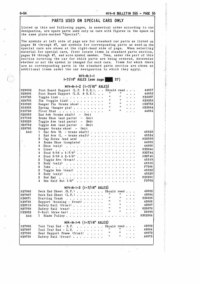
6-5� M I 4-H BULLETIN 555 - PAGE 55
PARTS USED ON S PEC I A L CARS ONLY
L i s t ed on t h i s and following pages, in numerical order according t o car designation, are spare parts used only on cars with figures in the space on the n ame plate marked " Special".
The symbols a t left side of page are for standard car parts as listed on pages 24 t hr o u g h 47, and symbols f o r corresponding parts as used on the special cars are s h own a t t h e r i g h t - hand s i de of p age. When selec t in g material for special cars, f i rs t locate i t ems in standard parts section, pages 2 4 through 47, and note symbol number. Then, under the part o f this s e c t ion cove r i n g the c a r for w h i c h parts are being ordered, determine whether or not the symbol is changed for such cars. I t ems for which there are no corresponding parts i n the s tandard parts s e c t i on are s hown as addi t i on a l i t ems u n de r t h e car d e s i g n a t ion to w h i c h t he y apply.
M29692 M29691 H16725 M28761 M 1 8 9 3 0 M18931 H16730 }!28 3 5 6 H 1 7 1 9 3 M29229 !!2 8762 M29705
Add:
H27905 N27907 }136671 N29710 H29'll 9 M27769 }122852
Add:
M27905 M27907 H27910 H29719
M I II-H- I- I 1-7/ 1 6" AXLES (see page . 37)
M I'I-H- 1-2 ( 1 -7/ 16" AXLES) Foot Board Support (L. F. & R. R. ) . Should Foot Board Support fL. R. & R. F. l . Toggle Link . Pin (toggle link) Hanger Pin {brake shoel Spring ( hanger p i n ) Pivot Stud End Ann !b rake shaf t l cmi t Brake Shoe (and parts) Toggle A rm (and parts ) Toggle Ann land parts) Hanger (brake shoe)
(}ni t Omit Omit
fui t 1 EnJ Arm fR. - brake shaf t ) 1 End Ann IL. - brake shaft} 2 Cap Scre� fend arm) 4 Brake Shoe (complete) 4 Shoe fonlyl 4 Liner 4 Stud 5 / 1 6 x 1 - 7 / 8 " 4 Stud 5 / 1 6 x 2 - 1 / 8 " 2 Toggle Ann (fron t ) 2 Body (only) 2 Yoke . 2 Toggle Arm frearl 2 Body fonlyl 2 Rod End 4 Hex Half Nut 1 / 2 "
MI 'I-H- !-3 ( 1 -7/ 1 6" AXLES) Deck End Sheet fR. F. l Should Deck End Sheet ( L. F. J Starting Crank Support !housing - frontl Safety Rail ( fr on t ) Safety Rail (rear) U-Bolt (draw bar ) 1 Blade Pulley .
MI�-H- 1-� ( 1-7/ 1 6" AXLES) Tool Tray End - R. F. Should Tool Tray End - L. F. Seat Support Frame (fron t ) Safety Rail ( front}
read
read "
read
44057 4 4 0 5 8
H28357 M28358 }132753 }133094
44054
4 5 5 2 3 4 5 5 2 4
}122500 4 4 0 5 5 44056
H32844 M32744 }1327 45
4 5 5 1 9 4 5 5 1 6 F7106 45522 45520
M28351 F2702
43082 43084
M36856 43086 43087
M35078 3 8 0 9 5
M35256A
43082 43084 48072 48073
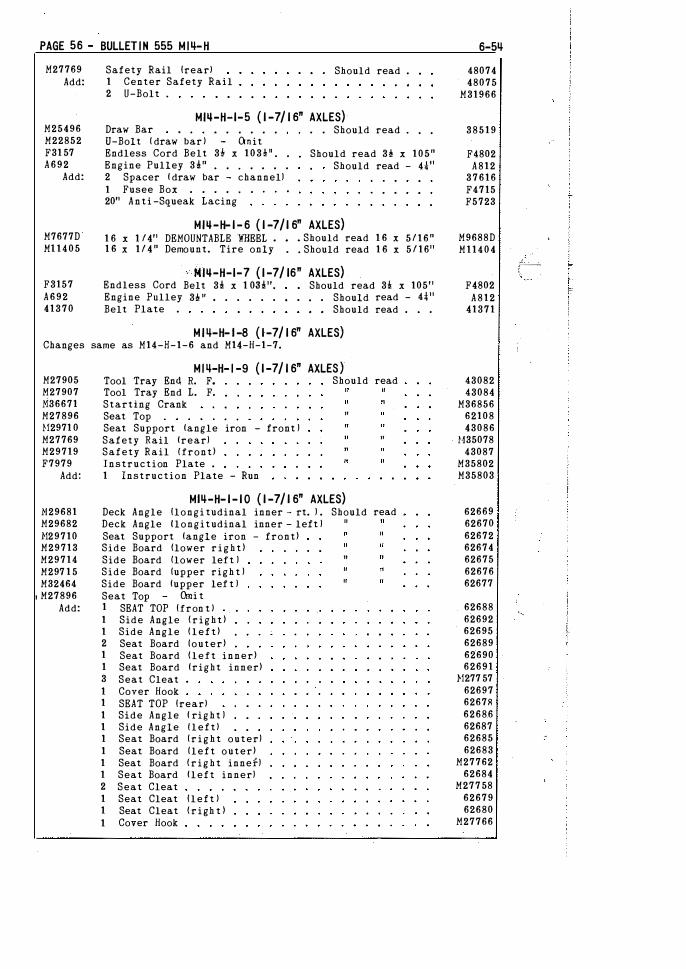
PAGE 56 - BULLET IN 555 M I�-H
M27769 Add:
M25496 M22852 F31 57 A692
Add:
M7677D Ml 1405
F3157 A692 41370
Safety Rail lrearl 1 Center Safety Rail 2 U-Bolt .
Should read .
MJQ-H-1-5 { 1 -7/ 1 6" AXLES) Draw Bar • . . . . . . . Should read . • •
U-Bolt ( draw bar l - Omit Endless Cord Belt 3! x 103! 11 • •
Engine Pulley 3!" • . . . . . . 2 Spacer ( draw bar - channel) 1 Fusee Box . . . . . . . . . 2011 Anti -Squeak Lacing
Should read 3i x 105" Should read - H11
MJQ-H- 1-6 { 1 -7/ 1 6" AXLES) 1 6 x 1 /411 DEMOUNTABLE WHEEL • • • Should read 1 6 x 5 / 1 6 " 1 6 x 1 / 4 " Demount. Tire only . • Should read 1 6 x 5 / 1611
Endless Cord Engine Pulley Belt Plate .
· MJQ-H-1-7 { 1 -7/ 16" AXLES) Belt 3! x 1 0il!11, Should read 3!: x 10511
3P , . . . . . • • , • Should read - H11 • • Should read . . .
MJ4-H- l -8 { 1 -7/ 1 6" AXLES) Changes same as M14-H-1-6 and M14-H-1-7.
M27905 M27907 }!36671 M27896 1!2971 0 M27769 M29719 F7979
Add:
N29681 M29682 }!29710 M29713 M29714 M297 1 5 M32464
I M27896 Add:
MI4-H- I -9 { 1 -7/ 1 6" AXLES) Tool Tray End R. F. Should read Tool Tray End L. F. Starting Crank Seat Top Seat Support (angle iron - front ) Safety Rail (rear) Safety Rail {front) Instruction Plate . 1 Instruction Plate - Run
"
Ml�-H- 1- 10 { 1 -7/ 1 6" AXLES) Deck Angle llongi tudinal inner - rt. ) . Should Deck Angle {longitudinal inner - left ) Seat Support (angle iron - front) Side Board !lower r i g h t ) Side Board flower left ) Side Board (upper righ t ) Side Board (upper lef t ) Seat Top Omi t 1 SEAT TOP lfron t l 1 Side Angle !right) 1 Side Angle !left) 2 Seat Board (outer) 1 Seat Board !left inner) 1 Seat Board (right inner) 3 Seat Cleat 1 Cover Hook 1 SEAT TOP lrearl 1 Side Angle ( right ) 1 Side Angle lleftl 1 Seat Board ( r i g h t outer) 1 Seat Board (left outer) 1 Seat Board ! r i g h t innef) 1 Seat Board (left inner) 2 Seat Cleat 1 Seat Cleat lleft l 1 Seat Cleat !righ t ) 1 Cover Hook
"
"
read
6-5�
48074 48075
M31966
38519
F4802 A812
37616 F4715 F5723
M9688D M11404
F4802 A812
41371
43082 43084
M36856 62108 43086
!!35078 43087
M35802 M35803
62669 62670 62672 62674 62675 62676 62677
62688 62692 62695 62689 62690 62691
1!277 57 62697 6267R 62686 62687 62685 62683
M27762 62684
M277 58 62679 62680
M27766 .
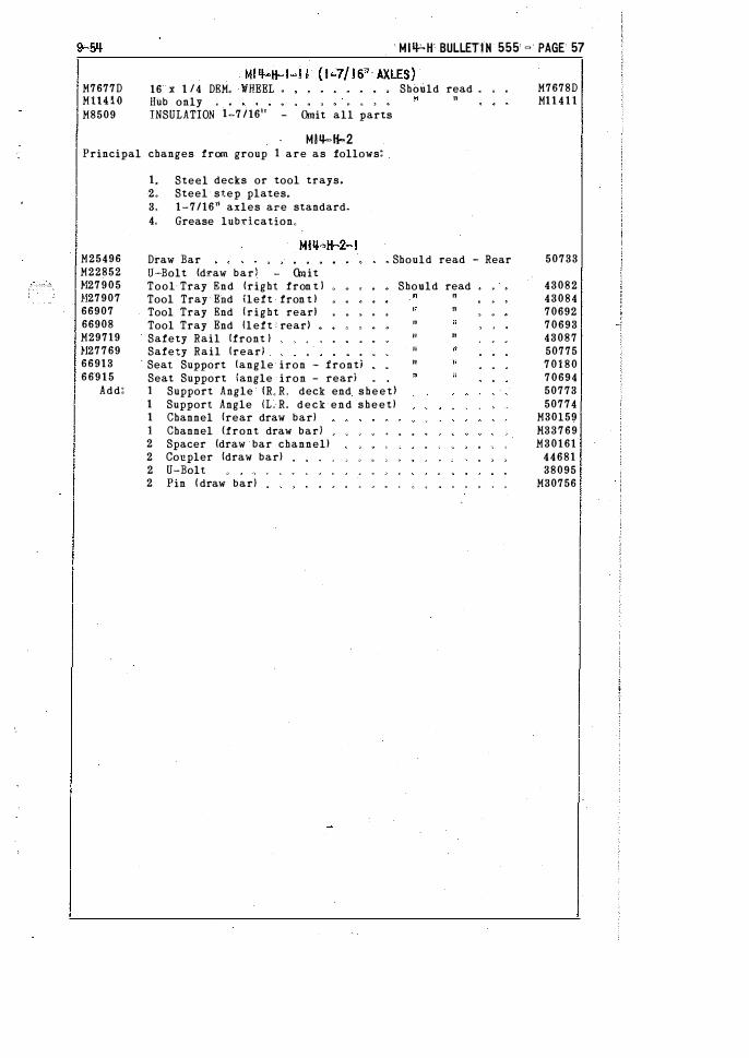
M7677D MllHO M8509
16 x 1 /4 DEM< liHEEL •
HUb only , , INSULATION 1-7 /161' - <Xnit all parts
M!q.,H-2 Principal changes from group 1 are as follows:
1. Steel decks or tool trays. 2. Steel step plates. 3. 1-7/1611 axles are standard. 4. Grease lubdcation"
MIQbH BULLETIN 555 � PAGE 57
ShOuld read • "
M7678D M11 4 1 1
M25496 M22852 1127905 !127907 66907 66908 M29719 !127769 66913 6 6 9 1 5
Draw Bar � Should read - Rear 50733
Add:
0-Bolt (d�aw bar} - Omit Tool- Tray End (right fron t } Tool Tray Elld ileft fron t ) Tool Tray End !right rear! Tool Tray End lleft · rear} Safety Rail (front ) Safety Rail !rear/ Seat Support !angle iron - front) Seat Support (angle iron - rearl 1 Support Angle {R" R' deck end sheet} 1 Support Angle IL. R, deck end sheet) 1 Channel !rear draw bar) 1 Channel (front draw bar) 2 Spacer (draw bar channel) 2 Co�pler !draw bar) 2 U-Bolt 2 Pin ( draw bar)
Should read " "
" "
" "
" ' "
43082 43084 70692 70693 43087 50775 7 0 1 8 0 70694 50773 50774
M30l59 1!33769 M30161
44681 38095
M30756