Service Connection Guidelines for Rural Water and Sewer ...
40
REGIONAL MUNICIPALITY OF WOOD BUFFALO RURAL WATER AND SEWER SERVICING (RWSS) SERVICE CONNECTION GUIDELINES REVISION 0 July 2020
Transcript of Service Connection Guidelines for Rural Water and Sewer ...

REGIONAL MUNICIPALITY OF WOOD BUFFALO
RURAL WATER AND SEWER SERVICING (RWSS)
SERVICE CONNECTION GUIDELINES
REVISION 0
July 2020

Page | i Last Update July 2020
Introduction
Table of Contents
Table of Contents ........................................................ i
1. Introduction ........................................................... 2
1.1. General ........................................................................................................................................ 2
1.2. Commercial and BUSINESS Industrial Lots .......................................................................... 3
1.3. Regulatory, Applications, Permits and Inspections ............................................................... 4
1.4. Site Plan....................................................................................................................................... 6
1.5. Contractors / Installers ............................................................................................................... 6
2. Full Pressure Water Service .................................. 7
2.1 Overview ........................................................................................................................................... 7
2.2 Material .............................................................................................................................................. 7
2.3 Installation ......................................................................................................................................... 7
2.4 Community Specific Requirements ............................................................................................... 8
3. Trickle Fill Water Service ....................................... 9
3.1 Overview ........................................................................................................................................... 9
3.2 Material .............................................................................................................................................. 9
3.3 Installation ....................................................................................................................................... 10
3.4 Community Specific Requirements ............................................................................................. 10
4. Gravity Sewer Service .......................................... 11
4.1 Overview ......................................................................................................................................... 11
4.2 Material ............................................................................................................................................ 11
4.3 Installation ....................................................................................................................................... 11
4.4 Standard Detail Drawings ............................................................................................................. 12

Page | ii Last Update July 2020
Introduction
5. Septic Tank Effluent Pumping (STEP) Sewer
Service ....................................................................... 13
5.1 Overview ......................................................................................................................................... 13
5.2 STEP System Suppliers ............................................................................................................... 13
5.3 Materials .......................................................................................................................................... 13
5.4 Installation ....................................................................................................................................... 15
5.5 Community Specific Requirements ............................................................................................. 16
5.6 Standard Detail Drawings ............................................................................................................. 16
Appendices .................................................................. i
Appendix A. Tank Sizing Charts .......................................................................................................... A
Appendix B. Sample Site Plan ............................................................................................................. B
Appendix C. Standard Drawings .......................................................................................................... C
Appendix D. RWSS Permit Requirements for Various Communities ............................................ D

Page | iii Last Update July 2020
Introduction
Abbreviations
Abbreviation Full Name
ASTM American Society for Testing and Materials ANSI American National Standards Institute CSA Canadian Standards Association CSE Confined Space Entry ESS RMWB’s Engineering Servicing Standards ESSDP RMWB’s Engineering Servicing Standards and Development Procedures HDPE High-Density Polyethylene HSE Health, Safety & Environment NSF National Sanitation Foundation PVC Polyvinyl Chloride RWSS Rural Water and Sewer Servicing SDR Standard Dimensional Ratio STEP Septic Tank Effluent Pump

Page | 2 Last Update July 2020
Introduction
1. Introduction
1.1.GENERAL
The purpose of the rural water and sewer servicing guidelines is to provide the minimum acceptable standards to follow to design and install water and sewer on private residential property in rural communities when connecting to the municipal sewer system. Property owners who request to connect to the municipal piped water and sewer systems are required to follow and adhere to this municipal guideline as the acceptable minimum standard.
The following are guidelines and not the complete design. The property owner is required to engage a certified contractor to design and install the system to follow these minimum guidelines while meeting the needs of the site specific constraints and dwelling size.
Any work completed on private property by the owners or their agents is the sole responsibility of the property owner. They are to apply sound engineering principles and industry best practices to provide an end product that is practical, economical, efficient, safe and sustainable. Work must be carried out in accordance with the current Occupational Health and Safety requirements.
The rural communities and the type of proposed water and sewer system covered by these guidelines include the following:
1. Saprae Creek Estateso Water – Previous to these upgrades there was a full pressure municipal water
distribution system with no fire flow in the community. With these upgrades thedistribution pipes are upgraded/upsized to accommodate fire flows with fire hydrantsin the community. No changes to the service connections on private property isrequired as the existing service connections will be connected to the new main.
o Sanitary Sewer – Previously there was no municipal sewer system in the community.Each property used a private sewage treatment method or a tank and haul system.With these upgrades a new Septic Tank Effluent Pumping (STEP) sewer system isinstalled at each lot to pump into the municipal sewer system ultimately going to theRMWB WWTP.
2. Drapero Water – Previous to these upgrades there was no municipal water system in the
community. Each property had a private water supply system or utilized hauling witha cistern for storage. With these upgrades a trickle fill water supply system is installedto distribute reliable potable water from the RMWB WTP into the water cistern at thehouse.
o Sanitary Sewer – Previously there was no municipal sewer system in the community.Each property used a private sewage treatment method or a tank and haul system.With these upgrades a new Septic Tank Effluent Pumping (STEP) sewer system isinstalled at each lot to pump into the municipal sewer system ultimately going to theRMWB WWTP.
3. Anzaco Water – Previously, Anzac had limited water service and a few fire hydrants within
the commercial areas. With these upgrades there will be full pressure water suppliedto each lot with fire flow and fire hydrants throughout the community.
o Sanitary Sewer – Previously, there were a few lots connecting directly to an existinglift station, however, there was no municipal sewer system to service the entirecommunity. Most properties used a private sewage treatment method or a tank andhaul system. With these upgrades the community will be serviced with a municipalgravity sewer system with the majority of lots having gravity sewer services, and afew lots with pumped services into the municipal main.

Page | 3 Last Update July 2020
Introduction
4. Gregoire Lake Estates
o Water – Previously Gregoire Lake Estates was not serviced by a municipal water distribution system. With these upgrades there will be full pressure water supply to each lot along with fire flow and fire hydrants throughout the community.
o Sanitary Sewer – Previously there was no municipal sewer system in the community. Each property used a private sewage treatment method or a tank and haul system. With these upgrades, the community will be serviced with a municipal gravity sewer system.
5. Janvier o Water – Apart from a few lots, previously Janvier was not serviced by a municipal
water distribution system. Water was trucked into each lot and stored in cisterns. With these upgrades, the community will be serviced by a municipal trickle fill water supply into the water cistern at the house.
o Sanitary Sewer – Previously Janvier was not serviced by a municipal sewer system. Wastewater was pumped out using hydrovac trucks. After this upgrade, Janvier will be serviced by a new Septic Tank Effluent Pumping (STEP) sewer system which will be installed at each lot to pump into a municipal sewer system.
6. Conklin o Water– Previously Conklin was not serviced by a municipal water distribution system.
Water was trucked into each lot and stored in cisterns. After this upgrade, Conklin will be serviced by a full pressure water supply system.
o Sanitary Sewer – Previously Conklin was not serviced by a municipal sewer system. Wastewater was pumped out using hydrovac trucks. After this upgrade, Conklin will be serviced by a municipal gravity sewer system with exception of 19 lots.
1.2. COMMERCIAL AND BUSINESS INDUSTRIAL LOTS
The RWSS Guidelines for Rural Water and Sewer Servicing are developed for residential lots. For lots that are zoned as Commercial or Business Industrial, owners should complete the following steps to connect to the newly constructed water and sanitary systems:
1. Consult with certified contractor/consultant to design the system based on specific needs of the house, keeping in view the subsurface and surface conditions of the lot.
2. Design and construct the system based on applicable bylaws, engineering servicing standards, regulations, and codes as noted, but not limited, in Section 1.3.1.
3. Ensure that backwater valves are provided in line with the requirements of the National Plumbing Code.
4. Ensure that hydrocarbon, grease and sediment traps are provided at all food processing establishments, shopping centers, service stations, car washes, hotels/motels, manufacturing, equipment servicing and cleaning facilities, institutions (churches, schools, etc.), and any other facilities that are expected to discharge sediment and/or grease, refer to ESSDP Sanitary Service Connections Section.
5. Ensure that certified contractor/consultant determines the need for any other additional pre-treatment system(s)/structure(s) and design the same in line with the discharge requirement of the Sanitary Sewer Utilities Bylaw and other applicable regulations and codes. It is the lot owners’ responsibility to provide the pre-treatment design.
6. Apply for all applicable permits. The permit must be pulled by the authorize person as noted in Section 1.3.2 below.

Page | 4 Last Update July 2020
Introduction
7. Install the service connections in accordance with the issued permits.
8. Get RWMB Safety Codes to inspect the installed connection before backfilling.
9. Get RMWB Safety Codes to perform final inspection and issue the permit service report.
1.3.REGULATORY, APPLICATIONS, PERMITS AND INSPECTIONS
1.3.1 Regulatory
The latest edition of all applicable regulations are to be followed, including but not limited to the Alberta Government, Alberta Environment and Parks and Safety Codes. The homeowner is to reference the Alberta Government and Alberta Environment and Parks websites and contact the RMWB for the latest regulatory regulations prior to installation.
Regulatory Item Web Link
Rural Area Water and Wastewater Service Connection Bylaw- 20/009
http://www.rmwb.ca/Municipal-Government/municipal_departments/Emergency-Services---Law-Enforcement/rcmp/Bylaw-Services/MunicipalBylaws.htm
RMWB’s Engineering Servicing Standards
http://www.rmwb.ca/living/Services-and-Utilities/Engineering-Servicing-Standards.htm
Alberta Safety Codes https://www.alberta.ca/safety-codes.aspx
Alberta Building Code https://www.alberta.ca/building-codes-and-standards.aspx
Alberta Fire Code https://www.alberta.ca/fire-codes-and-standards.aspx
Alberta Plumbing Code https://www.alberta.ca/plumbing-code-and-standards.aspx
Alberta Private Sewage Code https://www.alberta.ca/private-sewage-codes-and-standards.aspx
Alberta Private Sewer Systems https://www.alberta.ca/private-sewer-systems.aspx
Alberta Environment and Parks Standards and Guidelines for Municipal Waterworks
https://open.alberta.ca/publications/5668185
Alberta Wastewater and Storm Water Legislation
https://www.alberta.ca/wastewater-and-storm-water-legislation.aspx
Plumbing Safety Information Bulletin – STANDATA P-14-01-NPC15
https://open.alberta.ca/dataset/standata-plumbing-safety-information-bulletin/resource/56c2095b-4bd0-4163-8d8c-83120468cd86
RMWB Land Use Bylaw http://www.rmwb.ca/Municipal-Government/municipal_departments/Emergency-Services---Law-Enforcement/rcmp/Bylaw-Services/MunicipalBylaws/LandUse.htm
National Plumbing Code of Canada
https://nrc.canada.ca/en/certifications-evaluations-standards/codes-canada/codes-canada-publications/national-plumbing-code-canada-2015

Page | 5 Last Update July 2020
Introduction
RMWB Safety Codes Permitting Bylaw
https://www.rmwb.ca/Assets/Departments/Legislative+and+Legal+Services/Bylaws/Safety+Codes+Permitting+bylaw.pdf
RMWB Sanitary Sewer Utility Bylaw
https://www.rmwb.ca/Assets/Departments/Legislative+and+Legal+Services/Bylaws/Bylaw+85-51+-+Municipality$!e2$!80$!99s+Sanitary+Sewer+Utilities.pdf
RMWB Water Utilities Management Bylaw
https://www.rmwb.ca/Assets/Departments/Legislative+and+Legal+Services/Bylaws/WaterUtilitiesManagement.pdf
1.3.2 Sanitary and Water Applications, Permits and Inspections
Permits
All existing lots (residential as well as commercial/industrial) that have a development permit and building permits issued and that have water and sewer stubs already provided at the lots shall obtain the following permits. Please see Appendix D for the RWSS permit requirements specific to your community.
Permit Name Who will Issue and Inspect Who will Pull the Permit
Service Connection Permit (STEP)
Safety Codes Licensed Plumber or Certified Private Sewage System Installer
Service Connection Permit (DIRECT)
Safety Codes Licensed Plumber
Plumbing Permit Safety Codes Licensed Plumber
Electrical Permit Safety Codes Master Electricians
Water Meter Permit Water Meter Branch in Under Ground Utilities
Owner or the authorized Contractor
New development(s)/lot(s) or existing development(s)/lot(s) that require new connections to water and sewer service lines or want to redevelop the site must obtain other permits as noted in these Guidelines, the latest edition of Engineering Services Standards and Developmental Procedures, RMWB Land Use Bylaw and RMWB Safety Codes Permitting Bylaw.
Commissioning and Inspections
• Final commissioning and functional testing of the systems is to be completed by the certified contractorincluding infiltration or exfiltration testing of system and pressure testing of service lines is required.
• Final inspection by the RMWB or its representative is required of all buried and submerged equipment,tanks and piping. The Contractor is to ensure the tanks are empty prior to the inspection. Approvaland signoff of the system by the RMWB or its representative is required prior to backfill.

Page | 6 Last Update July 2020
Introduction
1.4.SITE PLAN
• The Owner is required to submit a site plan with the Service Connection Permit Application. The siteplan should provide information about location, size, dimensions, depth, slope and other details of thefollowing items:
a) Proposed sanitary sewer and water connections;b) Proposed sanitary septic tank and pump station locations;c) Existing building and driveways;d) Existing septic system;e) Existing water service locations or water wells (if any); andf) Existing water disposal systems/tanks.
• Sample site plan is included in Appendix A. An aerial photo is not required if it is not available.
1.5. CONTRACTORS / INSTALLERS
Under the RWSS program it is homeowner’s responsibility to hire a certified contractor to design and construct the service connections keeping in view specific requirement of the house and surface and subsurface constraints of the lot.
The homeowner shall make sure that the contractor has adequate knowledge and experience to complete the work as per these guidelines, applicable codes and regulations.
The contractor is responsible to supply and install all equipment and materials required to complete a fully functional and operational service connection.
For service connection under RWSS program the contractor shall be chosen from the latest list of “Private Sewage Systems Installer Certification List” maintained by Alberta Municipal Affairs.
The list can be accessed using the link below or searched on the World Wide Web using common search engine.
https://open.alberta.ca/publications/private-sewage-systems-installer-certification-list.

Page | 7 Last Update July 2020
Full Pressure Water Service
2. Full Pressure Water Service
2.1 OVERVIEW
The potable water service connection is the portion of the water system that runs from the municipal connection point to the building plumbing system, and generally includes the following:
• Water service pipe and fittings;• Water meter; and• Water pressure reducing valves may be required in some cases to reduce the pressure of the
water entering the building plumbing system.
2.2 MATERIAL
2.2.1 Piping
Refer to the National Plumbing Code for acceptable service piping materials. Minimum water service size for residential lots can be found in the Water Service Connection Section of RMWB’s Engineering Servicing Standards (ESS), latest edition.
Some residential dwellings like duplex, triplex and fourplexes may require different service connection sizes due to additional demands such as irrigation systems, fire sprinklers, and a higher number of fixtures. Each service should be designed according to the expected demand, maximum operating pressure of the system, and the equivalent fixture units according to the National Plumbing Code.
2.2.2 Water Service Fittings
Refer to the National Plumbing Code and RMWB ESS for acceptable fitting types and materials.
2.2.3 Water Meter
Water meters up to 100mm diameter shall be supplied by the Municipality and all other meters are to be supplied and installed by qualified plumber/contractor.
2.2.4 Water Pressure Reducing Valves
Direct-acting-water-pressure-reducing valves for domestic water supply systems, if required, shall conform to the requirements in the National Plumbing Code.
2.2.5 Bedding
Bedding material for pipes in sound dry soils is recommended to be Class B sand, conforming to the standard details and the gradation specified under water distribution section of RMWB’s ESS.
2.3 INSTALLATION
2.3.1 Water Service Piping and Fittings
• Any piping buried less than the frost depth is recommended to be insulated and/or heat traced.
2.3.2 Water Meter
• Water meter must be accessible with adequate clearance.• All water meters up to 100 mm will be issued by RMWB’s UGS/meter group and given to certified
contractor for installation. The meter group will assist or install meter up to 25 mm.

Page | 8 Last Update July 2020
Full Pressure Water Service
• All other meters are to be supplied and installed by a qualified plumber/contractor, subject to selectionreview, approval, inspection and operation by the Municipality. Refer to the Standard Detail Drawingsfor installation requirements.
2.3.3 Water Pressure Reducing Valves
• Pressure reducing valves may be required at some building’s plumbing system connections to the waterservice piping to protect the building plumbing from being over-pressurized. If the maximum operatingpressure from the municipal system at the point of connection exceeds the pressure rating of thebuilding plumbing system, a pressure reducing valve (PRV) is required to reduce the water pressure.It is required that the pressure reducing valve be installed within the building near the water meter.Refer to Community Specific Requirements for PRV requirements for each community below.
2.4 COMMUNITY SPECIFIC REQUIREMENTS
2.4.1 Saprae Creek
There is no need for installing new water meters. Existing water meters will be used.
2.4.2 Anzac
Normal operating pressures in the Anzac municipal water distribution system can be as high as 896 kPa (130 psi) when the fire pumps are running. Residential PRV’s are required for all homes.
2.4.3 Conklin
There is no need to install PRVs in Conklin.

Page | 9 Last Update July 2020
Trickle Fill Water Service
3. Trickle Fill Water Service
3.1 OVERVIEW
In a trickle feed water distribution system, a small-diameter distribution pipe supplies water to a private water storage facility (cistern) on each lot. With a small-diameter pipe and the ability to operate at lower pressures than conventional systems make this an economical alternative of providing domestic water distribution without fire suppression. However, the water quantity to each lot is controlled by a fixed rate. This system is appropriate for retrofitting existing rural areas currently served by truck fill water systems, as the trickle feed system can be plumbed into existing cisterns. Cisterns should be periodically cleaned and disinfected. Cistern maintenance/cleaning is the owner’s responsibility. Trickle feed service connection components are:
• Water service pipe;• Water service fittings;• Water meter pit; and• Water cistern.
3.2 MATERIAL
3.2.1 Piping
Refer to the National Plumbing Code for acceptable service piping materials. Minimum water service size for residential lots can be found in Water Service Connection Section of RMWB’s Engineering Servicing and Standards and Development Procedures (ESSDP), 2016.
Some residential dwellings like duplex, triplex and fourplexes may require different service connection sizes due to additional demands such as irrigation systems, fire sprinklers, and a higher number of fixtures. Each service should be designed according to the expected demand, maximum operating pressure of the system, and the equivalent fixture units according to the National Plumbing Code.
3.2.2 Water Service Fittings
Refer to the National Plumbing Code for acceptable fitting types and materials.
3.2.3 Bedding
Bedding material for pipes in sound dry soils is recommended to be Class B sand, conforming to the standard details and the gradation specified under water distribution section of RMWB’s ESS.
3.2.4 Meter Chamber
• A meter pit is to be installed at the property line of the lot.• A meter pit includes water meter (submergible under water), dual check valve, and ball valve.• Standard detail of the meter pit is included in drawing 3-3.
3.2.5 Water Cistern
The cisterns minimum requirements are as follows: • All cisterns are to be sized to provide a minimum of two (2) days storage of average day flow
requirements. The cistern size shall be determined according to anticipated users’ consumption, seetable 1 in Appendix A for recommended cistern sizes based on number of bedrooms.
• A float valve to control the flow into the cistern based on the water level.• It shall be watertight and leak proof.

Page | 10 Last Update July 2020
Trickle Fill Water Service
• The access hatch lid must be lockable and designed to prevent entry of surface water runoff andinsects, or vandalism, etc.
• A fill port should be used to prevent hoses, debris, and other contaminants from entering the cistern atthe time of refilling. Fill ports equipped with cam locks and screening are an option to prevent entry ofcontaminants into cisterns.
• The withdrawal pipe, which is the connection between the dwelling/business and the cistern, shall beinstalled approximately 10 to 15 centimeters (about 4 to 6 inches) above the bottom of the cistern. Thiswill reduce the possibility of sediment that collects at the bottom from entering the plumbing system.
• It shall be CSA and NSF approved.• A minimum 300mm air gap between the end of the service pipe and the high level of the water within
the water storage facility is required.
3.3 Installation
3.3.1 Water Service Piping and fittings
• For each approved service connection, the Municipality will provide a 25mm flow-controlled waterservice connection at a location no more than 300mm outside the Municipality’s right-of-way at a depthnot to exceed 3 meters. The service connection will entail a meter pit and flow control valve, restrictingflow to 0.5 US gpm (1.9 L/min).
• Installation of water service pipe shall follow the manufacturer’s recommendations.• All pipe installed with less than 3.0m cover will require insulation following the ESS details. If pipe is
installed with less than 3.0m cover using trenchless methods, pre-insulated pipe is to be installed, withthickness to be determined by the supplier and heat trace installed if insulation will not protect the pipefrom freezing.
3.3.2 Bedding
Bedding material for pipes in sound dry soils is recommended to be Class B sand, conforming to the standard details and the gradation specified in the RMWB ESS.
3.3.3 Water Meter
Refer to Section 2.3.2 for water meter details.
3.3.4 Water Cistern
• A cistern shall be installed according to the manufacturer’s recommendations.• In case of retrofitting an existing cistern, an assessment shall be carried out by a qualified
plumber/contractor. The assessment shall assess the structural/environmental conditions of theexisting cistern. Capacity shall be also included in the assessment.
• If the cistern is deemed to be suitable for retrofitting, the cistern shall be connected to the system by aqualified plumber/contractor.
3.4 Community Specific Requirements
3.4.1 Draper
Due to the elevation difference of the Draper Community, some lots are located too high to transfer sufficient domestic trickle service water and these lots will require a small booster pump station located conveniently to service the specific lots, check with RMWB for the lots list during the application process. The specific requirements of the booster pump will be provided to the homeowner upon submission of the service connection application for the certified contractor to install.

Page | 11 Last Update July 2020
Gravity Sewer Service
4. Gravity Sewer Service
4.1 OVERVIEW
A gravity sewer service generally consists of the following components: a) Sewer piping sloped downwards from the source towards the municipal sewer main that allows for
the free flow of sewage by gravity.b) Backwater valves may be installed on either the inside or outside of a building where the building
sewer exits the building towards the municipal sewer main. A backwater valve’s intent is to allowflow out of the building and prevent backflow of sewage into the building. It is recommended thatbackwater valves are checked and maintained regularly to ensure proper operation by thehomeowner.
c) Cleanouts are access points along the sewer pipe that allow for cleaning and inspection of theservice.
4.2 Material
4.2.1 Piping
Any pipe material classified for underground building sewer use in the National Plumbing Code is considered acceptable. If the service piping differs from the municipal connection or building piping, the fitting used to join the dissimilar pipe materials shall be designed to accommodate the required watertight transition. The service size shall not be less than 100mm diameter for single family dwellings. For commercial, industrial, institutional or multi-family areas, service piping shall not be less than 150mm diameter. In any case, services shall be designed appropriate for the expected flows from the development.
4.2.2 Backwater Valves
Backwater valves must meet the requirements of the Plumbing Code. Backwater valves must be of a normally open design to allow the passage of air under normal operating conditions.
4.2.3 Cleanouts
Cleanouts must meet the requirements of the National Plumbing Code.
4.2.4 Bedding
Bedding material for pipes in sound dry soils is recommended to be Class B sand, conforming to the standard details and the gradation specified under the RMWB’s ESS.
4.3 Installation
4.3.1 Pipe Slope
The service piping is recommended to be installed with a minimum downward slope of 2.0% in the direction of flow. Where this cannot be achieved, the minimum slope may be reduced to 1.0% provided the hydraulic load is within the limits identified in the National Plumbing Code.

Page | 12 Last Update July 2020
Gravity Sewer Service
4.3.2 Cleanouts
Cleanouts must be installed to permit cleaning of the entire service. On service piping that is at an angle of less than 45 degrees with the horizontal, cleanouts shall be installed at the spacing requirements shown in the table below. A cleanout permitting one-way rodding only allows for rodding in one direction. A cleanout permitting two-way rodding allows for rodding in both directions.
Table 4-1. Cleanout Spacing
Diameter of Service Pipe Maximum Spacing, m One-Way Rodding Two-Way Rodding
100mm 15 30 Over 100mm 26 52
It may be necessary to use fittings to accommodate changes in direction of the service line. Cleanouts on 150mm diameter and smaller services are required at every cumulative change in direction more than 45°. It is recommended that long radius bends be used for alignment changes. 90° elbows of 100mm diameter shall have a center-line radius greater than the diameter of the connecting pipe. Refer to the National Plumbing Code for more details. Cleanouts on sewer service piping 200mm or larger in diameter shall be manholes.
4.3.3 Backwater Valves
Backwater valves shall be installed in accordance with the requirements of the Plumbing Code. It is recommended that a backwater valve is installed in a location where it is easily accessible for maintenance. Backwater valves installed underground are recommended to allow for ground level access to remove the seat and gate from ground level regardless of depth.
4.3.4 Other
Roof leaders and building foundation drains are not permitted to be connected to the sanitary sewer service.
4.4 STANDARD DETAIL DRAWINGS
For service connection details, see standard drawings in Appendix B.

Page | 13 Last Update July 2020
Septic Tank Effluent Pumping Sewer Service
5. Septic Tank Effluent Pumping (STEP) Sewer Service
5.1 Overview
A STEP sewer service system is comprised of a two-compartment septic tank and pump system complete with a control. The sewage is discharged from the house to the septic tank, in which the primary treatment of sewage occurs. The pumping system pumps the effluent to the pressured or gravity mains and eventually to the municipal sewer system or a common collection point/septic field.
A STEP sewer service system generally consists of the following components: • A two compartment tank – the larger chamber of the tank is connected to the home and is where
the solids are settled, and the liquid flows over a weir to the smaller compartment of the tank wherethe effluent pump is located to pump to the municipal system.o The solids must be hydrovaced out of the larger solids compartment when they reach a
certain level. This level is set in the tank when it is installed, and the homeowner isresponsible for having the sludge removed.
• An effluent pump and filter, complete with two check valves (one in the pump assembly and one inthe hanging discharge assembly) and a rope/cable to pull the pump out from the surface.
• Piping connections from the home to the tank and from the pumps to the municipal serviceconnection at the street property line will be required.
• A control panel will automatically operate the pump and float switches to control the effluent levelsin the pump chamber.
• Power cables.
5.2 STEP System Suppliers
Orenco Systems or approved equal will be used for the STEP pumping systems for the RWMB Rural Servicing STEP installations. The contractor/installer is to follow all installation requirements provided by Orenco on their website here: https://www.orenco.com/applications/municipal/orenco-sewers https://odl.orenco.com/documents/NIM-EPS-1.pdf
The Installation Guide can be found here: https://odl.orenco.com/documents/NIM-EPS-1.pdf Operation and Maintenance information for the homeowner is provided on the website here:
• Troubleshooting - https://odl.orenco.com/documents/nch-efs-1.pdf• Clicktight and control panel - https://odl.orenco.com/documents/NIN-CLK-1.pdf• HDA-Style Discharge assemblies - https://odl.orenco.com/documents/NIN-HDA-1.pdf• Should a contractor propose a different pump the contractor shall provide all details with the
permit application.
5.3 Materials
5.3.1 Piping
• Service connections from the house to the tank and from the single compartment tank to the new pumpchamber shall be 100mm dia. DWV or Schedule 40 PVC pipe for all new pipe installed and is to havea positive slope of minimum 1%.
• Service connections from the effluent pump to the connection point near property line shall be 38mmHDPE DR 11, or approved equal as noted in ESS, except for Anzac (See Section 5.5 CommunitySpecific Requirements).
• Some residential dwellings like duplex, triplex and fourplexes may require different service connectionsizes due to a higher number of fixtures. Size of the service connection must be approved by the

Page | 14 Last Update July 2020
Septic Tank Effluent Pumping Sewer Service
Municipality during the permit process. • All connections to the tank are to be watertight as per the manufacturers specification.• For pre-approved pipe material specifications not included here, see the sewage service connection
section of the RMWB ESS.
5.3.2 Sanitary Service Fittings
• Fittings and other devices are to be compatible with the type of service pipe and suitable for themaximum operating pressure of the system.
• For pre-approved fitting specifications, refer to the RMWB ESS.
5.3.3 Bedding
• Bedding material for pipes in sound dry soil is recommended to be Class B sand, conforming to thestandard details and the gradation specified in the RMWB ESS.
5.3.4 Septic Tanks
The septic tanks are to be designed as follows: • The STEP system tank shall be a two-compartment septic tank.• The STEP system tank size shall be designed by the certified contractor based on the minimum
guidelines set out in the Tank Sizing Chart.• All necessary penetrations are to be watertight as per manufacturers specifications.• It shall be watertight and leak proof.• The access hatch lid must be bolted down or lockable and designed to prevent entry of surface water
runoff and insects, or vandalism, etc. The hatch is to conform to the requirements of the Alberta privatesewage system standard of practice (APSSOP).
5.3.5 Pump System
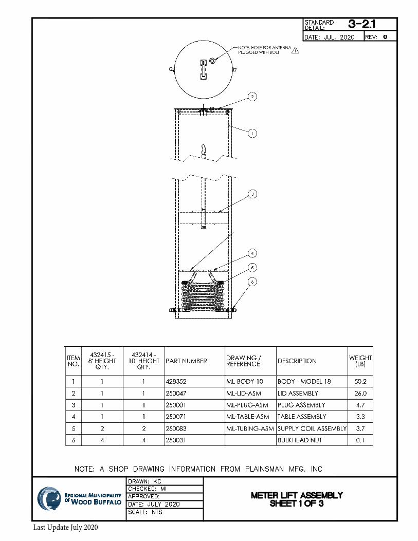
• The effluent pump shall be able to handle sewage effluent without exceeding manufacturer’srecommendations. The pump is specified to be the Orenco PF1005CV pumping system for all rural lotsexcept Janvier which will use PF1005 (refer to community specific guidelines) using a STEP system.
• The pump shall be equipped with a BioTube filter screen.• The lift out system will be able to provide access to the pump, motor, and filter from the surface.• The pump removal system is to be a hanging discharge assembly or similar to allow for easy removal
of pump and equipment.• Further details and parts of the system are included in the detail drawings in Appendix B.
5.3.6 Power and Controls
• The certified contractor is to provide the Orenco control panel and control system.• Installation shall be in accordance with the most recent version of the Canadian Electrical Code (CEC)
and acceptable to the Authority Having Jurisdiction (AHJ)• The control panel includes an Orenco MVP control panel mounted on a 100mm x 100mm treated wood
post or on the side of the house if in close enough proximity per the manufacturer.• The electrical feeder to the Orenco control panel is to be connected from the home (load side of the
electric meter) to the control panel• Where acceptable by the CEC and AHJ, the contractor shall be permitted to interrupt the feeders from
the load side of the meter to the consumer panel for the purpose of installing a splitter to feed both thehouse and the Orenco control panel provided that:
o All grounding and bonding are in accordance with Section 10 of the CEC.o System grounding of the grounded conductor (Neutral) shall only occur at one location
(meter socket or consumer panel). No more than one (1) system ground shall be present.

Page | 15 Last Update July 2020
Septic Tank Effluent Pumping Sewer Service
o System bonding jumper to the grounded conductor (neutral) shall only occur at the locationwhere the system ground is connected to the grounded conductor (neutral). No more thanone (1) system bond point shall be present.
o The Orenco pump and control panel system shall be bonded to ground through a suitablebonding means as defined by the CEC.
o Electrical disconnect for the Orenco system shall be located next to the splitter andelectrical meter and shall be lockable both on and off.
o Conductor sizes to re-feed the electrical meter from the splitter shall be of the same sizeas the existing wires that exist between the splitter and the consumer service.
o Tap conductor sizing from the splitter to the electrical disconnect and to the Orenco controlpanel shall be in accordance with Section 14 of the CEC.
o Electrical splitter shall be lockable and contain a utility seal / tag once final connections andmeasurements have been verified.
o No modifications are made to the existing lug configuration in the electrical meter.• Where the requirements listed above cannot be met for the installation of a splitter at the electrical
meter due to violations by the CEC or AHJ, the contractor shall be responsible for feeding the Orencopump and control panel by a branch circuit from the electrical panel inside the home, shop, or garage(whichever is the closest based on proximity and has the available capacity).
• The Orenco system operates on a single phase, 120 VAC circuit and has individual overcurrentprotection THE within the control panel for its control circuit (120 VAC, 10 Amp), and pumping circuit(120 VAC, 15 Amp).
• Contractor shall be responsible for providing a branch circuit(s) with conductors sized accordinglybased on the requirements of the CEC.
• Level control will be with three float switches for pump on, pump off, and high-level alarm.• The alarm system is to be a combination of both a visual and audible (greater than 80 dB).• Should a cellular alarm connection be desired by the homeowner, they are to state this in the application
package and the additional cost is to be covered by the homeowners.• A Test-Normal-Silence switch accessible from panel exterior is required.• Dry auxiliary contacts are required to allow connection to the building monitoring/security system.
5.4 Installation
5.4.1 Installation Practices
• It is recommended that all service piping, tanks, pumps and associated products are installed inaccordance with the manufacturer’s installation guidelines and all applicable codes.
5.4.2 Sewer Service Piping and Fittings
• For each approved service connection, a pipe stub will be provided by the Municipality at a location nomore than 300mm outside the Municipality’s right-of-way at varying depths, typically about 3m belowgrade.
• Horizontal separation between water and other services in the same trench is 0.3m for service with50mm diameter pipe and less, and 2.0m for services with a pipe diameter greater than 50 mm.
• All pipe installed with less than 3.0m cover will require insulation following the ESS details. If pipe isinstalled with less than 3.0m cover using trenchless methods, pre-insulated pipe is to be installed, withthickness to be determined by the supplier and heat trace installed if insulation will not protect the pipefrom freezing.

Page | 16 Last Update July 2020
Septic Tank Effluent Pumping Sewer Service
5.4.3 Effluent Tank and Pump System
• If retrofitting an existing septic tank, an assessment shall be carried out by a certified contractor. Theassessment shall review the structural / environmental conditions of the existing tank, and the capacityshall be also included in the assessment.
• If the septic tank is deemed to be suitable for retrofitting, the tank shall be connected to the system bya qualified plumber/contractor.
o If the existing tank is a single compartment, a new single compartment tank is to be installedper the design drawing details attached.
o The following modifications are required on the existing tank before putting in service:i. All sludge must be removed from the tank; andii. The septic tank must be waterproofed so that no ground water can enter the tank and
no sewage can exit the tank. This includes the access cover, penetrations and thetank itself.
• If the septic tank was deemed to be unsuitable for reuse, a new tank shall be installed according to therequirements in this section. The homeowner will be responsible to decommission the old tanks to meetregulatory requirements.
• The applicant shall use a certified contractor to install the tank and pump system service connection.
5.5 Community Specific Requirements
5.5.1 Anzac
The Anzac sewage collection system is primarily comprised of gravity sewer mains with a few exceptions as follows. There are three types of sewer services within Anzac:
1. Gravity sewer (majority of lots)2. Pumped sewer into gravity service pipe at property line where either a grinder pump or an effluent
pump capable of meeting the localized pumping head to convey flows to the service stub isacceptable.
3. STEP sewer (three lots along Highway 881). The contractor is to contact the RMWB to identify thespecific lots that will require a pumped system.
5.5.2 Conklin
The Conklin sewage collection system is primarily comprised of gravity sewer mains with the exception of the lots listed below. These lots are considerably lower than the fronting road and therefore not serviceable with full gravity system. The waste water from the these lots is to be collected in septic tanks and pumped into the gravity service pipe.
The contractor is to contact the RMWB to identify the specific lots that will require a pumped system.
5.6 STANDARD DETAIL DRAWINGS
For service connection details, see standard drawings in Appendix B.

Page | i Last Update July 2020
Appendices
Appendices

Page | A Last Update July 2020
Appendices
s
APPENDIX A. TANK SIZING CHARTS

Last Update July 2020

Table 1: Recommended Cistern Tank Size For Trickle Fill System
Required Cistern
Tank Volume
based on 2 days of
average day
demand
Additional
Operating
Volume (see
Note 2)
Total Working
Volume
(base +
additional)
Total Cistern
Tank
Operational
Volume
Num
ber o
f B
edro
oms
(BR
)
Per
sons
/BR
for
Res
iden
tial
Occ
upan
cype
r AP
SS
SO
P
Ave
rage
Dai
ly W
ater
Volu
me
as p
er E
SS
@ 3
60 L
iters
/P
erso
n/ D
ay i
n (L
)
Cal
cula
ted
from
5%
of T
otal
Wor
king
Vol
ume
+ 10
% to
allo
w fo
r 300
mm
air
gap
onto
p of
the
float
ing
valv
e
Tot
al C
iste
rn T
ank
Wor
king
Vol
ume
in
(L)
Tota
l Wor
king
Vol
ume
+Ad
ditio
nal O
pera
ting
Vol
ume
(L)
L imp. Gal.
2 2 2880 432 3312 3312 4600 1020
3 1.5 3240 486 3726 3726 4600 1020
4 1.5 4320 648 4968 4968 6900 1500
5 1.5 5400 810 6210 6210 6900 1500
6 1.5 6480 972 7452 7452 8150 1800
7 1.5 7560 1134 8694 8694 9100 2000
8 1.5 8640 1296 9936 9936 10442 2300
9 1.5 9720 1458 11178 11178 12300 2700
10 1.5 10800 1620 12420 12420 12300 3200
Notes:
Number of
Bedrooms and
Number of
Persons per
Bedroom
Recommended Tank size for
Base Working Volume without
additonal allowance (Confirm
Working and Pump Chamber
Volumes with manufacturer
1. Minimum Trickle fill cistern size is 2 days of average day demand, see ESS 7.20.3.22.Additional Operating Volume is calculated using 5% of the Total Working Volume (approximate unusable volume of bottom 100 mm of3. This table was created for use by the Municipality, any use by a third party is done so at their own risk.
Last Update July 2020

Page | B Last Update July 2020
Appendices
s
APPENDIX B. SAMPLE SITE PLAN

##E##E
##E!!P
!!P !!P""S
""S
""S
""S"u
53.5
53.48
170.45
150.
14
150.
14
268.
74
262.
77
Street Name
0 7.5 15 22.5 303.75Meters
COMMUNITY: SAPRAE CREEK ESTATES CIVIC ADDRESS: ### STREET NAME LOT: ##BLOCK: #PLAN: ### ####
CONSULTANT:CONSULTANT REP: CONTRACTOR: CONTRACTOR REP:
Legend
"u Sanitary Holding Tank
""S Sanitary Septic Tank
!!P Sanitary Pump
##E Sanitary Exit
Water MainsSanitary Service Stub
Sanitary MainsSanitary Septic FieldWater Lot Service
Power Lot ServicesGas Lot Services
DRAFT
Last Update July 2020
Extra drill pit

Page | C Last Update July 2020
Appendices
s
APPENDIX C. STANDARD DRAWINGS

℄
Last Update July 2020

℄
Last Update July 2020
Last Update July 2020

Last Update July 2020

Last Update July 2020

Last Update July 2020

PLAN
SECTION A-A
Last Update July 2020
JULY
AutoCAD SHX Text
CONNECT TO LOW PRESSURE SEWER RMWB DETAIL 5-910
AutoCAD SHX Text
RESIDENCE
AutoCAD SHX Text
BY HOME OWNER
AutoCAD SHX Text
BY OTHERS
AutoCAD SHX Text
RESIDENCE
AutoCAD SHX Text
LOW PRESSURE SANITARY FORCEMAIN
AutoCAD SHX Text
38mm HDPE SAN
AutoCAD SHX Text
EX SAN OR NEW 100mm PVC SDR28
AutoCAD SHX Text
BUILDING EXTERNAL WALL
AutoCAD SHX Text
LOW PRESSURE SANITARY FORCEMAIN OR GRAVITY MAIN
AutoCAD SHX Text
38mm HDPE SAN
AutoCAD SHX Text
38mm HDPESAN SERVICE
AutoCAD SHX Text
GENERAL NOTES: 1. CONTRACTOR TO FOLLOW ALL APPLICABLE MUNICIPAL BYLAWS AND CONTRACTOR TO FOLLOW ALL APPLICABLE MUNICIPAL BYLAWS AND REGULATORY CODES AND REQUIREMENTS 2. CONTRACTOR TO CONFIRM INSULATION REQUIREMENTS FOR EXISTING AND CONTRACTOR TO CONFIRM INSULATION REQUIREMENTS FOR EXISTING AND NEW TANKS AND TO ENSURE ADEQUATE MEASURES ARE TAKEN TO PROTECT AGAINST FREEZING 3. CONTRACTOR TO VERIFY ANTI-FLOATATION REQUIREMENTS FOR NEW TANKS CONTRACTOR TO VERIFY ANTI-FLOATATION REQUIREMENTS FOR NEW TANKS WITH TANK SUPPLIER. 4. SIZE OF THE SEPTIC TANK IS TO BE DESIGNED BY CERTIFIED SIZE OF THE SEPTIC TANK IS TO BE DESIGNED BY CERTIFIED CONTRACTOR BASED ON THE NUMBER OF BEDS AND 24 HOURS EMERGENCY STORAGE IN THE PUMPING CHAMBER. THE TABLE PROVIDED IS FOR INFORMATION PURPOSE ONLY. 5. UTILITY LOCATES AND WORKING WITH SUBSURFACE CONDITIONS AS THEY UTILITY LOCATES AND WORKING WITH SUBSURFACE CONDITIONS AS THEY ARE FOR EACH LOT ARE THE RESPONSIBILITY OF THE CONTRACTOR.
AutoCAD SHX Text
}
AutoCAD SHX Text
BUILDING EXTERNAL WALL
AutoCAD SHX Text
FINISHED GROUND
AutoCAD SHX Text
CONDUIT AND POWER FEED FROM ELECTRICAL DISCONNECT ON SPLITTER OR PANEL
AutoCAD SHX Text
100mm PVC SDR28 SANWITHIN 2.0m OF TANK
AutoCAD SHX Text
SEE STANDARD DRAWING 5-2 FOR SINGLE CHAMBER SEPTIC TANK SEE STANDARD DRAWING 5-3 FOR TWO CHAMBER SEPTIC TANK
AutoCAD SHX Text
6
AutoCAD SHX Text
7
AutoCAD SHX Text
1
AutoCAD SHX Text
2
AutoCAD SHX Text
2
AutoCAD SHX Text
3
AutoCAD SHX Text
4
AutoCAD SHX Text
5
AutoCAD SHX Text
5
AutoCAD SHX Text
6
AutoCAD SHX Text
8
AutoCAD SHX Text
100mm PVC SDR28 SANWITHIN 2.0m OF TANK
AutoCAD SHX Text
TIE-IN TO PIPE SUPPLIED WITH TANK
AutoCAD SHX Text
CONNECTION TO EX PRESSURE OR GRAVITY SERVICE
AutoCAD SHX Text
EX SAN OR NEW 100mm PVC SDR28
AutoCAD SHX Text
CONNECTION TO EX PRESSURE OR GRAVITY SERVICE
AutoCAD SHX Text
2. MAINLINE ADAPTA VALVE INSTALLED ON WASTEWATER LINE FROM DWELLING. MAINLINE ADAPTA VALVE INSTALLED ON WASTEWATER LINE FROM DWELLING. 3. UNDERGROUND ELECTRICAL CONDUIT TO PUMP CONTROL PANEL. UNDERGROUND ELECTRICAL CONDUIT TO PUMP CONTROL PANEL. 4. 89x89 PRESSURE TREATED WOODEN PEDESTAL FOR MOUNTING CONTROL PANEL. POST TO BE 89x89 PRESSURE TREATED WOODEN PEDESTAL FOR MOUNTING CONTROL PANEL. POST TO BE BURIED MIN 0.6m DEEP. CENTER OF CONTROL PANEL TO BE 1.2m ABOVE GROUND. . 5. MVP (STANDARD) CONTROL PANEL (EXTERNALLY MOUNTED). MVP (STANDARD) CONTROL PANEL (EXTERNALLY MOUNTED). 6. 40mm SCREENED ROCK. 40mm SCREENED ROCK. 7. INSULATE ANY PIPE <3.0m BELOW GROUND AS PER RMWB DETAIL 5-908. INSULATE ANY PIPE <3.0m BELOW GROUND AS PER RMWB DETAIL 5-908. 8. 38mm HDPE DR 11 PIPE. 38mm HDPE DR 11 PIPE. 9. ALL PIPE INSTALLED WITH LESS THAN 3.0m COVER WILL REQUIRE INSULATION ALL PIPE INSTALLED WITH LESS THAN 3.0m COVER WILL REQUIRE INSULATION FOLLOWING THE ESS DETAILS. IF PIPE IS INSTALLED WITH LESS THAN 3.0m COVER USING TRENCHLESS METHODS, PRE-INSULATED PIPE IS TO BE INSTALLED, WITH THICKNESS TO BE DETERMINED BY THE SUPPLIER
AutoCAD SHX Text
LEGEND AND SPECIFICATIONS 1. SINGLE PHASE, 120 VAC, POWER SUPPLY FOR PUMP (20 AMP) AND SINGLE PHASE, 120 VAC, POWER SUPPLY FOR PUMP (20 AMP) AND CONTROL CIRCUIT (10 AMP) FROM THE LOAD SIDE OF THE ELECTRICAL METER. REFER TO THE RWSS GUIDELINES FOR DETAILS ON WIRING FOR THE PUMP CONTROL SYSTEM FROM THE LOAD SIDE OF THE METER. ALL WIRING ARRANGEMENTS SHALL BE IN STRICT ACCORDANCE WITH THE CANADIAN ELECTRICAL CODE (CEC) AND AS APPROVED BY THE AUTHORITY HAVING JURISDICTION (AHJ).
AutoCAD SHX Text
TIE-IN TO PIPE SUPPLIED WITH TANK
AutoCAD SHX Text
PROPERTY LINE
AutoCAD SHX Text
PROPERTY LINE
AutoCAD SHX Text
5-1
AutoCAD SHX Text
REV:
AutoCAD SHX Text
STANDARD
AutoCAD SHX Text
SCALE: NTS
AutoCAD SHX Text
APPROVED:
AutoCAD SHX Text
DATE: DECEMBER 2009
AutoCAD SHX Text
CHECKED: HK
AutoCAD SHX Text
DRAWN: PM
AutoCAD SHX Text
DATE: DEC. 2009
AutoCAD SHX Text
DETAIL:
AutoCAD SHX Text
0
AutoCAD SHX Text
RWSS STEP SEWER SERVICE CONNECTION - FULL CROSS SECTION
AutoCAD SHX Text
DATE: August 2020August 2020
AutoCAD SHX Text
DRAWN: JTM
AutoCAD SHX Text
CHECKED: JRS
AutoCAD SHX Text
DATE: Aug. 2020Aug. 2020

SECTION A-A
PLAN
®
Last Update July 2020
AutoCAD SHX Text
}
AutoCAD SHX Text
FIBERGLASS GASKETED LID c/w STAINLESS STEEL BOLTS MODEL: FLD24G12
AutoCAD SHX Text
24" GRADE RING INSERT (GRI24)
AutoCAD SHX Text
ORENCO PUMP VAULT (PVU68-2419)
AutoCAD SHX Text
ORENCO P-FLOAT (MF1 P-20-CLK)
AutoCAD SHX Text
2 - 4" (100mm) ABS COUPLING (CAPPED OFF)
AutoCAD SHX Text
NEW PVC PIPE TO HAVE MIN 1.0% SLOPE. 100mm DIA PVC DWV OR SCH 40 PIPE TO BE USED WITHIN 2.0m OF TANK (FROM EXISTING TANK)
AutoCAD SHX Text
CONNECT TO EXISTING OUTLET PIPE
AutoCAD SHX Text
500 GALLON TANK (11008GMH)
AutoCAD SHX Text
EFFLUENT FILTER
AutoCAD SHX Text
ORENCO EFFLUENT PUMP (PF1005CV-CLK)
AutoCAD SHX Text
ORENCO HANGING DISCHARGE (HDAS24125ASLC)
AutoCAD SHX Text
24" ULTRA RIB PVC
AutoCAD SHX Text
ORENCO CLICKTIGHT (CLKP-M23-20-60-NA) (WIRES NOT SHOWN)
AutoCAD SHX Text
2 - 4" (100mm) ABS COUPLING CAPPED OFF
AutoCAD SHX Text
A
AutoCAD SHX Text
A
AutoCAD SHX Text
TREATMENT VOLUME
AutoCAD SHX Text
V-PARTITION WALL
AutoCAD SHX Text
EXISTING SINGLE COMPARTMENT TANK
AutoCAD SHX Text
TO CONTROL PANEL
AutoCAD SHX Text
BIOTUBE PUMP VAULT PUMP VAULT MODEL: PVU68-2419
AutoCAD SHX Text
EFFLUENT DISCHARGE
AutoCAD SHX Text
NOTES: 1. PUMP PACKAGE: ORENCO PSA10-AWS-AB (OR APPROVED EQUAL)PUMP PACKAGE: ORENCO PSA10-AWS-AB (OR APPROVED EQUAL)
AutoCAD SHX Text
100mm RIGID STYROFOAM INSULATION CUT TO FIT AND INSTALLED ON RISER c/w BRACKETS AS REQUIRED
AutoCAD SHX Text
EXISTING SINGLE COMPARTMENT TANK
AutoCAD SHX Text
5-2
AutoCAD SHX Text
REV:
AutoCAD SHX Text
STANDARD
AutoCAD SHX Text
SCALE: NTS
AutoCAD SHX Text
APPROVED:
AutoCAD SHX Text
DATE: DECEMBER 2009
AutoCAD SHX Text
CHECKED: HK
AutoCAD SHX Text
DRAWN: PM
AutoCAD SHX Text
DATE: DEC. 2009
AutoCAD SHX Text
DETAIL:
AutoCAD SHX Text
0
AutoCAD SHX Text
500 GALLON STEP TANK DETAIL FOR TYPICAL 1 CHAMBER SEPTIC TANK INSTALLATIONS
AutoCAD SHX Text
DATE: July 2020
AutoCAD SHX Text
DRAWN: JTM
AutoCAD SHX Text
CHECKED: JRS
AutoCAD SHX Text
DATE: Jul. 2020
AutoCAD SHX Text
NOTES: 1. PUMP PACKAGE: ORENCO PSA10-AWS-AB (OR APPROVED EQUAL) PUMP PACKAGE: ORENCO PSA10-AWS-AB (OR APPROVED EQUAL) 2. UTILITY LOCATES AND WORKING WITH SUBSURFACE CONDITIONS AS THEY UTILITY LOCATES AND WORKING WITH SUBSURFACE CONDITIONS AS THEY ARE FOR EACH LOT ARE THE RESPONSIBILITY OF THE CONTRACTOR

®
Last Update July 2020
AutoCAD SHX Text
EFFLUENT DISCHARGE
AutoCAD SHX Text
BIOTUBE PUMP VAULT PUMP VAULT MODEL: PV___-2419 (PVU SIZE TBC WITH MANUFACTURER)
AutoCAD SHX Text
ORENCO EFFLUENT PUMP MODEL: PF1005CV-20-CLK (OR APPROVED EQUAL)
AutoCAD SHX Text
VAULT INLET PORTS
AutoCAD SHX Text
FILTER CARTRIDGE
AutoCAD SHX Text
LEVEL CONTROL FLOAT ASSEMBLY MODEL: MF1 P-20-CLK
AutoCAD SHX Text
FLOW INDUCER
AutoCAD SHX Text
FLEXIBLE HOSE
AutoCAD SHX Text
DISCHARGE ASSEMBLY MODEL: HDAS24125ASLC
AutoCAD SHX Text
24" ULTRA RIB PVC RISER
AutoCAD SHX Text
FIBERGLASS GASKETED LID c/w STAINLESS STEEL BOLTS MODEL: FLD24G12
AutoCAD SHX Text
CLICKTIGHT CONNECTOR MODEL: CLKP-M23-20-60-NA
AutoCAD SHX Text
INLET TEE
AutoCAD SHX Text
24" ULTRA RIB PVC RISER
AutoCAD SHX Text
FIBERGLASS GASKETED LID c/w STAINLESS STEEL BOLTS MODEL: FLD24G12
AutoCAD SHX Text
SLOPE GROUND AWAY FROM RISER
AutoCAD SHX Text
TO CONTROL PANEL
AutoCAD SHX Text
100mm RIGID STYROFOAM INSULATION CUT TO FIT AND GLUED TO UNDERSIDE OF LID.
AutoCAD SHX Text
100mm RIGID STYROFOAM INSULATION CUT TO FIT AND INSTALLED IN RISER C/W BRACKETS AS REQUIRED
AutoCAD SHX Text
}
AutoCAD SHX Text
TANK MODEL WILL VARY BASED ON SIZE REQUIRED
AutoCAD SHX Text
5-3
AutoCAD SHX Text
REV:
AutoCAD SHX Text
STANDARD
AutoCAD SHX Text
SCALE: NTS
AutoCAD SHX Text
APPROVED:
AutoCAD SHX Text
DATE: DECEMBER 2009
AutoCAD SHX Text
CHECKED: HK
AutoCAD SHX Text
DRAWN: PM
AutoCAD SHX Text
DATE: DEC. 2009
AutoCAD SHX Text
DETAIL:
AutoCAD SHX Text
0
AutoCAD SHX Text
TYPICAL 2 CHAMBER SEPTIC TANK INSTALLATION DETAIL
AutoCAD SHX Text
DATE: July 2020July 2020
AutoCAD SHX Text
DRAWN: JTM
AutoCAD SHX Text
CHECKED: JRS
AutoCAD SHX Text
DATE: Jul. 2020Jul. 2020
AutoCAD SHX Text
NOTES: 1. UTILITY LOCATES AND WORKING WITH SUBSURFACE CONDITIONS AS THEY UTILITY LOCATES AND WORKING WITH SUBSURFACE CONDITIONS AS THEY ARE FOR EACH LOT ARE THE RESPONSIBILITY OF THE CONTRACTOR

Page | D Last Update July 2020
Appendices
s
APPENDIX D. RWSS PERMIT REQUIREMENTS FOR VARIOUS COMMUNITIES

www.rmwb.ca 1
Drawing 1: RWSS Permit RequirementsDraper and Janvier
Permit Name, Issuance /Inspection Who Can Pull the Permit
Service Connection Permit (STEP)(A-B) and (D-E)• Issued and Inspected by Safety Codes.
Licensed Plumber orCertified Private Sewage System Installer
Plumbing Permit May be Required If:1) B- C is new/not already constructed or2) Alteration to Internal Building Plumbing is required• Issued and Inspected by Safety Codes.
Licensed Plumber
Electric Permit• Issued and Inspected by Safety Codes
Master Electricians
Water Meter Permit• Issued and Installed by Underground Utilities or Water
Meter or Rural Operations.• Water meter Installed inside the building for Anzac,
Conklin and Gregoire Lake Estates.• In Draper and Janvier, Water meter installed in Meter
Chamber outside next to the property line.• Turning on Water and Low Pressure Sewer Valves.
Owner or Owner’s Contractor
Utility Connection Permit • Not Required for lots that already have Service Stubs S-A
and W-D• Required, besides above permits, for lots that do not
have Service Stubs S-A and W-D and needs toConnect/Tap to Main Lines
• Currently Issued and Inspected by UGS/Reviewed byEngineering. (Please See Drawing 4).
Owner or Owner’s contractor
BUILDING
Septic Tank and Pump
Water Main
Sanitary Main
AB
C
DE
Property LineProperty Line
Note: Water and Sanitary service lines are shown in separate trench for illustration purpose only. Water Cistern shown outside of building for illustration purpose only. STEP: Septic Tank Effluent Pump ; Water Cistern is shown outside, can be inside
W
S
Water Cistern
Low Pressure Sewer/STEP
Trickle Fill Water Service
Last Update July 2020

www.rmwb.ca 2
Drawing 2: RWSS Permit Requirements Anzac , Conklin and Gregoire Lake Estates
Permit Name, Issuance /Inspection Who Can Pull the Permit
Service Connection Permit (DIRECT)(A-B) and (D-E)• Issued and Inspected by Safety Codes.
Licensed Plumber
Plumbing Permit May be Required If:1) Alteration to Internal Building Plumbing is required• Issued and Inspected by Safety Codes.
Licensed Plumber
Electric Permit• Issued and Inspected by Safety Codes.
Master Electricians
Water Meter Permit• Issued and Installed by Underground Utilities or Water
Meter or Rural Operations.• Water meter Installed inside the building for Anzac,
Conklin and Gregoire Lake Estates.• In Draper and Janvier, Water meter installed in Meter
Chamber outside next to the property line.• Turning on Water and Low Pressure Sewer Valves.
Owner or Owner’s Contractor
Utility Connection Permit • Not Required for lots that already have Service Stubs
S-A and W-D• Required, besides above permits, for lots that do not
have Service Stubs S-A and W-D and needs toConnect/Tap to Main Lines
• Currently Issued and Inspected by UGS/Reviewed byEngineering. (Please See Drawing 4).
Owner or Owner’s Contractor
BUILDING
Water Main
Sanitary Main
A
B
D E
Property LineProperty Line
Note: Water and Sanitary service lines are shown in separate trench for illustration purpose only.
W
S
Gravity Sewers (Except for Hybrid Lots)
Full Pressure Water Service
Last Update July 2020

www.rmwb.ca 3
Drawing 3: RWSS Permit Requirements Saprae Creek Estates and
Hybrid Lots in Anzac and Conklin
Permit Name, Issuance /Inspection Who Can Pull the Permit
Service Connection Permit (STEP) (A-B) and (D-E)
• Issued and Inspected by Safety Codes.
Licensed Plumber orCertified Private Sewage System Installer
Plumbing Permit May be Required If:1) B- C is new/not already constructed or2) Alteration to Internal Building Plumbing is required• Issued and Inspected by Safety Codes.
Licensed Plumber
Electric Permit• Issued and Inspected by Safety Codes.
Master Electricians
Water Meter Permit• Issued and Installed by Underground Utilities or Water
Meter or Rural Operations.• Water meter Installed inside the building for Anzac,
Conklin and Gregoire Lake Estates.• In Draper and Janvier, Water meter installed in Meter
Chamber outside next to the property line.• Turning on Water and Low Pressure Sewer Valves.
(Owner or Owner’s Contractor
Utility Connection Permit • Not Required for lots that already have Service Stubs S-A
and W-D• Required, besides above permits. for lots that do not
have Service Stubs S-A and W-D and needs toConnect/Tap to Main Lines
• Currently Issued and Inspected by UGS/Reviewed byEngineering. (Please See Drawing 4).
Owner or Owner’s Contractor
BUILDING
Septic Tank
Water Main
Sanitary Main
AB
C
D
Property LineProperty Line
Note: Water and Sanitary service lines are shown in separate trench for illustration purpose only. STEP System: Septic Tank Effluent Pumping; Hybrid lots requiring STEP tank and pump
W
S
E
Full Pressure Water Service
Low Pressure Sewer/STEP
Last Update July 2020

www.rmwb.ca
Drawing 4: When Utility Connection Permit is Required
This lot has no stubs S-A and W-D. Utility Connection Permit on top of other permits will be required for this lot.Other RWSS Permits: Service Connection, Plumbing, Electrical and Water Meter Permit
BUILDING
AS
DW
New Lot
Obtain Utility Connection Permit before Connection/Tapping in these Main Lines.
Existing Lot
Utility Connection Permit not required for this lot.Other RWSS Permits : Service Connection, Plumbing, Electrical and Water Meter Permit
Last Update July 2020