
SERVICE CENTER MANUAL - Toolsmart USAsite.toolsmartusa.com/PDFs/manuals/spraytech/0512768… ·...
24
Printed in the U. S. A. 0104 • Form No. 0512768D SERVICE CENTER MANUAL PISTON PUMP AIRLESS SPRAYER FOR MODELS: IMPORTANT! THIS MANUAL IS INTENDED FOR AUTHORIZED SERVICE CENTERS ONLY AND SHOULD NOT BE USED FOR CONSUMER REFERENCE 1-800-746-6595 Wagner Technical Service 1770 Fernbrook Lane, Minneapolis, MN 55447 http://www.wagnerspraytech.com Visit us on the world wide web! W AGNER 9140 9140S 9150 9170 9190 9210 AMSPRA Y 1400 1550 1700 1900 2100 AMSPRA Y BY SPRA YTECH 1400 1600 SPRA YTECH APEX SERIES 1420 1620 1720 1920 2120 KREBS K2015 K2015S K3017 K4019 PRO FORCE PF23 PF25 PF33
Transcript of SERVICE CENTER MANUAL - Toolsmart USAsite.toolsmartusa.com/PDFs/manuals/spraytech/0512768… ·...
Printed in the U. S. A. 0104 • Form No. 0512768D
SERVICE CENTER MANUALPISTON PUMP AIRLESS SPRAYERFOR MODELS:
IMPORTANT!THIS MANUAL IS INTENDED FOR
AUTHORIZED SERVICE CENTERS ONLYAND SHOULD NOT BE USED FOR
CONSUMER REFERENCE
1-800-746-6595Wagner Technical Service
1770 Fernbrook Lane, Minneapolis, MN 55447
http://www.wagnerspraytech.comVisit us on the world wide web!
WAGNER9140
9140S9150917091909210
AMSPRAY14001550170019002100
AMSPRAY BYSPRAYTECH
14001600
SPRAYTECHAPEX SERIES
14201620172019202120
KREBSK2015
K2015SK3017K4019
PRO FORCEPF23PF25PF33

TABLE OF CONTENTSSAFETY . . . . . . . . . . . . . . . . . . . . . . . . . . . . . . . . . . . . . . 2-3INLET VALVE ASSEMBLY . . . . . . . . . . . . . . . . . . . . . . . . . . 4YOKE ASSEMBLY . . . . . . . . . . . . . . . . . . . . . . . . . . . . . . . . 5PRIME/SPRAY VALVE ASSEMBLY . . . . . . . . . . . . . . . . . . . 6FLIUD SECTION . . . . . . . . . . . . . . . . . . . . . . . . . . . . . . . . . 7MOTOR ASSEMBLY . . . . . . . . . . . . . . . . . . . . . . . . . . . . 8-10ECCENTRIC ASSEMBLY . . . . . . . . . . . . . . . . . . . . . . . 11-12PRESSURE SWITCH ASSEMBLY. . . . . . . . . . . . . . . . . 13-14TRANDUCER ASSEMBLY . . . . . . . . . . . . . . . . . . . . . . . . . 15RELAY KIT. . . . . . . . . . . . . . . . . . . . . . . . . . . . . . . . . . . . . 16PARTS LIST . . . . . . . . . . . . . . . . . . . . . . . . . . . . . . . . . 17-22DATE CODE LOCATION . . . . . . . . . . . . . . . . . . . . . . . . . . 22TROUBLESHOOTING . . . . . . . . . . . . . . . . . . . . . . . . . . . . 24
SAFETY PRECAUTIONSThis manual contains information which must be read andunderstood before using the equipment. When you come to anarea which has one of the following symbols, pay particularattention and make certain to heed the safeguard.
This symbol indicates a potential hazard which may causeserious injury or loss of life. Important safety informationwill follow.
This symbol indicates a potential hazard to you or to theequipment. Important information that tells how to preventdamage to the equipment or how to avoid causes of minorinjuries will follow.
SPECIAL NOTE ON THE FOLLOWING MODELS:AMSPRAY 1400 1550 AMSPRAY BY SPRAYTECH 1400 1600WAGNER 9140 9140S 9150SPRAYTECH APEX 1420 1620PRO FORCE PF23 PF25KREBS K2015 K2015STHE ABOVE UNITS ARE PROVIDED WITH A NON-RESETABLE THERMAL OVERLOAD.
SPECIAL NOTE ON THE FOLLOWING MODELS:AMSPRAY 1700 1900 2100WAGNER 9170 9190 9210SPRAYTECH APEX 1720 1920 2120PRO FORCE PF33KREBS K3019 K4019THE ABOVE UNITS ARE PROVIDED WITH AREPLACEABLE FUSE.
• Always disconnect the motor from the power supplybefore working on the equipment.
NOTE: The cause of the overload should be correctedbefore restarting.
CAUTION
CAUTION
NOTE: Notes give important information whichshould be given special attention.
CAUTION
WARNING
2 © 2001 Wagner Spray Tech - All rights reserved.
HAZARD: Injection injury - A high pressure paint streamproduced by this equipment can pierce the skinand underlying tissues, leading to seriousinjury and possible amputation. SEE APHYSICIAN IMMEDIATELY.
DO NOT TREAT AN INJECTION INJURY AS A SIMPLE CUT!Injection can lead to amputation. See a physician immediately.The maximum operating range of the gun is 2800PSI/193BAR fluid pressure.PREVENTION:
• NEVER aim the gun at any part of the body. • NEVER allow any part of the body to touch the fluid stream.
DO NOT allow body to touch a leak in the fluid hose.• NEVER put your hand in front of the gun. Gloves will not
provide protection against an injection injury.• ALWAYS lock the gun trigger, shut the pump off, and
release all pressure before servicing, cleaning the tip orguard, changing tip, or leaving unattended. Pressure willnot be released by turning off the motor. ThePRIME/SPRAY knob must be turned to PRIME to relievethe pressure. Refer to the PRESSURE RELIEFPROCEDURE described in the pump manual.
• ALWAYS keep the tip guard in place while spraying. Thetip guard provides some protection but is mainly a warningdevice.
• ALWAYS remove the spray tip before flushing or cleaningthe system.
• Paint hose can develop leaks from wear, kinking andabuse. A leak can inject material into the skin. Inspectthe hose before each use.
• NEVER use a spray gun without a trigger lock and triggerguard in place.
• All accessories must be rated at or above 2800 PSI/193BAR. This includes spray tips, guns, extensions, and hose.
HAZARD: EXPLOSION OR FIRE - Solvent and paint fumescan explode or ignite. Property damage and/orsevere injury can occur.
PREVENTION:• Provide extensive exhaust and fresh air introduction to keep
the air within the spray area free from accumulation offlammable vapors.
• Avoid all ignition sources such as static electric sparks,open flames, pilot lights, and hot objects. Connecting ordisconnecting power cords or working light switches canmake sparks.
• Do not smoke in spray area.• Fire extinguisher must be present and in good working order.• Place paint pump at a minimum of 3 feet (preferably more)
into a separate, well ventilated room from the spray objector at least 20 feet from the spray object in a well ventilatedarea (add more hose if necessary). Flammable vapors areoften heavier than air. Floor area must be extremely wellventilated. The paint pump contains arcing parts that emitspark and can ignite vapors.
• The equipment and objects in and around the spray areamust be properly grounded to prevent static sparks.
• Use only conductive or grounded high pressure fluid hose.Gun must be grounded through hose connections.
NOTE TO PHYSICIAN:Injection into the skin is a traumatic injury. It is importantto treat the injury as soon as possible. DO NOT delaytreatment to research toxicity. Toxicity is a concern withsome coatings injected directly into the blood stream.Consultation with a plastic surgeon or reconstructivehand surgeon may be advisable.
WARNING
© 2001 Wagner Spray Tech - All rights reserved. 3
• Power cord must be connected to a grounded circuit.• Always flush unit into a separate metal container, at low
pump pressure, with spray tip removed. Hold gun firmlyagainst side of container to ground container and preventstatic sparks.
• Follow the material and solvent manufacturer's warningsand instructions.
• Use extreme caution when using materials with a flashpointbelow 70° F (21° C). Flashpoint is the temperature that afluid can produce enough vapors to ignite.
• Plastic can cause static sparks. Never hang plastic toenclose a spray area. Do not use plastic drop clothswhen spraying flammable materials.
• Use lowest possible pressure to flush equipment.GAS ENGINE (WHERE APPLICABLE)Always place pump outside of structure in fresh air. Keep allsolvents away from the engine exhaust. Never fill fuel tank witha running or hot engine. Hot surface can ignite spilled fuel.Always attach ground wire from pump unit to a grounded object,such as a metal water pipe. Refer to enigine owner’s manualfor complete safety information.
HAZARD: EXPLOSION HAZARD DUE TO INCOMPATIBLEMATERIALS - Will cause property damage orsevere injury.
PREVENTION:• Do not use materials containing bleach or chlorine.• Do not use halogenated hydrocarbon solvents such as
bleach, mildewcide, methylene chloride and 1,1,1 -trichloroethane. They are not compatible with aluminum.
• Contact your coating supplier about the compatibility ofmaterial with aluminum.
HAZARD: HAZARDOUS VAPORS - Paints, solvents,insecticides, and other materials can beharmful if inhaled or come in contact with thebody. Vapors can cause severe nausea,fainting, or poisoning.
PREVENTION:• Use a respirator or mask if vapors can be inhaled. Read
all instructions supplied with the mask to be sure it willprovide the necessary protection.
• Wear protective eyewear.
• Wear protective clothing as required by coatingmanufacturer.
HAZARD: GENERAL - can cause severe injury orproperty damage.
PREVENTION:• Read all instructions and safety precautions before
operating equipment.• Follow all appropriate local, state, and national codes
governing ventilation, fire prevention, and operation. • The United States Government Safety Standards have
been adopted under the Occupational Safety and HealthAct (OSHA). These standards, particularly part 1910 ofthe General Standards and part 1926 of the ConstructionStandards should be consulted.
• Use only manufacturer authorized parts. User assumesall risks and liabilities when using parts that do not meetthe minimum specifications and safety requirements of thepump manufacturer.
• Before each use, check all hoses for cuts, leaks, abrasionor bulging of cover. Check for damage or movement ofcouplings. Immediately replace the hose if any of theseconditions exist. Never repair a paint hose. Replace itwith another grounded high-pressure hose.
• All hoses, swivels, guns, and accessories must bepressure rated at or above 2800PSI/193 BAR.
WARNING
• Do not spray outdoors on windy days.• Wear clothing to keep paint off skin and hair.
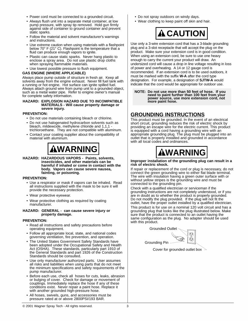
Use only a 3-wire extension cord that has a 3-blade groundingplug and a 3-slot receptacle that will accept the plug on theproduct. Make sure your extension cord is in good condition.When using an extension cord, be sure to use one heavyenough to carry the current your product will draw. Anundersized cord will cause a drop in line voltage resulting in lossof power and overheating. A 14 or 12 gauge cord isrecommended. If an extension cord is to be used outdoors, itmust be marked with the suffix W-A after the cord typedesignation. For example, a designation of SJTW-A wouldindicate that the cord would be appropriate for outdoor use.
GROUNDING INSTRUCTIONSThis product must be grounded. In the event of an electricalshort circuit, grounding reduces the risk of electric shock byproviding an escape wire for the electric current. This productis equipped with a cord having a grounding wire with anappropriate grounding plug. The plug must be plugged into anoutlet that is properly installed and grounded in accordancewith all local codes and ordinances.
Improper installation of the grounding plug can result in arisk of electric shock.If repair or replacement of the cord or plug is necessary, do notconnect the green grounding wire to either flat blade terminal.The wire with insulation having a green outer surface with orwithout yellow stripes is the grounding wire and must beconnected to the grounding pin.Check with a qualified electrician or serviceman if thegrounding instructions are not completely understood, or if youare in doubt as to whether the product is properly grounded.Do not modify the plug provided. If the plug will not fit theoutlet, have the proper outlet installed by a qualified electrician.This product is for use on a nominal 120 volt circuit and has agrounding plug that looks like the plug illustrated below. Makesure that the product is connected to an outlet having thesame configuration as the plug. No adapter should be usedwith this product.
Grounded Outlet
Grounding Pin
Cover for grounded outlet box
WARNING
NOTE: Do not use more than 50 feet of hose. If youneed to paint further than 100 feet from yourpower source, use more extension cord, notmore paint hose.
CAUTION

INLET VALVE ASSEMBLY (all models)
1. If the unit will not prime, simply tap the outside of the inlet with a mallet or tap the ball itself byremoving the suction set and inserting a small probe into the inlet of the pump. If the problem isthe result of a stuck ball, this may solve the problem. If the problem continues, proceed withreplacing the inlet assembly as described in the next step.
2. Lay unit on its side.3. Unscrew inlet assembly and remove.4. Inspect for dry paint or damaged ball.• Clean if paint is preventing inlet ball from moving freely (shake back and forth)• Clean with warm soapy water or mineral spirits• Replace inlet assembly if cleaning will not work or ball/seat is damaged
5. Add light oil or grease to the O-ring, and slip new o-ring on inlet assembly.6. Screw new inlet valve with o-ring attached onto the pump housing.
REWORKING THE INLET VALVE1. Unscrew the inlet valve assembly from the unit with an adjustable wrench. 2. Unscrew the inlet nut using a 3/8 inch allen wrench.3. Remove excess paint or rust from the ball or seat or replace with new parts from kit (see part numbers). You may also have to
clean excess paint inside the housing.4. Inspect the inlet O-ring on the inlet valve. Clean or replace, and lubricate with a light household oil.5. Reassemble ball, carbide seat, and O-rings in the order shown below into the inlet valve.6. Install inlet nut back into the inlet valve. Torque to 12 ± 2 ft-lbs if you have a torque wrench.7. Make sure the inlet valve O-ring is installed on the inlet valve, then install entire inlet valve assembly back into the
housing. Tighten with an adjustable wrench.
Inlet valve
Inlet O-ring
Ball
O-ring
Carbide seat
O-ring
Inlet nut
Inlet valve assembly P/N 0512222Models:
Wagner9140
9140S9150
Amspray140015009150
KrebsK2015
K2015S
SprayTechApex14201620
Inlet valve assembly P/N 0512224Models:
Wagner917091909210
Amspray170019002100
SprayTechApex172019202120
Pro ForcePF23PF25
Amsprayby SprayTech
14001600
Pro ForcePF33
KrebsK3017K4019
Inlet valve assembly
Inlet nut
FAILURE: Unit will not prime, unit loses pressure or unit won't maintain pressureTOOLS REQUIRED: Adjustable wrench or 1.5 inch (1 inch for certain models) open end wrench
4 © 2001 Wagner Spray Tech - All rights reserved.
The part numbers for these kits are located on the PartsLists at the end of this manual.
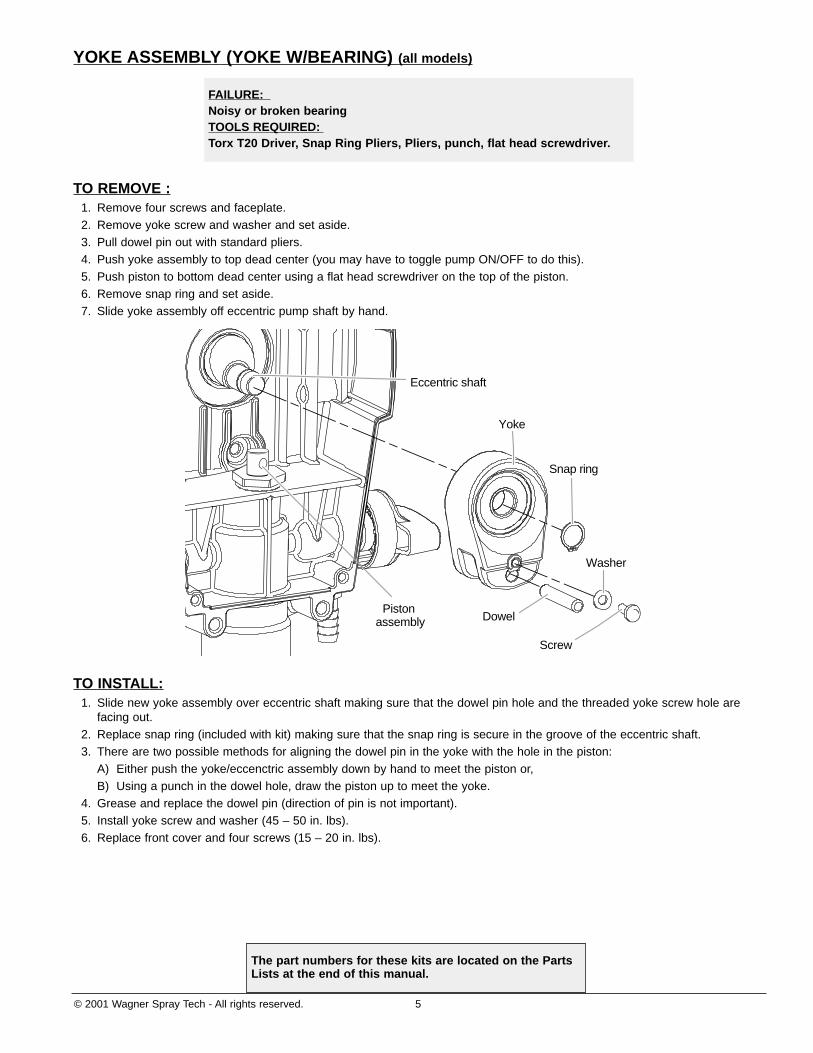
YOKE ASSEMBLY (YOKE W/BEARING) (all models)
TO REMOVE :1. Remove four screws and faceplate.2. Remove yoke screw and washer and set aside.3. Pull dowel pin out with standard pliers.4. Push yoke assembly to top dead center (you may have to toggle pump ON/OFF to do this).5. Push piston to bottom dead center using a flat head screwdriver on the top of the piston.6. Remove snap ring and set aside.7. Slide yoke assembly off eccentric pump shaft by hand.
TO INSTALL:1. Slide new yoke assembly over eccentric shaft making sure that the dowel pin hole and the threaded yoke screw hole are
facing out.2. Replace snap ring (included with kit) making sure that the snap ring is secure in the groove of the eccentric shaft.3. There are two possible methods for aligning the dowel pin in the yoke with the hole in the piston:
A) Either push the yoke/eccenctric assembly down by hand to meet the piston or,B) Using a punch in the dowel hole, draw the piston up to meet the yoke.
4. Grease and replace the dowel pin (direction of pin is not important).5. Install yoke screw and washer (45 – 50 in. lbs).6. Replace front cover and four screws (15 – 20 in. lbs).
Dowel
Screw
Washer
Snap ring
Yoke
Piston assembly
Eccentric shaft
FAILURE: Noisy or broken bearingTOOLS REQUIRED: Torx T20 Driver, Snap Ring Pliers, Pliers, punch, flat head screwdriver.
© 2001 Wagner Spray Tech - All rights reserved. 5
The part numbers for these kits are located on the PartsLists at the end of this manual.
6 © 2001 Wagner Spray Tech - All rights reserved.
The part numbers for this kit are located on the PartsLists at the end of this manual.
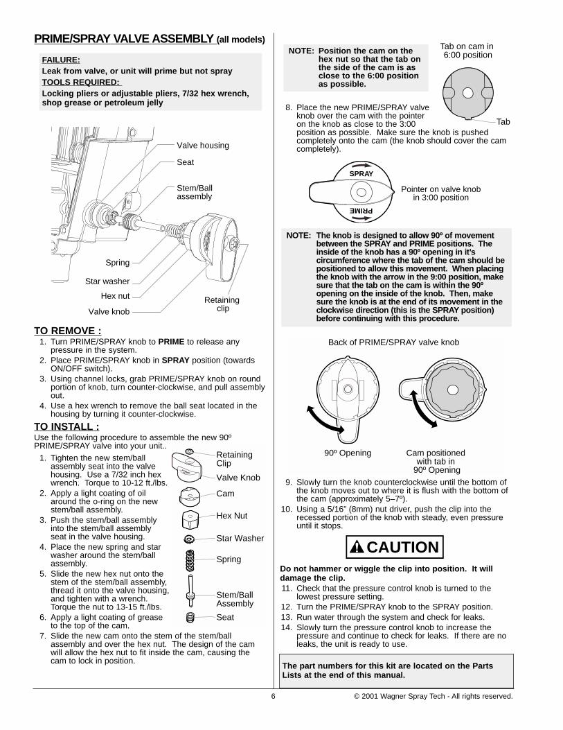
8. Place the new PRIME/SPRAY valveknob over the cam with the pointeron the knob as close to the 3:00position as possible. Make sure the knob is pushedcompletely onto the cam (the knob should cover the camcompletely).
9. Slowly turn the knob counterclockwise until the bottom ofthe knob moves out to where it is flush with the bottom ofthe cam (approximately 5–7º).
10. Using a 5/16” (8mm) nut driver, push the clip into therecessed portion of the knob with steady, even pressureuntil it stops.
Do not hammer or wiggle the clip into position. It willdamage the clip. 11. Check that the pressure control knob is turned to the
lowest pressure setting.12. Turn the PRIME/SPRAY knob to the SPRAY position.13. Run water through the system and check for leaks.14. Slowly turn the pressure control knob to increase the
pressure and continue to check for leaks. If there are noleaks, the unit is ready to use.
CAUTION
Back of PRIME/SPRAY valve knob
90º Opening Cam positioned with tab in
90º Opening
NOTE: The knob is designed to allow 90º of movementbetween the SPRAY and PRIME positions. Theinside of the knob has a 90º opening in it’scircumference where the tab of the cam should bepositioned to allow this movement. When placingthe knob with the arrow in the 9:00 position, makesure that the tab on the cam is within the 90ºopening on the inside of the knob. Then, makesure the knob is at the end of its movement in theclockwise direction (this is the SPRAY position)before continuing with this procedure.
SPRAY
PRIME
Pointer on valve knobin 3:00 position
NOTE: Position the cam on thehex nut so that the tab onthe side of the cam is asclose to the 6:00 positionas possible.
Tab
Tab on cam in 6:00 position
PRIME/SPRAY VALVE ASSEMBLY (all models)
TO REMOVE :1. Turn PRIME/SPRAY knob to PRIME to release any
pressure in the system.2. Place PRIME/SPRAY knob in SPRAY position (towards
ON/OFF switch).3. Using channel locks, grab PRIME/SPRAY knob on round
portion of knob, turn counter-clockwise, and pull assemblyout.
4. Use a hex wrench to remove the ball seat located in thehousing by turning it counter-clockwise.
TO INSTALL :Use the following procedure to assemble the new 90ºPRIME/SPRAY valve into your unit..
1. Tighten the new stem/ballassembly seat into the valvehousing. Use a 7/32 inch hexwrench. Torque to 10-12 ft./lbs.
2. Apply a light coating of oilaround the o-ring on the newstem/ball assembly.
3. Push the stem/ball assemblyinto the stem/ball assemblyseat in the valve housing.
4. Place the new spring and starwasher around the stem/ballassembly.
5. Slide the new hex nut onto thestem of the stem/ball assembly,thread it onto the valve housing,and tighten with a wrench.Torque the nut to 13-15 ft./lbs.
6. Apply a light coating of greaseto the top of the cam.
7. Slide the new cam onto the stem of the stem/ballassembly and over the hex nut. The design of the camwill allow the hex nut to fit inside the cam, causing thecam to lock in position.
SPRAY
PRIME
Valve Knob
Cam
Hex Nut
Star Washer
Spring
Stem/BallAssembly
Seat
RetainingClip
Stem/Ball assembly
Seat
Valve housing
Spring
Star washer
Hex nut Retaining clipValve knob
FAILURE:Leak from valve, or unit will prime but not sprayTOOLS REQUIRED: Locking pliers or adjustable pliers, 7/32 hex wrench,shop grease or petroleum jelly

© 2001 Wagner Spray Tech - All rights reserved. 7
SERVICE NOTE--MODELS 9210, 2100The inlet check ball is a wear part. Erosion of the checkball can result in a loss of performance similar to a wornpiston and seals. Inspect the inlet ball by removing theinlet valve assembly. If worn, replace the assembly withP/N 0512224.
The part numbers for these kits are located on the PartsLists at the end of this manual.
FLUID SECTION (all models)
Allow the pump to build pressure and shut off. Inspect thepiston/yoke assembly by removing the four screws that hold thefront cover.
• If the piston/yoke moves to top dead center when pumpshuts off, the lower seal/piston or outlet valve has failed.
• If the piston/yoke travels to bottom dead center, the valveball/seat in the inlet valve and the inlet valve should be replaced.
TO REMOVE:1. Remove the suction set.2. Remove the front cover and the four screws that secure it
using a T20 Torx head driver. 3. Remove the yoke screw and washer that secures the dowel
pin. The dowel pin connects the yoke to the piston.4. Using the pliers, pull the dowel pin out.
5a. For Amspray models 1400, 1550:Amspray by SprayTech models 1400, 1600:Wagner models 9140, 9140S, 9150:SprayTech Apex models 1420, 1620: ProForce models PF23 and PF25:Krebs models K2015, K2015S:Rotate the pump shaft so the piston is in the top dead centerposition. This can be done by pushing on the yoke. This isrequired to disassemble all the parts.
5b. For all other models, inspect the yoke assembly andpiston. In order to remove all the necessary parts, the pistonmust not be in the bottom dead center position. If the pistonis at the bottom of the stroke, install the front cover andscrews, turn the pump on briefly to index the piston, unplugthe unit, and repeat step 2.
6. Unscrew and remove the inlet valve assembly using anadjustable wrench.
7. Remove the piston assembly by pushing down on the pistonnear the yoke.
8. Unscrew and remove the top nut using and adjustable wrench. 9. Remove the worn seals using a flat head screwdriver or
punch. Remove the bottom seal from the bottom bypressing against the side of the seal and popping it out.Remove the top seal from the bottom by pressing on thebottom of the seal and popping it out the top of the housing.Be sure not to scratch the housing where the seals arelocated.
10. Clean the area where the new seals are to be installed.
TO INSTALL:1. Lubricate the new top seal with Wagner Separating Oil (P/N
0154908) or light household oil and by hand place the seal(cup side of seal down) into the top port of the housing.
2. Place a small amount of anti-seize on the threads of the nut.Place the top nut into the top of the housing and tighten withan adjustable wrench. This will drive the top seal into thecorrect position.
3. Turn the pump upside down.Lubricate the seal on thepiston/seal assembly similar tothe top seal. Place thepiston/seal assembly into thebottom of the housing. Insertthe plastic insertion tool andthread into position to properlyseat the piston/seal. Threadfully until tight. Remove the
FAILURE: Unit will not prime or maintain pressure TOOLS REQUIRED: T20 Torx driver, adjustable wrench, flat head screwdriver,rubber mallet
insertion tool.4. Install the new O-ring on the inlet valve assembly, lubricate
with Separating Oil (P/N 0154908), thread into the bottom(inlet) of the housing, and tighten with an adjustable wrench.This will drive the bottom seal into the correct position.
5. Align the piston with the yoke. A rubber mallet may be used.Be careful not to damage the piston.
6. Apply any type of household grease to the piston and yokearea to prolong life. Apply to the holes in the yoke wherethe dowel is inserted.
7. Install the dowel pin to connect the yoke to the piston. Thepiston may have to be moved up or down to do this.
8. Install the yoke screw and washer to secure the dowel pin.9. Turn pump right side up and apply a few drops of Wagner
Separating Oil or light household oil between the top nut andpiston. This will prolong the seal life.
10. Install front cover and four (4) screws.11. Install the suction set.
DowelScrew
Fluidsectionkit
Fluidsectionkit
Washer
Retainingring
Yoke
Piston/sealassembly
Top seal(cup down)
Top nut
O-ring
Inlet valve assembly
CAUTION! DO NOTattempt to remove theseals from the piston.
Insertiontool
8 © 2001 Wagner Spray Tech - All rights reserved.
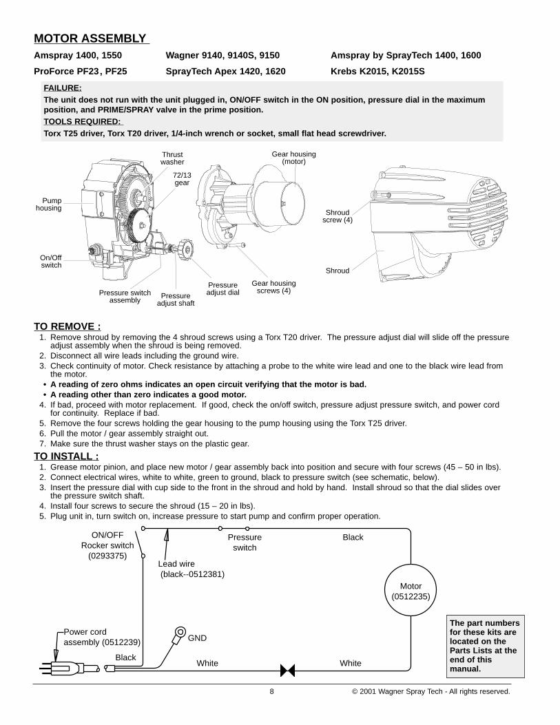
MOTOR ASSEMBLYAmspray 1400, 1550 Wagner 9140, 9140S, 9150 Amspray by SprayTech 1400, 1600
ProForce PF23, PF25 SprayTech Apex 1420, 1620 Krebs K2015, K2015S
TO REMOVE :1. Remove shroud by removing the 4 shroud screws using a Torx T20 driver. The pressure adjust dial will slide off the pressure
adjust assembly when the shroud is being removed.2. Disconnect all wire leads including the ground wire.3. Check continuity of motor. Check resistance by attaching a probe to the white wire lead and one to the black wire lead from
the motor.• A reading of zero ohms indicates an open circuit verifying that the motor is bad.• A reading other than zero indicates a good motor.
4. If bad, proceed with motor replacement. If good, check the on/off switch, pressure adjust pressure switch, and power cordfor continuity. Replace if bad.
5. Remove the four screws holding the gear housing to the pump housing using the Torx T25 driver.6. Pull the motor / gear assembly straight out.7. Make sure the thrust washer stays on the plastic gear.
TO INSTALL :1. Grease motor pinion, and place new motor / gear assembly back into position and secure with four screws (45 – 50 in lbs).2. Connect electrical wires, white to white, green to ground, black to pressure switch (see schematic, below).3. Insert the pressure dial with cup side to the front in the shroud and hold by hand. Install shroud so that the dial slides over
the pressure switch shaft.4. Install four screws to secure the shroud (15 – 20 in lbs).5. Plug unit in, turn switch on, increase pressure to start pump and confirm proper operation.
ON/OFFRocker switch
(0293375)
Power cord assembly (0512239)
Motor(0512235)
Pressureswitch
Black
Lead wire (black--0512381)
BlackWhite White
GND
Thrustwasher
72/13gear
Gear housing(motor)
Gear housingscrews (4)
Pressureadjust dialPressure
adjust shaftPressure switch
assembly
Pumphousing
On/Offswitch
Shroudscrew (4)
Shroud
FAILURE:The unit does not run with the unit plugged in, ON/OFF switch in the ON position, pressure dial in the maximumposition, and PRIME/SPRAY valve in the prime position.TOOLS REQUIRED: Torx T25 driver, Torx T20 driver, 1/4-inch wrench or socket, small flat head screwdriver.
The part numbersfor these kits arelocated on theParts Lists at theend of thismanual.

© 2001 Wagner Spray Tech - All rights reserved. 9
MOTOR ASSEMBLYAmspray 1700, 1900 Wagner 9170, 9190
ProForce PF33 SprayTech Apex 1720, 1920 Krebs K3017, K4019
TO REMOVE :1. Remove shroud by removing the 4 shroud screws. 2. Remove 8 Amp fuse by turning gray fuse holder cap 1/8 turn counter-clockwise and inspect. Replace if necessary.3. Remove red and black motor leads from relay.4. Check continuity of motor. Check resistance by attaching a probe to the red and black motor leads.• A reading of zero ohms indicates an open circuit verifying that the motor is bad.• A reading other than zero indicates a good motor.
5. If bad, proceed with motor replacement. If good, check the on/off switch, pressure adjust pressure switch, and power cordfor continuity. Replace if bad.
6. Disconnect green ground wire, red pressure switch wires from relay, black power wire from the fuse holder, white power cordwire from relay and black wire from fuse holder to relay (see schematic below).
7. Remove fuse holder from motor baffle.8. Remove the four screws holding the gear housing to the pump housing using a Torx T25.9. Pull the motor / gear assembly straight out.
TO INSTALL :1. Grease motor pinion and place new motor / gear assembly back into position and secure with four screws (45 – 50 in lbs).2. Connect electrical wires (see schematic, below).3. Insert the pressure dial with cup side to the front in the shroud and hold by hand. Install shroud so that the dial slides over
the pressure switch shaft.4. Install four screws to secure the shroud (15 – 20 in lbs).5. Plug unit in, turn switch on, increase pressure to start pump and confirm proper operation.
GND
Fuse(Fuse holder)
Pressure switch
SP1 SP1
SP2
SP2
SP3SP4 SP4
SP5
SP5
SP3
Power cord
Relay
Motorassembly
BLA
CK
RE
D
BLACK
BLACKRED
RED
WHITE
ON/OFF Rockerswitch
Relay screwRelay
Gear housing screw (4)
99/13 gear(under housingand not shown)
Pumphousing
Fuse
Shroud
Shroud screw
Gear housing(motor)
Fuse holder
FAILURE:The unit does not run with the unit plugged in, ON/OFF switch in the ON position, pressure dial in the maximumposition, and PRIME/SPRAY valve in the prime position.TOOLS REQUIRED: Torx T25 driver, Torx T20 driver, 1/4-inch wrench or socket, small flat head screwdriver.
The part numbers for these kits are located on the PartsLists at the end of this manual.
10 © 2001 Wagner Spray Tech - All rights reserved.
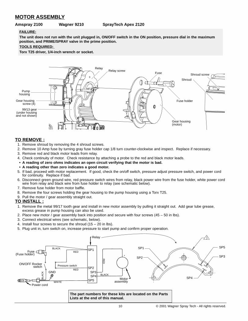
MOTOR ASSEMBLYAmspray 2100 Wagner 9210 SprayTech Apex 2120
TO REMOVE :1. Remove shroud by removing the 4 shroud screws. 2. Remove 10 Amp fuse by turning gray fuse holder cap 1/8 turn counter-clockwise and inspect. Replace if necessary.3. Remove red and black motor leads from relay.4. Check continuity of motor. Check resistance by attaching a probe to the red and black motor leads.• A reading of zero ohms indicates an open circuit verifying that the motor is bad.• A reading other than zero indicates a good motor.
5. If bad, proceed with motor replacement. If good, check the on/off switch, pressure adjust pressure switch, and power cordfor continuity. Replace if bad.
6. Disconnect green ground wire, red pressure switch wires from relay, black power wire from the fuse holder, white power cordwire from relay and black wire from fuse holder to relay (see schematic below).
7. Remove fuse holder from motor baffle.8. Remove the four screws holding the gear housing to the pump housing using a Torx T25.9. Pull the motor / gear assembly straight out.
TO INSTALL :1. Remove the metal 99/17 tooth gear and install in new motor assembly by pulling it straight out. Add gear lube grease,
excess grease in pump housing can also be used.2. Place new motor / gear assembly back into position and secure with four screws (45 – 50 in lbs).3. Connect electrical wires (see schematic, below).4. Install four screws to secure the shroud (15 – 20 in lbs).5. Plug unit in, turn switch on, increase pressure to start pump and confirm proper operation.
GND
Fuse(Fuse holder)
Pressure switch
SP1 SP1
SP2
SP2
SP3SP4 SP4
SP5
SP5
SP3
Power cord
Relay
Motorassembly
BLA
CK
RE
D
BLACK
BLACKRED
RED
WHITE
ON/OFF Rocker switch
Relay screwRelay
Gear housing screw (4)
99/13 gear(under housingand not shown)
Pumphousing
Fuse
Shroud
Shroud screw
Gear housing(motor)
Fuse holder
FAILURE:The unit does not run with the unit plugged in, ON/OFF switch in the ON position, pressure dial in the maximumposition, and PRIME/SPRAY valve in the prime position.TOOLS REQUIRED: Torx T25 driver, 1/4-inch wrench or socket.
The part numbers for these kits are located on the PartsLists at the end of this manual.
© 2001 Wagner Spray Tech - All rights reserved. 11
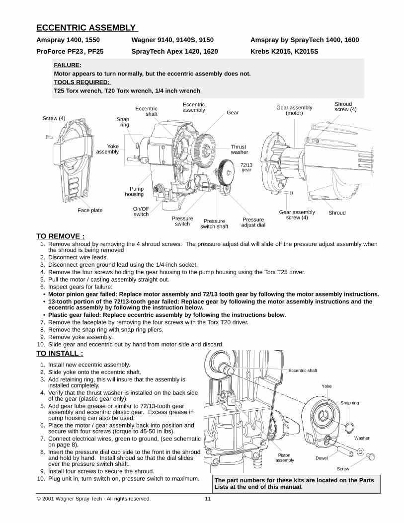
ECCENTRIC ASSEMBLYAmspray 1400, 1550 Wagner 9140, 9140S, 9150 Amspray by SprayTech 1400, 1600
ProForce PF23, PF25 SprayTech Apex 1420, 1620 Krebs K2015, K2015S
TO REMOVE :1. Remove shroud by removing the 4 shroud screws. The pressure adjust dial will slide off the pressure adjust assembly when
the shroud is being removed 2. Disconnect wire leads.3. Disconnect green ground lead using the 1/4-inch socket.4. Remove the four screws holding the gear housing to the pump housing using the Torx T25 driver.5. Pull the motor / casting assembly straight out.6. Inspect gears for failure:• Motor pinion gear failed: Replace motor assembly and 72/13 tooth gear by following the motor assembly instructions.• 13-tooth portion of the 72/13-tooth gear failed: Replace gear by following the motor assembly instructions and the
eccentric assembly by following the instruction below.• Plastic gear failed: Replace eccentric assembly by following the instructions below.
7. Remove the faceplate by removing the four screws with the Torx T20 driver.8. Remove the snap ring with snap ring pliers.9. Remove yoke assembly.
10. Slide gear and eccentric out by hand from motor side and discard.
TO INSTALL :
1. Install new eccentric assembly.2. Slide yoke onto the eccentric shaft.3. Add retaining ring, this will insure that the assembly is
installed completely.4. Verify that the thrust washer is installed on the back side
of the gear (plastic gear only).5. Add gear lube grease or similar to 72/13-tooth gear
assembly and eccentric plastic gear. Excess grease inpump housing can also be used.
6. Place the motor / gear assembly back into position andsecure with four screws (torque to 45-50 in lbs).
7. Connect electrical wires, green to ground, (see schematicon page 8).
8. Insert the pressure dial cup side to the front in the shroudand hold by hand. Install shroud so that the dial slidesover the pressure switch shaft.
9. Install four screws to secure the shroud.10. Plug unit in, turn switch on, pressure switch to maximum.
Dowel
Screw
Washer
Snap ring
Yoke
Piston assembly
Eccentric shaft
Eccentricassembly
Pressureswitch shaft
Pressureadjust dial
Eccentricshaft
Yokeassembly
Pumphousing
On/Offswitch
Snapring
Gear
Pressureswitch
Thrustwasher
72/13gear
Gear assembly(motor)
Shroudscrew (4)
Gear assemblyscrew (4)
Shroud
Screw (4)
Face plate
FAILURE:Motor appears to turn normally, but the eccentric assembly does not.TOOLS REQUIRED: T25 Torx wrench, T20 Torx wrench, 1/4 inch wrench
The part numbers for these kits are located on the PartsLists at the end of this manual.

12 © 2001 Wagner Spray Tech - All rights reserved.
ECCENTRIC ASSEMBLYAmspray 1700, 1900, 2100 Wagner 9170, 9190, 9210
ProForce PF33 SprayTech Apex 1720, 1920, 2120 Krebs K3017, K4019
TO REMOVE :1. Remove shroud by removing the 4 shroud screws. The pressure adjust dial will slide off the pressure adjust assembly when
the shroud is being removed (For Amspray model 2100, Wagner model 9210 and SprayTech Apex model 2120, thepressure adjust dial is located in the front of the face plate and will not be affected by the removal of the shroud).
2. Disconnect wire leads.3. Disconnect green ground lead using the 1/4-inch socket.4. Remove the four screws holding the gear housing to the pump housing using the Torx T25 driver.5. Pull the motor / casting assembly straight out.6. Inspect gears for failure:• Motor pinion gear failed: Replace motor assembly and 99/17 tooth gear by following the motor assembly instructions.• 17 tooth portion of the 99/17 tooth gear failed: Replace gear by following the motor assembly instructions• Main housing gear (99/17) failed: Replace eccentric gear housing assembly by following the instructions below.
7. Remove the faceplate by removing the four screws with the Torx T20 driver.8. Remove the snap ring with snap ring pliers.9. Remove yoke assembly.
TO INSTALL :
1. Slide yoke onto the eccentric shaft.2. Add retaining ring, this will insure that the assembly is
installed completely.3. Add gear lube grease or similar to 99/17 tooth gear
assembly. Excess grease in pump housing can also beused.
4. Place the motor / gear assembly back into position andsecure with four screws (torque to 45-50 in lbs).
5. Connect electrical wires, green to ground, (seeschematic on page 9 or 10, depending upon modelnumber).
6. Insert the pressure dial cup side to the front in theshroud and hold by hand. Install shroud so that the dialslides over the pressure switch shaft.
7. Install four screws to secure the shroud.8. Plug unit in, turn switch on, pressure switch to
maximum.Dowel
Screw
Washer
Snap ring
Yoke
Piston assembly
Eccentric shaft
Screw
Yokeassembly
Snapring
Eccentric gearhousing assembly
99/17 gear
Thrust washer
Gear assembly(motor)
Shroudscrew (4)
Pressureadjust dial
Gear assemblyscrew (4) Shroud
ON/OFF switch
Pressure switch shaft
Pressure switchFace plate
FAILURE:Motor appears to turn normally, but the eccentric assembly does not.TOOLS REQUIRED: T25 Torx wrench, T20 Torx wrench, 1/4 inch wrench
The part numbers for these kits are located on the PartsLists at the end of this manual.
© 2001 Wagner Spray Tech - All rights reserved. 13
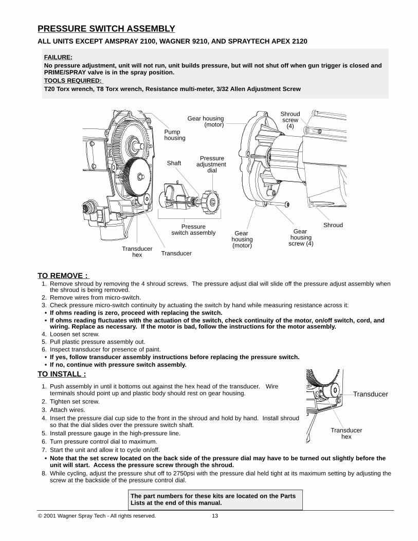
PRESSURE SWITCH ASSEMBLYALL UNITS EXCEPT AMSPRAY 2100, WAGNER 9210, AND SPRAYTECH APEX 2120
TO REMOVE : 1. Remove shroud by removing the 4 shroud screws. The pressure adjust dial will slide off the pressure adjust assembly when
the shroud is being removed.2. Remove wires from micro-switch.3. Check pressure micro-switch continuity by actuating the switch by hand while measuring resistance across it:• If ohms reading is zero, proceed with replacing the switch.• If ohms reading fluctuates with the actuation of the switch, check continuity of the motor, on/off switch, cord, and
wiring. Replace as necessary. If the motor is bad, follow the instructions for the motor assembly.4. Loosen set screw.5. Pull plastic pressure assembly out.6. Inspect transducer for presence of paint.• If yes, follow transducer assembly instructions before replacing the pressure switch.• If no, continue with pressure switch assembly.
TO INSTALL :
1. Push assembly in until it bottoms out against the hex head of the transducer. Wireterminals should point up and plastic body should rest on gear housing.
2. Tighten set screw.3. Attach wires.4. Insert the pressure dial cup side to the front in the shroud and hold by hand. Install shroud
so that the dial slides over the pressure switch shaft.5. Install pressure gauge in the high-pressure line.6. Turn pressure control dial to maximum.7. Start the unit and allow it to cycle on/off.• Note that the set screw located on the back side of the pressure dial may have to be turned out slightly before the
unit will start. Access the pressure screw through the shroud.8. While cycling, adjust the pressure shut off to 2750psi with the pressure dial held tight at its maximum setting by adjusting the
screw at the backside of the pressure control dial.
Transducer
Transducerhex
Gear housing(motor)
Pressureadjustment
dial
Pressureswitch assembly
TransducerTransducer
hex
Shaft
Gear housing
screw (4)
Pump housing
Shroud
Shroudscrew
(4)Gear housing
(motor)
FAILURE:No pressure adjustment, unit will not run, unit builds pressure, but will not shut off when gun trigger is closed andPRIME/SPRAY valve is in the spray position.TOOLS REQUIRED: T20 Torx wrench, T8 Torx wrench, Resistance multi-meter, 3/32 Allen Adjustment Screw
The part numbers for these kits are located on the PartsLists at the end of this manual.

14 © 2001 Wagner Spray Tech - All rights reserved.
PRESSURE SWITCH ASSEMBLYAmspray 2100 Wagner 9210 SprayTech Apex 2100
TO REMOVE : 1. Remove shroud by removing the 4 shroud screws.
2. Remove front cover by removing the 4 face plate screws.
3. Remove wires from micro-switch.
4. Check pressure switch continuity by actuating the switch by hand while measuring resistance across it:
• If ohms reading is zero, proceed with replacing the switch.• If ohms reading fluctuates with the actuation of the switch, check continuity of the motor, on/off switch, cord, and
wiring. Replace as necessary. If the motor is bad, follow the instructions for the motor assembly.
5. Remove 5/64” set screw and pull stem and pressure switch assembly outfrom the rear of the unit. Remove snap ring and O-ring and slide stem (withgear) out of the pressure switch assembly. Replace stem (with gear) into anew switch and return to pump.
TO INSTALL :1. Using a 5/64 Allen wrench install the new pressure switch assembly to the
transducer assembly.2. Insert pressure stem assembly (Gear/Shaft) through port behind face place.3. Install plastic gear using a 1/16 Allen wrench (pressure control stem should
be flush with back of plastic gear).4. Attach wires.5. Install pressure control knob.6. Install front cover by installing the 4 face plate screws.7. Install motor shroud by installing the 4 motor shroud screws.8. Install pressure guage in the high-pressure line.9. Turn pressure control dial to maximum.
10. Start the unit and allow it to cycle ON/OFF.• Note that the set screw located on the back side of the pressure dial may have to be turned out slightly before the
unit will start. Access the pressure screw through the shroud.11. While cycling, adjust the pressure shut off to 2750psi with the pressure dial held tight at its maximum setting by adjusting the
screw at the backside of the pressure control dial.
Adjustment hole
Shroud
Gearhousing(motor)
Pressure switchassembly
Pump housing
Transducer
Plastic gear
Pressureadjust stem
Pressureadjust dial
Frontcover
FAILURE:No pressure adjustment, unit will not run, unit builds pressure, but will not shut off when gun trigger is closed andPRIME/SPRAY valve is in the spray position.TOOLS REQUIRED: T20 Torx wrench, 1/16 inch Allen wrench, T8 Torx wrench, Snap ring pliers, Resistance multi-meter, 3/32 Allenadjustment screw
The part numbers for these kits are located on the PartsLists at the end of this manual.
© 2001 Wagner Spray Tech - All rights reserved. 15
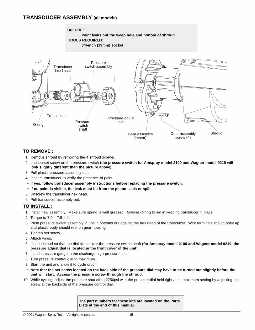
TRANSDUCER ASSEMBLY (all models)
TO REMOVE : 1. Remove shroud by removing the 4 shroud screws. 2. Loosen set screw on the pressure switch (the pressure switch for Amspray model 2100 and Wagner model 9210 will
look slightly different than the picture above)..3. Pull plastic pressure assembly out.4. Inspect transducer to verify the presence of paint.• If yes, follow transducer assembly instructions before replacing the pressure switch.• If no paint is visible, the leak must be from the piston seals or spill.
5. Unscrew the transducer hex head.6. Pull transducer assembly out.
TO INSTALL :1. Install new assembly. Make sure spring is well greased. Grease O-ring to aid in keeping transducer in place.2. Torque to 7.0 – 7.5 ft lbs.3. Push pressure switch assembly in until it bottoms out against the hex head of the transducer. Wire terminals should point up
and plastic body should rest on gear housing.4. Tighten set screw.5. Attach wires.6. Install shroud so that the dial slides over the pressure switch shaft (for Amspray model 2100 and Wagner model 9210, the
pressure adjust dial is located in the front cover of the unit). 7. Install pressure gauge in the discharge high-pressure line.8. Turn pressure control dial to maximum.9. Start the unit and allow it to cycle on/off.• Note that the set screw located on the back side of the pressure dial may have to be turned out slightly before the
unit will start. Access the pressure screw through the shroud.10. While cycling, adjust the pressure shut off to 2750psi with the pressure dial held tight at its maximum setting by adjusting the
screw at the backside of the pressure control dial.
Pressure adjustdialPressure
switchshaft
Transducer
Pressureswitch assemblyTransducer
hex head
Gear assembly(motor)
Gear assemblyscrew (4)
Shroud
O-ring
FAILURE:Paint leaks out the weep hole and bottom of shroud.
TOOLS REQUIRED: 3/4-inch (19mm) socket
The part numbers for these kits are located on the PartsLists at the end of this manual.
16 © 2001 Wagner Spray Tech - All rights reserved.
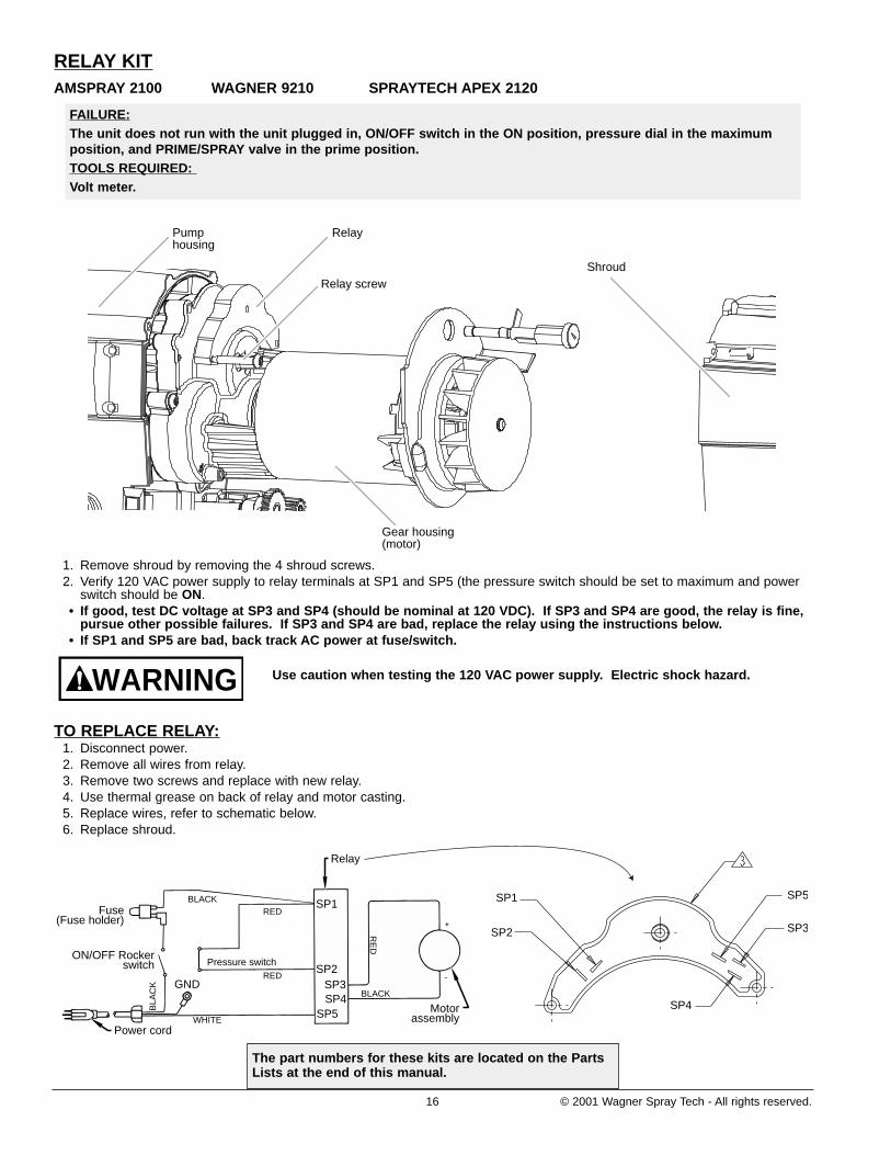
RELAY KITAMSPRAY 2100 WAGNER 9210 SPRAYTECH APEX 2120
1. Remove shroud by removing the 4 shroud screws. 2. Verify 120 VAC power supply to relay terminals at SP1 and SP5 (the pressure switch should be set to maximum and power
switch should be ON.• If good, test DC voltage at SP3 and SP4 (should be nominal at 120 VDC). If SP3 and SP4 are good, the relay is fine,
pursue other possible failures. If SP3 and SP4 are bad, replace the relay using the instructions below. • If SP1 and SP5 are bad, back track AC power at fuse/switch.
Use caution when testing the 120 VAC power supply. Electric shock hazard.
TO REPLACE RELAY:1. Disconnect power.2. Remove all wires from relay.3. Remove two screws and replace with new relay. 4. Use thermal grease on back of relay and motor casting.5. Replace wires, refer to schematic below. 6. Replace shroud.
GND
Fuse(Fuse holder)
Pressure switch
SP1 SP1
SP2
SP2
SP3SP4 SP4
SP5
SP5
SP3
Power cord
Relay
Motorassembly
BLA
CK
RE
D
BLACK
BLACKRED
RED
WHITE
ON/OFF Rockerswitch
WARNING
Relay screw
Pumphousing
Relay
Shroud
Gear housing(motor)
FAILURE:The unit does not run with the unit plugged in, ON/OFF switch in the ON position, pressure dial in the maximumposition, and PRIME/SPRAY valve in the prime position.TOOLS REQUIRED: Volt meter.
The part numbers for these kits are located on the PartsLists at the end of this manual.

© 2001 Wagner Spray Tech - All rights reserved. 17
PARTS LISTAmspray 1400, 1550 Wagner 9140, 9140S, 9150 Amspray by SprayTech 1400, 1600
ProForce PF23, PF25 SprayTech Apex 1420, 1620 Krebs K2015, K2015S
2
4 5 61 7 12 13 2123
14
15
3
8
9
10 1116
19 20 22 241817
Item Part Number Description Qty1 9805220 Shroud screw . . . . . . . . . . . . . . . . . 42 0512317 Face cover (Amspray units) . . . . . . 1
0512405 Face cover (Wagner and Pro Forceunits) . . . . . . . . . . . . . . . . . . . . . . . 1
0512427 Face cover (Krebs units). . . . . . . . . 10512455 Face cover (Amspray by Spraytech .
units, SprayTech Apex unit 1420) . . 10512273 Face cover (SprayTech Apex, 1620) 1
3 9832103 Dowel pin . . . . . . . . . . . . . . . . . . . . 14 0293395 Screw. . . . . . . . . . . . . . . . . . . . . . . 15 9822529 Retaining ring . . . . . . . . . . . . . . . . . 16 9822608 Washer. . . . . . . . . . . . . . . . . . . . . . 17 0512248 Yoke assembly . . . . . . . . . . . . . . . . 18 0512250 PRIME/SPRAY valve assembly. . . . 1
0278277 PRIME/SPRAY valve assembly(after date code SO24) . . . . . . . . . . 1
9 0293375 ON/OFF rocker switch . . . . . . . . . . 110 9805224 Pail bracket screw . . . . . . . . . . . . . 211 9885553 Return tube fitting . . . . . . . . . . . . . . 112 0512236 Eccentric gear assembly . . . . . . . . . 113 9822608 Thrust washer. . . . . . . . . . . . . . . . . 114 0512249 72+/13+ tooth gear . . . . . . . . . . . . . 115 0512245 Pressure switch assembly. . . . . . . . 116 9871106 Inlet valve O-ring . . . . . . . . . . . . . . 117 0512222 Inlet valve . . . . . . . . . . . . . . . . . . . . 118 9871045 Transducer O-ring. . . . . . . . . . . . . . 119 0512246 Transducer . . . . . . . . . . . . . . . . . . . 120 0512334 Pressure adjustment dial. . . . . . . . . 121 0512235 Motor assembly . . . . . . . . . . . . . . . 122 0293357 Motor screw . . . . . . . . . . . . . . . . . . 423 9805220 Shroud screw . . . . . . . . . . . . . . . . . 424 0512240 Motor shroud assembly. . . . . . . . . . 1
NOT PICTURED0512239 Power cord assembly . . . . . . . . . . . 10512381 Wire lead (black). . . . . . . . . . . . . . . 1
18 © 2001 Wagner Spray Tech - All rights reserved.
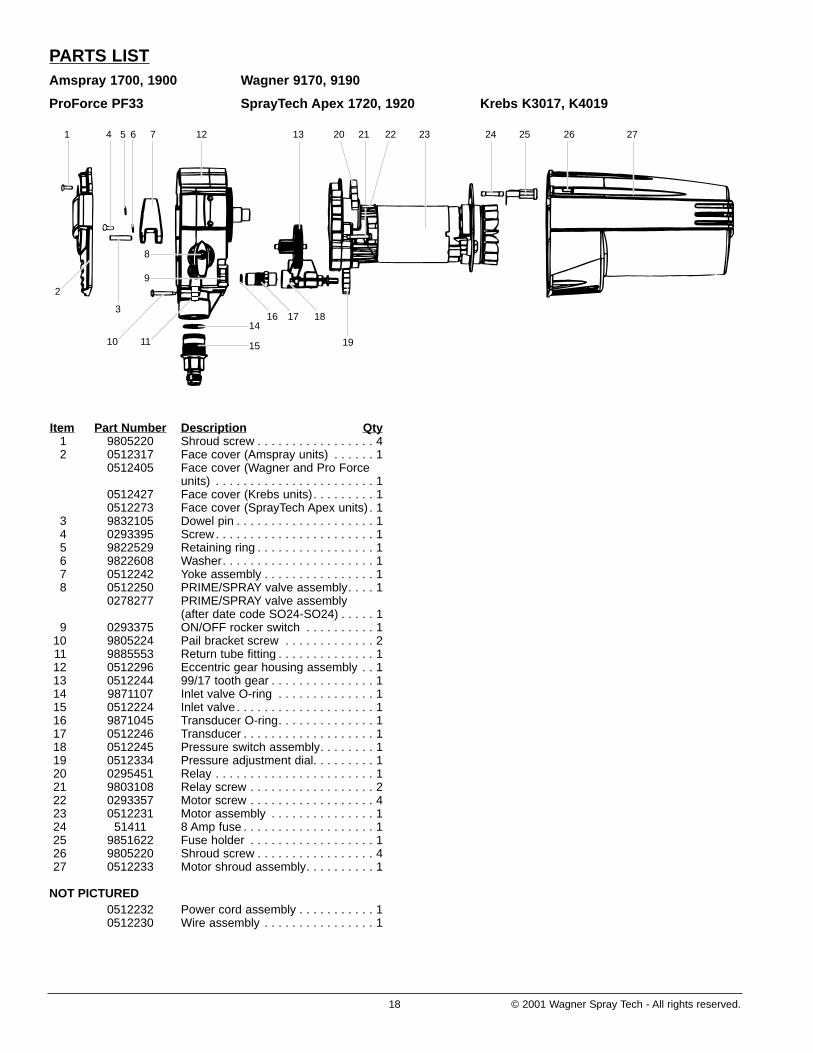
PARTS LISTAmspray 1700, 1900 Wagner 9170, 9190
ProForce PF33 SprayTech Apex 1720, 1920 Krebs K3017, K4019
4 5 61 7 12
1416 17 18
1915
13 23 24 25 26 2721 2220
2
3
8
9
10 11
Item Part Number Description Qty1 9805220 Shroud screw . . . . . . . . . . . . . . . . . 42 0512317 Face cover (Amspray units) . . . . . . 1
0512405 Face cover (Wagner and Pro Forceunits) . . . . . . . . . . . . . . . . . . . . . . . 1
0512427 Face cover (Krebs units). . . . . . . . . 10512273 Face cover (SprayTech Apex units) . 1
3 9832105 Dowel pin . . . . . . . . . . . . . . . . . . . . 14 0293395 Screw. . . . . . . . . . . . . . . . . . . . . . . 15 9822529 Retaining ring . . . . . . . . . . . . . . . . . 16 9822608 Washer. . . . . . . . . . . . . . . . . . . . . . 17 0512242 Yoke assembly . . . . . . . . . . . . . . . . 18 0512250 PRIME/SPRAY valve assembly. . . . 1
0278277 PRIME/SPRAY valve assembly(after date code SO24-SO24) . . . . . 1
9 0293375 ON/OFF rocker switch . . . . . . . . . . 110 9805224 Pail bracket screw . . . . . . . . . . . . . 211 9885553 Return tube fitting . . . . . . . . . . . . . . 112 0512296 Eccentric gear housing assembly . . 113 0512244 99/17 tooth gear . . . . . . . . . . . . . . . 114 9871107 Inlet valve O-ring . . . . . . . . . . . . . . 115 0512224 Inlet valve . . . . . . . . . . . . . . . . . . . . 116 9871045 Transducer O-ring. . . . . . . . . . . . . . 117 0512246 Transducer . . . . . . . . . . . . . . . . . . . 118 0512245 Pressure switch assembly. . . . . . . . 119 0512334 Pressure adjustment dial. . . . . . . . . 120 0295451 Relay . . . . . . . . . . . . . . . . . . . . . . . 121 9803108 Relay screw . . . . . . . . . . . . . . . . . . 222 0293357 Motor screw . . . . . . . . . . . . . . . . . . 423 0512231 Motor assembly . . . . . . . . . . . . . . . 124 51411 8 Amp fuse . . . . . . . . . . . . . . . . . . . 125 9851622 Fuse holder . . . . . . . . . . . . . . . . . . 126 9805220 Shroud screw . . . . . . . . . . . . . . . . . 427 0512233 Motor shroud assembly. . . . . . . . . . 1
NOT PICTURED0512232 Power cord assembly . . . . . . . . . . . 10512230 Wire assembly . . . . . . . . . . . . . . . . 1
© 2001 Wagner Spray Tech - All rights reserved. 19
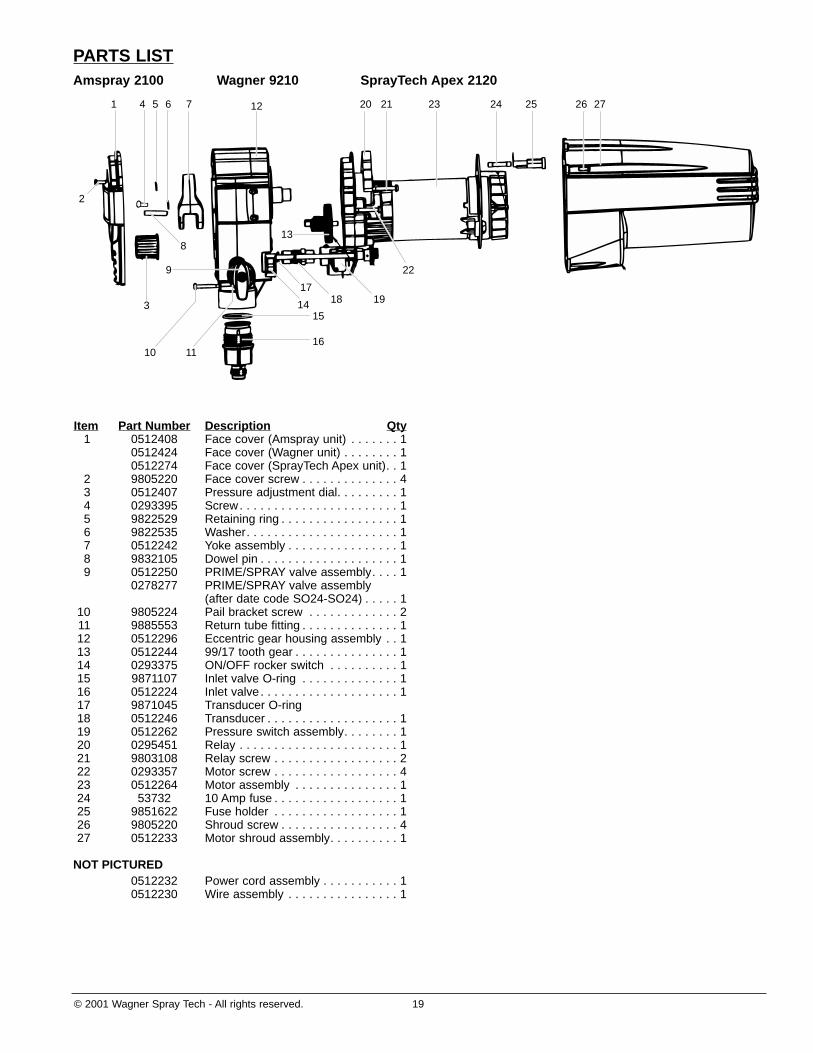
PARTS LISTAmspray 2100 Wagner 9210 SprayTech Apex 2120
2
4
3
10 11
9
5 61 7 12
13
20 21 23 24 25 2726
8
14 1817
19
22
15
16
Item Part Number Description Qty1 0512408 Face cover (Amspray unit) . . . . . . . 1
0512424 Face cover (Wagner unit) . . . . . . . . 10512274 Face cover (SprayTech Apex unit). . 1
2 9805220 Face cover screw . . . . . . . . . . . . . . 43 0512407 Pressure adjustment dial. . . . . . . . . 14 0293395 Screw. . . . . . . . . . . . . . . . . . . . . . . 15 9822529 Retaining ring . . . . . . . . . . . . . . . . . 16 9822535 Washer. . . . . . . . . . . . . . . . . . . . . . 17 0512242 Yoke assembly . . . . . . . . . . . . . . . . 18 9832105 Dowel pin . . . . . . . . . . . . . . . . . . . . 19 0512250 PRIME/SPRAY valve assembly. . . . 1
0278277 PRIME/SPRAY valve assembly(after date code SO24-SO24) . . . . . 1
10 9805224 Pail bracket screw . . . . . . . . . . . . . 211 9885553 Return tube fitting . . . . . . . . . . . . . . 112 0512296 Eccentric gear housing assembly . . 113 0512244 99/17 tooth gear . . . . . . . . . . . . . . . 114 0293375 ON/OFF rocker switch . . . . . . . . . . 115 9871107 Inlet valve O-ring . . . . . . . . . . . . . . 116 0512224 Inlet valve . . . . . . . . . . . . . . . . . . . . 117 9871045 Transducer O-ring18 0512246 Transducer . . . . . . . . . . . . . . . . . . . 119 0512262 Pressure switch assembly. . . . . . . . 120 0295451 Relay . . . . . . . . . . . . . . . . . . . . . . . 121 9803108 Relay screw . . . . . . . . . . . . . . . . . . 222 0293357 Motor screw . . . . . . . . . . . . . . . . . . 423 0512264 Motor assembly . . . . . . . . . . . . . . . 124 53732 10 Amp fuse . . . . . . . . . . . . . . . . . . 125 9851622 Fuse holder . . . . . . . . . . . . . . . . . . 126 9805220 Shroud screw . . . . . . . . . . . . . . . . . 427 0512233 Motor shroud assembly. . . . . . . . . . 1
NOT PICTURED0512232 Power cord assembly . . . . . . . . . . . 10512230 Wire assembly . . . . . . . . . . . . . . . . 1
20 © 2001 Wagner Spray Tech - All rights reserved.
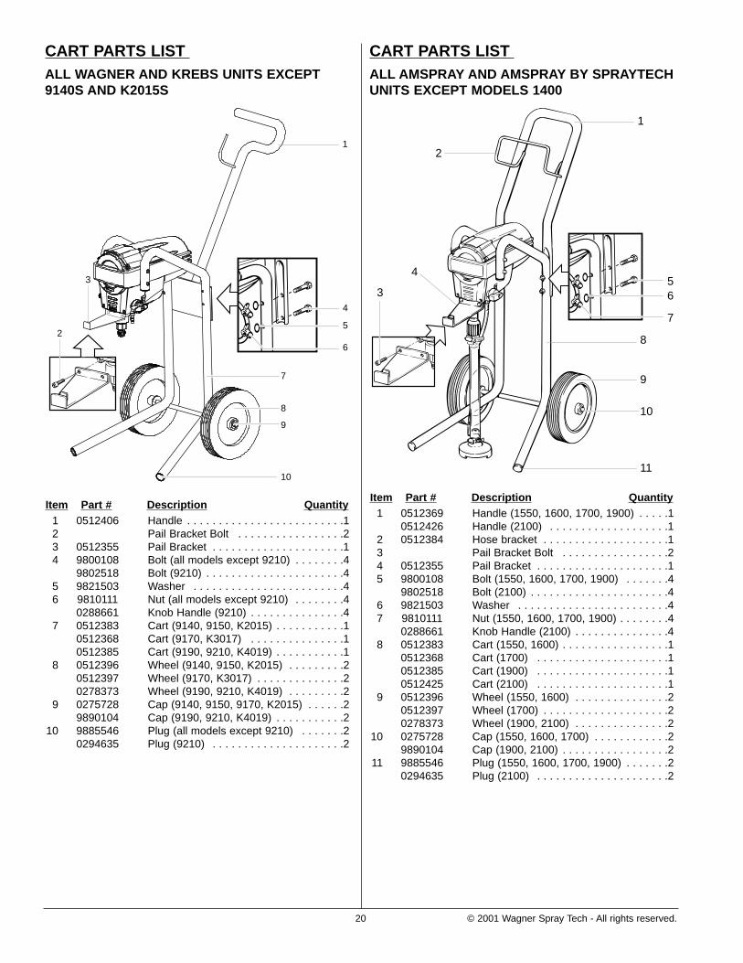
CART PARTS LIST ALL AMSPRAY AND AMSPRAY BY SPRAYTECHUNITS EXCEPT MODELS 1400
Item Part # Description Quantity1 0512369 Handle (1550, 1600, 1700, 1900) . . . . .1
0512426 Handle (2100) . . . . . . . . . . . . . . . . . . .12 0512384 Hose bracket . . . . . . . . . . . . . . . . . . . .13 Pail Bracket Bolt . . . . . . . . . . . . . . . . .24 0512355 Pail Bracket . . . . . . . . . . . . . . . . . . . . .15 9800108 Bolt (1550, 1600, 1700, 1900) . . . . . . .4
9802518 Bolt (2100) . . . . . . . . . . . . . . . . . . . . . .46 9821503 Washer . . . . . . . . . . . . . . . . . . . . . . . .47 9810111 Nut (1550, 1600, 1700, 1900) . . . . . . . .4
0288661 Knob Handle (2100) . . . . . . . . . . . . . . .48 0512383 Cart (1550, 1600) . . . . . . . . . . . . . . . . .1
0512368 Cart (1700) . . . . . . . . . . . . . . . . . . . . .10512385 Cart (1900) . . . . . . . . . . . . . . . . . . . . .10512425 Cart (2100) . . . . . . . . . . . . . . . . . . . . .1
9 0512396 Wheel (1550, 1600) . . . . . . . . . . . . . . .20512397 Wheel (1700) . . . . . . . . . . . . . . . . . . . .20278373 Wheel (1900, 2100) . . . . . . . . . . . . . . .2
10 0275728 Cap (1550, 1600, 1700) . . . . . . . . . . . .29890104 Cap (1900, 2100) . . . . . . . . . . . . . . . . .2
11 9885546 Plug (1550, 1600, 1700, 1900) . . . . . . .20294635 Plug (2100) . . . . . . . . . . . . . . . . . . . . .2
1
10
11
9
8
56
7
2
3
4
CART PARTS LIST ALL WAGNER AND KREBS UNITS EXCEPT9140S AND K2015S
Item Part # Description Quantity1 0512406 Handle . . . . . . . . . . . . . . . . . . . . . . . . .12 Pail Bracket Bolt . . . . . . . . . . . . . . . . .23 0512355 Pail Bracket . . . . . . . . . . . . . . . . . . . . .14 9800108 Bolt (all models except 9210) . . . . . . . .4
9802518 Bolt (9210) . . . . . . . . . . . . . . . . . . . . . .45 9821503 Washer . . . . . . . . . . . . . . . . . . . . . . . .46 9810111 Nut (all models except 9210) . . . . . . . .4
0288661 Knob Handle (9210) . . . . . . . . . . . . . . .47 0512383 Cart (9140, 9150, K2015) . . . . . . . . . . .1
0512368 Cart (9170, K3017) . . . . . . . . . . . . . . .10512385 Cart (9190, 9210, K4019) . . . . . . . . . . .1
8 0512396 Wheel (9140, 9150, K2015) . . . . . . . . .20512397 Wheel (9170, K3017) . . . . . . . . . . . . . .20278373 Wheel (9190, 9210, K4019) . . . . . . . . .2
9 0275728 Cap (9140, 9150, 9170, K2015) . . . . . .29890104 Cap (9190, 9210, K4019) . . . . . . . . . . .2
10 9885546 Plug (all models except 9210) . . . . . . .20294635 Plug (9210) . . . . . . . . . . . . . . . . . . . . .2
2
3
9
10
8
7
1
4
5
6

© 2001 Wagner Spray Tech - All rights reserved. 21
CART PARTS LIST ALL SPRAYTECH APEX AND PRO FORCEUNITS EXCEPT 1420 AND PF23
Item Part # Description Quantity1 0512369 Handle (1620, 1720, PF25, PF33) . . . .1
0512452 Handle (1920) . . . . . . . . . . . . . . . . . . .10512426 Handle (2120) . . . . . . . . . . . . . . . . . . .1
2 0512384 Hose Bracket (1620, 1720, PF25, PF33)10512464 Hose Bracket (1920) . . . . . . . . . . . . . .1
3 Pail Bracket Bolt . . . . . . . . . . . . . . . . .24 0512355 Pail Bracket . . . . . . . . . . . . . . . . . . . . .15 9800108 Bolt (1620, 1720, 1920, PF25, PF33) . .4
9802518 Bolt (2120) . . . . . . . . . . . . . . . . . . . . . .46 9821503 Washer (1620, 1720, 1920, PF25, PF33) . .47 9810111 Nut (1620, 1720, 1920, PF25, PF33) . .4
0288661 Knob Handle (2120) . . . . . . . . . . . . . . .48 0512383 Cart (1620, PF25) . . . . . . . . . . . . . . . .1
0512368 Cart (1720, PF33) . . . . . . . . . . . . . . . .10512385 Cart (1920) . . . . . . . . . . . . . . . . . . . . .10512425 Cart (2120) . . . . . . . . . . . . . . . . . . . . .1
9 0512396 Wheel (1620, PF25) . . . . . . . . . . . . . . .20512397 Wheel (1720, PF33) . . . . . . . . . . . . . . .20278373 Wheel (1920, 2120) . . . . . . . . . . . . . . .2
10 0275728 Cap (1620, 1720, PF25, PF33) . . . . . . .29890104 Cap (1920, 2120) . . . . . . . . . . . . . . . . .2
11 9885546 Plug (1620, 1720, 1920, PF25, PF33) .20294635 Plug (2120) . . . . . . . . . . . . . . . . . . . . .2
10
11
9
8
5
6
7
2
1
4
3
STAND PARTS LISTAMSPRAY 1400 WAGNER 9140S
KREBS K2015S PRO FORCE PF23
SPRAYTECH APEX 1420
AMSPRAY BY SPRAYTECH 1400
Item Part Number Description Qty1 0512336 Stand . . . . . . . . . . . . . . . . . . . . . . . 12 9885546 Plug . . . . . . . . . . . . . . . . . . . . . . . . 23 05045 Outlet hose fitting . . . . . . . . . . . . . . 1
SUCTION SETAMSPRAY 1400 WAGNER 9140S
KREBS K2015S PRO FORCE PF23
SPRAYTECH APEX 1420
AMSPRAY BY SPRAYTECH 1400
Item Part Number Description Qty1 0512215 Suction set assembly . . . . . . . . . . . 12 9885553 Return tube fitting . . . . . . . . . . . . . . 13 0154832 Filter. . . . . . . . . . . . . . . . . . . . . . . . 1
1
2
3
1
2
3
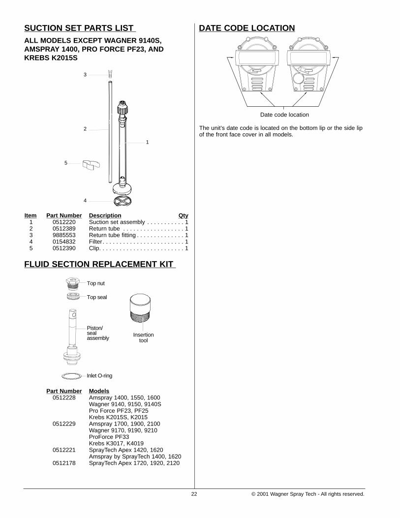
SUCTION SET PARTS LIST ALL MODELS EXCEPT WAGNER 9140S,AMSPRAY 1400, PRO FORCE PF23, ANDKREBS K2015S
Item Part Number Description Qty1 0512220 Suction set assembly . . . . . . . . . . . 12 0512389 Return tube . . . . . . . . . . . . . . . . . . 13 9885553 Return tube fitting . . . . . . . . . . . . . . 14 0154832 Filter. . . . . . . . . . . . . . . . . . . . . . . . 15 0512390 Clip. . . . . . . . . . . . . . . . . . . . . . . . . 1
FLUID SECTION REPLACEMENT KIT
Part Number Models0512228 Amspray 1400, 1550, 1600
Wagner 9140, 9150, 9140SPro Force PF23, PF25Krebs K2015S, K2015
0512229 Amspray 1700, 1900, 2100Wagner 9170, 9190, 9210ProForce PF33Krebs K3017, K4019
0512221 SprayTech Apex 1420, 1620Amspray by SprayTech 1400, 1620
0512178 SprayTech Apex 1720, 1920, 2120
Top seal
Top nut
Piston/sealassembly
Inlet O-ring
Insertiontool
1
2
3
4
5
22 © 2001 Wagner Spray Tech - All rights reserved.
DATE CODE LOCATION
The unit’s date code is located on the bottom lip or the side lipof the front face cover in all models.
Date code location

© 2001 Wagner Spray Tech - All rights reserved. 23
NOTES:
24 © 2001 Wagner Spray Tech - All rights reserved.
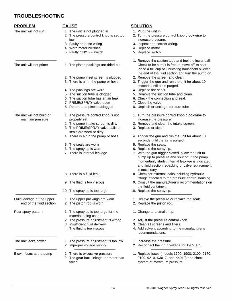
PROBLEMThe unit will not run
The unit will not prime
The unit will not build ormaintain pressure
Fluid leakage at the upperend of the fluid section
Poor spray pattern
The unit lacks power
Blown fuses at the pump
TROUBLESHOOTING
CAUSE1. The unit is not plugged in2. The pressure control knob is set too
low3. Faulty or loose wiring4. Worn motor brushes5. Faulty ON/OFF switch
1. The piston packings are dried out
2. The pump inset screen is plugged3. There is air in the pump or hose
4. The packings are worn5. The suction tube is clogged6. The suction tube has an air leak7. PRIME/SPRAY valve open8. Return tube pinched/clogged
1. The pressure control knob is notproperly set
2. The pump intake screen is dirty3. The PRIME/SPRAY valve balls or
seals are worn or dirty4. There is air in the pump or hose
5. The seals are worn6. The spray tip is worn7. There is internal leakage
8. There is a fluid leak
9. The fluid is too viscous
10. The spray tip is too large
1. The upper packings are worn2. The piston rod is worn
1. The spray tip is too large for thematerial being used
2. The pressure adjustment is wrong3. Insufficient fluid delivery4. The fluid is too viscous
1. The pressure adjustment is too low2. Improper voltage supply
1. There is excessive pressure2. The gear box, linkage, or motor has
failed
SOLUTION1. Plug the unit in.2. Turn the pressure control knob clockwise to
increase pressure.3. Inspect and correct wiring.4. Replace motor.5. Replace switch.
1. Remove the suction tube and feel the lower ball.Check to be sure it is free to move off its seat.Place a full cup of lubricating household oil overthe end of the fluid section and turn the pump on.
2. Remove the screen and clean.3. Trigger the gun and run the unit for about 10
seconds until air is purged.4. Replace the seals.5. Remove the suction tube and clean.6. Check the connection and seal.7. Close the valve8. Unpinch or unclog the return tube
1. Turn the pressure control knob clockwise toincrease the pressure.
2. Remove and clean the intake screen.3. Replace or clean.
4. Trigger the gun and run the unit for about 10seconds until the air is purged.
5. Replace the seals.6. Replace the spray tip.7. With the gun trigger closed, allow the unit to
pump up to pressure and shut off. If the pumpmomentarily starts, internal leakage is indicatedand fluid section repacking or valve replacementis necessary.
8. Check for external leaks including hydraulicfittings attached to the pressure control housing.
9. Consult the manufacturer’s recommendations onthe fluid container.
10. Replace the spray tip.
1. Relieve the pressure or replace the seals.2. Replace the piston rod.
1. Change to a smaller tip.
2. Adjust the pressure control knob.3. Clean all screens and filters.4. Add solvent according to the manufacturer’s
recommendations.
1. Increase the pressure.2. Reconnect the input voltage for 120V AC.
1. Replace fuses (models 1700, 1900, 2100, 9170,9190, 9210, K3017, and K4019) and checksystem at maximum pressure.