SERVICE BULLETIN No BE-059/SZD-50-3/2007...
16
ALLSTAR PZL GLIDER Sp. z o.o. ul. Cieszyńska 325 43-300 Bielsko-Biala phone: +48 (0)33 8125021, fax: +48 (0)33 8123739 e-mail: [email protected] Approval No: EASA Nr AP 108 SERVICE BULLETIN No BE-059/SZD-50-3/2007 „PUCHACZ” DESIGNATION-TYPE/MODEL: SERIA/NUMBER: CONCERNS: COMPLIANCE: SZD-50-3 „Puchacz” All SZD-50-3 “PUCHACZ” gliders up to Serial No B-2207 and serial numbers 503199327, 503A04001, 503A05002, 503A05003. Inspection of the intermediate lever bolt in airbrake control system in the wing. On receiving this Bulletin
Transcript of SERVICE BULLETIN No BE-059/SZD-50-3/2007...

ALLSTAR PZL GLIDER Sp. z o.o. ul. Cieszyńska 325
43-300 Bielsko-Biała phone: +48 (0)33 8125021, fax: +48 (0)33 8123739
e-mail: [email protected] Approval No: EASA Nr AP 108
SERVICE BULLETIN No BE-059/SZD-50-3/2007 „PUCHACZ”
DESIGNATION-TYPE/MODEL: SERIA/NUMBER: CONCERNS: COMPLIANCE:
SZD-50-3 „Puchacz” All SZD-50-3 “PUCHACZ” gliders up to Serial No B-2207 and serial numbers 503199327, 503A04001, 503A05002, 503A05003. Inspection of the intermediate lever bolt in airbrake control system in the wing. On receiving this Bulletin

Issued Revised Page No. Rev. DAY MONTH YEAR DAY MONTH YEAR
1 of 3 A 16 09 2013
ALLSTAR PZL GLIDER Sp. z o. o.
ul. Cieszynska 325, 43-300 Bielsko-Biala, Poland
tel.: +48 33 812 50 26 fax: +48 33 812 3739
[email protected] www.szd.com.pl
SERVICE BULLETIN Allstar PZL Glider considers compliance mandatory
BE-062/SZD-50-3/2013 „PUCHACZ”
DATE: September 16, 2013
SUBJECT: Inspection of torque tube in air-brake control system MODELS AFFECTED: All S/N of SZD-50-3 „Puchacz” TIME OF COMPLIANCE: After receiving the SB
NOTE Incomplete review of all the information in this document can cause errors. Please read the entire SB to make sure you
have a complete understanding of the requirements.
1. BASEGROUND OF THE SB:
The mandatory bulletin BE-052/SZD-50-3/2003 „PUCHACZ”, issued in 2003, did not enclose the information about repetative inspections of torque tube air-brake control system in the fuselage, as well as did not cover the information about processing method after exchanging of infected tube with the new one, equipped with reinforced corner. This SB replaces the BE-052/SZD-50-3/2003 „PUCHACZ” and – additionally – specifies the above information.
Up to 2003, during the flights, while operating the airbrakes, a few incidents of the torque-tube break-off from the lever located in fuselage, had been experienced. The damages occured at the welded joint between the tube and the lever, which did not allow to retract the airbrake.
Possible reason could be a fatigue in the area of frequent occurrence of striking load, exceeding recurrently the established value or/and corrosion detected inside the area of opened tube.
2. COMPLIANCE WITH SB REQUIREMENTS (a) Conditions of inspection:
1. for the gliders still equipped with the old version of torque tube, with or without reinforced corner, do as follows (see Sketch 1): • annually or during „100-hrs” inspection, in case of whichever occurrs first, inspect the welded joint of
airbrake torque tube, acc. to the description specified in item 2(b) of this SB;
2. for the gliders with the new type of torque tube with reinforced corners (see Sketch 2), i.e. the gliders from S/N 503.A.03.001 and up as well as others with the new type torque tube (see Sketch 2) do as follows: • annually or during „100-hrs” inspection, whichever occurrs first, check visually (disasembling of the tube
from the fuselage is not necessary) the welded joint of the torque tube. Inspection of the areas partially obscured by the reinforcing plates is not required.
• during „1000-hrs” inspection check the welded joint of torque tube as described in 2(b) of this SB.

ALLSTAR PZL GLIDER Sp. z o.o.
SERVICE BULLETIN BE-062/SZD-50-3/2013 „PUCHACZ”
Issued Revised Page No. Rev. DAY MONTH YEAR DAY MONTH YEAR
2 of 3 A 16 09 2013
(b) Inspection procedure:
1. Dissassemble the glider.
2. Remove the torque tube of airbrake control system (Fig. 9, item 8 – TSM, issue III/Sept. 1980 or Fig. 8/2, item 8 – TSM, issue I/JAR-22/Nov. 1994).
To do so, proceed as follows: • remove the rear seat panel; • remove the side and rear wall of baggage compartment. The side wall is fastened in front with 2 screws to
main frame, and the rear wall with 2 screws to baggage compartment wall; • disconnect the torque tube from airbrake push-rod (Fig. 9, item 9 – TSM, issue III/Sept. 1980 or Fig. 8/2,
item 9 – TSM, issue I/JAR-22/Nov. 1994); • remove the end of torque tube on lever’s side (Fig. 2, item 6 – TSM, issue III/Sept. 1980 or Fig. 1/2, item 6 –
TSM, issue I/JAR-22/Nov. 1994); • take the torque tube out of the fuselage, raising it up and forward.
3. Check the condition of torque tube in the area of welded joint with lever (as well as the additional reinforcing plates) – see the Sketch 1 or Sketch 2, dependently on the existing solution:
• Check with the 3 x min. magnifying glass for paintig cracks and tube’s condition in the area of welded joint (also reinforcing plates), which could be an evidence of joint and/or tube cracking. If found the cracks of paint, remove coating and check the surface of tube. Fluorescent Penetrant Inspection (FPI) inspection may be done as an optional.
• Check the torque tube for permanent distortion of cylindrical tube’s shape.
a)
b)
Sketch 1 – Previous version of airbrake torque tube: a) without reinforcement; b) with a single reinforcement
inspection area
inspection area additional reinforcement

ALLSTAR PZL GLIDER Sp. z o.o.
SERVICE BULLETIN BE-062/SZD-50-3/2013 „PUCHACZ”
Issued Revised Page No. Rev. DAY MONTH YEAR DAY MONTH YEAR
3 of 3 A 16 09 2013
Sketch 2 – New version of reinforced torque tube
4. Check for evidence of corrosion of the inside welded joint area of torque tube. (c) Post-inspection procedure:
1. Cracks, permanent distortion of torque tube as well as corrosion pit on tube’s inner side in the area of welded joint are not acceptable. In case of one of the defects listed above – replace the tube with the new one, purchased from Allstar PZL Glider – item no. 503.64.30.00A. The old tube may be released into service if no one of described defects exists.
2. Slight, uniform corrosive deposit should be removed with fine abrasive sand paper (grid 600 at min). If no corrosive pits are present on the surface, prevent inner area of the tube with anticorrosive agent (for ex. Fluidol) and release the tube into service. However, replacement the tube with the new one could be reccomended.
- END -
additional reinforcement
inspection area
areas partially obscured by reinforcement

Allstar PZL Glider Sp. z o. o.
SERVICE BULLETIN
No BE-059/SZD-50-3/2007 “PUCHACZ”
Page: 2 of : 4
1. SUBJECT OF BULLETIN. 1.1. Mandatory inspection of bolt of airbrake intermediate lever in wings. 1.2. Replacing washer and bolt mentioned above. 2. GROUNDS OF ISSUANCE OF THIS BULLETIN .
During pre-flight check in one of SZD-50-3 glider, it has been found impossible to fully retract/close the air brake on right hand wing, regardless from retracting successfully air brake on left hand wing and the brake lever in a cockpit locked in ‘CLOSED’ position. In glider inspection, unscrewing of the bolt, fastening an intermediate lever in air brake control from its seat has been found, regardless from having this locked with spring-lock washer. Further inspection detected, that bolt of intermediate lever in air brake control in left wing had been loosen too, regardless from securing this by spring-lock washer. Probable reason for bolt loosening are vibrations, excited by the intermediate lever hitting against its bumper, when retracting the air brake.
3. LIST OF FACTORY NO’S COVERED BY BULLETIN.
This Bulletin concerns all gliders of the SZD-50-3 “PUCHACZ” model up to serial no B-2207 and serial numbers 503199327, 503A04001, 503A05002, 503A05003.
4. BOLT INSPECTION.
The bolt’s head, washer and lever’s console are visible through hole of pushrod (6) in a wall of airbrake box. Following actions must be performed:
4.1 Extend airbrakes. 4.1.Illuminate interior of the wing. 4.2.Inspect visually tightening of the bolt. A gap between bolt’s head and washer, or this between
lever console and washer, considered an evidence of bolt loosening and indicating possibility of further unscrewing, is not acceptable. On left hand wing, using a mirror for inspection would be helpful.
5. RESULTS OF INSPECTION. 5.1. If no loosen bolt has been detected, a glider can be operated normally. Inspection in accordance
with point 4 of this Bulletin must be repeated as periodic work during annual/ (100 hours) check. Replacement of spring-lock-, with tab washers as well as replacement of M8x34 bolts with M8x32 bolts, according to point 6 of this Bulletin must be accomplished during the closest main (1000 hour) overhaul (or at earlier repair).
5.2. If a loosen bolt has been detected, glider must be considered non-airworthy, and replacement of
the spring-lock washers with tab washers, as well as M8x34 bolts with M8x32 bolts must be done in both wings, according to point 6 of this Bulletin.

Allstar PZL Glider
Sp. z o. o.
SERVICE BULLETIN
No BE-059/SZD-50-3/2007 “PUCHACZ”
Page: 3 of : 4
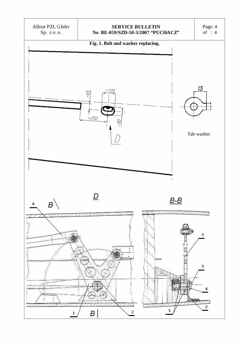
6. REPLACING OF BOLTS AND WASHERS. Replacing of bolts and washers must be performed by certified maintenance organization. 6.1.De-rig the wing. 6.2.Cut a hole in upper skin of the wing, according to Fig. 1. 6.3. Screw out and remove bolt M8x34, remove also spring-lock washer and spacer washers (5). 6.4. Screw in bolt M8x32 (3), with a tab washer (4) as a locking device, inserting also spacer
washers (5) on their place. 6.5.Bend a tab of the tab washer (4) on the lever console (2) as shown in “D“ view. Bend tab
washer on the bolt (3) head, at arbitrary selected position. 6.6.After ensuring that assembling has been performed correctly, and bolt reliably locked by tab
washer bent, repair the hole in wing skin according to Repair Manual of the glider. 7. PARTS NECESSARY FOR REPLACEMENT. 7.1. Tab washers can be purchased from Allstar PZL Glider, or similar can be used, for example
FABORY no. 51540 M8. Washer’s tab is to be cut to 15 mm. 7.2. Bolt M8x32 must be purchased from Allstar PZL Glider. 8. FINAL CONCLUSIONS.
8.1 Replacing of bolts and washers in accordance with point 6 of current bulletin is to be recorded at appropriate position in a Glider Log Book.
8.2. For gliders veryfied during inspection as in point 5.1, introduce following revisions in Technical Service Manual (TSM):
8.2.1. In TSM issue III, september 1980 and issue IV, may 981 in point 3.4. in column ‘Maintenance work’ in rows ‘After every 100 flying hours’ and ‘On the end of flying season or before the prolonged hangaring’ add ‘Bulletin BE-059/SZD-50-3/2007’.
8.2.2. In TSM issue I/JAR-22, may 1994 in point 15.7 in column ‘Maintenance work’ in row ‘After every 100 flying hours’ add ‘Bulletin BE-059/SZD-50-3/2007’.
8.2.3. Introduced revisions must be recorded in Record of Revisions in TSM.. 8.2.4. After replacing bolts and washers according to point 6 of current bullettin, cancel revisions
recorded according to points 8.2.1. or 8.2.2. Cancellation must be recorded in Record of Revisions in TSM.
8.3. If loosen bolt is detected, Operator of the glider is requested to notify Allstar PZL Glider on this fact, specifying: Serial Number of glider, total flight time, number of landings, and Operator/Owner data.
8.4. The operator is introducing this Bulletin at his own cost. 9. DESCRIPTION OF FIG. 1. 1- intermediate lever in airbrake control system 2- lever’s console 3- M8x32 bolt 4- tab washer 5- 8,5x1 washer 6- pushrod
Allstar PZL Glider
Sp. z o. o.
SERVICE BULLETIN
No BE-059/SZD-50-3/2007 “PUCHACZ”
Page: 4 of : 4
Fig. 1. Bolt and washer replacing.
1 2 2
1
5
4
3
6
Tab washer

ALLSTAR PZL GLIDER Sp. z o.o. ul. Cieszyńska 325
43-300 Bielsko-Biała phone: +48 (0)33 8125021, fax: +48 (0)33 8123739
e-mail: [email protected] Approval No: GICA-CAIB D-10/JA/2001, EASA No AP 108
ACCEPTED BY President of Allstar PZL Glider Sp. z o.o.
Andrzej Papiorek, MSc. Eng.
APPROVED BY
EASA
EASA AD 2006 - 0243 - E
MANDATORY BULLETIN No BE-058/SZD-50-3/2006 „PUCHACZ”
DESIGNATION-TYPE/MODEL: SERIA/NUMBER: CONCERNS: COMPLIANCE:
SZD-50-3 „Puchacz” All gliders of SZD-50-3 “PUCHACZ” model Inspection of the rudder bottom hinge and revision to the Technical Service Manual On receiving this Bulletin
ELABORATED BY:
Responsible for Type Design Marian Kroczek, MSc. Eng
(signature, date)
AGREED WITH
Civil Aviation Office Southern Division, Krakow
[---]
(signature, date)
Translated by
Tadeusz Zboś

Allstar PZL Glider Sp. z o.o.
MANDATORY BULLETIN No BE-058/SZD-50-3/2006 "PUCHACZ"
Page: 2 of: 4
1. SUBJECT OF THIS BULLETIN 1.1. Herewith, an inspection of the nut securing the rudder bottom hinge is introduced.
1.2. The revision to the Technical Service Manual is introduced.
2. GROUNDS FOR ISSUANCE OF THIS BULLETIN On one PUCHACZ glider, in the take-off phase, the rudder slipped out of its hinges and separated from the glider. The cause might be unscrewing of the fastening the bottom hinge castellated nut, not secured with the cotter pin, or unscrewing of the employed self-locking nut. Comparison between the design documentation and the Technical Service Manual revealed that no revision concerning the exchange of the self-locking nut to the secured with cotter pin castellated nut has been done to the Manual The castellated nut is used in production from the Fact. No B-967. Also, the Bulletin No BE-06/50-3/81 SZD-50-3 “Puchacz” introducing the exchange of the self-locking nut with the castellated one on operated already Fact. Nos up to B-966 has been issued. The non modified entry in the Technical Service Manual may cause that in an inspection and disassembly of the rudder, instead of a castellated nut with cotter pin, a self-locking nut may be used to secure the rudder bottom hinge.
3. LIST OF FACTORY NOS COVERED WITH THIS BULLETIN This Bulletin concerns all gliders of the SZD-50-3 “PUCHACZ” model.
4. DESCRIPTION OF MODIFICATION 4.1 , Check by visual inspection the nut securing the lower hinge – see Fig. A. This one must be
of the hexagon, castellated model (1) with the visible cotter pin (2).
4.2 In case of nut different from this one specified under item 4.1, proceed as follows: − undo the nut, − disassemble the rudder from hinges, − clean the opening for a cotter pin, one located in the bottom, threaded portion of the
rudder pin, − grease the hinge bolts 14 and 15, as well as the pins 16 – Technical Service Manual, Fig.
8 or 7/2 (see item 4.3), − re-assemble the rudder on a vertical fin, − install the 6 mm diameter, 1.5 mm thick steel washer − screw on the M6 aircraft thin, castellated nut − install the 1.6 mm diameter cotter pin

Allstar PZL Glider Sp. z o.o.
MANDATORY BULLETIN No BE-058/SZD-50-3/2004 "PUCHACZ"
Page: 3 of: 4
4.3 Make the revisions to the glider Technical Service Manual: 4.3.1. In the issue III, September 1980 and in the issue IV, May 1981, for the gliders equipped
with the a.m. Manuals − in item 2.1 “Disassembling and assembling of rudder” replace the first portion of the
sentence “ For disassembling remove the self-locking nut 2 ……” with “For disassembling remove the cotter pin 26, unscrew the castellated nut 2 …..”,
− in the legend to Fig. 8 – Rudder control system and assembly � in item 2 cancel the word “self-locking” and insert “castellated” � add item “25 – washer” � add item “26 – cotter pin”
− in the detail “A”, Fig. 8, side to the reference 2 add 25 and 26 (see Fig. B of the Bulletin)
4.3.2. In the issue I/JAR-22, November 1994, for the gliders equipped with this Manual, replace pages 0.1; 0.3; 2.16 and 2.17 with pages 0.1a; 0.3a; 2.16a and 2.17a respectively.
5. PARTS NECESSARY FOR THE MODIFICATION In necessity of a nut exchange – the M6 aircraft thin, castellated nut and the 1.6 mm diameter cotter pin can be purchased at Allstar PZL Glider, or substituted with the analogous aircraft model.
6. LIST OF ENCLOSURES Pages 0.1a; 0.3a; 2.16a; 2.17a of the Technical Service Manual issue I/JAR-22, November 1994.
7. FINAL CONCLUSIONS 7.1 Entry on the compliance with this Bulletin is to be done at appropriate position in a Glider
Log Book.
7.2 In the Technical Service Manual issue III, September 1980 and issue IV, May 1981, the revisions introduced with this Bulletin should be indicated on the concerned page with the vertical line on the left hand side of the revised text, and with subsequent revision No – 54, these must be recorded also in the “RECORD OF REVISIONS” of the concerned Manual.
7.3 The operator is introducing this Bulletin at his own cost.

Allstar PZL Glider Sp. z o.o.
MANDATORY BULLETIN No BE-058/SZD-50-3/2004 "PUCHACZ"
Page: 4 of: 4
- THE END -

ALLSTAR PZL GLIDER Sp. z o.o. ul. Cieszyńska 325
43-300 Bielsko-Biała phone: +48 (0)33 8125021, fax: +48 (0)33 8123739
e-mail: [email protected] GICA-CAIB Approval No P-023
ACCEPTED BY President of Allstar PZL Glider Sp. z o.o.
on:
[---], . (signature, date)
Andrzej Papiorek, MSc. Eng.
APPROVED BY EASA
AD No: 2006-0317
16 October 2006
MANDATORY BULLETIN No BE-057/SZD-50-3/2006 „PUCHACZ”
DESIGNATION-TYPE/MODEL: SZD-50-3 “PUCHACZ”
SERIA / NUMBER: All gliders of SZD-50-3 “PUCHACZ” model
CONCERNS: Introduction of an extra pull rod segment in the rudder control system
COMPLIANCE: On receiving this Bulletin
ELABORATED BY: AGREED WITH
Responsible for Type Design Civil Aviation Office Southern Division, Krakow
Marian Kroczek, MSc. Eng.
[---], (signature, date)
[---], (signature, date)
Translated by
............... Tadeusz Zboś

Allstar PZL Glider Sp. z o.o.
MANDATORY BULLETIN No BE-057/SZD-50-3/2006 "PUCHACZ"
Page: 2 of: 3
1. SUBSTANCE OF THIS BULLETIN
Herewith, an extra segment of pull rod ((1) – Fig (1), of approx 140mm length “l”, is being introduced between the rear pedals (2) and turnbuckle (3) of pull rod connected to a rudder.
2. GROUNDS FOR ISSUANCE OF THIS BULLETIN This modification is aimed at elimination of the lateral load component applied at turnbuckle terminal by {pilot} foot. In several instances this has brought to fatigue failure and break of the terminal at the site of transition into eyelet.
3. LIST OF FACTORY NOS COVERED WITH THIS BULLETIN This Bulletin concerns all gliders of SZD-50-3 “PUCHACZ” model.
4. DESCRIPTION OF MODIFICATION 4.1 , On the gliders, where the eyelet terminal of the turnbuckle is connected directly to the
pedals, the terminals are to be disconnected from the left-, and right pedal and scrapped. The eyelet type terminals are to be replaced with fork type with the same thread (right/left hand).
4.2 Between the pedals (2) and turnbuckle (3), install a short pull rod (1) of aircraft type steel cable with 3 mm diameter core and approx 140mm length “l”. The length is to be adjusted so that the shield of the wheel brake pull rod (4), on a left side board, remains between the turnbuckle lateral screws (5) over the whole travel of turnbuckle (fore-aft).
4.3 Shorten the pull rods (6) connecting a rudder with rudder by a value obtained by adding the length of extra pull rod with a difference between the eyelet- and fork terminal lengths.
4.4 The M4 nuts, securing the connection between the pull rod and pedal are to be of a castellated, thin type with 1 mm diameter cotter pin.
5. PARTS NECESSARY FOR THE MODIFICATION
The parts necessary for modification are available at Allstar PZL Glider, or substitutive aircraft parts may be used – capable to withstand a load of 6100N at minimum.
6. FINAL CONCLUSIONS 6.1 Entry on the compliance with this Bulletin is to be done at appropriate position in a Glider
Log Book. 6.2 For gliders, on which the extra pull rod segment described under item 4.2 has already been
introduced, this fact is to be recorded in a Glider Log Book. Item 4.4 of this Bulletin applies.

Allstar PZL Glider Sp. z o.o.
MANDATORY BULLETIN No BE-057/SZD-50-3/2004 "PUCHACZ"
Page: 3 of: 3
6.3 The revisions to Technical Service Manual, resulting of compliance with this Bulletin, will be
contained in the next bulletin, concerning the revisions resulting of the model service life extension to 12000 flying hours.
6.4 The operator is introducing this Bulletin at his own cost.
- THE END -

BULLETIN No BE-29/50-3/86 "PUCHACZ"
This is the translation of Polish text approved by CACA.
1. GROUNDS FOR AND THE WAY OF INTRODUCING THIS BULLETIN
This Bulletin has been issued to introduced the revisions in Technical Service Manual with the Schedule of Maintenance works, issue III, Sept. 1980
The revisions result from:
I. Extension of flight limitation to inverted flight and extended range of aerobatic manoeuvres.
II. Extension of glider life-time to 4000 flying hours.
/Extension of this life-time provided after completing the structure fatigue tests/.
2. LIST OF GLIDERS COVERED WITH THIS BULLETIN
All SZD[??]0-3 "PUCHACZ" gliders up to Fact. No. B-1613 incl. The gliders having Fact. Nos. above B-1617 incl. are equipped with the revised Manuals.
3. DESCRIPTION OF REVISIONS INTRODUCED
3.1. Introduced page 2a instead of 2
3.2. Introduced page 16a instead of 16
3.3. Introduced page 33a instead of 33
3.4. Introduced page 34a instead of 34
3.5. On page 36 the item [??].4.2 has been revised into 3.6.2
3.6. On page 37a the item 3.4.3 has been revised into 3.6.3 and item 3.[??].4 into 3.6[??]
3.7. On Fig. 3 the locking device with lever item 9 has been added [??] the drawing
3.8. On page "Explanation for Fig. 13" has been added:
[??] - Lever of locking device
4. LIST OF ENCLOSURES TO THIS BULLETIN
Pages: 2[??], 16a, 33a, [??]4a, 36, 37a, Fig. 13 and "Explanation of Fig. 13" have been enclosed.
5. WAY OF INTRODUCING THIS BULLETIN AND FINAL REMARKS
5.1 This Bulletin is to be introduced by the user himself.

5.2. The page 1[??] and revisions on Fig. 13 and page "Explanation for Fig. 13" are to be introduced by the user as obligatory for these gliders, which are intended for operation with inverted flight and additional aerobatic manoeuvres included, acc. to Flight Manual, issue III, or in case the locking device with lever in fitting tube item [??] /see Fig. 13/ has been installed.
FOR REMAINDER OF SUPPLEMENT PAGES SEE BULLETIN NO. BE-29/50-3/86.