Service Bulletin - Marine Parts Express Recall... · Official Recall Notification U.S. Federal Boat...
10
Service Bulletin Bulletin No. 2008-02 OEM No. 2008-01 Circulate to: Sales Manager Accounting Service Manager Technician Parts Manager THE INFORMATION IN THIS DOCUMENT IS CONFIDENTIAL AND PROTECTED BY COPYRIGHT AND IS THE PROPERTY OF MERCURY MARINE. This document is provided for the sole and exclusive use of the original recipient as prescribed by Mercury Marine and may not be distributed or copied, digitally or otherwise, without the prior written consent of Mercury Marine. 2008-02 JUNE 2008 © 2008 Mercury Marine Page 1 / 9 Official Recall Notification U.S. Federal Boat Safety Act Start In‑Gear Protection ‑ Tiller Handle Kits Models Affected Models Covered Model Year 115 HP FourStroke 2003 75–115 HP FourStroke 2004 75–115 HP FourStroke 2005 through April 1, 2008 Tiller Handle Kit Part Numbers: 816366A32 816366A38 816366A35 (superseded to A46) 816366A46 816366A36 (superseded to A38) 816366A50 816366A37 34103
Transcript of Service Bulletin - Marine Parts Express Recall... · Official Recall Notification U.S. Federal Boat...
Service Bulletin Bulletin No. 2008-02
OEM No. 2008-01
Circulate to: Sales Manager Accounting Service Manager Technician Parts Manager
THE INFORMATION IN THIS DOCUMENT IS CONFIDENTIAL AND PROTECTED BY COPYRIGHT AND IS THE PROPERTY OF MERCURY MARINE.
This document is provided for the sole and exclusive use of the original recipient as prescribed by Mercury Marine and may not be distributed or copied, digitally orotherwise, without the prior written consent of Mercury Marine.
2008-02 JUNE 2008 © 2008 Mercury Marine Page 1 / 9
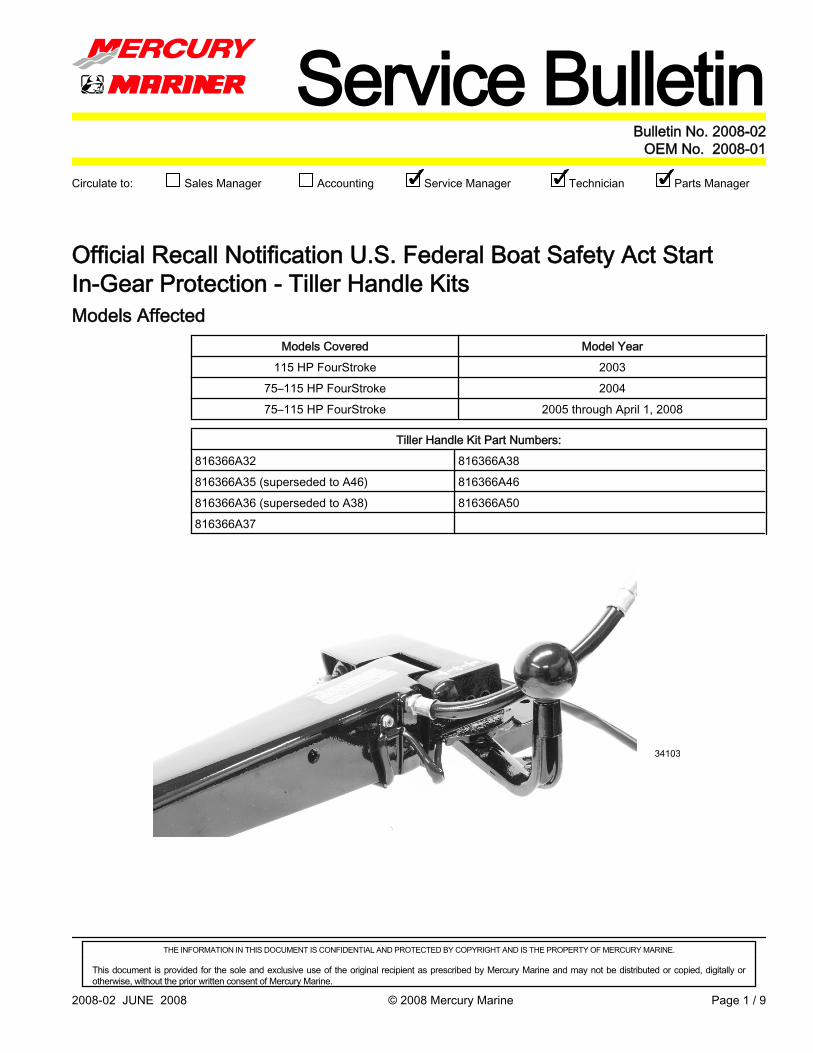
Official Recall Notification U.S. Federal Boat Safety Act StartIn‑Gear Protection ‑ Tiller Handle KitsModels Affected
Models Covered Model Year115 HP FourStroke 2003
75–115 HP FourStroke 200475–115 HP FourStroke 2005 through April 1, 2008
Tiller Handle Kit Part Numbers:816366A32 816366A38816366A35 (superseded to A46) 816366A46816366A36 (superseded to A38) 816366A50816366A37
34103

Official Recall Notification U.S. Federal Boat Safety Act Start In-Gear Protection - Tiller Handle Kits
THE INFORMATION IN THIS DOCUMENT IS CONFIDENTIAL AND PROTECTED BY COPYRIGHT AND IS THE PROPERTY OF MERCURY MARINE.
This document is provided for the sole and exclusive use of the original recipient as prescribed by Mercury Marine and may not be distributed or copied, digitally orotherwise, without the prior written consent of Mercury Marine.
Page 2 / 9 © 2008 Mercury Marine JUNE 2008 2008-02
SituationMercury Marine provides start in‑gear protection on tiller handle kits for the 75–115horsepower engines. Mercury Marine has determined when the shift lever is not positionedpositively into the forward or reverse gear detent or into the neutral detent, the engine maystart in‑gear.
Dealer Parts InventoryDealer/OEM stock.USA customers: Return any of the affected tiller handle kits in your inventory using theMercury Parts and Accessories Non‑Warranty Return Policy. You may use the form on theback of any parts and accessories packing list. Please note on the form that the return ispart of Outboard Service Bulletin 2008‑02 or OEM Service Bulletin 2008‑01. All returnsmust be sent freight prepaid to:Mercury MarineAttn: Return Goods - Outboard Service Bulletin 2008-02/OEM Service Bulletin 2008-01W6250-22A Pioneer RoadFond du Lac, WI 54935Non-USA customers: Return any of the affected tiller handle kits to the appropriatedistribution center for credit. Follow the normal return parts procedure. Please makereference to Outboard Service Bulletin 2008‑02 or OEM Service Bulletin 2008‑01.
InspectionMercury Marine has updated the kits in Mercury stock. Any new kits produced after April1, 2008 will have the updated components. A white dot is located on the underside of thenew shift lever. Kits in the field, or kits previously installed on an engine, may be inspectedfor a white dot on the underside of the shift lever.
ab
34104
a - New style with pointed switch activatorb - Original style with flat at the top of the switch activator
34106
Shift lever with white dot

Official Recall Notification U.S. Federal Boat Safety Act Start In-Gear Protection - Tiller Handle Kits
THE INFORMATION IN THIS DOCUMENT IS CONFIDENTIAL AND PROTECTED BY COPYRIGHT AND IS THE PROPERTY OF MERCURY MARINE.
This document is provided for the sole and exclusive use of the original recipient as prescribed by Mercury Marine and may not be distributed or copied, digitally orotherwise, without the prior written consent of Mercury Marine.
2008-02 JUNE 2008 © 2008 Mercury Marine Page 3 / 9
The neutral switch will also have a white dot by the mounting holes, although it may not bevisible without removal. The part number 8M0033667 will be on the switch harness.
34105
Shift switch with white dot
CorrectionIf no white dot was observed during the inspection process, the update is performed byreplacing the shift lever on the tiller assembly.1. Before performing the update, ensure the engine is in good running condition to ensure
there are no other starting related issues (low battery, poor connections, for example).2. Remove the battery cables, negative cable first.3. Remove the shift lever ball and stud. This can be done by using a strap wrench and a
heat lamp (if necessary) on the stud location in the shift lever. If the stud did not comeoff with the shift ball, then remove the 0.375 x 24 stud from the lever by double nuttingthe stud and using the heat lamp on the lever. Retain the ball and stud.
34107
4. Remove the shift rod from the shift lever and retain the bushing, washer, and cotter pin.
Official Recall Notification U.S. Federal Boat Safety Act Start In-Gear Protection - Tiller Handle Kits
THE INFORMATION IN THIS DOCUMENT IS CONFIDENTIAL AND PROTECTED BY COPYRIGHT AND IS THE PROPERTY OF MERCURY MARINE.
This document is provided for the sole and exclusive use of the original recipient as prescribed by Mercury Marine and may not be distributed or copied, digitally orotherwise, without the prior written consent of Mercury Marine.
Page 4 / 9 © 2008 Mercury Marine JUNE 2008 2008-02
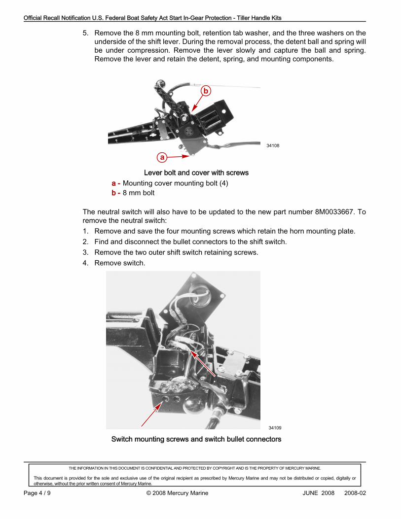
5. Remove the 8 mm mounting bolt, retention tab washer, and the three washers on theunderside of the shift lever. During the removal process, the detent ball and spring willbe under compression. Remove the lever slowly and capture the ball and spring.Remove the lever and retain the detent, spring, and mounting components.
a
b
34108
Lever bolt and cover with screwsa - Mounting cover mounting bolt (4)b - 8 mm bolt
The neutral switch will also have to be updated to the new part number 8M0033667. Toremove the neutral switch:1. Remove and save the four mounting screws which retain the horn mounting plate.2. Find and disconnect the bullet connectors to the shift switch.3. Remove the two outer shift switch retaining screws.4. Remove switch.
34109
Switch mounting screws and switch bullet connectors

Official Recall Notification U.S. Federal Boat Safety Act Start In-Gear Protection - Tiller Handle Kits
THE INFORMATION IN THIS DOCUMENT IS CONFIDENTIAL AND PROTECTED BY COPYRIGHT AND IS THE PROPERTY OF MERCURY MARINE.
This document is provided for the sole and exclusive use of the original recipient as prescribed by Mercury Marine and may not be distributed or copied, digitally orotherwise, without the prior written consent of Mercury Marine.
2008-02 JUNE 2008 © 2008 Mercury Marine Page 5 / 9
Reinstall the components in reverse order using the new shift lever part number8M0033001 and the new shift switch part number 8M0033667. Use Loctite 271Threadlocker on the 8 mm lever mounting bolt threads and tighten to the specified torque.Also use Loctite 271 Threadlocker on the shift ball mounting stud threads, both for the leverand ball ends, and hand‑tighten.
Description Nm lb. in. lb. ft.Bolt 8.5 75
Tube Ref No. Description Where Used Part No.
7 Loctite 271 Threadlocker8 mm lever mounting bolt
threads and shift ball mountingstud threads
92-809819
Shift Link Rod Installation and AdjustmentFOR TILLER KITS 816366A37 AND 816366A50 (L4NA)
1. Position the shift lever into neutral.2. Manually shift the outboard shift link pin into neutral. The propeller will turn freely in
both directions when in neutral.
a
21265
a - Shift link pin

Official Recall Notification U.S. Federal Boat Safety Act Start In-Gear Protection - Tiller Handle Kits
THE INFORMATION IN THIS DOCUMENT IS CONFIDENTIAL AND PROTECTED BY COPYRIGHT AND IS THE PROPERTY OF MERCURY MARINE.
This document is provided for the sole and exclusive use of the original recipient as prescribed by Mercury Marine and may not be distributed or copied, digitally orotherwise, without the prior written consent of Mercury Marine.
Page 6 / 9 © 2008 Mercury Marine JUNE 2008 2008-02
3. Install the shift link rod to the shift handle with a bushing and a washer. Secure the shiftlink rod with a cotter pin. Bend both ends of the cotter pin.
ab
cd
21271
a - Shift link rodb - Nylon bushing
c - Flat washerd - Cotter pin
4. Adjust the length of the shift link rod until it slips over the shift link pin. Secure the shiftlink rod with the jam nut. Install the hair pin retainer.
5. Install the shift link into the retainer. Secure the shift link with the retainer latch.
ab
cd
e f
22673
g
a - Retainer latchb - Shift link retainerc - Shift link rodd - Jam nut
e - Shift link rod endf - Shift link ping - Hair pin retainer
6. Ensure that the shift lever is in neutral. The propeller should turn freely.7. Place the gear shift lever into the forward position. The propeller should ratchet in a
clockwise direction. If the propeller rotates freely, remove the shift link rod from the shiftlink pin and shorten the length of the link rod. Loosen the jam nut and turn the link rodend onto the rod. Repeat step 6.

Official Recall Notification U.S. Federal Boat Safety Act Start In-Gear Protection - Tiller Handle Kits
THE INFORMATION IN THIS DOCUMENT IS CONFIDENTIAL AND PROTECTED BY COPYRIGHT AND IS THE PROPERTY OF MERCURY MARINE.
This document is provided for the sole and exclusive use of the original recipient as prescribed by Mercury Marine and may not be distributed or copied, digitally orotherwise, without the prior written consent of Mercury Marine.
2008-02 JUNE 2008 © 2008 Mercury Marine Page 7 / 9
8. While rotating the propeller, move the shift lever into the reverse position. The propellershould not rotate in either direction. If the propeller rotates freely, remove the shift linkrod from the shift link pin, loosen the jam nut, and lengthen the link rod. Repeat steps6 through 8.
9. Move the shift lever into the neutral position. The propeller must turn freely in bothdirections. If not, the length of the link rod must be adjusted. Repeat steps 6 through9.
10. Tighten the jam nut securely when the shift link rod adjustment is correct.
FOR TILLER KITS 816366A32, 816366A35, 816366A36, 816366A38 AND 816366A461. Position shift lever into neutral.2. Manually shift the outboard shift link pin into neutral. The propeller will turn freely in
both directions when in neutral.3. Install the shift link rod to the shift handle with a bushing and washer. Secure the shift
link rod with a cotter pin. Bend the ends of the cotter pin.4. Install the shift link rod end over the shift link pin. Install the hair pin retainer.
14948
c
a
de
f
g
F W
T
B S
S H
b
75/90 EFI modelsa - Shift leverb - Shift link rod openingc - Shift link rodd - Jam nut
e - Shift link rod endf - Hair pin retainerg - Shift link pin
Official Recall Notification U.S. Federal Boat Safety Act Start In-Gear Protection - Tiller Handle Kits
THE INFORMATION IN THIS DOCUMENT IS CONFIDENTIAL AND PROTECTED BY COPYRIGHT AND IS THE PROPERTY OF MERCURY MARINE.
This document is provided for the sole and exclusive use of the original recipient as prescribed by Mercury Marine and may not be distributed or copied, digitally orotherwise, without the prior written consent of Mercury Marine.
Page 8 / 9 © 2008 Mercury Marine JUNE 2008 2008-02
ad
e
f
gc
14861
F W
T
B S
S H bh
i
j
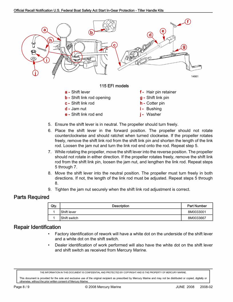
115 EFI modelsa - Shift leverb - Shift link rod openingc - Shift link rodd - Jam nute - Shift link rod end
f - Hair pin retainerg - Shift link pinh - Cotter pini - Bushingj - Washer
5. Ensure the shift lever is in neutral. The propeller should turn freely.6. Place the shift lever in the forward position. The propeller should not rotate
counterclockwise and should ratchet when turned clockwise. If the propeller rotatesfreely, remove the shift link rod from the shift link pin and shorten the length of the linkrod. Loosen the jam nut and turn the link rod end onto the rod. Repeat step 5.
7. While rotating the propeller, move the shift lever into the reverse position. The propellershould not rotate in either direction. If the propeller rotates freely, remove the shift linkrod from the shift link pin, loosen the jam nut, and lengthen the link rod. Repeat steps5 through 7.
8. Move the shift lever into the neutral position. The propeller must turn freely in bothdirections. If not, the length of the link rod must be adjusted. Repeat steps 5 through8.
9. Tighten the jam nut securely when the shift link rod adjustment is correct.
Parts RequiredQty. Description Part Number
1 Shift lever 8M00330011 Shift switch 8M0033667
Repair Identification• Factory identification of rework will have a white dot on the underside of the shift lever
and a white dot on the shift switch.• Dealer identification of work performed will also have the white dot on the shift lever
and shift switch as received from Mercury Marine.

Official Recall Notification U.S. Federal Boat Safety Act Start In-Gear Protection - Tiller Handle Kits
THE INFORMATION IN THIS DOCUMENT IS CONFIDENTIAL AND PROTECTED BY COPYRIGHT AND IS THE PROPERTY OF MERCURY MARINE.
This document is provided for the sole and exclusive use of the original recipient as prescribed by Mercury Marine and may not be distributed or copied, digitally orotherwise, without the prior written consent of Mercury Marine.
2008-02 JUNE 2008 © 2008 Mercury Marine Page 9 / 9
Owner NotificationA letter will be sent to every Mercury Marine customer that purchased an affected kit. Theletter will advise the customer to return the kit to their selling dealer or any MercuryOutboard authorized dealer for the repair. As a selling or servicing dealer, you should alsocontact your customers to make them aware of this recall and to schedule an appointmentfor this repair. A copy of the customer letter is included with this service bulletin for yourreference.
WarrantyMercury Marine will credit the dealer for the cost of parts and labor.Complete a Parts and Accessories warranty claim listing:• Outboard engine serial number• Reference Outboard Service Bulletin 2008‑02 or OEM Service Bulletin 2008‑01 in the
text• Qty. 1, shift lever part number 8M0033001• Qty. 1, shift switch part number 8M0033667• Part code: 243• Failure code: 40• Warranty flat rate code: SB05 for inspection only• Labor: 0.5 houror• Warranty flat rate code: SB12 for inspection, parts replacement, system setup, and
system check• Labor: 1.2 hours
US AND CANADAComplete and process the claim via MercNET or return a warranty claim form.
INTERNATIONALFollow instructions issued by the Marine Power International office or by an authorizedMarine Power Distributor.
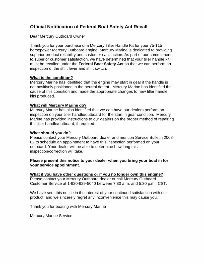
Official Notification of Federal Boat Safety Act Recall Dear Mercury Outboard Owner Thank you for your purchase of a Mercury Tiller Handle Kit for your 75-115 horsepower Mercury Outboard engine. Mercury Marine is dedicated to providing superior product reliability and customer satisfaction. As part of our commitment to superior customer satisfaction, we have determined that your tiller handle kit must be recalled under the Federal Boat Safety Act so that we can perform an inspection of the shift lever and shift switch. What is the condition? Mercury Marine has identified that the engine may start in gear if the handle is not positively positioned in the neutral detent. Mercury Marine has identified the cause of this condition and made the appropriate changes to new tiller handle kits produced. What will Mercury Marine do? Mercury Marine has also identified that we can have our dealers perform an inspection on your tiller handle/outboard for the start in gear condition. Mercury Marine has provided instructions to our dealers on the proper method of repairing the tiller handle/outboard, if required. What should you do? Please contact your Mercury Outboard dealer and mention Service Bulletin 2008-02 to schedule an appointment to have this inspection performed on your outboard. Your dealer will be able to determine how long this inspection/correction will take. Please present this notice to your dealer when you bring your boat in for your service appointment. What if you have other questions or if you no longer own this engine? Please contact your Mercury Outboard dealer or call Mercury Outboard Customer Service at 1-920-929-5040 between 7:30 a.m. and 5:30 p.m., CST. We have sent this notice in the interest of your continued satisfaction with our product, and we sincerely regret any inconvenience this may cause you. Thank you for boating with Mercury Marine Mercury Marine Service