SERRES SUCTION BAG SYSTEM MANUAL · The Serres Suction Bag System may only be installed and used by...
12
SERRES SUCTION BAG SYSTEM MANUAL INSTRUCTIONS FOR USE Please read this manual carefully before installing or using the Serres Suction Bag System.
Transcript of SERRES SUCTION BAG SYSTEM MANUAL · The Serres Suction Bag System may only be installed and used by...

SERRES SUCTION BAG SYSTEM MANUAL
INSTRUCTIONS FOR USE
Please read this manual carefully before installing or using the Serres Suction Bag System.
A B C 1
3.1 3.2
3.3
3.4
C1C2
C3
C4
C6
C5
1
2
3

2.1 2.2
4 5
6
2
1
6.1
6.2 6.3

9 10
11A
B
C
7 8

13 14A
B
A
B
C
C
B
A
12.1
12.3
12.2
12.4
12
15 16

SERRES SUCTION BAG SYSTEM MANUAL
INSTRUCTIONS FOR USE Please read this manual carefully before installing
or using the Serres Suction Bag System.
I. INTENDED USEThe Serres Suction Bag System is used during medical procedures to collect liquids and secretions for disposal from patients.
The System is not approved for use in the procedures where suctioned liquid is injected back to the patient.
II. COMPONENTSThe Serres Suction Bag System is available in different models. Follow the Instructions for Use that correspond to the specific model used.The Serres Suction Bag System consists of the following components:
a. A disposable suction bag (Figure A). Three sizes are available: 1,000 ml (cc), 2,000 ml (cc) or 3,000 ml (cc)
b. A reusable suction canister with a gray, right-angled connector (Figure B). Three sizes are available: 1,000 ml (cc), 2,000 ml (cc) or 3,000 ml (cc). The 1000 ml (cc) canisters are oval shaped. The 2000 ml and 3000 ml canisters are round. The scale on the suction canister displays the volume of liquid suctioned. The scale is accurate within +/- 100 ml (cc).
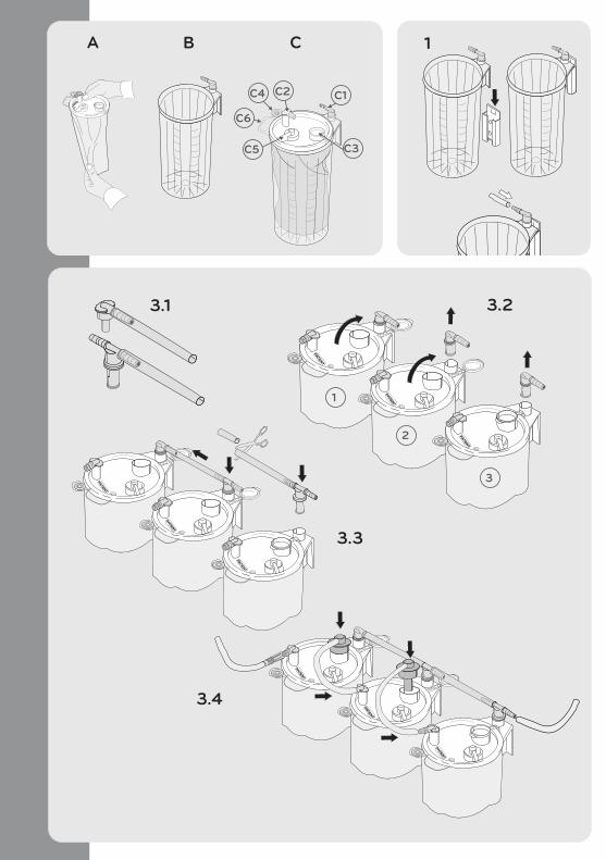
c. Suction bag parts: (Figure C)C1 Angled connector (gray, attached to the suction canister)C2 Patient connector (white, attached to the suction bag)C3 Serial port (used when bags are connected in series)C4 Patient connection plugC5 Overflow protectionC6 Handle
d. Other parts: The Serres trolley or Installation brackets (for rail, wall, table or bed), Vacuum tubing
Other optional system accessories are listed at the end of these Instructions.
III. INSTALLATIONFollow these steps to install the Suction Bag System:
1. Install the suction canister (Figure 1)Place the suction canister in a bracket in an upright position. Different brackets are available for installing the suction canister on the rail, wall, table or bed. The suction canister can also be mounted to the canister holder on the moveable Serres trolley.
2. Connect the vacuum tubingConnect the tubing from the vacuum source to the gray angled connector at the rear of the canister.
3. Insert the suction bagInsert the Suction Bag into a Suction Canister of equal size. The size (Volume) is marked both on the canister and on the lid of the suction bag. When placing the lid, make certain that the Suction Bag film is not caught between the canister and the lid.
!
!
The Serres Suction Bag System may only be installed and used by appropriately trained personnel. Only parts and accessories manufactured by Serres may be used with the Suction Bag System.The vacuum source and patient tubes are not manufactured by Serres. Use these products according to manufacturers' instructions.System components marked with the symbol are disposable. Cleaning, sterilizing or re-using disposable items is strictly prohibited. Solidifying agent is slippery when wet and might cause slip hazard if accidentally spilled on the floor.
WARNING
PRECAUTION
Persons using the Serres Suction Bag System should take appropriate safety precautions to protect themselves from coming into contact with patient liquids or secretions.
2
! Inspect System components before each use.Check each part of the Serres Suction Bag System to ensure that it is not damaged. Never use a damaged part.Check the "Use By" date on the System package
WARNING

A. Insert a single suction bag (Figure 2)
1. When the suction bag is wrapped and taped (Figure 2.1) Place the bag as is into the suction canister
2. When the suction bag is not wrapped and taped (Figure 2.2) Unfold the suction bag and place it into the suction canister.
B. Insert more than one suction bag (connection in series) (Figure 3)When large volumes of liquid are suctioned, the Suction Bags can be connected in a series using serial tubes, vacuum tubes and T-connectors. Up to 6 suction bags may be used at a time, according to the anticipated volume of liquid. 3-canister installation has been used in the illustration of this example.
1. Place a Suction Bag into a Suction Canister of the same size and attach the bags to the canisters by pressing the middle of the lid.
2. Remove the gray, angled connector on the canisters 2 and 3 (Figure 3.2) and open the serial ports on the suction bags 1 and 2.
3. Connect the Suction Canisters to each other using separate T-connectors and vacuum tubes. (Figure 3.3). Use scissors to cut the tube to a suitable length.
4. Connect the serial tube from the open serial port on the first suction bag to the patient connector on the next suction bag. (Figure 3.4)
¹
If the Dual Filter Suction bag is used it must be placed to the last canister (3).
5. Unfold the suction bag (Figure 4)Turn the vacuum source on while lightly pressing the middle of the lid (Figure 4, Part 1).
Once the suction bag is inflated, close the patient connector using your finger (Figure 4, Part 2) to create a seal between the lid and the suction canister.
6. Connect the patient tubeConnect the patient tube to the patient connector. The System is ready for use.
IV. USAGE / SUCTIONING
1. Turn the vacuum source on
When the suction is turned on, liquid will flow into the Suction Bag. When the Suction Bag is full, overflow protection turns off the suction to that bag to prevent liquid entering the suction source.
The scale on the suction canister displays the volume of liquid suctioned. The scale is accurate within +/- 100ml (cc).
V. Use of a pre-gelled suction bag (Figure 5)
Some suction bag models include a solidifying agent Figure 5 that solidifies the suctioned liquid. Use pre-gelled suction bags as you would use regular suction bags. Remember that when a solidifying agent is used / added to the suctioned liquid, the scale will measure the volume of suctioned liquid and the volume of solidifying agent added. 1l pre-gelled suction bag: includes 25 ml (cc) solidifier 2l pre-gelled suction bag: includes 50 ml (cc) solidifier 3l pre-gelled suction bag: includes 85 ml (cc) solidifierIn addition, note the normal tolerance of the suction canister scale. If you use separate sachets or a solidifying agent sold as separate powder, use 25 g (0.9oz) / 35 ml (cc) of substance per one liter (1,000 cc) of liquid. Note the warnings in the solidifying agent packet.
TIPS: For best performance, use a Vacuum Shift (Figure 12) for serial connections of largeamounts of liquid.
! Do not close the patient connector before the bag is fully inflated. Do not initiate use of the System until the Suction Bag is fully inflated and supported by the suction canister.
WARNING
TIPS: The vacuum source can be turned off if the procedure is not immediately started.
Watch video
Watch video
! Before use, ensure the vacuum has been createdWARNING
Watch video
! If the pre-gelled suction bags are used in serialconnections, the vacuum source must be on for the entire duration of the procedure.
PRECAUTION
TIPS: Gently squeezing the bag will help to mixthe solidifier and the liquids promoting solidification.
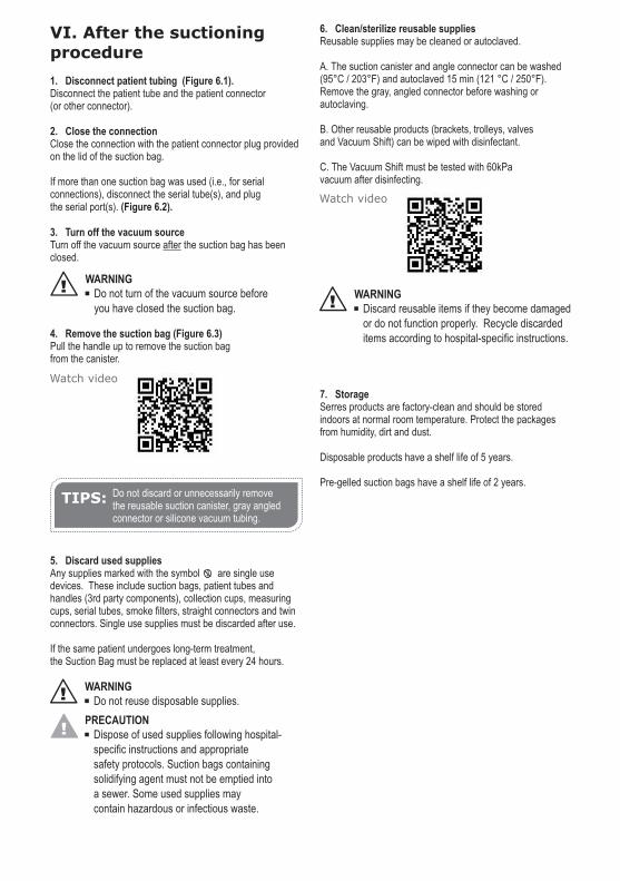
VI. After the suctioning procedure
1. Disconnect patient tubing (Figure 6.1).Disconnect the patient tube and the patient connector (or other connector).
2. Close the connectionClose the connection with the patient connector plug provided on the lid of the suction bag.
If more than one suction bag was used (i.e., for serial connections), disconnect the serial tube(s), and plug the serial port(s). (Figure 6.2).
3. Turn off the vacuum source Turn off the vacuum source after the suction bag has been closed.
4. Remove the suction bag (Figure 6.3)Pull the handle up to remove the suction bag from the canister.
5. Discard used supplies Any supplies marked with the symbol are single use devices. These include suction bags, patient tubes and handles (3rd party components), collection cups, measuring cups, serial tubes, smoke filters, straight connectors and twin connectors. Single use supplies must be discarded after use.
If the same patient undergoes long-term treatment, the Suction Bag must be replaced at least every 24 hours.
6. Clean/sterilize reusable suppliesReusable supplies may be cleaned or autoclaved.
A. The suction canister and angle connector can be washed (95°C / 203°F) and autoclaved 15 min (121 °C / 250°F). Remove the gray, angled connector before washing or autoclaving.
B. Other reusable products (brackets, trolleys, valves and Vacuum Shift) can be wiped with disinfectant.
C. The Vacuum Shift must be tested with 60kPavacuum after disinfecting.
7. StorageSerres products are factory-clean and should be stored indoors at normal room temperature. Protect the packages from humidity, dirt and dust.
Disposable products have a shelf life of 5 years.
Pre-gelled suction bags have a shelf life of 2 years.
! Do not turn of the vacuum source beforeyou have closed the suction bag.
WARNING
Watch video
2
! Do not reuse disposable supplies.WARNING
! Dispose of used supplies following hospital-specific instructions and appropriate safety protocols. Suction bags containingsolidifying agent must not be emptied intoa sewer. Some used supplies may contain hazardous or infectious waste.
PRECAUTION
TIPS: Do not discard or unnecessarily remove the reusable suction canister, gray angled connector or silicone vacuum tubing.
Watch video
! Discard reusable items if they become damaged or do not function properly. Recycle discarded items according to hospital-specific instructions.
WARNING

VII. ACCESSORIES
Optional accessories may be used with the Serres Suction Bag System.
1. Cups
A. Collection Cup (Figure 7)A collection cup may be inserted into a suction bag to collect samples from the suctioned liquid.
1. To insert, disconnect the white patient connector from the suction bag and attach the collection cup to the patient connector. Connect the patient tube to the angle connector of the cup lid.
2. To remove, detach the patient tube from the patient connector and close the connection. Detach the collection cup from the suction bag and turn the cup upside down. If necessary, add formalin through the connection in the bottom of the cup and close the connection.
B. Measuring Cup (Figure 8)A measuring cup is provided to measure the precise volume of suctioned liquid. The cup is accurate to within ± 5 ml (cc)for smaller volumes of liquid (up to 50 ml [cc]), and is accurate to within ± 10 ml (cc) for larger volumes of liquid (more than 50 ml [cc]).
1. To use, hang the measuring cup in an upright position on the lid of a suction bag and connect the tubes according to figure 8. Connect the patient tube to the angle connector in the middle of the measuring cup.
2. To empty (if desired), lift the cup from the bracket and tilt it so that liquid drains into the suction bag.
2. Connectors
A. Straight connector (Figure 9)A straight connector can be used with larger diameter patient tubing.
1. To use, replace the patient connector in the suction bag with the straight connector.
B. Twin connector (Figure 10)A twin connector can be used to connect two patient tubes to the same suction bag at the same time.
1. To use, replace the patient connector with the twin connector. During suction, close one of the patient tubes.
3. Smoke filter (Figure 11)The smoke filter can be used to prevent blockage of the overflow protection on the suction bag during procedures that produce very heavy smoke.
1. To use, replace the gray angled connector on the suction canister with a T-connector or Serres valve (Figure 14) and open the suction bag serial port. Press the smoke filter into the serial port so that the filter locks in place. 2. Connect the smoke filter tubing to the T-connector or Serres valve on the rear of the canister. 3. Turn the Serres valve lever. (Figure 11C)
The smoke filter can also be used in serial connection. To do so, install the smoke filter in the last suction bag of the serial connection.
Watch video
! Specimen jars are recommended to use to retain or transport specimens.
PRECAUTION
Watch video
Watch video
! The smoke filter does not prevent smoke from re-entering the room. Do not use the suction bag system as a smoke evacuator.
WARNING
! System components marked with the symbol are disposable. Cleaning, sterilizing or re-using disposable items is strictly prohibited.
WARNING
2
2
2
2
2
2

4. Vacuum Shift (Figure 12)The Vacuum Shift allows the vacuum power (suction) to be moved from one suction line to another. It can also be set to provide vacuum suction to two or more suction bags at the same time.
1. To use, Mount the Vacuum Shift on the device bracket, between two suction canisters using the connector on the Vacuum Shift.2. Use silicone tubing to connect the suction source to the Vacuum Shift, (Figure 12, connector A). 3. Connect the tubing from the suction canisters to the tube connectors on the right (Figure 12, connector B) and left sides (Figure 12, connector C) of the Vacuum Shift.4. Set the Vacuum Shift as below: a. No suction (Figure 12.1) b. Suction to the right--no suction to the left (Figure 12.2) c. Suction to the left figure--no suction to the right (Figure 12.3) d. Suction to the right and left (Figure 12.4)
Verify the Vacuum Shift setting before use. Vacuum strength may be reduced if the Shift is misaligned.
5. Valves
A. On-off valve (Figure 13)The on-off valve is used to turn suction on and off.
1. To use, Replace the gray, angled connector by inserting the on-off valve in its place. 2. Connect the tubing from the suction source to the on-off valve connector. 3. Open the valve to turn on suction. (Figure 13A). Close the valve to turn off the suction. (Figure 13B)
B. Serres valve used with smoke filter (Figure 14) The Serres valve can be used to operate the smoke filter following the same process described underneath.
C. Settings for Serres valve (Figure 11)Turn the valve to change settings:
1. Turn off suction (Figure 11A) 2. Turn on suction when smoke filter is not installed (Figure 11B)3. Turn on suction when smoke filter is installed (Figure 11C)
D. Control valve (Figure 15)The control valve can be set for use of a single Serres suction bag. Install the control valve inside the canister holder of a Serres trolley.
²
²(ref: 570940,570941)
To install:1. Detach the canister holder from the trolley.2. Open the holes (6 pcs) of the on-off valves on the top of the canister holder by pushing in the cover plates. (Figure 15A).3. Install the control valve inside the canister holder and rotate the valve until it reaches the bottom.4. Use three screws to attach the control valve to the canister holder.5. Re-install the canister holder on the trolley. Adjust the height of the holder and tighten the canister into place. (Figure 15B)6. Insert an on-off valve into the holes on top of the canister holder. Use one valve for each suction canister. If fewer than six suction canisters are used, close each remaining hole with a control valve plug. For suction to work properly, all six holes on the canister holder must either be fitted with an on-off valve or control valve plug.7. Connect the silicone tubing from the on-off valve to the angle connector of the suction canister. Check to confirm that it is not bent below so that suction is not impeded. 8. Connect the tube from the suction device to the tube connector on the bottom of the control valve. (Figure 15C)9. Check each on-off valve to make sure that it fits tightly.
To operate:1. Turn on the suction source2. Install the required number of suction canisters and suction bags3. Open one on-off valve to position "I"4. Connect the patient tube to the suction bag below the on-off valve5. When the suction bag is full, remove the patient tube, plug the full suction bag and turn the on-off valve to position "O."6. Turn the next on-off valve to position "I" and connect the patient tube to the suction bag below it.
6. Serres Splash-Vac (Figure 16)
The Serres Splash-Vac can be used to suction liquids from the floor. Connect the tubing to the patient connector of the suction bag.
NOTE! THE TUBING OF SPLASH-VAC IS MADE OF PVC PLASTIC. The product is not a medical device.
TIPS: For best performance, use only one suction canister at a time by turning the on-off valve on the first suction canister to "I." The on-off valve on all other suction canisters should be switched off by turning the on-off valve to position "O."
!

ONLY USE THE SERRES SUCTION BAG SYSTEM ACCORDING TO THE INSTRUCTIONS FOR USE. THE MANUFACTURER IS NOT
RESPONSIBLE FOR ANY OTHER USE OF THE SUCTION BAG SYSTEM.
Manufacturer:
Serres OyKeskustie 23
FI-61850 Kauhajoki as
Finland
www.serres.us

Manufacturer:
Serres OyKeskustie 23
FI-61850 Kauhajoki as
Finland
www.serres.us
177902 0
3/2
017