SERIES: VMS-300A DESCRIPTION: AC-DC POWER SUPPLY · cui.com CUI Inc │ SERIES: VMS-300A │...
10
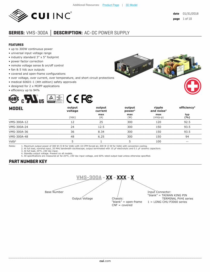
cui.com date 01/31/2018 page 1 of 10 SERIES: VMS-300A │ DESCRIPTION: AC-DC POWER SUPPLY MODEL output voltage output current output power 1 ripple and noise 2 efficiency 3 (Vdc) max (A) max (W) max (mVp-p) typ (%) VMS-300A-12 12 25 300 120 92.5 VMS-300A-24 24 12.5 300 150 93.5 VMS-300A-36 36 8.34 300 150 93.5 VMS-300A-48 48 6.25 300 150 94 Vstb 4 5 1 5 100 -- Notes: 1. Maximum output power of 300 W (5 W for Vstb) with 10 CFM forced air, 200 W (3 W for Vstb) with convection cooling. 2. At full load, nominal input, 20 MHz bandwidth oscilloscope, output terminated with 10 μF electrolytic and 0.1 μF ceramic capacitors. 3. At full load, 25°C, 230 Vac input. 4. Standby output voltage. Present on all models. 5. All specifications are measured at Ta=25°C, 230 Vac input voltage, and 60% rated output load unless otherwise specified. FEATURES • up to 300W continuous power • universal input voltage range • industry standard 3” x 5” footprint • power factor correction • remote voltage sense & on/off control • fan & 5 Vdc aux outputs • covered and open-frame configurations • over voltage, over current, over temperature, and short circuit protections • medical 60601-1 (4th edition) safety approvals • designed for 2 x MOPP applications • efficiency up to 94% PART NUMBER KEY Base Number VMS-300A - XX - XXX - X Output Voltage EN 60601-1 IEC 60601-1 ID xxxxxxxxxx www.tuv.com TUVRheinland Chassis: “blank” = open-frame CNF = covered Input Connector: “blank” = TAIWAN KING PIN TERMINAL PVHI series 1 = LONG CHU P3060 series Additional Resources: Product Page | 3D Model
Transcript of SERIES: VMS-300A DESCRIPTION: AC-DC POWER SUPPLY · cui.com CUI Inc │ SERIES: VMS-300A │...
cui.com
date 01/31/2018
page 1 of 10
SERIES: VMS-300A DESCRIPTION: AC-DC POWER SUPPLY
MODEL output voltage
output current
output power1
ripple and noise2
efficiency3
(Vdc)max(A)
max(W)
max(mVp-p)
typ(%)
VMS-300A-12 12 25 300 120 92.5
VMS-300A-24 24 12.5 300 150 93.5
VMS-300A-36 36 8.34 300 150 93.5
VMS-300A-48 48 6.25 300 150 94
Vstb4 5 1 5 100 --Notes: 1. Maximum output power of 300 W (5 W for Vstb) with 10 CFM forced air, 200 W (3 W for Vstb) with convection cooling. 2. At full load, nominal input, 20 MHz bandwidth oscilloscope, output terminated with 10 μF electrolytic and 0.1 μF ceramic capacitors. 3. At full load, 25°C, 230 Vac input. 4. Standby output voltage. Present on all models. 5. All specifications are measured at Ta=25°C, 230 Vac input voltage, and 60% rated output load unless otherwise specified.
FEATURES• up to 300W continuous power• universal input voltage range• industry standard 3” x 5” footprint• power factor correction• remote voltage sense & on/off control• fan & 5 Vdc aux outputs• covered and open-frame configurations• over voltage, over current, over temperature, and short circuit protections• medical 60601-1 (4th edition) safety approvals• designed for 2 x MOPP applications• efficiency up to 94%
PART NUMBER KEY
Base Number
VMS-300A - XX - XXX - X
Output Voltage
EN
60601-1IEC
60601-1
ID xxxxxxxxxxwww.tuv.com
TUVRheinland
Chassis:“blank” = open-frameCNF = covered
Input Connector:“blank” = TAIWAN KING PIN TERMINAL PVHI series1 = LONG CHU P3060 series
Additional Resources: Product Page | 3D Model
cui.com
date 01/31/2018 page 2 of 10CUI Inc SERIES: VMS-300A DESCRIPTION: AC-DC POWER SUPPLY
INPUTparameter conditions/description min typ max units
voltage 90 264 Vac
frequency 47 63 Hz
current at 100 Vacat 240 Vac
4.01.8
AA
inrush current at 240 Vac, 25°C, cold start 30 A
leakage current 0.3 mA
leakage current (enclosure/patient) 0.1 mA
power factor correction meets EN 61000-3-2
no load power consumption measured with the PS-ON signal configured to OFF 0.3 W
OUTPUTparameter conditions/description min typ max units
output capacitance
at 115/230 Vac, full load12 Vdc output models24 Vdc output models36 Vdc output models48 Vdc output models
25,00012,5005,0003,750
μFμFμFμF
initial set point accuracyat full load, 25°CVoVstb
±1±3
%%
line regulationhigh line to low line at full loadVoVstb
±0.5±1
%%
load regulationfrom full to 10% loadVoVstb
±1±5
%%
hold-up time at 115 Vac 16 ms
adjustability built in trim pot (VR) ±5 %
switching frequency at full load 60 80 kHz
temperature coefficient ±0.05 %/°C
PS-ON signal1power on
PS-ON 0 2 Vdc
PS-ON = 0V 4.5 mA
power offPS-ON = NC (internal circuit will drive PS-On to 11~16 Vdc)
PS-ON = NC 0 mA
power good (PG) TTL goes high 50~250 ms after powered onTTL goes low 5~20 ms before 90% Vo
standby output voltage 5 Vdc / 1 A
fan output 12 Vdc / 500 mANotes: 1. When not used, short PS-ON & signal GND.
PROTECTIONSparameter conditions/description min typ max units
over voltage protection
latch mode12 Vdc output models24 Vdc output models36 Vdc output models48 Vdc output models
15304356
VdcVdcVdcVdc
over current protection 130 150 180 %
short circuit protection hiccup, auto recovery
over temperature protection auto recovery (temperature of C37) 110 °C
Additional Resources: Product Page | 3D Model
cui.com
date 01/31/2018 page 3 of 10CUI Inc SERIES: VMS-300A DESCRIPTION: AC-DC POWER SUPPLY
SAFETY & COMPLIANCEparameter conditions/description min typ max units
isolation voltageinput to output (2MOPP) for 1 minuteinput to earth (1MOPP) for 1 minuteoutput to earth (1MOPP) for 1 minute
4,0001,5001,500
VacVacVac
isolation resistance 100 MΩ
safety approvals UL/cUL 60601-1, IEC 60601-1, EN 60601-1 (4th edition)
safety class class I
EMI/EMC EN55011, EN55022 Class B, EN55024, FCC Class B, EN61204-3, EN61000-6-1, EN61000-6-3, EN60601-1-2, EN61000-3-2, EN61000-3-3
MTBF as per MIL-HDBK-217F, at 115 Vac, 25°C, GB 100,000 hours
RoHS 2011/65/EUNotes: 1. The power supply is considered a component which will be installed into final equipment. The final equipment still must be tested to meet the necessary EMC directives.
ENVIRONMENTALparameter conditions/description min typ max units
operating temperature see derating curves -40 80 °C
storage temperature -40 85 °C
operating humidity non-condensing 93 %
operating altitude 3000 m
vibration2 as per MIL-STD-810F Table 514.5C-VIII; 15~2000 Hz for 1 hour on each axis for 3 hours 4 G
shock2 as per MIL-STD-810F Table 516.5, Table 516.5-1; for 10 ms on each axis 3 times 75 G
Notes: 2. See Installation Instructions for mounting requirements.
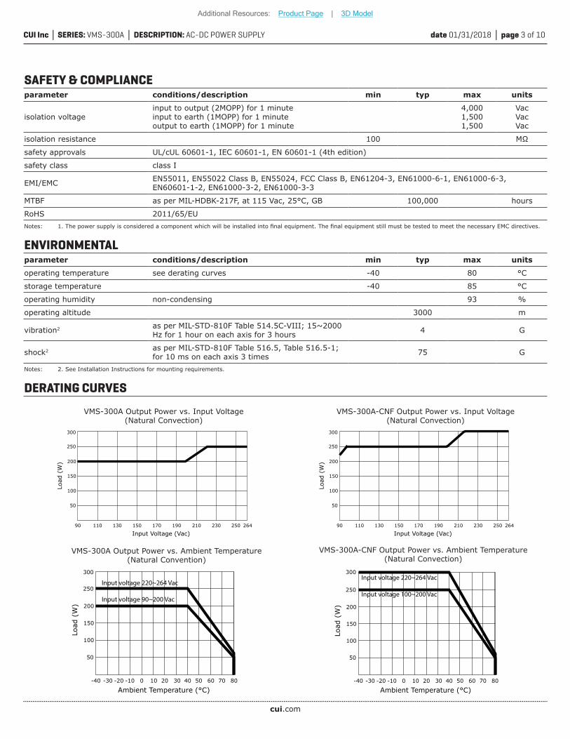
DERATING CURVES
VMS-300A Output Power vs. Input Voltage(Natural Convection)
Input Voltage (Vac)
Load
(W
)
90
150
200
250
100
50
110 130 150 170 190 210 230 250
300
264
VMS-300A-CNF Output Power vs. Input Voltage(Natural Convection)
Input Voltage (Vac)
Load
(W
)
90
150
200
250
100
50
110 130 150 170 190 210 230 250
300
264
VMS-300A-CNF Output Power vs. Ambient Temperature(Natural Convection)
Ambient Temperature (°C)
Load
(W
)
-40
150
200
250
100
50
-30 0 10 40 60 80-20 -10 20 30 50 70
300Input voltage 220~264 Vac
Input voltage 100~200 Vac
VMS-300A Output Power vs. Ambient Temperature(Natural Convention)
Ambient Temperature (°C)
Load
(W
)
-40
150
200
250
100
50
-30 0 10 40 60 80-20 -10 20 30 50 70
300
Input voltage 220~264 Vac
Input voltage 90~200 Vac
Additional Resources: Product Page | 3D Model
cui.com
date 01/31/2018 page 4 of 10CUI Inc SERIES: VMS-300A DESCRIPTION: AC-DC POWER SUPPLY
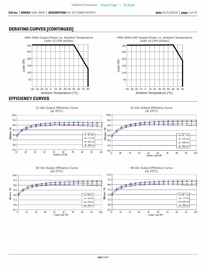
DERATING CURVES (CONTINUED)
VMS-300A-CNF Output Power vs. Ambient Temperature(with 10 CFM airflow)
Ambient Temperature (°C)
Load
(W
)
-40
150
200
250
100
50
-30 0 10 40 60 80-20 -10 20 30 50 70
300
VMS-300A Output Power vs. Ambient Temperature(with 10 CFM airflow)
Ambient Temperature (°C)
Load
(W
)
-40
150
200
250
100
50
-30 0 10 40 60 80-20 -10 20 30 50 70
300
EFFICIENCY CURVES
12 Vdc Output Efficiency Curve(at 25°C)
24 Vdc Output Efficiency Curve(at 25°C)
36 Vdc Output Efficiency Curve(at 25°C)
48 Vdc Output Efficiency Curve(at 25°C)
Additional Resources: Product Page | 3D Model
cui.com
date 01/31/2018 page 5 of 10CUI Inc SERIES: VMS-300A DESCRIPTION: AC-DC POWER SUPPLY
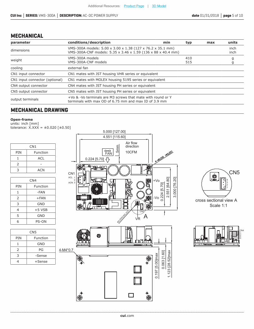
CN1
PIN Function
1 ACL
2 -
3 ACN
CN4
PIN Function
1 -FAN
2 +FAN
3 GND
4 +5 VSB
5 GND
6 PS-ON
CN5
PIN Function
1 GND
2 PG
3 -Sense
4 +Sense
1ACL
ACN+Vo
10CFM
Air flowdirection
FAN
CN11.
123
[28.
52]m
ax
0.19
7 [5
.00]
max
0.06
3 [1
.60]
5mm
4.551 [115.60]5.000 [127.00]
0.224 [5.70]
2.55
1 [6
4.80
]
3.00
0 [7
6.20
]
0.22
4 [5
.70]
23
-Vo
CN5
4321
4-M4*0.7
1
CN54
23
cross sectional view A Scale 1:1
123456
CN4
VR
Open-frameunits: inch [mm]tolerance: X.XXX = ±0.020 [±0.50]
MECHANICALparameter conditions/description min typ max units
dimensions VMS-300A models: 5.00 x 3.00 x 1.38 (127 x 76.2 x 35.1 mm)VMS-300A-CNF models: 5.35 x 3.46 x 1.59 (136 x 88 x 40.4 mm)
inchinch
weight VMS-300A modelsVMS-300A-CNF models
410515
gg
cooling external fan
CN1 input connector CN1 mates with JST housing VHR series or equivalent
CN1 input connector (optional) CN1 mates with MOLEX housing 5195 series or equivalent
CN4 output connector CN4 mates with JST housing PH series or equivalent
CN5 output connector CN5 mates with JST housing PH series or equivalent
output terminals +Vo & -Vo terminals are M3 screws that mate with round or Y terminals with max OD of 6.75 mm and max ID of 3.9 mm
MECHANICAL DRAWING
Additional Resources: Product Page | 3D Model
cui.com
date 01/31/2018 page 6 of 10CUI Inc SERIES: VMS-300A DESCRIPTION: AC-DC POWER SUPPLY
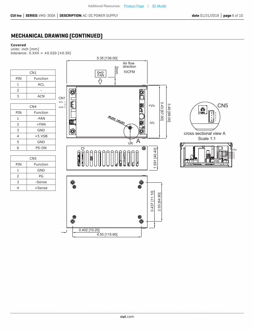
CN1
PIN Function
1 ACL
2 -
3 ACN
CN4
PIN Function
1 -FAN
2 +FAN
3 GND
4 +5 VSB
5 GND
6 PS-ON
CN5
PIN Function
1 GND
2 PG
3 -Sense
4 +Sense
+Vo
FAN
Air flowdirection10CFM
VRCN4
1
CN5
1.59
1 [4
0.40
]
5mm
3.46 [88.00]
5.35 [136.00]
3.43 [87.00]
-Vo
4
2.55
[64.
80]
0.43
7 [1
1.10
]
0.402 [10.20]4.55 [115.60]
23
1ACL
ACN
CN1
23
cross sectional view A Scale 1:1
123456
Coveredunits: inch [mm]tolerance: X.XXX = ±0.020 [±0.50]
MECHANICAL DRAWING (CONTINUED)
Additional Resources: Product Page | 3D Model
cui.com
date 01/31/2018 page 7 of 10CUI Inc SERIES: VMS-300A DESCRIPTION: AC-DC POWER SUPPLY
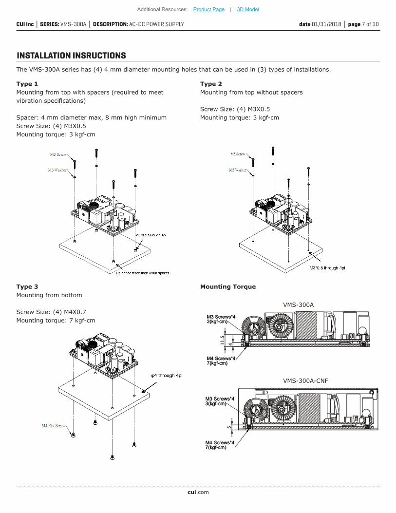
INSTALLATION INSRUCTIONS
Type 1Mounting from top with spacers (required to meet vibration specifications)
Spacer: 4 mm diameter max, 8 mm high minimumScrew Size: (4) M3X0.5Mounting torque: 3 kgf-cm
Type 2Mounting from top without spacers
Screw Size: (4) M3X0.5Mounting torque: 3 kgf-cm
Type 3Mounting from bottom
Screw Size: (4) M4X0.7Mounting torque: 7 kgf-cm
The VMS-300A series has (4) 4 mm diameter mounting holes that can be used in (3) types of installations.
Mounting Torque
VMS-300A-CNF
VMS-300A
Additional Resources: Product Page | 3D Model
cui.com
date 01/31/2018 page 8 of 10CUI Inc SERIES: VMS-300A DESCRIPTION: AC-DC POWER SUPPLY
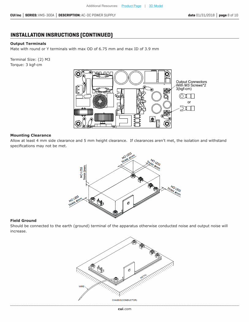
INSTALLATION INSRUCTIONS (CONTINUED)Output TerminalsMate with round or Y terminals with max OD of 6.75 mm and max ID of 3.9 mm
Terminal Size: (2) M3Torque: 3 kgf-cm
Mounting ClearanceAllow at least 4 mm side clearance and 5 mm height clearance. If clearances aren’t met, the isolation and withstand specifications may not be met.
Field GroundShould be connected to the earth (ground) terminal of the apparatus otherwise conducted noise and output noise will increase.
Additional Resources: Product Page | 3D Model
cui.com
date 01/31/2018 page 9 of 10CUI Inc SERIES: VMS-300A DESCRIPTION: AC-DC POWER SUPPLY
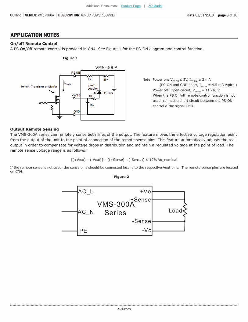
On/off Remote ControlA PS On/Off remote control is provided in CN4. See Figure 1 for the PS-ON diagram and control function.
APPLICATION NOTES
VMS-300A
Figure 1
Note: Power on: VPS-ON ≤ 2V, IPS-ON ≥ 2 mA (PS-ON and GND short, IPS-ON = 4.5 mA typical) Power off: Open circuit, VPS-ON = 11~16 V When the PS On/off remote control function is not used, connect a short circuit between the PS-ON control & the signal GND.
Output Remote SensingThe VMS-300A series can remotely sense both lines of the output. The feature moves the effective voltage regulation point from the output of the unit to the point of connection of the remote sense pins. This feature automatically adjusts the real output in order to compensate for voltage drops in distribution and maintain a regulated voltage at the point of load. The remote sense voltage range is as follows:
[(+Vout) – (-Vout)] – [(+Sense) – (-Sense)] ≤ 10% Vo_nominal
If the remote sense is not used, the sense pins should be connected locally to the respective Vout pins. The remote sense pins are located on CN4.
AC_L
AC_N
PE
VMS-300ASeries
+Vo
-Vo
+Sense
-Sense
Load
Figure 2
Additional Resources: Product Page | 3D Model
date 01/31/2018 page 10 of 10CUI Inc SERIES: VMS-300A DESCRIPTION: AC-DC POWER SUPPLY
CUI offers a two (2) year limited warranty. Complete warranty information is listed on our website.
CUI reserves the right to make changes to the product at any time without notice. Information provided by CUI is believed to be accurate and reliable. However, no responsibility is assumed by CUI for its use, nor for any infringements of patents or other rights of third parties which may result from its use.
CUI products are not authorized or warranted for use as critical components in equipment that requires an extremely high level of reliability. A critical component is any component of a life support device or system whose failure to perform can be reasonably expected to cause the failure of the life support device or system, or to affect its safety or effectiveness.
Headquarters20050 SW 112th Ave.Tualatin, OR 97062800.275.4899
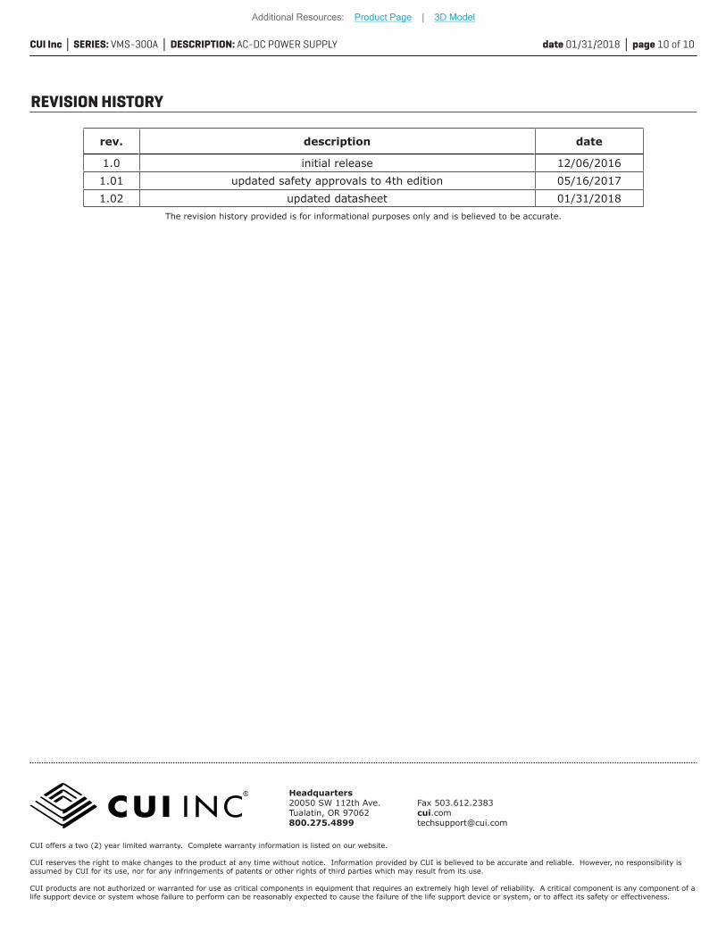
rev. description date
1.0 initial release 12/06/20161.01 updated safety approvals to 4th edition 05/16/20171.02 updated datasheet 01/31/2018
The revision history provided is for informational purposes only and is believed to be accurate.
REVISION HISTORY
Additional Resources: Product Page | 3D Model