SERIES SHEAR WALL SYSTEM - Building in...
64
Product Catalog 6-12 SHEAR WALL SYSTEM SERIES
-
Upload
nguyenhanh -
Category
Documents
-
view
233 -
download
2
Transcript of SERIES SHEAR WALL SYSTEM - Building in...
Product Catalog
6-12
S H E A R W A L L S Y S T E M
S E R I E S
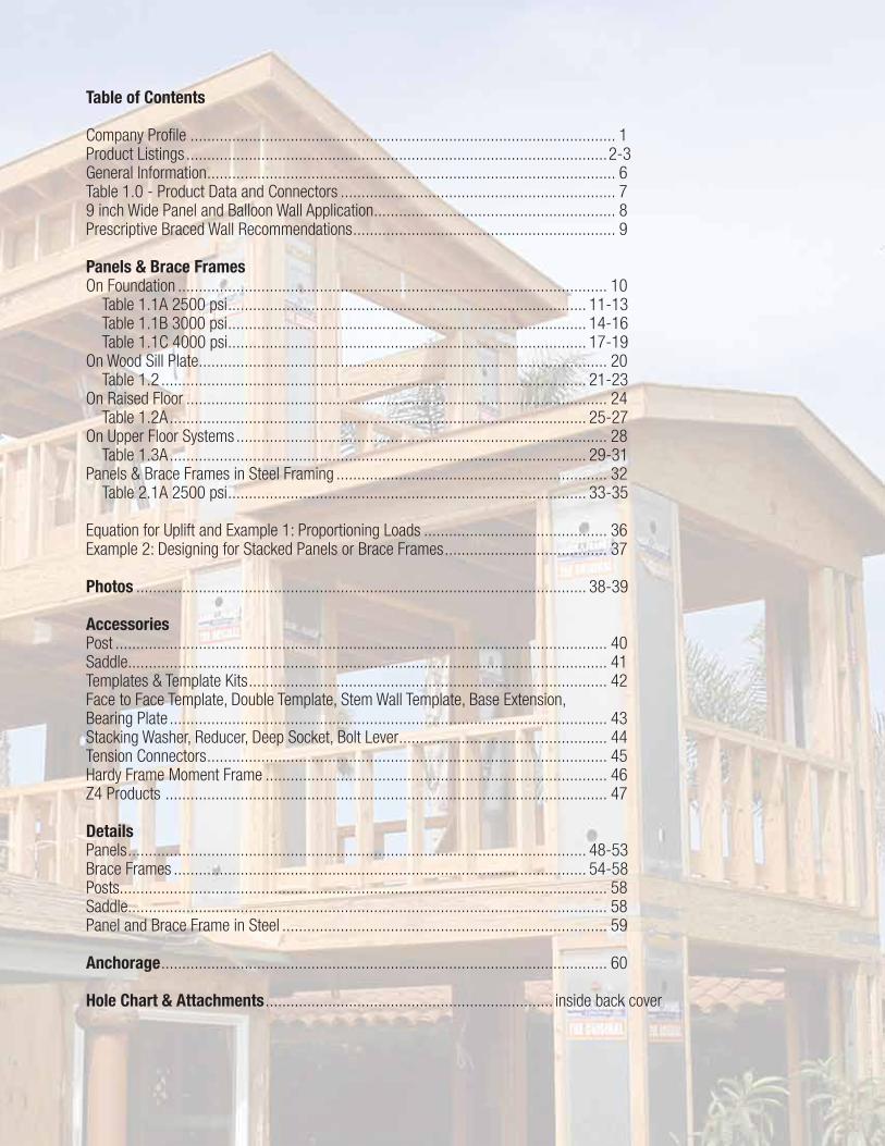
Table of Contents
Company Profile ...................................................................................................... 1Product Listings ..................................................................................................... 2-3General Information .................................................................................................. 6Table 1.0 - Product Data and Connectors .................................................................. 79 inch Wide Panel and Balloon Wall Application .......................................................... 8Prescriptive Braced Wall Recommendations ............................................................... 9
Panels & Brace FramesOn Foundation ....................................................................................................... 10 Table 1.1A 2500 psi ...................................................................................... 11-13 Table 1.1B 3000 psi ...................................................................................... 14-16 Table 1.1C 4000 psi ...................................................................................... 17-19On Wood Sill Plate .................................................................................................. 20 Table 1.2 ...................................................................................................... 21-23On Raised Floor ..................................................................................................... 24 Table 1.2A .................................................................................................... 25-27On Upper Floor Systems ......................................................................................... 28 Table 1.3A .................................................................................................... 29-31Panels & Brace Frames in Steel Framing ................................................................. 32 Table 2.1A 2500 psi ...................................................................................... 33-35
Equation for Uplift and Example 1: Proportioning Loads ............................................ 36Example 2: Designing for Stacked Panels or Brace Frames ....................................... 37
Photos ............................................................................................................ 38-39
AccessoriesPost ...................................................................................................................... 40Saddle................................................................................................................... 41Templates & Template Kits ...................................................................................... 42Face to Face Template, Double Template, Stem Wall Template, Base Extension, Bearing Plate ......................................................................................................... 43Stacking Washer, Reducer, Deep Socket, Bolt Lever .................................................. 44Tension Connectors ................................................................................................ 45Hardy Frame Moment Frame .................................................................................. 46Z4 Products .......................................................................................................... 47
DetailsPanels .............................................................................................................. 48-53Brace Frames ................................................................................................... 54-58Posts..................................................................................................................... 58Saddle................................................................................................................... 58Panel and Brace Frame in Steel .............................................................................. 59
Anchorage ........................................................................................................... 60
Hole Chart & Attachments ..................................................................... inside back cover
TM
TM
1
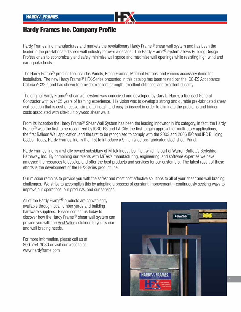
Hardy Frames Inc. Company Profile
Hardy Frames, Inc. manufactures and markets the revolutionary Hardy Frame® shear wall system and has been the leader in the pre-fabricated shear wall industry for over a decade. The Hardy Frame® system allows Building Design Professionals to economically and safely minimize wall space and maximize wall openings while resisting high wind and earthquake loads.
The Hardy Frame® product line includes Panels, Brace Frames, Moment Frames, and various accessory items for installation. The new Hardy Frame® HFX-Series presented in this catalog has been tested per the ICC-ES Acceptance Criteria AC322, and has shown to provide excellent strength, excellent stiffness, and excellent ductility.
The original Hardy Frame® shear wall system was conceived and developed by Gary L. Hardy, a licensed General Contractor with over 25 years of framing experience. His vision was to develop a strong and durable pre-fabricated shear wall solution that is cost effective, simple to install, and easy to inspect in order to eliminate the problems and hidden costs associated with site-built plywood shear walls.
From its inception the Hardy Frame® Shear Wall System has been the leading innovator in it's category, in fact, the Hardy Frame® was the first to be recognized by ICBO-ES and LA City, the first to gain approval for multi-story applications, the first Balloon Wall application, and the first to be recognized to comply with the 2003 and 2006 IBC and IRC Building Codes. Today, Hardy Frames, Inc. is the first to introduce a 9 inch wide pre-fabricated steel shear Panel.
Hardy Frames, Inc. is a wholly owned subsidiary of MiTek Industries, Inc., which is part of Warren Buffett’s Berkshire Hathaway, Inc. By combining our talents with MiTek’s manufacturing, engineering, and software expertise we have amassed the resources to develop and offer the best products and services for our customers. The latest result of these efforts is the development of the HFX-Series product line.
Our mission remains to provide you with the safest and most cost effective solutions to all of your shear and wall bracing challenges. We strive to accomplish this by adopting a process of constant improvement – continuously seeking ways to improve our operations, our products, and our services.
All of the Hardy Frame® products are conveniently available through local lumber yards and building hardware suppliers. Please contact us today to discover how the Hardy Frame® shear wall system can provide you with the Best Value solutions to your shear and wall bracing needs.
For more information, please call us at 800-754-3030 or visit our website at www.hardyframe.com

TM
TM
2
PRODUCT LISTINGS
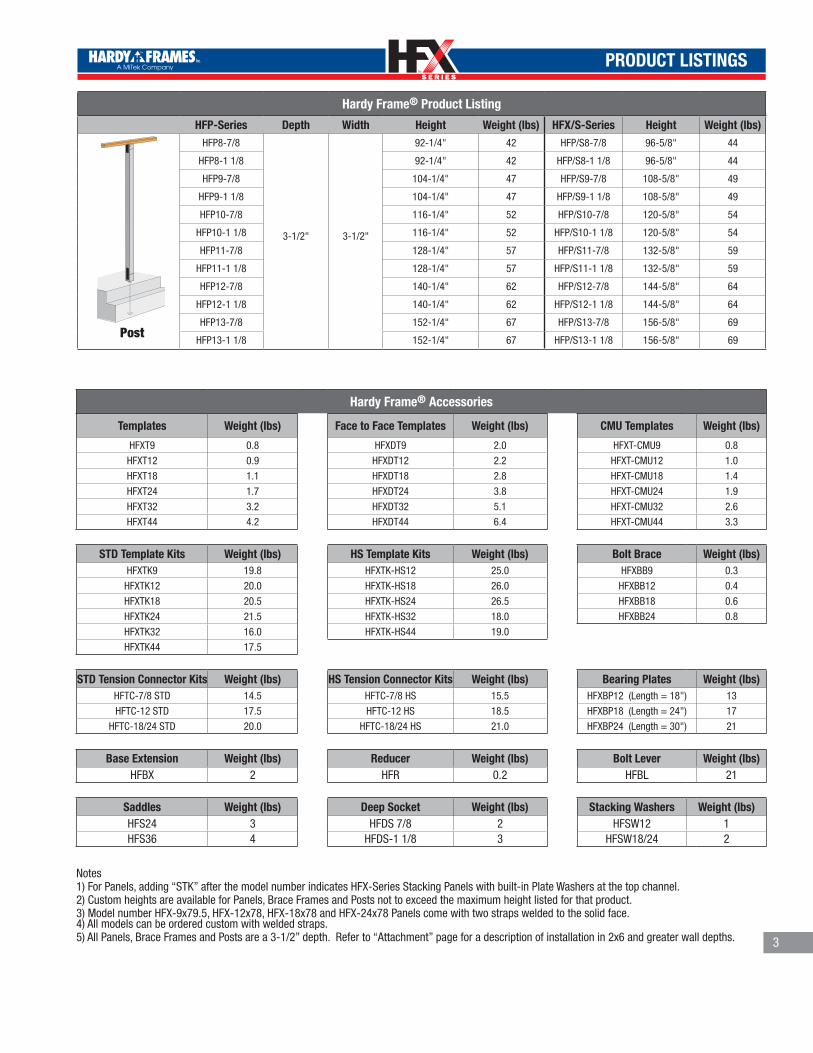
Hardy Frame® Product Listing
HFX-Series Depth (in) Width (in) Height (in) Weight (lbs) HFX/S-Series Height (in) Weight (lbs)
HFX-9x79.5
3-1/2"
9"79-1/2" 81 NA
HFX-9X8 93-3/4" 95 HFX/S-9x8 96 5/8" 98
HFX-12x78
12"
78" 91 NA
HFX-12x8 92-1/4" 106 HFX/S-12x8 96-5/8" 111
HFX-12x9 104-1/4" 116 HFX/S-12x9 108-5/8" 121
HFX-12x10 116-1/4" 128 HFX/S-12x10 120-5/8" 133
HFX-18x78
18"
78" 113 NA
HFX-18x8 92-1/4" 131 HFX/S-18x8 96-5/8" 137
HFX-18x9 104-1/4" 144 HFX/S-18x9 108-5/8" 150
HFX-18x10 116-1/4" 158 HFX/S-18x10 120-5/8" 164
HFX-18x11 128-1/4" 177 HFX/S-18x11 132-5/8" 183
HFX-18x12 140-1/4" 190 HFX/S-18x12 144-5/8" 196
HFX-18x13 152-1/4" 203 HFX/S-18x13 156-5/8" 209
HFX-24x78
24"
78" 148 NA
HFX-24x8 92-1/4" 172 HFX/S-24x8 96-5/8" 180
HFX-24x9 104-1/4" 190 HFX/S-24x9 108-5/8" 198
HFX-24x10 116-1/4" 209 HFX/S-24x10 120-5/8" 217
HFX-24x11 128-1/4" 233 HFX/S-24x11 132-5/8" 241
HFX-24x12 140-1/4" 251 HFX/S-24x12 144-5/8" 259
HFX-24x13 152-1/4" 269 HFX/S-24x13 156-5/8" 277
HFX-18x14
3-1/2”
18”
164-1/4" 221 HFX/S-18x14 168 5/8” 227
HFX-18x15 176-1/4" 237 HFX/S-18x15 180 5/8” 243
HFX-18x16 188-1/4" 250 HFX/S-18x16 192 5/8” 256
HFX-18x17 200-1/4" 264 HFX/S-18x17 204 5/8” 270
HFX-18x18 212-1/4" 283 HFX/S-18x18 216 5/8” 289
HFX-18x19 224-1/4" 296 HFX/S-18x19 228 5/8” 302
HFX-18x20 236-1/4" 309 HFX/S-18x20 240 5/8” 315
HFX-24x14
24”
164-1/4" 290 HFX/S-24x14 168 5/8” 298
HFX-24x15 176-1/4" 311 HFX/S-24x15 180 5/8” 319
HFX-24x16 188-1/4" 329 HFX/S-24x16 192 5/8” 337
HFX-24x17 200-1/4" 348 HFX/S-24x17 204 5/8” 356
HFX-24x18 212-1/4" 372 HFX/S-24x18 216 5/8” 380
HFX-24x19 224-1/4" 390 HFX/S-24x19 228 5/8” 398
HFX-24x20 236-1/4" 408 HFX/S-24x20 240 5/8” 416
HFX-32x8
3-1/2”
32”
92-1/4" 138 HFX/S-32x8 96-5/8" 145
HFX-32x9 104-1/4" 163 HFX/S-32x9 108-5/8" 170
HFX-32x10 116-1/4" 188 HFX/S-32x10 120-5/8" 195
HFX-32x11 128-1/4" 213 HFX/S-32x11 132-5/8" 220
HFX-32x12 140-1/4" 238 HFX/S-32x12 144-5/8" 245
HFX-32x13 152-1/4" 263 HFX/S-32x13 156-5/8" 271
HFX-44x8 92-1/4" 156 HFX/S-44x8 96-5/8" 163
44”
HFX-44x9 104-1/4" 181 HFX/S-44x9 108-5/8" 189
HFX-44x10 116-1/4" 206 HFX/S-44x10 120-5/8" 214
HFX-44x11 128-1/4" 231 HFX/S-44x11 132-5/8" 239
HFX-44x12 140-1/4" 256 HFX/S-44x12 144-5/8" 264
HFX-44x13 152-1/4" 281 HFX/S-44x13 156-5/8" 289
Panel
Balloon Panel
Brace Frame
TM
TM
PRODUCT LISTINGS
3
Hardy Frame® Product Listing
HFP-Series Depth Width Height Weight (lbs) HFX/S-Series Height Weight (lbs)HFP8-7/8
3-1/2" 3-1/2"
92-1/4" 42 HFP/S8-7/8 96-5/8" 44
HFP8-1 1/8 92-1/4" 42 HFP/S8-1 1/8 96-5/8" 44
HFP9-7/8 104-1/4" 47 HFP/S9-7/8 108-5/8" 49
HFP9-1 1/8 104-1/4" 47 HFP/S9-1 1/8 108-5/8" 49
HFP10-7/8 116-1/4" 52 HFP/S10-7/8 120-5/8" 54
HFP10-1 1/8 116-1/4" 52 HFP/S10-1 1/8 120-5/8" 54
HFP11-7/8 128-1/4" 57 HFP/S11-7/8 132-5/8" 59
HFP11-1 1/8 128-1/4" 57 HFP/S11-1 1/8 132-5/8" 59
HFP12-7/8 140-1/4" 62 HFP/S12-7/8 144-5/8" 64
HFP12-1 1/8 140-1/4" 62 HFP/S12-1 1/8 144-5/8" 64
HFP13-7/8 152-1/4" 67 HFP/S13-7/8 156-5/8" 69
HFP13-1 1/8 152-1/4" 67 HFP/S13-1 1/8 156-5/8" 69Post
Hardy Frame® Accessories
Templates Weight (lbs) Face to Face Templates Weight (lbs) CMU Templates Weight (lbs)
HFXT9 0.8 HFXDT9 2.0 HFXT-CMU9 0.8
HFXT12 0.9 HFXDT12 2.2 HFXT-CMU12 1.0
HFXT18 1.1 HFXDT18 2.8 HFXT-CMU18 1.4
HFXT24 1.7 HFXDT24 3.8 HFXT-CMU24 1.9
HFXT32 3.2 HFXDT32 5.1 HFXT-CMU32 2.6
HFXT44 4.2 HFXDT44 6.4 HFXT-CMU44 3.3
STD Template Kits Weight (lbs) HS Template Kits Weight (lbs) Bolt Brace Weight (lbs)HFXTK9 19.8 HFXTK-HS12 25.0 HFXBB9 0.3
HFXTK12 20.0 HFXTK-HS18 26.0 HFXBB12 0.4
HFXTK18 20.5 HFXTK-HS24 26.5 HFXBB18 0.6
HFXTK24 21.5 HFXTK-HS32 18.0 HFXBB24 0.8
HFXTK32 16.0 HFXTK-HS44 19.0 HFXTK44 17.5
STD Tension Connector Kits Weight (lbs) HS Tension Connector Kits Weight (lbs) Bearing Plates Weight (lbs)HFTC-7/8 STD 14.5 HFTC-7/8 HS 15.5 HFXBP12 (Length = 18") 13
HFTC-12 STD 17.5 HFTC-12 HS 18.5 HFXBP18 (Length = 24") 17
HFTC-18/24 STD 20.0 HFTC-18/24 HS 21.0 HFXBP24 (Length = 30") 21
Base Extension Weight (lbs) Reducer Weight (lbs) Bolt Lever Weight (lbs)HFBX 2 HFR 0.2 HFBL 21
Saddles Weight (lbs) Deep Socket Weight (lbs) Stacking Washers Weight (lbs)HFS24 3 HFDS 7/8 2 HFSW12 1HFS36 4 HFDS-1 1/8 3 HFSW18/24 2
Notes1) For Panels, adding “STK” after the model number indicates HFX-Series Stacking Panels with built-in Plate Washers at the top channel.2) Custom heights are available for Panels, Brace Frames and Posts not to exceed the maximum height listed for that product.3) Model number HFX-9x79.5, HFX-12x78, HFX-18x78 and HFX-24x78 Panels come with two straps welded to the solid face.4) All models can be ordered custom with welded straps.5) All Panels, Brace Frames and Posts are a 3-1/2” depth. Refer to “Attachment” page for a description of installation in 2x6 and greater wall depths.

TM
TM
GENERAL INFORMATION
4
Code Evaluations:
ICC-Evaluation Service ESR-2089 Report LA City Research Report RR-25759
Note: For the latest product and application evaluations refer to the current Report publication.
Product Use: The Hardy Frame® products are designed and manufactured for the specific purposes described in this catalog. Any changes to the products or in the installation procedures must be approved by the Building Design Professional and are the sole responsibility of the designer.
Quality Statement:
Hardy Frames, Inc. warrants to its customers that its products are free from material defects of manufacture or design, and will perform in substantial accordance with published specifications, if properly used.
Testing:
Hardy Frames, Inc. performs extensive testing on all of the Hardy Frame® structurally rated products. All final testing is conducted by a third party testing laboratory.
Material:
Hardy Frame® Panels, Brace Frames and Posts are manufactured from prime quality steel which meets the requirements of ASTM A 653 SS Grade 50 steel and ASTM A 36 hot-rolled steel built in at hold down connections.
Finish:
All galvanized steel have a minimum G60 hot-dipped galvanized zinc coating.
Threaded Rod/Hold Down Bolts
Unless noted otherwise the “STD” hold downs are ASTM F 1554 grade 36, and the “HS” (high strength) are ASTM A 193 grade B7 or equivalent.

TM
TM
GENERAL INFORMATION
5
Notes to the Specifier:
• The allowable loads shown in this catalog are based on Allowable Stress Design (ASD)
methodology.
• The published allowable design loads for the Hardy Frame® Panels and Brace Frames are
based on calculations and testing.
• For the Hardy Frame® Panels and Brace Frames, the allowable design loads may change
depending on the type of support below. Please be sure to refer to the proper table and
installation details for accurate load values and proper installation.
• Please be clear as to the surface you want the Hardy Frame® Panel or Brace Frame to be
installed on i.e.: on concrete, mudsill, etc.
• For a combination of over-turning and gravity loads the specifier must review and
check the bearing pressure on the structure below.
• The allowable design values for the Hardy Frame® Panels and Brace Frames shown in these
tables are for the 2006 IBC code.
Notes to the Framer:• Install all specified fasteners in accordance with the instructions of this catalog.
•When necessary, all field welding should be done in accordance with A.W.S. standards.
WARNING: Welding galvanized steel may produce harmful fumes and should be performed in
well-ventilated environments. Follow proper welding procedures and safety precautions.
•Washers are required under the head or nut of all bolted connections.
• Please refer to the proper installation specifications and details as provided in the plans.
General Notes:• Hardy Frames, Inc. reserves the right to change specifications, designs, and models without
notice and liability of such changes.
• The information presented in this catalog supercedes all information published in previous
documents and publications.
• This catalog is designed as a general reference for the Hardy Frame® products. For more
specific and most up to date information, please visit our website at www.
hardyframe.com or contact us directly at 800-754-3030.
• For installations involving unusual or extreme applications and conditions, please contact
Hardy Frames, Inc. at 800-754-3030.
• This catalog may not be reproduced in whole or in part without the written permission of
Hardy Frames, Inc.
CUSTOMER SERVICE
At Hardy Frames, Inc. pre-manufactured shear walls are our core business. From the beginning, customer service has been a top priority. Because we are focused on shear walls and have a strong commitment to service, we can provide you with the best support in the industry.
To the Design Professional this means prompt and correct technical answers and full design solutions that are backed by extensive testing and research. From providing allowable design loads to addressing specific repairs you can always count on our answers.
To the Building Official, our Code Reports and Typical Installation Details will make the plan check process and field inspection easier.
To the Installer, our background and knowledge in framing and construction allows us to communicate with the field and have an understanding of the installation from the point of view of the installer. Quick responses are a must and project delays are avoided at all costs. Help is available by telephone, or by one of our many field representatives with real field experience.
To all parties, in addition to literature, details and telephone support, our company provides jobsite visits, seminars, and personal training sessions. We respond to our customers and you can rest assured that we will be there for you when you need us.
How can we help you today?

TM
TM
GENERAL INFORMATION
6
General Information
The Hardy Frame® HFX-Series Panels and Brace Frames combine the most desirable properties for a shear wall: strength, stiffness, and ductility. This revolutionary system has been tested and evaluated under the ICC-Evaluation Service AC322 Acceptance Criteria and has been proven to provide the highest allowable shear loads in the industry combined with abundant ductility for a seismic “R” value of 6.5. Along with its superior engineering properties, the HFX-Series is easier than ever to install, is code listed for varied installations including on floor systems and stacking conditions with practical anchorage solutions for standard as well as high strength hold down rods.
New features presented in this catalog include:•New tables for Installation on 2500, 3000 and 4000 psi concrete. • All tables provide allowable values with a 1k, 3.5k and 6.5k axial load applied.• All tables have been checked for bearing pressure limits on supporting material below.• Allowable design values for standard and high strength hold down anchors.• Provisions to calculate reduced uplift when axial loads are applied.• Anchorage Solutions provided per ACI 318, Appendix D.
Hardy Frame® HFX-Series Panels are available in widths of 9, 12, 18 and 24-inches and in heights that correspond to a standard portal (78-inches) and standard wood stud lengths. For slab or curb installations simply secure to the foundation with two 1-1/8-inch diameter hold down anchors and connect the top channel to a collector above with 1/4-inch diameter screws through pre-punched holes. No connections are required to the edges or to either face. Hardy Frame® HFX-Series Brace Frames are either 32 or 44-inches wide and as with Panels, are fabricated to standard wood stud lengths. Hold down anchors for Brace Frames are 7/8-inch diameter and may be either standard or high strength for increased allowable loads. Connections to the foundation require two 7/8-inch diameter standard grade hold down anchors. Top connections are accomplished with 1/4-inch diameter screws into the collector above. No other connections are required but field studs are provided for easy attachment of surface finishes with self tapping screws.
Specifying Tips
Foundation Plan- Provide Panel or Brace Frame Model Number - Provide Embed Call-Out from the Hardy Frame Anchorage Details. - Provide bottom connection detail reference (on concrete, on mudsill, on raised floor, etc.)NOTE: Embedment information and the base connection / supporting material below effect the allowable loads. To achieve the appropriate allowable values it is necessary to convey the information provided above to the installer.
First Floor Framing Plan- Provide Panel or Brace Frame Model Number - For single story installations - Provide top connection detail reference (to the top plates, with a 2x filler, continuous header above, etc.)- For multi story installations - Provide floor to floor connection detail reference (straight stack, stagger stack, etc.)
ReminderHardy Frame® Panels and Brace Frames are built to standard wood stud heights. Top connections are made with 1/4 x 4-1/2 inch long screws when installing a 2x filler above. Hardy Frame® Bearing Plates are included in the calculations for wood floor system tables. Check that Panels are located at least 3-inches from an outside corner to accommodate the Bearing Plate. Other installations by the Building Design Professional are allowed provided the bearing pressure and code drift limit are considered. Hardy Frame® Brace Frames do not use Bearing Plates.
NOMINAL HEIGHTACTUAL WIDTHPRODUCT SERIES
PANEL NOMENCLATUREHFX-18 x 9
Ca 1, 2leROD GRADEROD DIAMETER
ANCHORAGE NOMENCLATURE1 1/8-STD-14-20

TM
TM
PANELS & BRACE FRAMES
7
12" Hardy Frame®
HFX-Series Panel
Hole Pattern Bottom
Hole Pattern TopHole Pattern Top
Hole Pattern Top
Hole Pattern Top
1 3/4" 1 3/4" 2 5/8"
2 5/8" 2 5/8"6 1/2"
5 3/4" 5 3/4"
31"
20 1/2"
6 1/2"
2 5/8"8 1/2"
18 3/4"
12 3/4"12"
24"
44"
32"
18"
Hole Pattern Bottom
Hole Pattern Top & Bottom
Hole Pattern Bottom
24" Hardy Frame® HFX-Series Panel
44" Hardy Frame® HFX-Series Brace Frame
18" Hardy Frame®
HFX-Series Panel
32" Hardy Frame® HFX-Series Brace Frame
9" Hardy Frame®
HFX-Series Panel
Hole Pattern Bottom
1 3/4" 1 3/4"5 1/2"9"
Notes1. The Builder Design Professional is allowed to design alternate anchorage to
meet specific design conditions including design loads lower than the allowable and reduced tension resulting from vertical axial loads applied.
2. STD Hold Down rods must comply with ASTM F 1554 Grade 36. HS Hold Down rods must comply with a high strength steel specification, High Strength rods include but are not limited to ASTM F 1554 Grade 105, ASTM A 193 Grade B7 and ASTM A 354 Grade BD.
3. Screws are 1/4-inch diameter USP-WS Series (ESR-2761) or equal with a minimum allowable design value of 311 lbs. (excluding any duration of load stress increase) based on connecting metal (No. 12 gage) to wood (specific gravity of 0.50 or greater).
4. Top screw length is 3-inches when attaching directly to the collector. When installing a 2-by wood filler (specific gravity of 0.5 or greater) at the top connection, the minimum screw length is 4-1/2 inches.
5. Bottom screw length is 4-1/2 inches at Panel and Brace Frame connections, 3-inches at Hardy Frame® Bearing Plate.
SEE ANCHORAGE DETAILS FOR MORE SPECIFIC INFORMATION
Ca 1, 2leROD GRADEROD DIAMETER
ANCHORAGE NOMENCLATURE1 1/8-STD-14-20
HFX Series Bolt Pattern
Hardy Frame® HFX-Series Panel - Dimensions & Connectors
Model Number
Net Height
(in)
Width (in)
Depth (in)
AnchorageCall-Out for STD Rods 1
Dia-Grade-le-Ca1,2
AnchorageCall-Out forHS Rods 1
Dia-Grade-le-Ca1,2
Top Screw Qty
2,3 (ea)
BottomScrew Qty
2,4 (ea)
Edge Screw QTY Available5
(ea)
HFX-9x79.5 79 1/29 3-1/2 1 1/8-STD-10-15 NA 5 NA 4
HFX-9x8 93 3/4HFX-12x78 78
12 3-1/2 1 1/8-STD-14-20 1 1/8-HS-14-20
7
64HFX-12x8 92 1/4
6HFX-12x9 104 1/4HFX-12x10 116 1/4 5HFX-18x78 78
18 3-1/2
1 1/8-STD-14-20 1 1/8-HS-20-30
10
10
4HFX-18x8 92 1/4HFX-18x9 104 1/4HFX-18x10 116 1/4
5HFX-18x11 128 1/4HFX-18x12 140 1/4
6HFX-18x13 152 1/4HFX-18x14 164 1/4
NA 1 1/8-HS-13-20 NA
6HFX-18x15 176 1/4HFX-18x16 188 1/4HFX-18x17 200 1/4
7HFX-18x18 212 1/4HFX-18x19 224 1/4
8HFX-18x20 236 1/4HFX-24x78 78
24 3-1/2
1 1/8-STD-14-20 1 1/8-HS-20-30
18 164HFX-24x8 92 1/4 15
14
HFX-24x9 104 1/4
14
HFX-24x10 116 1/45
HFX-24x11 128 1/4HFX-24x12 140 1/4
6HFX-24x13 152 1/4HFX-24x14 164 1/4
NA 1 1/8-HS-18-27 NA
6HFX-24x15 176 1/4HFX-24x16 188 1/4HFX-24x17 200 1/4
7HFX-24x18 212 1/4HFX-24x19 224 1/4 8HFX-24x20 236 1/4HFX-32x8 92 1/4
32 3 1/2 7/8-STD-11-16 7/8-HS-13-20 14 14
NA
HFX-32x9 104 1/4HFX-32x10 116 1/4HFX-32x11 128 1/4HFX-32x12 140 1/4HFX-32x13 152 1/4HFX-44x8 92 1/4
44 3-1/2 7/8-STD-11-16 7/8-HS-13-20
17
14
HFX-44x9 104 1/4 15HFX-44x10 116 1/4
14HFX-44x11 128 1/4HFX-44x12 140 1/4HFX-44x13 152 1/4
TM
TM
8
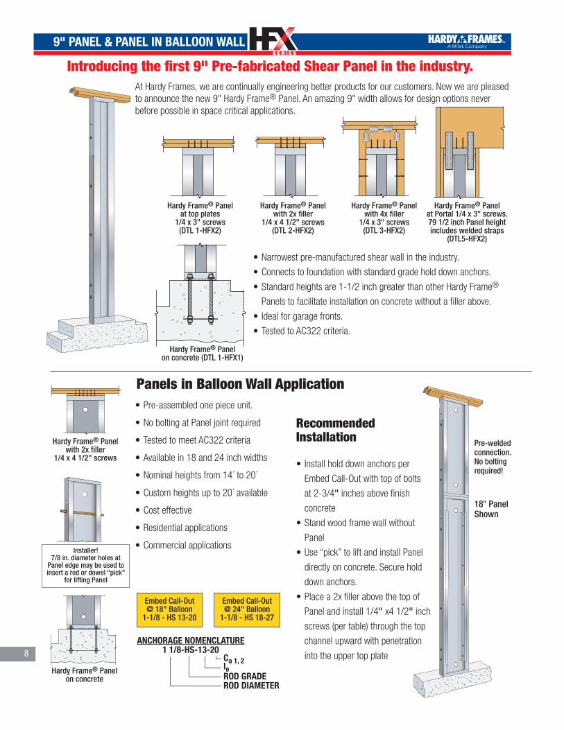
Introducing the first 9" Pre-fabricated Shear Panel in the industry.
HARDY FRAME PANEL BOTTOMON CONCRETE
®
Hardy Frame® Panel on concrete (DTL 1-HFX1)
HARDY FRAME PANEL AT TOP PLATES® HARDY FRAME PANEL WITH 2X FILLER®
Hardy Frame® Panel with 2x filler
1/4 x 4 1/2" screws(DTL 2-HFX2)
Hardy Frame® Panel at top plates
1/4 x 3" screws(DTL 1-HFX2)
HARDY FRAME PANEL WITH 4X FILLER
®
Hardy Frame® Panel with 4x filler
1/4 x 3" screws(DTL 3-HFX2)
HARDY FRAME PANEL AT PORTAL®
Hardy Frame® Panel at Portal 1/4 x 3" screws. 79 1/2 inch Panel height includes welded straps
(DTL5-HFX2)
At Hardy Frames, we are continually engineering better products for our customers. Now we are pleased to announce the new 9" Hardy Frame® Panel. An amazing 9" width allows for design options never before possible in space critical applications.
•Narrowest pre-manufactured shear wall in the industry.
•Connects to foundation with standard grade hold down anchors.
•Standard heights are 1-1/2 inch greater than other Hardy Frame®
Panels to facilitate installation on concrete without a filler above.
• Ideal for garage fronts.
•Tested to AC322 criteria.
•Pre-assembled one piece unit.
•No bolting at Panel joint required
•Tested to meet AC322 criteria
•Available in 18 and 24 inch widths
•Nominal heights from 14´ to 20´
•Custom heights up to 20´ available
•Cost effective
•Residential applications
•Commercial applications
Panels in Balloon Wall Application
Recommended Installation
• Install hold down anchors per
Embed Call-Out with top of bolts
at 2-3/4" inches above finish
concrete
•Stand wood frame wall without
Panel
•Use “pick” to lift and install Panel
directly on concrete. Secure hold
down anchors.
•Place a 2x filler above the top of
Panel and install 1/4" x4 1/2" inch
screws (per table) through the top
channel upward with penetration
into the upper top plate
HARDY FRAME PANEL WITH 2X FILLER®
Hardy Frame® Panel with 2x filler
1/4 x 4 1/2" screws
HARDY FRAME PANEL BOTTOMON CONCRETE
®
Hardy Frame® Panel on concrete
Installer!7/8 in. diameter holes at
Panel edge may be used to insert a rod or dowel “pick”
for lifting Panel
Embed Call-Out @ 18" Balloon
1-1/8 - HS 13-20
18" Panel Shown
Pre-welded connection. No bolting required!
Embed Call-Out @ 24" Balloon
1-1/8 - HS 18-27
Ca 1, 2leROD GRADEROD DIAMETER
ANCHORAGE NOMENCLATURE1 1/8-HS-13-20
9" PANEL & PANEL IN BALLOON WALL
TM
TM
9
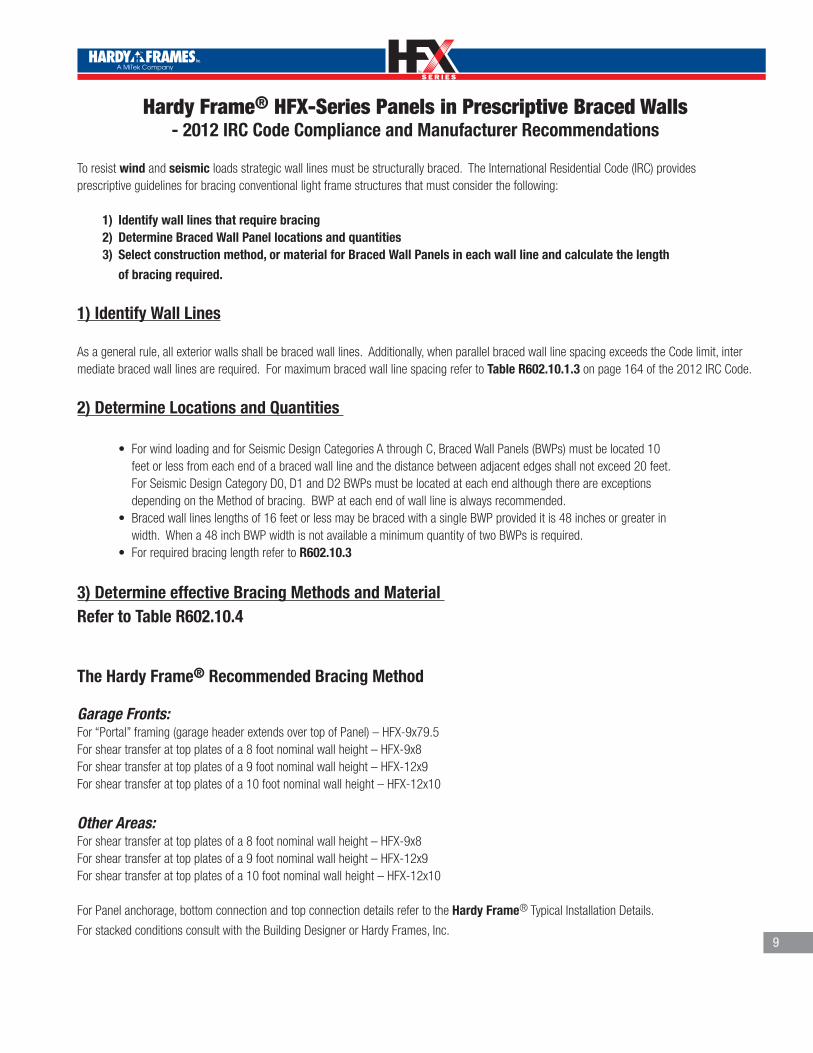
Hardy Frame® HFX-Series Panels in Prescriptive Braced Walls - 2012 IRC Code Compliance and Manufacturer Recommendations
To resist wind and seismic loads strategic wall lines must be structurally braced. The International Residential Code (IRC) provides prescriptive guidelines for bracing conventional light frame structures that must consider the following:
1) Identify wall lines that require bracing 2) Determine Braced Wall Panel locations and quantities 3) Select construction method, or material for Braced Wall Panels in each wall line and calculate the length
of bracing required.
1) Identify Wall Lines
As a general rule, all exterior walls shall be braced wall lines. Additionally, when parallel braced wall line spacing exceeds the Code limit, inter mediate braced wall lines are required. For maximum braced wall line spacing refer to Table R602.10.1.3 on page 164 of the 2012 IRC Code.
2) Determine Locations and Quantities
• ForwindloadingandforSeismicDesignCategoriesAthroughC,BracedWallPanels(BWPs)mustbelocated10 feet or less from each end of a braced wall line and the distance between adjacent edges shall not exceed 20 feet. For Seismic Design Category D0, D1 and D2 BWPs must be located at each end although there are exceptions depending on the Method of bracing. BWP at each end of wall line is always recommended. • Bracedwalllineslengthsof16feetorlessmaybebracedwithasingleBWPprovideditis48inchesorgreaterin width. When a 48 inch BWP width is not available a minimum quantity of two BWPs is required. • ForrequiredbracinglengthrefertoR602.10.3
3) Det ermine effective Bracing Methods and Material Refer to Table R602.10.4
The Hardy Frame® Recommended Bracing Method
Garage Fronts: For “Portal” framing (garage header extends over top of Panel) – HFX-9x79.5For shear transfer at top plates of a 8 foot nominal wall height – HFX-9x8For shear transfer at top plates of a 9 foot nominal wall height – HFX-12x9For shear transfer at top plates of a 10 foot nominal wall height – HFX-12x10
Other Areas: For shear transfer at top plates of a 8 foot nominal wall height – HFX-9x8For shear transfer at top plates of a 9 foot nominal wall height – HFX-12x9For shear transfer at top plates of a 10 foot nominal wall height – HFX-12x10
For Panel anchorage, bottom connection and top connection details refer to the Hardy Frame® Typical Installation Details.
For stacked conditions consult with the Building Designer or Hardy Frames, Inc.

TM
TM
PANELS & BRACE FRAMES
10
HARDY FRAME PANEL BOTTOMON CONCRETE
®
HARDY FRAME BRACE FRAMEBOTTOM ON CONCRETE
®
HARDY FRAME PANEL BOTTOMON DOUBLE NUT
®
HARDY FRAME PANEL BOTTOMON RAISED FLOOR ON CONCRETE
®
Hardy Frame® Panel on concrete
Hardy Frame® Panel on nuts and washers(Requires 5,000 psinon-shrink grout)
Hardy Frame® Panel at raised floor
head out
HARDY FRAME BRACE FRAMEBOTTOM ON DOUBLE NUT
®
HARDY FRAME BRACE FRAMETOP WITH FILLER
®
HARDY FRAME BRACE FRAMETOP WITH TOP PLATE
®
HARDY FRAME PANEL AT TOP PLATES®HARDY FRAME PANEL WITH 2X FILLER®
Hardy Frame® Panel with 2x filler
1/4 x 4 1/2" screws
Hardy Frame® Panel at top plates
1/4 x 3" screwsHARDY FRAME PANEL WITH
4X FILLER
®
Hardy Frame® Panel with 4x filler
1/4 x 3" screwsHARDY FRAME PANEL AT PORTAL
®
Hardy Frame® Panel at Portal
1/4 x 3" screws. 78 inch Panel heights include
welded straps
HARDY FRAME BRACE FRAME4X FILLER
®
HARDY FRAME BRACE FRAMEBOTTOM ON RAISED FLOOR HEAD OUT
®Hardy Frame®
Brace Frame on concrete
Hardy Frame® Brace Frame
on nuts and washers(Requires 5,000 psinon-shrink grout)
Hardy Frame®
Brace Frameat raised floor
head out
Hardy Frame® Brace Frame with 2x filler
1/4 x 4 1/2" screws
Hardy Frame® Brace Frameat top plates
1/4 x 3" screws
Hardy Frame® Brace Framewith 4x filler
1/4 x 3" screws
On Foundations
• Installation on nuts and washers provides for leveling at uneven concrete - open
end box wrench may be used to secure connection from below
•Raised floor head out by passes wood framing to eliminate the effects of
shrinkage and crushing, while providing a direct shear transfer to the foundation
•Raised floor head out requires less material by eliminating the rim, bearing plate
and bottom screws
•The new HFX-Series Brace Frame has relocated hold down bolts to be outside of
the post. Hold down connections are now accessible even when wood or framing
is in contact with the edge of the frame

TM
TM
PANELS & BRACE FRAMES
Table 1.1A Hardy Frame® Installation - on 2500 psi Concrete1,2
Model Number
Net HeightH (in)
HD Rod Dia (in)and Grade 3
AllowableAxial Load 4
Seismic R=6.5 Wind
Allowable In-PlaneShear V 5 (lbs)
Driftat V 5 (in)
Uplift at V 5,6 (lbs)
Allowable In-PlaneShear V 5 (lbs)
Driftat V 5 (in)
Upliftat V 5,6 (lbs)
9" Wide PanelsHFX-9x79.5 79 1/2 1 1/8" STD 2,000 905 0.185 15,460 905 0.185 15,460
HFX-9x8 93 3/4 1 1/8" STD 2,000 765 0.256 15,460 765 0.256 15,46012" Wide Panels
HFX-12x78 78
1 1/8" STD1,000 1,635 0.181 17,425 1,750 0.193 19,5953,500 1,610 0.178 17,005 1,610 0.178 17,0056,500 1,440 0.159 14,325 1,440 0.159 14,325
1 1/8" HS1,000 1,750 0.194 19,595 1,750 0.194 19,5953,500 1,610 0.179 17,005 1,610 0.179 17,0056,500 1,440 0.160 14,325 1,440 0.160 14,325
HFX-12x8 92 1/4
1 1/8" STD1,000 1,385 0.209 17,425 1,480 0.224 19,5953,500 1,365 0.206 17,005 1,365 0.206 17,0056,500 1,220 0.184 14,325 1,220 0.184 14,325
1 1/8" HS1,000 1,480 0.225 19,595 1,480 0.224 19,5953,500 1,365 0.207 17,005 1,365 0.207 17,0056,500 1,220 0.185 14,325 1,220 0.185 14,325
HFX-12x9 104 1/4
1 1/8" STD1,000 1,225 0.232 17,425 1,310 0.248 19,5953,500 1,205 0.229 17,005 1,205 0.229 17,0056,500 1,080 0.205 14,325 1,080 0.205 14,325
1 1/8" HS1,000 1,310 0.250 19,595 1,310 0.250 19,5953,500 1,205 0.230 17,005 1,205 0.230 17,0056,500 1,080 0.206 14,325 1,080 0.206 14,325
HFX-12x10 116 1/4
1 1/8"STD1,000 1,095 0.256 17,425 1,175 0.273 19,5953,500 1,080 0.252 17,005 1,080 0.252 17,0056,500 965 0.225 14,325 965 0.225 14,325
1 1/8" HS1,000 1,175 0.274 19,595 1,175 0.275 19,5953,500 1,080 0.253 17,005 1,080 0.253 17,0056,500 965 0.226 14,325 965 0.226 14,325
18" Wide Panels
HFX-18x78 78
1 1/8"STD1,000
2,580 0.157 15,830 3,250 0.196 21,5853,5006,500
1 1/8" HS1,000 3,900 0.237 28,930 4,380 0.266 38,0153,500 3,840 0.233 28,140 4,195 0.255 33,7006,500 3,740 0.227 26,880 3,885 0.236 28,745
HFX-18x8 92 1/4
1 1/8" STD1,000
2,265 0.188 16,605 2,730 0.227 21,6203,5006,500
1 1/8" HS1,000 3,400 0.284 30,725 3,705 0.310 38,0153,500 3,350 0.280 29,790 3,550 0.297 33,7006,500 3,255 0.272 28,260 3,285 0.275 28,745
HFX-18x9 104 1/4
1 1/8" STD1,000 2,055 0.216 17,130
2,415 0.254 21,6203,500 2,025 0.213 16,8456,500 2,020 0.213 16,755
1 1/8" HS1,000 3,030 0.320 31,190 3,275 0.346 38,0153,500 2,975 0.314 30,030 3,140 0.332 33,7006,500 2,880 0.304 28,260 2,905 0.307 28,745
HFX-18x10 116 1/4
1 1/8" STD1,000 1,855 0.239 17,285
2,170 0.279 21,6203,500 1,845 0.238 17,1556,500 1,835 0.237 17,055
1 1/8" HS1,000 2,720 0.353 31,190 2,940 0.382 21,6203,500 2,670 0.347 30,030 2,815 0.366 33,7006,500 2585 0.336 28,260 2,605 0.339 28,745
HFX-18x11 128 1/4
1 1/8" STD1,000 1,690 0.263 17,430 1,965 0.309 21,6203,5006,500 1,685 0.262 17,310
1 1/8" HS1,000 2,465 0.385 31,190 2,665 0.416 38,0153,500 2,420 0.378 30,030 2,550 0.399 33,7006,500 2,340 0.366 28,260 2,365 0.369 28,745
HFX-18x12 140 1/4
1 1/8" STD1,000
1,545 0.285 17,430 1,780 0.331 21,6203,5006,500
1 1/8" HS1,000 2,255 0.418 31,190 2,435 0.451 38,0153,500 2,210 0.410 30,030 2,335 0.432 33,7006,500 2,140 0.397 28,260 2,160 0.400 28,745
HFX-18x13 152 1/4
1 1/8" STD1,000
1,425 0.306 17,430 1,655 0.356 21,6203,5006,500
1 1/8" HS1,000 2,075 0.449 31,190 2,245 0.485 38,0153,500 2,035 0.441 30,030 2,150 0.465 33,7006,500 1,970 0.427 28,260 1,990 0.431 28,745
11

TM
TM
PANELS & BRACE FRAMES
12
Table 1.1A Hardy Frame® Installation - on 2500 psi Concrete1,2
Model Number
Net HeightH (in)
HD Rod Dia (in)and Grade 3
AllowableAxial Load 4
Seismic R=6.5 Wind
Allowable In-PlaneShear V 5 (lbs)
Driftat V 5 (in)
Uplift at V 5,6 (lbs)
Allowable In-PlaneShear V 5 (lbs)
Driftat V 5 (in)
Upliftat V 5,6 (lbs)
18" Wide Panels Balloon WallHFX-18x14 164 1/4
1 1/8" HS
4,000 1,380 0.642 18,473 1,960 0.913 32,447HFX-18x15 176 1/4 3,500 1,310 0.701 18,937 1,830 0.979 32,584HFX-18x16 188 1/4 3,000 1,250 0.760 19,433 1,715 1.046 32,654HFX-18x17 200 1/4 2,500 1,195 0.824 19,888 1,615 1.113 32,781HFX-18x18 212 1/4 2,000 1,150 0.887 20,455 1,530 1.179 33,092HFX-18x19 224 1/4 2,000 1,105 0.953 20,885 1,450 1.244 33,191HFX-18x20 236 1/4 2,000 1,070 1.020 21,489 1,220 1.166 26,317
24" Wide Panels
HFX-24x78 78
1 1/8" STD1,000
3,490 0.112 14,365 4,430 0.142 19,0203,5006,500
1 1/8" HS1,000 5,600 0.182 25,565 6,950 0.225 34,9753,500 5,610 0.182 25,645 6,900 0.224 34,5856,500 5,605 0.182 25,600 6,815 0.221 33,925
HFX-24x8 92 1/4
1 1/8" STD1,000
3,080 0.136 15,085 3,935 0.174 20,1803,5006,500
1 1/8" HS1,000
4,950 0.220 27,1706,125 0.273 37,490
3,500 6,080 0.271 37,0256,500 6,005 0.268 36,245
HFX-24x9 104 1/4
1 1/8" STD1,000
2,800 0.156 15,5603,595 0.201 20,985
3,500 3,590 0.201 20,9856,500
1 1/8" HS1,000
4,510 0.254 28,3005,570 0.313 39,335
3,500 5,530 0.311 38,8056,500 5,455 0.307 37,925
HFX-24x10 116 1/4
1 1/8" STD1,000 2,580 0.177 16,055 3,305 0.227 21,6203,500 3,275 0.225 21,4356,500 2,540 0.174 15,765 3,265 0.224 21,345
1 1/8" HS1,000
4,145 0.287 29,2705,035 0.348 39,865
3,500 4,985 0.345 39,1806,500 4,905 0.339 38,055
HFX-24x11 128 1/4
1 1/8"STD1,000 2,390 0.198 16,480 2,980 0.246 21,6203,5006,500 2,350 0.194 16,140 3,010 0.248 21,620
1 1/8" HS1,000
3,730 0.308 28,9854,560 0.377 39,865
3,500 4,520 0.374 39,1806,500 4,445 0.368 38,055
HFX-24x12 140 1/4
1 1/8" STD1,000 2,230 0.218 16,855
2,720 0.267 21,6203,500 2,195 0.215 16,5556,500 2,185 0.214 16,455
1 1/8" HS1,000
3,410 0.334 28,9754,170 0.409 39,865
3,500 4,130 0.405 39,1806,500 4,065 0.399 38,055
HFX-24x13 152 1/4
1 1/8" STD1,000 2,085 0.240 17,180
2,505 0.287 21,6203,500 2,050 0.235 16,8206,500 2,040 0.234 16,720
1 1/8" HS1,000
3,140 0.360 28,9603,845 0.441 39,865
3,500 3,805 0.437 39,1806,500 3,745 0.429 38,055
24" Wide Panels Balloon WallHFX-24x14 164 1/4
1 1/8" HS
4,000 2,090 0.527 18,855 3,190 0.805 33,157HFX-24x15 176 1/4 3,500 1,960 0.597 19,000 2,830 0.859 30,788HFX-24x16 188 1/4 3,000 1,825 0.625 18,874 2,670 0.913 31,139HFX-24x17 200 1/4 2,500 1,695 0.660 18,600 2,485 0.967 30,683HFX-24x18 212 1/4 2,000 1,595 0.697 18,541 2,335 1.020 30,503HFX-24x19 224 1/4 2,000 1,515 0.734 18,620 2,220 1.072 30,702HFX-24x20 236 1/4 2,000 1,460 0.770 18,965 2,130 1.124 31,192
32" Wide Brace Frames
HFX-32x8 92 1/4
7/8" STD1,000 2,225 0.130 8,375 2,825 0.165 10,6303,500 2,160 0.126 8,130 2,160 0.126 8,1306,500 1,360 0.080 5,130 1,360 0.080 5,130
7/8" HS1,000 3,000 0.176 11,295 3,000 0.176 11,2953,500 2,335 0.137 8,795 2,335 0.137 8,7956,500 1,540 0.090 5,795 1,540 0.090 5,795

TM
TM
PANELS & BRACE FRAMES
Table 1.1A Hardy Frame® Installation - on 2500 psi Concrete1,2
Model Number
Net HeightH (in)
HD Rod Dia (in)
and Grade 3
AllowableAxial Load 4
Seismic R=6.5 Wind
Allowable In-PlaneShear V 5
(lbs)
Driftat V 5 (in)
Uplift at V 5,6 (lbs)
Allowable In-PlaneShear V 5
(lbs)
Driftat V 5 (in)
Upliftat V 5,6
(lbs)
32" Wide Brace Frames
HFX-32x9 104 1/4
7/8" STD1,000 2,050 0.169 8,715 2,500 0.207 10,6303,500 1,910 0.158 8,130 1,910 0.158 8,1306,500 1,205 0.100 5,130 1,205 0.100 5,130
7/8" HS1,000 2,655 0.220 11,295 2,655 0.220 11,2953,500 2,065 0.171 8,795 2,065 0.171 8,7956,500 1,360 0.113 5,795 1,360 0.113 5,795
HFX-32x10 116 1/4
7/8" STD1,000 1,900 0.215 9,005 2,240 0.254 10,6303,500 1,715 0.194 8,130 1,715 0.194 8,1306,500 1,080 0.122 5,130 1,080 0.122 5,130
7/8" HS1,000 2,380 0.270 11,295 2,380 0.269 11,2953,500 1,855 0.210 8,795 1,855 0.210 8,7956,500 1,220 0.138 5,795 1,220 0.138 5,795
HFX-32x11 128 1/4
7/8" STD1,000 1,770 0.266 9,255 2,030 0.306 10,6303,500 1,555 0.234 8,130 1,555 0.234 8,1306,500 980 0.147 5,130 980 0.148 5,130
7/8" HS1,000 2,160 0.325 11,295 2,160 0.325 11,2953,500 1,680 0.253 8,795 1,680 0.253 8,7956,500 1,105 0.167 5,795 1,105 0.167 5,795
HFX-32x12 140 1/4
7/8" STD1,000 1,655 0.323 9,470 1,855 0.364 10,6303,500 1,420 0.278 8,130 1,420 0.278 8,1306,500 895 0.175 5,130 895 0.175 5,130
7/8" HS1,000 1,975 0.386 11,295 1,975 0.386 11,2953,500 1,535 0.300 8,795 1,535 0.300 8,7956,500 1,010 0.198 5,795 1,010 0.198 5,795
HFX-32x13 152 1/4
7/8" STD1,000 1,555 0.386 9,665 1,710 0.425 10,6303,500 1,310 0.325 8,130 1,310 0.325 8,1306,500 825 0.205 5,130 825 0.205 5,130
7/8" HS1,000 1,820 0.452 11,295 1,820 0.452 11,2953,500 1,415 0.352 8,795 1,415 0.352 8,7956,500 935 0.232 5,795 935 0.232 5,795
44" Wide Brace Frames
HFX-44x8 92 1/4
7/8" STD1,000 2,810 0.090 7,250 3,745 0.119 9,6653,500 3,240 0.103 8,3656,500 2,080 0.066 5,365 2,080 0.066 5,365
7/8" HS1,000 4,510 0.144 11,645 4,510 0.144 11,6453,500 3,545 0.113 9,145 3,545 0.113 9,1456,500 2,380 0.076 6,145 2,380 0.076 6,145
HFX-44x9 104 1/4
7/8" STD1,000 2,615 0.115 7,625 3,485 0.154 10,1653,500 2,615 0.115 7,625 2,870 0.127 83656,500 1,840 0.081 5,365 1,840 0.081 5,365
7/8" HS1,000 3,995 0.177 11,645 3,995 0.177 116453,500 3,135 0.139 9,145 3,135 0.139 9,1456,500 2,105 0.093 6,145 2,105 0.093 6,145
HFX-44x10 116 1/4
7/8" STD1,000 2,445 0.147 7,950 3,260 0.195 10,6003,500 2,445 0.147 7,950 2,575 0.154 8,3656,500 1,650 0.099 5,365 1,650 0.099 5,365
7/8"HS1,000 3,580 0.214 11,645 3,580 0.214 11,6453,500 2,810 0.168 9,145 2,810 0.168 9,1456,500 1,890 0.113 6,145 1,890 0.113 6,145
HFX-44x11 128 1/4
7/8" STD1,000 2,295 0.182 8,240 3,030 0.239 10,8653,500 2,295 0.182 8,240 2,330 0.184 8,3656,500 1,495 0.118 5,365 1,495 0.118 5,365
7/8" HS1,000 3,245 0.255 11,645 3,245 0.256 11,6453,500 2,550 0.201 9,145 2,550 0.201 9,1456,500 1,715 0.135 6,145 1,715 0.135 6,145
HFX-44x12 140 1/4
7/8" STD1,000 2,165 0.219 8,490 2,770 0.281 10,8653,500 2,135 0.216 8,365 2,135 0.216 8,3656,500 1,370 0.139 5,365 1,370 0.139 5,365
7/8" HS1,000 2,970 0.301 11,645 2,970 0.302 11,6453,500 2,330 0.237 9,145 2,330 0.237 9,1456,500 1,565 0.159 6,145 1,565 0.159 6,145
HFX-44x13 152 1/4
7/8" STD1,000 2,045 0.263 8,715 2,550 0.327 10,8653,500 1,965 0.252 8,365 1,965 0.252 8,3656,500 1,260 0.162 5,365 1,260 0.162 5,365
7/8" HS1,000 2,735 0.351 11,645 2,735 0.351 11,6453,500 2,145 0.275 9,145 2,145 0.275 9,1456,500 1,445 0.185 6,145 1,445 0.185 6,145
13
REMINDER:SPECIFY ANCHORAGE ON
FOUNDATION PLAN.SEE ANCHORAGE DETAILS.
Notes1. The values in this table are Allowable
Stress Design (ASD) excluding a 1.33 stress increase and pertain to instal-lation on 2500 psi concrete or nut & washer with 5,000 psi minimum non-shrink grout.
2. For installation on a nut & washer with grout pad, table values must be multiplied by 0.80.
3. STD indicates Rods complying with ASTM F 1554 Grade 36. HS rods in-clude, but are not limited to ASTM F 1554 Grade 105, ASTM A 193 Grade B7 or ASTM A 354 Grade BD
4. The additional vertical axial loads are concurrent with the allowable shear load. For Panels the axial load must be applied within the middle 1/3 of the Panel width or be uniformly distributed across the entire Panel width. For Brace Frame the axial load is acting and along the center-line of the post.
5. Allowable shear, drift and uplift values may be linearly interpolated for intermediate height or axial loads.
The Uplift values listed assume no resisting axial load. To determine anchor tension loads in Panels at design shear values and including the effect of axial loads, refer to the Equation for Tension Uplift in the Examples Section of this catalog. For Brace Frames the anchor tension load equals uplift minus P, where P is the axial load in the Post. For SI: 1 inch = 25.4 mm, 1 foot = 304.8 mm, 1 lb = 4.45 N, 1 psi 6.89 kPa.
NOMINAL HEIGHTACTUAL WIDTHPRODUCT SERIES
PANEL NOMENCLATUREHFX-18 x 9
Ca 1, 2leROD GRADEROD DIAMETER
ANCHORAGE NOMENCLATURE1 1/8-STD-14-20
TM
TM
PANELS & BRACE FRAMES
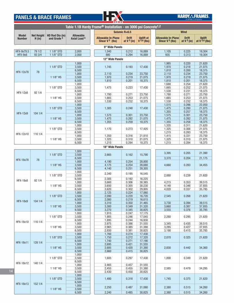
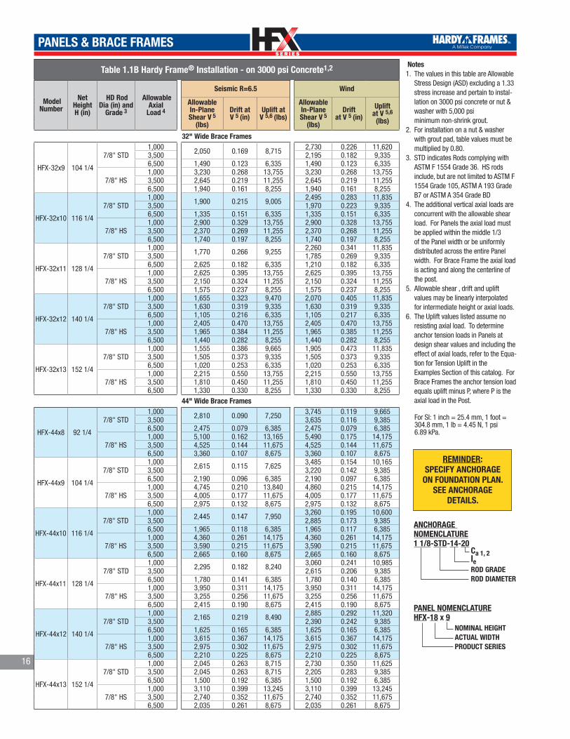
Table 1.1B Hardy Frame® Installation - on 3000 psi Concrete1,2
Model Number
Net HeightH (in)
HD Rod Dia (in)and Grade 3
AllowableAxial Load 4
Seismic R=6.5 Wind
Allowable In-PlaneShear V 5 (lbs)
Driftat V 5 (in)
Uplift at V 5,6 (lbs)
Allowable In-PlaneShear V 5 (lbs)
Driftat V 5 (in)
Upliftat V 5,6 (lbs)
9” Wide PanelsHFX-9x79.5 79 1/2 1 1/8” STD 2,000 1,040 0.212 16,889 1,105 0.225 19,304
HFX-9x8 93 3/4 1 1/8” STD 2,000 880 0.294 16,889 935 0.313 19,30412” Wide Panels
HFX-12x78 78
1 1/8” STD1,000
1,745 0.193 17,4301,985 0.220 21,620
3,500 1,970 0.218 21,0756,500 1,810 0.200 18,375
1 1/8” HS1,000 2,110 0.234 23,750 2,110 0.234 23,7503,500 1,970 0.219 21,075 1,970 0.219 21,0756,500 1,810 0.201 18,375 1,810 0.201 18,375
HFX-12x8 92 1/4
1 1/8” STD1,000
1,475 0.223 17,4301,680 0.254 21,620
3,500 1,665 0.252 21,0756,500 1,530 0.231 18,375
1 1/8” HS1,000 1,780 0.271 23,750 1,780 0.271 23,7503,500 1,665 0.253 21,075 1,665 0.253 21,0756,500 1,530 0.232 18,375 1,530 0.232 18,375
HFX-12x9 104 1/4
1 1/8” STD1,000
1,305 0.248 17,4301,515 0.286 22,050
3,500 1,475 0.280 21,0756,500 1,355 0.257 18,375
1 1/8” HS1,000 1,575 0.301 23,750 1,575 0.301 23,7503,500 1,475 0.282 21,075 1,475 0.282 21,0756,500 1,355 0.259 18,375 1,355 0.258 18,375
HFX-12x10 116 1/4
1 1/8” STD1,000
1,170 0.273 17,4251,335 0.311 21,620
3,500 1,325 0.308 21,0756,500 1,215 0.283 18,375
1 1/8” HS1,000 1,350 0.316 21,810 1,415 0.331 23,7503,500 1,325 0.310 21,075 1,325 0.310 21,0756,500 1,215 0.284 18,375 1,215 0.284 18,375
18” Wide Panels
HFX-18x78 78
1 1/8” STD1,000
2,665 0.162 15,790 3,395 0.205 21,3903,5006,500 3,370 0.204 21,175
1 1/8” HS1,000 4,190 0.254 28,800
4,660 0.283 34,4553,500 4,175 0.254 28,6806,500 4,140 0.251 28,305
HFX-18x8 92 1/4
1 1/8” STD1,000 2,340 0.195 16,545 2,880 0.239 21,6203,5006,500 2,305 0.192 16,225
1 1/8” HS1,000 3,660 0.306 30,365 4,215 0.353 39,5153,500 3,650 0.305 30,230 4,140 0.346 37,9356,500 3,620 0.302 29,805 4,020 0.337 35,785
HFX-18x9 104 1/4
1 1/8” STD1,000 2,125 0.224 17,060
2,545 0.268 21,6203,500 2,090 0.220 16,7206,500 2,080 0.219 16,615
1 1/8” HS1,000 3,310 0.350 31,465 3,730 0.394 39,5153,500 3,300 0.349 31,320 3,660 0.387 37,9356,500 3,270 0.345 30,825 3,555 0.376 35,785
HFX-18x10 116 1/4
1 1/8” STD1,000 1,915 0.247 17,175
2,280 0.295 21,6203,500 1,905 0.246 17,0456,500 1,895 0.244 16,930
1 1/8” HS1,000 2,975 0.386 31,555 3,345 0.435 39,5153,500 2,965 0.385 31,380 3,285 0.427 37,9356,500 2,930 0.381 30,825 3,190 0.415 35,785
HFX-18x11 128 1/4
1 1/8” STD1,000 1,760 0.274 17,430
2,070 0.325 21,6203,500 1,750 0.272 17,3206,500 1,740 0.271 17,190
1 1/8” HS1,000 2,695 0.421 31,555
2,830 0.442 34,3603,500 2,685 0.420 31,3806,500 2,660 0.415 30,825
HFX-18x12 140 1/4
1 1/8” STD1,000
1,605 0.297 17,430 1,890 0.349 21,6203,5006,500
1 1/8” HS1,000 2,465 0.457 31,555
2,585 0.479 34,2953,500 2,455 0.455 31,3806,500 2,430 0.450 30,825
HFX-18x13 152 1/4
1 1/8” STD1,000
1,480 0.318 17,430 1,745 0.375 21,6203,5006,500
1 1/8” HS1,000 2,250 0.487 31,080 2,380 0.515 34,2603,5006,500 2,240 0.485 30,825 2,380 0.515 34,260
14
TM
TM
PANELS & BRACE FRAMES
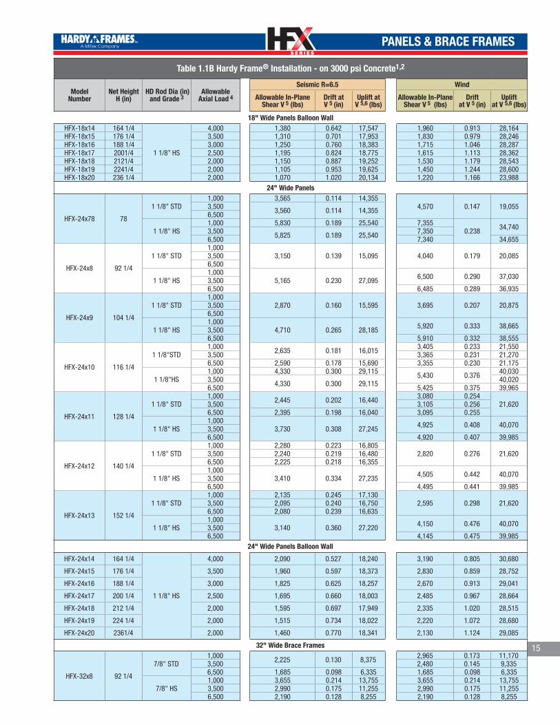
Table 1.1B Hardy Frame® Installation - on 3000 psi Concrete1,2
Model Number
Net HeightH (in)
HD Rod Dia (in)and Grade 3
AllowableAxial Load 4
Seismic R=6.5 Wind
Allowable In-PlaneShear V 5 (lbs)
Drift at V 5 (in)
Uplift at V 5,6 (lbs)
Allowable In-PlaneShear V 5 (lbs)
Driftat V 5 (in)
Upliftat V 5,6 (lbs)
18" Wide Panels Balloon WallHFX-18x14 164 1/4
1 1/8” HS
4,000 1,380 0.642 17,547 1,960 0.913 28,164HFX-18x15 176 1/4 3,500 1,310 0.701 17,953 1,830 0.979 28,246HFX-18x16 188 1/4 3,000 1,250 0.760 18,383 1,715 1.046 28,287HFX-18x17 2001/4 2,500 1,195 0.824 18,775 1,615 1.113 28,362HFX-18x18 2121/4 2,000 1,150 0.887 19,252 1,530 1.179 28,543HFX-18x19 2241/4 2,000 1,105 0.953 19,625 1,450 1.244 28,600HFX-18x20 236 1/4 2,000 1,070 1.020 20,134 1,220 1.166 23,988
24" Wide Panels
HFX-24x78 78
1 1/8" STD1,000 3,565 0.114 14,355
4,570 0.147 19,0553,500 3,560 0.114 14,3556,500
1 1/8" HS1,000 5,830 0.189 25,540 7,355
0.238 34,7403,500 5,825 0.189 25,540 7,3506,500 7,340 34,655
HFX-24x8 92 1/4
1 1/8" STD1,000
3,150 0.139 15,095 4,040 0.179 20,0853,5006,500
1 1/8" HS1,000
5,165 0.230 27,095 6,500 0.290 37,0303,5006,500 6,485 0.289 36,935
HFX-24x9 104 1/4
1 1/8" STD1,000
2,870 0.160 15,595 3,695 0.207 20,8753,5006,500
1 1/8" HS1,000
4,710 0.265 28,185 5,920 0.333 38,6653,5006,500 5,910 0.332 38,555
HFX-24x10 116 1/4
1 1/8"STD1,000 2,635 0.181 16,015 3,405 0.233 21,5503,500 3,365 0.231 21,2706,500 2,590 0.178 15,690 3,355 0.230 21,175
1 1/8"HS1,000 4,330 0.300 29,115 5,430 0.376 40,0303,500 4,330 0.300 29,115 40,0206,500 5,425 0.375 39,965
HFX-24x11 128 1/4
1 1/8" STD1,000 2,445 0.202 16,440 3,080 0.254
21,6203,500 3,105 0.2566,500 2,395 0.198 16,040 3,095 0.255
1 1/8" HS1,000
3,730 0.308 27,245 4,925 0.408 40,0703,5006,500 4,920 0.407 39,985
HFX-24x12 140 1/4
1 1/8" STD1,000 2,280 0.223 16,805
2,820 0.276 21,6203,500 2,240 0.219 16,4806,500 2,225 0.218 16,355
1 1/8" HS1,000
3,410 0.334 27,235 4,505 0.442 40,0703,5006,500 4,495 0.441 39,985
HFX-24x13 152 1/4
1 1/8" STD1,000 2,135 0.245 17,130
2,595 0.298 21,6203,500 2,095 0.240 16,7506,500 2,080 0.239 16,635
1 1/8" HS1,000
3,140 0.360 27,220 4,150 0.476 40,0703,5006,500 4,145 0.475 39,985
24" Wide Panels Balloon Wall
HFX-24x14 164 1/4
1 1/8" HS
4,000 2,090 0.527 18,240 3,190 0.805 30,680
HFX-24x15 176 1/4 3,500 1,960 0.597 18,373 2,830 0.859 28,752
HFX-24x16 188 1/4 3,000 1,825 0.625 18,257 2,670 0.913 29,041
HFX-24x17 200 1/4 2,500 1,695 0.660 18,003 2,485 0.967 28,664
HFX-24x18 212 1/4 2,000 1,595 0.697 17,949 2,335 1.020 28,515
HFX-24x19 224 1/4 2,000 1,515 0.734 18,022 2,220 1.072 28,680
HFX-24x20 2361/4 2,000 1,460 0.770 18,341 2,130 1.124 29,085
32" Wide Brace Frames
HFX-32x8 92 1/4
7/8" STD1,000 2,225 0.130 8,375 2,965 0.173 11,1703,500 2,480 0.145 9,3356,500 1,685 0.098 6,335 1,685 0.098 6,335
7/8" HS1,000 3,655 0.214 13,755 3,655 0.214 13,7553,500 2,990 0.175 11,255 2,990 0.175 11,2556,500 2,190 0.128 8,255 2,190 0.128 8,255
15
TM
TM
PANELS & BRACE FRAMES
Table 1.1B Hardy Frame® Installation - on 3000 psi Concrete1,2
Model Number
Net HeightH (in)
HD Rod Dia (in) and
Grade 3
AllowableAxial
Load 4
Seismic R=6.5 Wind
AllowableIn-PlaneShear V 5
(lbs)
Drift at V 5 (in)
Uplift at V 5,6 (lbs)
Allowable In-PlaneShear V 5
(lbs)
Driftat V 5 (in)
Upliftat V 5,6
(lbs)
32" Wide Brace Frames
HFX-32x9 104 1/4
7/8" STD1,000 2,050 0.169 8,715 2,730 0.226 11,6203,500 2,195 0.182 9,3356,500 1,490 0.123 6,335 1,490 0.123 6,335
7/8" HS1,000 3,230 0.268 13,755 3,230 0.268 13,7553,500 2,645 0.219 11,255 2,645 0.219 11,2556,500 1,940 0.161 8,255 1,940 0.161 8,255
HFX-32x10 116 1/4
7/8" STD1,000 1,900 0.215 9,005 2,495 0.283 11,8353,500 1,970 0.223 9,3356,500 1,335 0.151 6,335 1,335 0.151 6,335
7/8" HS1,000 2,900 0.329 13,755 2,900 0.328 13,7553,500 2,370 0.269 11,255 2,370 0.268 11,2556,500 1,740 0.197 8,255 1,740 0.197 8,255
HFX-32x11 128 1/4
7/8" STD1,000 1,770 0.266 9,255 2,260 0.341 11,8353,500 1,785 0.269 9,3356,500 2,625 0.182 6,335 1,210 0.182 6,335
7/8" HS1,000 2,625 0.395 13,755 2,625 0.395 13,7553,500 2,150 0.324 11,255 2,150 0.324 11,2556,500 1,575 0.237 8,255 1,575 0.237 8,255
HFX-32x12 140 1/4
7/8" STD1,000 1,655 0.323 9,470 2,070 0.405 11,8353,500 1,630 0.319 9,335 1,630 0.319 9,3356,500 1,105 0.216 6,335 1,105 0.217 6,335
7/8" HS1,000 2,405 0.470 13,755 2,405 0.470 13,7553,500 1,965 0.384 11,255 1,965 0.385 11,2556,500 1,440 0.282 8,255 1,440 0.282 8,255
HFX-32x13 152 1/4
7/8" STD1,000 1,555 0.386 9,665 1,905 0.473 11,8353,500 1,505 0.373 9,335 1,505 0.373 9,3356,500 1,020 0.253 6,335 1,020 0.253 6,335
7/8" HS1,000 2,215 0.550 13,755 2,215 0.550 13,7553,500 1,810 0.450 11,255 1,810 0.450 11,2556,500 1,330 0.330 8,255 1,330 0.330 8,255
44" Wide Brace Frames
HFX-44x8 92 1/4
7/8" STD1,000 2,810 0.090 7,250 3,745 0.119 9,6653,500 3,635 0.116 9,3856,500 2,475 0.079 6,385 2,475 0.079 6,385
7/8" HS1,000 5,100 0.162 13,165 5,490 0.175 14,1753,500 4,525 0.144 11,675 4,525 0.144 11,6756,500 3,360 0.107 8,675 3,360 0.107 8,675
HFX-44x9 104 1/4
7/8" STD1,000 2,615 0.115 7,625 3,485 0.154 10,1653,500 3,220 0.142 9,3856,500 2,190 0.096 6,385 2,190 0.097 6,385
7/8" HS1,000 4,745 0.210 13,840 4,860 0.215 14,1753,500 4,005 0.177 11,675 4,005 0.177 11,6756,500 2,975 0.132 8,675 2,975 0.132 8,675
HFX-44x10 116 1/4
7/8" STD1,000 2,445 0.147 7,950 3,260 0.195 10,6003,500 2,885 0.173 9,3856,500 1,965 0.118 6,385 1,965 0.117 6,385
7/8" HS1,000 4,360 0.261 14,175 4,360 0.261 14,1753,500 3,590 0.215 11,675 3,590 0.215 11,6756,500 2,665 0.160 8,675 2,665 0.160 8,675
HFX-44x11 128 1/4
7/8" STD1,000 2,295 0.182 8,240 3,060 0.241 10,9853,500 2,615 0.206 9,3856,500 1,780 0.141 6,385 1,780 0.140 6,385
7/8" HS1,000 3,950 0.311 14,175 3,950 0.311 14,1753,500 3,255 0.256 11,675 3,255 0.256 11,6756,500 2,415 0.190 8,675 2,415 0.190 8,675
HFX-44x12 140 1/4
7/8" STD1,000 2,165 0.219 8,490 2,885 0.292 11,3203,500 2,390 0.242 9,3856,500 1,625 0.165 6,385 1,625 0.165 6,385
7/8" HS1,000 3,615 0.367 14,175 3,615 0.367 14,1753,500 2,975 0.302 11,675 2,975 0.302 11,6756,500 2,210 0.225 8,675 2,210 0.225 8,675
HFX-44x13 152 1/4
7/8" STD1,000 2,045 0.263 8,715 2,730 0.350 11,6253,500 2,045 0.263 8,715 2,205 0.283 9,3856,500 1,500 0.192 6,385 1,500 0.192 6,385
7/8" HS1,000 3,110 0.399 13,245 3,110 0.399 13,2453,500 2,740 0.352 11,675 2,740 0.352 11,6756,500 2,035 0.261 8,675 2,035 0.261 8,675
Notes1. The values in this table are Allowable
Stress Design (ASD) excluding a 1.33 stress increase and pertain to instal-lation on 3000 psi concrete or nut & washer with 5,000 psi minimum non-shrink grout.
2. For installation on a nut & washer with grout pad, table values must be multiplied by 0.80.
3. STD indicates Rods complying with ASTM F 1554 Grade 36. HS rods include, but are not limited to ASTM F 1554 Grade 105, ASTM A 193 Grade B7 or ASTM A 354 Grade BD
4. The additional vertical axial loads are concurrent with the allowable shear load. For Panels the axial load must be applied within the middle 1/3 of the Panel width or be uniformly distributed across the entire Panel width. For Brace Frame the axial load is acting and along the centerline of the post.
5. Allowable shear , drift and uplift values may be linearly interpolated for intermediate height or axial loads.
6. The Uplift values listed assume no resisting axial load. To determine anchor tension loads in Panels at design shear values and including the effect of axial loads, refer to the Equa-tion for Tension Uplift in the Examples Section of this catalog. For Brace Frames the anchor tension load equals uplift minus P, where P is the axial load in the Post.
For SI: 1 inch = 25.4 mm, 1 foot = 304.8 mm, 1 lb = 4.45 N, 1 psi 6.89 kPa.
16
REMINDER:SPECIFY ANCHORAGE
ON FOUNDATION PLAN.SEE ANCHORAGE
DETAILS.
NOMINAL HEIGHTACTUAL WIDTHPRODUCT SERIES
PANEL NOMENCLATUREHFX-18 x 9
Ca 1, 2leROD GRADEROD DIAMETER
ANCHORAGE NOMENCLATURE1 1/8-STD-14-20
TM
TM
PANELS & BRACE FRAMES
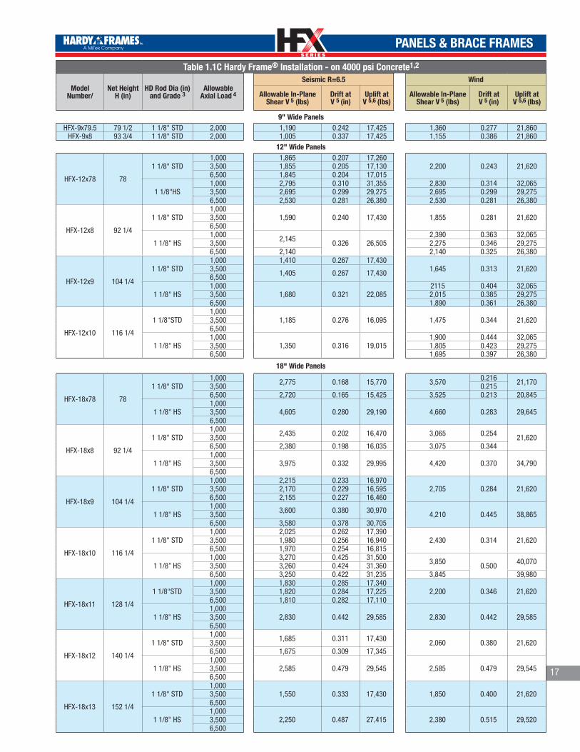
Table 1.1C Hardy Frame® Installation - on 4000 psi Concrete1,2
Model Number/
Net HeightH (in)
HD Rod Dia (in)and Grade 3
AllowableAxial Load 4
Seismic R=6.5 Wind
Allowable In-PlaneShear V 5 (lbs)
Drift atV 5 (in)
Uplift at V 5,6 (lbs)
Allowable In-PlaneShear V 5 (lbs)
Drift at V 5 (in)
Uplift at V 5,6 (lbs)
9" Wide PanelsHFX-9x79.5 79 1/2 1 1/8" STD 2,000 1,190 0.242 17,425 1,360 0.277 21,860
HFX-9x8 93 3/4 1 1/8" STD 2,000 1,005 0.337 17,425 1,155 0.386 21,86012" Wide Panels
HFX-12x78 78
1 1/8" STD1,000 1,865 0.207 17,260
2,200 0.243 21,6203,500 1,855 0.205 17,1306,500 1,845 0.204 17,015
1 1/8"HS1,000 2,795 0.310 31,355 2,830 0.314 32,0653,500 2,695 0.299 29,275 2,695 0.299 29,2756,500 2,530 0.281 26,380 2,530 0.281 26,380
HFX-12x8 92 1/4
1 1/8" STD1,000
1,590 0.240 17,430 1,855 0.281 21,6203,5006,500
1 1/8" HS1,000 2,145 0.326 26,505
2,390 0.363 32,0653,500 2,275 0.346 29,2756,500 2,140 2,140 0.325 26,380
HFX-12x9 104 1/4
1 1/8" STD1,000 1,410 0.267 17,430
1,645 0.313 21,6203,500 1,405 0.267 17,4306,500
1 1/8" HS1,000
1,680 0.321 22,0852115 0.404 32,065
3,500 2,015 0.385 29,2756,500 1,890 0.361 26,380
HFX-12x10 116 1/4
1 1/8"STD1,000
1,185 0.276 16,095 1,475 0.344 21,6203,5006,500
1 1/8" HS1,000
1,350 0.316 19,0151,900 0.444 32,065
3,500 1,805 0.423 29,2756,500 1,695 0.397 26,380
18" Wide Panels
HFX-18x78 78
1 1/8" STD1,000 2,775 0.168 15,770 3,570 0.216 21,1703,500 0.2156,500 2,720 0.165 15,425 3,525 0.213 20,845
1 1/8" HS1,000
4,605 0.280 29,190 4,660 0.283 29,6453,5006,500
HFX-18x8 92 1/4
1 1/8" STD1,000 2,435 0.202 16,470 3,065 0.254 21,6203,5006,500 2,380 0.198 16,035 3,075 0.344
1 1/8" HS1,000
3,975 0.332 29,995 4,420 0.370 34,7903,5006,500
HFX-18x9 104 1/4
1 1/8" STD1,000 2,215 0.233 16,970
2,705 0.284 21,6203,500 2,170 0.229 16,5956,500 2,155 0.227 16,460
1 1/8" HS1,000 3,600 0.380 30,970 4,210 0.445 38,8653,5006,500 3,580 0.378 30,705
HFX-18x10 116 1/4
1 1/8" STD1,000 2,025 0.262 17,390
2,430 0.314 21,6203,500 1,980 0.256 16,9406,500 1,970 0.254 16,815
1 1/8” HS1,000 3,270 0.425 31,500 3,850 0.500 40,0703,500 3,260 0.424 31,3606,500 3,250 0.422 31,235 3,845 39,980
HFX-18x11 128 1/4
1 1/8"STD1,000 1,830 0.285 17,340
2,200 0.346 21,6203,500 1,820 0.284 17,2256,500 1,810 0.282 17,110
1 1/8" HS1,000
2,830 0.442 29,585 2,830 0.442 29,5853,5006,500
HFX-18x12 140 1/4
1 1/8" STD1,000 1,685 0.311 17,430 2,060 0.380 21,6203,5006,500 1,675 0.309 17,345
1 1/8" HS1,000
2,585 0.479 29,545 2,585 0.479 29,5453,5006,500
HFX-18x13 152 1/4
1 1/8" STD1,000
1,550 0.333 17,430 1,850 0.400 21,6203,5006,500
1 1/8" HS1,000
2,250 0.487 27,415 2,380 0.515 29,5203,5006,500
17
TM
TM
PANELS & BRACE FRAMES
18
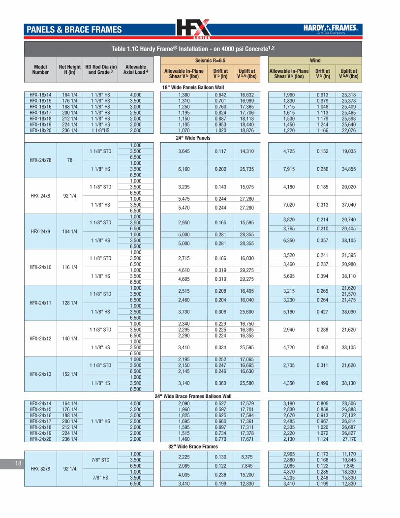
Table 1.1C Hardy Frame® Installation - on 4000 psi Concrete1,2
Model Number
Net HeightH (in)
HD Rod Dia (in)and Grade 3
AllowableAxial Load 4
Seismic R=6.5 Wind
Allowable In-PlaneShear V 5 (lbs)
Drift atV 5 (in)
Uplift at V 5,6 (lbs)
Allowable In-PlaneShear V 5 (lbs)
Drift at V 5 (in)
Uplift at V 5,6 (lbs)
18" Wide Panels Balloon WallHFX-18x14 164 1/4 1 1/8" HS 4,000 1,380 0.642 16,632 1,960 0.913 25,318HFX-18x15 176 1/4 1 1/8" HS 3,500 1,310 0.701 16,989 1,830 0.979 25,378HFX-18x16 188 1/4 1 1/8" HS 3,000 1,250 0.760 17,365 1,715 1.046 25,409HFX-18x17 200 1/4 1 1/8" HS 2,500 1,195 0.824 17,706 1,615 1.113 25,465HFX-18x18 212 1/4 1 1/8" HS 2,000 1,150 0.887 18,118 1,530 1.179 25,598HFX-18x19 224 1/4 1 1/8" HS 2,000 1,105 0.953 18,440 1,450 1.244 25,640HFX-18x20 236 1/4 1 1/8"HS 2,000 1,070 1.020 18,876 1,220 1.166 22,076
24" Wide Panels
HFX-24x78 78
1 1/8" STD1,000
3,645 0.117 14,310 4,725 0.152 19,0353,5006,500
1 1/8" HS1,000
6,160 0.200 25,735 7,915 0.256 34,8553,5006,500
HFX-24x8 92 1/4
1 1/8" STD1,000
3,235 0.143 15,075 4,180 0.185 20,0203,5006,500
1 1/8" HS1,000 5,475 0.244 27,280
7,020 0.313 37,0403,500 5,470 0.244 27,2806,500
HFX-24x9 104 1/4
1 1/8" STD1,000
2,950 0.165 15,595 3,820 0.214 20,7403,5006,500 3,765 0.210 20,405
1 1/8" HS1,000 5,000 0.281 28,355
6,350 0.357 38,1053,500 5,000 0.281 28,3556,500
HFX-24x10 116 1/4
1 1/8" STD1,000
2,715 0.186 16,030 3,520 0.241 21,3953,5006,500 3,460 0.237 20,980
1 1/8" HS1,000 4,610 0.319 29,275
5,695 0.394 38,1103,500 4,605 0.319 29,2756,500
HFX-24x11 128 1/4
1 1/8" STD1,000 2,515 0.208 16,405 3,215 0.265 21,6203,500 21,5706,500 2,460 0.204 16,040 3,200 0.264 21,475
1 1/8" HS1,000
3,730 0.308 25,600 5,160 0.427 38,0903,5006,500
HFX-24x12 140 1/4
1 1/8" STD1,000 2,340 0.229 16,750
2,940 0.288 21,6203,500 2,295 0.225 16,3856,500 2,290 0.224 16,355
1 1/8" HS1,000
3,410 0.334 25,595 4,720 0.463 38,1053,5006,500
HFX-24x13 152 1/4
1 1/8" STD1,000 2,195 0.252 17,065
2,705 0.311 21,6203,500 2,150 0.247 16,6656,500 2,145 0.246 16,630
1 1/8" HS1,000
3,140 0.360 25,580 4,350 0.499 38,1303,5006,500
24" Wide Brace Frames Balloon WallHFX-24x14 164 1/4
1 1/8" HS
4,000 2,090 0.527 17,579 3,190 0.805 28,506HFX-24x15 176 1/4 3,500 1,960 0.597 17,701 2,830 0.859 26,888HFX-24x16 188 1/4 3,000 1,825 0.625 17,594 2,670 0.913 27,132HFX-24x17 200 1/4 2,500 1,695 0.660 17,361 2,485 0.967 26,814HFX-24x18 212 1/4 2,000 1,595 0.697 17,311 2,335 1.020 26,687HFX-24x19 224 1/4 2,000 1,515 0.734 17,378 2,220 1.072 26,827HFX-24x20 236 1/4 2,000 1,460 0.770 17,671 2,130 1.124 27,170
32" Wide Brace Frames
HFX-32x8 92 1/4
7/8" STD1,000 2,225 0.130 8,375 2,965 0.173 11,1703,500 2,880 0.168 10,8456,500 2,085 0.122 7,845 2,085 0.122 7,845
7/8" HS1,000 4,035 0.236 15,200 4,870 0.285 18,3303,500 4,205 0.246 15,8306,500 3,410 0.199 12,830 3,410 0.199 12,830

TM
TM
PANELS & BRACE FRAMES
19
Notes 1. The values in this table are
Allowable Stress Design (ASD) excluding a 1.33 stress increase and pertain to installa-tion on 4000 psi concrete or nut & washer with 5,000 psi minimum non-shrink grout.
2. For installation on a nut & wash-er with grout pad, table values must be multiplied by 0.80.
3. STD indicates Rods complying with ASTM F 1554 Grade 36. HS rods include, but are not limited to ASTM F 1554 Grade 105, ASTM A 193 Grade B7 or ASTM A 354 Grade BD
4. The additional vertical axial loads are concurrent with the allowable shear load. For Panels the axial load must be applied within the middle 1/3 of the Panel width or be uniformly distributed across the entire Panel width. For Brace Frame the axial load is acting and along the centerline of the post.
5. Allowable shear , drift and uplift values may be linearly interpo-lated for intermediate height or axial loads.
6. The Uplift values listed assume no resisting axial load. To deter-mine anchor tension loads in Panels at design shear values and including the effect of axial loads, refer to the Equation for Tension Uplift in the Examples Section of this catalog. For Brace Frames the anchor tension load equals uplift minus P, where P is the axial load in the Post.
For SI: 1 inch = 25.4 mm, 1 foot = 304.8 mm, 1 lb = 4.45 N, 1 psi 6.89 kPa.
Table 1.1C Hardy Frame® Installation - on 4000 psi Concrete1,2
Model Number
NetHeightH (in)
HD RodDia (in)
and Grade 3
AllowableAxial
Load 4
Seismic R=6.5 Wind
AllowableIn-PlaneShear V 5
(lbs)
Driftat V 5(in)
Upliftat V 5,6
(lbs)
AllowableIn-PlaneShear V 5
(lbs)
Driftat V 5(in)
Upliftat V 5,6
(lbs)
32" Wide Brace Frames
HFX-32x9 104 1/4
7/8" STD1,000 2,050 0.169 8,715 2,730 0.226 11,6203,500 2,550 0.211 10,8456,500 1,845 0.152 7,845 1,845 0.153 7,845
7/8" HS1,000 3,715 0.308 15,810 4,310 0.357 18,3303,500 3,720 0.308 15,8306,500 3,015 0.250 12,830 3,015 0.250 12,830
HFX-32x10 116 1/4
7/8" STD1,000 1,900 0.215 9,005 2,530 0.287 12,0053,500 2,285 0.259 10,8456,500 1,655 0.187 7,845 1,655 0.187 7,845
7/8" HS1,000 3,440 0.390 16,335 3,865 0.437 18,3303,500 3,335 0.378 15,830 3,335 0.378 15,8306,500 2,705 0.306 12,830 2,705 0.306 12,830
HFX-32x11 128 1/4
7/8" STD1,000 1,770 0.266 9,255 2,355 0.355 12,3403,500 2,070 0.312 10,8456,500 1,500 0.225 7,845 1,500 0.226 7,845
7/8" HS1,000 2,910 0.438 15,235 3,500 0.527 18,3303,500 3,025 0.455 15,8306,500 2,450 0.369 12,830 2,450 0.369 12,830
HFX-32x12 140 1/4
7/8" STD1,000 1,655 0.323 9,470 2,205 0.432 12,6303,500 1,895 0.371 10,8456,500 1,370 0.268 7,845 1,370 0.268 7,845
7/8" HS1,000 2,660 0.520 15,225 2,945 0.576 16,8603,500 2,765 0.541 15,8306,500 2,240 0.438 12,830 2,240 0.438 12,830
HFX-32x13 152 1/4
7/8" STD1,000 1,555 0.386 9,665 2,075 0.515 12,8853,500 1,745 0.434 10,8456,500 1,265 0.314 7,845 1,265 0.314 7,845
7/8" HS1,000 2,305 0.573 14,325 2,305 0.573 14,3253,5006,500 2,065 0.513 12,830 2065 0.513 12,830
44" Wide Brace Frames
HFX-44x8 92 1/4
7/8" STD1,000
2,810 0.090 7,250 3,745 0.119 9,6653,5006,500 2,965 0.094 7,655
7/8" HS1,000
5,100 0.162 13,1656,800 0.217 17,550
3,500 6,405 0.204 16,5306,500 5,245 0.167 13,530
HFX-44x9 104 1/4
7/8" STD1,000
2,615 0.115 7,625 3,485 0.154 10,1653,5006,500 2,625 0.116 7,655
7/8" HS1,000 4,745 0.210 13,840 6,330 0.280 18,4553,500 5,670 0.251 16,5306,500 4,640 0.206 13,530 4,640 0.205 13,530
HFX-44x10 116 1/4
7/8" STD1,000 2,445 0.147 7,950 3,260 0.195 10,6003,5006,500 2,355 0.141 7,655 2,355 0.141 7,655
7/8" HS1,000 4,440 0.265 14,430 5,855 0.350 190303,500 5,085 0.304 16,5306,500 4,160 0.249 13,530 4,160 0.249 13,530
HFX-44x11 128 1/4
7/8" STD1,000 2,295 0.182 8,240 3,060 0.241 10,9853,500 2,970 0.234 10,6556,500 2,135 0.169 7,655 2,135 0.168 7,655
7/8" HS1,000 4,155 0.327 14,905 4,875 0.384 17,4903,500 4,610 0.363 16,5306,500 3,770 0.297 13,530 3,770 0.297 13,530
HFX-44x12 140 1/4
7/8” STD1,000 2,165 0.219 8,490 2,885 0.292 11,3203,500 2,715 0.275 10,6556,500 1,950 0.198 7,655 1,950 0.198 7,655
7/8"HS1,000 3,800 0.386 14,910 3,955 0.402 15,5153,5006,500 3,450 0.350 13,530 3,450 0.351 13,530
HFX-44x13 152 1/4
7/8" STD1,000 2,045 0.263 8,715 2,730 0.350 11,6253,500 2,500 0.321 10,6556,500 1,795 0.230 7,655 1,795 0.231 7,655
7/8" HS1,000
3,110 0.399 13,245 3,110 0.399 13,2453,5006,500
REMINDER:SPECIFY ANCHORAGE
ON FOUNDATION PLAN.SEE ANCHORAGE
DETAILS.
NOMINAL HEIGHTACTUAL WIDTHPRODUCT SERIES
PANEL NOMENCLATUREHFX-18 x 9
Ca 1, 2leROD GRADEROD DIAMETER
ANCHORAGE NOMENCLATURE1 1/8-STD-14-20

TM
TM
PANELS & BRACE FRAMES
On Wood Sill Plate
HARDY FRAME PANEL AT TOP PLATES® HARDY FRAME PANEL WITH 2X FILLER®
Hardy Frame® Panel with 2x filler
1/4 x 4 1/2˝ screws
Hardy Frame® Panel at top plates
1/4 x 3˝ screws
Hardy Frame® Panel on wood sill
HARDY FRAME PANEL WITH 4X FILLER
®
Hardy Frame® Panel with 4x filler
1/4 x 3˝ screws*custom heights availableHARDY FRAME PANEL AT PORTAL
®
Hardy Frame® Panel at Portal
1/4 x 3˝ screws. 78 inch Panel heights include
welded straps
HARDY FRAME PANEL BOTTOMON MUD SILL
®
HARDY FRAME BRACE FRAMETOP WITH FILLER
®
HARDY FRAME BRACE FRAMETOP WITH TOP PLATE
®HARDY FRAME BRACE FRAME4X FILLER
®Hardy Frame® Brace Frame with 2x filler
1/4 x 4 1/2˝ screws
Hardy Frame®
Brace Frameat top plates
1/4 x 3˝ screws
Hardy Frame® Brace Framewith 4x filler
1/4 x 3˝ screws*custom heights available
HARDY FRAME BRACE FRAMEBOTTOM ON MUD SILL
®Hardy Frame®
Brace Frameon wood sill
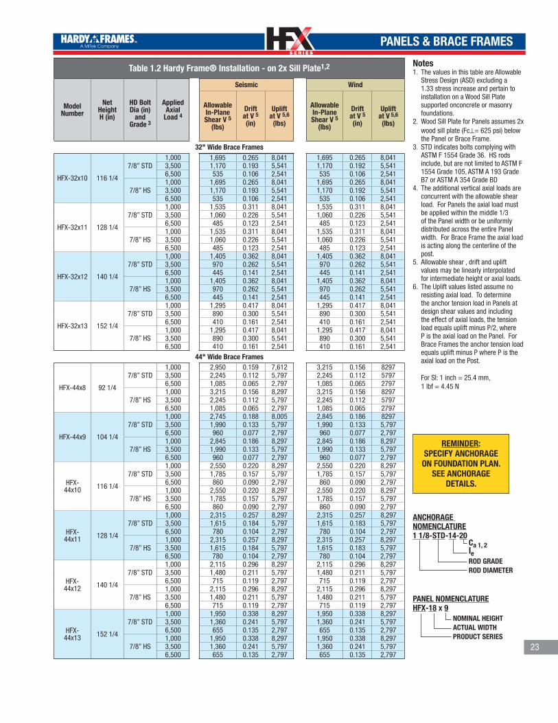
•Panels installed on wood sill plates have more ductility but, for some
sizes the allowable shear is less to account for crushing of wood below.
•Allowable values in Table 1.2 have been reduced when necessary to
maintain code drift limit.
•Because the Brace Frame base is wider, overturning forces cause less
compression on wood sill.
Installation: -Set bolts 4 1/4˝ inches above concrete
-Moisture barrier (15# felt, Moist Stop, Etc.) recommended when
installing on treated wood.
20

TM
TM
PANELS & BRACE FRAMES
21
Table 1.2 Hardy Frame® Installation - on 2x Sill Plate1,2
Model Number
NetHeightH (in)
HD BoltDia (in)
and Grade 3
AppliedAxial
Load 4
Seismic R=6.5 Wind
AllowableIn-PlaneShear V 5
(lbs)
Driftat V 5
(in)
Upliftat V 5,6
(lbs)
AllowableIn-PlaneShear V 5
(lbs)
Driftat V 5
(in)
Upliftat V 5,6
(lbs)
12" Wide Panels
HFX-12x78 78
1 1/8” STD1,000 1,067 0.341 11,499 1,132 0.373 12,2193,500 771 0.278 7,219 771 0.278 7,2196,500 339 0.167 1,219 339 0.167 1,219
1 1/8” HS1,000 1,067 0.341 11,492 1,132 0.373 12,2193,500 771 0.279 7,219 771 0.279 7,2196,500 339 0.167 1,219 339 0.167 1,219
HFX-12x8 92 1/4
1 1/8” STD1,000 907 0.404 11,565 957 0.438 12,2193,500 652 0.327 7,219 652 0.327 7,2196,500 286 0.196 1,219 286 0.196 1,219
1 1/8” HS1,000 906 0.404 11,549 957 0.439 12,2193,500 652 0.327 7,219 652 0.327 7,2196,500 286 0.197 1,219 286 0.197 1,219
HFX-12x9 104 1/4
1 1/8” STD1,000 806 0.456 11,608 847 0.492 12,2193,500 577 0.368 7,219 577 0.368 7,2196,500 253 0.221 1,219 253 0.221 1,219
1 1/8” HS1,000 805 0.456 11,590 847 0.493 12,2193,500 577 0.368 7,219 577 0.368 7,2196,500 253 0.221 1,219 253 0.221 1,219
HFX-12x10 116 1/4
1 1/8” STD1,000 725 0.508 11,641 759 0.546 12,2193,500 517 0.408 7,219 517 0.408 7,2196,500 227 0.246 1,219 227 0.246 1,219
1 1/8” HS1,000 724 0.508 11,628 759 0.547 12,2193,500 517 0.409 7,219 517 0.409 7,2196,500 227 0.246 1,219 227 0.246 1,219
18" Wide Panels
HFX-18x78 78
1 1/8” STD1,000 1,973 0.287 12,219 1,973 0.286 12,2193,500 1,380 0.219 7,219 1,380 0.219 7,2196,500 669 0.137 1,219 669 0.137 1,219
1 1/8” HS1,000 1,973 0.287 12,219 1,973 0.287 12,2193,500 1,380 0.219 7,219 1,380 0.219 7,2196,500 669 0.137 1,219 669 0.137 1,219
HFX-18x8 92 1/4
1 1/8” STD1,000 1,668 0.336 12,219 1,668 0.336 12,2193,500 1,167 0.257 7,219 1,167 0.257 7,2196,500 565 0.161 1,219 565 0.161 1,219
1 1/8” HS1,000 1,668 0.337 12,219 1,668 0.337 12,2193,500 1,167 0.257 7,219 1,167 0.257 7,2196,500 565 0.162 1,219 565 0.162 1,219
HFX-18x9 104 1/4
1 1/8” STD1,000 1,476 0.379 12,219 1,476 0.379 12,2193,500 1,033 0.289 7,219 1,033 0.289 7,2196,500 500 0.182 1,219 500 0.182 1,219
1 1/8” HS1,000 1,476 0.379 12,219 1,476 0.379 12,2193,500 1,033 0.290 7,219 1,033 0.290 7,2196,500 500 0.182 1,219 500 0.182 1,219
HFX-18x10 116 1/4
1 1/8” STD1,000 1,324 0.420 12,219 1,324 0.420 12,2193,500 926 0.321 7,219 926 0.321 7,2196,500 449 0.202 1,219 449 0.202 1,219
1 1/8” HS1,000 1,324 0.421 12,219 1,324 0.421 12,2193,500 926 0.322 7,219 926 0.322 7,2196,500 449 0.202 1,219 449 0.202 1,219
HFX-18x11 128 1/4
1 1/8” STD1,000 1,200 0.462 12,219 1,200 0.463 12,2193,500 839 0.353 7,219 839 0.354 7,2196,500 407 0.222 1,219 407 0.223 1,219
1 1/8” HS1,000 1,200 0.462 12,219 1,200 0.462 12,2193,500 839 0.353 7,219 839 0.353 7,2196,500 407 0.223 1,219 407 0.223 1,219
HFX-18x12 140 1/4
1 1/8” STD1,000 1,097 0.503 12,219 1,097 0.503 12,2193,500 768 0.385 7,219 768 0.385 7,2196,500 372 0.243 1,219 372 0.243 1,219
1 1/8” HS1,000 1,097 0.504 12,219 1,097 0.504 12,2193,500 768 0.385 7,219 768 0.385 7,2196,500 372 0.243 1,219 372 0.243 1,219

TM
TM
PANELS & BRACE FRAMES
22
Table 1.2 Hardy Frame® Installation - on 2x Sill Plate1,2
Model Number
NetHeightH (in)
HD BoltDia (in)
and Grade 3
AppliedAxial
Load 4
Seismic R=6.5 Wind
AllowableIn-PlaneShear V 5
(lbs)
Driftat V 5
(in)
Upliftat V 5,6
(lbs)
AllowableIn-PlaneShear V 5
(lbs)
Driftat V 5
(in)
Upliftat V 5,6
(lbs)
18" Wide Panels
HFX-18x13 152 1/4
1 1/8” STD1,000 1,011 0.543 12,219 1,011 0.544 12,2193,500 707 0.416 7,219 707 0.416 7,2196,500 343 0.262 1,219 343 0.263 1,219
1 1/8” HS1,000 1,011 0.545 12,219 1,011 0.545 12,2193,500 707 0.417 7,219 707 0.417 7,2196,500 343 0.263 1,219 343 0.263 1,219
24" Wide Panels
HFX-24x78 78
1 1/8” STD1,000 2,951 0.220 12,219 2,951 0.220 12,2193,500 2,070 0.168 7,219 2,070 0.168 7,2196,500 1,012 0.106 1,219 1,012 0.106 1,219
1 1/8” HS1,000 2,951 0.221 12,219 2,951 0.221 12,2193,500 2,070 0.169 7,219 2,070 0.169 7,2196,500 1,012 0.106 1,219 1,012 0.106 1,219
HFX-24x8 92 1/4
1 1/8” STD1,000 2,496 0.259 12,219 2,496 0.259 12,2193,500 1,750 0.198 7,219 1,750 0.198 7,2196,500 856 0.125 1,219 856 0.125 1,219
1 1/8” HS1,000 2,496 0.259 12,219 2,496 0.260 12,2193,500 1,750 0.198 7,219 1,750 0.199 7,2196,500 856 0.125 1,219 856 0.125 1,219
HFX-24x9 104 1/4
1 1/8” STD1,000 2,208 0.291 12,219 2,208 0.291 12,2193,500 1,549 0.222 7,219 1,549 0.223 7,2196,500 757 0.140 1,219 757 0.141 1,219
1 1/8” HS1,000 2,208 0.292 12,219 2,208 0.292 12,2193,500 1,549 0.223 7,219 1,549 0.223 7,2196,500 757 0.141 1,219 757 0.141 1,219
HFX-24x10 116 1/4
1 1/8” STD1,000 1,980 0.323 12,219 1,980 0.323 12,2193,500 1,389 0.247 7,219 1,389 0.247 7,2196,500 679 0.156 1,219 679 0.156 1,219
1 1/8” HS1,000 1,980 0.324 12,219 1,980 0.324 12,2193,500 1,389 0.248 7,219 1,389 0.248 7,2196,500 679 0.157 1,219 679 0.157 1,219
HFX-24x11 128 1/4
1 1/8” STD1,000 1,795 0.355 12,219 1,795 0.354 12,2193,500 1,259 0.272 7,219 1,259 0.271 7,2196,500 616 0.172 1,219 616 0.172 1,219
1 1/8” HS1,000 1,795 0.355 12,219 1,795 0.355 12,2193,500 1,259 0.271 7,219 1,259 0.272 7,2196,500 616 0.172 1,219 616 0.172 1,219
HFX-24x12 140 1/4
1 1/8” STD1,000 1,641 0.386 12,219 1,641 0.387 12,2193,500 1,151 0.296 7,219 1,151 0.296 7,2196,500 563 0.187 1,219 563 0.187 1,219
1 1/8” HS1,000 1,641 0.386 12,219 1,641 0.387 12,2193,500 1,151 0.296 7,219 1,151 0.296 7,2196,500 563 0.187 1,219 563 0.187 1,219
HFX-24x13 152 1/4
1 1/8” STD1,000 1,512 0.419 12,219 1,512 0.418 12,2193,500 1,061 0.321 7,219 1,061 0.320 7,2196,500 519 0.203 1,219 519 0.203 1,219
1 1/8” HS1,000 1,512 0.418 12,219 1,512 0.418 12,2193,500 1,061 0.320 7,219 1,061 0.320 7,2196,500 519 0.203 1,219 519 0.203 1,219
32" Wide Brace Frames
HFX-32x8 92 1/4
7/8” STD1,000 2,135 0.183 8,041 2,135 0.183 8,0413,500 1,470 0.134 5,541 1,470 0.134 5,5416,500 675 0.075 2,541 675 0.075 2,541
7/8” HS1,000 2,135 0.183 8,041 2,135 0.183 8,0413,500 1,470 0.134 5,541 1,470 0.134 5,5416,500 675 0.075 2,541 675 0.075 2,541
HFX-32x9 104 1/4
7/8” STD1,000 1,890 0.222 8,041 1,890 0.222 8,0413,500 1,300 0.162 5,541 1,300 0.162 5,5416,500 595 0.090 2,541 595 0.090 2,541
7/8” HS1,000 1,890 0.222 8,041 1,890 0.222 8,0413,500 1,300 0.162 5,541 1,300 0.162 5,5416,500 595 0.090 2,541 595 0.090 2,541
TM
TM
PANELS & BRACE FRAMES
23
Table 1.2 Hardy Frame® Installation - on 2x Sill Plate1,2
Model Number
NetHeightH (in)
HD BoltDia (in)
and Grade 3
AppliedAxial
Load 4
Seismic Wind
AllowableIn-PlaneShear V 5
(lbs)
Driftat V 5(in)
Upliftat V 5,6
(lbs)
AllowableIn-PlaneShear V 5
(lbs)
Driftat V 5(in)
Upliftat V 5,6
(lbs)
32" Wide Brace Frames
HFX-32x10 116 1/4
7/8” STD1,000 1,695 0.265 8,041 1,695 0.265 8,0413,500 1,170 0.193 5,541 1,170 0.192 5,5416,500 535 0.106 2,541 535 0.106 2,541
7/8” HS1,000 1,695 0.265 8,041 1,695 0.265 8,0413,500 1,170 0.193 5,541 1,170 0.192 5,5416,500 535 0.106 2,541 535 0.106 2,541
HFX-32x11 128 1/4
7/8” STD1,000 1,535 0.311 8,041 1,535 0.311 8,0413,500 1,060 0.226 5,541 1,060 0.226 5,5416,500 485 0.123 2,541 485 0.123 2,541
7/8” HS1,000 1,535 0.311 8,041 1,535 0.311 8,0413,500 1,060 0.226 5,541 1,060 0.226 5,5416,500 485 0.123 2,541 485 0.123 2,541
HFX-32x12 140 1/4
7/8” STD1,000 1,405 0.362 8,041 1,405 0.362 8,0413,500 970 0.262 5,541 970 0.262 5,5416,500 445 0.141 2,541 445 0.141 2,541
7/8” HS1,000 1,405 0.362 8,041 1,405 0.362 8,0413,500 970 0.262 5,541 970 0.262 5,5416,500 445 0.141 2,541 445 0.141 2,541
HFX-32x13 152 1/4
7/8” STD1,000 1,295 0.417 8,041 1,295 0.417 8,0413,500 890 0.300 5,541 890 0.300 5,5416,500 410 0.161 2,541 410 0.161 2,541
7/8” HS1,000 1,295 0.417 8,041 1,295 0.417 8,0413,500 890 0.300 5,541 890 0.300 5,5416,500 410 0.161 2,541 410 0.161 2,541
44" Wide Brace Frames
HFX-44x8 92 1/4
7/8” STD1,000 2,950 0.159 7,612 3,215 0.156 82973,500 2,245 0.112 5,797 2,245 0.112 57976,500 1,085 0.065 2,797 1,085 0.065 2797
7/8” HS1,000 3,215 0.156 8,297 3,215 0.156 82973,500 2,245 0.112 5,797 2,245 0.112 57976,500 1,085 0.065 2,797 1,085 0.065 2797
HFX-44x9 104 1/4
7/8” STD1,000 2,745 0.188 8,005 2,845 0.186 82973,500 1,990 0.133 5,797 1,990 0.133 5,7976,500 960 0.077 2,797 960 0.077 2,797
7/8” HS1,000 2,845 0.186 8,297 2,845 0.186 8,2973,500 1,990 0.133 5,797 1,990 0.133 5,7976,500 960 0.077 2,797 960 0.077 2,797
HFX-44x10 116 1/4
7/8” STD1,000 2,550 0.220 8,297 2,550 0.220 8,2973,500 1,785 0.157 5,797 1,785 0.157 5,7976,500 860 0.090 2,797 860 0.090 2,797
7/8” HS1,000 2,550 0.220 8,297 2,550 0.220 8,2973,500 1,785 0.157 5,797 1,785 0.157 5,7976,500 860 0.090 2,797 860 0.090 2,797
HFX-44x11 128 1/4
7/8” STD1,000 2,315 0.257 8,297 2,315 0.257 8,2973,500 1,615 0.184 5,797 1,615 0.183 5,7976,500 780 0.104 2,797 780 0.104 2,797
7/8” HS1,000 2,315 0.257 8,297 2,315 0.257 8,2973,500 1,615 0.184 5,797 1,615 0.183 5,7976,500 780 0.104 2,797 780 0.104 2,797
HFX-44x12 140 1/4
7/8” STD1,000 2,115 0.296 8,297 2,115 0.296 8,2973,500 1,480 0.211 5,797 1,480 0.211 5,7976,500 715 0.119 2,797 715 0.119 2,797
7/8” HS1,000 2,115 0.296 8,297 2,115 0.296 8,2973,500 1,480 0.211 5,797 1,480 0.211 5,7976,500 715 0.119 2,797 715 0.119 2,797
HFX-44x13 152 1/4
7/8” STD1,000 1,950 0.338 8,297 1,950 0.338 8,2973,500 1,360 0.241 5,797 1,360 0.241 5,7976,500 655 0.135 2,797 655 0.135 2,797
7/8” HS1,000 1,950 0.338 8,297 1,950 0.338 8,2973,500 1,360 0.241 5,797 1,360 0.241 5,7976,500 655 0.135 2,797 655 0.135 2,797
Notes1. The values in this table are Allowable
Stress Design (ASD) excluding a 1.33 stress increase and pertain to installation on a Wood Sill Plate supported onconcrete or masonry foundations.
2. Wood Sill Plate for Panels assumes 2x wood sill plate (Fc⊥= 625 psi) below the Panel or Brace Frame.
3. STD indicates bolts complying with ASTM F 1554 Grade 36. HS rods include, but are not limited to ASTM F 1554 Grade 105, ASTM A 193 Grade B7 or ASTM A 354 Grade BD
4. The additional vertical axial loads are concurrent with the allowable shear load. For Panels the axial load must be applied within the middle 1/3 of the Panel width or be uniformly distributed across the entire Panel width. For Brace Frame the axial load is acting along the centerline of the post.
5. Allowable shear , drift and uplift values may be linearly interpolated for intermediate height or axial loads.
6. The Uplift values listed assume no resisting axial load. To determine the anchor tension load in Panels at design shear values and including the effect of axial loads, the tension load equals uplift minus P/2, where P is the axial load on the Panel. For Brace Frames the anchor tension load equals uplift minus P where P is the axial load on the Post. For SI: 1 inch = 25.4 mm, 1 lbf = 4.45 N
NOMINAL HEIGHTACTUAL WIDTHPRODUCT SERIES
PANEL NOMENCLATUREHFX-18 x 9
Ca 1, 2leROD GRADEROD DIAMETER
ANCHORAGE NOMENCLATURE1 1/8-STD-14-20
REMINDER:SPECIFY ANCHORAGE
ON FOUNDATION PLAN.SEE ANCHORAGE
DETAILS.
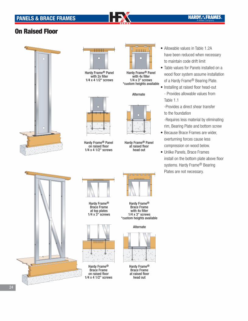
TM
TM
PANELS & BRACE FRAMES
On Raised Floor
HARDY FRAME PANEL WITH 2X FILLER®
Hardy Frame® Panel with 2x filler
1/4 x 4 1/2" screws
HARDY FRAME PANEL WITH 4X FILLER
®
Hardy Frame® Panel with 4x filler
1/4 x 3" screws*custom heights available
HARDY FRAME PANEL BOTTOMON RAISED FLOOR ON CONCRETE
®
Hardy Frame® Panel at raised floor
head outHARDY FRAME PANEL BOTTOMON RAISED FLOOR
®
HARDY FRAME BRACE FRAMETOP WITH TOP PLATE
®
HARDY FRAME BRACE FRAME4X FILLER
®
Hardy Frame® Brace Frameat top plates
1/4 x 3" screws
Hardy Frame® Brace Framewith 4x filler
1/4 x 3" screws*custom heights available
HARDY FRAME BRACE FRAMEBOTTOM ON RAISED FLOOR
®HARDY FRAME BRACE FRAMEBOTTOM ON RAISED FLOOR HEAD OUT
®
Hardy Frame® Panel on raised floor
1/4 x 4 1/2" screws
Hardy Frame® Brace Frame
on raised floor1/4 x 4 1/2" screws
Hardy Frame® Brace Frameat raised floor
head out
Alternate
Alternate
•Allowable values in Table 1.2A
have been reduced when necessary
to maintain code drift limit
•Table values for Panels installed on a
wood floor system assume installation
of a Hardy Frame® Bearing Plate.
• Installing at raised floor head-out
- Provides allowable values from
Table 1.1
-Provides a direct shear transfer
to the foundation
-Requires less material by eliminating
rim, Bearing Plate and bottom screw
•Because Brace Frames are wider,
overturning forces cause less
compression on wood below.
•Unlike Panels, Brace Frames
install on the bottom plate above floor
systems. Hardy Frame® Bearing
Plates are not necessary.
24

TM
TM
PANELS & BRACE FRAMES
25
Table 1.2A Hardy Frame® Installation - on Raised Floors1,2
Model Number
NetHeightH (in)
HD RodDia (in)
and Grade 3
AllowableAxial
Load 4
Seismic R=6.5 Wind AllowableIn-PlaneShear V 5
(lbs)
Driftat V 5
(in)
Upliftat V 5,6
(lbs)
AllowableIn-PlaneShear V 5
(lbs)
Driftat V 5
(in)
Upliftat V 5,6
(lbs)
12" Wide Panels
HFX-12x78 78
1 1/8" STD1,000 1,380 0.341 12,165 1,755 0.433 15,5853,500 1,350 0.341 10,625 1,685 0.433 13,7206,500 1,310 0.341 8,775 1,400 0.363 9,610
1 1/8" HS1,000 1,380 0.341 12,150 1,750 0.433 15,5653,500 1,345 0.341 10,610 1,685 0.433 13,7056,500 1,310 0.341 8,760 1,400 0.364 9,610
HFX-12x8 92 1/4
1 1/8" STD1,000 1,180 0.404 12,305 1,490 0.512 15,6903,500 1,155 0.404 10,760 1,435 0.512 13,8206,500 1,120 0.404 8,910 1,185 0.426 9,610
1 1/8" HS1,000 1,175 0.404 12,270 1,490 0.512 15,6703,500 1,150 0.404 10,725 1,435 0.512 13,8056,500 1,115 0.404 8,875 1,185 0.426 9,610
HFX-12x9 104 1/4
1 1/8" STD1,000 1,050 0.456 12,395 1,325 0.579 15,7703,500 1,030 0.456 10,850 1,275 0.579 13,9006,500 1,000 0.456 8,995 1,050 0.478 9,610
1 1/8" HS1,000 1,050 0.456 12,360 1,325 0.579 15,7453,500 1,025 0.456 10,815 1,275 0.579 13,8756,500 995 0.456 8,960 1,050 0.479 9,610
HFX-12x10 116 1/4
1 1/8" STD1,000 950 0.509 12,475 1,195 0.646 15,8353,500 925 0.509 10,925 1,150 0.646 13,9656,500 900 0.509 9,070 940 0.530 9,610
1 1/8" HS1,000 945 0.509 12,445 1,195 0.646 15,8103,500 925 0.509 10,900 1,145 0.646 13,9406,500 900 0.509 9,040 940 0.531 9,610
18" Wide Panels
HFX-18x78 78
1 1/8" STD1,000 2,875 0.341 15,935 3,430 0.433 19,1003,500 2,780 0.341 14,055 3,050 0.386 15,6106,500 2,285 0.279 9,610 2,285 0.278 9,610
1 1/8" HS1,000 2,875 0.341 15,925 3,425 0.433 19,0703,500 2,780 0.341 14,045 3,050 0.387 15,6106,500 2,285 0.279 9,610 2,285 0.279 9,610
HFX-18x8 92 1/4
1 1/8"STD1,000 2,450 0.404 16,055 2,920 0.512 192303,500 2,370 0.404 14,170 2,580 0.453 15,6106,500 1,930 0.326 9,610 1,930 0.326 9,610
1 1/8" HS1,000 2,445 0.404 16,025 2,910 0.512 19,1703,500 2,365 0.404 14,140 2,580 0.455 15,6106,500 1,930 0.327 9,610 1,930 0.328 9,610
HFX-18x9 104 1/4
1 1/8" STD1,000 2,175 0.456 16,100 2,590 0.579 19,2853,500 2,100 0.456 14,215 2,285 0.510 15,6106,500 1,710 0.367 9,610 1,710 0.367 9,610
1 1/8" HS1,000 2,170 0.456 16,090 2,585 0.579 19,2503,500 2,100 0.456 14,200 2,285 0.511 15,6106,500 1,710 0.368 9,610 1,710 0.368 9,610
HFX-18x10 116 1/4
1 1/8" STD1,000 1,960 0.509 16,190 2,335 0.646 19,3803,500 1,895 0.509 14,300 2,050 0.565 15,6106,500 1,530 0.407 9,610 1,530 0.407 9,610
1 1/8" HS1,000 1,955 0.509 16,145 2,330 0.646 19,3303,500 1,890 0.509 14,260 2,050 0.567 15,6106,500 1,530 0.408 9,610 1,530 0.408 9,610
HFX-18x11 128 1/4
1 1/8" STD1,000 1,780 0.561 16,240 2,115 0.712 19,3753,500 1,720 0.561 14,345 1,855 0.623 15,6106,500 1,390 0.447 9,610 1,390 0.449 9,610
1 1/8" HS1,000 1,780 0.561 16,225 2,120 0.712 19,4203,500 1,720 0.561 14,330 1,855 0.622 15,6106,500 1,390 0.448 9,610 1,390 0.448 9,610
HFX-18x12 140 1/4
1 1/8" STD1,000 1,635 0.614 16,295 1,945 0.779 19,5053,500 1,580 0.614 14,400 1,695 0.676 15,6106,500 1,270 0.487 9,610 1,270 0.487 9,610
1 1/8" HS1,000 1,630 0.614 16,270 1,945 0.779 19,4753,500 1,580 0.614 14,375 1,695 0.677 15,6106,500 1,270 0.488 9,610 1,270 0.488 9,610
HFX-18x13 152 1/4
1 1/8" STD1,000 1,510 0.666 16,360 1,800 0.846 19,5803,500 1,460 0.666 14,465 1,565 0.730 15,6106,500 1,170 0.525 9,610 1,170 0.525 9,610
1 1/8" HS1,000 1,510 0.666 16,320 1,795 0.846 19,5403,500 1,460 0.666 14,425 1,565 0.732 15,6106,500 1,170 0.527 9,610 1,170 0.527 9,610

TM
TM
PANELS & BRACE FRAMES
26
Table 1.2A Hardy Frame® Installation - on Raised Floors1,2
Model Number
NetHeightH (in)
HD RodDia (in)
and Grade 3
AllowableAxial
Load 4
Seismic R=6.5 Wind
AllowableIn-PlaneShear V 5
(lbs)
Driftat V 5
(in)
Upliftat V 5,6
(lbs)
AllowableIn-PlaneShear V 5
(lbs)
Driftat V 5
(in)
Upliftat V 5,6
(lbs)
24" Wide Panels
HFX-24x78 78
1 1/8" STD
1,0003,830
0.236 14,700 5,105 0.343 19,770
3,500 0.243 13,395 4,385 0.292 15,610
6,500 3,270 0.210 9,610 3,270 0.210 9,610
1 1/8" HS
1,000 5,070 0.341 19,620 5,315 0.363 20,610
3,500 4,385 0.293 15,610 4,385 0.293 15,610
6,500 3,270 0.211 9,610 3,270 0.211 9,610
HFX-24x8 92 1/4
1 1/8" STD
1,0003,420
0.292 15,555 4,495 0.425 20,610
3,500 0.307 14,250 3,710 0.343 15,610
6,500 2,765 0.246 9,610 2,765 0.247 9,610
1 1/8" HS
1,000 4,315 0.404 19,770 4,495 0.426 20,610
3,500 3,710 0.344 15,610 3,710 0.344 15,610
6,500 2,765 0.247 9,610 2,765 0.248 9,610
HFX-24x9 104 1/4
1 1/8" STD
1,0003,140
0.346 16,160 3,980 0.477 20,610
3,500 0.362 14,850 3,285 0.385 15,610
6,500 2,450 0.277 9,610 2,450 0.277 9,610
1 1/8" HS
1,000 3,835 0.456 19,855 3,980 0.478 20,610
3,500 3,285 0.386 15,610 3,285 0.386 15,610
6,500 2,450 0.278 9,610 2,450 0.278 9,610
HFX-24x10 116 1/4
1 1/8" STD
1,0002,900
0.400 16,655 3,565 0.529 20,610
3,500 0.418 15,350 2,945 0.427 15,610
6,500 2,195 0.307 9,610 2,195 0.307 9,610
1 1/8" HS
1,000 3,450 0.509 19,910 3,565 0.531 20,610
3,500 2,945 0.429 15,610 2,945 0.429 15,610
6,500 2,195 0.309 9,610 2,195 0.308 9,610
HFX-24x11 128 1/4
1 1/8" STD
1,000 2,695 0.455 17,090 3,235 0.580 20,610
3,500 2,670 0.469 15,610 2,670 0.468 15,610
6,500 1,990 0.337 9,610 1,990 0.337 9,610
1 1/8"HS
1,000 3,150 0.561 20,070 3,235 0.581 20,610
3,500 2,670 0.468 15,610 2,670 0.469 15,610
6,500 1,990 0.337 9,610 1,990 0.337 9,610
HFX-24x12 140 1/4
1 1/8" STD
1,000 2,515 0.509 17,450 2,955 0.633 20,610
3,500 2,440 0.510 15,610 2,440 0.511 15,610
6,500 1,820 0.367 9,610 1,820 0.367 9,610
1 1/8" HS
1,000 2,890 0.614 20,130 2,955 0.633 20,610
3,500 2,440 0.510 15,610 2,440 0.511 15,610
6,500 1,820 0.367 9,610 1,820 0.367 9,610
HFX-24x13 152 1/4
1 1/8" STD
1,000 2,360 0.566 17,785 2,725 0.684 20,610
3,500 2,250 0.553 15,610 2,250 0.552 15,610
6,500 1,675 0.397 9,610 1,675 0.397 9,610
1 1/8" HS
1,000 2,670 0.666 20,180 2,725 0.684 20,610
3,500 2,250 0.552 15,610 2,250 0.552 15,610
6,500 1,675 0.397 9,610 1,675 0.397 9,610
32" Wide Brace Frames
HFX-32x8 92 1/4
7/8" STD1,000 2,135 0.310 8,040 2,135 0.310 8,0403,500 1,470 0.229 5,540 1,470 0.229 5,5406,500 675 0.139 2,540 675 0.139 2,540
7/8" HS1,000 2,135 0.310 8,040 2,135 0.310 8,0403,500 1,470 0.229 5,540 1,470 0.229 5,5406,500 675 0.139 2,540 675 0.139 2,540

TM
TM
PANELS & BRACE FRAMES
27
Notes 1. The values in this table are Allowable
Stress Design (ASD) excluding a 1.33 stress increase and pertain to installation on Raised Floor Systems supported on concrete or masonry foundations.
2. Raised Floor System for Panels assume a 2x wood sill plate, EWP rim board (Fc⊥ = 680 psi, 12 inch depth) with a Hardy Frame® Bearing Plate installed below. For EWP rim boards up to 18 inches deep the allowable shear value must be multiplied by 0.96 for 12 inch Panel widths and by 0.98 for 18 and 24 inchPanel widths. For all Panel widths the corre-sponding drift does not change. Raised Floor System for Brace Frames assume a 2x wood sill plate, EWP rim board (Fc⊥= 680 psi,12 inch deep), floor sheathing and a 2x wood bottom plate (Fc⊥=625 psi) below. For EWP rim boards up to 18 inches deep the allowable shear value does not change and the corresponding drift must be multiplied by 1.03.
3. STD indicates Rods complying with ASTM F 1554 Grade 36. HS rods include, but are not limited to ASTM F 1554 Grade 105, ASTM A 193 Grade B7 or ASTM A 354 Grade BD
4. The additional vertical axial loads are concurrent with the allowable shear load. For Panels the axial load must be applied within the middle 1/3 of the Panel width or be uniformly distributed across the entire Panel width. For Brace Frame the axial load is acting along the centerline of the post.
5. Allowable shear, drift and uplift values may be linearly interpolated for intermedi-ate height or axial loads.
6. The Uplift values listed assume no resisting axial load. To determine the anchor tension load in Panels at design shear values and including the effect of axial loads, the tension load equals uplift minus P/2, where P is the axial load on the Panel. For Brace Frames the anchor tension load equals uplift minus P where P is the axial load on the Post. REMINDER: SPECIFY ANCHOR-
AGE ON FOUNDATION PLAN. SEE ANCHORAGE DETAILS.
Table 1.2A Hardy Frame® Installation - on Raised Floors1,2
Model Number
NetHeightH (in)
HD RodDia (in)
and Grade 3
AllowableAxial
Load 4
Seismic R=6.5 Wind AllowableIn-PlaneShear V 5
(lbs)
Driftat V 5
(in)
Upliftat V 5,6
(lbs)
AllowableIn-PlaneShear V 5
(lbs)
Driftat V 5
(in)
Upliftat V 5,6
(lbs)
32" Wide Brace Frames
HFX-32x9 104 1/4
7/8" STD1,000 1,890 0.365 8,040 1,890 0.365 8,0403,500 1,300 0.269 5,540 1,300 0.269 5,5406,500 595 0.162 2,540 595 0.162 2,540
7/8" HS1,000 1,890 0.365 8,040 1,890 0.365 8,0403,500 1,300 0.269 5,540 1,300 0.269 5,5406,500 595 0.162 2,540 595 0.162 2,540
HFX-32x10 116 1/4
7/8" STD1,000 1,695 0.425 8,040 1,695 0.425 8,0403,500 1,170 0.312 5,540 1,170 0.312 5,5406,500 535 0.186 2,540 535 0.186 2,540
7/8" HS1,000 1,695 0.425 8,040 1,695 0.425 8,0403,500 1,170 0.312 5,540 1,170 0.312 5,5406,500 535 0.186 2,540 535 0.186 2,540
HFX-32x11 128 1/4
7/8" STD1,000 1,535 0.488 8,040 1,535 0.488 8,0403,500 1,060 0.358 5,540 1,060 0.358 5,5406,500 485 0.211 2,540 485 0.212 2,540
7/8" HS1,000 1,535 0.488 8,040 1,535 0.488 8,0403,500 1,060 0.358 5,540 1,060 0.358 5,5406,500 485 0.212 2,540 485 0.212 2,540
HFX-32x12 140 1/4
7/8" STD1,000 1,405 0.556 8,040 1,405 0.556 8,0403,500 970 0.406 5,540 970 0.407 5,5406,500 445 0.238 2,540 445 0.238 2,540
7/8" HS1,000 1,405 0.556 8,040 1,405 0.556 8,0403,500 970 0.406 5,540 970 0.406 5,5406,500 445 0.238 2,540 445 0.238 2,540
HFX-32x13 152 1/4
7/8" STD1,000 1,295 0.626 8,040 1,295 0.626 8,0403,500 890 0.457 5,540 890 0.457 5,5406,500 410 0.266 2,540 410 0.266 2,540
7/8" HS1,000 1,295 0.627 8,040 1,295 0.627 8,0403,500 890 0.457 5,540 890 0.457 5,5406,500 410 0.266 2,540 410 0.266 2,540
44" Wide Brace Frames
HFX-44x8 92 1/4
7/8" STD1,000 2,950 0.269 7,610 3,215 0.264 8,2953,500 2,245 0.188 5,795 2,245 0.188 5,7956,500 1,085 0.118 2,795 1,085 0.118 2,795
7/8" HS1,000 3,215 0.263 8,295 3,215 0.263 8,2953,500 2,245 0.188 5,795 2,245 0.188 5,7956,500 1,085 0.118 2795 1,085 0.118 2,795
HFX-44x9 104 1/4
7/8" STD1,000 2,745 0.312 8,005 2,845 0.308 8,2953,500 1,990 0.219 5,795 1,990 0.220 5,7956,500 960 0.136 2,795 960 0.136 2,795
7/8" HS1,000 2,845 0.308 8,295 2,845 0.308 8,2953,500 1,990 0.220 5,795 1,990 0.220 5,7956,500 960 0.136 2,795 960 0.136 2,795
HFX-44x10 116 1/4
7/8" STD1,000 2,550 0.356 8,295 2,550 0.356 8,2953,500 1,785 0.254 5,795 1,785 0.254 5,7956,500 860 0.156 2,795 860 0.156 2,795
7/8" HS1,000 2,550 0.356 8,295 2,550 0.356 8,2953,500 1,785 0.254 5,795 1,785 0.254 5,7956,500 860 0.156 2,795 860 0.156 2,795
HFX-44x11 128 1/4
7/8" STD1,000 2,315 0.407 8,295 2,315 0.406 8,2953,500 1,615 0.290 5,795 1,615 0.289 5,7956,500 780 0.177 2,795 780 0.177 2,795
7/8" HS1,000 2,315 0.406 8,295 2315 0.406 8,2953,500 1,615 0.289 5,795 1,615 0.289 5,7956,500 780 0.177 2,795 780 0.177 2,795
HFX-44x12 140 1/4
7/8" STD1,000 2,115 0.459 8,295 2,115 0.459 8,2953,500 1,480 0.327 5,795 1,480 0.327 5,7956,500 715 0.199 2,795 715 0.199 2,795
7/8" HS1,000 2,115 0.460 8,295 2,115 0.460 8,2953,500 1,480 0.327 5,795 1,480 0.327 5,7956,500 715 0.199 2,795 715 0.199 2,795
HFX-44x13 152 1/4
7/8" STD1,000 1,950 0.516 8,295 1,950 0.516 8,2953,500 1,360 0.367 5,795 1,360 0.367 5,7956,500 655 0.221 2,795 655 0.221 2,795
7/8" HS1,000 1,950 0.516 8,295 1,950 0.516 8,2953,500 1,360 0.367 5,795 1,360 0.367 5,7956,500 655 0.221 2,795 655 0.221 2,795
For SI: 1 inch = 25.4 mm, 1 lbf = 4.45 N
NOMINAL HEIGHTACTUAL WIDTHPRODUCT SERIES
PANEL NOMENCLATUREHFX-18 x 9
Ca 1, 2leROD GRADEROD DIAMETER
ANCHORAGE NOMENCLATURE1 1/8-STD-14-20
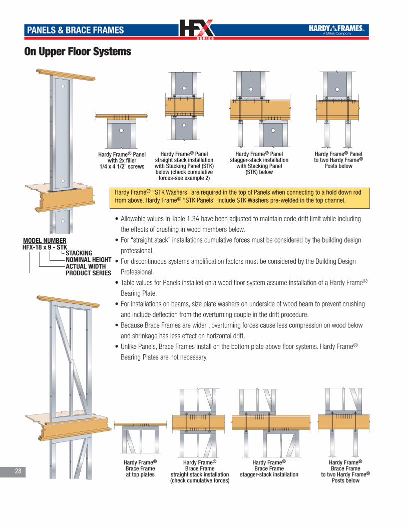
TM
TM
PANELS & BRACE FRAMES
On Upper Floor Systems
HARDY FRAME PANEL WITH 2X FILLER®
Hardy Frame® Panel with 2x filler
1/4 x 4 1/2" screwsHARDY FRAME PANEL BOTTOMON MULTI STORY
®
HARDY FRAME BRACE FRAMETOP WITH TOP PLATE
®
Hardy Frame® Brace Frameat top plates HARDY FRAME BRACE FRAME
BOTTOM ON MULTI STORY
®
Hardy Frame® Panel straight stack installationwith Stacking Panel (STK) below (check cumulative
forces-see example 2)
Hardy Frame® Brace Frame
straight stack installation(check cumulative forces)
Hardy Frame® Panel stagger-stack installation
with Stacking Panel (STK) below
Hardy Frame® Brace Frame
stagger-stack installation
Hardy Frame® Panel to two Hardy Frame®
Posts below
Hardy Frame® Brace Frame
to two Hardy Frame® Posts below
HARDY FRAME PANEL BOTTOMSTAGGER STACK
®HARDY FRAME PANEL BOTTOM2 POSTS
®
HARDY FRAME BRACE FRAMEBOTTOM STAGGER
®HARDY FRAME BRACE FRAMEBOTTOM 2 POSTS
®
Hardy Frame® "STK Washers" are required in the top of Panels when connecting to a hold down rod from above. Hardy Frame® "STK Panels" include STK Washers pre-welded in the top channel.
•Allowable values in Table 1.3A have been adjusted to maintain code drift limit while including
the effects of crushing in wood members below.
•For “straight stack” installations cumulative forces must be considered by the building design
professional.
•For discontinuous systems amplification factors must be considered by the Building Design
Professional.
•Table values for Panels installed on a wood floor system assume installation of a Hardy Frame®
Bearing Plate.
•For installations on beams, size plate washers on underside of wood beam to prevent crushing
and include deflection from the overturning couple in the drift procedure.
•Because Brace Frames are wider , overturning forces cause less compression on wood below
and shrinkage has less effect on horizontal drift.
•Unlike Panels, Brace Frames install on the bottom plate above floor systems. Hardy Frame®
Bearing Plates are not necessary.
STACKING NOMINAL HEIGHTACTUAL WIDTHPRODUCT SERIES
MODEL NUMBERHFX-18 x 9 - STK
28

TM
TM
PANELS & BRACE FRAMES
29
Table 1.3A Hardy Frame® Installation - on Upper Floors1,2
Model Number
NetHeightH (in)
HD RodDia (in)
and Grade 3
AllowableAxial
Load 4
Seismic R=6.5 Wind
AllowableIn-PlaneShear V5
(lbs)
Driftat V 5(in)
Upliftat V 5,6
(lbs)
AllowableIn-PlaneShear V5
(lbs)
Driftat V 5(in)
Upliftat V 5,6
(lbs)
12" Wide Panels
HFX-12x78 78
1 1/8" STD1,000 1,245 0.341 10,940 1,590 0.433 14,0753,500 1,210 0.341 9,350 1,550 0.433 12,4856,500 1,165 0.341 7,440 1,400 0.405 9,610
1 1/8" HS1,000 1,245 0.341 10,930 1,585 0.433 14,0553,500 1,210 0.341 9,340 1,550 0.433 12,4606,500 1,165 0.341 7,425 1,400 0.406 9,610
HFX-12x8 92 1/4
1 1/8" STD1,000 1,065 0.404 11,060 1,355 0.512 14,2053,500 1,035 0.404 9,460 1,325 0.512 12,6106,500 995 0.404 7,545 1,185 0.475 9,610
1 1/8" HS1,000 1,060 0.404 11,030 1,355 0.512 14,1803,500 1,030 0.404 9,435 1,320 0.512 12,5856,500 990 0.404 7,520 1,185 0.476 9,610
HFX-12x9 104 1/4
1 1/8" STD1,000 950 0.456 11,135 1,205 0.579 14,3053,500 920 0.456 9,535 1,180 0.579 12,7056,500 885 0.456 7,615 1,050 0.533 9,610
1 1/8" HS1,000 945 0.456 11,105 1,205 0.579 14,2753,500 920 0.456 9,505 1,175 0.579 12,6756,500 885 0.456 7,590 1,050 0.534 9,610
HFX-12x10 116 1/4
1 1/8" STD1,000 855 0.509 11,195 1,090 0.646 14,3903,500 830 0.508 9,595 1,065 0.646 12,7906,500 800 0.509 7,675 940 0.592 9,610
1 1/8" HS1,000 855 0.509 11,170 1,085 0.646 14,3603,500 830 0.508 9,570 1,060 0.646 12,7606,500 795 0.509 7,650 940 0.593 9,610
18" Wide Panels
HFX-18x78 78
1 1/8" STD1,000 2,665 0.341 14,725 3,225 0.433 17,9203,500 2,605 0.341 13,040 3,050 0.421 15,6106,500 2,285 0.307 9,610 2,285 0.306 9,610
1 1/8" HS1,000 2,665 0.341 14,715 3,220 0.433 17,8903,500 2,600 0.341 13,035 3,050 0.421 15,6106,500 2,285 0.307 9,610 2,285 0.307 9,610
HFX-18x8 92 1/4
1 1/8" STD1,000 2,275 0.404 14,875 2,740 0.512 18,0303,500 2,215 0.404 13,145 2,580 0.493 15,6106,500 1,930 0.360 9610 1,930 0.360 9,610
1 1/8" HS1,000 2,270 0.404 14,835 2,735 0.512 17,9803,500 2,215 0.404 13,120 2,580 0.495 15,6106,500 1,930 0.361 9,610 1,930 0.361 9,610
HFX-18x9 104 1/4
1 1/8" STD1,000 2,020 0.456 14,930 2,430 0.579 18,0803,500 1,965 0.456 13,185 2,285 0.556 15,6106,500 1,710 0.405 9,610 1,710 0.405 9,610
1 1/8" HS1,000 2,020 0.456 14,915 2,430 0.579 18,0503,500 1,965 0.456 13,170 2,285 0.557 15,6106,500 1,710 0.406 9,610 1,710 0.406 9,610
HFX-18x10 116 1/4
1 1/8" STD1,000 1,825 0.509 15,040 2,190 0.646 18,1653,500 1,770 0.509 13,255 2,050 0.616 15,6106,500 1,530 0.449 9,610 1,530 0.449 9,610
1 1/8" HS1,000 1,820 0.509 14985 2,185 0.646 18,1203,500 1,770 0.509 13,220 2,050 0.618 15,6106,500 1,530 0.450 9,610 1,530 0.450 9,610
HFX-18x11 128 1/4
1 1/8" STD1,000 1,660 0.561 15,100 1,985 0.712 18,1603,500 1,610 0.561 13,300 1,855 0.680 15,6106,500 1,390 0.493 9,610 1,390 0.495 9,610
1 1/8" HS1,000 1,660 0.561 15,080 1,990 0.712 18,2003,500 1,610 0.561 13,285 1,855 0.678 15,6106,500 1,390 0.494 9,610 1,390 0.494 9,610
HFX-18x12 140 1/4
1 1/8" STD1,000 1,525 0.614 15,165 1,825 0.779 18,2753,500 1,480 0.614 13,350 1,695 0.738 15,6106,500 1,270 0.537 9,610 1,270 0.537 9,610
1 1/8" HS1,000 1,520 0.614 15,135 1,825 0.779 18,2453,500 1,475 0.614 13,325 1,695 0.739 15,6106,500 1,270 0.538 9,610 1,270 0.538 9,610
HFX-18x13 152 1/4
1 1/8" STD1,000 1,410 0.666 15,250 1,690 0.846 18,3403,500 1,365 0.666 13,400 1,565 0.797 15,6106,500 1,170 0.580 9,610 1,170 0.580 9,610
1 1/8" HS1,000 1,410 0.666 15,200 1,685 0.846 18,3053,500 1,365 0.666 13,370 1,565 0.799 15,6106,500 1170 0.582 9,610 1,170 0.582 9,610
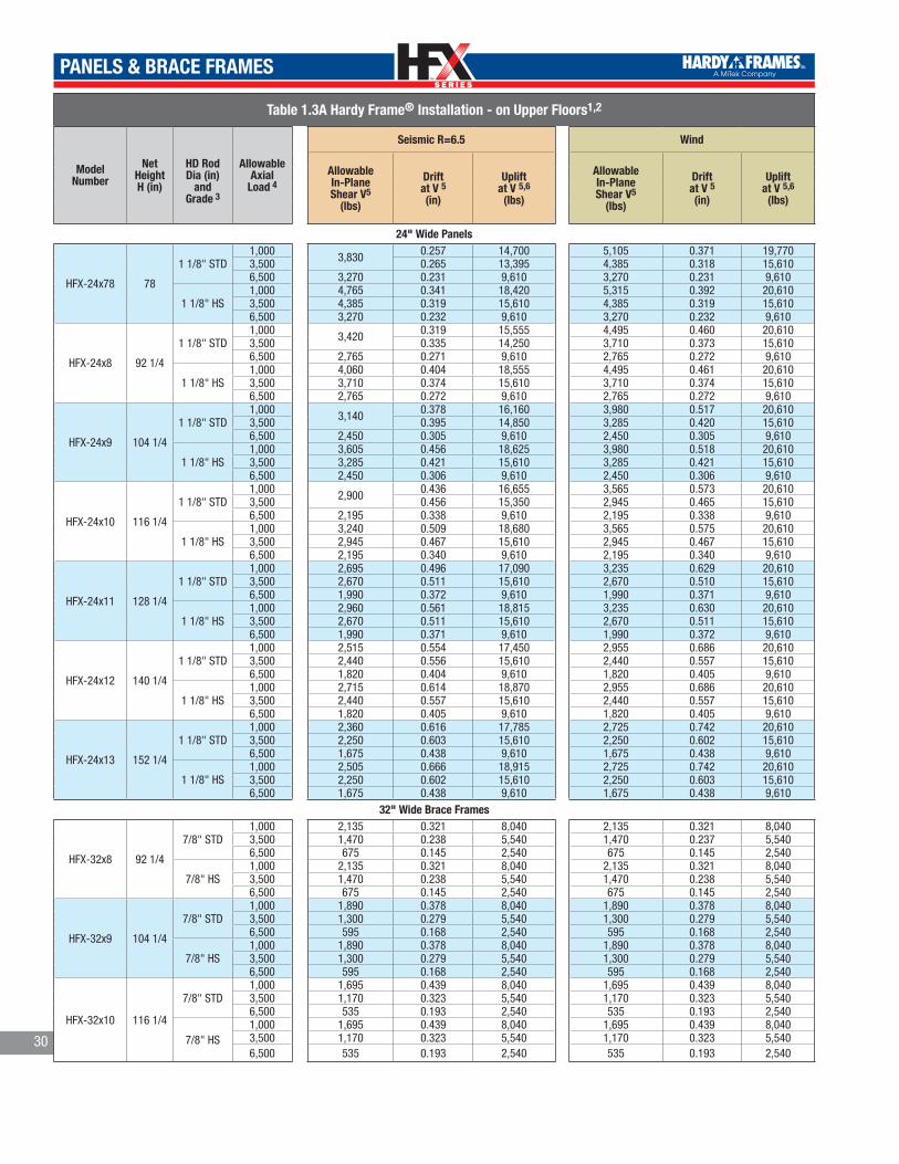
TM
TM
PANELS & BRACE FRAMES
30
Table 1.3A Hardy Frame® Installation - on Upper Floors1,2
Model Number
NetHeightH (in)
HD RodDia (in)
and Grade 3
AllowableAxial
Load 4
Seismic R=6.5 Wind
AllowableIn-PlaneShear V5
(lbs)
Driftat V 5(in)
Upliftat V 5,6
(lbs)
AllowableIn-PlaneShear V5
(lbs)
Driftat V 5(in)
Upliftat V 5,6
(lbs)
24" Wide Panels
HFX-24x78 78
1 1/8" STD1,000 3,830 0.257 14,700 5,105 0.371 19,7703,500 0.265 13,395 4,385 0.318 15,6106,500 3,270 0.231 9,610 3,270 0.231 9,610
1 1/8" HS1,000 4,765 0.341 18,420 5,315 0.392 20,6103,500 4,385 0.319 15,610 4,385 0.319 15,6106,500 3,270 0.232 9,610 3,270 0.232 9,610
HFX-24x8 92 1/4
1 1/8" STD1,000 3,420 0.319 15,555 4,495 0.460 20,6103,500 0.335 14,250 3,710 0.373 15,6106,500 2,765 0.271 9,610 2,765 0.272 9,610
1 1/8" HS1,000 4,060 0.404 18,555 4,495 0.461 20,6103,500 3,710 0.374 15,610 3,710 0.374 15,6106,500 2,765 0.272 9,610 2,765 0.272 9,610
HFX-24x9 104 1/4
1 1/8" STD1,000 3,140 0.378 16,160 3,980 0.517 20,6103,500 0.395 14,850 3,285 0.420 15,6106,500 2,450 0.305 9,610 2,450 0.305 9,610
1 1/8" HS1,000 3,605 0.456 18,625 3,980 0.518 20,6103,500 3,285 0.421 15,610 3,285 0.421 15,6106,500 2,450 0.306 9,610 2,450 0.306 9,610
HFX-24x10 116 1/4
1 1/8" STD1,000 2,900 0.436 16,655 3,565 0.573 20,6103,500 0.456 15,350 2,945 0.465 15,6106,500 2,195 0.338 9,610 2,195 0.338 9,610
1 1/8" HS1,000 3,240 0.509 18,680 3,565 0.575 20,6103,500 2,945 0.467 15,610 2,945 0.467 15,6106,500 2,195 0.340 9,610 2,195 0.340 9,610
HFX-24x11 128 1/4
1 1/8" STD1,000 2,695 0.496 17,090 3,235 0.629 20,6103,500 2,670 0.511 15,610 2,670 0.510 15,6106,500 1,990 0.372 9,610 1,990 0.371 9,610
1 1/8" HS1,000 2,960 0.561 18,815 3,235 0.630 20,6103,500 2,670 0.511 15,610 2,670 0.511 15,6106,500 1,990 0.371 9,610 1,990 0.372 9,610
HFX-24x12 140 1/4
1 1/8" STD1,000 2,515 0.554 17,450 2,955 0.686 20,6103,500 2,440 0.556 15,610 2,440 0.557 15,6106,500 1,820 0.404 9,610 1,820 0.405 9,610
1 1/8" HS1,000 2,715 0.614 18,870 2,955 0.686 20,6103,500 2,440 0.557 15,610 2,440 0.557 15,6106,500 1,820 0.405 9,610 1,820 0.405 9,610
HFX-24x13 152 1/4
1 1/8" STD1,000 2,360 0.616 17,785 2,725 0.742 20,6103,500 2,250 0.603 15,610 2,250 0.602 15,6106,500 1,675 0.438 9,610 1,675 0.438 9,610
1 1/8" HS1,000 2,505 0.666 18,915 2,725 0.742 20,6103,500 2,250 0.602 15,610 2,250 0.603 15,6106,500 1,675 0.438 9,610 1,675 0.438 9,610
32" Wide Brace Frames
HFX-32x8 92 1/4
7/8" STD1,000 2,135 0.321 8,040 2,135 0.321 8,0403,500 1,470 0.238 5,540 1,470 0.237 5,5406,500 675 0.145 2,540 675 0.145 2,540
7/8" HS1,000 2,135 0.321 8,040 2,135 0.321 8,0403,500 1,470 0.238 5,540 1,470 0.238 5,5406,500 675 0.145 2,540 675 0.145 2,540
HFX-32x9 104 1/4
7/8" STD1,000 1,890 0.378 8,040 1,890 0.378 8,0403,500 1,300 0.279 5,540 1,300 0.279 5,5406,500 595 0.168 2,540 595 0.168 2,540
7/8" HS1,000 1,890 0.378 8,040 1,890 0.378 8,0403,500 1,300 0.279 5,540 1,300 0.279 5,5406,500 595 0.168 2,540 595 0.168 2,540
HFX-32x10 116 1/4
7/8" STD1,000 1,695 0.439 8,040 1,695 0.439 8,0403,500 1,170 0.323 5,540 1,170 0.323 5,5406,500 535 0.193 2,540 535 0.193 2,540
7/8" HS1,000 1,695 0.439 8,040 1,695 0.439 8,0403,500 1,170 0.323 5,540 1,170 0.323 5,5406,500 535 0.193 2,540 535 0.193 2,540
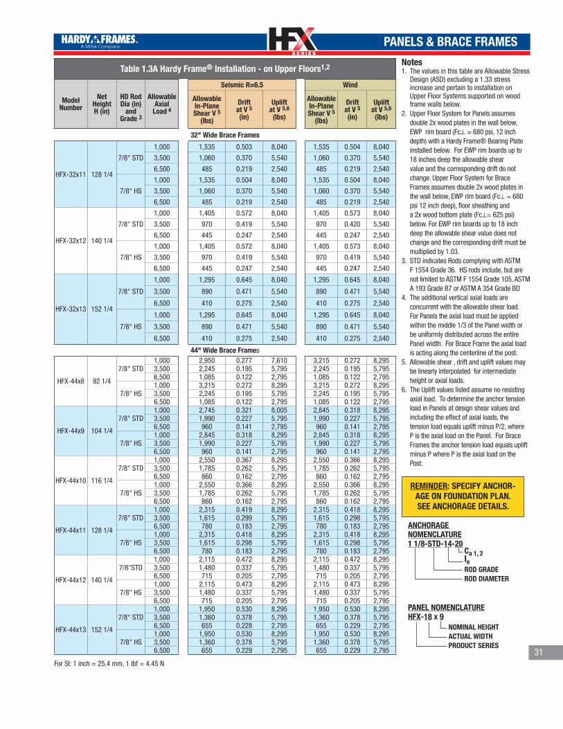
TM
TM
PANELS & BRACE FRAMES
31
Notes 1. The values in this table are Allowable Stress
Design (ASD) excluding a 1.33 stress increase and pertain to installation on Upper Floor Systems supported on wood frame walls below.
2. Upper Floor System for Panels assumes double 2x wood plates in the wall below, EWP rim board (Fc⊥ = 680 psi, 12 inch depth) with a Hardy Frame® Bearing Plate installed below. For EWP rim boards up to 18 inches deep the allowable shear value and the corresponding drift do not change. Upper Floor System for Brace Frames assumes double 2x wood plates in the wall below, EWP rim board (Fc⊥ = 680 psi 12 inch deep), floor sheathing and a 2x wood bottom plate (Fc⊥= 625 psi) below. For EWP rim boards up to 18 inch deep the allowable shear value does not change and the corresponding drift must be multiplied by 1.03.
3. STD indicates Rods complying with ASTM F 1554 Grade 36. HS rods include, but are not limited to ASTM F 1554 Grade 105, ASTM A 193 Grade B7 or ASTM A 354 Grade BD
4. The additional vertical axial loads are concurrent with the allowable shear load. For Panels the axial load must be applied within the middle 1/3 of the Panel width or be uniformly distributed across the entire Panel width. For Brace Frame the axial load is acting along the centerline of the post.
5. Allowable shear , drift and uplift values may be linearly interpolated for intermediate height or axial loads.
6. The Uplift values listed assume no resisting axial load. To determine the anchor tension load in Panels at design shear values and including the effect of axial loads, the tension load equals uplift minus P/2, where P is the axial load on the Panel. For Brace Frames the anchor tension load equals uplift minus P where P is the axial load on the Post.
REMINDER: SPECIFY ANCHOR-AGE ON FOUNDATION PLAN. SEE ANCHORAGE DETAILS.
Table 1.3A Hardy Frame® Installation - on Upper Floors1,2
Model Number
NetHeightH (in)
HD RodDia (in)
and Grade 3
AllowableAxial
Load 4
Seismic R=6.5 Wind
AllowableIn-PlaneShear V 5
(lbs)
Driftat V 5(in)
Upliftat V 5,6
(lbs)
AllowableIn-PlaneShear V 5
(lbs)
Driftat V 5(in)
Upliftat V 5,6
(lbs)
32" Wide Brace Frames
HFX-32x11 128 1/4
7/8" STD
1,000 1,535 0.503 8,040 1,535 0.504 8,040
3,500 1,060 0.370 5,540 1,060 0.370 5,540
6,500 485 0.219 2,540 485 0.219 2,540
7/8" HS
1,000 1,535 0.504 8,040 1,535 0.504 8,040
3,500 1,060 0.370 5,540 1,060 0.370 5,540
6,500 485 0.219 2,540 485 0.219 2,540
HFX-32x12 140 1/4
7/8" STD
1,000 1,405 0.572 8,040 1,405 0.573 8,040
3,500 970 0.419 5,540 970 0.420 5,540
6,500 445 0.247 2,540 445 0.247 2,540
7/8" HS
1,000 1,405 0.572 8,040 1,405 0.573 8,040
3,500 970 0.419 5,540 970 0.419 5,540
6,500 445 0.247 2,540 445 0.247 2,540
HFX-32x13 152 1/4
7/8" STD
1,000 1,295 0.645 8,040 1,295 0.645 8,040
3,500 890 0.471 5,540 890 0.471 5,540
6,500 410 0.275 2,540 410 0.275 2,540
7/8" HS
1,000 1,295 0.645 8,040 1,295 0.645 8,040
3,500 890 0.471 5,540 890 0.471 5,540
6,500 410 0.275 2,540 410 0.275 2,540
44" Wide Brace Frames
HFX-44x8 92 1/4
7/8" STD1,000 2,950 0.277 7,610 3,215 0.272 8,2953,500 2,245 0.195 5,795 2,245 0.195 5,7956,500 1,085 0.122 2,795 1,085 0.122 2,795
7/8" HS1,000 3,215 0.272 8,295 3,215 0.272 8,2953,500 2,245 0.195 5,795 2,245 0.195 5,7956,500 1,085 0.122 2,795 1,085 0.122 2,795
HFX-44x9 104 1/4
7/8" STD1,000 2,745 0.321 8,005 2,845 0.318 8,2953,500 1,990 0.227 5,795 1,990 0.227 5,7956,500 960 0.141 2,795 960 0.141 2,795
7/8" HS1,000 2,845 0.318 8,295 2,845 0.318 8,2953,500 1,990 0.227 5,795 1,990 0.227 5,7956,500 960 0.141 2,795 960 0.141 2,795
HFX-44x10 116 1/4
7/8" STD1,000 2,550 0.367 8,295 2,550 0.366 8,2953,500 1,785 0.262 5,795 1,785 0.262 5,7956,500 860 0.162 2,795 860 0.162 2,795
7/8" HS1,000 2,550 0.366 8,295 2,550 0.366 8,2953,500 1,785 0.262 5,795 1,785 0.262 5,7956,500 860 0.162 2,795 860 0.162 2,795
HFX-44x11 128 1/4
7/8" STD1,000 2,315 0.419 8,295 2,315 0.418 8,2953,500 1,615 0.299 5,795 1,615 0.298 5,7956,500 780 0.183 2,795 780 0.183 2,795
7/8" HS1,000 2,315 0.418 8,295 2,315 0.418 8,2953,500 1,615 0.298 5,795 1,615 0.298 5,7956,500 780 0.183 2,795 780 0.183 2,795
HFX-44x12 140 1/4
7/8"STD1,000 2,115 0.472 8,295 2,115 0.472 8,2953,500 1,480 0.337 5,795 1,480 0.337 5,7956,500 715 0.205 2,795 715 0.205 2,795
7/8" HS1,000 2,115 0.473 8,295 2,115 0.473 8,2953,500 1,480 0.337 5,795 1,480 0.337 5,7956,500 715 0.205 2,795 715 0.205 2,795
HFX-44x13 152 1/4
7/8" STD1,000 1,950 0.530 8,295 1,950 0.530 8,2953,500 1,360 0.378 5,795 1,360 0.378 5,7956,500 655 0.228 2,795 655 0.229 2,795
7/8" HS1,000 1,950 0.530 8,295 1,950 0.530 8,2953,500 1,360 0.378 5,795 1,360 0.378 5,7956,500 655 0.229 2,795 655 0.229 2,795
For SI: 1 inch = 25.4 mm, 1 lbf = 4.45 N
NOMINAL HEIGHTACTUAL WIDTHPRODUCT SERIES
PANEL NOMENCLATUREHFX-18 x 9
Ca 1, 2leROD GRADEROD DIAMETER
ANCHORAGE NOMENCLATURE1 1/8-STD-14-20

TM
TM
PANELS & BRACE FRAMES
HARDY FRAME PANEL WITH CFS CHANNEL®Hardy Frame® Panel
with c-fs ChannelHARDY FRAME PANEL AT C-fS PORTAL
®
Hardy Frame® Panel at c-fs Portal
HARDY FRAME PANEL BOTTOMON CONCRETE
®
HARDY FRAME PANEL BOTTOMON DOUBLE NUT
®
Hardy Frame® Panel on concrete
Hardy Frame® Panel on nuts and washers(Requires 5,000 psi
grout)
HARDY FRAME BRACE FRAMEBOTTOM ON CONCRETE
®HARDY FRAME BRACE FRAMEBOTTOM ON DOUBLE NUT
®Hardy Frame®
Brace Frame on concrete
Hardy Frame® Brace Frame
on nuts and washers
HARDY FRAME BRACE FRAMETOP WITH C-FS CHANNEL
®HARDY FRAME BRACE FRAMEC-fS PORTAL
®
HARDY FRAME BRACE FRAMEC-fS PORTAL
®Hardy Frame® Brace Frame
with c-fs Channel
Hardy Frame® Brace Frameat c-fs Portal
Hardy Frame®
Brace Frameat c-fs Portal
HFX/S Series for cold formed steel (c-fs) framing
•HFX/S Series products are manufactured to cold formed steel stud heights. Nominal 8’ heights
are 96 5/8" net, nominal 9' is 108 5/8", etc.
• Installation can be directly on concrete (moisture barrier recommended), with a c-fs channel
below, or a nut and washer for eveling or height adjustment up to ± 1/2"
•Top connections are made with 1/4" diameter self tapping screws after installing floor or roof
members above.
•Panels and Brace Frames are 3 1/2" net depth.
The new HFX-Series Brace Frame has relocated hold down bolts to be outside of the post. Hold down connections are now accessible even when wood or framing is in contact with the edge of the frame.
HARDY FRAME BRACE FRAMEBOTTOM ON RAISED FLOOR HEAD OUT
®Hardy Frame®
Brace Frameat raised floor
head out32

TM
TM
PANELS & BRACE FRAMES
Table 2.1A Hardy Frame® HFX/S Installation - on 2500 psi Concrete1,2
Model Number
NetHeightH (in)
HD RodDia (in)
and Grade 3
AllowableAxial
Load 4
Seismic R=6.5 Wind
AllowableIn-PlaneShear V 5
(lbs)
Driftat V 5 (in)
Upliftat V 5,6
(lbs)
AllowableIn-PlaneShear V 5
(lbs)
Driftat V 5(in)
Upliftat V 5,6
(lbs)
9" Wide PanelsHFX/S-9x8 96 5/8 1 1/8" STD 2,000 745 0.272 15,460 745 0.272 15,460
12" Wide Panels
HFX/S-12x8 96 5/8
1 1/8" STD1,000 1,320 0.199 17,425 1,410 0.213 19,5953,500 1,300 0.197 17,005 1,300 0.197 17,0056,500 1,160 0.176 14,320 1,160 0.176 14,320
1 1/8" HS1,000 1,410 0.214 19,595 1,410 0.214 19,5953,500 1,300 0.198 17,005 1,300 0.198 17,0056,500 1,160 0.177 14,320 1,160 0.177 14,320
HFX/S-12x9 108 5/8
1 1/8" STD1,000 1,175 0.223 17,425 1,255 0.238 19,5953,500 1,155 0.220 17,005 1,155 0.220 17,0056,500 1,035 0.196 14,325 1,035 0.196 14,325
1 1/8" HS1,000 1,255 0.240 19,595 1,255 0.240 19,5953,500 1,155 0.221 17,005 1,155 0.221 17,0056,500 1,035 0.198 14,325 1,035 0.197 14,325
HFX/S-12x10 120 5/8
1 1/8" STD1,000 1,060 0.246 17,425 1,130 0.263 19,5953,500 1,040 0.243 17,005 1,040 0.243 17,0056,500 930 0.217 14,325 930 0.217 14,325
1 1/8" HS1,000 1,130 0.265 19,595 1,130 0.265 19,5953,500 1,040 0.244 17,005 1,040 0.244 17,0056,500 930 0.218 14,325 930 0.218 14,325
18" Wide Panels
HFX/S-18x8 96 5/48
1 1/8" STD1,000 2,185 0.181 16,805
2,610 0.217 21,6203,500 2,180 0.181 16,5306,500 2,155 0.179 31,190
1 1/8" HS1,000 3,270 0.273 30,030 3,535 0.296 38,0153,500 3,210 0.268 28,260 3,385 0.284 33,7006,500 3,110 0.260 17,305 3,135 0.263 28,745
HFX/S-18x9 108 5/8
1 1/8" STD1,000 1,985 0.209 16,965
2,320 0.244 21,6203,500 1,955 0.206 16,8706,500 1,950 0.205 31,190
1 1/8" HS1,000 2,910 0.307 30,030 3,145 0.332 38,0153,500 2,855 0.301 28,260 3,015 0.318 33,7006,500 2,765 0.292 17,385 2,790 0.295 28,745
HFX/S-18x10 120 5/8
1 1/8" STD1,000 1,795 0.232 17,250
2,090 0.270 21,6203,500 1,785 0.230 17,1506,500 1,775 0.229 31,190
1 1/8" HS1,000 2,620 0.341 30,030 2,830 0.368 38,0153,500 2,570 0.334 28,260 2,715 0.353 33,7006,500 2,490 0.324 17,430 2,515 0.327 28,745
HFX/S-18x11 132 5/8
1 1/8" STD1,000
1,635 0.255 17,430 1,900 0.300 21,6203,5006,500 31,190
1 1/8" HS1,000 2,385 0.372 30,030 2,575 0.402 38,0153,500 2,340 0.365 28,260 2,470 0.385 33,7006,500 2,265 0.354 17,430 2,285 0.357 28,745
HFX/S-18x12 144 5/8
1 1/8" STD1,000
1,500 0.277 17,430 1,745 0.321 21,6203,5006,500 31,190
1 1/8" HS1,000 2,185 0.405 30,030 2,360 0.438 38,0153,500 2,145 0.397 28,260 2,265 0.419 33,7006,500 2,075 0.385 17,430 2,095 0.388 28,745
HFX/S-18x13 156 5/8
1 1/8" STD1,000
1,385 0.298 17,430 1,605 0.346 21,6203,5006,500 31,190
1 1/8" HS1,000 2,020 0.437 30,030 2,180 0.472 38,0153,500 1,980 0.429 28,260 2,090 0.452 33,7006,500 1,915 0.415 28,260 1,935 0.419 28,745
24" Wide Panels
HFX/S-24x8 96 5/8
1 1/8" STD1,000
2,960 0.131 15,200 3,800 0.168 20,4903,5006,500
1 1/8" HS1,000
4,780 0.213 27,6005,910 0.264 38,185
3,500 5,865 0.262 37,7006,500 5,795 0.258 36,880
33

TM
TM
PANELS & BRACE FRAMES
Table 2.1A Hardy Frame® HFX/S Installation - on 2500 psi Concrete1,2
Model Number
NetHeightH (in)
HD RodDia (in)
and Grade 3
AllowableAxial
Load 4
Seismic R=6.5 Wind
AllowableIn-PlaneShear V 5
(lbs)
Driftat V 5(in)
Upliftat V 5,6
(lbs)
AllowableIn-PlaneShear V 5
(lbs)
Driftat V 5(in)
Upliftat V 5,6
(lbs)
24" Wide Panels
HFX/S-24x9 108 5/8
1 1/8" STD1,000
2,715 0.151 15,7453,485 0.195 21,2503,500 3,480 0.195
6,500 3,450 0.193 21,020
1 1/8"HS1,000
4,370 0.246 28,6705,385 0.303 39,865
3,500 5,335 0.300 39,1806,500 5,250 0.295 38,055
HFX/S-24x10 120 5/8
1 1/8" STD1,000 2,505 0.172 16,215 3,180 0.218 21,6203,500 21,6106,500 2,470 0.170 15,940 3,165 0.217 21,515
1 1/8" HS1,000
4,025 0.279 29,595 4,850 0.336 39,8653,500 0.332 39,1806,500 4,725 0.327 38,055
HFX/S-24x11 132 5/8
1 1/8" STD1,000 2,330 0.193 16,620 2,880 0.237 21,6203,5006,500 2,290 0.189 16,280
1 1/8" HS1,000
3,730 0.308 30,4204,410 0.365 39,865
3,500 4,370 0.362 39,1806,500 4,300 0.356 38,055
HFX/S-24x12 144 5/8
1 1/8" STD1,000 2,175 0.213 16,975 2,640 0.259 21,6203,500 2,140 0.209 16,655 2,640 0.259 21,6206,500 2,130 0.208 16,560 2,640 0.259 21,620
1 1/8"HS1,000
3,410 0.334 30,2854,045 0.397 39,865
3,500 4,005 0.393 39,1806,500 3,940 0.387 38,055
HFX/S-24x13 156 5/8
1 1/8" STD1,000 2,040 0.234 17,290 2,440 0.279 21,6203,500 2,000 0.230 16,905 2,440 0.279 21,6206,500 1,990 0.229 16,805 2,440 0.279 21,620
1 1/8" HS1,000
3,140 0.360 30,1603,735 0.428 39,865
3,500 3,700 0.424 39,1806,500 3,640 0.417 38,055
32" Wide Brace Frames
HFX/S-32x8 96 5/8
7/8" STD1,000 2,155 0.126 8,505 2,695 0.158 10,6303,500 2,060 0.121 8,130 2,060 0.120 8,1306,500 1,300 0.076 5,130 1,300 0.076 5,130
7/8" HS1,000 2,865 0.168 11,295 2,865 0.168 11,2953,500 2,230 0.131 8,795 2,230 0.131 8,7956,500 1,470 0.086 5,795 1,470 0.086 5,795
HFX/S-32x9 108 5/8
7/8"STD1,000 1,990 0.165 8,825 2,400 0.199 10,6303,500 1,835 0.152 8,130 1,835 0.152 8,1306,500 1,155 0.096 5,130 1,155 0.096 5,130
7/8" HS1,000 2,550 0.211 11,295 2,550 0.211 11,2953,500 1,985 0.164 8,795 1,985 0.164 8,7956,500 1,305 0.108 5,795 1,305 0.108 5,795
HFX/S-32x10 120 5/8
7/8" STD1,000 1,850 0.209 9,100 2,160 0.245 10,6303,500 1,650 0.187 8,130 1,650 0.187 8,1306,500 1,040 0.118 5,130 1,040 0.118 5,130
7/8" HS1,000 2,295 0.260 11,295 2,295 0.260 11,2953,500 1,785 0.202 8,795 1,785 0.202 8,7956,500 1,175 0.133 5,795 1,175 0.133 5,795
HFX/S-32x11 132 5/8
7/8" STD1,000 1,725 0.259 9,335 1,965 0.296 10,6303,500 1,500 0.226 8,130 1,500 0.226 8,1306,500 950 0.143 5,130 950 0.143 5,130
7/8" HS1,000 2,085 0.314 11,295 2,085 0.314 11,2953,500 1,625 0.245 8,795 1,625 0.245 8,7956,500 1,070 0.161 5,795 1,070 0.161 5,795
HFX/S-32x12 144 5/8
7/8" STD1,000 1,615 0.316 9,545 1,800 0.353 10,6303,500 1,375 0.269 8,130 1,375 0.270 8,1306,500 870 0.170 5,130 870 0.170 5,130
7/8" HS1,000 1,915 0.374 11,295 1,915 0.374 11,2953,500 1,490 0.291 8,795 1,490 0.291 8,7956,500 980 0.192 5,795 980 0.192 5,795
34
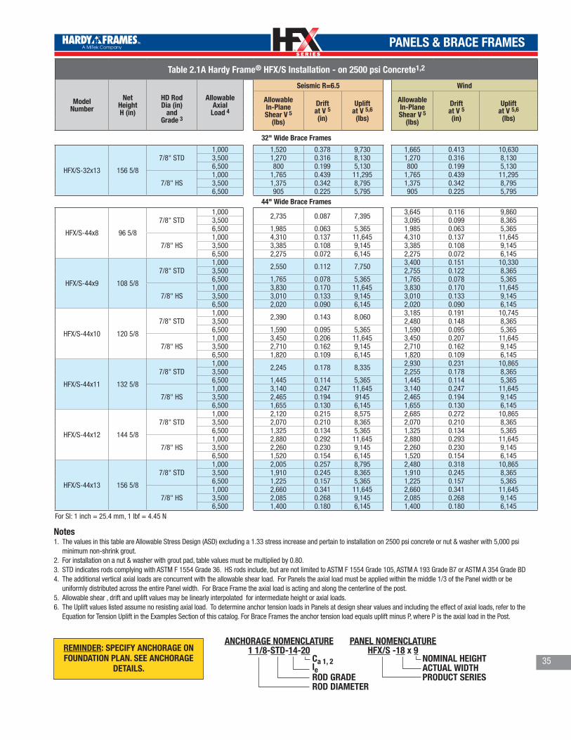
TM
TM
PANELS & BRACE FRAMES
35
Table 2.1A Hardy Frame® HFX/S Installation - on 2500 psi Concrete1,2
Model Number
NetHeightH (in)
HD RodDia (in)
and Grade 3
AllowableAxial
Load 4
Seismic R=6.5 Wind
AllowableIn-PlaneShear V 5
(lbs)
Driftat V 5(in)
Upliftat V 5,6
(lbs)
AllowableIn-PlaneShear V 5
(lbs)
Driftat V 5(in)
Upliftat V 5,6
(lbs)
32" Wide Brace Frames
HFX/S-32x13 156 5/8
7/8" STD1,000 1,520 0.378 9,730 1,665 0.413 10,6303,500 1,270 0.316 8,130 1,270 0.316 8,1306,500 800 0.199 5,130 800 0.199 5,130
7/8" HS1,000 1,765 0.439 11,295 1,765 0.439 11,2953,500 1,375 0.342 8,795 1,375 0.342 8,7956,500 905 0.225 5,795 905 0.225 5,795
44" Wide Brace Frames
HFX/S-44x8 96 5/8
7/8" STD1,000 2,735 0.087 7,395 3,645 0.116 9,8603,500 3,095 0.099 8,3656,500 1,985 0.063 5,365 1,985 0.063 5,365
7/8" HS1,000 4,310 0.137 11,645 4,310 0.137 11,6453,500 3,385 0.108 9,145 3,385 0.108 9,1456,500 2,275 0.072 6,145 2,275 0.072 6,145
HFX/S-44x9 108 5/8
7/8" STD1,000 2,550 0.112 7,750 3,400 0.151 10,3303,500 2,755 0.122 8,3656,500 1,765 0.078 5,365 1,765 0.078 5,365
7/8" HS1,000 3,830 0.170 11,645 3,830 0.170 11,6453,500 3,010 0.133 9,145 3,010 0.133 9,1456,500 2,020 0.090 6,145 2,020 0.090 6,145
HFX/S-44x10 120 5/8
7/8" STD1,000 2,390 0.143 8,060 3,185 0.191 10,7453,500 2,480 0.148 8,3656,500 1,590 0.095 5,365 1,590 0.095 5,365
7/8" HS1,000 3,450 0.206 11,645 3,450 0.207 11,6453,500 2,710 0.162 9,145 2,710 0.162 9,1456,500 1,820 0.109 6,145 1,820 0.109 6,145
HFX/S-44x11 132 5/8
7/8" STD1,000 2,245 0.178 8,335 2,930 0.231 10,8653,500 2,255 0.178 8,3656,500 1,445 0.114 5,365 1,445 0.114 5,365
7/8" HS1,000 3,140 0.247 11,645 3,140 0.247 11,6453,500 2,465 0.194 9145 2,465 0.194 9,1456,500 1,655 0.130 6,145 1,655 0.130 6,145
HFX/S-44x12 144 5/8
7/8" STD1,000 2,120 0.215 8,575 2,685 0.272 10,8653,500 2,070 0.210 8,365 2,070 0.210 8,3656,500 1,325 0.134 5,365 1,325 0.134 5,365
7/8" HS1,000 2,880 0.292 11,645 2,880 0.293 11,6453,500 2,260 0.230 9,145 2,260 0.230 9,1456,500 1,520 0.154 6,145 1,520 0.154 6,145
HFX/S-44x13 156 5/8
7/8" STD1,000 2,005 0.257 8,795 2,480 0.318 10,8653,500 1,910 0.245 8,365 1,910 0.245 8,3656,500 1,225 0.157 5,365 1,225 0.157 5,365
7/8" HS1,000 2,660 0.341 11,645 2,660 0.341 11,6453,500 2,085 0.268 9,145 2,085 0.268 9,1456,500 1,400 0.180 6,145 1,400 0.180 6,145
For SI: 1 inch = 25.4 mm, 1 lbf = 4.45 N
Notes 1. The values in this table are Allowable Stress Design (ASD) excluding a 1.33 stress increase and pertain to installation on 2500 psi concrete or nut & washer with 5,000 psi
minimum non-shrink grout.2. For installation on a nut & washer with grout pad, table values must be multiplied by 0.80.3. STD indicates rods complying with ASTM F 1554 Grade 36. HS rods include, but are not limited to ASTM F 1554 Grade 105, ASTM A 193 Grade B7 or ASTM A 354 Grade BD4. The additional vertical axial loads are concurrent with the allowable shear load. For Panels the axial load must be applied within the middle 1/3 of the Panel width or be
uniformly distributed across the entire Panel width. For Brace Frame the axial load is acting and along the centerline of the post. 5. Allowable shear , drift and uplift values may be linearly interpolated for intermediate height or axial loads. 6. The Uplift values listed assume no resisting axial load. To determine anchor tension loads in Panels at design shear values and including the effect of axial loads, refer to the
Equation for Tension Uplift in the Examples Section of this catalog. For Brace Frames the anchor tension load equals uplift minus P, where P is the axial load in the Post.
NOMINAL HEIGHTACTUAL WIDTHPRODUCT SERIES
PANEL NOMENCLATUREHFX/S -18 x 9
Ca 1, 2leROD GRADEROD DIAMETER
ANCHORAGE NOMENCLATURE1 1/8-STD-14-20REMINDER: SPECIFY ANCHORAGE ON
FOUNDATION PLAN. SEE ANCHORAGE DETAILS.
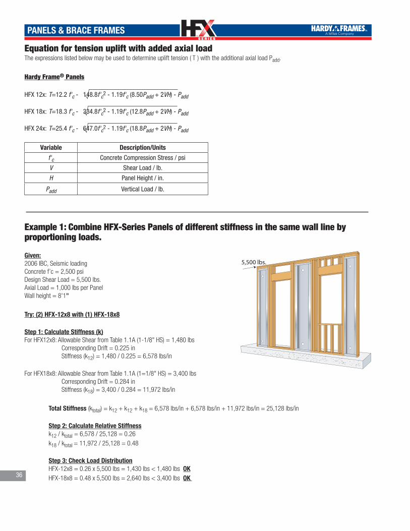
TM
TM
PANELS & BRACE FRAMES
Equation for tension uplift with added axial loadThe expressions listed below may be used to determine uplift tension ( T ) with the additional axial load Padd.
Hardy Frame® Panels
HFX 12x: T=12.2 f'c - 148.8f'c2 - 1.19f'c (8.50Padd + 2VH) - Padd
HFX 18x: T=18.3 f'c - 334.8f'c2 - 1.19f'c (12.8Padd + 2VH) - Padd
HFX 24x: T=25.4 f'c - 647.0f'c2 - 1.19f'c (18.8Padd + 2VH) - Padd
Variable Description/Units
f'c Concrete Compression Stress / psi
V Shear Load / lb.
H Panel Height / in.
Padd Vertical Load / lb.
Example 1: Combine HFX-Series Panels of different stiffness in the same wall line by proportioning loads.
Given:2006 IBC, Seismic loadingConcrete f’c = 2,500 psiDesign Shear Load = 5,500 lbs.Axial Load = 1,000 lbs per PanelWall height = 8'1"
Try: (2) HFX-12x8 with (1) HFX-18x8
Step 1: Calculate Stiffness (k)For HFX12x8: Allowable Shear from Table 1.1A (1-1/8" HS) = 1,480 lbs Corresponding Drift = 0.225 in Stiffness (k12) = 1,480 / 0.225 = 6,578 lbs/in
For HFX18x8: Allowable Shear from Table 1.1A (1=1/8" HS) = 3,400 lbs Corresponding Drift = 0.284 in Stiffness (k18) = 3,400 / 0.284 = 11,972 lbs/in
Total Stiffness (ktotal) = k12 + k12 + k18 = 6,578 lbs/in + 6,578 lbs/in + 11,972 lbs/in = 25,128 lbs/in
Step 2: Calculate Relative Stiffness k12 / ktotal = 6,578 / 25,128 = 0.26 k18 / ktotal = 11,972 / 25,128 = 0.48
Step 3: Check Load Distribution HFX-12x8 = 0.26 x 5,500 lbs = 1,430 lbs < 1,480 lbs OK HFX-18x8 = 0.48 x 5,500 lbs = 2,640 lbs < 3,400 lbs OK
5,500 lbs.
36

TM
TM
PANELS & BRACE FRAMES
Example 2: Designing for stacked Hardy Frame® Panels or Brace Frames
When designing for Panels to be stacked vertically in direct alignment as shown, the cumulative shear, moment and overturning forces of the system must be checked. The following example illustrates our recommended analysis for checking allowable loads.
Given2006 IBC, Wind Loading, Concrete f'c= 2,500 psi1st Floor Wall Height: 9' 1"Floor System Depth: 1' 0"2nd Floor Wall Height: 8'1"Shear Load at 1st Floor (V1): 1,000 lbs WindShear Load at 2nd Floor (V2): 1,000 lbs WIndShear Load at Foundation (Vbase): 2,000 lbs Wind (1,000 lbs + 1,000 lbs)No Additional Vertical Loads
Step 1. Select HFX-18x8 (1-1/8" STD Rods) at Second Floor : Allowable WInd Shear from Table 1.3A = 2,740 lbsHFX-18x9 (1-1/8" HS Rods) at First Floor : Allowable Wind Shear from Table 1.1A = 3,275 lbs
Step 2. Check ShearA) Shear at the Second Floor (V2)HFX-18x8 Allowable Shear = 2,740 lbs > 1,000 lbs OKB) Shear at the Foundation (Vbase) HFX-18x9 Allowable Shear = 3,275 lbs > 2,000 lbs OK
Step 3. Check MomentA) Calculate Cumulative Overturning Moment of the Stacked PanelsSecond Floor @ 18' 2" = 218 in x 1,000 lbs = 218,000 in-lbs First Floor @ 9' 1" = 109 in x 1,000 lbs = 109,000 in-lbs Total Calculated Overturning Moment = 327,000 in-lbs.
B) Calculate Moment Capacity of the Stacked PanelsUse the First Floor Panel Moment Capacity as the Capacity of the Stacked PanelsAllowable Moment = Allowable Shear x Panel Height = 3,275 lbs x 104.25in = 341,419 in-lbs.
C) Check Cumulative Overturning Moment341,419 in-lbs (Capacity) > 327,000 in-lbs (Cumulative moment) OK
Step 4. Foundation Anchor Tension
Calculated Overturning Moment 327,000 in-lbs Allowable Moment
x Uplift at Allowable Moment. = 341,419 in-lbs
x 38,015 lbs = 36,410 lbs
1,000 lbs
1,000 lbs
9’-1”
12” Floor
8’-1”
37
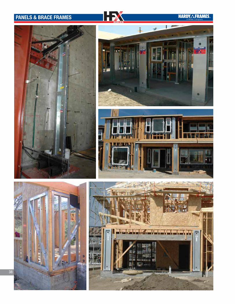
TM
TM
PANELS & BRACE FRAMES
38
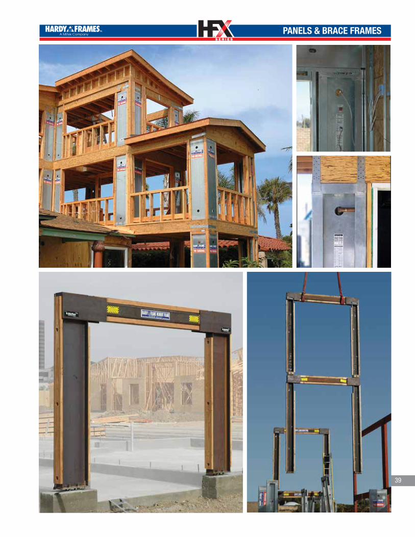
TM
TM
PANELS & BRACE FRAMES
39

TM
TM
ACCESSORIES
Hardy Frame® Post
The Hardy Frame HFP-Series and HFP/S-Series Post are now available in 7/8 inch diameter hold down rods for connecting to Brace Frames above and in 1-1/8 inch diameter for connecting to Panels above.
Tables provide tensile values for standard grade (STD) and for High Strength (HS) hold down rods. Be sure to include the embed callout on the foundation plan The access holes to both the bottom and the top hold down rods are now located on the same edge of the post.
All Posts are 3 1/2" x 3 1/2" square and are fabricated from 12 gage steel. Custom heights up to the maximum listed in the table are available.
Hardy Frame® Panel to two Hardy Frame®
Posts below
Hardy Frame® Brace Frame
to two Hardy Frame® Posts below
HARDY FRAME PANEL BOTTOM2 POSTS
®
HARDY FRAME BRACE FRAMEBOTTOM 2 POSTS
® HARDY FRAME POST BOTTOMON DOUBLE NUT
®Hardy Frame® Post on nut and washer (requires 5,000 psi non-shrink grout)
ModelNumber
NetHeight (in)
Hold DownDiameter (in)
Allowable Compression 2,3 (lbs)
Allowable Tensionby Hold Down Grade
STD 4 (lbs) HS 5 (lbs)
HFP-Series
HFP8-7/8 92 1/4 7/8 26,645 13,500 27,100HFP8-1 1/8 92 1/4 1 1/8 22,400 36,100HFP9-7/8 104 1/4 7/8 24,170 13,500 27,100
HFP9-1 1/8 104 1/4 1 1/8 22,400 36,100HFP10-7/8 116 1/4 7/8 21,255 13,500 27,100
HFP10-1 1/8 116 1/4 1 1/8 22,400 36,100HFP11-7/8 128 1/4 7/8 18,765 13,500 27,100
HFP11-1 1/8 128 1/4 1 1/8 22,400 36,100HFP12-7/8 140 1/4 7/8 16,645 13,500 27,100
HFP12-1 1/8 140 1/4 1 1/8 22,400 36,100HFP13-7/8 152 1/4 7/8 14,090 13,500 27,100
HFP13-1 1/8 152 1/4 1 1/8 22,400 36,100
HFP/S-Series
HFP/S8-7/8 96 5/8 7/8 25,745 13,500 27,100HFP/S8-1 1/8 96 5/8 1 1/8 22,400 36,100HFP/S9-7/8 108 5/8 7/8 23,105 13,500 27,100
HFP/S9-1 1/8 108 5/8 1 1/8 22,400 36,100HFP/S10-7/8 120 5/8 7/8 20,350 13,500 27,100
HFP/S10-1 1/8 120 5/8 1 1/8 22,400 36,100HFP/S11-7/8 132 5/8 7/8 17,990 13,500 27,100
HFP/S11-1 1/8 132 5/8 1 1/8 22,400 36,100HFP/S12-7/8 144 5/8 7/8 15,715 13,500 27,100
HFP/S12-1 1/8 144 5/8 1 1/8 22,400 36,100HFP/S13-7/8 156 5/8 7/8 13,160 13,500 27,100
HFP/S13-1 1/8 156 5/8 1 1/8 22,400 36,100
For SI: 1 inch = 25.4 mm, 1 lbf = 4.45 N
1. The values in this table are Allow-able Stress Design (ASD), exclude a 1.33 stress increase and assume installations on a rigid base, or a nut and washer with 5,000 psi minimum compressive strength non-shrink grout
2. The maximum allowable design com-pression is governed by the allowable compression of the supporting mate-rial below and based on the Post’s bearing area of 12.25 square inches. Common supports include: A) Wood with 625 psi allowable compression perpendicular to grain = 7,656 lbs. B) Wood with 680 psi allowable compression perpendicular to grain = 8,330 lbs. C) 2500 psi Concrete = 10,412 lbs. D) 3000 psi Concrete = 12,495 lbs. E) 4000 psi Concrete = 16,660 lbs.
3. The Building Design Professional is permitted to design bearing plates to reduce bearing stress.
4. STD Hold Down rods must comply with ASTM F 1554 Grade 36. HS Hold Down rods must comply with a high strength steel specification and have an adequate ASD capacity to resist the tabulated uplift values. High Strength rods include but are not limited to ASTM F 1554 Grade 105, ASTM A 193 Grade B7 and ASTM A 354 Grade BD.
40
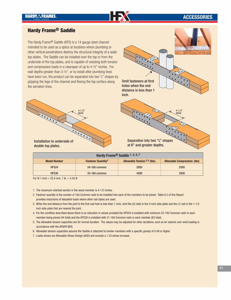
TM
TM
ACCESSORIES
Hardy Frame® Saddle 1, 3, 4, 7
Model Number Fastener Quantity2 Allowable Tension 5, 6 (lbs) Allowable Compression (lbs)
HFS24 24-16d common 2950 2500
HFS36 32-16d common 4280 2500
Hardy Frame® Saddle The Hardy Frame® Saddle (HFS) is a 14 gauge steel channel intended to be used as a splice at locations where plumbing or other vertical penetrations destroy the structural integrity of a walls top plates. The Saddle can be installed over the top or from the underside of the top plates, and is capable of resisting both tension and compression loads in a clearspan of up to 4-½" inches. For wall depths greater than 3-½", or to install after plumbing lines have been run, the product can be separated into two “L” shapes by gripping the legs of the channel and flexing the top surface along the serration lines.
Installation to underside of double top plates.
Separation into two “L” shapes at 6” and greater depths.
Omit fasteners at first holes when the end distance is less than 1 inch.
1. The maximum notched section in the wood member is 4-1/2 inches.
2. Fastener quantity is the number of 16d Common nails to be installed into each of the members to be joined. Table 6.2 of this Report
provides reductions of tabulated loads where other nail styles are used.
3. When the end distance from the joint to the first nail hole is less than 1-inch, omit the (2) nails in the 3-inch side-plate and the (1) nail in the 1-1/2
inch side-plate that are nearest the joint.
4. For the condition described above there is no reduction in values provided the HFS24 is installed with minimum 22-16d Common nails in each
member being joined (44 total) and the HFS36 is installed with 31-16d Common nails in each member (62 total).
5. The allowable tension capacities are for normal duration. The values may be adjusted for other durations, such as for seismic and wind loading in
accordance with the AF&PA NDS.
6. Allowable tension capacities assume the Saddle is attached to lumber members with a specific gravity of 0.49 or higher
7. Loads shown are Allowable Stress Design (ASD) and exclude a 1.33 stress increase.
For SI 1 inch = 25.4 mm, 1 lb. = 4.45 N
41

TM
TM
42
ACCESSORIES
Hardy Frame® HFX-Series Template Kit (HFXTK)
Hardy Frame® HFX-Series Template (HFXT)•Assures proper bolt spacing and alignment
•16 gage material supports weight of embed bolts
•Variety of applications
Panel Kit at Slab Brace Frame Kitat Interior Footing
Panel Kit at Curb
Hardy Frame® HFX-Series Template Kit Components
Kit Model Number Template (1 ea) Bolt Brace (1 ea)
Panels Brace Frames
Hold Down Anchor Assembly
1-1/8 STD 1-1/8 HS 7/8 STD 7/8 HSHFXTK9 HFXT9 HFXBB9 2HFXTK12 HFXT12 HFXBB12 2
HFXTK-HS12 HFXT12 HFXBB12 2 HFXTK18 HFXT18 HFXBB18 2
HFXTK-HS18 HFXT18 HFXBB18 2 HFXTK24 HFXT24 HFXBB24 2
HFXTK-HS24 HFXT24 HFXBB24 2 HFXTK32 HFXT32 NA 2
HFXTK-HS32 HFXT32 NA 2HFXTK44 HFXT44 NA 2
HFXTK-HS44 HFXT44 NA 2
Hardy FrameBolt Brace(HFXBB)
Hardy Frame Bolt Brace
Grade 8 Hex Nut
Standard Grade Hex Nut minimum
Hardened Round WasherALT: two SAE WashersALT: two Flat-Round Washers
Hold Down Anchor“STD” = ASTM F1554 Grade 36 •Requires HFXBB (Bolt Brace) or Plate Washers @ embed end
“HS” = ASTM A193 Grade B7 •Requires 1/2 x 3 x 3 Plate Washers @ embed end, HFXBB (Bolt Brace) optional •Do not attempt to bend HS rods
1/2 x 3 x 3 Plate Washer
HFXBB - Bolt Brace
Hold Down Anchor Assemblies:1-1/8 STD = 1-1/8 x 32" ASTM F1554 Grade-36 all thread with(1)-Hardened Round Washer & (3) Grade 8 Hex Nuts.1-1/8 HS = 1-1/8 x 38" ASTM A193 Grade-B7 all thread with (1) Hardened Round Washer, (1) 1/2x3x3 ASTM A36 Plate Washer & (3) Grade-8 Hex Nuts7/8 STD = 7/8 x 30" ASTM F1554 Grade-36 all thread with(1) Hardened Round Washer (1) 1/2x3x3 ASTM A36 Plate Washer & (3) Grade 8 Hex Nuts.7/8 HS = 7/8 x 31" ASTM A193 Grade-B7 all thread with (1) Hardened Round Washer, (1) 1/2x3x3 ASTM A36 Plate Washer & (3) Grade-8 Hex Nuts For other rod lengths contact Hardy Frames Inc.1) All Thread length = length of embed (le) + 12” (formboard) + 6”(Kit assembly + height above concrete) For Raised Floor installations adjust the all thread length or extend length with a Grade 8 Coupling nut2) The Hardened Round Washers for connecting the Panel base may be substituted with two SAE or two Round-Flat Washers 3) STD assemblies require a Hardy Frame® Bolt Brace (Minimum) double nutted at the embed end or 1/2x3x3 ASTM A36 Plate Washer4) HS assemblies require 1/2x3x3 ASTM A36 Plate Washer (Minimum) and the Hardy Frame® Bolt Brace is optional5) HS all thread rods provided by Hardy Frames, Inc. are stamped on both ends HF
B7
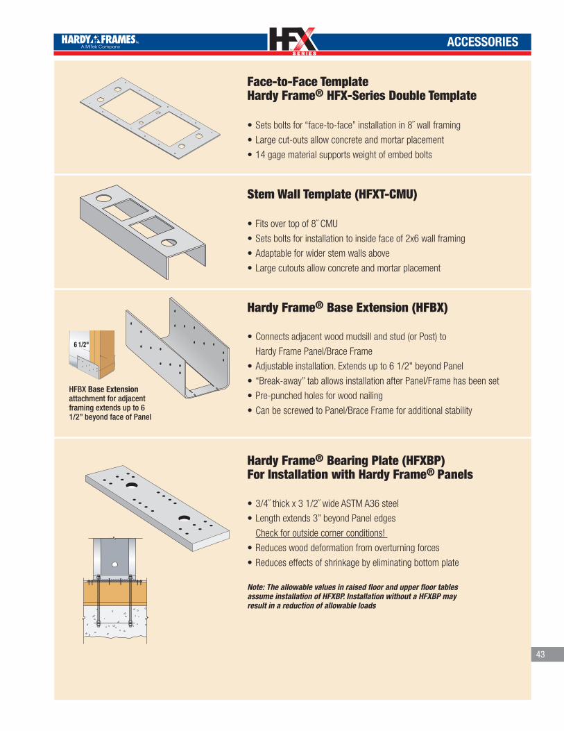
TM
TM
ACCESSORIES
Face-to-Face Template Hardy Frame® HFX-Series Double Template
•Sets bolts for “face-to-face” installation in 8˝ wall framing
•Large cut-outs allow concrete and mortar placement
•14 gage material supports weight of embed bolts
Stem Wall Template (HFXT-CMU)
•Fits over top of 8˝ CMU
•Sets bolts for installation to inside face of 2x6 wall framing
•Adaptable for wider stem walls above
•Large cutouts allow concrete and mortar placement
Hardy Frame® Base Extension (HFBX)
•Connects adjacent wood mudsill and stud (or Post) to
Hardy Frame Panel/Brace Frame
•Adjustable installation. Extends up to 6 1/2" beyond Panel
•“Break-away” tab allows installation after Panel/Frame has been set
•Pre-punched holes for wood nailing
•Can be screwed to Panel/Brace Frame for additional stability
Hardy Frame® Bearing Plate (HFXBP)For Installation with Hardy Frame® Panels
•3/4˝ thick x 3 1/2˝ wide ASTM A36 steel
•Length extends 3” beyond Panel edges
Check for outside corner conditions!
•Reduces wood deformation from overturning forces
•Reduces effects of shrinkage by eliminating bottom plate
Note: The allowable values in raised floor and upper floor tables assume installation of HFXBP. Installation without a HFXBP may result in a reduction of allowable loads
HARDY FRAME PANEL BOTTOMON RAISED FLOOR
®
43
HFBX Base Extensionattachment for adjacent framing extends up to 6 1/2” beyond face of Panel
6 1/2"
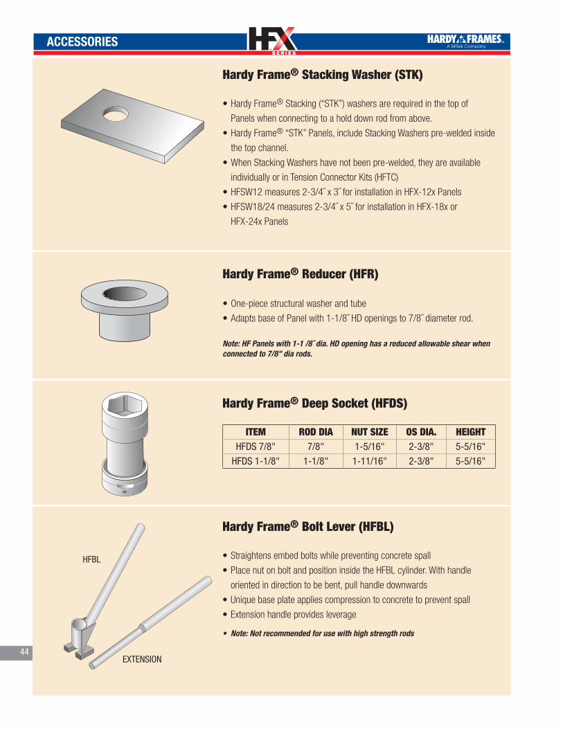
TM
TM
44
ACCESSORIES
Hardy Frame® Reducer (HFR)
•One-piece structural washer and tube
•Adapts base of Panel with 1-1/8˝ HD openings to 7/8˝ diameter rod.
Note: HF Panels with 1-1 /8˝ dia. HD opening has a reduced allowable shear when connected to 7/8” dia rods.
Hardy Frame® Bolt Lever (HFBL)
•Straightens embed bolts while preventing concrete spall
•Place nut on bolt and position inside the HFBL cylinder. With handle
oriented in direction to be bent, pull handle downwards
•Unique base plate applies compression to concrete to prevent spall
•Extension handle provides leverage
• Note: Not recommended for use with high strength rods
ITEM ROD DIA NUT SIZE OS DIA. HEIGHTHFDS 7/8" 7/8" 1-5/16" 2-3/8" 5-5/16"
HFDS 1-1/8" 1-1/8" 1-11/16" 2-3/8" 5-5/16"
HFBL
EXTENSION
Hardy Frame® Deep Socket (HFDS)
Hardy Frame® Stacking Washer (STK)
•Hardy Frame® Stacking (“STK”) washers are required in the top of
Panels when connecting to a hold down rod from above.
•Hardy Frame® “STK” Panels, include Stacking Washers pre-welded inside
the top channel.
•When Stacking Washers have not been pre-welded, they are available
individually or in Tension Connector Kits (HFTC)
•HFSW12 measures 2-3/4˝ x 3˝ for installation in HFX-12x Panels
•HFSW18/24 measures 2-3/4˝ x 5˝ for installation in HFX-18x or
HFX-24x Panels
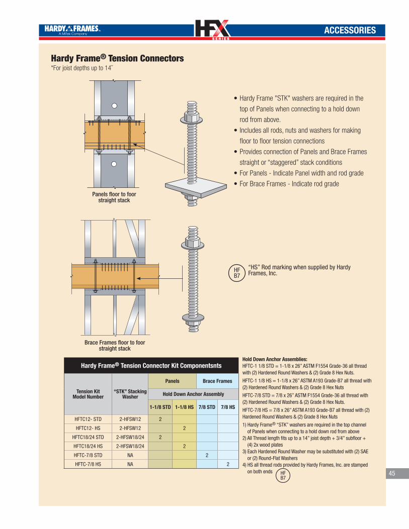
TM
TM
ACCESSORIES
HARDY FRAME PANEL BOTTOMON MULTI STORY
®
HARDY FRAME BRACE FRAMEBOTTOM ON MULTI STORY
®
Hardy Frame® Tension Connectors*For joist depths up to 14˝
Panels floor to foorstraight stack
“HS” Rod marking when supplied by Hardy Frames, Inc.HF
B7
Brace Frames floor to foorstraight stack
•Hardy Frame "STK" washers are required in the
top of Panels when connecting to a hold down
rod from above.
• Includes all rods, nuts and washers for making
floor to floor tension connections
•Provides connection of Panels and Brace Frames
straight or “staggered” stack conditions
•For Panels - Indicate Panel width and rod grade
•For Brace Frames - Indicate rod grade
Hardy Frame® Tension Connector Kit Componentsnts
Tension Kit Model Number
“STK” Stacking Washer
Panels Brace Frames
Hold Down Anchor Assembly
1-1/8 STD 1-1/8 HS 7/8 STD 7/8 HS
HFTC12- STD 2-HFSW12 2
HFTC12- HS 2-HFSW12 2
HFTC18/24 STD 2-HFSW18/24 2
HFTC18/24 HS 2-HFSW18/24 2
HFTC-7/8 STD NA 2
HFTC-7/8 HS NA 2
Hold Down Anchor Assemblies:HFTC-1 1/8 STD = 1-1/8 x 26” ASTM F1554 Grade-36 all thread with (2) Hardened Round Washers & (2) Grade 8 Hex Nuts.
HFTC-1 1/8 HS = 1-1/8 x 26” ASTM A193 Grade-B7 all thread with (2) Hardened Round Washers & (2) Grade 8 Hex Nuts
HFTC-7/8 STD = 7/8 x 26” ASTM F1554 Grade-36 all thread with (2) Hardened Round Washers & (2) Grade 8 Hex Nuts.
HFTC-7/8 HS = 7/8 x 26” ASTM A193 Grade-B7 all thread with (2) Hardened Round Washers & (2) Grade 8 Hex Nuts
1) Hardy Frame® “STK” washers are required in the top channel of Panels when connecting to a hold down rod from above2) All Thread length fits up to a 14” joist depth + 3/4” subfloor + (4) 2x wood plates3) Each Hardened Round Washer may be substituted with (2) SAE or (2) Round-Flat Washers 4) HS all thread rods provided by Hardy Frames, Inc. are stamped on both ends HF
B745
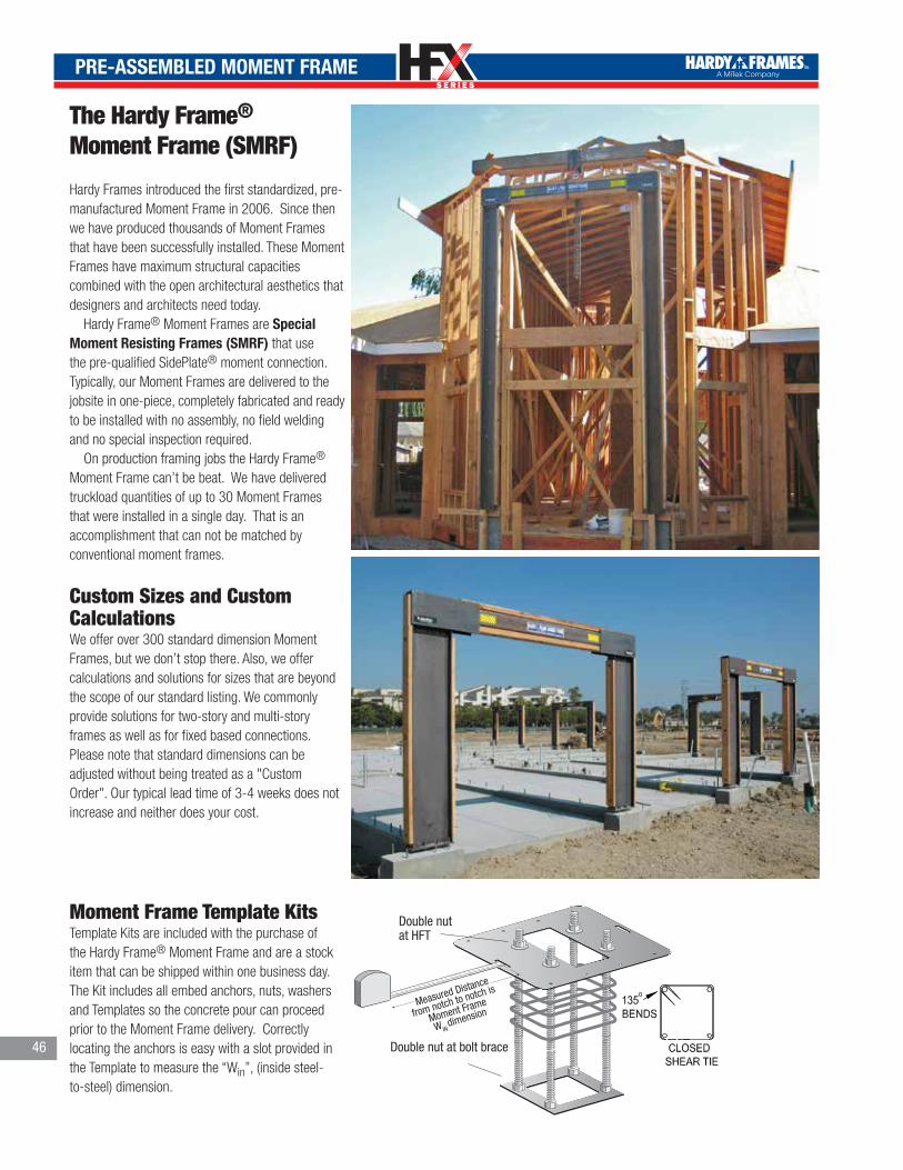
TM
TM
PRE-ASSEMBLED MOMENT FRAME
The Hardy Frame® Moment Frame (SMRF)
Hardy Frames introduced the first standardized, pre-manufactured Moment Frame in 2006. Since then we have produced thousands of Moment Frames that have been successfully installed. These Moment Frames have maximum structural capacities combined with the open architectural aesthetics that designers and architects need today. Hardy Frame® Moment Frames are Special Moment Resisting Frames (SMRF) that use the pre-qualified SidePlate® moment connection. Typically, our Moment Frames are delivered to the jobsite in one-piece, completely fabricated and ready to be installed with no assembly, no field welding and no special inspection required. On production framing jobs the Hardy Frame® Moment Frame can’t be beat. We have delivered truckload quantities of up to 30 Moment Frames that were installed in a single day. That is an accomplishment that can not be matched by conventional moment frames.
Custom Sizes and Custom CalculationsWe offer over 300 standard dimension Moment Frames, but we don’t stop there. Also, we offer calculations and solutions for sizes that are beyond the scope of our standard listing. We commonly provide solutions for two-story and multi-story frames as well as for fixed based connections. Please note that standard dimensions can be adjusted without being treated as a "Custom Order". Our typical lead time of 3-4 weeks does not increase and neither does your cost.
Moment Frame Template KitsTemplate Kits are included with the purchase of the Hardy Frame® Moment Frame and are a stock item that can be shipped within one business day. The Kit includes all embed anchors, nuts, washers and Templates so the concrete pour can proceed prior to the Moment Frame delivery. Correctly locating the anchors is easy with a slot provided in the Template to measure the “Win”, (inside steel-to-steel) dimension.
46
Measured Distance
from notch to notch is
Moment Frame
W IN dimension
Double nutat HFT
Double nut at bolt brace

TM
TM
47
Z4 PRODUCTS
The CT (Compression/Tension) Tie:
•Designed and tested to resist compression and tension loads
•Highest allowable load in the industry of over 60 kips
•Allows for accurate and reliable installation
• Ideal for tilt-up building designs•Applicable for retro-fit or new construction
• ICC-ES and City of LA Recognized
The T2 Concentric Hold-down:
•The strongest code listed concentric hold-down
•Can be used in a “sandwich” for a concentric connection
•Allows for higher load capacity with less hardware
•Highest allowable load in the industry of over 60 kips
•Allows for accurate and reliable installation Ideal for retro-fit or new construction
• ICC-ES and LA City Recognized
•The most economical and comprehensive continuous tie-down solution•Easiest, most accurate, and quickest system to install•Utilizes the least number of components•Color coded and stamped components for easy identification•The only system using a perpetual wood shrinkage compensation device•No special tools or activation devices required•Full engineering support from design to submittal package
• ICC-ES and LA City recognized
CT
T2
The Quick-Connect Continuous Tie-Down System

TM
TM
DETAILS
48
®
HARDY FRAME HFX-SERIES PANEL ON FOUNDATION
THREADED ROD HOLD DOWN BOLT (PER PLAN)
MOISTURE BARRIER RECOMMENDED (USE #15 FELT, OR EQUIVALENT)
®
Hardy Frame BOLT BRACE (HFXBB) MAY BE INSTALLED WITHOUT 1/2"x3"x3" PLATE WASHERS WHEN ASTM F1554 GR 36 THREADED ROD IS SPECIFIED.
1HFX1
HARDENDED ROUND, (2)SAE OR (2) ROUND-FLATWASHERS AND GRADE 8HEX NUT
FOUNDATION DESIGN BY BUILDING DESIGN PROFESSIONAL
KING STUDRECOMMENDED
TRIMMER RECOMMENDED
OPTIONALSOFFIT
FURR TOP AS NECESSARY
GARAGE FRONT PORTAL
BALLOON
PER PLAN
PANEL
PER PLAN
PER PLAN
PER PLAN
PER PLAN
PER PLAN
PER PLAN
PER PLAN
GARAGE FRONTFULL HEIGHT PANEL
2x (MIN) KING STUDRECOMMENDED
TRIMMER PER PLANS
3" Minimum
MOISTURE BARRIER RECOMMENDED (USE #15 FELT, OR EQUIVALENT)
®Hardy Frame BOLT BRACE (HFXBB) MAY BE INSTALLED WITHOUT 1/2"x3"x3" PLATE WASHERS WHEN ASTM F1554 GR 36 THREADED ROD IS SPECIFIED.
HARDY FRAME HFX-SERIES PANEL ®
FOUNDATION DESIGN BY BUILDING DESIGN PROFESSIONAL
ON FOUNDATION AT RAISED FLOOR HEAD-OUT 1
HFX3
HARDENDED ROUND, (2)SAE OR (2) ROUND-FLATWASHERS AND GRADE 8HEX NUT
OPTIONAL SOFFIT OR HEADER
TABLE 1.1 VALUESDETAIL 1-HFX1 ON CONCRETEDETAIL 2-HFX1 ON NUT & WASHER
FOR FACE TO FACE BASE CONNECTION SEEDETAIL 4-HFX1 ON CONCRETE
SPECIFY ANCHORAGEON FOUNDATION PLANPER ANCHORAGE NOMENCLATURE
FOR FACE TO FACE TOP CONNECTION SEE DETAIL 9-HFX2 WITH 2x FILLER
FOR TOP PLATE CONNECTION SEEDETAIL 1-HFX2 TOP PLATEDETAIL 2-HFX2 WITH 2x FILLERDETAIL 3-HFX2 FILLERS > 1 1/2"
FOR 6x PORTALHEADERSEE DETAIL 6-HFX2
FOR CONNECTION TO HEADER (PORTAL) SEEDETAIL 5-HFX2 TO HEADERWHEN A 2x FILLER OCCURS SEE 2-HFX2 (SIMILAR)
OPTIONAL SOFFIT
TABLE 1.2 VALUESDETAIL 3-HFX1 ON WOOD SILL
HOLE CHART SEE ADDITIONAL HOLE LOCATION DETAIL 10-HFX2
3"Minimum
Detail Specification Guide
TRIMMERSPER DESIGNPROFESSIONAL

TM
TM
DETAILS
ON FOUNDATION - FACE TO FACE CONDITION
3" Minimum
4
FACE TO FACE PANELS
®Hardy Frame BOLT BRACE (HFXBB) MAY BE INSTALLED WITHOUT 1/2"x3"x3" PLATE WASHERS WHEN ASTM F1554 GR 36 THREADED ROD IS SPECIFIED.
HARDY FRAME HFX-SERIES PANEL ®
FOUNDATION DESIGN BY BUILDING DESIGN PROFESSIONAL
NOTE:HOLD DOWN BOLT DESIGN AT FACE TO FACE INSTALLATIONS MUST BE DETERMINED BY THE BUILDING DESIGN PROFESSIONAL
HFX1
WOOD MEMBER MAY BE INSERTED VERTICALLY OR HORIZONALLY IN CAVITY FOR BACKING AS NEEDED.
CAVITY ORIENTED FORCONNECTION ACCESS.
ON NUT & WASHER (DOUBLE NUT)2
®Hardy Frame BOLT BRACE (HFXBB) MAY BE INSTALLED WITHOUT 1/2"x3"x3" PLATE WASHERS WHEN ASTM F1554 GR 36 THREADED ROD IS SPECIFIED.
HARDY FRAME HFX-SERIES PANEL ®
FOUNDATION DESIGN BY BUILDING DESIGN PROFESSIONAL
PLUS OR MINUS 1-1/2" GAP TO BE FILLED WITH MINIMUM 5,000 PSI STRENGTH NON-SHRINK GROUT
HFX1
ON WOOD SILL 3
®Hardy Frame BOLT BRACE (HFXBB) MAY BE INSTALLED WITHOUT 1/2"x3"x3" PLATE WASHERS WHEN ASTM F1554 GR 36 THREADED ROD IS SPECIFIED.
HARDY FRAME HFX-SERIES PANEL ®
FOUNDATION DESIGN BY BUILDING DESIGN PROFESSIONAL
HFX1 2
HFX3
PANEL
1/4" DIA. USP-WS SCREWS (OR EQUAL). SCREW LENGTH SHALL PROVIDE FULL PENETRATION INTO WOOD SILL. MINIMUM QUANTITY PER TABLES.
®
PLATE (HFXBP) WITHHARDY FRAME BEARING
®
FOUNDATION DESIGN BY BUILDING DESIGN PROFESSIONAL
SHEATHING NOTCHED FOR BEARING PLATE
NOTE:INSTALLATION WITHOUT HARDY FRAME BEARING PLATE (HFXBP) MAY INCREASE DEFLECTION AND RESULT IN A DECREASE OF ALLOWABLE SHEAR VALUE. BUILDING DESIGN PROFESSIONAL MUST ANALYZE EFFECTS
HARDY FRAME HFX-SERIES PANEL ®
ON RAISED FLOOR - FLUSH JOIST CONDITION
ON RAISED FLOOR AT OUTSIDE CORNER
HARDY FRAME HFX-SERIES PANEL ® 4
HFX3
NOTE:INSTALLATION WITHOUT HARDY FRAME BEARING PLATE (HFXBP) MAY INCREASE DEFLECTION AND RESULT IN A DECREASE OF ALLOWABLE SHEAR VALUE. BUILDING DESIGN PROFESSIONAL MUST ANALYZE EFFECTS
NOTCH SHEATHING AND INSTALL PANEL DIRECTLY ON RIM
® ®Hardy Frame BOLT BRACE (HFXBB) MAY BE INSTALLED WITHOUT 1/2"x3"x3" PLATE WASHERS WHEN ASTM F1554 GR 36 THREADED ROD IS SPECIFIED.
FOUNDATION DESIGN BY BUILDING DESIGN PROFESSIONAL
CONNECTORS BY BUILDING DESIGN PROFESSIONAL
NOTE:COUPLING NUTS MAY BE USED WHEN THREADED ROD IS SUBJECT TO TENSION LOADS ONLY.
4x MINIMUM RIM, TABLES SPECIFY ENGINEERED WOOD PRODUCT.
HARDENED ROUND, (2) SAE OR (2) ROUND-FLAT WASHERS AND GRADE 8 HEX NUTS ABOVE AND BELOW PANEL BASE.
HARDENDED ROUND, (2)SAE OR (2) ROUND-FLATWASHERS AND GRADE 8HEX NUT
HARDENDED ROUND, (2)SAE OR (2) ROUND-FLATWASHERS AND GRADE 8HEX NUT
HARDENDED ROUND, (2)SAE OR (2) ROUND-FLATWASHERS AND GRADE 8HEX NUT
1/4" DIAMETER MINIMUM x 4 1/2" LONG USP-WS SCREWS (OR EQUAL) THROUGH BOTTOM OF PANEL MINIMUM QUANTITY PER TABLES
HARDENED ROUND, (2) SAE OR (2) ROUND-FLAT WASHERS AND GRADE 8 HEX NUT.
12, 18, OR 24"
HFXBP24 - LENGTH = 30"HFXBP18 - LENGTH = 24"HFXBP12 - LENGTH = 18" HD HOLE
3"3"
ON BEARING PLATE AT RAISED FLOOR CONDITION
3 1/2"
SEE FOUNDATION DETAILS.FOUNDATION DESIGN BY BUILDING DESIGN PROFESSIONAL
HARDY FRAME HFX-SERIES PANEL ®
CONNECTORS BY BUILDING DESIGN PROFESSIONAL
FLOOR SHEATHING NOTCHED FOR BEARING PLATE
4x MINIMUM RIM, TABLES SPECIFY ENGINEERED WOOD PRODUCT.
3HFX3
®HARDY FRAME BEARING PLATE (HFXBP) WITH (6) 1/4" DIA. MIN x 3" LONG USP-WS SCREWS (OR EQUAL) AT EACH END. WHEN MORE THAN (12) SCREWS ARE REQUIRED INSTALL 1/4"x4-1/2" SCREWS THROUGH BASE OF PANEL.
NOTE: COUPLING NUTS MAY BE USED WHEN THREADED ROD IS SUBJECT TO TENSION LOADS ONLY.
HARDENED ROUND, (2) SAE OR (2) ROUND-FLAT WASHERS AND GRADE 8 HEX NUT.
49
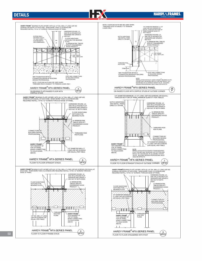
TM
TM
DETAILS
50
ON BEARING PLATE-RAISED FLOOR WITH
HARDY FRAME HFX-SERIES PANEL ® 5
HFX3 CRIPPLE STUDS
3" Minimum
WSP SHEAR WALL PER PLAN
SIM
POST AND CONNECTIONSBY BUILDING DESIGN PROFESSIONAL
EXTEND RIM A DISTANCE EQUAL TO THE FLOOR SYSTEM DEPTH (RECOMMENDED)
FLOOR SHEATHING NOTCHED FOR BEARING PLATE
NOTE: COUPLING NUTS MAY BE USED WHEN THREADED ROD IS SUBJECT TO TENSION LOADS ONLY.
4x MINIMUM RIM, TABLES SPECIFY ENGINEERED WOOD PRODUCT.
SEE FOUNDATION DETAILS.FOUNDATION DESIGN BY BUILDING DESIGN PROFESSIONAL
HARDY FRAME BEARING PLATE (HFXBP) WITH (6) 1/4" DIA. MIN x 3" LONG USP-WS SCREWS (OR EQUAL) AT EACH END. WHEN MORE THAN (12) SCREWS ARE REQUIRED INSTALL 1/4"x4-1/2" SCREWS THROUGH BASE OF PANEL.
®
HARDENED ROUND, (2) SAE OR (2) ROUND-FLAT WASHERS AND GRADE 8 HEX NUT.
HARDY FRAME HFX-SERIES PANEL ®
FLOOR TO FLOOR STRAIGHT STACK 6
HFX3
THREADED ROD PER PLANS
3"
1/4" DIAMETER MIN x 3" LONG USP-WS SCREWS (OR EQUAL) PER TABLE.
CONNECTORS BY BUILDING DESIGN PROFESSIONAL
FLOOR SHEATHING NOTCHED FOR BEARING PLATE
4x MINIMUM RIM, TABLES SPECIFY ENGINEERED WOOD PRODUCT.
HARDY FRAME BEARING PLATE (HFXBP) WITH (6) 1/4" DIA. MIN x 3" LONG USP-WS SCREWS (OR EQUAL) AT EACH END. WHEN MORE THAN (12) SCREWS ARE REQUIRED INSTALL 1/4"X4-1/2" SCREWS THROUGH BASE OF PANEL.
®
HARDENED ROUND, (2) SAE OR (2) ROUND-FLAT WASHERS AND GRADE 8 HEX NUT AT BOTH ENDS.
HARDY FRAME "STK WASHER" AT TOP OF PANEL WHEN CONNECTING TO HOLD DOWN ABOVE.
®
THREADED ROD PER PLANS
FLOOR TO FLOOR PYRAMID STACK
HARDY FRAME HFX-SERIES PANEL ®
FLOOR SHEATHING NOTCHED FOR BEARING PLATE
4x MINIMUM RIM, TABLES SPECIFY ENGINEERED WOOD PRODUCT.
8HFX3
1/4" DIA. MIN x 3" LONG USP-WS SCREWS (OR EQUAL) PER TABLE.
HARDENED ROUND, (2) SAE OR (2) ROUND-FLAT WASHERS AND GRADE 8 HEX NUT AT BOTH ENDS.
HARDY FRAME BEARING PLATE (HFXBP) WITH (6) 1/4" DIA. MIN x 3" LONG USP-WS SCREWS (OR EQUAL) AT EACH END. WHEN MORE THAN (12) SCREWS ARE REQUIRED INSTALL 1/4"X4-1/2" SCREWS THROUGH BASE OF PANEL.
®
HARDY FRAME "STK WASHER" AT TOP OF PANEL WHEN CONNECTING TO HOLD DOWN ABOVE.
®
FLOOR TO FLOOR STAGGERED WITH POST
THREADED ROD PER PLANS
HARDY FRAME HFX-SERIES PANEL ®
CONNECTORS BY BUILDING DESIGN PROFESSIONAL
FLOOR SHEATHING NOTCHED FOR BEARING PLATE
4x MINIMUM RIM, TABLES SPECIFY ENGINEERED WOOD PRODUCT.
9HFX3
1/4" DIAMETER MINIMUM x 3" LONG USP-WS SCREWS (OR EQUAL) PER TABLE.
HARDY FRAME BEARING PLATE (HFXBP) WITH (6) 1/4" DIA. MIN x 3" LONG USP-WS SCREWS (OR EQUAL) AT EACH END. WHEN MORE THAN (12) SCREWS ARE REQUIRED INSTALL 1/4"X4-1/2" SCREWS THROUGH BASE OF PANEL.
®
HARDENED ROUND, (2) SAE OR (2) ROUND-FLAT WASHERS AND GRADE 8 HEX NUT AT BOTH ENDS.
HARDY FRAME "STK WASHER" AT TOP OF PANEL WHEN CONNECTING TO HOLD DOWN ABOVE.
®
HARDY FRAME HFX-SERIES PANEL ®
FLOOR TO FLOOR STRAIGHT STACK AT OUTSIDE 7
HFX3CORNER
NOTCH SHEATHING AND INSTALL PANEL DIRECTLY ON RIM
THREADED ROD PER PLANS
CONNECTORS BY BUILDING DESIGN PROFESSIONAL
4x MINIMUM RIM, TABLES SPECIFY ENGINEERED WOOD PRODUCT.
NOTE:INSTALLATION WITHOUT HARDY FRAME BEARING PLATE (HFXBP) MAY INCREASE DEFLECTION AND RESULT IN A DECREASE OF ALLOWABLE SHEAR VALUE. BUILDING DESIGN PROFESSIONAL MUST ANALYZE EFFECTS
1/4" DIAMETER MINIMUM x 3" LONG USP-WS SCREWS (OR EQUAL) PER TABLE.
1/4" DIAMETER MINIMUM x 4 1/2" LONG USP-WS SCREWS (OR EQUAL) THROUGH BOTTOM OF PANEL MINIMUM QUANTITY PER TABLES
HARDENED ROUND, (2) SAE OR (2) ROUND-FLAT WASHERS AND GRADE 8 HEX NUT AT BOTH ENDS.
HARDY FRAME "STK WASHER" AT TOP OF PANEL WHEN CONNECTING TO HOLD DOWN ABOVE.
®
WSP SHEAR WALL PER PLAN
ON RAISED FLOOR WITH CRIPPLE STUDS AT OUTSIDE CORNER
THREADED RODPER PLANS
3"Minimum
NOTCH SHEATHING AND INSTALL PANEL DIRECTLY ON RIM
3E P
HARDY FRAME HFX-SERIES PANEL ®
POST AND CONNECTIONSBY BUILDING DESIGN PROFESSIONAL
NOTE: COUPLING NUTS MAY BE USED WHEN THREADED ROD IS SUBJECT TO TENSION LOADS ONLY.
4x MINIMUM RIM, TABLES SPECIFY ENGINEERED WOOD PRODUCT.
1/4" DIAMETER MINIMUM x 4 1/2" LONG USP-WS SCREWS (OR EQUAL) THROUGH BOTTOM OF PANEL MINIMUM QUANTITY PER TABLES
NOTE:INSTALLATION WITHOUT HARDY FRAME BEARING PLATE (HFXBP) MAY INCREASE DEFLECTION AND RESULT IN A DECREASE OF ALLOWABLE SHEAR VALUE. BUILDING DESIGN PROFESSIONAL MUST ANALYZE EFFECTS
®
SEE FOUNDATION DETAILS.FOUNDATION DESIGN BY BUILDING DESIGN PROFESSIONAL
HARDENED ROUND, (2) SAE OR (2) ROUND-FLAT WASHERS AND GRADE 8 HEX NUT.

TM
TM
DETAILS
5B P
HARDY FRAME HFX-SERIES PANEL ®
ON BEAM WITH HOLD DOWN STRAPS
BUILDING DESIGN PROFESSIONAL TO DESIGN1. LOAD PATH FROM BEAM TO FOUNDATION.2. INSTALLATION WITHOUT HARDY FRAME BEARING PLATE (HFXBP) INCREASES PANEL DEFLECTION AND MAY RESULT IN A DECREASE OF ALLOWABLE SHEAR VALUES. BUILDING DESIGN PROFESSIONAL MUST ANALYZE EFFECTS.3. BEAM DEFLECTION MAY INCREASE TOTAL DRIFT OF PANEL. BUILDING DESIGN PROFESSIONAL MUST ANALYZE EFFECTS.4. STRAP DESIGN, QUANITY AND CONNECTIONS (WELDED OR SELF TAPPING SCREWS)
WOOD BEAM PER PLAN
1/4" DIAMETER (MINIMUM) x 4 1/2" LONG USP-WS SCREWS (OR EQUAL) THROUGH BOTTOM OF PANEL PER TABLE.
NOTE:AREA AT BOTTOM CHANNEL HAS 2-LAYERS OF NO. 12 GAGE STEEL. AVOID USING SCREWED CONNECTIONS IN THIS AREA.
®
WHEN INSTALLING A HARDY FRAME BEARING PLATE (HFXBP) AT STRAP CONNECTION THE SHEAR TRANSFER THROUGH THE PANEL BASE MUST BE WITHIN THE FOLLOWING CAPACITIES:
(4) 1/4" DIA. SCREWS FOR 12" WIDE PANELS (6) 1/4" DIA. SCREWS FOR 18" WIDE PANELS (12) 1/4" DIA. SCREWS FOR 24" WIDE PANELS
®
ON STEEL BEAM WITH WELDED HOLD DOWNS
HARDY FRAME HFX-SERIES PANEL ®
13HFX3
STEEL BEAM BY BUILDING DESIGN PROFESSIONAL
1/4" DIAMETER (MINIMUM) USP-WS SCREWS (OR EQUAL) MAY BE INSTALLED FOR ADDITIONAL SHEAR TRANSFER
ON OPEN WEB TRUSSHARDY FRAME HFX-SERIES PANEL ®
14HFX3
1/4" DIAMETER (MINIMUM) USP-WS SCREWS (OR EQUAL) WITH FULL PENETRATION INTO TOP CHORD OF BLOCK.
END BLOCK CONFIGURATION MAY CHANGE TO ACCOMMODATE SPECIFIC JOB CONDITIONS.
TRUSS DESIGN AND CONNECTIONS BY TRUSS DESIGN PROFESSIONAL
NOTE:1. INSTALLATION WITHOUT HARDY FRAME BEARING PLATE (HFXBP) INCREASES DEFLECTION AND MAY RESULT IN A DECREASE OF ALLOWABLE SHEAR VALUES BUILDING DESIGN PROFESSIONAL MUST ANALYZE EFFECTS.
2. TRUSS DESIGN PROFESSION TO CHECK LATERAL SHEAR AND OVERTURNING MOMENT OF TRUSS SYSTEM.
®
POST
HARDY FRAME HFX-SERIES PANEL ®
CONNECTORS BY BUILDING DESIGN PROFESSIONAL
FLOOR SHEATHING NOTCHED FOR BEARING PLATE
4x MINIMUM RIM, TABLES SPECIFY ENGINEERED WOOD PRODUCT.
ON UPPER FLOOR TO POSTS BELOW10
HFX3
POST
HARDY FRAME BEARING PLATE (HFXBP) WITH (6) 1/4" DIA. MIN x 3" LONG USP-WS SCREWS (OR EQUAL) AT EACH END. WHEN MORE THAN (12) SCREWS ARE REQUIRED INSTALL 1/4"X4-1/2" SCREWS THROUGH BASE OF PANEL.
®
HARDENED ROUND, (2) SAE OR (2) ROUND-FLAT WASHERS AND GRADE 8 HEX NUT AT BOTH ENDS.
FLOOR TO FLOOR STAGGERED WITH PLATE WASHER
HARDY FRAME HFX-SERIES PANEL ®
CONNECTORS BY BUILDING DESIGN PROFESSIONAL
FLOOR SHEATHING NOTCHED FOR BEARING PLATE
4x MINIMUM RIM, TABLES SPECIFY ENGINEERED WOOD PRODUCT.
1/4" DIAMETER MINIMUM x 3" LONG USP-WS SCREWS (OR EQUAL) PER TABLE.
THREADED ROD HOLD DOWN WITH PLATE WASHER AS DETERMINED BT THE BUILDING DESIGN PROFESSIONAL AT UNDERSIDE OF BEAM PER PLANS
11HFX3
HARDY FRAME BEARING PLATE (HFXBP) WITH (6) 1/4" DIA. MIN x 3" LONG USP-WS SCREWS (OR EQUAL) AT EACH END. WHEN MORE THAN (12) SCREWS ARE REQUIRED INSTALL 1/4"X4-1/2" SCREWS THROUGH BASE OF PANEL.
®
HARDENED ROUND, (2) SAE OR (2) ROUND-FLAT WASHERS AND GRADE 8 HEX NUT AT BOTH ENDS.
HARDY FRAME "STK WASHER" AT TOP OF PANEL WHEN CONNECTING TO HOLD DOWN ABOVE.
®
THREADED ROD HD PER PLANS
PLATE WASHER OR HARDY FRAME BEARING PLATE AT UNDERSIDE OF BEAM AS DETERMINED BY THE BUILDING DESIGN PROFESSIONAL
WOOD BEAM PER PLAN
HARDY FRAME HFX-SERIES PANEL ®
BUILDING DESIGN PROFESSIONAL TO DESIGN1. LOAD PATH FROM BEAM TO FOUNDATION.2. INSTALLATION WITHOUT HARDY FRAME BEARING PLATE (HFXBP) INCREASES PANEL DEFLECTION AND MAY RESULT IN A DECREASE OF ALLOWABLE SHEAR VALUES. BUILDING DESIGN PROFESSIONAL MUST ANALYZE EFFECTS.3. BEAM DEFLECTION MAY INCREASE TOTAL DRIFT OF PANEL. BUILDING DESIGN PROFESSIONAL MUST ANALYZE EFFECTS.
®
FLOOR SHEATHING NOTCHED FOR BEARING PLATE
ON BEAM WITH PLATE WASHERS BELOW12
HFX3
HARDY FRAME BEARING PLATE (HFXBP) WITH (6) 1/4" DIA. MIN x 3" LONG USP-WS SCREWS (OR EQUAL) AT EACH END. WHEN MORE THAN (12) SCREWS ARE REQUIRED INSTALL 1/4"X4-1/2" SCREWS THROUGH BASE OF PANEL.
®
HARDENED ROUND, (2) SAE OR (2) ROUND-FLAT WASHERS AND GRADE 8 HEX NUT.
HOLD DOWN THREADED ROD WELDED TO STEEL BEAM (BY BUILDING DESIGN PROFESSIONAL)
HARDENED ROUND, (2) SAE OR (2) ROUND-FLAT WASHERS AND GRADE 8 HEX NUT.
51

TM
TM
DETAILS
52
TOP TO DOUBLE PLATES
HARDY FRAME HFX-SERIES PANEL ® 1
HFX2
1/4" DIAMETER (MINIMUM) x 3" LONG USP-WS SCREW (OR EQUAL) PER TABLES.
TOP TO DOUBLE PLATES WITH 2x FILLERHARDY FRAME HFX-SERIES PANEL ®
2HFX2
2x WOOD FILLER CONNECTION WITH 1/4" DIAMETER (MINIMUM) x 4 1/2" LONG USP-WS SCREWS OR EQUAL.
®HARDY FRAME PANELS
TOP TO DOUBLE PLATES WITH 2x FILLER - FACE TO FACE CONDITION
HARDY FRAME HFX-SERIES PANEL ® 9
HFX2
WOOD MEMBER MAY BE INSERTED VERTICALLY OR HORIZONALLY IN CAVITY FOR BACKING AS NEEDED.
CAVITY ORIENTED FOR CONNECTION ACCESS.
2x WOOD FILLER CONNECTION WITH 1/4" DIAMETER (MINIMUM) x 4 1/2" LONG USP-WS SCREWS OR EQUAL.
TOP TO SLOPING DOUBLE PLATE WITH HARDY FRAME HFX-SERIES PANEL ®
4HFX2
BEVEL FILLER
SOLID 4X WOOD BEVEL RIPPED TO FIT SLOPE AND CONNECTORS BY BUILDING DESIGN PROFESSIONAL
1/4" DIAMETER (MINIMUM) x 3" LONG USP-WS SCREW (OR EQUAL) PER TABLES.
ADJACENT FRAMING FOR RESISTING OUT OF PLANE LOADS BY BUILDING DESIGN PROFESSIONAL
BUILDING DESIGN PROFESSIONAL MUST DESIGN:1. STUDS OR STRAPS TO TRANSFER UPLIFT OF FILLER MATERIAL 2. ADDITIONAL DRIFT DUE TO THE ADDITIONAL FILLER HEIGHT3. STUDS/POST AT EACH END OF PANEL FOR OUT OF PLANE LOAD
TOP TO DOUBLE PLATES WITH FILLER HEIGHT
HARDY FRAME HFX-SERIES PANEL ®
GREATER THAN 1-1/2 INCHES
3HFX2
4x WOOD FILLER BY BUILDING DESIGN PROFESSIONAL
CONNECTORS BY BUILDING DESIGN PROFESSIONAL
ADJACENT FRAMING FOR RESISTING OUT OF PLANE LOADS BY BUILDING DESIGN PROFESSIONAL
1/4" DIAMETER (MINIMUM) x 3" LONG USP-WS SCREW (OR EQUAL) PER TABLES.
TOP TO HEADER WITH CRIPPLE STUDS ABOVEHARDY FRAME HFX-SERIES PANEL ®
5HFX2
NOTE:STRAPS CONNECTING PANEL TO HEADER ARE RECOMMENDED. WHEN APPLIED IN THE FIELD STRAP DESIGN AND CONNECTION TO BE DETERMINED BY BUILDING DESIGN PROFESSIONAL.
CONTINUOUS HEADER PER PLAN
1/4" DIAMETER (MINIMUM) x 3" LONG USP-WS SCREW (OR EQUAL) PER TABLES.
SHEAR TRANSFER DESIGN AND DETAILS BY THE BUILDING DESIGN PROFESSIONAL

TM
TM
DETAILS
TOP TO STEEL BEAM WITH WOOD NAILER BELOWHARDY FRAME HFX-SERIES PANEL ®
7HFX2
STEEL BEAMPER PLANS
1/4" DIAMETER (MINIMUM) USP-WS SCREWS (OR EQUAL) FOR SHEAR TRANSFER FROM WOOD NAILER TO HARDY FRAME PANEL
®
CONNECTION BY BUILDING DESIGN PROFESSIONAL
TRIMMER (OR KINGSTUD @ OS CORNER) BY BUILDING DESIGN PROFESSIONAL.
NOTES:1. TRIMMERS PROVIDE FULL BEARING FOR HEADER ABOVE, DESIGN AND CONNECTIONS BY OTHERS. 2. TRIMMER ATTACHMENT TO PANEL NOT REQUIRED.3. ATTACHMENTS MAY BE MADE AT SCREW HOLES PROVIDED OR WITH SELF TAPPING SCREWS (#12 AT EDGES, #10 AT FACE).
HARDY FRAME HFX-SERIES PANEL ®
6x HEADER ABOVE - SECTION VIEW 6
HFX2
6x HEADER
TRIMMERBEYOND
®HARDY FRAME
PANEL
WOOD MEMBER MAY BE INSERTED VERTICALLY OR HORIZONALLY IN CAVITY FOR BACKING AS NEEDED.
BACKING (OPTIONAL)SET FLUSH TO FACE OF WALL
NOTE: ADDITIONAL LOADS APPLIED ON PANEL ARE TO BE EVENLY DISTRIBUTED AND MAY NOT EXCEED THE ALLOWABLE "P" LOAD AS PROVIDED IN TABLE 1.1.
®
PRE-DRILL 3/16" DIA. HOLE IN FACE OFHARDY FRAME PANELAND INSTALL EVENLYSPACED 1/4" DIA. USP-WS SCREWS THROUGH FACE,INTO 2x (MIN.) WOOD LEDGER LOCATEDIN PANEL CAVITY
CONNECTOR AND ATTACHMENT BY BUILDING DESIGN PROFESSIONAL
FOR 24" WIDE PANELSLEDGER TERMINATESINSIDE EDGE OF "POSTS"
VIEW OF PANEL CAVITY
HARDY FRAME HFX-SERIES PANEL ®11
HFX2CONCEALED LEDGER
4" MIN.
4"MIN.
1" MIN.
1" MIN.
4"MIN.
1
2
NOTES:1. THE SOLID FACE OF THE PANEL MAY BE ORIENTED TOWARDS THE INSIDE OR OUTSIDE FACE OF WALL. CHANGING THE ORIENTATION OF THE SOLID FACE WILL USUALLY PREVENT THE NEED FOR ADDITIONAL HOLES.2. TO DRILL HOLES LARGER THAN 1" DIAMETER, MORE THAN ONE HOLE OR HOLES LOCATED OUTSIDE THE DESIGNATED AREA, CONTACT HARDY FRAMES, INC.
A 3" DIAMETER HOLE IS PROVIDED IN THE FACE OF ALL 18" AND 24" WIDE PANELS
2
1
DESIGNATES AREA THAT ALLOWS ONE ADDITIONAL HOLE, UP TO 1" DIAMETER, TO BE DRILLED.
2
FOR THE 12" WIDE PANEL ONLY, THE DESIGNATED AREA FOR AN ADDITIONAL HOLE EXTENDS UN-INTERRUPTED FROM MID-HEIGHT TO 4" FROM THE TOP OF PANEL
UP
PE
R H
ALF
ADDITIONAL HOLE LOCATION CHARTHARDY FRAME HFX-SERIES PANEL ®
MID-HEIGHT
10HFX2
1 1/8" OUTSIDEDIAMETER
7/8" INSIDE DIAMETER
STRUCTURAL TUBE
3/4" THICK STEEL PLATEBUILT INTO BOTTOM OFPANEL BY MANUFACTURER
HARDY FRAME REDUCER(HFR)
INSTALLED AT 7/8" DIAMETER HOLD DOWN BOLT.
®
HARDY FRAME REDUCER (HFR)HFR
®
(HFR) EXPANDED VIEW
BOTTOM CHANNEL BELOW 3/4" STEEL PLATE
FOUNDATION DESIGN BY BUILDING DESIGN PROFESSIONAL
2x WOOD FILLER CONNECTION WITH 1/4" DIAMETER x 4 1/2" LONG USP-WS SCREWS (OR EQUAL). FOR FILLERS GREATER THAN 1 1/2" SEE DETAIL 3-HFX2.
A.B. PER PLANSMOISTURE BARRIER RECOMMENDED(USE 15# FELT, OR EQUIVALENT)
SIDE MEMBERS TO BE DESIGNED BY BUILDING DESIGN PROFESSIONAL FOR OUT-OF-PLANE AND VERTICAL LOADS. MINIMUM SIDE MEMBERS TO BE 4X6 OR 2-2x6 CONNECTED TOGETHER WITH 10d NAILS AT 16" OC
SIDE MEMBERS MAY BE ATTACHED TO PANEL WITH USP-WS SCREWS (OR
1/4" DIAMETER
THROUGH THE PANEL EDGE EQUAL)
INTO THE WOOD MEMBER. WHEN REQUIRED BY THE BUILDING DESIGN PROFESSIONAL ADDITIONAL ATTACHMENT MAY BE MADE WITH # 12 SELF TAPPING SCREWS.
BALLOON WALL INSTALLATION
3" Min.
14HFX2
®
USE HIGH STRENGTH THREADED ROD WITH 1/2"x3"x3" ASTM A 36 PLATE WASHERS DOUBLE NUTTED ON THE EMBED END. Hardy Frame BOLT BRACE (HFXBB) IS RECOMMENDED.
WELDED CONNECTIONBY HARDY FRAMES, INC.(NO FIELD CONNECTION REQUIRED)
HARDY FRAME HFX-SERIES PANEL ®
HARDENED ROUND, (2) SAE OR (2) ROUND-FLAT WASHERS AND GRADE 8 NUT.
53

TM
TM
DETAILS
54
BRACE FRAME
GARAGE FRONT PORTAL
OPTIONALSOFFIT
PER PLAN
PER PLAN
PER PLAN
KING STUDRECOMMEN-DED TRIMMER
RECOMMENDED
FURR TOP AS NECESSARY
PER PLAN
PER PLAN
GARAGE FRONT FULL HEIGHTBRACE FRAME
PER PLAN
TRIMMER PER PLAN
®
3" Minimum
HARDY FRAME HFX-SERIES BRACE FRAMEON FOUNDATION
FOUNDATION DESIGN BY BUILDING DESIGN PROFESSIONAL
1HFX4
MOISTURE BARRIER RECOMMENDED (USE 15# FELT, OR EQUIVALENT)
3"Minimum
®HARDY FRAME HFX-SERIES BRACE FRAMEON FOUNDATION AT RAISED FLOOR HEAD-OUT
FOUNDATION DESIGN BY BUILDING DESIGN PROFESSIONAL
ADJACENT FRAMING FOR RESISTING OUT OF PLANE LOADS BY BUILDING DESIGN PROFESSIONAL
1HFX6
7/8" DIAMETER HOLD DOWN BOLT WITH 1/2" THICK x 3"x 3" PLATE WASHER & 2-NUTS AT EMBED END PER PLAN.
7/8" DIAMETER HOLD DOWN BOLT WITH 1/2" THICK x 3"x 3" PLATE WASHER & 2-NUTS AT EMBED END PER PLAN.
HARDENED ROUND, (2) SAE OR (2) ROUND-FLAT WASHERS AND GRADE 8 HEX NUT.
HARDENED ROUND, (2) SAE OR (2) ROUND-FLAT WASHERS AND GRADE 8 HEX NUT.
MOISTURE BARRIER RECOMMENDED (USE 15# FELT, OR EQUIVALENT)
3"MinimumSEE FOUNDATION DETAIL 7-HFX4
FOR CONNECTION TO HEADER (PORTAL) DETAIL 5-HFX5 TO HEADERWHEN A 2x FILLER OCCURS SEE 6-HFX5
FOR TOP PLATE CONNECTION SEEDETAIL 1-HFX5 TOP PLATEDETAIL 2-HFX5 WITH 2x FILLERDETAIL 3-HFX5 FILLERS > 1 1/2"
FOR FACE TO FACE
BASE CONNECTION SEEDETAIL 4-HFX4 ON CONCRETE
OPTIONAL SOFFIT
TABLE 1.1A VALUESDETAIL 1-HFX4 ON CONCRETE
DETAIL 2-HFX4 ON NUT & WASHER
TABLE 1.2 VALUESDETAIL 3-HFX4 ON WOOD SILL
TABLE 1.2A VALUESSEE SHEET HFX6TABLE 1.3A VALUESSEE SHEET HFX6
FOR FACE TO FACE
TOP CONNECTION SEEDETAIL 11-HFX5DETAIL 12-HFX5 WITH 2x FILLER.
Detail Specification Guide
SPECIFY ANCHORAGE ON FOUNDATION PLAN PER ANCHORAGE NOMENCLATURE

TM
TM
DETAILS
3"Minimum
®HARDY FRAME HFX-SERIES BRACE FRAMEON NUT & WASHER (DOUBLE NUT)
FOUNDATION DESIGN BY BUILDING DESIGN PROFESSIONAL
7/8" DIAMETER HOLD DOWN BOLT WITH 1/2" THICK x 3"x 3" PLATE WASHER & 2-NUTS AT EMBED END PER PLAN.
PLUS OR MINUS 1-1/2" GAP TO BE FILLED WITH MINIMUM 5,000 PSI STRENGTH NON-SHRINK GROUT
2HFX4
3"Minimum
®HARDY FRAME HFX-SERIES BRACE FRAMEON WOOD SILL
FOUNDATION DESIGN BY BUILDING DESIGN PROFESSIONAL
7/8" DIAMETER HOLD DOWN BOLT WITH 1/2" THICK x 3"x 3" PLATE WASHER & 2-NUTS AT EMBED END PER PLAN.
3HFX4
HARDENED ROUND, (2) SAE OR (2) ROUND-FLAT WASHERS AND GRADE 8 HEX NUTS ABOVE AND BELOW BASE.
HARDENED ROUND, (2) SAE OR (2) ROUND-FLAT WASHERS AND GRADE 8 HEX NUT.
®HARDY FRAME HFX-SERIES BRACE FRAMEON RAISED FLOOR
3HFX6
3" Minimum
1/4" DIAMETER (MINIMUM) x 4 1/2" LONG USP-WS SCREWS (OR EQUAL) PER TABLES.
FOUNDATION DESIGN BY BUILDING DESIGN PROFESSIONAL
7/8" DIAMETER HOLD DOWN BOLT WITH 1/2" THICK x 3"x 3" PLATE WASHER & 2-NUTS AT EMBED END PER PLAN.
CONNECTORS BY BUILDING DESIGN PROFESSIONAL
NOTE:COUPLING NUTS MAY BE USED WHEN THREADED ROD IS SUBJECT TO TENSION LOADS ONLY.
4x MINIMUM RIM, TABLES SPECIFY ENGINEERED WOOD PRODUCT.
HARDENED ROUND, (2) SAE OR (2) ROUND-FLAT WASHERS AND GRADE 8 HEX NUT.
WSP SHEAR WALL PER PLAN
®HARDY FRAME HFX-SERIES BRACE FRAMEON RAISED FLOOR WITH CRIPPLE STUDS
FOUNDATION DESIGN BY BUILDING DESIGN PROFESSIONAL
7/8" DIAMETER HOLD DOWN BOLT WITH 1/2" THICK x 3"x 3" PLATE WASHER & 2-NUTS AT EMBED END PER PLAN.
3"Minimum
4x MINIMUM RIM, TABLES SPECIFY ENGINEERED WOOD PRODUCT.
NOTE:COUPLING NUTS MAY BE USED WHEN THREADED ROD IS SUBJECT TO TENSION LOADS ONLY.
POST AND CONNECTIONSBY BUILDING DESIGN PROFESSIONAL
EXTEND RIM A DISTANCE EQUAL TO THE FLOOR SYSTEM DEPTH (RECOMMENDED)
5HFX6
1/4" DIAMETER (MINIMUM) x 4 1/2" LONG USP-WS SCREWS (OR EQUAL) PER TABLES.
HARDENED ROUND, (2) SAE OR (2) ROUND-FLAT WASHERS AND GRADE 8 HEX NUT.
®HARDY FRAME HFX-SERIES BRACE FRAMEFLOOR TO FLOOR STRAIGHT STACK
CONNECTORS BY BUILDING DESIGN PROFESSIONAL
4x MINIMUM RIM, TABLES SPECIFY ENGINEERED WOOD PRODUCT.
6HFX6
1/4" DIAMETER (MINIMUM) x 3" LONG USP-WS SCREWS (OR EQUAL) PER TABLE.
1/4" DIAMETER (MINIMUM) x 4 1/2" LONG USP-WS SCREWS (OR EQUAL) PER TABLES.
7/8" DIA. THREADED ROD WITH HARDENED ROUND, (2) SAE OR (2) ROUND-FLAT WASHERS AND GRADE 8 HEX NUT AT BOTH ENDS.
FOUNDATION DESIGN BY BUILDING DESIGN PROFESSIONAL
2x BOTTOM PLATEBELOW BRACE FRAME
ON RAISED FLOOR - FLUSH JOIST CONDITION
2
®HARDY FRAME BRACE FRAME
®HARDY FRAME HFX-SERIES BRACE FRAME
HFX6
HARDENED ROUND, (2) SAE OR (2) ROUND-FLAT WASHERS AND GRADE 8 HEX NUT.
55

TM
TM
DETAILS
56
®HARDY FRAME HFX-SERIES BRACE FRAMEON BEAM WITH PLATE WASHERS BELOW
12HFX6
SOLID BEAMPER PLANS
1/4" DIAMETER (MINIMUM) x 4 1/2" LONG USP-WS SCREWS (OR EQUAL) PER TABLES.
THREADED ROD HOLD DOWN WITH PLATE WASHER AS DETERMINED BT THE BUILDING DESIGN PROFESSIONAL AT UNDERSIDE OF BEAM PER PLANS
BUILDING DESIGN PROFESSIONAL TO DESIGN1. LOAD PATH FROM BEAM TO FOUNDATION.2. BEAM DEFLECTION MAY INCREASE TOTAL DRIFT OF BRACE FRAME. BUILDING DESIGN PROFESSIONAL MUST ANALYZE EFFECTS.
5BBF
®HARDY FRAME HFX-SERIES BRACE FRAMEON BEAM WITH HOLD DOWN STRAPS
WOOD BEAM PER PLANS
1/4" DIAMETER (MINIMUM) x 4 1/2" LONG USP-WS SCREWS (OR EQUAL) PER TABLES.
BUILDING DESIGN PROFESSIONAL TO DESIGN1. LOAD PATH FROM BEAM TO FOUNDATION.2. BEAM DEFLECTION MAY INCREASE TOTAL DRIFT OF BRACE FRAME. BUILDING DESIGN PROFESSIONAL MUST ANALYZE EFFECTS.3. STRAP DESIGN, QUANITY AND CONNECTIONS (WELDED OR SELF TAPING SCREWS)
NOTE:AREA AT BOTTOM CHANNEL HAS 2-LAYERS OF NO. 12 GAGE STEEL. AVOID USING SCREWED CONNECTIONS IN THIS AREA.
®
POSTHARDY FRAME
®HARDY FRAME HFX-SERIES BRACE FRAMEFLOOR TO FLOOR STAGGERED WITH POST
CONNECTORS BY BUILDING DESIGN PROFESSIONAL
4x MINIMUM RIM, TABLES SPECIFY ENGINEERED WOOD PRODUCT.
9HFX6
1/4" DIAMETER (MINIMUM) x 3" LONG USP-WS SCREWS (OR EQUAL) PER TABLE.
1/4" DIAMETER (MINIMUM) x 4 1/2" LONG USP-WS SCREWS (OR EQUAL) PER TABLES.
7/8" DIA. THREADED ROD WITH HARDENED ROUND, (2) SAE OR (2) ROUND-FLAT WASHERS AND GRADE 8 HEX NUT AT BOTH ENDS.
®POSTHARDY FRAME
®HARDY FRAME HFX-SERIES BRACE FRAMEON UPPER FLOOR TO POSTS BELOW
CONNECTORS BY BUILDING DESIGN PROFESSIONAL
4x MINIMUM RIM, TABLES SPECIFY ENGINEERED WOOD PRODUCT.
10HFX6
1/4" DIAMETER (MINIMUM) x 4 1/2" LONG USP-WS SCREWS (OR EQUAL) PER TABLES.
7/8" DIA. THREADED ROD WITH HARDENED ROUND, (2) SAE OR (2) ROUND-FLAT WASHERS AND GRADE 8 HEX NUT AT BOTH ENDS.
®HARDY FRAME HFX-SERIES BRACE FRAMEFLOOR TO FLOOR STAGGERED WITH PLATE WASHER
CONNECTORS BY BUILDING DESIGN PROFESSIONAL
4x MINIMUM RIM, TABLES SPECIFY ENGINEERED WOOD PRODUCT.
11HFX6
1/4" DIAMETER (MINIMUM) x 3" LONG USP-WS SCREWS (OR EQUAL) PER TABLE.
1/4" DIAMETER (MINIMUM) x 4 1/2" LONG USP-WS SCREWS (OR EQUAL) PER TABLES.
7/8" DIA. THREADED ROD WITH HARDENED ROUND, (2) SAE OR (2) ROUND-FLAT WASHERS AND GRADE 8 HEX NUT AT BOTH ENDS.
THREADED ROD HOLD DOWN WITH PLATE WASHER AS DETERMINED BT THE BUILDING DESIGN PROFESSIONAL AT UNDERSIDE OF BEAM PER PLANS
3/4" THICK STEEL PLATE WASHER BUILT INTO BOTTOM OF BRACE FRAME (BY MANUFACTURER)
®
HARDY FRAME HFX-SERIES BRACE FRAMEFLOOR TO FLOOR PYRAMID STACK
CONNECTORS BY BUILDING DESIGN PROFESSIONAL
4x MINIMUM RIM, TABLES SPECIFY ENGINEERED WOOD PRODUCT.
7/8" DIA. THREADED ROD WITH HARDENED ROUND, (2) SAE OR (2) ROUND-FLAT WASHERS AND GRADE 8 HEX NUT AT BOTH ENDS.
8HFX6
1/4" DIAMETER (MINIMUM) x 4 1/2" LONG USP-WS SCREWS (OR EQUAL) PER TABLES.
1/4" DIAMETER (MINIMUM) x 3" LONG USP-WS SCREWS (OR EQUAL) PER TABLE.
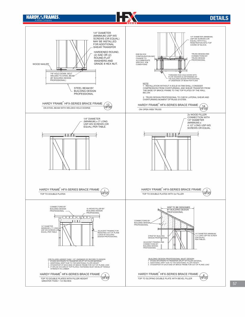
TM
TM
DETAILS
®
HARDY FRAME HFX-SERIES BRACE FRAMEON STEEL BEAM WITH WELDED HOLD DOWNS
13HFX6
WOOD NAILER
STEEL BEAM BY BUILDING DESIGN PROFESSIONAL
1/4" DIAMETER (MINIMUM) USP-WS SCREWS (OR EQUAL) MAY BE INSTALLED FOR ADDITIONAL SHEAR TRANSFER
®HARDY FRAME HFX-SERIES BRACE FRAMETOP TO DOUBLE PLATES
1HFX5
1/4" DIAMETER (MINIMUM) x 3" LONG USP-WS SCREWS (OR EQUAL) PER TABLE.
®HARDY FRAME HFX-SERIES BRACE FRAMETOP TO DOUBLE PLATES WITH 2x FILLER
2HFX5
2x WOOD FILLER CONNECTION WITH 1/4" DIAMETER (MINIMUM) x 4 1/2" LONG USP-WS SCREWS OR EQUAL.
®HARDY FRAME HFX-SERIES BRACE FRAMETOP TO DOUBLE PLATES WITH FILLER HEIGHTGREATER THAN 1 1/2 INCHES
3HFX5
FOR FILLERS LARGER THAN 1 1/2", ENGINEER OF RECORD TO DESIGN:1. STUDS OR STRAPS TO TRANSFER UPLIFT OF FILLER MATERIAL 2. ADDITIONAL DRIFT DUE TO THE ADDITIONAL FILLER HEIGHT3. STUDS/POST AT EACH END OF BRACE FRAME FOR OUT OF PLANE LOAD4. IF SPLICE OCCURS AT TOP PLATES, FASTENING MUST DEVELOP TENSILE STRENGTH IN LUMBER
CONNECTORS BY BUILDING DESIGN PROFESSIONAL
1/4" DIAMETER (MINIMUM) x 3" LONG USP-WS SCREWS (OR EQUAL) PER TABLE.
ADJACENT FRAMING FOR RESISTING OUT OF PLANE LOADS BY BUILDING DESIGN PROFESSIONAL
4x WOOD FILLER BY BUILDING DESIGN PROFESIONAL
®
HARDY FRAME HFX-SERIES BRACE FRAMETOP TO SLOPING DOUBLE PLATE WITH BEVEL FILLER
4HFX5
ADJACENT FRAMING AND CONNECTIONS BY BUILDING DESIGN PROFESSIONAL
STRAP BY BUILDING DESIGN PROFESSIONAL
WSP TO BE DESIGNED BY BUILDING DESIGN PROFESSIONAL
1/4" DIAMETER (MINIMUM) x 3" LONG USP-WS SCREW (OR EQUAL) PER TABLES.
BUILDING DESIGN PROFESSIONAL MUST DESIGN:1. STUDS OR STRAPS TO TRANSFER UPLIFT OF FILLER MATERIAL 2. ADDITIONAL DRIFT DUE TO THE ADDITIONAL FILLER HEIGHT3. STUDS/POST AT EACH END OF BRACE FRAME FOR OUT OF PLANE LOAD
CONNECTORS BY BUILDING DESIGN PROFESSIONAL
7/8" HOLD DOWN BOLT WELDED TO STEEL BEAM (BY BUILDING DESIGN PROFESSIONAL)
HARDENED ROUND, (2) SAE OR (2) ROUND-FLAT WASHERS AND GRADE 8 HEX NUT.
NOTE:1. INSTALLATION WITHOUT A SOLID 4X RIM SHALL CONSIDER COMPRESSION FROM OVERTURNING, AND SHEAR TRANSFER FROM THE BASE OF BRACE FRAME TO THE TOP PLATES OF THE WALL BELOW.
2. TRUSS DESIGN PROFESSIONAL TO CHECK LATERAL SHEAR AND OVERTURNING MOMENT OFTRUSS SYSTEM.
®HARDY FRAME HFX-SERIES BRACE FRAMEON OPEN WEB TRUSS
END BLOCK CONFIGURATION MAY CHANGE TO ACCOMMODATE SPECIFIC JOB CONDITIONS.
TRUSS DESIGN AND CONNECTIONS BY TRUSS DESIGN PROFESSIONAL
14HFX6
1/4" DIAMETER (MINIMUM) USP-WS SCREWS (OR EQUAL) WITH FULL PENETRATION INTO TOP CHORD OF BLOCK.
THREADED ROD HOLD DOWN WITH PLATE WASHER AS DETERMINED BT THE BUILDING DESIGN PROFESSIONAL AT UNDERSIDE OF BEAM PER PLANS
57
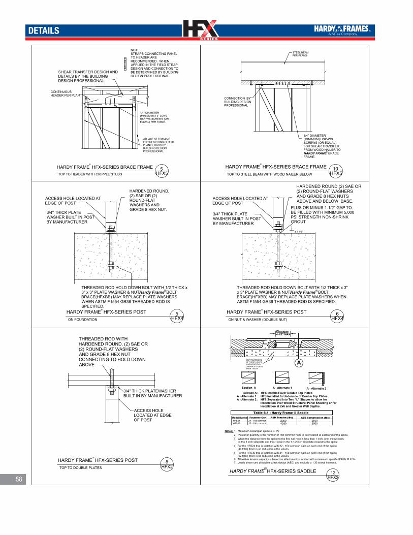
TM
TM
DETAILS
58
®
HARDY FRAME HFX-SERIES BRACE FRAMETOP TO HEADER WITH CRIPPLE STUDS
5HFX5
1/4" DIAMETER (MINIMUM) x 3" LONG USP-WS SCREWS (OR EQUAL) PER TABLE.
NOTE:STRAPS CONNECTING PANEL TO HEADER ARE RECOMMENDED. WHEN APPLIED IN THE FIELD STRAP DESIGN AND CONNECTION TO BE DETERMINED BY BUILDING DESIGN PROFESSIONAL.
CONTINUOUS HEADER PER PLAN
ADJACENT FRAMING FOR RESISTING OUT OF PLANE LOADS BY BUILDING DESIGN PROFESSIONAL
STEEL BEAM PER PLANS
®HARDY FRAME HFX-SERIES BRACE FRAMETOP TO STEEL BEAM WITH WOOD NAILER BELOW
CONNECTION BY BUILDING DESIGN PROFESSIONAL
10HFX5
1/4" DIAMETER (MINIMUM) USP-WS SCREWS (OR EQUAL) FOR SHEAR TRANSFER FROM WOOD NAILER TO HARDY FRAME BRACE FRAME.
®
ACCESS HOLE LOCATED AT EDGE OF POST
THREADED ROD HOLD DOWN BOLT WITH 1/2 THICK x 3" x 3" PLATE WASHER & NUT. Hardy Frame BOLT BRACE(HFXBB) MAY REPLACE PLATE WASHERS WHEN ASTM F1554 GR36 THREADED ROD IS SPECIFIED.
®
®HARDY FRAME HFX-SERIES POSTON FOUNDATION
3/4" THICK PLATE WASHER BUILT IN POST BY MANUFACTURER
5HFX4
± 1 1/2"
3/4" THICK PLATE WASHER BUILT IN POST BY MANUFACTURER
ACCESS HOLE LOCATED AT EDGE OF POST
®
®HARDY FRAME HFX-SERIES POSTON NUT & WASHER (DOUBLE NUT)
THREADED ROD HOLD DOWN BOLT WITH 1/2 THICK x 3" x 3" PLATE WASHER & NUT. Hardy Frame BOLT BRACE(HFXBB) MAY REPLACE PLATE WASHERS WHEN ASTM F1554 GR36 THREADED ROD IS SPECIFIED.
PLUS OR MINUS 1-1/2" GAP TO BE FILLED WITH MINIMUM 5,000 PSI STRENGTH NON-SHRINK GROUT
6HFX4
ACCESS HOLE LOCATED AT EDGE OF POST
3/4" THICK PLATEWASHER BUILT IN BY MANUFACTURER
®HARDY FRAME HFX-SERIES POSTTOP TO DOUBLE PLATES
8HFX2
HARDY FRAME HFX-SERIES SADDLE ®
12HFX2
Section A A - Alternate 1 Section A : HFS Installed over Double Top PlatesA - Alternate 1 : HFS Installed to Underside of Double Top PlatesA - Alternate 2 : HFS Separated into Two "L" Shapes to allow for Installation over Wood Structural Panel Sheeting or for Installation at 2x6 and Greater Wall Depths.
Table 8.1 : Hardy Frame ® SaddleModel Number
Fastener Qty ASD Tension (lbs) ASD Compression (lbs)24 - 16d common32 - 16d common
29504280 2500
2500HFS24HFS36
Notes: 1) Maximum Clearspan splice is 4-1/2"
2) Fastener quantity is the number of 16d common nails to be installed at each end of the splice. 3) When the distance from the splice to the first nail hole is less than 1 inch, omit the (2) nails in the 3 inch sideplate and the (1) nail in the 1-1/2 inch sideplate closest to the splice. 4) For the HFS24 that is installed with 22 - 16d common nails on each end of the splice (44 total) there is no reduction in the values. 5) For the HFS36 that is installed with 31 - 16d common nails on each end of the splice (62 total) there is no reduction in the values.
Clearspan4-1/2" MAX
OMIT FASTENERSAT THESE HOLESWHEN THE END DISTANCE IS LESSTHAN 1 INCH.
6) Allowable tension capacity is based on attachment to lumber with a minimum specific gravity of 0.49.7) Loads shown are allowable stress design (ASD) and exclude a 1.33 stress increase.
A - Alternate 2
A
SHEAR TRANSFER DESIGN AND DETAILS BY THE BUILDING DESIGN PROFESSIONAL
HARDENED ROUND, (2) SAE OR (2) ROUND-FLAT WASHERS AND GRADE 8 HEX NUT.
HARDENED ROUND,(2) SAE OR (2) ROUND-FLAT WASHERS AND GRADE 8 HEX NUTS ABOVE AND BELOW BASE.
THREADED ROD WITH HARDENED ROUND, (2) SAE OR (2) ROUND-FLAT WASHERS AND GRADE 8 HEX NUT CONNECTING TO HOLD DOWN ABOVE
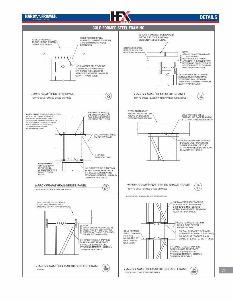
TM
TM
DETAILS
1ASBF
STEEL FRAMING AT FLOOR / ROOF SYSTEM ABOVE BY BUILDING DESIGN PROFESSIONAL
1/4" DIAMETER SELF TAPPING SCREWS MUST PENETRATE3-THREADS (MIN.) BEYOND ATTACHING MEMBER. MINIMUM QUANTITY PER TABLE.
HARDY FRAME HFX/S-SERIES BRACE FRAME ®
TOP TO COLD FORMED STEEL CHANNEL
COLD FORMED STEEL CHANNEL (18 GAGE MINIMUM)3 1/2" (MIN.) INSIDE DIMENSION
1BSBF
HARDY FRAME HFX/S-SERIES BRACE FRAME®
PORTAL
1/4" DIAMETER SELF TAPPING SCREWS MUST PENETRATE3-THREADS (MIN.) BEYOND ATTACHING MEMBER. MINIMUM QUANTITY PER TABLE.
CONTINUOUS COLD FORMED STEEL HEADER DESIGN BY BUILDING DESIGN PROFESSIONAL
NOTE:WHEN STRAPS ARE APPLIED IN FIELD, #10 x 3/4" SELF TAPPING SCREWS WITH A SELF DRILLING TIP ARE RECOMMENDED.
COLD FORMED STEEL RIM BY BUILDING DESIGN PROFESSIONAL
DIAGONAL MAY BE ORIENTED IN EITHER DIRECTION.
2ASBF
1/4" DIAMETER SELF TAPPING SCREWS MUST PENETRATE3-THREADS (MIN.) BEYOND ATTACHING MEMBER. MINIMUM QUANTITY PER TABLE.
1/4" DIAMETER SELF TAPPING SCREWS MUST PENETRATE3-THREADS (MIN.) BEYOND ATTACHING MEMBER. MINIMUM QUANTITY PER TABLE.
HARDY FRAME HFX/S-SERIES BRACE FRAME®
FLOOR TO FLOOR STRAIGHT STACK
COLD FORMED STEEL CHANNEL (18 GAGE MINIMUM) 3 1/2" (MIN.) INSIDE DIMENSION
TOP TO STEEL HEADER WITH CRIPPLE STUDS ABOVE
CONTINUOUS STEEL HEADER BY BUILDING DESIGN PROFESSIONAL
1/4" DIAMETER SELF TAPPING SCREWS MUST PENETRATE3-THREADS (MIN.) BEYOND ATTACHING MEMBER. MINIMUM QUANTITY PER TABLE.
1BSP
HARDY FRAME HFX/S-SERIES PANEL ®
NOTE:STRAPS CONNECTING PANEL TO HEADER ARE RECOMMENDED. WHEN APPLIED IN THE FIELD STRAP DESIGN AND CONNECTION TO BE DETERMINED BY BUILDING DESIGN PROFESSIONAL.
HARDY FRAME HFX/S-SERIES PANEL
STEEL FRAMING AT FLOOR / ROOF SYSTEM ABOVE PER PLANS
®
1ASPTOP TO COLD FORMED STEEL CHANNEL
1/4" DIAMETER SELF TAPPING SCREWS MUST PENETRATE 3-THREADS (MIN.) BEYOND ATTACHING MEMBER. MINIMUM QUANTITY PER TABLE.
COLD FORMED STEEL CHANNEL (18 GAGE MINIMUM)3 1/2" (MININIMUM) INSIDE DIMENSION
SHEAR TRANSFER DESIGN AND DETAILS BY THE BUILDING DESIGN PROFESSIONAL
HARDENED ROUND, (2) SAE OR (2) ROUND-FLAT WASHERS AND GRADE 8 HEX NUT AT BOTH ENDS.
HARDY FRAME"STK WASHER" AT TOP OF PANEL WHEN CONNECTING TO HOLD DOWN ABOVE.
®
1 1/8" DIA. THREADED ROD
COLD FORMED STEEL RIM BELOW PANEL
2ASP
1/4" DIAMETER SELF TAPPING SCREWS MUST PENETRATE3-THREADS (MIN.) BEYOND ATTACHING MEMBER. MINIMUM QUANTITY PER TABLE.
HARDY FRAME HFX/S-SERIES PANEL®
FLOOR TO FLOOR STRAIGHT STACK
7/8" DIA. THREADED ROD WITH HARDENED ROUND, (2) SAE OR (2) ROUND-FLAT WASHERS AND GRADE 8 HEX NUT AT BOTH ENDS.
HARDY FRAME® BEARING PLATE (HFXBP) WITH (6) 1/4" DIA MIN SCREWS AT EACH END. WHEN MORE THAN 12 SCREWS ARE REQUIRED INSTALL 1/4" SCREWS THROUGH BASE OF PANEL. ALL SCREWS MUST PENETRATE 3-THREADS (MIN) BEYONDATTACHING MEMBER.
COLD FORMED STEEL FRAMING
59

TM
TM
60
ANCHORAGE
Ie = Length of EmbedCa1 Ca2 = Edge, End Distance
GROUTFILLED CMUOR CONCRETE(PER PLAN)
FOOTING DEPTH AND
WIDTH MAY DECREASE
BEYOND Ca1 DIMENSION
VARIES WITHPANEL/BRACEFRAME WIDTH
BOLT BRACESEE TABLENOTE 7
Ca1
Ca1 Ca1
Ca1 Ca1
Ca2 Ca2
L t
Ca1
4˝ MIN
3˝
# 3 REBAR TIE SEETABLE FOR REQUIREDQUANTITY
NOTE: COUPLING NUTS MAY BE USED TOEXTEND ALL THREAD ROD LENGTH THROUGH
GROUT FILLED CMU
# 3 REBAR, GRADE 60 (MIN) TIE
FIELD TIE TABLE FOR OVERLAP
H.D.
HOLD DOWN ANCHOR
3˝MIN.
3˝MIN.
3˝MIN.
3˝MIN.
STEM WALL ELEVATION
SHEAR TIE @ CURB SHEAR TIE REINFORCEMENTCURB ELEVATION
EXTERIOR SLAB ELEVATION
INTERIOR SLAB ELEVATION
ANCHORAGE - PLAN VIEW
PER
PLAN
10 IN
CHM
AXIM
UM O
RPE
R PL
ANS
10 IN
CHM
AXIM
UM O
RPE
R PL
ANS
Ie
Ie
Ie
Ie
Ca 1 Ca 2le
ROD GRADEROD DIAMETER
ANCHORAGE NOMENCLATURE1 1/8-STD-14-20
C a2
C a2
C a1 C a1
1) Applies to 2500 psi compressive strength concrete, both seismic and wind loading2) STD indicates rods complying with ASTM F1554 Grade 36 with a Hardy Frame® Bolt Brace (HFXBB) double nutted on the embed end.3) HS indicates rods complying with ASTM A 193 Grade B7 (or equal) with a1/2x3x3 plate washer double nutted on the embed end. HFXBB is optional.4) Concrete edge distance must comply with ACI318-05 D8.2.5) Installations on curbs or stemwalls must be 6 inch width minimum, and may require supplemental shear reinforcement per ACI-318-05, fc = 2500 psi6) Shear Ties are not required for installations away from the Foundation Edge, for installations on wood framing or for Braced Wall Panel applications.7) Bolt Brace is used for bolt alignment. When used with STD grade rods plate washers are not required. When used with HS grade rods plate washers are still required.8) Foundation Design is by others9) The Building Design Professional is permitted to modify these details to accommodate a speci�c condition.
ProductWidth(in)
MaxHeight
(ft)
Anchorage1
(See Nomenclature for Description)Shear Tie4, 5, 6
Quantity Tie Length(in)STD ROD2 HS ROD3 STD ROD HS ROD
9 8 1 1/8-STD-10-15 NA1
NA 7 1/212 10
1 1/8-STD-14-201 1/8-HS-14-20
110 1/2
1813 1 1/8-HS-20-30
1520 NA 1 1/8-HS-13-20 NA
2413 1 1/8-STD-14-20 1 1/8-HS-20-30 1
2 2120 NA 1 1/8-HS-18-27 NA
32 13 7/8-STD-11-16 7/8-HS-13-20 1 1 22 1/244 13 2 33
Ie = Length of Embed into FootingCa1 Ca2 = Edge, End Distance
GROUTFILLED CMUOR CONCRETE(PER PLAN)
FOOTING DEPTH AND
WIDTH MAY DECREASE
BEYOND Ca1 DIMENSION
VARIES WITHPANEL/BRACEFRAME WIDTH
Ca1
Ca1 Ca1
Ca1 Ca1
Ca1 Ca1
L t
Ca1
4˝ MIN
3˝
#3 REBAR SHEAR TIE @ 4” O.C. SEE TABLE FOR MINIMUM LENGTH AND QUANTITY
NOTE: GRADE 8 COUPLING NUTS MAY BEUSED TO EXTEND ALL THREAD ROD LENGTHTHROUGH GROUT FILLED CMU OR CONCRETE
# 3 REBAR, GRADE 60 (MIN) TIE
SEE TABLE FOR TIE LENGTH
HOLD DOWN ANCHOR
3˝MIN.
3˝MIN.
3˝MIN.
3˝MIN.
1˝MIN.
STEM WALL ELEVATION
SHEAR TIE @ CURB
SHEAR TIE REINFORCEMENTCURB ELEVATION
EXTERIOR SLAB ELEVATION
INTERIOR SLAB ELEVATION
PER
PLAN
10 IN
CHM
AXIM
UM O
RPE
R PL
ANS
10 IN
CHM
AXIM
UM O
RPE
R PL
ANS
Ie
Ie
Ie
Ie
Ca 1 Ca 2le
ROD GRADEROD DIAMETER
ANCHORAGE NOMENCLATURE1 1/8-STD-14-20
Ie = Length of Embed into FootingCa1 Ca2 = Edge, End Distance
Ca 1 Ca 2le
ROD GRADEROD DIAMETER
ANCHORAGE NOMENCLATURE1-1/8-HS-20-30
1) Applies to 2500 psi compressive strength concrete, both seismic and wind loading2) STD indicates rods complying with ASTM F1554 Grade 36 with a Hardy Frame® Bolt Brace (HFXBB) double nutted on the embed end.3) HS indicates rods complying with ASTM A 193 Grade B7 (or equal) with a1/2x3x3 plate washer double nutted on the embed end. HFXBB is optional.4) Concrete edge distance must comply with ACI318-05 D8.2.5) Installations on curbs or stemwalls must be 6 inch width minimum, and may require supplemental shear reinforcement per ACI-318-05, fc = 2500 psi6) Shear Ties are not required for installations away from the Foundation Edge, for installations on wood framing or for Braced Wall Panel applications.7) Bolt Brace is used for bolt alignment. When used with STD grade rods plate washers are not required. When used with HS grade rods plate washers are still required.8) Foundation Design is by others9) The Building Design Professional is permitted to modify these details to accommodate a speci�c condition.
31"
20 1/2"
HFX-44
HFX-95 1/2"
HFX-128 1/2"
18 3/4"12 3/4" HFX-24HFX-18
HFX-32
P0P-OUTPER PLAN
3"MIN
10-IN
CH M
AXIM
UMOR
PER
PLA
N
IeBOLT BRACESEE TABLENOTE 7
CURB SECTIONOTHER SECTION VIEWS SIMILAR
Ca2 Ca2
ANCHORAGE - PLAN VIEW
C a2
C a2
C a1 C a1
NOTE: HFX HOLD DOWN CENTER LINES ARE NOT THE SAME AS “ORIGINAL SERIES” PRODUCTS
Unreinforced Anchorage
For reinforced anchorage solutions contact Hardy Frames, Inc.
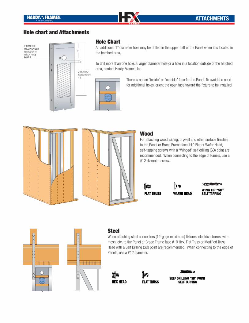
TM
TM
ATTACHMENTS
SELF DRILLING “SD” POINT SELF TAPPING WING TIP “SD”
SELF TAPPING
BUGLE HEAD WAFER HEAD
FLAT TRUSS MODIFIED TRUSS
HEX HEAD
SELF DRILLING “SD” POINT SELF TAPPING WING TIP “SD”
SELF TAPPING
BUGLE HEAD WAFER HEAD
FLAT TRUSS MODIFIED TRUSS
HEX HEAD
SELF DRILLING “SD” POINT SELF TAPPING WING TIP “SD”
SELF TAPPING
BUGLE HEAD WAFER HEAD
FLAT TRUSS MODIFIED TRUSS
HEX HEAD
WoodFor attaching wood, siding, drywall and other surface finishes to the Panel or Brace Frame face #10 Flat or Wafer Head, self-tapping screws with a “Winged” self drilling (SD) point are recommended. When connecting to the edge of Panels, use a #12 diameter screw.
Hole ChartAn additional 1” diameter hole may be drilled in the upper half of the Panel when it is located in the hatched area.
To drill more than one hole, a larger diameter hole or a hole in a location outside of the hatched area, contact Hardy Frames, Inc.
4˝4˝
9˝
1˝
UPPER HALF(PANEL HEIGHT ÷ 2)
3˝ DIAMETERHOLE PROVIDED IN FACE OF 18˝ AND 24˝ WIDE PANELS
There is not an “inside” or “outside” face for the Panel. To avoid the need for additional holes, orient the open face toward the fixture to be installed.
Hole chart and Attachments
SteelWhen attaching steel connectors (12-gage maximum) fixtures, electrical boxes, wire mesh, etc. to the Panel or Brace Frame face #10 Hex, Flat Truss or Modified Truss Head with a Self Drilling (SD) point are recommended. When connecting to the edge of Panels, use a #12 diameter.
SELF DRILLING “SD” POINT SELF TAPPING WING TIP “SD”
SELF TAPPING
BUGLE HEAD WAFER HEAD
FLAT TRUSS MODIFIED TRUSS
HEX HEAD
SELF DRILLING “SD” POINT SELF TAPPING WING TIP “SD”
SELF TAPPING
BUGLE HEAD WAFER HEAD
FLAT TRUSS MODIFIED TRUSS
HEX HEAD
SELF DRILLING “SD” POINT SELF TAPPING WING TIP “SD”
SELF TAPPING
BUGLE HEAD WAFER HEAD
FLAT TRUSS MODIFIED TRUSS
HEX HEAD
1732 Palma Dr., Suite 200, Ventura, California 93003 800 754-3030 www.hardyframe.com
Additional Tools and Publications From Hardy Frames, Inc.
Typical Installation Detail PagesHardy Frames, Inc. provides our Typical Installation Details in plan format. These pages are available in ACAD, pdf, or you may request a hard copy directly from us. The pages are organized by bottom connections, top connections and installations involving floor systems. Any or all of these pages may be attached to your plans as supplemental pages or you can copy selected details as needed.
Installation Guide The Hardy Frame Installation Guide was written specifically for Suppliers and
Installers. This publication provides all HFX-Series model numbers, dimensions, bolt and screw patterns, connectors, installation illustrations, attachments with
self-tapping screws and information regarding Template Kit (HFXTK) and Floor to Floor Connector Kit (HFTC)components.
Moment Frame CatalogIncludes instructions for designing with Hardy Frame® Moment Frames, allowable values, typical Installation details and a Non-Standard form for submittal when project conditions require a custom design.
Braced Wall GuidelinesProvides a summary of Prescriptive Braced Wall Design and recommends the most economical
solution with HFX-Series Panels. Includes recommended model numbers, their Accessory items
and installation illustrations. Also see page 9 of Product Catalog.
The Z4 product line, including the Cinch Nut, CT and T2, are now a part of the Hardy Frames, Inc. family. The Cinch Nut is a self ratcheting device that is designed to main-tain a tight connection in the Z4 continuous "Quick Connect" rod system. The Cinch Nut joins the CT and T2 to offer more design options than any other hold down system and are rated for Tension capacities that range from 5,000 to 60,000 lbs. In addition to continuous rod applications, the T2 can be used as a hold down in conventionally framed shear walls. [email protected]
S H E A R W A L L S Y S T E M