SERIES MODEL MVH-306GH - cessco.us
80
OPERATION AND PARTS MANUAL THIS MANUAL MUST ACCOMPANY THE EQUIPMENT AT ALL TIMES. To find the latest revision of this publication, visit our website at: www.multiquip.com SERIES MODEL MVH-306GH REVERSIBLE PLATE COMPACTOR (HONDA GX270K1SMX2 GASOLINE ENGINE) Revision #4 (08/15/07)
Transcript of SERIES MODEL MVH-306GH - cessco.us

OPERATION AND PARTS MANUAL
THIS MANUAL MUST ACCOMPANY THE EQUIPMENT AT ALL TIMES.
To find the latest revision of thispublication, visit our website at:
www.multiquip.com
SERIESMODEL MVH-306GH
REVERSIBLE PLATE COMPACTOR(HONDA GX270K1SMX2 GASOLINE ENGINE)
Revision #4 (08/15/07)

PAGE 2 — MVH-306GH PLATE COMPACTOR — OPERATION AND PARTS MANUAL — REV. #4 (08/15/07)
PROPOSITION 65 WARNING

MVH-306GH PLATE COMPACTOR — OPERATION AND PARTS MANUAL — REV. #4 (08/15/07) — PAGE 3
NOTES

PAGE 4 — MVH-306GH PLATE COMPACTOR — OPERATION AND PARTS MANUAL — REV. #4 (08/15/07)
TABLE OF CONTENTS
HONDA GX270K1SMX2 GASOLINE ENGINEAir Cleaner Assembly ......................................... 46-47Camshaft Assembly ........................................... 48-49Carburetor Assembly ......................................... 50-51Control Assembly ............................................... 52-53Crankcase Cover Assembly ............................... 54-55Crankshaft Assembly ......................................... 56-57Cylinder Barrel Assembly ................................... 58-59Cylinder Head Assembly .................................... 60-61Fan Cover Assembly .......................................... 62-63Flywheel Assembly ............................................ 64-65Fuel Tank Assembly ........................................... 66-67Ignition Coil Assembly ........................................ 68-69Muffler Assembly ............................................... 70-71Piston Assembly ................................................. 72-73Recoil Starter Assembly..................................... 74-75Labels Assembly ................................................ 76-77
Terms and Conditions Of Sale — Parts .................. 78
Specification and part number aresubject to change without notice.
MIKASA MVH-306GHREVERSIBLE PLATECOMPACTORProposition 65 Warning ..............................................2Table Of Contents ......................................................4Parts Ordering Procedures ........................................5Safety Message Alert Symbols .............................. 6-7Rules for Safe Operation ....................................... 8-9Operation and Safety Decals ...................................10Specifications ...........................................................11Dimensions ..............................................................12Features ...................................................................13Plate Compactor Components .................................14Engine Components ................................................15Pre-Inspection .................................................... 16-17Operation ........................................................... 18-21Maintenance ...................................................... 22-25Troubleshooting (Engine) .........................................26Troubleshooting (Compactor) ..................................27
PARTS ILLUSTRATIONSExplanation Of Code In Remarks Column ...............28Suggested Spare Parts ............................................29Nameplate and Decals ....................................... 30-31Vibrating Plate Assembly ................................... 32-33Base and Engine Assembly ............................... 34-37Vibrator Assembly .............................................. 38-39Control Handle Assembly .................................. 40-43Hand Pump Assembly ........................................ 44-45

MVH-306GH PLATE COMPACTOR — OPERATION AND PARTS MANUAL — REV. #4 (08/15/07) — PAGE 5
ww
w.m
ultiq
uip
.com
Ordering parts has never been easier!Choose from three easy options:
WE ACCEPT ALL MAJOR CREDIT CARDS!
When ordering parts, please supply:❒❒❒❒❒ Dealer Account Number
❒❒❒❒❒ Dealer Name and Address
❒❒❒❒❒ Shipping Address (if different than billing address)
❒❒❒❒❒ Return Fax Number❒❒❒❒❒ Applicable Model Number
❒❒❒❒❒ Quantity, Part Number and Description of Each Part
❒❒❒❒❒ Specify Preferred Method of Shipment:✓ UPS/Fed Ex ✓ DHL
■ Priority One ✓ Truck■ Ground■ Next Day■ Second/Third Day
All orders are treated as Standard Ordersand will ship the same day if received priorto 3PM PST.
If you have an MQ Account, to obtain aUsername and Password, E-mail us at:[email protected].
To obtain an MQ Account, contact yourDistrict Sales Manager for more information.
Order via Internet (Dealers Only):Order parts on-line using Multiquip’s SmartEquip website!
■ View Parts Diagrams■ Order Parts■ Print Specification Information
Note: Discounts Are Subject To Change
Goto www.multiquip.com and click on
Order Parts to log in and save!
Use the internet and qualify for a 5% Discounton Standard orders for all orders which includecomplete part numbers.*
Order via Fax (Dealers Only):All customers are welcome to order parts via Fax.Domestic (US) Customers dial:1-800-6-PARTS-7 (800-672-7877)
Fax your order in and qualify for a 2% Discounton Standard orders for all orders which includecomplete part numbers.*
Order via Phone: Domestic (US) Dealers Call:1-800-427-1244
Best Deal!
International Customers should contacttheir local Multiquip Representatives forParts Ordering information.
Non-Dealer Customers:Contact your local Multiquip Dealer forparts or call 800-427-1244 for help inlocating a dealer near you.
Note: Discounts Are Subject To Change
Effective:January 1st, 2006
PARTS ORDERING PROCEDURES
PAGE 6 — MVH-306GH PLATE COMPACTOR — OPERATION AND PARTS MANUAL — REV. #4 (08/15/07)
MVH-306GH — SAFETY MESSAGE ALERT SYMBOLS
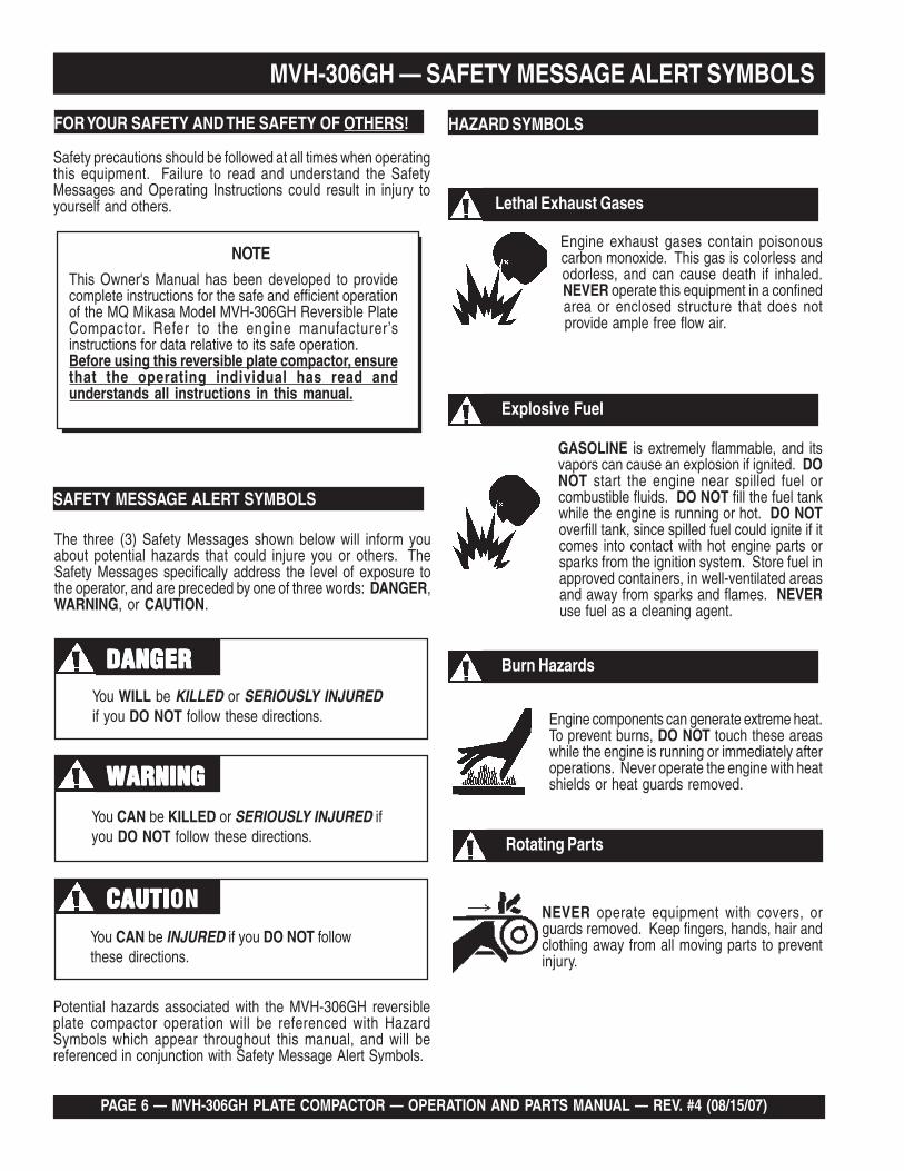
Safety precautions should be followed at all times when operatingthis equipment. Failure to read and understand the SafetyMessages and Operating Instructions could result in injury toyourself and others.
FOR YOUR SAFETY AND THE SAFETY OF OTHERS!
This Owner's Manual has been developed to providecomplete instructions for the safe and efficient operationof the MQ Mikasa Model MVH-306GH Reversible PlateCompactor. Refer to the engine manufacturer’sinstructions for data relative to its safe operation.Before using this reversible plate compactor, ensurethat the operating individual has read andunderstands all instructions in this manual.
NOTE
SAFETY MESSAGE ALERT SYMBOLS
The three (3) Safety Messages shown below will inform youabout potential hazards that could injure you or others. TheSafety Messages specifically address the level of exposure tothe operator, and are preceded by one of three words: DANGER,WARNING, or CAUTION.
HAZARD SYMBOLS
Engine exhaust gases contain poisonouscarbon monoxide. This gas is colorless andodorless, and can cause death if inhaled.NEVER operate this equipment in a confinedarea or enclosed structure that does notprovide ample free flow air.
Potential hazards associated with the MVH-306GH reversibleplate compactor operation will be referenced with HazardSymbols which appear throughout this manual, and will bereferenced in conjunction with Safety Message Alert Symbols.
GASOLINE is extremely flammable, and itsvapors can cause an explosion if ignited. DONOT start the engine near spilled fuel orcombustible fluids. DO NOT fill the fuel tankwhile the engine is running or hot. DO NOToverfill tank, since spilled fuel could ignite if itcomes into contact with hot engine parts orsparks from the ignition system. Store fuel inapproved containers, in well-ventilated areasand away from sparks and flames. NEVERuse fuel as a cleaning agent.
Explosive Fuel
Lethal Exhaust Gases
Burn Hazards
Engine components can generate extreme heat.To prevent burns, DO NOT touch these areaswhile the engine is running or immediately afteroperations. Never operate the engine with heatshields or heat guards removed.
Rotating Parts
NEVER operate equipment with covers, orguards removed. Keep fingers, hands, hair andclothing away from all moving parts to preventinjury.
You WILL be KILLED or SERIOUSLY INJUREDif you DO NOT follow these directions.
You CAN be KILLED or SERIOUSLY INJURED ifyou DO NOT follow these directions.
You CAN be INJURED if you DO NOT followthese directions.
CAUTICAUTICAUTICAUTICAUTION
DANGERDANGERDANGERDANGERDANGER
WARNINGWARNINGWARNINGWARNINGWARNING

MVH-306GH PLATE COMPACTOR — OPERATION AND PARTS MANUAL — REV. #4 (08/15/07) — PAGE 7
Accidental Starting
MVH-306GH — SAFETY MESSAGE ALERT SYMBOLS
ALWAYS place the engine ON/OFF switch inthe OFF position, when the reversible platecompactor is not in use.
Respiratory Hazard
ALWAYS wear approved respiratoryprotection.
Equipment Damage Messages
Other important messages are provided throughout this manualto help prevent damage to your reversible plate compactor,other property, or the surrounding environment.ALWAYS wear approved eye and hearing
protection.
Sight and Hearing hazard
This reversible plate compactor, other property,or the surrounding environment could bedamaged if you do not follow instructions.

PAGE 8 — MVH-306GH PLATE COMPACTOR — OPERATION AND PARTS MANUAL — REV. #4 (08/15/07)
MVH-306GH — RULES FOR SAFE OPERATION
■ ALWAYS refuel in a well-ventilated area, away from sparksand open flames.
■ ALWAYS use extreme caution when working with flammableliquids. When refueling, stop the engine and allow it to cool.DO NOT smoke around or near the machine. Fire orexplosion could result from fuel vapors, or if fuel is spilled ona hot engine.
■ NEVER operate the reversible plate compactor in anexplosive atmosphere or nearcombustible materials. An explosion orfire could result causing severe bodilyharm or even death.
■ Topping-off to filler port is dangerous, asit tends to spill fuel.
■ ALWAYS store the reversible plate compactor in a clean, drylocation out of the reach of children.
■ NEVER run engine without air cleaner. Severe enginedamage may occur.
■ NEVER leave the reversible plate compactor unattended,turn off engine.
■ CAUTION must always be observed while servicing thisreversible plate compactor. Rotating parts can cause injury ifcontacted.
■ DO NOT leave reversible plate compactor with enginerunning. Use chock blocks if parking reversible platecompactor on a grade.
■ NEVER touch the hot exhaust manifold,muffler or cylinder. Allow these parts tocool before servicing engine orreversible plate compactor.
■ The engine of this reversible plate compactor requires anadequate free flow of coolingair. NEVER operate thereversible plate compactor inany enclosed or narrow areawhere free flow of the air isrestricted. If the air flow isrestricted it will cause seriousdamage to the reversible platecompactor or engine and maycause injury to people and property. Remember thereversible plate compactor’s engine gives off DEADLY gases.
■ High Temperatures – Allow the engine to cool before addingfuel or performing service and maintenance functions. Contactwith hot components can cause serious burns.
The following safety guidelines should always be used whenoperating theMQ Mikasa MVH-306GH Reversible PlateCompactor:
GENERAL SAFETY
■ DO NOT operate or service this equipment beforereading this entire manual.
■ This equipment should not be operated bypersons under 18 years of age.
■ NEVER operate this equipment without properprotective clothing, shatterproof glasses, steel-toed boots and other protective devices requiredby the job. ALWAYS wear slip resistant safetyshoes or boots.
■ NEVER operate this equipment when not feelingwell due to fatigue, illness or taking medicine.
■ NEVER operate this equipment under theinfluence or drugs or alcohol.
■ NEVER use accessories or attachments,which are not recommended by Multiquip for this equipment.Damage to the equipment and/or injury to user may result.
■ Manufacturer does not assume responsibility for any accidentdue to equipment modifications.
■ Whenever necessary, replace nameplate, operation and safetydecals when they become difficult read.
■ ALWAYS wear proper respiratory (mask), hearing and eyeprotection equipment when operating the reversible platecompactor.
CAUTION
Failure to follow instructions in this manual may lead to seriousinjury or even death! This equipment is to be operated by trainedand qualified personnel only! This equipment is for industrialuse only.

MVH-306GH PLATE COMPACTOR — OPERATION AND PARTS MANUAL — REV. #4 (08/15/07) — PAGE 9
MVH-306GH — RULES FOR SAFE OPERATION
Maintenance Safety■ NEVER lubricate components or attempt service on a
running machine.
■ ALWAYS allow the machine a proper amount of time tocool before servicing.
■ Keep the machinery in proper running condition.
■ Fix damage to the machine immediately and always replacebroken parts.
■ Dispose of hazardous waste properly. Examples ofpotentially hazardous waste are used motor oil, fuel andfuel filters.
■ DO NOT use food or plastic containers to dispose ofhazardous waste.
■ DO NOT pour waste, oil or fuel directly onto the ground,down a drain or into any water source.
■ NEVER disconnect any "emergency or safety devices".These devices are intended for operator safety. Disconnectionof these devices can cause severe injury, bodily harm or evendeath! Disconnection of any of these devices will void allwarranties.
Transporting
■ Always shutdown engine before transporting.
■ Tighten fuel tank cap securely and close fuel cock to preventfuel from spilling.
■ Drain fuel when transporting compactor over long distancesor bad roads.
■ Always tie-down the compactor during transportation bysecuring the compactor's guard frame with an appropriatetie-down.
Loading and Unloading■ Before lifting, make sure that machine parts (hook and
vibration insulator) are not damaged and screws are notloosened or lost.
■ ALWAYS make sure crane or lifting device has been properlysecured to the lifting bale of compactor.
■ NEVER lift the machine while the engine is running.
■ Use a reliable chain, cable or strap of adequate liftingcapacity.
■ NEVER allow any person or animal to stand underneath themachine while lifting.
■ Use a crane with a one point suspension hook and lift straightupwards, or use forklift to load and unload the compactor. Askilled crane operator is required to perform the job.
■ ALWAYS use the lifting bale (Figure 1) on the machine whenlifting is required. DO NOT use any other part of the machinefor lifting.
■ ALWAYS lift the machine vertically.
■ Try not to lift machine to unnecessary heights.
Emergencies
■ ALWAYS know the location of thenearest fire extinguisher.
Figure 1. Lifting the Compactor
■ ALWAYS know the location of the nearestand first aid kit.
■ In emergencies, always know the location of thenearest phone or keep a phone on the job site.Also know the phone numbers of the nearestambulance, doctor and fire department. Thisinformation will be invaluable in the case of anemergency.

PAGE 10 — MVH-306GH PLATE COMPACTOR — OPERATION AND PARTS MANUAL — REV. #4 (08/15/07)
MVH-306GH — OPERATION AND SAFETY DECALS
Figure 2. Operation and Safety Decals
Figure 2 displays the operation and safety decals as they appear on the reversible plate compactor. Should any of these decalsbecome damaged or unreadable, contact the Multiquip Parts Department for a replacement set.

MVH-306GH PLATE COMPACTOR — OPERATION AND PARTS MANUAL — REV. #4 (08/15/07) — PAGE 11
MVH-306GH —SPECIFICATIONS
etalPelbisreveRHG603-HVM.1elbaTsnoitacificepSrotcapmoC
ecroFlagufirtneC )gk206,4(bl521,01
ycneuqerFnoitarbiV )zH07(mpv004,4
deepSgnilevarT )nim/m32ot0(nim/tf57ot0
)WxL(eziSetalP )mc63.68x27.54(ni43x81
)WxL(eziSetalPlanretxEhtiW )mc63.68x69.06(ni43x42
)snoisnetxeon(noitcapmoCfoaerA.xaM )sretem.qs750,2(.tf.qs057,6
htgneLllarevO )mm0751(ni8.16
htdiWllarevO )mm754(ni0.81
)eldnahhtiw(thgieHllarevO )mm0211(ni1.44
)eldnahtuohtiw(thgieHllarevO )mm508(ni7.13
SD/DthgieWgnitarepO )gk603(.sbl376
)setalpnoisnetxehtiw(thgieWgnitarepO )gk123(.sbl607
snoitacificepSenignE.2elbaT
enignE
ledoM 2XMS1K072XGADNOH
epyT,rednilyCelgniS,ekortS-4
enignEenilosaG,VHO
ekortSXeroB.ni3.2X.ni0.3
).mm85xmm77(
tnemecalpsiD mc072(ni-uc5.61 3)
tuptuOxaM .M.P.R0063@)WK7.6(.P.H0.9
yticapaCknaTleuF )sretil0.6(snollag95.1
leuF enilosaGelibomotuAdedaelnU
yticapaCliOebuL )sretil1.1(strauq61.1
dohteMlortnoCdeepS epyTthgiew-ylFlagufirtneC
dohteMgnitratS tratSlioceR
noisnemiD)HxWxL(
.ni1.61X9.61x0.41).mm014X034X553(
thgieWteNyrD ).gK52(sbl1.55

PAGE 12 — MVH-306GH PLATE COMPACTOR — OPERATION AND PARTS MANUAL — REV. #4 (08/15/07)
MVH-306GH — DIMENSIONS
Figure 3. MVH-306GH Reversible Plate Compactor Dimensions
snoisnemiD.3elbaT
.FER SNOISNEMID
A ).mc6.431(.ni35
B ).mc64(.ni81
C ).mc68(.ni43
D ).mc261(.ni8.36
E ).mc5.08(7.13

MVH-306GH PLATE COMPACTOR — OPERATION AND PARTS MANUAL — REV. #4 (08/15/07) — PAGE 13
MVH-306GH— FEATURES
Plate Compactor
The Mikasa MVH-306GH is a walk behind, reversible platecompactor designed for the compaction of sand, clay andasphalt. This plate compactor is a powerful compacting toolcapable of applying a tremendous force in consecutive highfrequency vibrations to a soil surface. Its applications includesoil compacting for road, embankments and reservoirs as wellas backfilling for gas pipelines, water pipelines and cableinstallation work.
Vibratory Plates
The vibratory plates of the MVH-306GH produce low amplitudehigh frequency vibrations, designed to compact granular soils.
The resulting vibrations cause forward motion. The engine andhandle are vibration isolated from the vibrating plate. The heavierthe plate, the more compaction force it generates.
Reversible Vibratory Plates
Reversible vibratory plates have two eccentric weights that allowa smooth transition for forward and reverse travel, plus increasedcompaction force as the result of dual weights.
Due to their weight and force, reversible plates are ideal forsemi-cohesive soils.
Frequency/Speed
The compactor's vibrating plate maximum frequency is 4400vpm (vibrations per minute). The forward and reverse travel speedof the compactor is approximately 75 ft./minute (23 meters/minute).
Engine
The Mikasa MVH-306GH Plate Compactor is equipped with aGX270K1-SMX2 (recoil start) gasoline engine.
Controls
Before starting the MVH-306GH Plate Compactor, identify andunderstand the function of the controls and components asindicated in Figure 4.

PAGE 14 — MVH-306GH PLATE COMPACTOR — OPERATION AND PARTS MANUAL — REV. #4 (08/15/07)
MVH-306GH— PLATE COMPACTOR COMPONENTS
Figure 4. MVH-306GH Reversible PlateCompactor Components
Figure 4 illustrates the location of the major components for theMVH-306GH Reversible Plate Compactor. The function of eachcomponent is described below:
1. Hand Grip – When operating the compactor use this handgrip to maneuver the compactor.
2. Forward & Reverse Lever – Push the lever forward, thecompactor will move in a forward direction, pull the leverbackwards, the compactor will move in backwards direction.Placing the lever in the middle (midway) will cause thecompactor not to move (neutral).
3. Handle Bar – When operating the compactor, this handleis to be in the downward position. When the compactor isto be stored, move the handle bar to the upright position.
4. Guard Hook - Used to lift the machine with crane or otherlifting device.
5. Stopper - Locks the handle in place in the upward positionfor stowing.
6. Engine – This plate compactor uses a GX270K1-SMX2gasoline engine. Refer to the owner’s manual for engineinformation and related topics.
7. Belt Cover – Remove this cover to gain access to the V-belts. NEVER run the compactor without the V-belt cover. Ifthe V-belt cover is not installed, the possibility exist thatyour hand may get caught between the V-belt and clutch,thus causing serious injury and bodily harm.
8. Base Plate – Designed to compact sand, clay, and asphalt.
9. Oil Reservoir – Fill with Shell Tellus Oil 46 or equivalentgrade hydraulic oil.
10. Vibration Case – Encloses the eccentric, gears andcounter weights.
11. Hydraulic Cylinder – Activated by moving the travel lever.The cylinder controls the direction of movement by the platecompactor.
12. Shock Absorber – Protects plate compactor from damageby absorbing vibration during operation.
13. Throttle Lever – Controls speed of the plate compactor.Place straight vertically to start, push fully counterclockwisefor full throttle and fully clockwise to stop plate compactor.
14. Rubber Cover – Lift this rubber cover to gain access tothe fuel tank.

MVH-306GH PLATE COMPACTOR — OPERATION AND PARTS MANUAL — REV. #4 (08/15/07) — PAGE 15
MVH-306GH— ENGINE COMPONENTS
Figure 5. Honda GX270 Engine ComponentsINITIAL SERVICING
The engine (Figure 5) must be checked for proper lubrication andfilled with fuel prior to operation. Refer to the manufacturers enginemanual for instructions & details of operation and servicing. Theengine shown above is a HONDA engine, operation for othertypes of engines may vary somewhat.
1. Fuel Filler Cap – Remove this cap to add unleadedgasoline to the fuel tank. Make sure cap is tightenedsecurely. DO NOT over fill.
DANGER
Adding fuel to the tank should be done only whenthe engine is stopped and has had an opportunityto cool down. In the event of a fuel spill, DO NOT
attempt to start the engine until the fuel residue has been completelywiped up, and the area surrounding the engine is dry.
2. Throttle Lever – Used to adjust engine RPM speed (leveradvanced forward SLOW, lever back toward operatorFAST).
3. Engine ON/OFF Switch – ON position permits enginestarting, OFF position stops engine operations.
4. Recoil Starter (pull rope) – Manual-starting method. Pullthe starter grip until resistance is felt, then pull briskly andsmoothly.
5. Fuel Valve Lever – OPEN to let fuel flow, CLOSE to stopthe flow of fuel.
6. Choke Lever – Used in the starting of a cold engine, or incold weather conditions. The choke enriches the fuelmixture.
7. Air Cleaner – Prevents dirt and other debris from enteringthe fuel system. Remove wing-nut on top of air filtercannister to gain access to filter element.
8. Spark Plug – Provides spark to the ignition system. Setspark plug gap to 0.6 - 0.7 mm (0.028 - 0.031 inch) Cleanspark plug once a week.
9. Muffler – Used to reduce noise and emissions.
Engine components can generate extreme heat.To prevent burns, DO NOT touch these areaswhile the engine is running or immediately after
operating. NEVER operate the engine with the muffler removed.
10. Fuel Tank – Holds unleaded gasoline. For additionalinformation refer to engine owner's manual.
Operating the engine without an air filter, with adamaged air filter, or a filter in need ofreplacement will allow dirt to enter the engine,causing rapid engine wear.
WARNING

PAGE 16 — MVH-306GH PLATE COMPACTOR — OPERATION AND PARTS MANUAL — REV. #4 (08/15/07)
MVH-306GH — PRE-INSPECTION
Checking Engine Oil Level
1. To check the engine oil level, place the compactor on securelevel ground with the engine stopped.
2. Remove the dipstick from the engine oil filler hole (Figure 6)and wipe it clean.
3. Insert and remove the dipstick without screwing it into thefiller neck. Check the oil level shown on the dipstick.
NEVER operate the compactor in a confinedarea or enclosed area structure that does notprovide ample free flow of air.
ALWAYS wear approved eye and hearingprotection before operating the compactor.
Before Starting
1. Read safety instructions at the beginningof manual.
2. Familiarize yourself with the operatingand control elements of the machineand the working environment. This includes obstacles inthe working area, bearing capacity of the ground and thenecessary safety provisions.
3. Check the air filter for dirt and dust. If air filter is dirty, replaceair filter with a new one as required.
4. Check fastening nuts and bolts for tightness. Loose threadsmay cause damage to the machine when vibrating.
5. Understand the geographical features and regulations ofthe job site.
6. Clean the compactor, removing dirt and dust. Particularly,the bottom of the plate, engine cooling air inlet.
Figure 6. Engine Oil Dipstick Removal
4. If the oil level is low (Figure 7), fill to the edge of the oil fillerhole with the recommended oil type (Table 4). Maximum oilcapacity is 1.16 quarts (1.10 liters).
epyTliO.4elbaT
nosaeS erutarepmeT epyTliO
remmuS rehgiHroC°52 03-W01EAS
llaF/gnirpS C°01~C°52 02/03-W01EAS
retniW rewoLroC°0 01-W01EAS
Checking the Hydraulic Oil Level
1. To check the engine oil level, place the compactor on securelevel ground with the engine stopped.
2. Remove the hydraulic oil breather cap located at the top of thehydraulic oil tank (Figure 8).
3. Using a 24 mm wrench, remove the hydraulic oil filler plug.
3. Visually inspect to determine if hydraulic oil level is low. If oillevel is low add Shell Tellus 46 hydraulic oil or equivalentthrough the hand pump oil filler port.
Figure 8. Hydraulic Oil Filler Plug Removal
CAUTION
Figure 7. Engine Oil Level

MVH-306GH PLATE COMPACTOR — OPERATION AND PARTS MANUAL — REV. #4 (08/15/07) — PAGE 17
Checking The Fuel1. Remove the fuel cap located on top of fuel tank.2. Visually inspect to see if fuel level is low. If fuel is low, replenish
with unleaded gasoline. (Figure 11).3. When refueling, be sure to use a strainer for filtration. DO NOT
top-off fuel. Wipe up any spilled fuel.
Figure 11. Refueling
Fuel spillage on a hot engine can cause a fire or explosion.If fuel spillage occurs, wipe up the spilled fuel completely toprevent fire hazards. NEVER! smoke around or near thecompactor.
Explosive Fuel
Diesel fuel is highly flammable and can be dangerous ifmishandled. DO NOT smoke while refueling. DO NOT attemptto refuel the compactor if the engine is hot! or running.
DANGER
MVH-306GH — PRE-INSPECTION
4. When adding hydraulic oil, only fill to the specified oil level asmarked on the front of the hydraulic oil tank (Figure 9). DONOT overfill.
Checking the Air Cleaner
1. Loosen the wing nut and remove the air cleaner cover asshown in Figure 10.
2. Remove the paper filter element and inspect it for signs ofwear or dirt. If paper filter element is dirty, clean or replaceelement.
Figure 9. Oil Tank (Front View)
Figure 10. Air Cleaner Element
DANGER
DO NOT overfill hydraulic oil tank. This could cause oil leaksand sluggish operation. Clean cap and surrounding area beforeopening to prevent dirt from entering oil tank.
CAUTION

PAGE 18 — MVH-306GH PLATE COMPACTOR — OPERATION AND PARTS MANUAL — REV. #4 (08/15/07)
Adjusting Handle Height
The height of the handle is adjustable for your comfort .
1. Loosen the butterfly screw (Figure 13).
2. Turn the grip clockwise to raise the handle or counterclock-wise to lower the handle.
3. When the handle is raised to the desired height, tighten thebutterfly screw.
MVH-306GH — OPERATION
Figure 13. Handle Adjustment
STARTING THE ENGINE
DO NOT attempt to operate the compactoruntil the Safety, General Information andInspection sections of this manual havebeen read and thoroughlyunderstood.
This section is intended to assist theoperator with the initial start-up of the compactor. It is extremelyimportant that this section be read carefully before attempting touse the compactor in the field.
Refer to Figure 4 for the location of controls and components.
Releasing the Handle
1. Pull the handle release pin, (Figure 12) then push down onthe hand grip to release the handle.
Figure 12. Handle Release Pin
CAUTION
Starting the Engine (HONDA engine)
1. Place the engine fuel valve lever (Figure 14) to the "ON"position.
2. Move the throttle lever to the START position (Figure 15).
Figure 14. Engine Fuel Valve Lever (ON Position)
Figure 15. Throttle Lever (Start Position)

MVH-306GH PLATE COMPACTOR — OPERATION AND PARTS MANUAL — REV. #4 (08/15/07) — PAGE 19
TRAVELING
Make sure to follow all safety rules referenced in the safety sectionof this manual before operating compactor. Keep work areaclear of debris and other objects that could cause damage to thecompactor or bodily harm.
Figure 20. Throttle Lever (Fast)
1. Grasp the compactor's hand grip (Figure 20), and move theengine throttle lever (Figure 20) quickly to the fast position.
2. With the throttle lever in the fast position, the engine speedshould be around 3,600 RPM, therefore engaging the cen-trifugal clutch.
CAUTION
MVH-306GH — OPERATION3. Place the choke lever (Figure 16) in the "OPEN " position
if starting a cold engine.
4. Place the choke lever (Figure 17) in the "CLOSED " positionif starting a warm engine or the temperature is warm.
Figure 16. Engine Choke Lever (Open)
Figure 17. Engine Choke Lever (Closed)
6. Grasp the starter grip (Figure 19) and slowly pull it out. Theresistance becomes the hardest at a certain position, corre-sponding to the compression point. Pull the starter grip brisklyand smoothly for starting.
7. If the engine has started, slowly return the choke lever(Figure 17) to the CLOSED position. If the engine has notstarted repeat steps 1 through 6.
Figure 19. Starter Grip
8. Before the compactor is placed into operation, run the enginefor several minutes. Check for fuel leaks, and noises thatwould be associated with a loose component.
5. Place the engine ON/OFF switch (Figure 18) in the "ON "position.
Figure 18. Engine ON/OFF Switch (ON Position)
ALWAYS move the throttle lever quickly withouthesitation, because increasing the enginespeed slowly causes the clutch to slip.

PAGE 20 — MVH-306GH PLATE COMPACTOR — OPERATION AND PARTS MANUAL — REV. #4 (08/15/07)
STOWING THE HANDLE
1. Push up the handle upward (Figure 25) until the handle locksin place.
Figure 25. Stowing the Handle
Normal Shutdown
1. Return the throttle lever to the START position (Figure 15).Allow the machine to cool down for 2 to 3 minutes.
2. Place the travel lever in the NEUTRAL position.
3. Place the throttle lever in the STOP position (Figure 22) to stopthe engine.
4. Turn the engine ON/OFF switch to the “OFF” position (Figure 23).
5. Place the fuel shut-off lever (Figure 24) in the OFFposition.
Figure 22. Throttle Lever (Stop)
Emergency Shutdown
1. For a recoil start type engine, move the throttle lever quicklyto the STOP position.
MVH-306GH—OPERATION
Figure 21. Travel Lever
3. To make the compactor move in the forward direction pushthe travel lever ( Figure 21) forward.
4. To make the compactor move in the reverse direction pull thetravel lever ( Figure 21) backwards.
5. Firmly gasp the compactor's hand grip, the compactor willbegin moving in the desired position when the direction leverhas been placed in the desired position.
6. Slowly walk behind the compactor and be on the lookout forany large objects or foreign matter that might cause damageto the compactor or bodily injury.
7. If travel lever is placed in the neutral position, the machine willvibrate in place.
8. To move the compactor laterally, hold the hand grip firmly andswing compactor. DO NOT swing compactor while grippingthe travel lever.
Figure 24. Fuel Valve Lever (OFF)
Figure 23. Engine ON/OFF Switch (OFF)

MVH-306GH PLATE COMPACTOR — OPERATION AND PARTS MANUAL — REV. #4 (08/15/07) — PAGE 21
MVH-306GH — MAINTENANCE
Inspection and Maintenance Service Tables.
1. To make sure your plate compactor is always in goodworking condition before using, carry out the maintenanceinspection in accordance with Tables 5 through 7.
Daily Service
Check for leakage of fuel or oil.
Check for loose screws including tightness. See Table 7below (tightening torque ), for retightening:
Remove soil and clean the bottom of compaction plate.
Check hand pump, piping and hose for any leakage. Aloosened hydraulic hose can be a cause for leakage. Checkhydraulic hose connections with wrench applied fortightness.
Check engine oil.
Inspection and other services should always be carried out onhard and level ground with the engine shutdown.
These inspection intervals are for operation under normalconditions. Adjust your inspection intervals based on the numberhours plate compactor is in use, and particular workingconditions.
Fuel piping and connections should be replaced every 2 years.
EUQROTGNINETHGIT.7ELBATretemaiD)mc/gk.ni(
lairetaM mm6 mm8 mm01 mm21 mm41 mm61 mm81 mm02
T4 07 051 003 005 057 001,1 004,1 000,2
T8-6 001 052 005 008 003,1 000,2 007,2 008,3
T11 051 004 008 002,1 000,2 009,2 002,4 006,5
* 001 ~003053
~056007
)munimulafositrap-retnuocesacnI(*)dednahthgirllaeraenihcamsihthtiwesunisdaerhT(
.wercsdna,tlobhcaenodekramsilairetamfoytilauqdnalairetaM
CAUTIONCAUTION
CAUTION
HG603-HVM.6ELBAT kcehCenignE
METI NOITAREPOFOSRUOH
kcehCgulPkrapS )keewyreve(sruoh04yrevE
kaeLleuFroliO )yadyreve(sruoh8yrevE
gninetsaFfossenthgiTsdaerhT
)yadyreve(sruoh8yrevE
dnakcehCliOenignEtnemhsinelpeR
)yadyreve(sruoh8yrevEmumixamdeificepsothsinelpeR(
)level
tnemecalpeRliOenignEot05yrevenehtsruoh52tsrifretfA
sruoh001
gninaelCretliFriA sruoh001yrevE
.kcehcenignenosliatedroflaunamenigneetarapeseeS
HG603-HVM.5ELBAT NOITCEPSNIENIHCAM
METIFOSRUOHNOITAREPO
SKRAMER
gnissiMroesooLswercS
sruoh8yrevE)yadyreve(
straPdegamaDsruoh8yrevE
)yadyreve(
gnillortnoCfonoitcnuFtraPmetsyS
sruoh8yrevE)yadyreve(
kaeLmetsySciluardyH sruoh001yrevE 12egapeeS
kcehCliOrotarbiV sruoh001yrevE 32egapeeS
liOrotarbiVtnemecalpeR
sruoh003yrevE 32egapeeS
kcehCliOciluardyH sruoh001yrevE 32egapeeS
liOciluardyHtnemecalpeR
002retfatsriFyreveneht,sruoh
sruoh000,132egapeeS
kcehC)hctulc(tleb-V sruoh002yrevE 22egapeeS
kcehCyrettaB sruoh001yrevE 42egapeeS

PAGE 22 — MVH-306GH PLATE COMPACTOR — OPERATION AND PARTS MANUAL — REV. #4 (08/15/07)
MVH-306GH — MAINTENANCE
NEVER attempt to check the V-belt with the engine running.Severe injury can occur if your hand gets caught between the V-belt and the clutch (Figure 29). Always use safety gloves.
Figure 29. V-Belt Hazard
CLUTCH
PULLEY
VIBRATOR
PULLEY
CAUTION
Engine Oil Replacement
1. Replace engine oil, first in 25 hours of operation and every50 to 100 hours afterwards.
2. Drain the engine oil when the oil is warm as shown inFigure 27.
3. Remove the oil drain bolt and sealing washer and allowthe oil to drain into a suitable container.
4. Replace engine oil with recommended type oil as listedin Table 4. Engine oil capacity is 1.16 quarts (1.1 liters).DO NOT overfill.
5. Install drain bolt with sealing washer and tighten se-curely.
Figure 27. Engine Oil (Draining)
Spark Plug
1. Remove and clean the spark plug (Figure 26).
2. Adjust the spark gap to 0.028 ~0.031 inch (0.6~0.7 mm). Thisunit has electronic ignition, which requires no adjustments.
Figure 26. Spark Plug Gap
Air Filter
1. Remove the air cleaner cover and foam filter element asshown in Figure 28.
2. Tap the paper filter element (Figure 28) several times on ahard surface to remove dirt, or blow compressed air [notexceeding 30 psi (207 kPa, 2.1 kgf/cm2)] through the filterelement from the air cleaner case side. NEVER brush off dirt.Brushing will force dirt into the fibers. Replace the paper filterelement if it is excessively dirty.
3. Clean foam element in warm, soapy water or nonflammablesolvent. Rinse and dry thoroughly. Dip the element in cleanengine oil and completely squeeze out the excess oil from theelement before installing.
Figure 28. Engine Air Filter

MVH-306GH PLATE COMPACTOR — OPERATION AND PARTS MANUAL — REV. #4 (08/15/07) — PAGE 23
Reinstalling the V-belt
Engage V-belt to lower vibrator pulley and push the V-belt to leftside of upper clutch and, in the same manner as in removal,rotate offset wrench clockwise so that the V-belt goes back on.
Replacing the V-belt
Remove the belt cover. Engage an offset wrench 3/4”(19 mm) orthe like to vibrator pulley (lower) fastening bolt. Engage wastecloth or the like at midway of V-belt on the left side and whilepulling it back strongly, rotate the offset wrench clockwise so thatthe V-belt will come off.
Checking Clutch
Check the clutch simultaneously with V-belt checking. With beltcover removed, check outer drum of the clutch for seizure and"V" groove for wear or damage with your eyes. Clean the "V"groove as necessary. Wear of lining or shoe should be checkedwith running check. If the shoe is worn, power transmissionbecomes deficient and slipping will result.
Replacing Clutch
Remove V-belt. Remove bolt at engine power output by giving ashock to an engaged wrench (tapping with hammer or thelike)and rotating bolt counterclockwise. Remove clutch with apulley extractor. To reinstall, reverse the procedure.
Whenever the compactor's vibration becomes weak or lost duringnormal operation regardless of operation hours, check the V-beltand clutch immediately.
Figure 30. V-Belt Check
CAUTION
Checking and Replacing the V-Belt and Clutch
1. After 200 hours of operation, remove the belt cover to checkthe V-belt tension (Figure 30). Tension is proper if the beltbends about 3/8”(10 mm) when depressed strongly withfinger between shafts. Loose or worn V-belts reduces powertransmission efficiency, causing weak compaction andreduces the life of the belt itself.
MVH-306GH — MAINTENANCE
Figure 31. Vibrator Oil Drain and Check Plugs
Vibrator Oil Level Check
1. In every 100 hours of operation, with the machine positionedhorizontally, use a 3/4” (19 mm) wrench and remove vibratoroil level check plug (Figure 31). Visually inspect and see ifvibrator oil level is up to filler port. Be sure to clean areaaround check hole to prevent dirt and dust from entering.
Draining Vibrator Oil
1. Replace vibrator oil after first 200 hours and in every 1,000hours of operation.
2. Position handle bar vertically (storage position).
3. Using a 14 mm wrench remove the vibrator oil drain plug(Figure 31) from the vibrating plate assembly.
Always clean the area around the vibrator oil level check plugbefore removing oil check plug. This will prevent dirt and debrisfrom entering the system.
CAUTION
For draining oil through level check hole, havethe machine inclined with a sleeper or the likeplaced under the compaction plate on oppositeside.
4. After vibrator oil has been completely drained from machine,fill with 10W-30 motor oil to the appropriate safe operatinglevel (Figure 31).
5. Reinstall drain plug into vibrating plate assembly. Apply sealtape or Loctite #575 to thread portion of drain plug.
Draining Hydraulic Oil
1. Disconnect the hydraulic hose connected to the hydraulicoil cylinder (Figure 32).

PAGE 24 — MVH-306GH PLATE COMPACTOR — OPERATION AND PARTS MANUAL — REV. #4 (08/15/07)
Troubleshooting
See Tables 8 (engine) and 9 (plate compactor) on proceedingpages for engine and plate compactor troubleshooting guide.
LONG TERM STORAGE
When storing your compactor for long periods do the following:
Run the engine at idle speed for 3-5 minutes.Stop the engine. Drain the engine crankcase oil while theengine is still warm. Fill engine crankcase with fresh oil.Wipe any oil or dirt that may have accumulated on thecompactor.Store compactor in a cool dry place out of reach of children
and unauthorized personnel..
MVH-306GH—MAINTENANCE
Make sure hydraulic oil is at a normal safe operating level. DONOT over fill. Over filling (excessive oil) will cause excess oil toblow out of breather plug.
3. Loosen bleeder plug located at top of hydraulic cylinder onside of vibrator (Figure 35). Air remaining in the circuit willbe forced out of the bleeder plug. Once all air has beenpurged from the hydraulic system, tighten bleeder plugsecurely
4. Re-insert oil plug into hydraulic oil tank and tighten securely.Re-install breather cap.
CAUTION
Figure 35. Bleeder Plug
2. Push the travel lever back and forth to drain the hydraulic oilfrom the hand pump (hydraulic oil reservoir).
3. After draining hydraulic oil, reconnect hydraulic oil hose tocylinder.
4. Place handle in upright position. Pull travel lever all the wayback (reverse), and using a rope, secure travel lever to handgrip.
Figure 32. Hydraulic Oil Cylinder
Figure 33. Hydraulic Oil Tank
Adding Hydraulic Oil
1. Remove the breather cap and oil plug (Figure 33) from thehydraulic oil tank using a 24mm hex socket.
2. Using a funnel, add Shell Tellus Oil #46 or equivalent to thehydraulic oil tank through the oil filler port (Figure 34). Oiltank capacity is 50.7 fl. oz (1500 cc)
Figure 34. Hydraulic Oil Maintenance

MVH-306GH PLATE COMPACTOR — OPERATION AND PARTS MANUAL — REV. #4 (08/15/07) — PAGE 25
MVH-306GH—TROUBLESHOOTINGdiagnosis based on the Engine Troubleshooting (Table 8)information shown below. If the problem cannot be remedied,please leave the unit just as it is and consult our company'sbusiness office or service plant.
Practically all breakdowns can be prevented by properhandling and maintenance inspections, but in the event of abreakdown, please take a remedial action following the
GNITOOHSELBUORTENIGNE.8ELBAT
MOTPMYS ESUACELBISSOP NOITULOS
ontub,elbaliavasileuf",tratsottluciffiD."gulpkrapstaKRAPS
?gnigdirbgulpkrapS ronoitalusni,pagkcehC.gulpkrapsecalper
?gulpkrapsnotisopednobraC .gulpkrapsecalperronaelC
gulpkrapstneicifedoteudtiucrictrohS?noitalusni
,noitalusnigulpkrapskcehC.nrowfiecalper
?paggulpkrapsreporpmI .pagreporpotteS
dna,elbaliavasileuf",tratsottluciffiD."gulpkrapsehttatneserpsiKRAPS
?detrohssihctiwsFFO/NO ecalper,gniriwhctiwskcehC.hctiws
?evitcefedliocnoitingI .liocnoitingiecalpeR
?yrtridstniop,pagkrapsreporpmI dnapagkrapstcerrocteS.stniopnaelc
trohsronrownoitalusniresnednoC?gnitiucric .resnednocecalpeR
?gnitiucrictrohsronekorberiwgulpkrapS gulpkrapsevitcefedecalpeR.gniriw
kraps,elbaliavasileuf",tratsottluciffiD"lamronsinoisserpmocdnatneserpsi
?epytleufgnorW ecalperdna,metsysleufhsulF.leuffoepyttcerrochtiw
?metsysleufnitsudroretaW .metsysleufhsulF
?ytridrenaelcriA .renaelcriaecalperronaelC
kraps,elbaliavasileuf",tratsottluciffiD"wolsinoisserpmocdnatneserpsi
?dedurtorprokcutsevlavtsuahxe/noitcuS .sevlavtaes-eR
?nrowrednilycro/dnagnirnotsiP rodnasgnirnotsipecalpeR.notsip
tongulpkrapsro/dnadaehrednilyC?ylreporpdenethgit
dnastlobdaehrednilyceuqroT.gulpkraps
teksaggulpkrapsro/dnateksagdaeH?degamad
gulpkrapsdnadaehecalpeR.steksag
.roterubractatneserpleufoN
?knatleufnielbaliavatonleuF .leuffoepyttcerrochtiwlliF
?ylreporpnepotonseodkcocleuF leufnesoolottnacirbulylppA.yrassecenfiecalper,revelkcoc
?deggolcretlifleuF .retlifleufecalpeR
?deggolcelohrehtaerbpacknatleuF .packnatleufecalperronaelC
?enilleufniriA .enilleufdeelB

PAGE 26 — MVH-306GH PLATE COMPACTOR — OPERATION AND PARTS MANUAL — REV. #4 (08/15/07)
MVH-306GH—TROUBLESHOOTING
)DEUNITNOC(GNITOOHSELBUORTENIGNE.8ELBAT
MOTPMYS ESUACELBISSOP NOITULOS
reporpsinoisserpmoc"rewopnikaeW".erifsimtonseoddna
?naelctonrenaelcriA renaelcriaecalperronaelC
?roterubracnilevelreporpmI dliub-er,tnemtsujdataolfkcehC.rotaerubrac
?gulpkrapSevitcefeD .gulpkrapsecalperronaelC
?gulpkrapSevitcefeD
reporpsinoisserpmoc"rewopnikaeW".serifsimtub
?metsysleufniretaW ecalperdna,metsysleufhsulF.leuffoepyttcerrochtiw
?gulpkrapsytriD .gulpkrapsecalperronaelC
?evitcefedliocnoitingI .liocnoitingiecalpeR
.staehrevoenignE
?reporpmieulavtaehgulpkrapS foepyttcerrochtiwecalpeR.gulpkraps
?leuffoepyttcerroC leuffoepyttcerrochtiwecalpeR
?ytridsnifgnilooC .snifgniloocnaelC
.setautculfdeepslanoitatoR
?yltcerrocdetsujdaronrevoG .ronrevogtsujdA
?evitcefedgnirpsronrevoG .gnirpsronrevogecalpeR
?detcirtserwolfleuF skaelrofmetsysleuferitnekcehC.sgolcro
.noitcnuflamretratslioceR
dnatsudhtiwdeggolcmsinahcemlioceR?trid
paoshtiwylbmessaliocernaelC.retawdna
?esoolgnirpslairpS .gnirpslairpsecalpeR

MVH-306GH PLATE COMPACTOR — OPERATION AND PARTS MANUAL — REV. #4 (08/15/07) — PAGE 27
MVH-306GH—TROUBLESHOOTING
ROTCAPMOCGNITOOHSELBUORT.9ELBAT
MOTPMYS ESUACELBISSOP NOITULOS
.kaewnoitarbivdnawoldeepslevarT
?spilshctulC .hctulcecalperrotsujdA
?spilstleb-V .tleb-VecalperrotsujdA
?rotarbivniliOevissecxE ..leveltcerrocotlliF
?slanretnirotarbivnielbuorTronrowynarofylbmessarotarbivkcehC
evitcefedynaecalper,strapevitcefed.strap
levartrofrofliociluardyhninoitareA?.etsysgnisrever )gulpdeelB(.liociluardyhniriaegruP
?tcerrocnideepsenignE .MPRtcerrocotdeepsenigneteS
elbanutubdrawkcabrodrawrofslevarT.noitceridhctiwsot
?.evitareponimetsysgnisreverlevarT .metsyslevarteritnekcehC
?tcerrocnoitallatsnirevelgnisreveR .revelgnisreverfonoitallatsninaelC
?esohlioevitcefedronekorB .esohlioecalpeR
levartrofrofliociluardyhninoitareA?.etsysgnisrever )gulpdeelB(.liociluardyhniriaegruP
?metsysgnisrevernilioevissecxE ..leveltcerrocotlliF
?hsarthtiwdeggolcevlavrotceleS .evlavrotcelesnaelC
?eruliafgniraebnotsiprednilyC rofrednilycnigniraebnotsipkcehC.gnikcapHSUtaegakael
.esreverrodrawrofnilevarttonseoD
?spilsrodegagne-sidtleb-V .ecalperrotsujda,tleb-VegagnE
?spilshctulC .yrassecenfiecalper,hctulctsujdA
yaw-yekretpadaroyektahstupnipmuP?degamad yaw-yekretpadaroyektahstupniecalpeR
?eruliafgniraebnotsiprednilyC rofrednilycnigniraebnotsipkcehC.gnikcapHSUtaegakael
ecnatsisergnitareporevelgnisreveR.taerg ?liociluardyhevissecxE .leveltcerrocotlliF
diagnosis based on the Compactor Troubleshooting (Table 9)information shown below. If the problem cannot be remedied,please leave the unit just as it is and consult our company'sbusiness office or service plant.
Practically all breakdowns can be prevented by properhandling and maintenance inspections, but in the event of abreakdown, please take a remedial action following the
PAGE 28 — MVH-306GH PLATE COMPACTOR — OPERATION AND PARTS MANUAL — REV. #4 (08/15/07)
MVH-306GH — EXPLANATION OF CODE IN REMARKS COLUMN
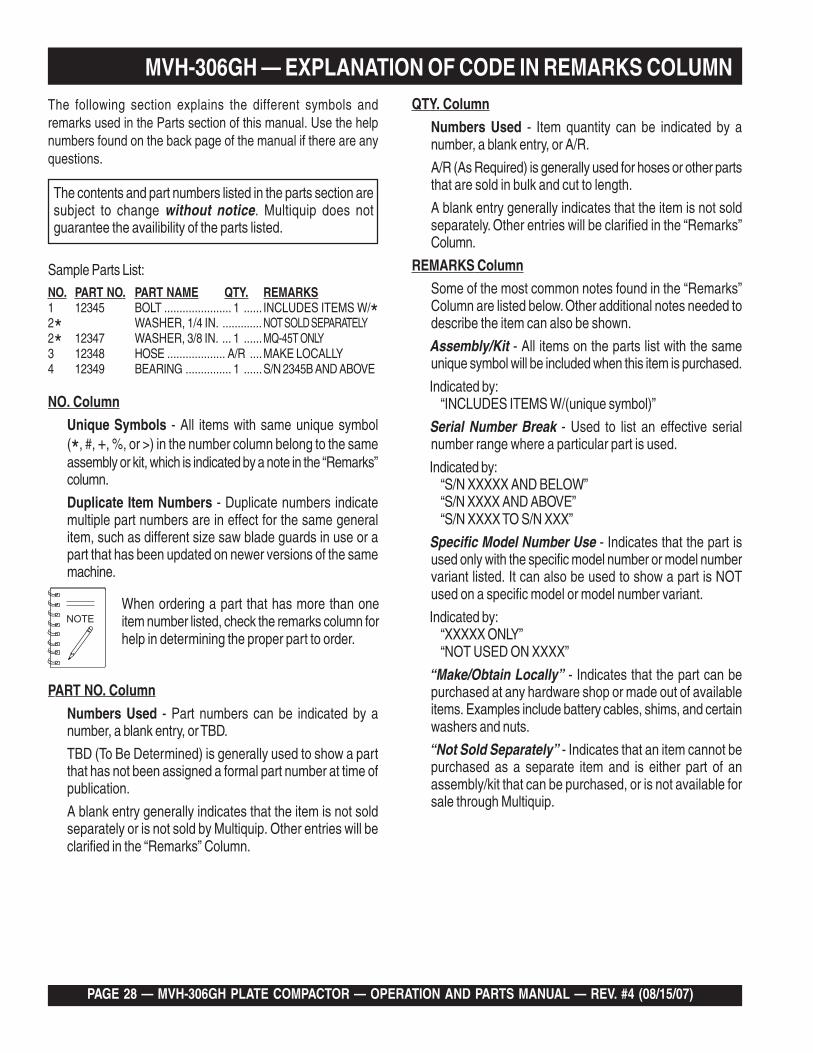
The contents and part numbers listed in the parts section aresubject to change without notice. Multiquip does notguarantee the availibility of the parts listed.
When ordering a part that has more than oneitem number listed, check the remarks column forhelp in determining the proper part to order.
The following section explains the different symbols andremarks used in the Parts section of this manual. Use the helpnumbers found on the back page of the manual if there are anyquestions.
NO. Column
Unique Symbols - All items with same unique symbol(*, #, +, %, or >) in the number column belong to the sameassembly or kit, which is indicated by a note in the “Remarks”column.
Duplicate Item Numbers - Duplicate numbers indicatemultiple part numbers are in effect for the same generalitem, such as different size saw blade guards in use or apart that has been updated on newer versions of the samemachine.
Sample Parts List:NO. PART NO. PART NAME QTY. REMARKS1 12345 BOLT ...................... 1 ...... INCLUDES ITEMS W/*2* WASHER, 1/4 IN. ............. NOT SOLD SEPARATELY2* 12347 WASHER, 3/8 IN. ... 1 ......MQ-45T ONLY3 12348 HOSE ................... A/R ....MAKE LOCALLY4 12349 BEARING ............... 1 ......S/N 2345B AND ABOVE
PART NO. Column
Numbers Used - Part numbers can be indicated by anumber, a blank entry, or TBD.
TBD (To Be Determined) is generally used to show a partthat has not been assigned a formal part number at time ofpublication.
A blank entry generally indicates that the item is not soldseparately or is not sold by Multiquip. Other entries will beclarified in the “Remarks” Column.
QTY. Column
Numbers Used - Item quantity can be indicated by anumber, a blank entry, or A/R.
A/R (As Required) is generally used for hoses or other partsthat are sold in bulk and cut to length.
A blank entry generally indicates that the item is not soldseparately. Other entries will be clarified in the “Remarks”Column.
REMARKS Column
Some of the most common notes found in the “Remarks”Column are listed below. Other additional notes needed todescribe the item can also be shown.
Assembly/Kit - All items on the parts list with the sameunique symbol will be included when this item is purchased.
Indicated by:“INCLUDES ITEMS W/(unique symbol)”
Serial Number Break - Used to list an effective serialnumber range where a particular part is used.
Indicated by:“S/N XXXXX AND BELOW”“S/N XXXX AND ABOVE”“S/N XXXX TO S/N XXX”
Specific Model Number Use - Indicates that the part isused only with the specific model number or model numbervariant listed. It can also be used to show a part is NOTused on a specific model or model number variant.
Indicated by:“XXXXX ONLY”“NOT USED ON XXXX”
“Make/Obtain Locally” - Indicates that the part can bepurchased at any hardware shop or made out of availableitems. Examples include battery cables, shims, and certainwashers and nuts.
“Not Sold Separately” - Indicates that an item cannot bepurchased as a separate item and is either part of anassembly/kit that can be purchased, or is not available forsale through Multiquip.

MVH-306GH PLATE COMPACTOR — OPERATION AND PARTS MANUAL — REV. #4 (08/15/07) — PAGE 29
MVH-306GH — SUGGESTED SPARE PARTS
MVH-306 W/HONDA GX270K1SMX2 ENGINE1 to 3 Units
Qty. ... P/N ...................... Description1 ....... 956100055 .......... THROTTLE WIRE2 ....... 070200363 .......... V-BELT3 ....... 9807955846 ......... SPARK PLUG3 ....... 17210ZE2822 ...... ELEMENT, AIR CLEANER (DUAL)1 ....... 17620Z0T814 ...... CAP, FUEL TANK1 ....... 28462ZE2W11 ..... ROPE, RECOIL

PAGE 30 — MVH-306GH PLATE COMPACTOR — OPERATION AND PARTS MANUAL — REV. #4 (08/15/07)
MVH-306GH — NAMEPLATE AND DECALS
NAMEPLATE AND DECALS

MVH-306GH PLATE COMPACTOR — OPERATION AND PARTS MANUAL — REV. #4 (08/15/07) — PAGE 31
MVH-306GH — NAMEPLATE AND DECALS
NAMEPLATE AND DECALS
NO. PART NO. PART NAME QTY. REMARKS1 920201950 DECAL: OIL SAE 10W-30........................... 1......... NPA-1953 920110370 DECAL: MODEL LOGO 14 920209620 DECAL: CAUTION ...................................... 1......... NPA-9625 920207480 DECAL: SHELL TELLUS OIL 46 ................ 1......... NPA-7486 920204580 DECAL: FULL THROTTLE .......................... 1......... NPA-4587 920203330 DECAL: EAR PROTECTION ...................... 1......... DCL3338 920211060 DECAL: CAUTION (TRAVEL LEVER) ........ 1......... NPA-11069 DECAL: SERIAL NO. .................................. 1 ......... CONTACT MQ PARTS DEPT.10 920201580 DECAL: MQ LOGO 111 920211010 DECAL: V-BELT HDPF-5370 ...................... 1......... NPA-537

PAGE 32 — MVH-306GH PLATE COMPACTOR — OPERATION AND PARTS MANUAL — REV. #4 (08/15/07)
MVH-306GH — VIBRATING PLATE ASSY.
VIBRATING PLATE ASSY.

MVH-306GH PLATE COMPACTOR — OPERATION AND PARTS MANUAL — REV. #4 (08/15/07) — PAGE 33
MVH-306GH — VIBRATING PLATE ASSY.
VIBRATING PLATE ASSY.
NO. PART NO. PART NAME QTY. REMARKS1 464117840 VIBRATING PLATE 12 953405840 DRAIN PLUG MI8 (H) 13 953402930 COPPER PACKING 19X30X1 14 953400270 PLUG 1/4X14 10L 15 953405260 PACKING 1/4 (CU) 16 939010260 SHOCK ABSORBER 110X60H 47 020316130 NUT M16 48 030216400 WASHER, LOCK M16 49 001221635 BOLT 16X35 T 410 001221830 BOLT 18X30 T 811 58407 WASHER, LOCK M18 812 030216400 WASHER, LOCK M16 415 939010010 SHOCK ABSORBER, STOPPER 45 416 020310080 NUT M10 417 031110160 WASHER, FLAT M10 418 030210250 WASHER, LOCK M10 419 464343730 COVER, VIBRATING PLATE 220 011008015 BOLT 8X15 T 821 030208200 WASHER, LOCK M8 831 52993 EXTENSION PLATE 232 012218050 BOLT 18X50 T 833 58407 WASHER, LOCK M18 8

PAGE 34 — MVH-306GH PLATE COMPACTOR — OPERATION AND PARTS MANUAL — REV. #4 (08/15/07)
MVH-306GH — BASE AND ENGINE ASSY.
BASE AND ENGINE ASSY.

MVH-306GH PLATE COMPACTOR — OPERATION AND PARTS MANUAL — REV. #4 (08/15/07) — PAGE 35
MVH-306GH — BASE AND ENGINE ASSY.
BASE & ENGINE ASSY.
NO. PART NO. PART NAME QTY. REMARKS1 464117850 BASE 12 912227003 ENGINE ASSY., GX270K1SMX2 (HONDA) 13 0105051045 BOLT 10X45 T 44 030210250 WASHER, LOCK M10 45 031110160 WASHER, FLAT M10 46 464216580 BELT COVER (IN) 17 001121025 BOLT 8X25 T 48 030210250 WASHER, LOCK M10 49 031110160 WASHER, FLAT M10 410 464343670 DUST-PROOF SPONGE (IN) 111 464457360 SPACER 112 456343340 CLUTCH ASSY./CHM03/W.FAN 113 951400110 KEY 7X7X35 114 952400690 WASHER 9X35X4.5 115 001220830 BOLT 8X30 T 116 030208200 WASHER, LOCK M8 117 464216640 DUST-PROOF COVER 118 092006010 FLAT HEAD SCREW 6X10 319 464343660 DUST-PROOF SPONGE (OUT) 120 464216590 BELT COVER (OUT) 121 001521050 SOCKET HEAD BOLT 10X50 T 426 464457430 SPACER, ENGINE 235 464117920 RUBBER COVER (GUARD FRAME) 136 456449950 PLATE, COVER 137 011208030 BOLT 8X30 T 138 030208200 WASHER, LOCK M8 339 031108160 WASHER, FLAT M8 340 022710809 NYLON NUT M8 3

PAGE 36 — MVH-306GH PLATE COMPACTOR — OPERATION AND PARTS MANUAL — REV. #4 (08/15/07)
MVH-306GH — BASE AND ENGINE ASSY. (CONTINUED)
BASE AND ENGINE ASSY. (CONTINUED)

MVH-306GH PLATE COMPACTOR — OPERATION AND PARTS MANUAL — REV. #4 (08/15/07) — PAGE 37
MVH-306GH — BASE AND ENGINE ASSY. (CONTINUED)
BASE AND ENGINE ASSY. (CONTINUED)
NO. PART NO. PART NAME QTY. REMARKS41 459010060 UNION TIP, DRAIN 142 459010070 DRAIN HOSE 143 459010090 HOSE BAND 244 459010080 GASKET(OIL DRAIN) 245 0401140030 PLUG 146 464457380 DRAIN JOINT 147 014208020 BOLT 8X20 T 148 030208200 WASHER, LOCK M8 151 464117900 GUARD HOOK 152 012214030 BOLT 14X30 T 453 030214350 WASHER, LOCK M14 459 90131ZE3790 DRAIN JOINT 160 9410912000 WASHER, DRAIN PLUG M12 161 070200363 V-BELT 162 0830000010 COIL SPRING 163 151010680 CLAMP CP. 164 58151 WASHER, FLAT M5 170 959407260 CLIP D6 (FOR M10) 171 001221015 BOLT 10X15 T 172 030210250 WASHER, LOCK M10 1

PAGE 38 — MVH-306GH PLATE COMPACTOR — OPERATION AND PARTS MANUAL — REV. #4 (08/15/07)
MVH-306GH — VIBRATOR ASSY.
VIBRATOR ASSY.

MVH-306GH PLATE COMPACTOR — OPERATION AND PARTS MANUAL — REV. #4 (08/15/07) — PAGE 39
MVH-306GH — VIBRATOR ASSY.
VIBRATOR ASSY.
NO. PART NO. PART NAME QTY. REMARKS1# 464117880 VIBRATING CASE 12 001221470 BOLT 14X150 T 63 001221450 BOLT 14X50 T 44 030214350 WASHER, LOCK M14 105# 047920120 ROLLER BEARING NJ310EMC4 46# 457212410 ROTARY SHAFT, DRIVE 18# 951405370 KEY 15X10X39 RR 19# 456327150 GEAR, DRIVE 110# 080200550 STOP RING S-55 211# 060105030 OIL SEAL SB-50729 112# 951404970 KEY 12X8X30 R 113# 464343700 ECCENTRIC ROTATOR 414# 009120301 SOCKET HEAD BOLT 16X40 T 215# 456337670 ROTARY SHAFT, DRIVEN 116# 009120302 SOCKET HEAD BOLT 16X30 T 217# 456337380 PISTON ROD 118# 456010010 KNOCK PIN 10X70 119# 464343720 GEAR (DRIVEN) 120# 040006911 BEARING 6911 221# 953010030 SEAL CAP/SC72-8N 125# 042506000 BEARING 6000ZZSG 226# 080200100 STOP RING S-10 127# 455435051 PISTON, 22.4D 128# 455010070 PACKING USH-22.4X30X5 129# 080100260 STOP RING R-26 130# 456327130 BEARING COVER 131# 456210636 CYLINDER (L)/(AC) 133# 050101050 O-RING G-105 234# 0012221025 BOLT 10X25 T 835# 030210250 WASHER, LOCK M10 836# 011008015 BOLT 8X12 T 137# 953404600 COPPER PACKING 8X16X2 138# 455010020 ELBOW 45 DEG. 15-0404 139# 031110160 WASHER, FLAT M10 443# 952405470 SHIM 90X110X0.5 246# 464343710 PULLEY 147# 464457370 WASHER 148# 012212030 BOLT 12X30 T 149# 030212300 WASHER, LOCK M12 151 464216600 BELT COVER (LOWER) 152 001520852 SOCKET HEAD BOLT 8X60 T 553 464910020 VIBRATOR ASSY ................................................1 ............. INCLUDES ITEMS W/#

PAGE 40 — MVH-306GH PLATE COMPACTOR — OPERATION AND PARTS MANUAL — REV. #4 (08/15/07)
MVH-306GH — CONTROL HANDLE ASSY.
CONTROL HANDLE ASSY.

MVH-306GH PLATE COMPACTOR — OPERATION AND PARTS MANUAL — REV. #4 (08/15/07) — PAGE 41
MVH-306GH — CONTROL HANDLE ASSY.
CONTROL HANDLE ASSY.NO. PART NO. PART NAME QTY. REMARKS1 464343680 HANDLE BRACKET 12 456336420 HANDLE BRACKET (R) 13 012212035 BOLT 12X35 T 44 030212300 WASHER, LOCK M12 45 031112230 WASHER, FLAT M12 47 456336400 RUBBER COUPLING 28 456449940 SHOCK ABSORBER 29 456449930 RUBBER PLATE 210 001221681 BOLT 16X250 T 111 032124400 CONICAL SPRING WASHER M24 212 025306016 SPRING PIN 6X16 213 0401450160 WASHER, FLAT M16 214 020316130 NUT M16 115 020416100 NUT M16, H=10 118 455434950 SPINDLE 119 455010030 KNOB 120 939010060 SHOCK ABSORBER 121 020310080 NUT M10, H=6 122 020412070 NUT M12, H=7 123 022411635 WING NUT M16 125 954404230 CLAMP SA120-18 126 011206020 BOLT 6X20 T 127 030206150 WASHER, LOCK M6 128 952404470 WASHER, FLAT M6 129 020106050 NUT M6 134 501402870 HANDLE STOPPER 135 501402880 SPRING/HANDLE (1.4X18X44) 136 959403460 BALL GRIP 32D-M10 137 020310080 NUT M10, H=6 138 456449980 RUBBER PACKING 9D-20D-5T 139 953405260 PACKING 1/4 (CU) 140 031110160 WASHER, FLAT M10 143 464343690 HANDLE COVER 144 0105050616 BOLT 6X15 T 645 030206150 WASHER, LOCK M6 646 952404470 WASHER, FLAT M6 647 464457710 PACKING A, HANDLE COVER 148 464457720 PACKING B, HANDLE COVER 149 454010020 CLAMP TC-100 1

PAGE 42 — MVH-306GH PLATE COMPACTOR — OPERATION AND PARTS MANUAL — REV. #4 (08/15/07)
MVH-306GH — CONTROL HANDLE ASSY. (CONTINUED)
CONTROL HANDLE ASSY.

MVH-306GH PLATE COMPACTOR — OPERATION AND PARTS MANUAL — REV. #4 (08/15/07) — PAGE 43
MVH-306GH — CONTROL HANDLE ASSY. (CONTINUED)
CONTROL HANDLE ASSY.
NO. PART NO. PART NAME QTY. REMARKS61 464117890 HANDLE 164 464216630 TRAVEL LEVER 165 464457400 HANDLE BOSS 166 012010030 BOLT 10X30 T 267 030210250 WASHER, LOCK M10 268 464216620 GRIP 169 030210250 WASHER, LOCK M10 270 031110160 WASHER, FLAT M10 271 020310080 NUT M10 272 011208025 BOLT 8X25 T 273 030208200 WASHER, LOCK 280 464457340 THROTTLE LEVER 181 959403840 BAR GRIP I.D. 12 MM 182 464457420 COVER, THROTTLE 183 464457350 ARM, THROTTLE 184 001520820 SOCKET HEAD BOLT 8X20 T 185 031116260 WASHER, FLAT 186 458460660 WASHER 16.4-35-0.6 287 033910080 CONICAL SW 16.3 X 31.5 X 1.2 388 464457440 STEEL BALL D6 (SUJ) 189 464010010 DRY BUSHING/ LBF-1620 190 001220625 BOLT 6X25 T 291 020306050 NUT M6 293 464010020 ROD END M5 194 001520520 SOCKET HEAD BOLT 5X20 T 195 031105080 WASHER, FLAT M5 196 20305040 NUT M5 199 954002270 OIL HOSE W/SPRING 1/4 X 920 1101 956100055 THROTTLE WIRE 1103 454010020 CLAMP TC-100 1104 959021815 SPRIAL TUBE 6D-330L 1104 959021810 SPRIAL TUBE KEP6/ L=500 1

PAGE 44 — MVH-306GH PLATE COMPACTOR — OPERATION AND PARTS MANUAL — REV. #4 (08/15/07)
MVH-306GH — HAND PUMP ASSY.HAND PUMP ASSY.

MVH-306GH PLATE COMPACTOR — OPERATION AND PARTS MANUAL — REV. #4 (08/15/07) — PAGE 45
HAND PUMP ASSY.
NO. PART NO. PART NAME QTY. REMARKSB* 4649-10040 ACCUMLATOR 1C* 464910080 O-RING DUST,SEAL,SET ......................1 ............. INCLUDES ITEMS W/#2* 464010040 CONTROL SHAFT 13* 464010050 BUSH 24* 464010060 CAM 19* 464010070 STOPPER 210* 099205005 SOCKET HEAD SCREW 5X5 T 211* 464010080 PLUG 112* 464010090 PIN,STOPPER 213* 464010100 PLUG 214* 458010080 BREATHER 115* 001520620 SOCKET HEAD BOLT 6X20 T 116#* 050200200 O-RING P-20 217#* 050200220 O-RING P-22 218#* 050300380 O-RING S-38 119#* 050200180 O-RING P-18 122* 464010110 ACCUMULATOR CASE ..........................1 ............. S/N N2418 AND BELOW22* 464010111 ACCUMULATOR CASE ..........................1 ............. S/N N2419 AND ABOVE26#* 050300400 O-RING S-40 127#* 050200150 O-RING P-15 128#* 050100400 O-RING G-40 150* 464010120 SPRING PLUG 151* 458451630 BREATHER CAP 152#* 069904010 DUST SEAL SER-40 ..............................1 ............. S/N N2419 AND ABOVE53#* 069901010 DUST SEAL SER-15 ..............................1 ............. S/N N2419 AND ABOVE81* 984010030 SPRG.COMPRESSION TOOL 182* 984010040 DISASSEMBLING TOOL A 183* 984010050 DISASSEMBLING TOOL B 184 464216721 HAND PUMP ASSY ...............................1 ............. INCLUDES ITEMS W/*
MVH-306GH — HAND PUMP ASSY.

PAGE 46 — MVH-306GH PLATE COMPACTOR — OPERATION AND PARTS MANUAL — REV. #4 (08/15/07)
GX270K1-SMX2 ENGINE — AIR CLEANER ASSY.
AIR CLEANER ASSY.

MVH-306GH PLATE COMPACTOR — OPERATION AND PARTS MANUAL — REV. #4 (08/15/07) — PAGE 47
GX270K1-SMX2 ENGINE — AIR CLEANER ASSY.AIR CLEANER ASSY.
NO. PART NO. PART NAME QTY. REMARKS1 16271ZE2010 PACKING, ELBOW 12 17210ZE2822 ELEMENT,AIR CLEANER(DUAL) .............. 1 ...................... INCLUDES ITEM W/*3* 17218ZE2821 FILTER, OUTER 15 17231ZH9820 COVER, AIR CLEANER 16* 17232891000 GROMET,AIR CLEANER 17+ 17238ZE2310 COLLAR,AIR CLEANER 28+ 17239ZE1000 COLLAR(B),AIR CLEANER 19 17410ZE2020 ELBOW COMP.,AIR CLEANER ................ 1 ...................... INCLUDES ITEM W/+12 90325044000 NUT 113 90009ZE2003 BOLT-WASHER 6X22 114 9405006000 FLANGE NUT 6MM 215 17235ZE2820 NOSE, SILENCER 1

PAGE 48 — MVH-306GH PLATE COMPACTOR — OPERATION AND PARTS MANUAL — REV. #4 (08/15/07)
GX270K1-SMX2 ENGINE — CAMSHAFT ASSY.
CAMSHAFT ASSY.

MVH-306GH PLATE COMPACTOR — OPERATION AND PARTS MANUAL — REV. #4 (08/15/07) — PAGE 49
GX270K1-SMX2 ENGINE — CAMSHAFT ASSY.
CAMSHAFT ASSY.
NO. PART NO. PART NAME QTY. REMARKS1 14100ZE3020 CAMSHAFT ASSY .................................... 1 ...................... INCLUDES ITEM W/*2 14410ZE2013 ROD,PUSH 23 14431ZE2010 ARM,VALVE ROCKER 24 14441ZE2000 LIFTER,VALVE 25 14451ZE1013 PIBOT,ROCKER ARM 26* 14568ZE1000 SPRING,WEIGHT RETURN 17 14711ZE2000 VALVE, IN. 18 14721ZE2000 VALVE, EX. 19 14751ZE2003 SPRING,VALVE 210 14771ZE2000 RETAINER,IN.VALVE SPRING 111 14773ZE2000 RETAINER,EX.VALVE SPRING 112 14781ZE2000 ROTATOR,VALVE 113 14791ZE2010 PLATE,PUSH ROD GUIDE 114 90012ZE0010 PIBOT BOLT 8MM 215 90206ZE1000 NUT,PIBOT ADJUSTING 216 12209ZE8003 SEAL, VALVE STEM 1

PAGE 50 — MVH-306GH PLATE COMPACTOR — OPERATION AND PARTS MANUAL — REV. #4 (08/15/07)
GX270K1-SMX2 ENGINE — CARBURETOR ASSY.
CARBURETOR ASSY.

MVH-306GH PLATE COMPACTOR — OPERATION AND PARTS MANUAL — REV. #4 (08/15/07) — PAGE 51
GX270K1-SMX2 ENGINE — CARBURETOR ASSY.
CARBURETOR ASSY.
NO. PART NO. PART NAME QTY. REMARKS1*% 16010ZE2812 GASKET SET 12* 16011ZA0931 VALVE SET,FLOAT 13* 16013ZA0931 FLOAT SET 15* 16015ZE8005 CHAMBER SET,FLOAT ............................. 1 ...................... INCLUDES ITEM W/%8* 16028ZE0005 SCREW SET 19* 16044ZE2005 CHOKE SET 110 16100ZH9W21 CARBURETOR ASSY. (BE75B) ................ 1 ...................... INCLUDES ITEM W/*11* 16124ZE0005 SCREW, THROTTLE STOP 113* 16166ZH9W20 NOZZLE, MAINE 114* 16173001004 PACKING,CUP 115 16211ZE2000 INSULATOR, CARBURETOR 116 16220ZA0702 SPACER COMP.,CARBURETOR 117 16221ZA0800 PACKING, CARBURETOR 118 16223ZA0800 PACKING, INSULATOR 119 16610ZE1000 CHOKE LEVER COMP. ............................. 1 ...................... INCLUDES ITEM W/+20 16953ZE1812 LEVER,COCK 121* 16954ZE1812 PLATE,LEVER SETTING 123* 16956ZE1811 SPRING,COCK LEVER 124* 16957ZE1812 PACKING,FUEL COCK 125* 16967ZE0811 CUP,FUEL STRAINER 126* 93500030061H SCREW 3X6 227+ 9430520122 SPRING PIN 2X12 128* 99101ZH80800 JET, MAIN, #80 129* 99204ZE20400 JET SET,PILOT, #40 130* 16016ZH7W01 SCREW SET 131*% 16024ZE1811 DRAIN SCREW SET 132* 16172ZE3W10 COLLAR SET 1

PAGE 52 — MVH-306GH PLATE COMPACTOR — OPERATION AND PARTS MANUAL — REV. #4 (08/15/07)
GX270K1-SMX2 ENGINE — CONTROL ASSY.
CONTROL ASSY.

MVH-306GH PLATE COMPACTOR — OPERATION AND PARTS MANUAL — REV. #4 (08/15/07) — PAGE 53
GX270K1-SMX2 ENGINE — CONTROL ASSY.
CONTROL ASSY.
NO. PART NO. PART NAME QTY. REMARKS1 16551ZE2000 ARM, GOVERNOR 12 16555ZE2000 ROD, GOVERNOR 13 16561ZE2000 SPRING, GOVERNOR 14 16562ZE2000 SPRING, THROTTLE RETURN 16 16570ZE2W10 CONTROL ASSY.(REMOTE) ..................... 1 ...................... INCLUDES ITEM W/*10* 16571ZE2W00 LEVER, CONTROL 111* 16574ZE1000 LEVER SPRING 112* 16575ZE2W00 WASHER,CONTROL LEVER 113* 16576891000 HOLDER,CABLE 115* 16578ZE1000 SPACER,CONTROL LEVER 116* 16581ZE2W00 BASE COMP.,CONTROL 117* 16584883300 ADJUSTING SPRING 119* 16592883310 SPRING,CABLE RETURN 120* 16594883010 HOLDER, WIRE 124 90013883000 FLANGE BOLT 6X12 225 90015ZE5010 BOLT, GOVERNOR ARM 127* 90114SA0000 LOCK NUT 6MM 128* 90605230000 CIR CLIP 130* 93500040060H SCREW 4X6 132* 93500050280A SCREW, PAN 5X28 133* 93500050160A SCREW 5X16 135 9405006000 FLANGE NUT 6MM 1

PAGE 54 — MVH-306GH PLATE COMPACTOR — OPERATION AND PARTS MANUAL — REV. #4 (08/15/07)
GX270K1-SMX2 ENGINE — CRANKCASE COVER ASSY.CRANKCASE COVER ASSY.

MVH-306GH PLATE COMPACTOR — OPERATION AND PARTS MANUAL — REV. #4 (08/15/07) — PAGE 55
GX270K1-SMX2 ENGINE — CRANKCASE COVER ASSY.
CRANKCASE COVER ASSY.
NO. PART NO. PART NAME QTY. REMARKS2 11300ZH9S50 COVER ASSY., CRANKCASE .................. 1 ...................... INCULDES ITEM W/*3 11381ZE2801 PACKINNG,CASE COVER 14 15600735003 CAP ASSY.,OIL FILLER ........................... 1 ...................... INCLUDES ITEM W/%6 15600ZG4003 OIL PLUG .................................................. 1 ...................... INCLUDES ITEM W/%8% 15625ZE1003 PACKING, OIL FILLER CAP 29* 16510ZE2000 GOVERNOR ASSY. ................................... 1 ...................... INCLUDES ITEM W/+10*+ 16511ZE2000 WEIGHT, GOVERNOR 211*+ 16512ZE2000 HOLDER, GOVERNOR WEIGHT 112*+ 16513ZE2000 PIN,GOVERNOR WEIGHT 213* 16531Z0A000 SLIDER, GOVERNOR 115* 90602ZE1000 CLIP, GOVERNOR HOLDER 116 90701HC4000 PIN,DOWEL 8X12 217* 91201890003 OIL SEAL, 30X46X8 118* 9410106800 PLAIN WASHER 6MM 119 957010803500 FLANGE BOLT 8X35 720* 961006206000 BALL BEARING 6206 1

PAGE 56 — MVH-306GH PLATE COMPACTOR — OPERATION AND PARTS MANUAL — REV. #4 (08/15/07)
GX270K1-SMX2 ENGINE — CRANKSHAFT ASSY.CRANKSHAFT ASSY.

MVH-306GH PLATE COMPACTOR — OPERATION AND PARTS MANUAL — REV. #4 (08/15/07) — PAGE 57
GX270K1-SMX2 ENGINE — CRANKSHAFT ASSY.
CRANKSHAFT ASSY.
NO. PART NO. PART NAME QTY. REMARKS1 13310ZH9000 CRANK SHAFT COMP. ............................. 1 ...................... INCULDES ITEM W/*9 92101080250A BOLT 8X25 111 90534706010 WASHER,LOCK 8MM 112 951400110 KEY 7X7X35 113* 91001ZH9003 BEARING, BALL (6206 SH) 1
PAGE 58 — MVH-306GH PLATE COMPACTOR — OPERATION AND PARTS MANUAL — REV. #4 (08/15/07)
GX270K1-SMX2 ENGINE — CYLINDER BARREL ASSY.
CYLINDER BARREL ASSY.

MVH-306GH PLATE COMPACTOR — OPERATION AND PARTS MANUAL — REV. #4 (08/15/07) — PAGE 59
GX270K1-SMX2 ENGINE — CYLINDER BARREL ASSY.
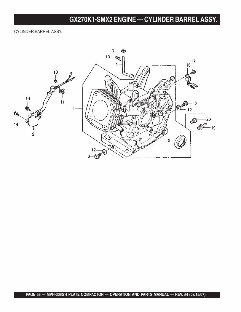
CYLINDER BARREL ASSY.
NO. PART NO. PART NAME QTY. REMARKS1 12000ZH9406 BARREL ASSY.,CYLINDER ...................... 1 ...................... INCULDES ITEM W/*2 15510ZE2043 SWITCH ASSY,OIL LEVEL 13 16541ZE2010 SHAFT,GOVERNOR ARM 16 90131883000 BOLT,DRAIN PLUG 27 90446KE1000 WASHER 8.2X17X0.8 19* 91201890003 OIL SEAL, 30X46X8 110 91353671004 O-RING 14MM 111 9405010000 FLANGE NUT M10 112 9410912000 WASHER,DRAIN PLUG M12 213 9425110000 PIN,LOCK 10MM 114 957010601200 FLANGE BOLT 6X12 216 34150ZH7003 ALERT UNIT, OIL 117 90013883000 FLANGE BOLT 6X12 119 90131ZE3790 DRAIN JOINT 120 9280012000 BOLT, DRAIN PLUG 12MM 1

PAGE 60 — MVH-306GH PLATE COMPACTOR — OPERATION AND PARTS MANUAL — REV. #4 (08/15/07)
GX270K1-SMX2 ENGINE — CYLINDER HEAD ASSY.CYLINDER HEAD ASSY.

MVH-306GH PLATE COMPACTOR — OPERATION AND PARTS MANUAL — REV. #4 (08/15/07) — PAGE 61
GX270K1-SMX2 ENGINE — CYLINDER HEAD ASSY.CYLINDER HEAD ASSY.
NO. PART NO. PART NAME QTY. REMARKS1 12200ZH9000 HEAD COMP.,CYLINDER ......................... 1 ...................... INCULDES ITEM W/*2* 12204ZE2306 GUIDE,IN.VALVE(OVERSIZE) 13* 12205ZE2305 GUIDE,EX.VALVE(OVERSIZE) 14* 12216ZE2300 CLIP,VALVE GUIDE 15 12251ZH9000 GASKET, CYLINDER HEAD 16 12310ZE2020 COVER COMP.,HEAD 17 950051110030 TUBE,11X100 18 12391ZE2020 PACKING,HEAD COVER 19 14775ZE2010 SEAT,VALVE SPRING 111 90014ZE2000 BOLT,HEAD COVER 112 90042ZE2000 BOLT,STUD 8X123 213 92900080320E BOLT,STUD 8X32 214 90441ZE2010 WASHER COMP.,HEAD COVER 115 9430112200 PIN,DOWEL 12X20 216 957251008000 BOLT,FLANGE 10X80 417 9807955846 PLUG, SPARK (BPR5ES) 1

PAGE 62 — MVH-306GH PLATE COMPACTOR — OPERATION AND PARTS MANUAL — REV. #4 (08/15/07)
GX270K1-SMX2 ENGINE — FAN COVER ASSY.
FAN COVER ASSY.

MVH-306GH PLATE COMPACTOR — OPERATION AND PARTS MANUAL — REV. #4 (08/15/07) — PAGE 63
GX270K1-SMX2 ENGINE — FAN COVER ASSY.FAN COVER ASSY.
NO. PART NO. PART NAME QTY. REMARKS3 16731ZE2003 CLIP,TUBE 15 19610ZE2010ZC COVER COMP.,FAN /BLACK 17 19631ZE2D00 SHROUD 111 36100ZH7003 STOP SWITCH ASSY. 117 90013883000 FLANGE BOLT 6X12 518 90013883000 FLANGE BOLT 6X12 122 90684ZA0601 CLIP, HARNESS 1

PAGE 64 — MVH-306GH PLATE COMPACTOR — OPERATION AND PARTS MANUAL — REV. #4 (08/15/07)
GX270K1-SMX2 ENGINE — FLYWHEEL ASSY.FLYWHEEL ASSY.

MVH-306GH PLATE COMPACTOR — OPERATION AND PARTS MANUAL — REV. #4 (08/15/07) — PAGE 65
GX270K1-SMX2 ENGINE — FLYWHEEL ASSY.FLYWHEEL ASSY.
NO. PART NO. PART NAME QTY. REMARKS1 19511ZE2000 FAN, COOLING 14 28451ZE2W01 PULLEY, STARTER 15 31100ZE2010 FLYWHEEL COMP. 18 90201ZE3V00 NUT,SPECIAL 16MM 19 90741ZE2000 KEY,SPECIAL WOODRUFF25X18 1

PAGE 66 — MVH-306GH PLATE COMPACTOR — OPERATION AND PARTS MANUAL — REV. #4 (08/15/07)
GX270K1-SMX2 ENGINE — FUEL TANK ASSY.
FUEL TANK ASSY.

MVH-306GH PLATE COMPACTOR — OPERATION AND PARTS MANUAL — REV. #4 (08/15/07) — PAGE 67
GX270K1-SMX2 ENGINE — FUEL TANK ASSY.
FUEL TANK ASSY.
NO. PART NO. PART NAME QTY. REMARKS1 16854ZH8000 RUBBER,SUPPORT(107MM) 12 16955ZE1000 JOINT,FUEL TANK 15 17510ZE2020ZD TANK COMP., FUEL NH1 17 17620Z0T814 CAP COMP., FUEL FILLER ...................... 1 ...................... INCLUDES ITEM W/*9 17672ZE2W01 FUEL FILTER 112 91353671004 O-RING 14MM 114 9405008000 FLANGE NUT M8 215 950014522240 TUBE, FUEEL 4.5X222 116 9500202080 CLIP, TUBE 217 957010802500 FLANGE BOLT 8X25 222* 17631Z0T812 PAKING, FUEL FILLER CAP 1

PAGE 68 — MVH-306GH PLATE COMPACTOR — OPERATION AND PARTS MANUAL — REV. #4 (08/15/07)
GX270K1-SMX2 ENGINE — IGNITION COIL ASSY.
IGNITION COIL ASSY.

MVH-306GH PLATE COMPACTOR — OPERATION AND PARTS MANUAL — REV. #4 (08/15/07) — PAGE 69
GX270K1-SMX2 ENGINE — IGNITION COIL ASSY.
IGNITION COIL ASSY.
NO. PART NO. PART NAME QTY. REMARKS1 30500-ZF6-W02 COIL AY,IGNITION/GX390 14 30700-ZE1-013 CAP ASSY. 18 31512-ZE2-000 GROMMET,CORD 110 36101-ZE1-010 CORD,STOP SWITCH 370MM 113 90015-883-000 FLANGE BOLT 6X28 1

PAGE 70 — MVH-306GH PLATE COMPACTOR — OPERATION AND PARTS MANUAL — REV. #4 (08/15/07)
GX270K1-SMX2 ENGINE — MUFFLER ASSY.
MUFFLER ASSY.

MVH-306GH PLATE COMPACTOR — OPERATION AND PARTS MANUAL — REV. #4 (08/15/07) — PAGE 71
GX270K1-SMX2 ENGINE — MUFFLER ASSY.
MUFFLER ASSY.
NO. PART NO. PART NAME QTY. REMARKS2 18310ZE2W00 MUFFLER COMP. 13 18320ZE2W01 PROTECTOR COMP.,MUFFLER 14 18323ZE2W00 PROTECTOR, EXHAUST PIPE 15 18330ZE2W00 PIPE,EXHAUST 17 18333ZE3800 GASKET 18 18355ZE2010 ARRESTER, SPARK 19 18381ZE2W10 GASKET,MUFFLER(ARRESTER) 118 90013883000 FLANGE BOLT 6X12 119 90050ZE1000 TAPPING SCREW 5X8 626 9405008000 FLANGE NUT M8 329 90050ZE1000 TAPPING SCREW 5X8 1
PAGE 72 — MVH-306GH PLATE COMPACTOR — OPERATION AND PARTS MANUAL — REV. #4 (08/15/07)
GX270K1-SMX2 ENGINE — PISTON ASSY.
PISTON ASSY.

MVH-306GH PLATE COMPACTOR — OPERATION AND PARTS MANUAL — REV. #4 (08/15/07) — PAGE 73
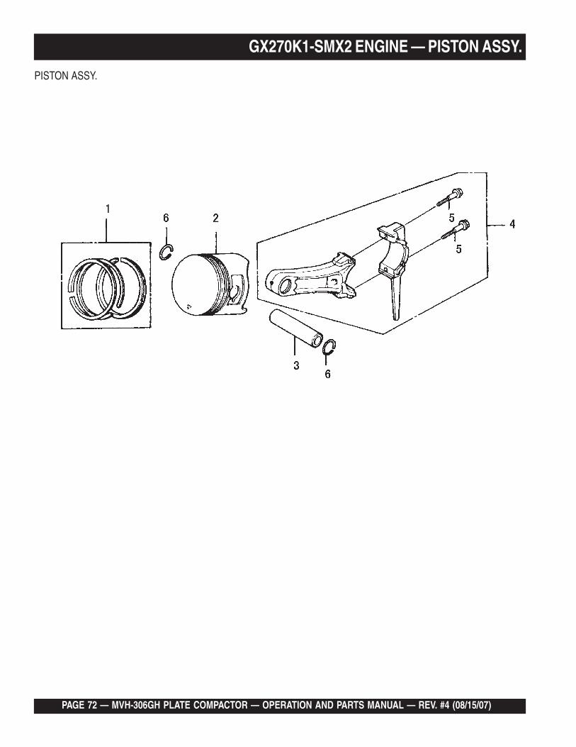
GX270K1-SMX2 ENGINE — PISTON ASSY.PISTON ASSY.
NO. PART NO. PART NAME QTY. REMARKS1 13010ZE8601 RING SET, PISTON (STD) 12 13101ZH9000 PISTON (STD) 13 13111ZE2000 PIN ,PISTON 14 13200E2010 ROD ASSY., CONNECTING (STD) ........... 1 ...................... INCLUDES ITEM W/*5* 90001E8000 BOLT, CONNECTING ROD 26 90551E1000 CLIP, PISTON PIN 18MM 2

PAGE 74 — MVH-306GH PLATE COMPACTOR — OPERATION AND PARTS MANUAL — REV. #4 (08/15/07)
GX270K1-SMX2 ENGINE — RECOIL STARTER ASSY.
RECOIL STARTER ASSY.

MVH-306GH PLATE COMPACTOR — OPERATION AND PARTS MANUAL — REV. #4 (08/15/07) — PAGE 75
GX270K1-SMX2 ENGINE — RECOIL STARTER ASSY.
RECOIL STARTER ASSY.
NO. PART NO. PART NAME QTY. REMARKS1 28400ZE2W01ZB RECOIL STARTER AY/GX240,B ............... 1 ..................... INCLUDES ITEM W/*2* 28410ZE2W01ZB CASE COMP.,RECOIL STARTER 13* 28421ZE2W01 PULLEY,RECOIL STARTER 14* 28422ZE2W01 RATCHET,STARTER 25* 28441ZE2W01 SPRING,FRICTION 16* 28442ZE2W01 SPRING,STARTER RETURN 17* 28443ZE2W01 SPRING,RATCHET 28* 28444ZE2W01 RETAINER,SPRING 110* 28461ZE2W02 GRIP,STARTER 111* 28462ZE2W11 ROPE, RECOIL STARTER 113* 90004ZE2W01 SCREW,CENTER 114 90008ZE2003 BOLT,FLANGE 6X10 3

PAGE 76 — MVH-306GH PLATE COMPACTOR — OPERATION AND PARTS MANUAL — REV. #4 (08/15/07)
GX270K1-SMX2 ENGINE — LABELS ASSY.LABELS ASSY.

MVH-306GH PLATE COMPACTOR — OPERATION AND PARTS MANUAL — REV. #4 (08/15/07) — PAGE 77
LABELS ASSY.
NO. PART NO. PART NAME QTY. REMARKS3 87521ZH9030 EMBLEM 17 87522ZH9010 RABEL /GX120K1 110 87528ZE2810 MARK,CHOKE(ORANGE) 117 87532ZH8810 LABEL 1
GX270K1-SMX2 ENGINE — LABELS ASSY.

PAGE 78 — MVH-306GH PLATE COMPACTOR — OPERATION AND PARTS MANUAL — REV. #4 (08/15/07)
PAYMENT TERMS
Terms of payment for parts are net 30 days.
FREIGHT POLICY
All parts orders will be shipped collect orprepaid with the charges added to the invoice.All shipments are F.O.B. point of origin.Multiquip’s responsibility ceases when a signedmanifest has been obtained from the carrier,and any claim for shortage or damage must besettled between the consignee and the carrier.
MINIMUM ORDER
The minimum charge for orders from Multiquipis $15.00 net. Customers will be asked forinstructions regarding handling of orders notmeeting this requirement.
RETURNED GOODS POLICY
Return shipments will be accepted and creditwill be allowed, subject to the following provi-sions:
1. A Returned Material Authorization mustbe approved by Multiquip prior to ship-ment.
2. To obtain a Return Material Authorization,a list must be provided to Multiquip PartsSales that defines item numbers, quanti-ties, and descriptions of the items to bereturned.
a. The parts numbers and descriptionsmust match the current parts pricelist.
b. The list must be typed or computergenerated.
c. The list must state the reason(s) forthe return.
d. The list must reference the salesorder(s) or invoice(s) under which theitems were originally purchased.
e. The list must include the name andphone number of the person request-ing the RMA.
3. A copy of the Return Material Authoriza-tion must accompany the return shipment.
4. Freight is at the sender’s expense. Allparts must be returned freight prepaid toMultiquip’s designated receiving point.
5. Parts must be in new and resalable con-dition, in the original Multiquip package (ifany), and with Multiquip part numbersclearly marked.
6. The following items are not returnable:
a. Obsolete parts. (If an item is in theprice book and shows as being re-placed by another item, it is obsolete.)
b. Any parts with a limited shelf life(such as gaskets, seals, “O” rings,and other rubber parts) that were pur-chased more than six months prior tothe return date.
c. Any line item with an extended dealernet price of less than $5.00.
d. Special order items.
e. Electrical components.
f. Paint, chemicals, and lubricants.
g. Decals and paper products.
h. Items purchased in kits.
7. The sender will be notified of any materialreceived that is not acceptable.
8. Such material will be held for five workingdays from notification, pending instruc-tions. If a reply is not received within fivedays, the material will be returned to thesender at his expense.
9. Credit on returned parts will be issued atdealer net price at time of the originalpurchase, less a 15% restocking charge.
10. In cases where an item is accepted, forwhich the original purchase documentcan not be determined, the price will bebased on the list price that was effectivetwelve months prior to the RMA date.
11. Credit issued will be applied to futurepurchases only.
PRICING AND REBATES
Prices are subject to change without priornotice. Price changes are effective on a spe-cific date and all orders received on or after thatdate will be billed at the revised price. Rebatesfor price declines and added charges for priceincreases will not be made for stock on handat the time of any price change.
Multiquip reserves the right to quote and selldirect to Government agencies, and to OriginalEquipment Manufacturer accounts who useour products as integral parts of their ownproducts.
SPECIAL EXPEDITING SERVICE
A $35.00 surcharge will be added to the invoicefor special handling including bus shipments,insured parcel post or in cases where Multiquipmust personally deliver the parts to the carrier.
LIMITATIONS OF SELLER’S LIABILITY
Multiquip shall not be liable hereunder fordamages in excess of the purchase price of theitem with respect to which damages areclaimed, and in no event shall Multiquip beliable for loss of profit or good will or for anyother special, consequential or incidental dam-ages.
LIMITATION OF WARRANTIES
No warranties, express or implied, are madein connection with the sale of parts or tradeaccessories nor as to any engine not manufac-tured by Multiquip. Such warranties made inconnection with the sale of new, complete unitsare made exclusively by a statement of war-ranty packaged with such units, and Multiquipneither assumes nor authorizes any person toassume for it any other obligation or liabilitywhatever in connection with the sale of itsproducts. Apart from such written statement ofwarranty, there are no warranties, express,implied or statutory, which extend beyond thedescription of the products on the face hereof.
Effective: February 22, 2006
TERMS AND CONDITIONS OF SALE — PARTS

MVH-306GH PLATE COMPACTOR — OPERATION AND PARTS MANUAL — REV. #4 (08/15/07) — PAGE 79
NOTES

Your Local Dealer is:
HERE'S HOW TO GET HELPPLEASE HAVE THE MODEL AND SERIAL
NUMBER ON-HAND WHEN CALLING
© COPYRIGHT 2007, MULTIQUIP INC.
Multiquip Inc, the MQ logo and the Mikasa logo are registered trademarks of Multiquip Inc. and may not be used, reproduced, or altered without written permission. All othertrademarks are the property of their respective owners and used with permission.
This manual MUST accompany the equipment at all times. This manual is considered a permanent part of the equipment and should remain with the unit if resold.
The information and specifications included in this publication were in effect at the time of approval for printing. Illustrations, descriptions, references and technical datacontained in this manual are for guidance only and may not be considered as binding. Multiquip Inc. reserves the right to discontinue or change specifications, design orthe information published in this publication at any time without notice and without incurring any obligations.
UNITED STATESMultiquip Corporate Office MQ Parts Department18910 Wilmington Ave. Tel. (800) 421-1244 800-427-1244 Fax: 800-672-7877Carson, CA 90746 Fax (800) 537-3927 310-537-3700 Fax: 310-637-3284Contact: [email protected] Parts Warranty Department800-306-2926 Fax: 800-672-7877 800-421-1244, Ext. 279 Fax: 310-537-1173310-537-3700 Fax: 310-637-3284 310-537-3700, Ext. 279Service Department Technial Assistance800-421-1244 Fax: 310-537-4259 800-478-1244 Fax: 310-631-5032310-537-3700
MEXICO UNITED KINGDOMMQ Cipsa Multiquip (UK) Limited Head OfficeCarr. Fed. Mexico-Puebla KM 126.5 Tel: (52) 222-225-9900 Hanover Mill, Fitzroy Street, Tel: 0161 339 2223Momoxpan, Cholula, Puebla 72760 Mexico Fax: (52) 222-285-0420 Ashton-under-Lyne, Fax: 0161 339 3226Contact: [email protected] Lancashire OL7 0TL
Contact: [email protected]
CANADA BRAZILMultiquip Multiquip4110 Industriel Boul. Tel: (450) 625-2244 Av. Evandro Lins e Silva, 840 - grupo 505 Tel: 011-55-21-3433-9055Laval, Quebec, Canada H7L 6V3 Fax: (450) 625-8664 Barra de Tijuca - Rio de Janeiro Fax: 011-55-21-3433-9055Contact: [email protected] Contact: [email protected], [email protected]
manufactured for Multiquip Inc.by
MIKASA SANGYO CO., LTD. Tokyo, Japan
OPERATION AND PARTS MANUAL