Series H - Industrial Gearbox Installation & Maintenanceradicon/_docs/iandmhmetric eng.pdfSeries H -...
24
IH-1.00GB0112 Series H - Industrial Gearbox Installation & Maintenance
Transcript of Series H - Industrial Gearbox Installation & Maintenanceradicon/_docs/iandmhmetric eng.pdfSeries H -...

IH-1.00GB0112
Series H - Industrial GearboxInstallation & Maintenance
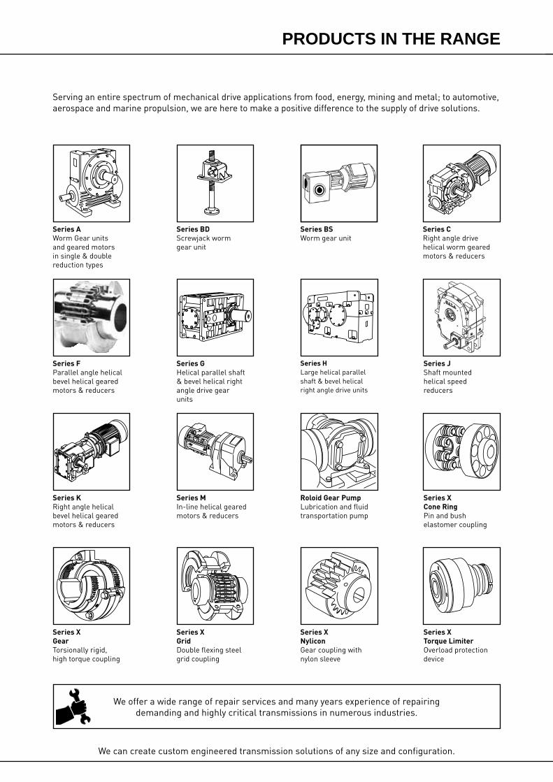
We can create custom engineered transmission solutions of any size and configuration.
Serving an entire spectrum of mechanical drive applications from food, energy, mining and metal; to automotive, aerospace and marine propulsion, we are here to make a positive difference to the supply of drive solutions.
We offer a wide range of repair services and many years experience of repairing demanding and highly critical transmissions in numerous industries.
Series XCone RingPin and bush elastomer coupling
Series XTorque LimiterOverload protection device
Series JShaft mounted helical speed reducers
Series CRight angle drive helical worm geared motors & reducers
Series BDScrewjack wormgear unit
Series GHelical parallel shaft & bevel helical right angle drive gear units
Series XGridDouble flexing steel grid coupling
Series MIn-line helical geared motors & reducers
Series HLarge helical parallel shaft & bevel helical right angle drive units
Roloid Gear PumpLubrication and fluid transportation pump
Series BSWorm gear unit
Series XNyliconGear coupling with nylon sleeve
Series AWorm Gear units and geared motors in single & double reduction types
Series XGearTorsionally rigid,high torque coupling
Series KRight angle helical bevel helical geared motors & reducers
Series FParallel angle helical bevel helical geared motors & reducers
PRODUCTS IN THE RANGE

SERIES HOrder No
Set No
Unit Type
Ratio
Input Speed
Noise Level @ 1m dB(A)*
������� ��������� �� ����
� ��������������������� �
� �������������������� �
!�����"�������#�����$�����%���$�� �
� �������������������� �
� ��$���������
�&� '�����$���������(���$�� )
�&� !�*��"�����($�����$��+(�#������ )
�& '���������������$�� )
�&� !����'�(���������$�� )
�&� �%����'�(���������$�,����+(������!�*��"�� -�.�/
�&) �#��������������������$�� /
�&- 0���1��2$�� /
) 3(1�������������'����������
)&� 3(1���������� �4
)&� �����������$#�������� �4
)& 3(1��������%��"�$�� �4
)&� 3(1�������5(�����6�� �4
)&� �##��7���3(1������$�� �4
)&) �##��7��� ���$�$�� �4
- �������"�� �4
������8
� ������"�����$�� ��
� 3(1�������5(�����6������##��7���3(1������$�� ���.���
�##��7���9�����"� ���$�$�� ��
� �%�������"�������� �)�.��-
� 9�����"$�� �:�.��/
) ��"%�����"����+(�$�������$��;�������(�$<���7�������0�($��"�9���$�� �4
- ���$�� ��
* The noise level will be obtained from the production test
������������
�
LUBRICATIONFill to correct Oil Level with oil of recommended grade
Drain and Flush at end of oil change periodSee approved Lubricants leaflet for futher details
SERIES 'H' GEAR UNITOrder No Type
Ratio
Oil Grade
kW Rating
Output RPM
Oil ChangePeriod
NO OF REDUCTIONS
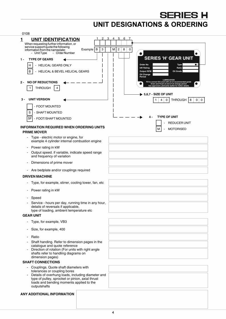
1 THROUGH 4
TYPE OF GEARS
H - HELICAL GEARS ONLY
B - HELICAL & BEVEL HELICAL GEARS
�������� ������������
B 3 M 2 8 0
1 2 3 4 5 6 7
1 -
2 -
UNIT VERSION
- FOOT MOUNTED
S - SHAFT MOUNTED
- FOOT/SHAFT MOUNTED
3 -
SF
INFORMATION REQUIRED WHEN ORDERING UNITSPRIME MOVER
- Type - electric motor or engine, forexample 4 cylinder internal combustion engine
- Power rating in kW
- Output speed. if variable, indicate speed rangeand frequency of variation
- Dimensions of prime mover
- Are bedplate and/or couplings required
DRIVEN MACHINE
- Type, for example, stirrer, cooling tower, fan, etc
- Power rating in kW
- Speed
- Service - hours per day, running time in any hour,details of reversals if applicable,type of loading, ambient temperature etc
GEAR UNIT
- Type, for example, VB3
- Size, for example, 400
- Ratio
- Shaft handing. Refer to dimension pages in thecatalogue and quote reference
- Direction of rotation (For units with right angleshafts refer to handling diagrams ondimension pages)
SHAFT CONNECTIONS
- Couplings. Quote shaft diameters withtolerances or coupling bores
- Details of overhung loads, including diameter andtype of pulley, sprocket or pinion, axial thrustloads and bending moments applied to theoutputshafts
ANY ADDITIONAL INFORMATION
TYPE OF UNIT
- REDUCER UNIT
M - MOTORISED
4 -
5,6,7 - SIZE OF UNIT
1 4 0 THROUGH 8 0 0
1 UNIT IDENTIFICATION������������ ����������������������������������������������������� �������������������������������
� ��������� � �������� ��Example
����

�
�� ��� ������� ���
�� ������� ������� ���
������� ������� ���
�� ������� ������� ���
����������� ������� ���
�� ������� ������� ���
������� ������� ���
��� ������� ���
�� ��� ������� ���
�� ������� ������� ���
������� ������� ���
�� ������� ������� ���
������� ������� ���
��� ������� ���
�� ������� ���
����� ������ ���
����� ������ ���
�� ������� ���
����� ������� ���
�� ������ ���
�� ������ ���
�� ������� ���
����� ������� ���
����� ������ ���
�������� ������� ���
����� ������� ���
�� ������� ���
����������� ������� ���
2 GENERAL INFORMATION������������� ������� ���������������������� �� ��������� ��������������������� ���������� ���������� ���� ����������� ��������������������������������������
������� ������� �������������������������� ���������������������������� �������������������� ���������������� ������ ���������������������� ���������� �����������������������������
������ !������������� ���������������� ������� �������������������������"�������� ����#����������� ���������������������������$������ ��������������� ���������� ������%������������������������������ ����
� ������������� ������ ��� ���� �������������������������������������������� ������&��� ��������������������� ����'�(������������)�*���� ������������+�,-��.������)�*���� �������������/�,-��.������������������������ � �����������'�(�����������01�*�����������������+�,-��.�����21�*�����������������/�,-���.�
3 '��� �* ����� ����� �� ������� ��������� ����.� ������������������������������ � ���� � ������ ����������������� ����� ������������� �
3 �������� ����������� ������������� ������ ����� ����4�������������������������������������������������������������� �����
3 '��� �����������������������������5-67--�8�������� ��������������
��#$�9$9��(:$�9$��':�
� � ��� ����� ����������������� ����������� ������������ ������������� �������������������������%����������������������������� ���������������� &������ �������������������� �����������;2��������� �� ������������� �������������������� �� ������������� ��������������� ���� ��������� ��������������������������������������
�������&��� �� ������������������ ���� ���������������������� ������������� ����������� �� ����������� ����������������3������ �������������7<������ �
=��� 7 �������������� ���������������������������������� ���������������������� ������������������� �������������������������� ������������������������$������ ��� ������������ ������ ���������������������������� �������������
< >������� ������������� ������������������� ���������������&������������� ������������������������������������������ ��������������������� ������������������������������������ ������ ���'���� � ������� ������������ ����������������������������� ���
�������
���
�������
�����������
�����������
������� ���
������� ���
������� ���
������� ���
������� ���
��� �� ��� ��� ���� �������
�������� ���������� ������� �� �������� �� ������������������ ������� �� �������� ��
�������� ���
�������� ���
�������� ���
�������� ���
�������� ���
�������� ���
�������� ���
�
5 INSTALLATION5.1 MOTORISED AND REDUCERS
WARNING: The customer shall be responsible for the proper use of articles supplied by thecompany, particularly the rotating shafts between their driving and driven members,and their guarding for safety, and the company shall not be responsible for anyinjury or damage sustained as a result of the improper use of the articles supplied.Attention is hereby drawn to the danger of using naked lights in proximity toopenings in gearboxes and gear units supplied by the company, and the companyshall not be liable for any claim for injury or damage arising from any action incontravention of this warning.
WARNING: All units and couplings are despatched without oil or grease, on installing the unit fillwith recommended lubricant to correct level.
NOTE: If lubricant is to be added later then it is important that the same oil is used as isalready in the unit.If an oil other than that in the unit is to be used the unit should be drained andflushed with the oil to be used and filled with the correct quantity.
5.2 FIXING TO CUSTOMER EQUIPMENT
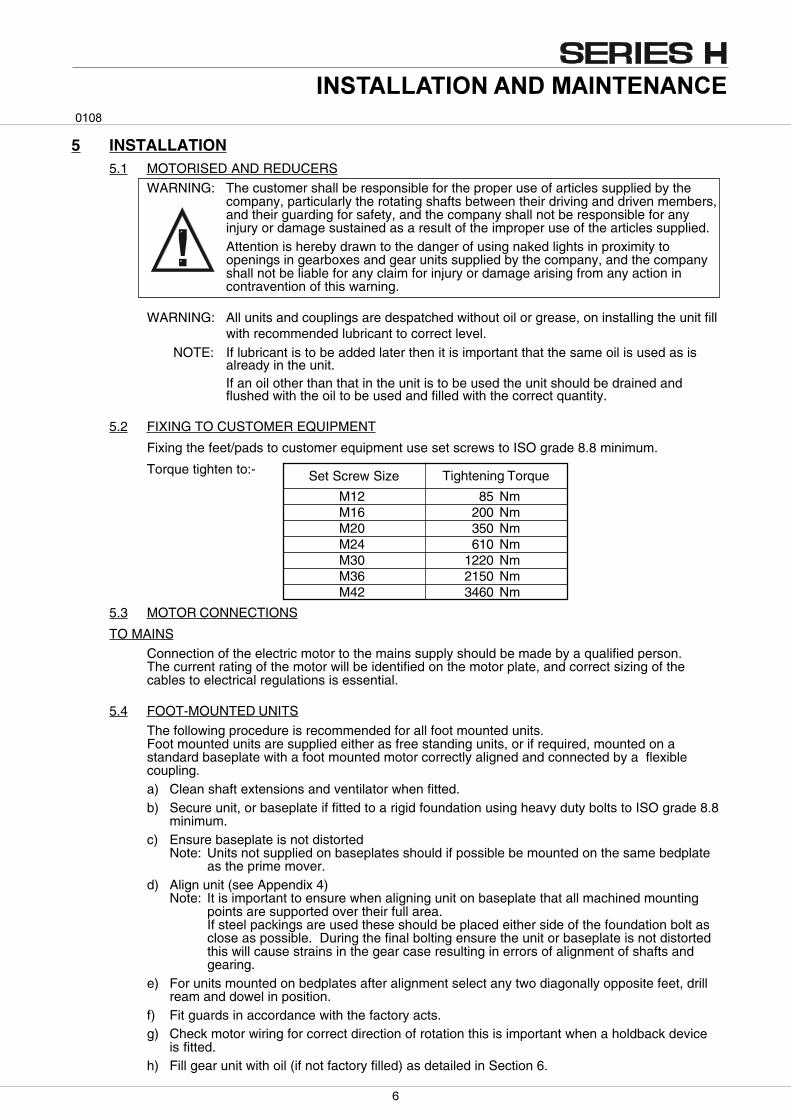
Fixing the feet/pads to customer equipment use set screws to ISO grade 8.8 minimum.
Torque tighten to:-
5.3 MOTOR CONNECTIONS
TO MAINS
Connection of the electric motor to the mains supply should be made by a qualified person.The current rating of the motor will be identified on the motor plate, and correct sizing of thecables to electrical regulations is essential.
5.4 FOOT-MOUNTED UNITS
The following procedure is recommended for all foot mounted units.Foot mounted units are supplied either as free standing units, or if required, mounted on astandard baseplate with a foot mounted motor correctly aligned and connected by a flexiblecoupling.a) Clean shaft extensions and ventilator when fitted.b) Secure unit, or baseplate if fitted to a rigid foundation using heavy duty bolts to ISO grade 8.8
minimum.c) Ensure baseplate is not distorted
Note: Units not supplied on baseplates should if possible be mounted on the same bedplateas the prime mover.
d) Align unit (see Appendix 4)Note: It is important to ensure when aligning unit on baseplate that all machined mounting
points are supported over their full area.If steel packings are used these should be placed either side of the foundation bolt asclose as possible. During the final bolting ensure the unit or baseplate is not distortedthis will cause strains in the gear case resulting in errors of alignment of shafts andgearing.
e) For units mounted on bedplates after alignment select any two diagonally opposite feet, drillream and dowel in position.
f) Fit guards in accordance with the factory acts.g) Check motor wiring for correct direction of rotation this is important when a holdback device
is fitted.h) Fill gear unit with oil (if not factory filled) as detailed in Section 6.
M12 85 NmM16 200 NmM20 350 NmM24 610 NmM30 1220 NmM36 2150 NmM42 3460 Nm
Set Screw Size Tightening Torque
��� �� ��� ��� ���� �������
!
�
5.5 SHAFT MOUNTED UNITS
The following procedure is recommended for all shaft and foot/shaft mounted units.
a) Clean shaft extensions, bore and ventilator when fitted.
b) Locate in position, ensuring it is as close as possible to the bearing on the driven machine.
c) Secure unit onto the shaft.
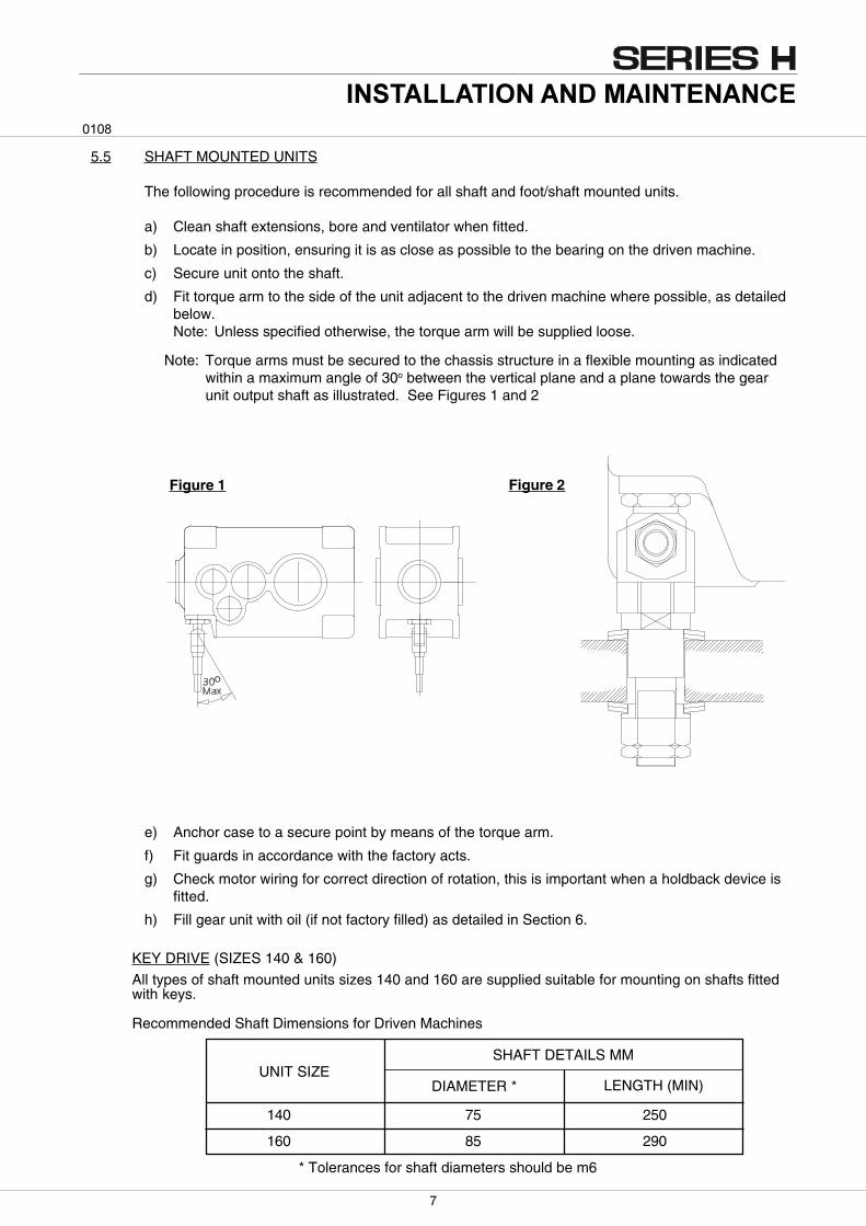
d) Fit torque arm to the side of the unit adjacent to the driven machine where possible, as detailedbelow.Note: Unless specified otherwise, the torque arm will be supplied loose.
140 75 250
160 85 290
UNIT SIZEDIAMETER * LENGTH (MIN)
SHAFT DETAILS MM
* Tolerances for shaft diameters should be m6
KEY DRIVE (SIZES 140 & 160)
All types of shaft mounted units sizes 140 and 160 are supplied suitable for mounting on shafts fittedwith keys.
Recommended Shaft Dimensions for Driven Machines
e) Anchor case to a secure point by means of the torque arm.
f) Fit guards in accordance with the factory acts.
g) Check motor wiring for correct direction of rotation, this is important when a holdback device isfitted.
h) Fill gear unit with oil (if not factory filled) as detailed in Section 6.
Figure 1 Figure 2
Note: Torque arms must be secured to the chassis structure in a flexible mounting as indicatedwithin a maximum angle of 30o between the vertical plane and a plane towards the gearunit output shaft as illustrated. See Figures 1 and 2
��� �� ��� ��� ���� �������
�
Screws
degreased
greased
Shaft
Hub
Inner ring
'O' ring
LockingcollarsLockingcollars
L3
L2
L1
øD
ød
ød
1
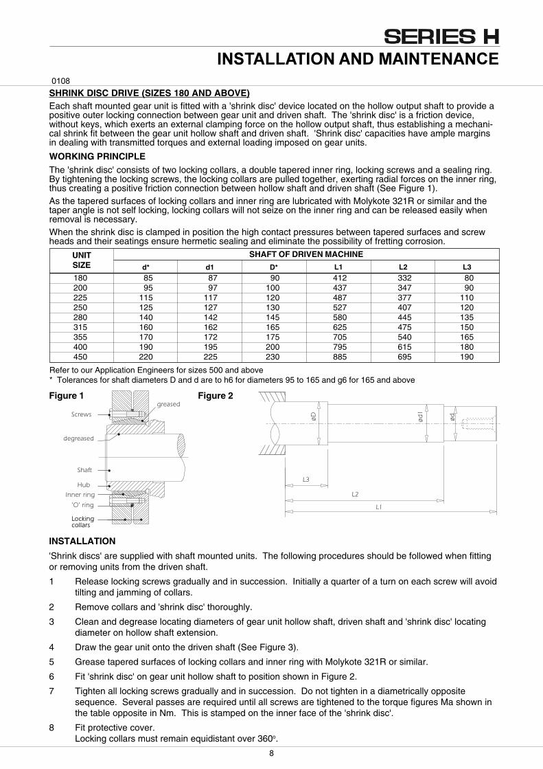
SHRINK DISC DRIVE (SIZES 180 AND ABOVE)Each shaft mounted gear unit is fitted with a 'shrink disc' device located on the hollow output shaft to provide apositive outer locking connection between gear unit and driven shaft. The 'shrink disc' is a friction device,without keys, which exerts an external clamping force on the hollow output shaft, thus establishing a mechani-cal shrink fit between the gear unit hollow shaft and driven shaft. 'Shrink disc' capacities have ample marginsin dealing with transmitted torques and external loading imposed on gear units.
WORKING PRINCIPLEThe 'shrink disc' consists of two locking collars, a double tapered inner ring, locking screws and a sealing ring.By tightening the locking screws, the locking collars are pulled together, exerting radial forces on the inner ring,thus creating a positive friction connection between hollow shaft and driven shaft (See Figure 1).As the tapered surfaces of locking collars and inner ring are lubricated with Molykote 321R or similar and thetaper angle is not self locking, locking collars will not seize on the inner ring and can be released easily whenremoval is necessary.When the shrink disc is clamped in position the high contact pressures between tapered surfaces and screwheads and their seatings ensure hermetic sealing and eliminate the possibility of fretting corrosion.
SHAFT OF DRIVEN MACHINE
d* D*
UNITSIZE d1 L1 L2 L3
180 85 87 90 412 332 80200 95 97 100 437 347 90225 115 117 120 487 377 110250 125 127 130 527 407 120280 140 142 145 580 445 135315 160 162 165 625 475 150355 170 172 175 705 540 165400 190 195 200 795 615 180450 220 225 230 885 695 190
Figure 1 Figure 2
INSTALLATION
'Shrink discs' are supplied with shaft mounted units. The following procedures should be followed when fittingor removing units from the driven shaft.
1 Release locking screws gradually and in succession. Initially a quarter of a turn on each screw will avoidtilting and jamming of collars.
2 Remove collars and 'shrink disc' thoroughly.
3 Clean and degrease locating diameters of gear unit hollow shaft, driven shaft and 'shrink disc' locatingdiameter on hollow shaft extension.
4 Draw the gear unit onto the driven shaft (See Figure 3).
5 Grease tapered surfaces of locking collars and inner ring with Molykote 321R or similar.
6 Fit 'shrink disc' on gear unit hollow shaft to position shown in Figure 2.
7 Tighten all locking screws gradually and in succession. Do not tighten in a diametrically oppositesequence. Several passes are required until all screws are tightened to the torque figures Ma shown inthe table opposite in Nm. This is stamped on the inner face of the 'shrink disc'.
8 Fit protective cover.Locking collars must remain equidistant over 360o.
��� �� ��� ��� ���� �������
Refer to our Application Engineers for sizes 500 and above* Tolerances for shaft diameters D and d are to h6 for diameters 95 to 165 and g6 for 165 and above
Shrink disc
Nut
JackingscrewJackingscrew
Jacking screw
Jacking plate
Protective discDriven shaft
Unit output sleeveJacking plate
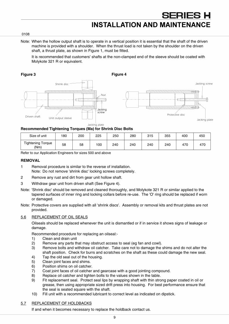
Note: When the hollow output shaft is to operate in a vertical position it is essential that the shaft of the drivenmachine is provided with a shoulder. When the thrust load is not taken by the shoulder on the drivenshaft, a thrust plate, as shown in Figure 1, must be fitted.
It is recommended that customers' shafts at the non-clamped end of the sleeve should be coated withMolykote 321 R or equivalent.
5.6 REPLACEMENT OF OIL SEALS
Oilseals should be replaced whenever the unit is dismantled or if in service it shows signs of leakage ordamage.
Recommended procedure for replacing an oilseal:-1) Clean and drain unit2) Remove any parts that may obstruct access to seal (eg fan and cowl).3) Remove bolts and withdraw oil catcher. Take care not to damage the shims and do not alter the
shaft position. Check for burrs and scratches on the shaft as these could damage the new seal.4) Tap the old seal out of the housing.5) Clean joint faces and shims.6) Position shims on oil catcher.7) Coat joint faces of oil catcher and gearcase with a good jointing compound.8) Replace oil catcher and tighten bolts to the values shown in the table.9) Fit replacement seal. Protect seal lips by wrapping shaft with thin strong paper coated in oil or
grease, then using appropriate sized drift press into housing. For best performance ensure thatthe seal is seated square with the shaft.
10) Fill unit with a recommended lubricant to correct level as indicated on dipstick.
5.7 REPLACEMENT OF HOLDBACKS
If and when it becomes necessary to replace the holdback contact us.
REMOVAL
1 Removal procedure is similar to the reverse of installation.Note: Do not remove 'shrink disc' locking screws completely.
2 Remove any rust and dirt from gear unit hollow shaft.
3 Withdraw gear unit from driven shaft (See Figure 4).
Note: 'Shrink disc' should be removed and cleaned thoroughly, and Molykote 321 R or similar applied to thetapered surfaces of inner ring and locking collars before re-use. The 'O' ring should be replaced if wornor damaged.
Note: Protective covers are supplied with all 'shrink discs'. Assembly or removal kits and thrust plates are notprovided.
Tightening Torque(Nm)
58 58 100 240 240 240 240 470 470
Size of unit 180 200 225 250 280 315 355 400 450
Recommended Tightening Torques (Ma) for Shrink Disc Bolts
Figure 3 Figure 4
��� �� ��� ��� ���� �������
Refer to our Application Engineers for sizes 500 and above
��
6 LUBRICATION AND MAINTENANCE6.1 LUBRICATION
All Series H units are despatched without oil and therefore filled by the client. The grade and type of oil will bestamped on the nameplate in accordance with either of the types of oil from Tables 2 or 3 in Appendix 2.
The approximate quantity of oil required is given in Table 1, Appendix 2 and the unit filled to the level markedon the dipstick.
Warning Do not overfill the unit as this can cause leakage and overheating.
Where possible run the unit without load for a short time to circulate the lubricant thoroughly, then stop the unitand re-check the oil level after allowing the unit to stand for 10 minutes and if necessary top up to the correctmark on the dipstick.
(NB For units fitted with a holdback device refer to our Application Engineers for recommended lubricant)
6.2 PERIODIC INSPECTION
Check oil level every 1000 hours or 2 months which ever is sooner, and if necessary top up with therecommended grade of lubricant.
6.3 OIL / GREASE CHANGES
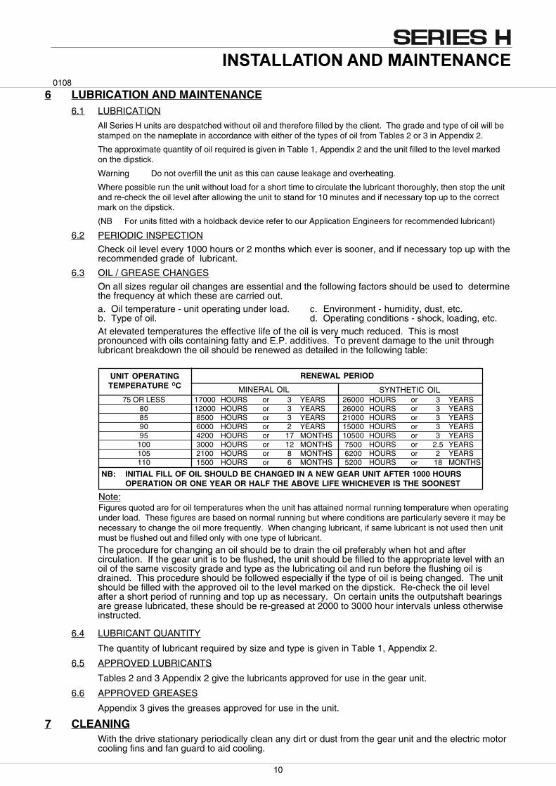
On all sizes regular oil changes are essential and the following factors should be used to determinethe frequency at which these are carried out.a. Oil temperature - unit operating under load. c. Environment - humidity, dust, etc.b. Type of oil. d. Operating conditions - shock, loading, etc.At elevated temperatures the effective life of the oil is very much reduced. This is mostpronounced with oils containing fatty and E.P. additives. To prevent damage to the unit throughlubricant breakdown the oil should be renewed as detailed in the following table:
The procedure for changing an oil should be to drain the oil preferably when hot and aftercirculation. If the gear unit is to be flushed, the unit should be filled to the appropriate level with anoil of the same viscosity grade and type as the lubricating oil and run before the flushing oil isdrained. This procedure should be followed especially if the type of oil is being changed. The unitshould be filled with the approved oil to the level marked on the dipstick. Re-check the oil levelafter a short period of running and top up as necessary. On certain units the outputshaft bearingsare grease lubricated, these should be re-greased at 2000 to 3000 hour intervals unless otherwiseinstructed.
6.4 LUBRICANT QUANTITY
The quantity of lubricant required by size and type is given in Table 1, Appendix 2.
6.5 APPROVED LUBRICANTS
Tables 2 and 3 Appendix 2 give the lubricants approved for use in the gear unit.
6.6 APPROVED GREASES
Appendix 3 gives the greases approved for use in the unit.
7 CLEANINGWith the drive stationary periodically clean any dirt or dust from the gear unit and the electric motorcooling fins and fan guard to aid cooling.
RENEWAL PERIOD
MINERAL OIL SYNTHETIC OIL
UNIT OPERATINGTEMPERATURE OC
75 OR LESS 17000 HOURS or 3 YEARS 26000 HOURS or 3 YEARS80 12000 HOURS or 3 YEARS 26000 HOURS or 3 YEARS85 8500 HOURS or 3 YEARS 21000 HOURS or 3 YEARS90 6000 HOURS or 2 YEARS 15000 HOURS or 3 YEARS95 4200 HOURS or 17 MONTHS 10500 HOURS or 3 YEARS
100 3000 HOURS or 12 MONTHS 7500 HOURS or 2.5 YEARS105 2100 HOURS or 8 MONTHS 6200 HOURS or 2 YEARS110 1500 HOURS or 6 MONTHS 5200 HOURS or 18 MONTHS
NB: INITIAL FILL OF OIL SHOULD BE CHANGED IN A NEW GEAR UNIT AFTER 1000 HOURSOPERATION OR ONE YEAR OR HALF THE ABOVE LIFE WHICHEVER IS THE SOONEST
Note:Figures quoted are for oil temperatures when the unit has attained normal running temperature when operatingunder load. These figures are based on normal running but where conditions are particularly severe it may benecessary to change the oil more frequently. When changing lubricant, if same lubricant is not used then unitmust be flushed out and filled only with one type of lubricant.
��� �� ��� ��� ���� �������
��
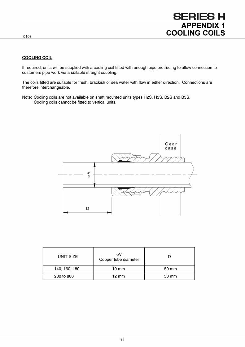
G e a rc a s e
D
øV
COOLING COIL
If required, units will be supplied with a cooling coil fitted with enough pipe protruding to allow connection tocustomers pipe work via a suitable straight coupling.
The coils fitted are suitable for fresh, brackish or sea water with flow in either direction. Connections aretherefore interchangeable.
Note: Cooling coils are not available on shaft mounted units types H2S, H3S, B2S and B3S.Cooling coils cannot be fitted to vertical units.
140, 160, 180 10 mm 50 mm
200 to 800 12 mm 50 mm
UNIT SIZE øVCopper tube diameter
D
�����������������
����
�
UnitType
UNIT SIZE
140 250225200180160
TABLE 1 LUBRICANT QUANTITY (Litres)
280 450400355315
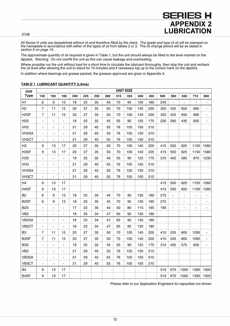
All Series H units are despatched without oil and therefore filled by the client. The grade and type of oil will be stamped onthe nameplate in accordance with either of the types of oil from tables 2 or 3. The oil change period will be as stated insection 6 on page 10.
The approximate quantity of oil required is given in Table 1, but the unit should always be filled to the level marked on thedipstick. Warning: Do not overfill the unit as this can cause leakage and overheating.
Where possible run the unit without load for a short time to circulate the lubricant thoroughly, then stop the unit and recheckthe oil level after allowing the unit to stand for 10 minutes and if necessary top up to the correct mark on the dipstick.
In addition where bearings are grease packed, the greases approved are given in Appendix 3.
������������ ���
����
560500 630 800710
Please refer to our Application Engineers for capacities not shown
H1 6 9 13 18 25 35 45 70 95 130 180 245 - - - -
H2 7 11 15 20 27 35 50 70 100 140 205 320 425 650 895 -
H2SF 7 11 15 20 27 35 50 70 100 140 205 320 425 650 895 -
H2S - - - 19 25 32 45 55 90 125 175 230 290 435 655 -
VH2 - - - 21 29 40 55 76 105 150 210
VH2SA - - - 21 29 40 55 76 105 150 210
VH2CT - - - 21 29 40 55 76 105 150 210
H3 9 13 17 20 27 35 50 70 100 140 205 415 550 825 1150 1580
H3SF 9 13 17 20 27 35 50 70 100 140 205 415 550 825 1150 1580
H3S - - - 19 25 32 45 55 90 125 175 315 405 585 870 1230
VH3 - - - 21 29 40 55 76 105 150 210
VH3SA - - - 21 29 40 55 76 105 150 210
VH3CT - - - 21 29 40 55 76 105 150 210
H4 9 13 17 415 550 825 1150 1580
H4SF 9 13 17 415 550 825 1150 1580
B2 6 9 13 18 25 35 45 70 95 130 180 275 - - - -
B2SF 6 9 13 18 25 35 45 70 95 130 180 275 - - - -
B2S - - - 17 22 30 40 50 80 115 165 190 - - - -
VB2 - - - 18 25 34 47 65 92 130 180
VB2SA - - - 18 25 34 47 65 92 130 180
VB2CT - - - 18 25 34 47 65 92 130 180
B3 7 11 15 20 27 35 50 70 100 140 205 410 535 800 1095 -
B3SF 7 11 15 20 27 35 50 70 100 140 205 410 535 800 1095 -
B3S - - - 19 25 32 45 55 90 125 175 315 405 575 835 -
VB3 - - - 21 29 40 55 76 105 150 210
VB3SA - - - 21 29 40 55 76 105 150 210
VB3CT - - - 21 29 40 55 76 105 150 210
B4 9 13 17 510 670 1000 1390 1920
B4SF 9 13 17 510 670 1000 1390 1920
��
LUBRICANTRANGESUPPLIER
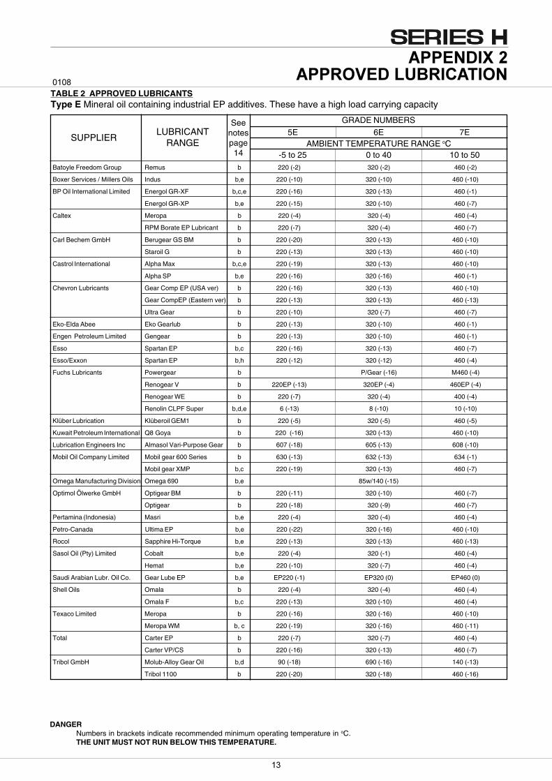
TABLE 2 APPROVED LUBRICANTSType E Mineral oil containing industrial EP additives. These have a high load carrying capacity
DANGERNumbers in brackets indicate recommended minimum operating temperature in oC.THE UNIT MUST NOT RUN BELOW THIS TEMPERATURE.
GRADE NUMBERS
AMBIENT TEMPERATURE RANGE oC7E6E5E
10 to 500 to 40-5 to 25Batoyle Freedom Group Remus b 220 (-2) 320 (-2) 460 (-2)
Boxer Services / Millers Oils Indus b,e 220 (-10) 320 (-10) 460 (-10)
BP Oil International Limited Energol GR-XF b,c,e 220 (-16) 320 (-13) 460 (-1)
Energol GR-XP b,e 220 (-15) 320 (-10) 460 (-7)
Caltex Meropa b 220 (-4) 320 (-4) 460 (-4)
RPM Borate EP Lubricant b 220 (-7) 320 (-4) 460 (-7)
Carl Bechem GmbH Berugear GS BM b 220 (-20) 320 (-13) 460 (-10)
Staroil G b 220 (-13) 320 (-13) 460 (-10)
Castrol International Alpha Max b,c,e 220 (-19) 320 (-13) 460 (-10)
Alpha SP b,e 220 (-16) 320 (-16) 460 (-1)
Chevron Lubricants Gear Comp EP (USA ver) b 220 (-16) 320 (-13) 460 (-10)
Gear CompEP (Eastern ver) b 220 (-13) 320 (-13) 460 (-13)
Ultra Gear b 220 (-10) 320 (-7) 460 (-7)
Eko-Elda Abee Eko Gearlub b 220 (-13) 320 (-10) 460 (-1)
Engen Petroleum Limited Gengear b 220 (-13) 320 (-10) 460 (-1)
Esso Spartan EP b,c 220 (-16) 320 (-13) 460 (-7)
Esso/Exxon Spartan EP b,h 220 (-12) 320 (-12) 460 (-4)
Fuchs Lubricants Powergear b P/Gear (-16) M460 (-4)
Renogear V b 220EP (-13) 320EP (-4) 460EP (-4)
Renogear WE b 220 (-7) 320 (-4) 400 (-4)
Renolin CLPF Super b,d,e 6 (-13) 8 (-10) 10 (-10)
Klüber Lubrication Klüberoil GEM1 b 220 (-5) 320 (-5) 460 (-5)
Kuwait Petroleum International Q8 Goya b 220 (-16) 320 (-13) 460 (-10)
Lubrication Engineers Inc Almasol Vari-Purpose Gear b 607 (-18) 605 (-13) 608 (-10)
Mobil Oil Company Limited Mobil gear 600 Series b 630 (-13) 632 (-13) 634 (-1)
Mobil gear XMP b,c 220 (-19) 320 (-13) 460 (-7)
Omega Manufacturing Division Omega 690 b,e 85w/140 (-15)
Optimol Ölwerke GmbH Optigear BM b 220 (-11) 320 (-10) 460 (-7)
Optigear b 220 (-18) 320 (-9) 460 (-7)
Pertamina (Indonesia) Masri b,e 220 (-4) 320 (-4) 460 (-4)
Petro-Canada Ultima EP b,e 220 (-22) 320 (-16) 460 (-10)
Rocol Sapphire Hi-Torque b,e 220 (-13) 320 (-13) 460 (-13)
Sasol Oil (Pty) Limited Cobalt b,e 220 (-4) 320 (-1) 460 (-4)
Hemat b,e 220 (-10) 320 (-7) 460 (-4)
Saudi Arabian Lubr. Oil Co. Gear Lube EP b,e EP220 (-1) EP320 (0) EP460 (0)
Shell Oils Omala b 220 (-4) 320 (-4) 460 (-4)
Omala F b,c 220 (-13) 320 (-10) 460 (-4)
Texaco Limited Meropa b 220 (-16) 320 (-16) 460 (-10)
Meropa WM b, c 220 (-19) 320 (-16) 460 (-11)
Total Carter EP b 220 (-7) 320 (-7) 460 (-4)
Carter VP/CS b 220 (-16) 320 (-13) 460 (-7)
Tribol GmbH Molub-Alloy Gear Oil b,d 90 (-18) 690 (-16) 140 (-13)
Tribol 1100 b 220 (-20) 320 (-18) 460 (-16)
Seenotespage
14
������� ������������ ���
����
��
LUBRICANTRANGESUPPLIER
GRADE NUMBERS
AMBIENT TEMPERATURE RANGE oC7H6H5H
10 to 500 to 45-10 to 30
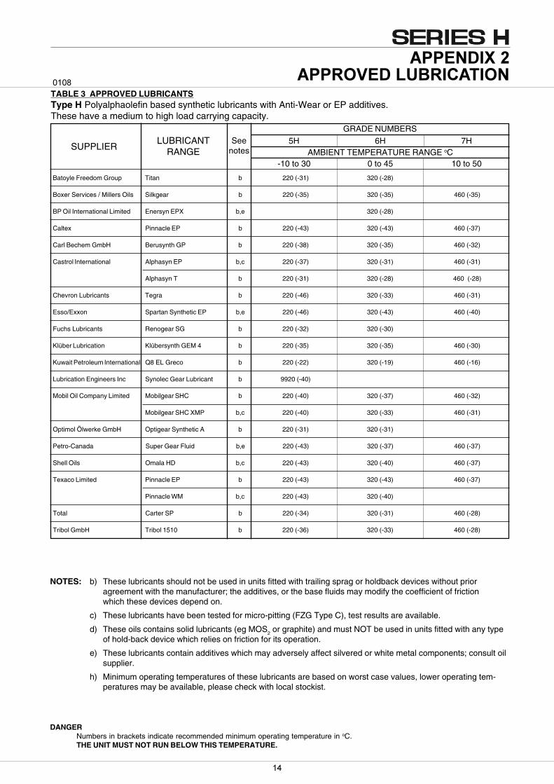
TABLE 3 APPROVED LUBRICANTSType H Polyalphaolefin based synthetic lubricants with Anti-Wear or EP additives.These have a medium to high load carrying capacity.
Seenotes
DANGERNumbers in brackets indicate recommended minimum operating temperature in oC.THE UNIT MUST NOT RUN BELOW THIS TEMPERATURE.
Batoyle Freedom Group Titan b 220 (-31) 320 (-28)
Boxer Services / Millers Oils Silkgear b 220 (-35) 320 (-35) 460 (-35)
BP Oil International Limited Enersyn EPX b,e 320 (-28)
Caltex Pinnacle EP b 220 (-43) 320 (-43) 460 (-37)
Carl Bechem GmbH Berusynth GP b 220 (-38) 320 (-35) 460 (-32)
Castrol International Alphasyn EP b,c 220 (-37) 320 (-31) 460 (-31)
Alphasyn T b 220 (-31) 320 (-28) 460 (-28)
Chevron Lubricants Tegra b 220 (-46) 320 (-33) 460 (-31)
Esso/Exxon Spartan Synthetic EP b,e 220 (-46) 320 (-43) 460 (-40)
Fuchs Lubricants Renogear SG b 220 (-32) 320 (-30)
Klüber Lubrication Klübersynth GEM 4 b 220 (-35) 320 (-35) 460 (-30)
Kuwait Petroleum International Q8 EL Greco b 220 (-22) 320 (-19) 460 (-16)
Lubrication Engineers Inc Synolec Gear Lubricant b 9920 (-40)
Mobil Oil Company Limited Mobilgear SHC b 220 (-40) 320 (-37) 460 (-32)
Mobilgear SHC XMP b,c 220 (-40) 320 (-33) 460 (-31)
Optimol Ölwerke GmbH Optigear Synthetic A b 220 (-31) 320 (-31)
Petro-Canada Super Gear Fluid b,e 220 (-43) 320 (-37) 460 (-37)
Shell Oils Omala HD b,c 220 (-43) 320 (-40) 460 (-37)
Texaco Limited Pinnacle EP b 220 (-43) 320 (-43) 460 (-37)
Pinnacle WM b,c 220 (-43) 320 (-40)
Total Carter SP b 220 (-34) 320 (-31) 460 (-28)
Tribol GmbH Tribol 1510 b 220 (-36) 320 (-33) 460 (-28)
NOTES: b) These lubricants should not be used in units fitted with trailing sprag or holdback devices without prioragreement with the manufacturer; the additives, or the base fluids may modify the coefficient of frictionwhich these devices depend on.
c) These lubricants have been tested for micro-pitting (FZG Type C), test results are available.
d) These oils contains solid lubricants (eg MOS2 or graphite) and must NOT be used in units fitted with any typeof hold-back device which relies on friction for its operation.
e) These lubricants contain additives which may adversely affect silvered or white metal components; consult oilsupplier.
h) Minimum operating temperatures of these lubricants are based on worst case values, lower operating tem-peratures may be available, please check with local stockist.
������� ������������ ���
����
��
������� ��������� ������ ���
����
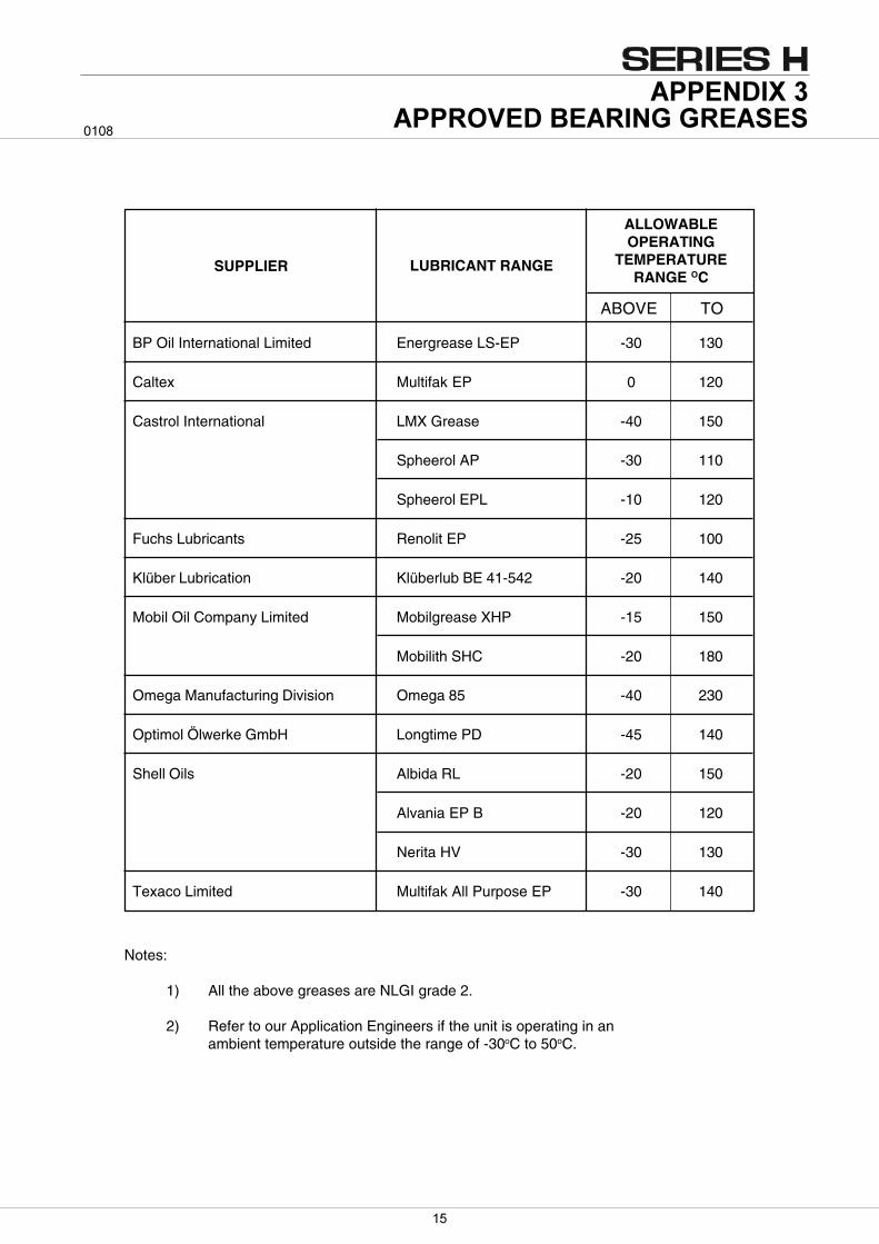
Notes:
1) All the above greases are NLGI grade 2.
2) Refer to our Application Engineers if the unit is operating in anambient temperature outside the range of -30oC to 50oC.
ABOVE TO
ALLOWABLEOPERATING
TEMPERATURERANGE OC
SUPPLIER LUBRICANT RANGE
BP Oil International Limited Energrease LS-EP -30 130
Caltex Multifak EP 0 120
Castrol International LMX Grease -40 150
Spheerol AP -30 110
Spheerol EPL -10 120
Fuchs Lubricants Renolit EP -25 100
Klüber Lubrication Klüberlub BE 41-542 -20 140
Mobil Oil Company Limited Mobilgrease XHP -15 150
Mobilith SHC -20 180
Omega Manufacturing Division Omega 85 -40 230
Optimol Ölwerke GmbH Longtime PD -45 140
Shell Oils Albida RL -20 150
Alvania EP B -20 120
Nerita HV -30 130
Texaco Limited Multifak All Purpose EP -30 140
��
AFigure 1
Figure 2
Figure 3
Figure 4
A
A1
1
3
4 2
2
3
4
B
B
B
Figure 51
2
3
4
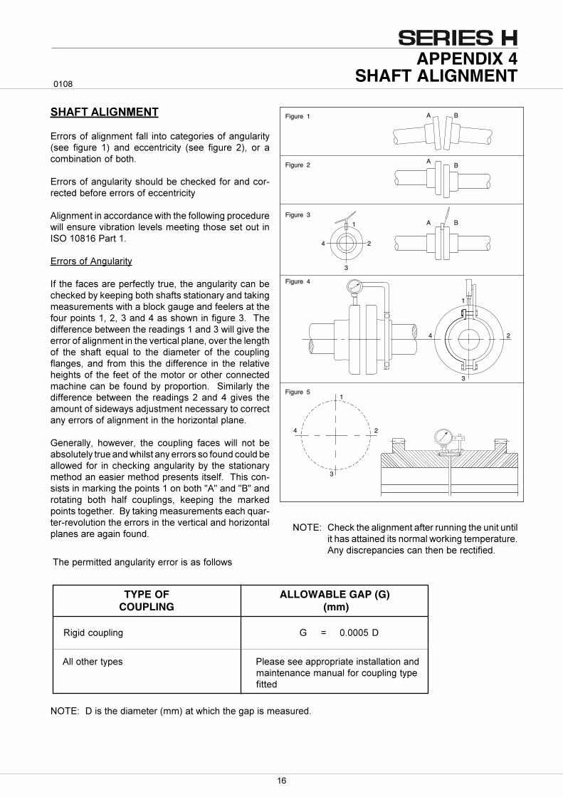
=(�$ 8����������������������������������������������� ���������� ������������������������������� �������� ���������������������
������������ ��
$���� ������������������ ������������ �������������* ��� ������ 7.� ���� ����������� * ��� ������ <.�� ��� �������������������
$���� �������������� ����������������������������3������������������� ��������������
��������������������������������������������������� ����������������� ����������� �� ������� �'�(�7-57)�?����7�
$���� �������������
'���������� ���������������������������������������������������������������� ���� � ��������������������� ������� ���������������������������� ���������������� �7��<��@�����A�� � ������������@��������������������������������� �7�����@�������������������������������������������������������������������� ���� ����� �%���� ��� ���� �������� ��� ���� ������������� ������ ����� �� � �������������� �� ���� ������������ ���� ���� �������� ������������������������������������������ �������������������� ��������� �������������������� ���� ������ �<�����A���� � ������������� ���� ���4� ���������� ����������������������� ����������������������"������������
>���������� �������� ���� �������� ���� � ��� ���� ���� ������������������� ����������� � ����������������������� ���� ����������������������� ���� �������������������� ������������� ��� �� �������� ����3 � ������������������ �7���������B�B�����B!B������������ ����� ����� ������� �� ������� ���� ���������� ������������!����������� ������� ������%���3���3������������������� ����������������������"���������� ����������������
TYPE OFCOUPLING
ALLOWABLE GAP (G) (mm)
#���������� > C -�---, 9
����������������������������� �� ������
=(�$ 9� �������������*��.���������������� ���� �����
APPENDIX 4SHAFT ALIGNMENT
0108
�������������� ?��� �� ��������������� ���������������������������������������������������
��
APPENDIX 4SHAFT ALIGNMENT
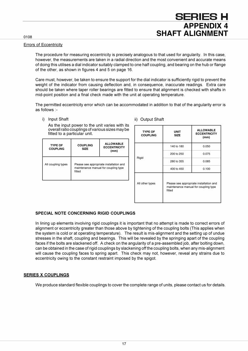
$���� ����$���������
��������������������� ���������������� ����� ������������ ���������� �������������������'���� ��� ����������������� ������� ��������������������������������������� ����������������������������� ���������� ���� � ��������������� ���������������������������������������������������������������������������������� � ����������� �A�����,���������7)�
8������ ������������������������� �������� ��������������������������� � �������������������������������������������������������� ������������������ ����� �%������� ���������������� ���$&�������� ��������������������������������������� ���������������� ������������������ ������������ ���� ����3������� �������������������������������������������������������������
���������������������������������������������������������������������������������������������� � ������ � 3
������������� ��
����������� �����������&����������� ����������������������������������� ������ ����������� ���������� �
�������� ���� ��� � ������������ ��
'����������������� �������������������� ��� �������������������������� ���������������������� ������������������������������������������ ��������������������������������������� �*�� ������ �������� � ���� ��������������������������������.���������� ���� �� 3����������������� ����������������� ��� � ������� ������������������������ ����� ����������������������� ������������������������������� ����������� ����� ������������������������������������������������3� �������4�������������������������������������������� ���������������� ���� ����������������������������� ����������� 3�������������� ������������������ ���� ��������������� ����������������������������������� ���� �������������������������������� ������� ��������� ���������� �����
0108
i) Input Shaft
As the input power to the unit varies with itsoverall ratio couplings of various sizes may befitted to a particular unit.
ii) Output Shaft
ALLOWABLEECCENTRICITY
(mm)
TYPE OFCOUPLING
UNITSIZE
ALLOWABLEECCENTRICITY
(mm)
TYPE OFCOUPLING
COUPLINGSIZE
140 to 180 0.050
200 to 250 0.075
280 to 355 0.085
400 to 450 0.100
!!"#$�%#&��' �!�('�'��(��%"�%)(#�)*'#(!!(#)"*(* �()*#�*(*+��(*,(!-"%+",�!)*.#&��-)##�
Rigid
!!+",�!)*.#&��' �!�('�'��(��%"�%)(#�)*'#(!!(#)"*(* �()*#�*(*+��(*,(!-"%+",�!)*.#&��-)##�
��
��������� ����
����
� ��������
������ ����
�������
������������
���������
���������
���������
��������
�������
BEARINGS
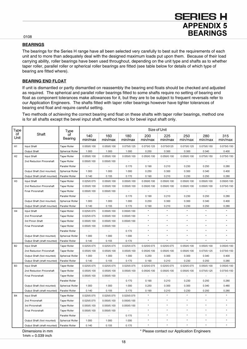
The bearings for the Series H range have all been selected very carefully to best suit the requirements of eachunit and to more than adequately deal with the designed maximum loads put upon them. Because of their loadcarrying ability, roller bearings have been used throughout, depending on the unit type and shafts as to whethertaper roller, parallel roller or spherical roller bearings are fitted (see table below for details of which type ofbearing are fitted where).
BEARING END FLOAT
If unit is dismantled or partly dismantled on reassembly the bearing end floats should be checked and adjustedas required. The spherical and parallel roller bearings fitted to some shafts require no setting of bearing endfloat as component tolerances make allowances for it, but they are to be subject to frequent reversals refer toour Application Engineers. The shafts fitted with taper roller bearings however have tighter tolerances ofbearing end float and require careful setting.
Two methods of achieving the correct bearing end float on these shafts with taper roller bearings, method oneis for all shafts except the bevel input shaft, method two is for bevel input shaft only.
Dimensions in mm * Please contact our Application Engineers1mm = 0.039 inch
�� ������� � ����������� ����������� ����������� ����������� ����������� ���������� ����������� ����������� �����������
�������� � �������������� ����� ����� ����� ����� ����� ����� ����� �����
�� ������� � ����������� ����������� ����������� ����������� ����������� ����������� ����������� ����������� �����������
������������ �����!�� � ����������� ����������� ����������� " " " " " "
������������� " " ����� ���#� ����� ����� ����� ���$�
�������� �% ���&������' �������������� ����� ����� ����� ����� ����� ����� ����� �����
�������� �%!�� �&������' ������������� ����� ����� ����� ���#� ����� ����� ����� ���$�
�� ������� � ����������� ����������� ����������� ����������� ����������� ����������� ����������� ����������� �����������
������������ �����!�� � ����������� ����������� ����������� ����������� ����������� ����������� ����������� ����������� �����������
(���� �����!�� � ����������� ����������� ����������� " " " " " "
������������� " " ����� ���#� ����� ����� ����� ���$�
�������� �% ���&������' �������������� ����� ����� ����� ����� ����� ����� ����� �����
�������� �%!�� �&������' ������������� ����� ����� ����� ���#� ����� ����� ����� ���$�
�� ������� � ����������� ����������� ����������� ����������� ) ) ) ) )
��� �����!�� � ����������� ����������� ����������� ����������� ) ) ) ) )
��� ������� � ����������� ����������� ����������� ����������� ) ) ) ) )
(���� �����!�� � ����������� ����������� ����������� " ) ) ) ) )
������������� " " ����� ) ) ) ) )
�������� �% ���&������' �������������� ����� ����� ����� ) ) ) ) )
�������� �%!�� �&������' ������������� ����� ����� ����� ) ) ) ) )
*� ������� � ����������� ����������� ����������� ����������� ����������� ����������� ����������� ����������� �����������
������������ �����!�� � ����������� ����������� ����������� ����������� ����������� ����������� ����������� ����������� �����������
�������� �% ���&������' �������������� ����� ����� ����� ����� ����� ����� ����� �����
�������� �%!�� �&������' ������������� ����� ����� ����� ���#� ����� ����� ����� ���$�
*� ������� � ����������� ����������� ����������� ����������� ����������� ����������� ����������� ����������� �����������
������������ �����!�� � ����������� ����������� ����������� ����������� ����������� ����������� ����������� ����������� �����������
(���� �����!�� � ����������� ����������� ����������� " " " " " "
������������� " " ����� ���#� ����� ����� ����� ���$�
�������� �% ���&������' �������������� ����� ����� ����� ����� ����� ����� ����� ���$�
�������� �%!�� �&������' ������������� ����� ����� ����� ���#� ����� ����� ����� ���$�
*� ������� � ����������� ����������� ����������� ����������� ) ) ) ) )
��� �����!�� � ����������� ����������� ����������� ����������� ) ) ) ) )
��� �����!�� � ����������� ����������� ����������� ����������� ) ) ) ) )
(���� �����!�� � ����������� ����������� ����������� " ) ) ) ) )
������������� " " ����� ) ) ) ) )
�������� �% ���&������' �������������� ����� ����� ����� ) ) ) ) )
�������� �%!�� �&������' ������������� ����� ����� ����� ) ) ) ) )
250min/max
280min/max
315min/max
�
��������� ����
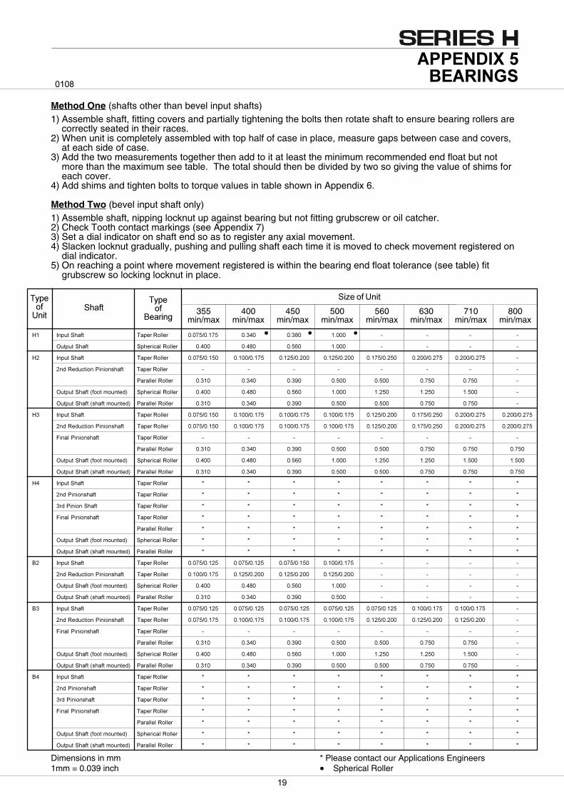
Dimensions in mm * Please contact our Applications Engineers1mm = 0.039 inch Spherical Roller
����
Method One (shafts other than bevel input shafts)1) Assemble shaft, fitting covers and partially tightening the bolts then rotate shaft to ensure bearing rollers are
correctly seated in their races.2) When unit is completely assembled with top half of case in place, measure gaps between case and covers,
at each side of case.3) Add the two measurements together then add to it at least the minimum recommended end float but not
more than the maximum see table. The total should then be divided by two so giving the value of shims foreach cover.
4) Add shims and tighten bolts to torque values in table shown in Appendix 6.
Method Two (bevel input shaft only)1) Assemble shaft, nipping locknut up against bearing but not fitting grubscrew or oil catcher.2) Check Tooth contact markings (see Appendix 7)3) Set a dial indicator on shaft end so as to register any axial movement.4) Slacken locknut gradually, pushing and pulling shaft each time it is moved to check movement registered on
dial indicator.5) On reaching a point where movement registered is within the bearing end float tolerance (see table) fit
grubscrew so locking locknut in place.
� ��������
������ ����
�������
������������
355min/max
400min/max
450min/max
500min/max
560min/max
630min/max
710min/max
800min/max
�� ������� � ����������� ����������� ����� ���$� ����� " " " "
�������� � �������������� ����� ���$� ���+� ����� " " " "
�� ������� � ����������� ����������� ����������� ����������� ����������� ����������� ����������� ����������� "
������������ �����!�� � ����������� " " " " " " " "
������������� ����� ����� ���#� ����� ����� ����� ����� "
�������� �% ���&������' �������������� ����� ���$� ���+� ����� ����� ����� ����� "
�������� �%!�� �&������' ������������� ����� ����� ���#� ����� ����� ����� ����� "
�� ������� � ����������� ����������� ����������� ����������� ����������� ����������� ����������� ����������� �����������
������������ �����!�� � ����������� ����������� ����������� ����������� ����������� ����������� ����������� ����������� �����������
(���� �����!�� � ����������� " " " " " " " "
������������� ����� ����� ���#� ����� ����� ����� ����� �����
�������� �% ���&������' �������������� ����� ���$� ���+� ����� ����� ����� ����� �����
�������� �%!�� �&������' ������������� ����� ����� ���#� ����� ����� ����� ����� �����
�� ������� � ����������� ) ) ) ) ) ) ) )
��� �����!�� � ����������� ) ) ) ) ) ) ) )
��� ������� � ����������� ) ) ) ) ) ) ) )
(���� �����!�� � ����������� ) ) ) ) ) ) ) )
������������� ) ) ) ) ) ) ) )
�������� �% ���&������' �������������� ) ) ) ) ) ) ) )
�������� �%!�� �&������' ������������� ) ) ) ) ) ) ) )
*� ������� � ����������� ����������� ����������� ����������� ����������� " " " "
������������ �����!�� � ����������� ����������� ����������� ����������� ����������� " " " "
�������� �% ���&������' �������������� ����� ���$� ���+� ����� " " " "
�������� �%!�� �&������' ������������� ����� ����� ���#� ����� " " " "
*� ������� � ����������� ����������� ����������� ����������� ����������� ����������� ����������� ����������� "
������������ �����!�� � ����������� ����������� ����������� ����������� ����������� ����������� ����������� ����������� "
(���� �����!�� � ����������� " " " " " " " "
������������� ����� ����� ���#� ����� ����� ����� ����� "
�������� �% ���&������' �������������� ����� ���$� ���+� ����� ����� ����� ����� "
�������� �%!�� �&������' ������������� ����� ����� ���#� ����� ����� ����� ����� "
*� ������� � ����������� ) ) ) ) ) ) ) )
��� �����!�� � ����������� ) ) ) ) ) ) ) )
��� �����!�� � ����������� ) ) ) ) ) ) ) )
(���� �����!�� � ����������� ) ) ) ) ) ) ) )
������������� ) ) ) ) ) ) ) )
�������� �% ���&������' �������������� ) ) ) ) ) ) ) )
�������� �%!�� �&������' ������������� ) ) ) ) ) ) ) )
�
140 H1 and - - - M10 45 400 M8 25 220B2 - - - M10 50 440H2 and - - - M10 45 400 M8 25 220B3 - - - M10 50 440H3, H4 - - - M10 45 400 M8 25 220and B4 - - - M10 50 440
160 H1 and - - - M12 77 680 M8 25 220B2 - - - M10 50 440H2 and - - - M10 45 400 M8 25 220B3 - - - M12 77 680 M10 50 440H3, H4 - - - M10 45 400 M8 25 220and B4 - - - M12 77 680 M10 50 440
180 H1 and - - - M10 45 400 M8 25 220B2 - - - M12 77 680 M10 50 440
- - - M16 180 1600H2 and - - - M10 45 400 M8 25 220B3 - - - M12 77 680 M10 50 440
- - - M16 180 1600H3, H4 - - - M10 45 400 M8 25 220and B4 - - - M12 77 680 M10 50 440
- - - M16 180 1600200 H1 and M12 85 750 M12 45 400 M8 25 220
B2 M16 220 1950 M16 180 1600 M10 50 440H2, H3 M12 85 750 M12 45 400 M8 25 220and B3 M16 220 1950 M16 180 1600 M10 50 440
225 H1 and M12 85 750 M12 77 680 M10 50 440B2 M16 220 1950 M16 180 1600 M12 85 750
M20 440 3890 M20 315 2790H2, H3 M12 85 750 M12 77 680 M8 25 220and B3 M16 220 1950 M16 180 1600 M10 50 440
M20 440 3890 M20 315 2790 M12 85 750250 H1 and M16 220 1950 M16 180 1600 M10 50 440
B2 M20 440 3890 M20 315 2790 M12 85 750H2, H3 M16 220 1950 M16 180 1600 M8 25 220and B3 M20 440 3890 M20 315 2790 M10 50 440
M12 85 750280 H1 and M16 220 1950 M16 180 1600 M10 50 440
B2 M20 440 3890 M20 315 2790 M12 85 750M24 760 6730 M24 550 4870
H2, H3 M16 220 1950 M16 180 1600 M8 25 220and B3 M20 440 3890 M20 315 2790 M10 50 440
M24 760 6730 M24 550 4870 M12 85 750315 H1 and M20 440 3890 M20 315 2790 M12 85 750
B2 M24 760 6730 M24 550 4870 M16 200 1770M27-M24 760 6730 M27-M24 550 4870
H2, H3 M20 440 3890 M20 315 2790 M10 50 440and B3 M24 760 6730 M24 550 4870 M12 85 750
M27-M24 760 6730 M27-24 550 4870 M16 200 1770355 H1 and M20 440 3890 M20 315 2790 M12 85 750
B2 M24 760 6730 M24 550 4870 M16 200 1770M30 1520 13450 M30 1100 9740
H2, H3 M20 440 3890 M20 315 2790 M10 50 440and B3 M24 760 6730 M24 550 4870 M12 85 750
M30 1520 13450 M30 1100 9740 M16 200 1770400 H1 and M24 760 6730 M24 550 4870 M12 85 750
B2 M30 1520 13450 M30 1100 9740 M16 200 1770M20 350 3100
H2, H3 M24 760 6730 M24 550 4870 M12 85 750and B3 M30 1520 13450 M30 1100 9740 M20 350 3100
450 H1 and M24 760 6730 M24 550 4870 M16 200 1770B2 M30 1520 13450 M30 1100 9740 M20 350 3100
M36 2690 23800 M36 1950 17260H2, H3 M24 760 6730 M24 550 4870 M12 85 750and B3 M30 1520 13450 M30 1100 9740 M16 200 1770
M36 2690 23800 M36 1950 17260 M20 350 3100
����������������������
����
ThreadSize
TorqueNm
Torquelbf-in
ThreadSize
TorqueNm
Torquelbf-in
ThreadSize
TorqueNm
Torquelbf-in
Case Joint Studs fitted with NylocNuts
Case Joint Studs fitted with PlainNuts and Loctite Cover and Housing Bolts
UnitType
UnitSize
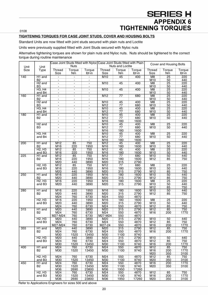
TIGHTENING TORQUES FOR CASE JOINT STUDS, COVER AND HOUSING BOLTS
Standard Units are now fitted with joint studs secured with plain nuts and Loctite
Units were previously supplied fitted with Joint Studs secured with Nyloc nuts
Alternative tightening torques are shown for plain nuts and Nyloc nuts. Nuts should be tightened to the correcttorque during routine maintenance
Refer to Applications Engineers for sizes 500 and above
�
Bottom sideLow heel contactBottom sideLow heel contact
Bottom sideCentral toe contactBottom sideCentral toe contact
Bottom sideHigh toe contactBottom sideHigh toe contact
Bottom sideHigh heel contactBottom sideHigh heel contact
Bottom sideCentral toe contactBottom sideCentral toe contact
Bottom sideLow toe contactBottom sideLow toe contact
Top sideLow toe contactTop sideLow toe contact
Top sideCentral toe contactTop sideCentral toe contact
Top sideHigh heel contactTop sideHigh heel contact
Top sideHigh toe contactTop sideHigh toe contact
ErrorError
Top sideCentral toe contactTop sideCentral toe contact
Top sideLow heel contactTop sideLow heel contact
Correct Marking
Incorrect Marking Incorrect Marking
Pinion member left hand in all cases shown
Move pinion out Move pinion in
��������� ��
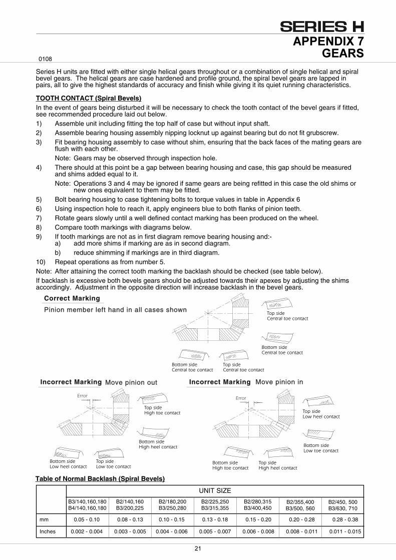
Series H units are fitted with either single helical gears throughout or a combination of single helical and spiralbevel gears. The helical gears are case hardened and profile ground, the spiral bevel gears are lapped inpairs, all to give the highest standards of accuracy and finish while giving it its quiet running characteristics.
TOOTH CONTACT (Spiral Bevels)In the event of gears being disturbed it will be necessary to check the tooth contact of the bevel gears if fitted,see recommended procedure laid out below.1) Assemble unit including fitting the top half of case but without input shaft.2) Assemble bearing housing assembly nipping locknut up against bearing but do not fit grubscrew.3) Fit bearing housing assembly to case without shim, ensuring that the back faces of the mating gears are
flush with each other.Note: Gears may be observed through inspection hole.
4) There should at this point be a gap between bearing housing and case, this gap should be measuredand shims added equal to it.Note: Operations 3 and 4 may be ignored if same gears are being refitted in this case the old shims or
new ones equivalent to them may be fitted.5) Bolt bearing housing to case tightening bolts to torque values in table in Appendix 66) Using inspection hole to reach it, apply engineers blue to both flanks of pinion teeth.7) Rotate gears slowly until a well defined contact marking has been produced on the wheel.8) Compare tooth markings with diagrams below.9) If tooth markings are not as in first diagram remove bearing housing and:-
a) add more shims if marking are as in second diagram.b) reduce shimming if markings are in third diagram.
10) Repeat operations as from number 5.Note: After attaining the correct tooth marking the backlash should be checked (see table below).If backlash is excessive both bevels gears should be adjusted towards their apexes by adjusting the shimsaccordingly. Adjustment in the opposite direction will increase backlash in the bevel gears.
����
mm 0.05 - 0.10 0.08 - 0.13 0.10 - 0.15 0.13 - 0.18 0.15 - 0.20 0.20 - 0.28 0.28 - 0.38
Inches 0.002 - 0.004 0.003 - 0.005 0.004 - 0.006 0.005 - 0.007 0.006 - 0.008 0.008 - 0.011 0.011 - 0.015
B3/140,160,180B4/140,160,180
B2/140,160B3/200,225
B2/180,200B3/250,280
B2/225,250B3/315,355
B2/280,315B3/400,450
B2/355,400B3/500, 560
B2/450, 500B3/630, 710
UNIT SIZE
Table of Normal Backlash (Spiral Bevels)

�����
www.benzlers.com
www.radicon.com
AUSTRALIA
Radicon Transmission (Australia) PTY Ltd
AustraliaTel: +61 421 822 315
EUROPE
Benzler TBA BVJachthavenweg 2 NL-5928 NT Venlo
GermanyTel: 0800 350 40 00Fax: 0800 350 40 01
ItalyTel: +39 02 824 3511
Netherlands & the rest of EuropeTel: +31 77 324 59 00Fax: +31 77 324 59 01
INDIA
Elecon. Engineering Company Ltd.Anand Sojitra RoadVallabh Vidyanagar388120 GujaratIndia
Tel: +91 2692 236513
DENMARK
Benzler Transmission A/SDalager 1DK-2605 Brøndby, Denmark
Tel: +45 36 34 03 00Fax: +45 36 77 02 42
FINLAND
Oy Benzler ABVanha Talvitie 3CFI-00580 Helsingfors, Finland
Tel: +358 9 340 1716Fax: +358 10 296 2072
SWEDEN & NORWAY
AB BenzlersPorfyrgatan254 68 HelsingborgSweden
Tel: +46 42 18 68 00Fax: +46 42 21 88 03
THAILAND
Radicon Transmission (Thailand) Ltd700/43 Moo 6Amata Nakorn Industrial EstateTumbol KlongtumruMuang, Chonburi 20000Thailand
Tel: +66 3845 9044Fax: +66 3821 3655
UNITED KINGDOM
Radicon Transmission UK LtdUnit J3Lowfields Business Park, Lowfields Way, EllandWest Yorkshire, HX5 9DA
Tel: +44 1484 465 800 Fax: +44 1484 465 801
USA
Radicon Drive Systems, Inc.2475 Alft Lane ElginChicagoIllinois60124USA
Tel: +1 847 593 9910Fax: +1 847 593 9950
CONTACT US

Benzlers
Denmark +45 36 340300
Finland +358 9 3401716
Germany +49 800 3504000
Italy +39 02 824 3511
Sweden +46 42 186800
The Netherlands +31 77 3245900
www.benzlers.com
Radicon
Thailand +66 38459044
United Kingdom +44 1484 465800
USA +1 847 5939910
www.radicon.com