
Series GM - Northern Plumbing
47
GM Boilers Series Gas Installation, Operation & Maintenance Manual
Transcript of Series GM - Northern Plumbing

GMBoilers
SeriesGas
Installation,Operation &MaintenanceManual

USING THIS MANUAL 1A. INSTALLATION SEQUENCE . . . . . . . . . . . . .1B. SPECIAL ATTENTION BOXES . . . . . . . . . . . .1
1. PREINSTALLATION 2
A. ACCESSIBILITY CLEARANCES . . . . . . . . . . .2B. CLEARANCE FROM COMBUSTIBLE
CONSTRUCTION . . . . . . . . . . . . . . . . . . . . . .2C. COMBUSTION AND VENTILATION AIR . . . .2
D. INSTALLATION SURVEY . . . . . . . . . . . . . . . .5
E. CIRCULATORS . . . . . . . . . . . . . . . . . . . . . . . .5
F. PLANNING THE LAYOUT . . . . . . . . . . . . . . . .5
2. BOILER SET-UP 6
3. WATER PIPING AND CONTROLS 7A. BOILER SUPPLY AND RETURN . . . . . . . . . . .7B. SAFETY RELIEF VALVE . . . . . . . . . . . . . . . . .8C. PIPING FOR ZONED SYSTEMS . . . . . . . . . . .9D. EXPANSION TANK . . . . . . . . . . . . . . . . . . . .10E. INDIRECT-FIRED WATER HEATER . . . . . . .10F. FREEZE PROTECTION . . . . . . . . . . . . . . . . .10
4. VENTING 11A. DRAFT HOOD . . . . . . . . . . . . . . . . . . . . . . .11B. AUTOMATIC VENT DAMPER
INSTALLATION – GENERAL . . . . . . . . . . . .12C. VENT PIPING AND CHIMNEY . . . . . . . . . . .12D. BOILER REMOVAL FROM COMMON
VENTING SYSTEM . . . . . . . . . . . . . . . . . . .13
5. GAS PIPING 14
6. ELECTRICAL 16A. WIRING . . . . . . . . . . . . . . . . . . . . . . . . . . . . .16B. CIRCULATOR/ZONE VALVE WIRING . . . . . .16C. LOW WATER CUTOFF . . . . . . . . . . . . . . . . .16
7. CSD CODE REQUIREMENTS 23A. GENERAL . . . . . . . . . . . . . . . . . . . . . . . . . . .23B. CSD PART CF REQUIREMENTS . . . . . . . . .23C. CSD PART CW REQUIREMENTS . . . . . . . .23D. CSD MODULAR AND MULTIPLE BOILER
REQUIREMENTS . . . . . . . . . . . . . . . . . . . . .23E. CSD PART CE ELECTRICAL
REQUIREMENTS . . . . . . . . . . . . . . . . . . . . .24
8. START-UP PROCEDURES 25A. COMPLETING THE INSTALLATION . . . . . . .25B. CONTROL DESCRIPTIONS . . . . . . . . . . . . .30C. ADJUSTMENT OF GAS PRESSURE
REGULATOR . . . . . . . . . . . . . . . . . . . . . . . . .30D. CHECKING BURNER INPUT . . . . . . . . . . . . .30E. CHECK-OUT PROCEDURE . . . . . . . . . . . . . .31
9. TROUBLESHOOTING 32A. SHUT-DOWN CAUSED BY PILOT OUTAGE,
VENT SAFETY SHUTOFF SWITCH ORFLAME ROLLOUT SAFETY SHUTOFFSWITCH . . . . . . . . . . . . . . . . . . . . . . . . . . . .32
B. TROUBLESHOOTING GUIDES . . . . . . . . . .32
10. MAINTENANCE 35A. GENERAL . . . . . . . . . . . . . . . . . . . . . . . . . . .36B. DAILY (WITH BOILER IN USE) . . . . . . . . . . .36C. WEEKLY (WITH BOILER IN USE) . . . . . . . . .36D. MONTHLY (WITH BOILER IN USE) . . . . . . .36E. ANNUALLY (BEFORE START OF HEATING
SEASON) . . . . . . . . . . . . . . . . . . . . . . . . . . .37
11. BOILER DIMENSIONS & RATINGS 38
12. REPAIR PARTS 39A. BASE . . . . . . . . . . . . . . . . . . . . . . . . . . . . . . .39B. GAS MANIFOLD, ORIFICE SPUDS, AND
MAIN BURNERS . . . . . . . . . . . . . . . . . . . . . .40C. BLOCK AND FLUE COLLECTOR . . . . . . . . .41D. JACKET . . . . . . . . . . . . . . . . . . . . . . . . . . . .42E. CONTROLS, DRAFT HOOD AND
AUTOMATIC VENT DAMPER . . . . . . . . . . .43
TABLE OF CONTENTS
TABLE OF CONTENTS

1
A. INSTALLATION SEQUENCE
Follow the installation instructions provided in thismanual in the order shown. The order of theseinstructions have been set in order to provide theinstaller with a logical sequence of steps that willminimize potential interferences and maximize safetyduring boiler installation.
B. SPECIAL ATTENTION BOXESThroughout this manual you will see special attentionboxes intended to supplement the instructions and makespecial notice of potential hazards. These categoriesmean, in the judgment of PB Heat, LLC:
Indicates special attention is needed, but not directlyrelated to potential personal injury or propertydamage.
NOTICE
Indicates a condition or hazard which will or cancause minor personal injury or property damage.
CAUTION
DANGERIndicates a condition or hazard which will causesevere personal injury, death or major propertydamage.
USING THIS MANUAL
USING THIS MANUAL
Indicates a condition or hazard which may causesevere personal injury, death or major propertydamage.
WARNING
2
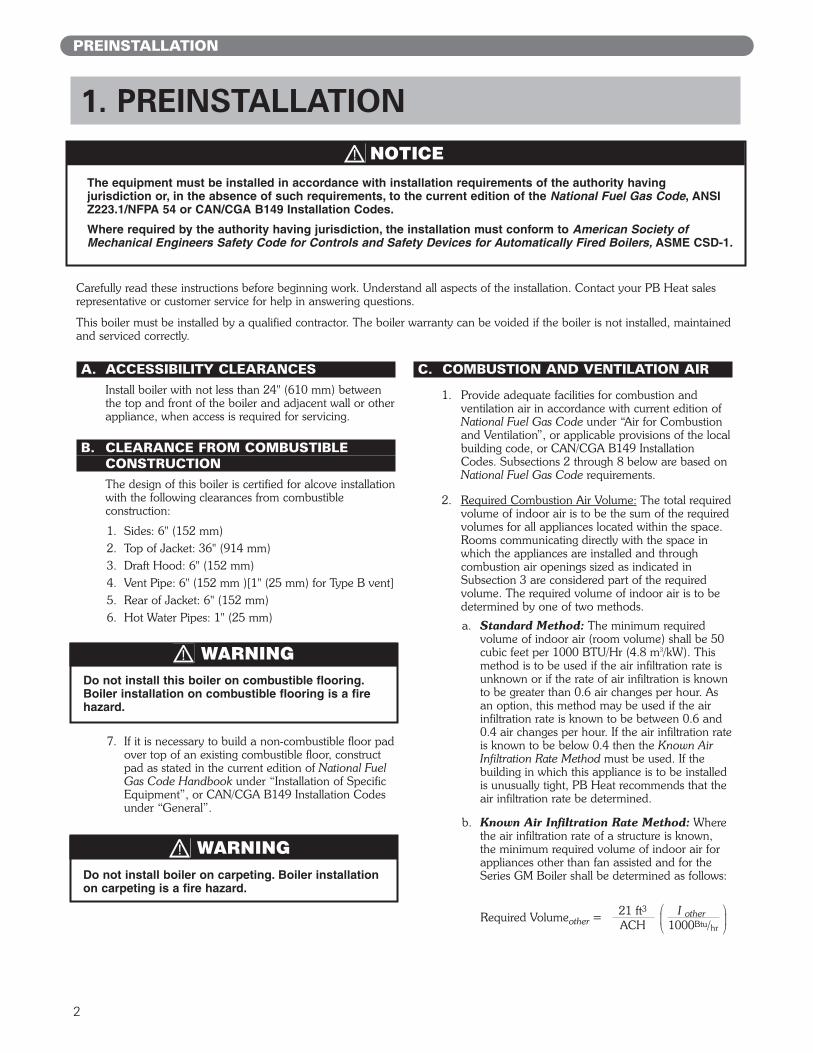
The equipment must be installed in accordance with installation requirements of the authority having jurisdiction or, in the absence of such requirements, to the current edition of the National Fuel Gas Code, ANSIZ223.1/NFPA 54 or CAN/CGA B149 Installation Codes.
Where required by the authority having jurisdiction, the installation must conform to American Society ofMechanical Engineers Safety Code for Controls and Safety Devices for Automatically Fired Boilers, ASME CSD-1.
NOTICE
A. ACCESSIBILITY CLEARANCESInstall boiler with not less than 24" (610 mm) betweenthe top and front of the boiler and adjacent wall or otherappliance, when access is required for servicing.
B. CLEARANCE FROM COMBUSTIBLE CONSTRUCTIONThe design of this boiler is certified for alcove installationwith the following clearances from combustibleconstruction:
1. Sides: 6" (152 mm)2. Top of Jacket: 36" (914 mm)3. Draft Hood: 6" (152 mm)4. Vent Pipe: 6" (152 mm )[1" (25 mm) for Type B vent]5. Rear of Jacket: 6" (152 mm)6. Hot Water Pipes: 1" (25 mm)
7. If it is necessary to build a non-combustible floor padover top of an existing combustible floor, constructpad as stated in the current edition of National FuelGas Code Handbook under “Installation of SpecificEquipment”, or CAN/CGA B149 Installation Codesunder “General”.
C. COMBUSTION AND VENTILATION AIR
1. Provide adequate facilities for combustion andventilation air in accordance with current edition ofNational Fuel Gas Code under “Air for Combustionand Ventilation”, or applicable provisions of the localbuilding code, or CAN/CGA B149 InstallationCodes. Subsections 2 through 8 below are based onNational Fuel Gas Code requirements.
2. Required Combustion Air Volume: The total requiredvolume of indoor air is to be the sum of the requiredvolumes for all appliances located within the space.Rooms communicating directly with the space inwhich the appliances are installed and throughcombustion air openings sized as indicated inSubsection 3 are considered part of the requiredvolume. The required volume of indoor air is to bedetermined by one of two methods.
a. Standard Method: The minimum requiredvolume of indoor air (room volume) shall be 50cubic feet per 1000 BTU/Hr (4.8 m3/kW). Thismethod is to be used if the air infiltration rate isunknown or if the rate of air infiltration is knownto be greater than 0.6 air changes per hour. Asan option, this method may be used if the airinfiltration rate is known to be between 0.6 and0.4 air changes per hour. If the air infiltration rateis known to be below 0.4 then the Known AirInfiltration Rate Method must be used. If thebuilding in which this appliance is to be installedis unusually tight, PB Heat recommends that theair infiltration rate be determined.
b. Known Air Infiltration Rate Method: Wherethe air infiltration rate of a structure is known,the minimum required volume of indoor air forappliances other than fan assisted and for theSeries GM Boiler shall be determined as follows:
PREINSTALLATION
1. PREINSTALLATION
Carefully read these instructions before beginning work. Understand all aspects of the installation. Contact your PB Heat salesrepresentative or customer service for help in answering questions.
This boiler must be installed by a qualified contractor. The boiler warranty can be voided if the boiler is not installed, maintainedand serviced correctly.
Do not install this boiler on combustible flooring.Boiler installation on combustible flooring is a firehazard.
WARNING
Do not install boiler on carpeting. Boiler installationon carpeting is a fire hazard.
WARNING
21 ft3 I otherACH 1000Btu/hr
Required Volumeother =⎛⎜⎝ ⎛
⎜⎝

3
where:Iother= Input of appliances other than fan
assisted in Btu/hrACH = air change per hour (percent of the
volume of the space exchanged perhour, expressed as a decimal)
For fan assisted appliances, calculate the requiredvolume of air using the following equation:
Ifan = Input of the fan assisted appliances inBtu/hr
Note: These calculations are not to be used forinfiltration rates greater than 0.60 ACH.
3. Indoor Air Opening Size and Location: Openingsconnecting indoor spaces shall be sized and locatedas follows:a. Combining spaces on the same floor:
Provide two permanent openings communicatingwith additional spaces that have a minimum freearea of 1 in² per 1000 Btu/hr (22 cm² per 1000 W)of the total input rating of all gas fired equipmentbut not less than 100 in² (645 cm²). Oneopening is to begin within 12 inches (305 mm)of the top of the space and the other is to beginwithin 12 inches (305 mm) of the floor. Theminimum dimension of either of these openingsshall be 3 inches (76 mm). See Figure 1.1 for anillustration of this arrangement.
b. Combining spaces on different floors:Provide one or more permanent openingscommunicating with additional spaces that havea total minimum free area of 2 in² per 1000Btu/hr (44 cm² per 1000 W) of total input ratingof all equipment. See Figure 1.2 for anillustration of this arrangement. D.LIQUEFIED PETROLEUM (LP) GAS
4. Outdoor Combustion Air: Outdoor combustion air isto be provided through one or two permanentopenings. The minimum dimension of these airopenings is 3 inches (76 mm).a. Two Permanent Opening Method: Provide
two permanent openings. One opening is tobegin within 12 inches (305 mm) of the top ofthe space and the other is to begin within 12inches (305 mm) of the floor. The openings areto communicate directly or by ducts with theoutdoors or with spaces that freely communicatewith the outdoors. The size of the openings shallbe determined as follows:
i. Where communicating directly or throughvertical ducts with the outdoors each openingshall have a minimum free area of 1 in² per4000 Btu/hr (22 cm² per 4000 W) of totalinput rating for all equipment in the space.See Figure 1.3 for openings directlycommunicating with the outdoors or Figure1.4 for openings connected by ducts to theoutdoors.
PREINSTALLATION
15 ft3 I fanACH 1000Btu/hr
Required Volumefan =⎛⎜⎝ ⎛
⎜⎝
Figure 1.1: Air Openings – All Air from Indoorson the Same Floor
Figure 1.2: Air Openings – All Air from Indoorson Different Floors
Figure 1.3: Air Openings – All Air Directly fromOutdoors

4
ii. Where communicating with the outdoorsthrough horizontal ducts, each opening shallhave a minimum free area of 1 in² per 2000Btu/hr (22 cm² per 2000 W) of total ratedinput for all appliances in the space. SeeFigure 1.5.
b. One Permanent Opening Method: Provideone permanent opening beginning within 12inches (305 mm) of the top of the space. Theopening shall communicate directly with theoutdoors, communicate through a vertical orhorizontal duct, or communicate with a spacethat freely communicates with the outdoors. Theopening shall have a minimum free area of 1 in²per 3000 Btu/hr of total rated input for allappliances in the space and not less than thesum of the cross-sectional areas of all ventconnectors in the space. The gas-fired equipmentshall have clearances of at least 1 inch (25 mm)from the sides and back and 6 inches (150 mm)from the front of the appliance. See Figure 1.6for this arrangement.
5. Combination Indoor and Outdoor Combustion Air: Ifthe required volume of indoor air exceeds theavailable indoor air volume, outdoor air openings orducts may be used to supplement the availableindoor air provided:a. The size and location of the indoor openings
comply with Subsection 3.
b. The outdoor openings are to be located inaccordance with Subsection 4.
c. The size of the outdoor openings are to be sizedas follows:
where:Areq = minimum area of outdoor openings.Afull = full size of outdoor openings calculated
in accordance with Subsection 4.Vavail = available indoor air volumeVreq = required indoor air volume
6. Engineered Installations: Engineered combustion airinstallations shall provide an adequate supply ofcombustion, ventilation, and dilution air and shall beapproved by the authority having jurisdiction.
7. Mechanical Combustion Air Supply:
a. In installations where all combustion air isprovided by a mechanical air supply system, thecombustion air shall be supplied from theoutdoors at the minimum rate of 0.35 ft3/min per1000 Btu/hr (0.034 m3/min per 1000 W) of thetotal rated input of all appliances in the space.
b. In installations where exhaust fans are installed,additional air shall be provided to replace theexhaust air. GAS
Figure 1.4: Air Openings – All Air from Outdoorsthrough Vertical Ducts
Figure 1.5: Air Openings – All Air from Outdoorsthrough Horizontal Ducts
Figure 1.6: Air Openings – All Air from Outdoorsthrough One Opening
Vavail1 –Vreq
Areq = Afull x⎛⎜⎝ ⎛
⎜⎝
PREINSTALLATION

5
c. Each of the appliances served shall beinterlocked to the mechanical air supply toprevent main burner operation when themechanical air supply system is not in operation.
d. In buildings where the combustion air is providedby the mechanical ventilation system, the systemshall provide the specified combustion air rate inaddition to the required ventilation air.
8. Louvers & Grills:
a. The required size of openings for combustion,ventilation, and dilution air shall be based on thenet free area of each opening.
i. Where the free area through a louver or grilleis known, it shall be used in calculating theopening size required to provide the free areaspecified.
ii. Where the free area through a louver or grilleis not known, it shall be assumed that woodenlouvers will have 25% free area and metallouvers and grilles will have 75% free area.
iii. Nonmotorized dampers shall be fixed in theopen position.
b. Motorized dampers shall be interlocked with theequipment so that they are proven in the fullopen position prior to ignition and duringoperation of the main burner.
i. The interlock shall prevent the main burnerfrom igniting if the damper fails to openduring burner startup.
ii. The interlock shall shut down the burner ifthe damper closes during burner operation.
9. Combustion Air Ducts
a. Ducts shall be constructed of galvanized steel oran equivalent corrosion- resistant material.
b. Ducts shall terminate in an unobstructed space,allowing free movement of combustion air to theappliances.
c. Ducts shall serve a single space.
d. Ducts shall not serve both upper and lowercombustion air openings where both suchopenings are used. The separation between ductsserving upper and lower combustion airopenings shall be maintained to the source ofcombustion air.
e. Ducts shall not be screened where terminating inan attic space.
f. Horizontal upper combustion air ducts shall notslope downward toward the source of thecombustion air.
g. The remaining space surrounding a chimneyliner, gas vent, special gas vent, or plastic pipinginstalled within a masonry, metal, or factory builtchimney shall not be used to supply combustionair.
h. Combustion air intake openings located on theexterior of buildings shall have the lowest side ofthe combustion air intake opening at least 12inches (305 mm) above grade.
D. INSTALLATION SURVEY
For new and existing installations, a Water InstallationSurvey is available from PB Heat. The survey willprovide information on how a hot water boiler workswith your specific system and will provide an overviewof hot water system operation in general.
E. CIRCULATORS
The Series GM boiler is not equipped with a circulatoror a means to control circulator operation. Providecirculator and zone controls, such as Taco zoningcirculator or Honeywell R845.
F. PLANNING THE LAYOUT
Prepare sketches and notes of the layout to minimize thepossibility of interferences with new or existingequipment, piping, venting and wiring.
Liquefied Petroleum (LP) is heavier than air and maycollect or “pool” in a low area in the event of a leakfrom defective equipment. This gas may then ignite,resulting in a fire or explosion.
WARNING
PREINSTALLATION

6
BOILER SET-UP
1. Provide a sound, level foundation. Locate boiler asnear to the chimney or outside wall as possible andcentralized with respect to the heating system.
2. Locate boiler in front of installation position before removing crate.
3. Separate the wood shipping pallet from the boilerbase by removing two (2) hold-down bolts at eachend of the boiler base.
4. Move boiler into final position.
2. BOILER SET-UP

7
Design piping and size circulator(s) to suit the system. Refer tothe I=B=R - Residential Hydronic Heating Installation/DesignGuide and the PB Heat Water Survey for guidance.
A. BOILER SUPPLY AND RETURNInstall boiler to protect the gas ignition systemcomponents from water (dripping, spraying, etc.) duringappliance operation and service (circulator replacement,condensate trap, control replacements, etc.).
1. Remove shipping nipple from supply tapping.
2. Install temperature-pressure gage with tee insupply tapping. Nipple, tee, bushing and gage arelocated in trim carton. See Figure 3.1.
3. Install drain valve. Remove jacket front panel.Install drain valve with tee in return tapping. Nipple,tee, bushing and drain valve are located in trimcarton. See Figure 3.3. Tee may be installed with runin either horizontal or vertical orientation.
4. Install supply piping, return piping and circulator.See Figure 3.2.a. If boiler is installed above radiation level, provide
a low water cutoff device in the supply pipingabove boiler. See Figure 3.2.
3. WATER PIPING AND CONTROLS
Figure 3.2: Typical Supply and Return Piping
Figure 3.1: Temperature-Pressure Gage Installation
WATER PIPING AND CONTROLS

8
b. When system return water temperature will bebelow 130°F (54°C), pipe the boiler with abypass arrangement to blend the system returnand hot supply to obtain at least 130°F (54°C)entering the boiler. For more information onbypass piping, consult the PB Heat WaterInstallation Survey.
c. If this boiler and distribution system is used inconjunction with a refrigeration system, pipe thechilled medium in parallel with the boiler andinstall the proper valve to prevent the chilledmedium from entering the boiler. See Figure 3.4.
d. When the boiler is connected to heating coilslocated in air handling units where they may beexposed to refrigerated air circulation, install flowcontrol valves or other automatic means toprevent gravity circulation of the boiler waterduring the cooling cycle.
B. SAFETY RELIEF VALVE
1. Locate safety relief valve and nipple in trim carton.2. Install safety relief valve in 3/4 NPT tapping behind
supply tapping. Safety relief valve must be installedwith spindle in vertical position. See Figure 3.5.
Pipe the discharge of safety relief valve to preventinjury in the event of pressure relief. Pipe thedischarge to a drain. Provide piping that is the samesize as the safety relief valve outlet.
CAUTION
Figure 3.5: Safety Relief Valve Installation
Figure 3.4: Parallel Hook-up with Water Chiller
WATER PIPING AND CONTROLS
Figure 3.3: Drain Valve Installation
9
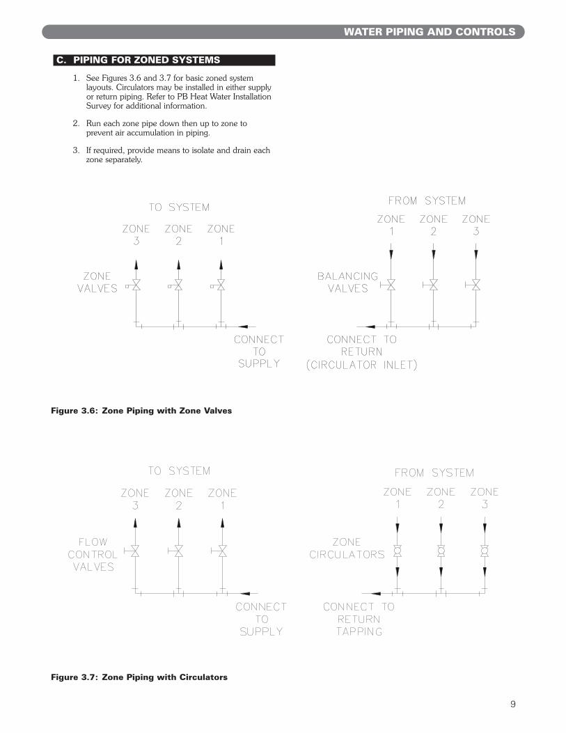
C. PIPING FOR ZONED SYSTEMS
1. See Figures 3.6 and 3.7 for basic zoned systemlayouts. Circulators may be installed in either supplyor return piping. Refer to PB Heat Water InstallationSurvey for additional information.
2. Run each zone pipe down then up to zone toprevent air accumulation in piping.
3. If required, provide means to isolate and drain eachzone separately.
Figure 3.6: Zone Piping with Zone Valves
Figure 3.7: Zone Piping with Circulators
WATER PIPING AND CONTROLS

10
D. EXPANSION TANK
1. Consult the tank manufacturer’s instructions forspecific information relating to tank installation. Sizethe expansion tank for the required system volumeand capacity. See Table 11.1 for boiler’s watercontent.
2. Expansion tanks are available with built-in fill valvesand check valves for reducing supply water pressureand maintaining minimum system pressure. Checkthe design features of the tank and provide valves asnecessary.
Refer to Figure 3.2 for typical expansion tank piping.
E. INDIRECT-FIRED WATER HEATERBoiler may be used as heat source for indirect-firedwater heater. Refer to Figure 3.8 for typical piping.Follow the instructions provided by the water heatermanufacturer. Pipe the water heater as if a separatespace heating zone.
F. FREEZE PROTECTIONFor new or existing systems that must be freeze-protected:
1. Glycol for hydronic applications is speciallyformulated with inhibitors which prevent the glycolfrom attacking metallic system components. Makecertain that the system fluid is checked for thecorrect glycol concentration and inhibitor level.
2. Antifreeze solutions expand more than water. Forexample, a 50% by volume solution expands 4.8%in volume for a temperature increase from 32°F(0°C) to 180°F (82°C), while water expands 3% withthe same temperature rise. Allowance must be madefor this expansion in system design.
3. For more information, consult the PB Heat WaterInstallation Survey and the antifreeze manufacturer.
Figure 3.8: Typical Piping with Indirect-Fired Water Heater
WATER PIPING AND CONTROLS
Use only inhibited propylene glycol solutions of up to50% by volume with water. Ethylene glycol is toxicand can attack gaskets and seals used in hydronicsystems.
WARNING

11
A. DRAFT HOOD
1. The boiler is equipped with a draft hood designed to:
a. provide for the ready escape of flue gases fromthe boiler in the event of no draft.
b. prevent a backdraft from entering the boiler.
c. control stack draft during operation.
The draft hood must be installed without alteration.Make certain there are no obstructions to airflow tothe relief opening.
2. Position draft hood with 1" (25 mm) diameter hole inconical portion of draft hood (for vent safety shutoffswitch) towards front right corner of boiler. Secure toflue collector with sheet metal screws. See Figure 4.1.
3. The boiler is equipped with a vent safety shutoffswitch. The switch is shipped in a cloth bag attachedto the harness on the exterior of the boiler. Attachswitch to holes in the conical portion of the drafthood using the screws provided in bag. SeeFigure 4.1.
Vent safety shutoff switch wiring harness must extendto vent safety shutoff switch without excessive slack.To adjust harness length, squeeze strain relief bushingto release from jacket. Adjust harness to properlength. Reinsert strain relief bushing.
4. VENTING
Figure 4.2: Venting Multiple Appliances
VENTING
Figure 4.1: Draft Hood and Vent Safety ShutoffSwitch Installation

12
Figure 4.3: Venting with Vent Damper in Vertical Position
B. AUTOMATIC VENT DAMPERINSTALLATION – GENERAL
1. Do not use one vent damper to control two or moreheating appliances. See Figure 4.2.
2. Follow these and the installation instructions includedwith the vent damper. Observe the cautions andwarnings that accompany all instructions.
3. Provide minimum 6 inch (152 mm) clearancebetween automatic vent damper and combustibleconstruction. Increase clearance if required by ventdamper manufacturer’s instructions. Provideadequate space for vent damper access and service.
4. The automatic vent damper can be mounted directlyonto the draft hood outlet or in vent piping close tothe boiler.
See Figure 4.3 for installation with vent dampermounted in vertical position. See Figure 4.4 forinstallation with vent damper mounted in horizontalposition. Mount the unit to avoid excessive heat onthe operator or condensation drips into the operator.
a. Orient the vent damper operator to facilitateconnection of the vent damper harness toknockout on right side of boiler. See Figure 6.1.
b. Orient vent damper direction arrow in directionof vent gas flow. Direction arrow must be visiblefrom front of boiler.
C. VENT PIPING AND CHIMNEY
1. Install vent piping in accordance with current editionof National Fuel Gas Code, ANSI Z223.1/NFPA 54under “Venting of Equipment”, or applicableprovisions of the local building codes, or CAN/CGAB149 Installation Codes.
2. Inspect the existing chimney and lining for structuralsoundness, corrosion and perforations. Repair asnecessary.
3. Install vent pipe to slope upward at least 1/4" perlineal foot (21 mm per meter) between the drafthood outlet and the chimney.
4. Before connection of joints, inspect the vent pipeinterior for foreign objects such as tools, equipment,rags, etc. and remove if present.
5. Insert vent pipe into but not beyond the inside wallof the chimney flue.
6. Do not connect vent connectors serving appliancesvented by natural draft into any portion ofmechanical draft systems operating under positivepressure.
7. Support horizontal portions of the venting system toprevent sagging by use of metal strapping orequivalent means. Locate supports at no more thanfour (4) foot (122 cm) intervals, or in accordance withvent system manufacturer’s installation instructions.
VENTING

13
D. BOILER REMOVAL FROM COMMONVENTING SYSTEM
At the time of removal of an existing boiler, follow thesesteps with each appliance remaining connected to thecommon venting system placed in operation, while theother appliances remaining connected to the commonventing system are not in operation:
a. Seal any unused openings in the common ventingsystem.
b. Visually inspect the venting system for proper sizeand horizontal pitch and determine there is noblockage or restriction, leakage, corrosion and otherdeficiencies which could cause an unsafe condition.
c. Insofar as is practical, close all building doors andwindows and all doors between the space in whichthe appliances remaining connected to the commonventing system are located and other spaces of thebuilding. Turn on any clothes dryers and anyappliance not connected to common venting system.Turn on any exhaust fans, such as range hoods andbathroom exhausts, so they will operate at maximumspeed. Do not operate a summer exhaust fan. Closefireplace dampers.
d. Place in operation the appliance being inspected.Follow the lighting instructions. Adjust thermostat soappliance will operate continuously.
e. Test for spillage at the draft hood relief opening after5 minutes of main burner operation. Use the flameof a match or candle, or smoke from a cigarette,cigar, or pipe.
f. After it has been determined that each applianceremaining connected to the common venting systemproperly vents when tested as outlined above, returndoors, windows, exhaust fans, fireplace dampers andany other gas-burning appliance to their previousconditions of use.
g. Any improper operation of the common ventingsystem should be corrected so that the installationconforms with the National Fuel Gas Code, ANSIZ223.1/NFPA 54 or CAN/CGA B149 InstallationCodes. When resizing any portion of the commonventing system, the common venting system shouldbe resized to approach minimum size as determinedusing the appropriate tables located in the chapter“Sizing of Category I Venting Systems,” of theNational Fuel Gas Code, ANSI Z223.1/NFPA 54 orCAN/CGA B149 Installation codes.
VENTING
Figure 4.4: Venting with Vent Damper in Horizontal Position

14
1. Size and install the gas supply piping to provide asupply of gas sufficient to meet the maximumdemand of all appliances without undue loss ofpressure between the meter and the boiler.Maximum permissible gas supply pressure to theboiler is 13.5 inches (3.4 kPa) water column.
2. Determine the volume of gas to be provided to theboiler. Obtain this value by dividing the Btu per hour(Watts) rating (on the boiler rating plate) by theheating value of the gas in Btu per cubic feet (Joulesper cubic meter). Obtain the heating value of the gasfrom the gas supplier. As an alternative, use Table5.1 to obtain the volume of gas to be provided tothe boiler.
3. Table 5.2 shows the maximum flow capacity ofseveral pipe sizes based on 0.3" w.c. (.08 kPa) ofwater pressure drop. These values are based on aspecific gravity of 0.60. Apply the factors indicated inTable 5.3 for gas with specific gravity other than 0.60to obtain corrected capacities.
4. Connection of boiler to the gas piping system maybe made on the left side or top of the boiler. SeeFigure 11.1 for jacket opening locations.
5. Install a sediment trap. See Figure 5.1. Locate a teein the drop pipe at same elevation as the gas inletconnection to the boiler. Extend the drop pipe to apipe cap. As an alternate, the sediment trap may belocated in the boiler vestibule. See Figure 5.2.
6. Install a ground joint union ahead of the gas controlassembly to permit servicing of the control. Somelocal codes require an additional equipment shutoffvalve when using the combination gas controls. Ifyour code requires such a valve, a suggestedlocation is shown in Figure 5.1 or 5.2.
7. Check piping for leaks. Use an approved gasdetector, a non-corrosive leak detection fluid or otherleak detection method. If leaks are found, turn off allgas flow and repair as necessary.
5. GAS PIPING
Figure 5.1: Gas Connection to Boiler - External
When checking for leaks, do not use matches,candles, open flames or other methods that provide asource of ignition. This can ignite a gas leak,resulting in fire or explosion.
WARNING
Use a pipe joint sealing compound that is resistant tothe action of liquefied petroleum gas. A non-resistantcompound may lose sealing ability in the presence ofthis gas, resulting in a gas leak and fire or explosionpotential.
WARNING
GAS PIPING
102030405060
PipeLength
Feet
278190152130115105
3/4"Pipe
520350285245215195
1"Pipe
1,050730590500440400
1-1/4"Pipe
1,6001,100890760670610
1-1/2"Pipe
Capacity of Schedule 40 pipe [cu. ft. per hour (cu. m perhour)] with pressure drop of 0.3 in. (75 Pa) and specific gravityof 0.60. No allowance for an ordinary number of fittings isrequired.
Table 5.1: Input
Model
Natural Gas LP Gas (Cubic Feet
Per Hour)
(Cubic Meter
Per Hour)
(Cubic Feet
Per Hour)
(Cubic Meter
Per Hour)
GM-05 228 6.5 91 2.6
GM-06 285 8.1 114 3.2
GM-07 342 9.7 137 3.9
GM-08 399 11.3 160 4.5
Natural gas based on 1000 Btu/Cubic Foot (37,300 kJ/m³).LP gas based on 2,500 Btu/Cubic Foot (93,145 kJ/m³).
Table 5.2: Capacity of Schedule 40 Pipe
7.85.44.33.73.33.0
159.98.16.96.15.5
302117141211
453125221917
m³ m³ m³ m³ft.³ ft.³ ft.³ ft.³
Table 5.3: Maximum Capacity Correction FactorsSpecific Gravity other than 0.60
Specific Gravity 0.50 0.55 0.60 0.65 0.70 0.75Correction Factor 1.10 1.04 1.00 0.96 0.93 0.90Specific Gravity 0.80 0.85 0.90 1.00 1.10 1.20
Correction Factor 0.87 0.84 0.82 0.78 0.74 0.71Specific Gravity 1.30 1.40 1.50 1.60 1.70 1.80
Correction Factor 0.68 0.66 0.63 0.61 0.59 0.58

15
GAS PIPING
8. Disconnect the boiler and its individual shut-off valvefrom the gas supply piping system during anypressure testing of that system at test pressure inexcess of 1/2 psig (3.5 kPa).
Isolate the boiler from the gas supply piping systemby closing its individual service valve during anypressure testing of the gas supply piping system attest pressure equal to or less than 1/2 psig (3.5 kPa).
9. Minimum permissible natural gas supply pressureInches Water Column (kPa)]:
Minimum permissible LP gas supply pressure is 11.0" w.c. (2.7 kPa).
10. Maximum permissible supply pressure to the boiler[Inches Water Column (kPa)]:
All models 13.5" (3.4 kPa)
Do not subject the gas valve to more than 1/2 psipressure (3.5 kPa). Doing so may damage the valve.
CAUTION
Figure 5.2: Gas Connection to Boiler - Internal
Standing Pilot
IntermittentIgnition
4.8
4.5
GM-05
5.5
4.5
GM-06 GM-07
----
4.9
GM-08
In. In. In.----
4.6
In.1.2
1.1
kPa1.4
1.1
kPa----
1.1
kPa----
1.2
kPa

16
A. WIRING
1. See Figure 6.1 for location of wiring and controls.use Figures 6.4 - 6.6 to connect the boiler to apower supply and then connect components to theboiler.
2. Connect the boiler to a separate, permanently liveelectrical supply line with a fused switch.
3. Connect the vent damper harness to the polarizedconnector in the boiler vestibule as shown in Figure 6.1.
B. CIRCULATOR/ZONE VALVE WIRING
1. A zone control is required to operate circulator(s)when using a low voltage thermostat.
2. Taco Zoning circulator(s) can be used instead ofmounting separate circulator relay(s) (Figure 6.2).
3. Figure 6.8 shows typical wiring for one or morecirculators.
4. Figure 6.9 shows typical wiring for zone valves.
C. LOW WATER CUTOFF
Wire low water cutoff to turn off power to boiler. SeeFigure 6.3 for Hydrolevel 550 low water cutoff. Refer tomanufacturer’s instructions for other low water cutoffs.
ELECTRICAL
6. ELECTRICAL
This unit when installed must be electrically grounded in accordance with the requirements of the authorityhaving jurisdiction or, in the absence of such requirements, with the current edition of the National ElectricalCode, ANSI/NFPA 70 or the Canadian Electrical Code Part I, CSA C22.1, Electrical Code.
NOTICE
Figure 6.1: Wiring Details
Do not power zone valves directly from the boilertransformer. Doing so will greatly reduce the life ofthe transformer. Use a separate transformer sized tohandle the total of all zone valve electrical loads.
NOTICE

17
Figure 6.2: Taco Zoning Circulator Wiring
ELECTRICAL
Figure 6.3: Hydrolevel 550 Low Water Cutoff Wiring
18
ELECTRICAL
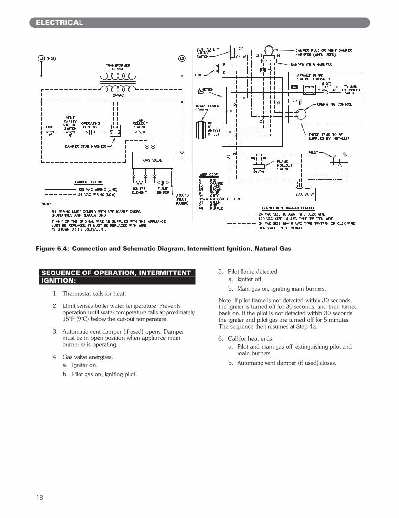
SEQUENCE OF OPERATION, INTERMITTENTIGNITION:
1. Thermostat calls for heat.
2. Limit senses boiler water temperature. Preventsoperation until water temperature falls approximately15°F (9°C) below the cut-out temperature.
3. Automatic vent damper (if used) opens. Dampermust be in open position when appliance mainburner(s) is operating.
4. Gas valve energizes.a. Igniter on.
b. Pilot gas on, igniting pilot.
5. Pilot flame detected.a. Igniter off.
b. Main gas on, igniting main burners.
Note: If pilot flame is not detected within 30 seconds,the igniter is turned off for 30 seconds, and then turnedback on. If the pilot is not detected within 30 seconds,the igniter and pilot gas are turned off for 5 minutes.The sequence then resumes at Step 4a.
6. Call for heat ends.a. Pilot and main gas off, extinguishing pilot and
main burners.
b. Automatic vent damper (if used) closes.
Figure 6.4: Connection and Schematic Diagram, Intermittent Ignition, Natural Gas

19
SEQUENCE OF OPERATION, INTERMITTENTIGNITION:
1. Thermostat calls for heat.
2. Limit senses boiler water temperature. Preventsoperation until water temperature falls approximately15°F (9°C) below the cut-out temperature.
3. Automatic vent damper (if used) opens. Dampermust be in open position when appliance mainburner(s) is operating.
4. Gas valve energizes.a. Igniter on.
b. Pilot gas on, igniting pilot.
5. Pilot flame detected.a. Igniter off.
b. Main gas on, igniting main burners.
Note: If pilot flame is not detected within 30 seconds,the igniter is turned off for 30 seconds, and then turnedback on. If the pilot is not detected within 30 seconds,the igniter and pilot gas are turned off for 5 minutes.The sequence then resumes at Step 4a.
6. Call for heat ends.a. Pilot and main gas off, extinguishing pilot and
main burners.
b. Automatic vent damper (if used) closes.
Figure 6.5: Connection and Schematic Diagram, Intermittent Ignition, LP Gas
ELECTRICAL

20
ELECTRICAL
Figure 6.6: Connection and Schematic Diagram, Standing Pilot
SEQUENCE OF OPERATION, STANDINGPILOT:
1. Thermostat calls for heat.
2. Limit senses boiler water temperature. Preventsoperation until water temperature falls approximately15°F (9°C) below the cut-out temperature.
3. Automatic vent damper opens.
4. Gas valve energizes.
5. Pilot flame detected by thermocouple. Main gas on,igniting main burners.
Note: If pilot flame is not detected, main and pilotgas are automatically turned off. Pilot must bemanually relit. See Figure 8.7 for LightingInstructions.
6. Call for heat ends.a. Main gas off, extinguishing main burners.
b. Automatic vent damper closes.

21
ELECTRICAL
Figure 6.7: Intermittent Ignition System Operating Sequence

22
ELECTRICAL
Figure 6.8: Circulator Wiring
Figure 6.9: Zone Valve Wiring

23
A. GENERALThis section is in regard to requirements of the ASMECSD-1 Code, Controls and Safety Devices forAutomatically Fired Boilers, which may be in effect inyour area. Any omissions or discrepancies that may existbetween these instructions and the CSD-1 code itself,the code itself takes precedence. The CSD-1 Code maybe ordered by calling 1-800-THE-ASME.
B. CSD PART CF REQUIREMENTSThe Series GM is CSA certified to ANSI Z21.13 (CSA4.9) and as such meets all CSD-1 Part CF requirementsfor combustion side controls for units under 400,000btuh (117 kW) input. No other combustion side controlsare required to meet CSD-1.
C. CSD PART CW REQUIREMENTSCSD-1 requires the following waterside controls to beinstalled with the boiler:
1. Manual reset low water cut-off (LWCO), such asHydrolevel 550SV Probe (29028)
2. Manual reset high limit, such as HoneywellL4006E1117 (50536).
Install these controls in the supply piping. Figures 7.1-7.3 show typical piping using a probe style low watercut-off.
See CSD-1 code for requirements when using a floattype low water cut-off.
No valves are allowed between these controls and theboiler supply connection.
Low water cut-off must be positioned higher than thetop of the boiler. See Figure 7.4 for wiring details. Followall instructions furnished by the control manufacturers.
D. CSD MODULAR AND MULTIPLE BOILERREQUIREMENTS1. Modular Boilers
a. CSD-1 requires a manual reset low water cut-offand manual reset high limit to control themodular boiler system. The individual boilermodules are not required to have a low watercut-off or manual reset high limit.
b. To be considered a modular boiler system, theindividual boiler modules are not allowed to beisolated from the main headers and controls withstop valves.
2. Multiple BoilersCSD-1 requires a manual reset low water cut-off andmanual reset high limit on each individual boiler.
For more information on modular and multiple boilersystems, see the Flex-Heat manual or contact PB Heat.
CSD CODE REQUIREMENTS
7. CSD CODE REQUIREMENTS
Figure 7.1: CSD Piping, Using Cross Fitting
Figure 7.2: CSD Piping, Vertical Using Tee’s
Figure 7.3: CSD Piping, Horizontal
(51 MM)
(102 MM)
(51 MM)
(102 MM)
(51 MM)
(102 MM)

24
E. CSD PART CE ELECTRICALREQUIRMENTSNote the following electrical requirements per CSD-1Section CE-110(a):
“A disconnecting means capable of being locked inthe open position shall be installed at an accessiblelocation at the boiler so that the boiler can bedisconnected from all sources of potential. Thisdisconnecting means shall be an integral part of theboiler or adjacent to it.”
“A manually operated remote shutdown switch orcircuit breaker shall be located just outside the boilerroom door and marked for easy identification.Consideration should be given to the type andlocation of the switch to safeguard againsttampering. If the boiler room door is on the buildingexterior, the switch should be located just inside thedoor. If there is more than one door to the boilerroom, there should be a switch located at eachdoor.”
“The emergency shutdown switch or circuit breakermust disconnect all power to the burner controls.”
CSD CODE REQUIREMENTS
Figure 7.4: CSD Low Water Cut-Off/Limit Wiring

25
START-UP PROCEDURES
8. START-UP PROCEDURES
A. COMPLETING THE INSTALLATION
1. Confirm that all water, gas and electricity areturned off.
2. Inspect the boiler combustion chamber for foreignobjects and remove if present.
3. Check physical condition of burners and pilot. Makecertain that there are no unusual bends orperforations in the burners or pilot. Replacecomponents if necessary.
4. Verify that water piping, venting, gas piping andelectrical wiring and components are installedproperly. Refer back to previous sections of theseinstructions as well as equipment manufacturer’sinstructions as necessary.
5. Fill the boiler and system with water, making certainto vent all air from all points in the system. To checkwater level in the system, open and close each ventin the system. Water should exit from each vent whenit is opened.
6. The pressure reducing valve on the fill line willtypically allow the system to be filled and pressurizedto 12 psi (83 kPa). Consult the valve and expansiontank manufacturer for more specific information.
7. Check joints and fittings throughout the system forleaks. If leaks are found, drain the system and repairas required.
8. Connect a manometer to 1/8 NPT tapping providedon the manifold. See Figures 8.1 and 8.2.
9. Confirm that the gas supply pressure to the boiler isabove the minimum and below the maximum valuesfor the gas being used. See the end of Section 5 forthese values. If a supply pressure check is required,isolate the boiler and gas valve before performing thepressure check. If the supply pressure is too high ortoo low, contact the gas supplier.
10. Turn on electricity and gas to boiler.
11. Light the boiler by following the Lighting/OperatingInstructions label mounted to the jacket panel. Theinitial ignition may require several tries as the pipingis purged of air.
12. Use the sequence descriptions in Figures 6.4, 6.5 and6.6 in Section 6 (Electrical) to follow light-off andshutdown sequences and to assist in diagnosingproblems. If the boiler does not function properly,consult Section 9, Troubleshooting.
13. The gas manifold and control assembly provided with this boiler meet with all criteria regarding safelighting and performance as specified in ANSI Z21.13 (CSA 4.9), Gas-Fired Low-Pressure Steamand Hot Water Boilers. The gas manifold and control assembly are made of gas-tight, completely factoryassembled and installed components of the baseassembly. See Figures 8.1 and 8.2.

26
START-UP PROCEDURES
Figure 8.1: Gas, Valve, Manifold and Burner Assembly, GM-05/06 (Standing Pilot shown, IntermittentIgnition similar)
Figure 8.2: Gas, Valve, Manifold and Burner Assembly, GM-07/08 (Intermittent Ignition)
Figure 8.3: Valve Tapping and Adjustment ScrewLocations, Intermittent Ignition, Natural Gas
Figure 8.4: Valve Tapping and Adjustment ScrewLocations, Standing Pilot or LP Gas

27
START-UP PROCEDURES
Figure 8.5: Operating Instructions, SmartValve Intermittent Ignition (boiler model suffix “SV”)

28
Figure 8.6: Operating Instructions, Spark Intermittent Ignition (boiler model suffix “SPRK”)
HSP VR8204/VR8304 9181R REV.1
FOR YOUR SAFETY READ BEFORE LIGHTING
WARNING: If you do not follow these instructions exactly, a fire or explosion may
result causing property damage, personal injury, or loss of life.
OPERATING INSTRUCTIONS
TO TURN OFF GAS TO APPLIANCE1. Set the thermostat or operating control to lowest setting.
2. Turn off all electric power to the appliance if service is to be performed.
3. If the gas valve is not visible, remove the control
access panel.
4. Turn the gas control knob clockwise to "OFF".
5. Replace control access panel, if applicable.
1. STOP! Read the safety information above on this label.
2. Set the thermostat or operating control to lowest setting.
3. Turn off all electric power to the appliance.
4. This appliance is equipped with an ignition device
which automatically lights the pilot. Do not try to light
the pilot by hand.
5. If the gas valve is not visible, remove control access
panel. 6. If the gas control knob is not in the "OFF" postion,
turn the knob clockwise to "OFF".
7. Wait five (5) minutes to clear out any gas. Then smell
for gas, including near the floor. If you smell gas,
STOP! Follow "B" in the safety information above on
this label. If you don't smell gas, go to the next step.
8. Turn the gas control knob counterclockwise to
"ON".
9. Replace control access panel, if applicable.
10. Turn on all electrical power to the appliance.
11. Set thermostat or operating control to desired setting. 12. If the appliance will not operate, follow the
instructions "To Turn Off Gas To Appliance" and call your service technician or gas supplier.
A. This appliance is equipped with an ignition device
which automatically lights the pilot. Do not try to light the pilot by hand.
B. BEFORE OPERATING smell all around the appliance
area for gas. Be sure to smell next to the floor
because some gas is heavier than air and will settle on the floor.
WHAT TO DO IF YOU SMELL GAS
Do not try to light any appliance Do not touch any electric switch; do not use any phone in your building.
Immediately call your gas supplier from a
neighbor's phone. Follow the gas supplier's
instructions.
If you cannot reach your gas supplier,
call the fire department.
C. Use only your hand to push in or turn the gas control knob. Never use tools. If the knob will not push in or turn by hand, don't try to repair it, call a qualified service technician. Force or attempted repair may result in a fire or explosion.
D. Do not use this appliance if any part has been under water. Immediately call a qualified service technician to inspect the appliance and to replace any part of the control system and any gas control which has been under water.
Gas Control Knob
(shown in "OFF"
position)
START-UP PROCEDURES

29
START-UP PROCEDURES
Figure 8.7: Lighting Instructions
H24V VR8200/VR8300 9177R
If you cannot reach your gas supplier, call the fire department.
C. Use only your hand to push in or turn the gas control knob. Never use tools. If the knob will not push in or turn by hand, don't try to repair it, call a qualified service technician. Force or attempted repair may result in a fire or explosion.
D. Do not use this appliance if any part has been under water. Immediately call a qualified service technician to inspect the appliance and to replace any part of the control system and any gas control which has been under water.
WARNING: If you do not follow these instructions exactly, a fire or explosion may
result causing property damage, personal injury, or loss of life.
FOR YOUR SAFETY READ BEFORE LIGHTING
LIGHTING INSTRUCTIONS
1. STOP! Read the safety information above on this label.
2. Set the thermostat to lowest setting.
3. Turn off all electric power to the appliance.
4. If the gas valve is not visible, remove control access
panel.
5. If the gas control knob is not in the "OFF" position, turn the knob clockwise to "OFF".
Gas Control Knob
(shown in "OFF"
position)Red Reset Button
6. Wait five (5) minutes to clear out any gas. Then smell
for gas, including near the floor. If you smell gas,
STOP! Follow "B" in the safety information above on
this label. If you don't smell gas, go to the next step.
7. Remove the pilot access panel, if supplied, located
below and behind the gas valve directly above burner
tubes.
TO TURN OFF GAS TO APPLIANCE
8. Find pilot - follow metal tube from gas valve. The pilot is between two burner tubes
Pilot Burner
9. Turn the gas control knob counterclockwise to
"PILOT".
10. Push in red reset button all the way and hold in.
Immediately light the pilot with a match. Continue to
hold the reset button in for about one (1) minute after
the pilot is lit. Release button and it will pop back up.
Pilot should remain lit. If it goes out, repeat steps 5
through 10.
If button does not pop up when released, stop and
immediately call your service technician or gas
supplier.
If the pilot will not stay lit after several tries, turn the
gas control knob to "OFF" and call your service
technician or gas supplier.
11. Replace pilot access panel, if applicable.
12. Turn gas control knob counterclockwise to "ON".
13. Replace control access panel, if applicable.
14. Turn on all electric power to the appliance.
15. Set thermostat to desired setting.
1. Set the thermostat to lowest setting.
2. Turn off all electric power to the appliance if service is to be performed.
3. If the gas valve is not visible, remove the control access panel.
4. Turn the gas control knob clockwise to "OFF".
5. Replace control access panel, if applicable.
A. This appliance has a pilot which must be lighted by hand. When lighting the pilot, follow these instructions exactly.
B. BEFORE LIGHTING smell all around the appliance area for gas. Be sure to smell next to the floor because some gas is heavier than air and will settle on the floor.
WHAT TO DO IF YOU SMELL GAS Do not try to light any appliance Do not touch any electric switch; do not use any phone in your building Immediately call your gas supplier from a neighbor's phone. Follow the gas supplier's instruction.

30
B. CONTROL DESCRIPTIONSSee Figure 8.8 for locations of these devices.
1. FLAME ROLLOUT SAFETY SHUTOFF SWITCH –A thermally activated switch located above theburners on the inner front jacket panel. The flamerollout safety shutoff switch will sense excessivetemperature caused by continued flame rollout andshut down main burner gas. This is a non-recyclingswitch that must be replaced once activated.
2. VENT SAFETY SHUTOFF SWITCH – A thermallyactivated, manually resetable switch located on thedraft hood. If venting system becomes partially ortotally blocked, the vent safety shutoff switch willsense excessive temperature caused by flue productsexiting the draft hood relief opening and shut downmain burner gas.
3. LIMIT – A thermally activated, manually adjustableswitch located in the upper right side of boilervestibule. The limit senses supply water temperatureand will shut down main burner gas if the supplywater exceeds the preset temperature limit. This is arecycling switch that will automatically reset whenthe supply water falls below the preset temperature.
4. LOW WATER CUT-OFF (FOR GRAVITY SYSTEMSOR HOT WATER BOILERS INSTALLED ABOVERADIATION LEVEL) – A level-sensing device (floator probe) located in supply piping near the boiler. Ifwater level in the system drops below the control’sposition, it will shut down main burner gas. Thecontrol will automatically reset once the water levelrises above its position.
C. ADJUSTMENT OF GAS PRESSUREREGULATOR
1. Using the manometer setup installed in part 8A, setmanifold pressure.
2. To adjust gas pressure, turn adjusting screw of gaspressure regulator counterclockwise to decreasepressure, clockwise to increase pressure. Refer toFigure 8.3 and 8.4 for location of gas pressureregulator. Replace the cap screw when adjustment iscomplete.
3. In no case should the final manifold pressure varymore than ±0.3 inches (±75 Pa) water column fromthe above specified pressures. Any necessary majorchanges in the flow should be made by changing thesize of the burner orifice spuds.
4. When adjustment is complete, turn off boiler, gasflow and electricity to boiler. Remove manometerconnection from valve and plug tapping with plugprovided. Turn utilities back on and resumecheckout.
D. CHECKING BURNER INPUT
1. Refer to rating label mounted on the jacket top panelto obtain the rated BTU (kW) per hour input. In nocase shall the input to the boiler exceed the valueshown on the rating label.
2. Check input by use of the following formula [PBHeat suggests reading meter for 2 Cu. Ft. (.05 Cu.Meter)]:
BTU/Hr. Input=3600 x F x HT
3600 – Seconds per hourF – Cubic Feet of Gas Registered on MeterH – Heat Value of Gas in BTU/Cubic FeetT – Time in Seconds the Meter is Read
(Metric) Determine the input by multiplying “F” – Meter Reading (Cubic Meters of Gas) times“H” – Heating Value of Gas (Joules per CubicMeter). Divide by “T” – the time in seconds of themeter reading.
Rate, Watts=F x HT
3. As an alternative, use Table 8.1. Use the heatingvalue provided by gas supplier. Use a stopwatch torecord the time it takes for 2 cubic feet (.05 cubicmeter) of gas to pass through the meter. Read acrossand down to determine rate.
START-UP PROCEDURES
Figure 8.8: Control Locations

31
Burner inputs in Btu/hr for various meter timings andheat values. (Table based on 2 cubic feet of gas throughmeter).
(Metric) Burner inputs in Watts for various meter timingsand heat values. (Table based on .05 cubic meters of gasthrough meter).
E. CHECK-OUT PROCEDURE
1. After starting the boiler, be certain all controls areworking properly. Check to be sure that the limit willshut off the boiler in the event of excessive watertemperature. This can be done by lowering the limitsetting until the main burners shut down. Whenproper limit function is confirmed, return the dial toits previous setting.
2. To check operation of the ignition system safetyshut-off features:a. Standing Pilot:
i) Turn the gas control knob counterclockwiseto “PILOT”. The main burner should go outand the pilot should remain lit.
ii) Extinguish the pilot flame. Pilot gas flowshould stop within 2-1/2 minutes. Completeshutdown is proven since the safety shut-offvalve has stopped main and pilot gas flow.
iii) Reset the boiler by following LightingInstructions.
iv) Observe boiler operation through onecomplete cycle.
b. Spark Intermittent Ignition System:
i) Turn gas supply off.
ii) Set thermostat or controller above roomtemperature to call for heat. Watch forigniter glow at pilot burner.
iiia) SmartValve Intermittent Ignition - Igniter willcontinue to glow for 30 seconds, de-energizefor 30 seconds, then re-energize and glowfor another 30 seconds. It will then de-energize for 5 minutes before restarting thesequence.
iiib) Spark Ignition - Igniter will continue to sparkfor 90 seconds and then de-energize for 5minutes. It will then restart the sequence.
iv) Turn gas supply on.
v) Reset the boiler and control by followingOperating Instructions.
vi) Observe boiler operation through onecomplete cycle.
3. Low Water Cut-Off (if used) – Consult themanufacturer’s instructions for the low water cut-offoperational check procedure.
4. Check the system to make sure there are no leaks oroverfilling problems which might cause excessivemake-up water to be added. Make-up water causesliming in the boiler and brings in oxygen. Oxygencan cause severe damage to the boiler thoughoxygen corrosion pitting.
5. Check the expansion tank and automatic fill valve (ifused) to confirm that they are operating correctly. Ifeither of these components causes high pressure inthe system, the boiler relief valve will weep or open,allowing fresh water to enter the system.
6. Do not allow the system controls to subject the boilerto excessively low water temperatures, which wouldcause condensation of flue gases and corrosion ofthe boiler. Operate the boiler at a temperature above130°F (54°C). Adjust the boiler limit as required tomaintain boiler temperature above this level.
7. Check the general condition of the system includingpiping support, joints, etc. Check cleanliness of theradiators, baseboard units and/or convectors. Cleanthem to the extent possible. If radiators do not heatevenly, vent any remaining air from them.
8. Review operation and User’s Information Manualwith end-user.
9. Complete the Warranty Card and submit it to PBHeat.
10. Hang the Installation, Operation and MaintenanceManual and User’s Information Manual in anaccessible position near the boiler.
START-UP PROCEDURES
Table 8.1a: Meter Conversion – Natural Gas
480,000360,000288,000240,000205,714
1520253035
492,000369,000295,200246,000210,857
504,000378,000302,400252,000216,000
Heat Value of Gas(Btu/cubic foot)
1,000 1,025 1,050
Time thatmeter is
read (sec)
124,33393,25074,60062,16753,286
1520253035
127,33395,50076,40063,66754,571
130,33397,75078,20065,16755,857
Heat Value of Gas(kJ/cubic meter)
37,300 38,200 39,100
Time thatmeter is
read (sec)
Table 8.1b: Meter Conversion – Natural Gas
32
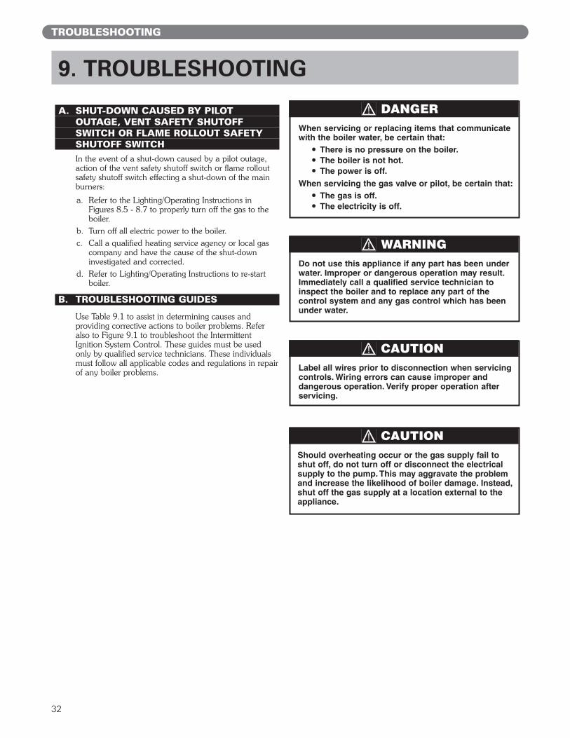
A. SHUT-DOWN CAUSED BY PILOT OUTAGE, VENT SAFETY SHUTOFFSWITCH OR FLAME ROLLOUT SAFETY SHUTOFF SWITCHIn the event of a shut-down caused by a pilot outage,action of the vent safety shutoff switch or flame rolloutsafety shutoff switch effecting a shut-down of the mainburners:
a. Refer to the Lighting/Operating Instructions inFigures 8.5 - 8.7 to properly turn off the gas to theboiler.
b. Turn off all electric power to the boiler.c. Call a qualified heating service agency or local gas
company and have the cause of the shut-downinvestigated and corrected.
d. Refer to Lighting/Operating Instructions to re-startboiler.
B. TROUBLESHOOTING GUIDES
Use Table 9.1 to assist in determining causes andproviding corrective actions to boiler problems. Referalso to Figure 9.1 to troubleshoot the IntermittentIgnition System Control. These guides must be usedonly by qualified service technicians. These individualsmust follow all applicable codes and regulations in repairof any boiler problems.
TROUBLESHOOTING
9. TROUBLESHOOTING
Should overheating occur or the gas supply fail toshut off, do not turn off or disconnect the electricalsupply to the pump. This may aggravate the problemand increase the likelihood of boiler damage. Instead,shut off the gas supply at a location external to theappliance.
CAUTION
Do not use this appliance if any part has been underwater. Improper or dangerous operation may result.Immediately call a qualified service technician toinspect the boiler and to replace any part of thecontrol system and any gas control which has beenunder water.
WARNING
Label all wires prior to disconnection when servicingcontrols. Wiring errors can cause improper anddangerous operation. Verify proper operation afterservicing.
CAUTION
When servicing or replacing items that communicatewith the boiler water, be certain that:
● There is no pressure on the boiler.● The boiler is not hot.● The power is off.
When servicing the gas valve or pilot, be certain that:● The gas is off.● The electricity is off.
DANGER

33
TROUBLESHOOTING
Table 9.1: Boiler Troubleshooting Guide
PROBLEM POSSIBLE CAUSES CORRECTIVE ACTIONS
1. No power.2. Limit (Aquastat) not working.
3. Flame rollout switch open.4. Blocked vent switch open.5. Gas off at boiler gas valve.
6. Gas off external to boiler.7. Plugged orifice spuds.8. Defective gas valve.
9. Improper wiring.
10. Vent damper malfunctioning.
Burners not functioning. 1. Check line voltage wiring and fuses.2. Check wiring and contacts, relay, temperature
setting. Clean and adjust as necessary.3. Replace switch. Locate cause and correct.4. Reset blocked vent switch. Locate cause and correct.5. Start boiler using Lighting/Operating
Instructions.6. Check any gas valves in the line.7. Check, clean and re-install.8. Use Figure 9.1 to troubleshoot intermittent
ignition gas valve. Replace if necessary.9. Check and correct in accordance with wiring
diagrams in Section 6.10. Refer to vent damper manufacturer’s instructions.
Replace if necessary.
1. Defective gas valve.
2. Short circuit.
Burners will not shutdown.
1. Use Figure 9.1 to troubleshoot intermittentignition gas valve. Replace if necessary.
2. Check and correct wiring.
1. Manifold gas pressure too low.2. Improperly sized/drilled orifice spuds.3. Leaking gas valve.4. Burrs on orifice.5. Low supply gas pressure.6. Excessive downdraft or draft problems in
boiler room.
Flashback or burningat orifice spuds.
1. Adjust to proper pressure.2. Install correct spuds.3. Replace valve.4. Remove burrs.5. Contact gas supplier.6. Check air supply, ventilation and venting system.
1. Insufficient pilot flame.2. Pilot burner/orifice clogged.3. Overfiring.4. Misaligned burners or pilot.5. Draft problem in boiler room.
Delayed ignition. 1. Increase pilot gas flow.2. Clean pilot burner and orifice.3. Reduce rate to input on rating label.4. Realign burners or pilot.5. Check air supply, ventilation and venting
system.
1. Underfiring.2. Limit (Aquastat) set too low.3. Vent pipe too long.4. Inadequate chimney or venting system.
Excessive condensation invent.
1. Increase rate to input on rating label.2. Reset limit (Aquastat) to higher setting.3. Reposition boiler to reduce length.4. Check chimney and venting recommendations.
1. Underfiring.2. Limit set too low.3. Air in system.4. Circulator malfunctioning.5. Circulation system clogged.
6. Incorrect thermostat heat anticipator setting.
Boiler not heatingproperly.
1. Increase rate to input on rating label.2. Reset limit (Aquastat) to higher setting.3. Vent air from all points in system.4. Check circulator, replace if necessary.5. Shut down and cool boiler, drain and flush
system.6. Adjust heat anticipator.
1. Leaks in gas piping or fittings.2. Leaks in gas service line or meter.3. Obstructed chimney.4. Obstructed flueways or vent.5. Undersized chimney or vent, high draft loss
in vent.
6. Draft problem in boiler room.7. Overfiring.8. Vent damper malfunctioning.
Fumes or gas odors 1. Locate and repair or replace.2. Shut down boiler and notify gas provider.3. Check, repair and/or clean chimney.4. Clean flueways or vent and remove obstructions.
5. Check National Fuel Gas Code ANSIZ223.1/NFPA 54 and/or CAN/CGA B149Installation Codes and vent manufacturer’srecommendations.
6. Check air supply, ventilation and venting system.7. Reduce rate to input on rating label.8. Refer to vent damper manufacturer’s instructions.
Replace if necessary.

34
TROUBLESHOOTING
Figure 9.1: SmartValve™ Intermittent Ignition System Troubleshooting Sequence

35
10. MAINTENANCE
WARNING
Product Safety InformationRefractory Ceramic Fiber Product
This appliance contains materials made from refractory ceramic fibers (RCF). Airborne RCF,when inhaled, have been classified by the International Agency for Research on Cancer(IARC), as a possible carcinogen to humans. After the RCF materials have been exposed totemperatures above 1800°F (982°C), they can change into crystalline silica, which has beenclassified by the IARC as carcinogenic to humans. If particles become airborne duringservice or repair, inhalation of these particles may be hazardous to your health.
Avoid Breathing Fiber Particulates and Dust
Suppliers of RCF recommend the following precautions be taken when handling thesematerials:
Precautionary Measures:Provide adequate ventilation.Wear a NIOSH/MSHA approved respirator.Wear long sleeved, loose fitting clothing and gloves to prevent skin contact.Wear eye goggles.Minimize airborne dust prior to handling and removal by water misting the material andavoiding unnecessary disturbance of materials. Wash work clothes separately from others. Rinse washer thoroughly after use.Discard RCF materials by sealing in an airtight plastic bag.
First Aid Procedures:Inhalation: If breathing difficulty or irritation occurs, move to a location with fresh clean air.Seek immediate medical attention if symptoms persist.Skin Contact: Wash affected area gently with a mild soap and warm water. Seek immediatemedical attention if irritation persists.Eye Contact: Flush eyes with water for 15 minutes while holding eyelids apart. Do not rubeyes. Seek immediate medical attention if irritation persists.Ingestion: Drink 1 to 2 glasses of water. Do not induce vomiting. Seek immediate medicalattention.
MAINTENANCE

36
A. GENERAL
1. Disconnect this boiler from the gas supply pipingduring any pressure testing of the gas system.
2. Check pipes adjacent to cold walls or in unheatedspaces. Insulate and tape them if necessary to besure they can’t freeze up. Keeping the water movingat all times will reduce the likelihood of freezing. SeeSection 3 for antifreeze instructions.
3. If there is considerable foreign matter in the boilerwater, the boiler should be shut down and allowed tocool, then drained and thoroughly flushed out. Usethe drain valve at the bottom of the returnconnection to drain the boiler. Pipe the drain cock toa suitable drain or containment device if antifreeze isused. Flush the system to remove remaining matter.If there is evidence that hard scale has formed on theinternal surfaces, the boiler should be cleaned bychemical means as prescribed by a qualified watertreatment specialist.
4. There must not be signs of continuous wetness at thechimney. If signs of continuous wetness areobserved, a qualified service agency must beconsulted to modify the vent configuration to preventthe formation of condensate.
B. DAILY (WITH BOILER IN USE)Daily boiler observation can be performed by the owner.If any potential problems are found, a qualified installeror service technician/agency must be notified.
1. Remove any combustible materials, gasoline andother flammable liquids and substances that generateflammable vapors from the area where the boiler iscontained. Make certain that the boiler area hasample air for combustion and ventilation and thatthere are no obstructions to the free flow of air toand from the boiler.
2. Observe general boiler conditions (unusual noises,vibrations, etc.)
3. Observe operating temperature and pressure on thecombination gauge located on the left side of theboiler. Boiler pressure should never be higher than 5 psi (34 kPa) below the rating shown on the safetyrelief valve [25 psig (172 kPa) maximum for a 30psig (207 kPa) rating, 45 psig (310 kPa) maximumfor a 50 psig (345 kPa) rating]. The valve rating canbe found on the top of the safety relief valve (seeFigure 3.1 for location of the safety relief valve). Boiler temperature should never be higher than250°F (121°C).
4. Check for water leaks in boiler and system piping.
5. Smell around the appliance area for gas. If you smellgas, follow the procedure listed in theLighting/Operating Instructions in Section 8.
C. WEEKLY (WITH BOILER IN USE)
1. Flush float-type low-water cut-off (if used) to removesediment from the float bowl as stated in themanufacturer’s instructions.
D. MONTHLY (WITH BOILER IN USE)
1. Check boiler room floor drains for properfunctioning.
2. Check function of the safety relief valve (monthlyunless specified otherwise by manufacturer) byperforming the following test:a. Check valve piping to determine that it is
properly installed and supported.
b. Check boiler operating temperature and pressure.
c. Lift the try lever on the safety relief valve to thefull open position and hold it for at least fiveseconds or until clean water is discharged.
d. Release the try lever and allow the valve to close.If the valve leaks, operate the lever two or threetimes to clear the valve seat of foreign matter. Itmay take some time to determine if the valve hasshut completely.
e. If the valve continues to leak, it must be replacedbefore the boiler is returned to operation.
f. Check that operating pressure and temperaturehave returned to normal.
g. Check again to confirm that valve has closedcompletely and is not leaking.
3. Test low-water cut-off (if used) as described by themanufacturer.
4. Test limit as described in Section 8E, “Check-OutProcedure.”
5. Test function of gas safety shut-off features asdescribed by gas valve and ignition controlmanufacturer.
6. Cycle the boiler at least once and check operation ofthe vent damper.
MAINTENANCE

37
MAINTENANCE
E. ANNUALLY (BEFORE START OF HEATINGSEASON)
1. Check flueways and burners for cleanliness and cleanif necessary. Use the following procedure if cleaningis required:
a. Refer to the Lighting/Operating Instructions inFigures 8.5 - 8.7 to properly turn off the gas tothe boiler.
b. Turn off all electrical power to the boiler.
c. Remove burners and brush gas outlet portslightly using a soft bristle brush.
d. Remove the vent pipe, automatic vent damper (ifused), draft hood, top jacket panels, flue collectorand flue baffles.
e. Brush flueways with wire brush.
f. To the extent possible, inspect inside of vent pipeand vent damper for obstructions in flow or ventdamper movement. Remove or replace asnecessary.
g. Re-install baffles. When replacing the fluecollector, be certain that the blanket seal betweenthe flue collector and top section makes a tightseal to prevent leakage of the products ofcombustion.
h. Re-install the top of the jacket, draft hood, ventdamper (if used) and vent pipe.
i. Connect blocked vent switch wiring harness toblocked vent switch.
k. Re-install burners.
2. Inspect entire venting system for corrosion, supportand joint integrity. Repair as necessary.
3. Check the pilot and main burner flame. See Figures10.1 and 10.2. The pilot should provide a steadyflame enveloping 3/8" to 1/2" (10 mm to 13 mm) ofthe flame sensor. If required, adjust the pilot as statedin the gas valve manufacturer’s instructions. Themain burner flame inner cone should beapproximately 1-1/2" (40 mm) high and should havea very sharp, blue color characteristic.
4. Systems with antifreeze. Check for correctconcentration and inhibitor level.
When servicing or replacing components, beabsolutely certain that the following conditions aremet:
● Water, gas and electricity are off.● The boiler is at room temperature.● There is no pressure in the boiler.
DANGER
Figure 10.1: Standing Pilot and Main Burner Flame
Figure 10.2: Intermittent Pilot and Main BurnerFlame

38
11. BOILER DIMENSIONS & RATINGS
Figure 11.1: Boiler Views
Table 11.2: Series GM Boiler Ratings
1 Output is Heating Capacity for models with inputs <300 MBH and Gross Output for models with inputs ≥300 MBH. Heating Capacity and Annual FuelUtilization Efficiency (AFUE) ratings are based on U.S. Government test.
2 Output rating and combustion efficiency determined in accordance with ANSI Z21.13, Gas-Fired Low-Pressure Steam and Hot Water Boilers.3 Net I=B=R water ratings based on an allowance of 1.15.4 Consult factory before selecting a boiler for installations having unusual piping and pickup requirements, such as intermittent system operation, extensive piping
systems, etc.
Table 11.1: Series GM Boiler Dimensions
BOILER DIMENSIONS & RATINGS
SERIES GM BOILER DIMENSIONS
BoilerModel
Number
Jacket Width
“A”
Left of Jacket to theCenterline of Vent
“B”
Top of Jacket to Vent Connector
“C”
Vent Connector Size “D”
Water ContentUSA, Nat Gas Canada or LP
(inch) (mm) (inch) (mm) (inch) (mm) (inch) (mm) (inch) (mm) (gal) (liters)
GM-05 19-1/4 489 9-3/4 248 29 737 7 178 8 203 6.15 23.3
GM-06 22-3/4 578 11-1/2 292 30 762 8 203 9 229 7.20 27.3
GM-07 26-1/4 667 13-1/4 337 31 787 9 229 10 254 8.25 31.2
GM-08 29-3/4 756 15 381 31 787 9 229 10 254 9.30 35.2
SERIES GM
BoilerModel
NumberInput,MBH
Output¹,²,MBH
Net I=B=RRatingsWater³,MBH
StandingPilot
AFUE¹,%
IntermittentIgnitionAFUE¹,
%
ThermalEfficiency²,
%
CombustionEfficiency²,
%
GM-05 228 187 163 81.0 82.1 – –
GM-06 285 231 201 80.0 81.1 – –
GM-07 342 280 243 – – 79.0 82.0
GM-08 399 327 284 – – 79.0 82.0
Intput,kW
Output,kW
NetRatingsWater,
kW
66.8 54.8 47.8
83.5 67.7 58.9
100.2 82.1 71.2
116.9 95.8 83.2

39
REPAIR PARTS
Figure 12.1: Base
Repair parts are available from your installer or by contacting PB Heat, LLC, 131 S.Church, Bally, PA 19503. Use the figures and tables on pages 39-43 to assist in ordering parts.
Note: Remember to include boiler model number and serial number when ordering parts.
12. REPAIR PARTS
1
2
3
Base
Burner Access Panel
Base Blanket Seal
ItemNo. Description
51082
91266
50867
51086
91269
50867
51085
91268
50867
51084
91267
50867Specify length
Part SelectionInformation
GM-05/GM-05C
GM-06/GM-06C
GM-07/GM-07C
GM-08/GM-08C

40
REPAIR PARTS
Figure 12.2: Gas Manifold, Orifice Spuds, and Main Burners
5
6
7
7
Gas Manifold
Main Burner
Main Burner w/ Pilot Clip
Orifice Spud, #40
Orifice Spud, #53
ItemNo. Description
50712
50192
7157
50774
50715
50192
7157
50774
50714
50192
7157
50774
50713
50192
7157
50774
Specify quantity
1 per boiler
Natural Gas, 0-2000 ft. (0-610 m)elevation (specify qty)*
LP Gas, 0-2000 ft. (0-610 m)elevation (specify qty)*
Part SelectionInformation GM-05 GM-06 GM-07 GM-08
*For elevations over 2,000 feet (610 m) above sea level contact PB Heat.
See Table below
ItemNo. Description Stock
Codes
1
2
3
4
Main Burner w/ Pilot Bracket
Honeywell VR8300A4003 Gas Valve
Robertshaw 5CH Pilot
Thermocouple Johnson K15DA-36
50162
50587
50248
50839
Figure 12.3: Gas Valve and Pilot, Standing Pilot
ItemNo. Description Stock
Codes
1
2
3
4
Main Burner w/ Pilot Bracket
Honeywell VR8300C4100 Gas Valve
Robertshaw 5CH Pilot
Thermocouple Johnson K15DA-36
50162
51693
50249
50839
Natural Gas LP Gas

41
REPAIR PARTS
Figure 12.6: Block and Flue Collector
8
9
10
11
Block
Flue Baffle
Flue Collector
Flue Collector Blanket Seal
ItemNo. Description
91041
51690
90975
50866
91044
51690
90978
50866
91043
51690
90977
50866
91042
51690
90976
50866
1 per flueway
Specify length
Part SelectionInformation GM-05 GM-06 GM-07 GM-08
1
2
3
Main Burner w/ Pilot Bracket
Honeywell SV9601M4167 Gas Valve
Honeywell Q3480B1041 Pilot
ItemNo. Description
50163
51683
51295
StockCodes
Figure 12.4: Gas Valve and Pilot, Intermittent Ignition, Natural Gas
1
2
3
4
Main Burner w/ Pilot Bracket
Honeywell VR8304P4314 Gas Valve
Honeywell Q348A1358 Pilot
Igniter/Sensor Cable with Ceramic Boot
ItemNo. Description
50163
50724
51814
50627
StockCodes
Figure 12.5: Gas Valve and Pilot, Intermittent Ignition, LP Gas
LP GasNatural Gas

42
REPAIR PARTS
Figure 12.7: Jacket
12
12A
12B
12C
12D
12E
12F
12G
Jacket Assembly
*Complete Jacket Consists of:
Left Side Panel
Right Side Panel
Rear Panel
Inner Front Panel
Removable Front Panel
Lower Front Panel
Top Panel
ItemNo. Description
90465 904689046790466Complete jacket* withinsulation and screws
Part SelectionInformation GM-05 GM-06 GM-07 GM-08
43
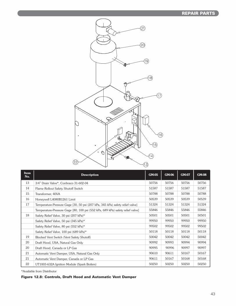
REPAIR PARTS
Figure 12.8: Controls, Draft Hood and Automatic Vent Damper
13
14
15
16
17
18
19
20
20
21
21
22
50756
51587
50788
50539
51324
55846
50501
99950
99502
50118
50042
90994
90997
50167
50168
50250
3/4" Drain Valve*, Conbraco 31-602-04
Flame Rollout Safety Shutoff Switch
Transformer, 40VA
Honeywell L4080B1261 Limit
Temperature-Pressure Gage [30, 50 psi (207 kPa, 345 kPa) safety relief valve]
Temperature-Pressure Gage [80, 100 psi (552 kPa, 689 kPa) safety relief valve]
Safety Relief Valve, 30 psi (207 kPa)*
Safety Relief Valve, 50 psi (345 kPa)*
Safety Relief Valve, 80 psi (552 kPa)*
Safety Relief Valve, 100 psi (689 kPa)*
Blocked Vent Switch (Vent Safety Shutoff)
Draft Hood, USA, Natural Gas Only
Draft Hood, Canada or LP Gas
Automatic Vent Damper, USA, Natural Gas Only
Automatic Vent Damper, Canada or LP Gas
UT1003-632A Ignition Module (Spark Boilers)
ItemNo. Description
50756
51587
50788
50539
51324
55846
50501
99950
99502
50118
50042
90992
90995
90610
90611
50250
50756
51587
50788
50539
51324
55846
50501
99950
99502
50118
50042
90994
90997
50167
50168
50250
50756
51587
50788
50539
51324
55846
50501
99950
99502
50118
50042
90993
90996
90611
50167
50250
GM-05 GM-06 GM-07 GM-08
*Available from Distributor

44
NOTES

GMBoilers
SeriesGas
Installation,Operation &MaintenanceManualTO THE INSTALLER:
This manual is the property of the owner and mustbe affixed near the boiler for future reference.
TO THE OWNER:This boiler should be inspected annually by aQualified Service Agency.
GM8065 R9 (6/09-2M)Printed in U.S.A.©2009
PB HEAT, LLC131 S. CHURCH STREET • BALLY, PA 19503
ASME


![[American Society of Plumbing Engineers] Plumbing](https://static.fdocuments.us/doc/165x107/577cb1c91a28aba7118bddeb/american-society-of-plumbing-engineers-plumbing.jpg)