Series C Helical Worm - Benzlersradicon/_docs/seriesc inch US.pdfSERIES C 1 Series C right angle...
102
Series C Helical Worm Technical Up to - 60 HP / 89,000 lb.in Geared Motors CC-2.00US1211
Transcript of Series C Helical Worm - Benzlersradicon/_docs/seriesc inch US.pdfSERIES C 1 Series C right angle...

Series C Helical Worm
TechnicalUp to - 60 HP / 89,000 lb.in
Geared MotorsCC-2.00US1211

We can create custom engineered transmission solutions of any size and configuration.
Serving an entire spectrum of mechanical drive applications from food, energy, mining and metal; to automotive, aerospace and marine propulsion, we are here to make a positive difference to the supply of drive solutions.
We offer a wide range of repair services and many years experience of repairing demanding and highly critical transmissions in numerous industries.
Series XCone RingPin and bush elastomer coupling
Series XTorque LimiterOverload protection device
Series JShaft mounted helical speed reducers
Series CRight angle drive helical worm geared motors & reducers
Series BDScrewjack wormgear unit
Series GHelical parallel shaft & bevel helical right angle drive gear units
Series XGridDouble flexing steel grid coupling
Series MIn-line helical geared motors & reducers
Series HLarge helical parallel shaft & bevel helical right angle drive units
Roloid Gear PumpLubrication and fluid transportation pump
Series BSWorm gear unit
Series XNyliconGear coupling with nylon sleeve
Series AWorm Gear units and geared motors in single & double reduction types
Series XGearTorsionally rigid,high torque coupling
Series KRight angle helical bevel helical geared motors & reducers
Series FParallel angle helical bevel helical geared motors & reducers
PRODUCTS IN THE RANGE

SERIES C
i
NOTES

SERIES C
ii
General Description 2
Unit Designations 3
Explanation and use of Ratings and Service Factors 4
Load Classification by Applications 5
Selection Procedure 6 - 7
Output Options 8 - 9
Motor Adaptors 10 - 12
Lubrication 13
Mounting Positions 14
Unit Handings 15
MOTORIZED
Motor Details 18
Additional Motor Features 19
Additional Gearbox Features 20
Selection Tables - Geared Motors 21 - 44
Dimension Sheets - Geared Motors 45 - 50
Motorized Backstop Module 51
REDUCER
Overhung & Axial Loads on Shafts 54
Ratings - Input Power / Output Torque 55 - 78
Dimension Sheets - Speed Reducers 79 - 84
Dimension Sheet - Units fitted with Feet 85 - 86
Thermal Power Ratings / Dimensions of Unit with Fan 87 - 88
Reducer Backstop Module 89
OUTPUT OPTIONS
Dimensions of Outputshaft Options 90
Dimension Sheet - Torque Bracket 91
Dimensions of B5 (D) Flange units 92
Dimensions of B14 (C) Flange units 93
Agitator Units 94
Dimension Sheet - Assembly / Disassembly 95 - 96
Shipping Specification 97
CONTENTS PAGE

SERIES C
1
Series C right angle helical worm geared motors and reducers provide a highly efficient and compact solution to meet most requirements up to 60 HP with maximum output torque capacity of 88,500 Lb-In.
Following a long line of power transmission products, this product adds to the growing family of new drives which has taken advantage of our many years of accumulated design expertise, together with the use of high quality materials and components. The end result is a series of speed reducing and geared motors offering high load carrying capacity, increased efficiency, quiet running and reliability.
The Range Includes
Eight sizes of units with a ratio coverage of 8:1 to 250:1 in double reduction and 16000:1 in combined units.
Version W - Standard unit (C03 - C06 Only)Version B - Standard unit with base mounted feetVersion E - Standard unit with end mounted feetVersion R - Standard unit with top mounted feetVersion V - Standard unit with Drywell and
output flange for mounting positions 2 & 3 (sizes C07 - C10 only)
Version F/H - Standard unit with output flangeVersion G - Standard unit with output flange
reduced dia (size C03 only)Version T/Q - Standard unit with Banjo torque armVersion U - Standard unit Banjo torque arm
Heavy Duty (C10 only)Version A - Agitator (Sizes C07 - C10 only)
Unit Types:
Unit type M - Motorized with IEC standard motorUnit type N - Motorized with NEMA standard motorUnit type H - Motorized with high efficiency motor (IE2 or
EPACT)Unit type E - Motorized with NEMA high efficiency motor
(EPACT)Unit type G - Unit to allow fitting of customers IEC motorUnit type A - Unit to allow fitting of customers NEMA motorUnit type R - Reducer unitUnit type S - Reducer unit with fan kitUnit type W - Reducer unit with backstop CCW rotationUnit type X - Reducer unit with backstop CW rotationUnit type Y - Reducer unit with fan and backstop CW rotationUnit type Z - Reducer unit with fan and backstop CCW rotation
Design Features Include
Patented standard motor connection (IEC or NEMA).
Ability to fit double oil seals input and output as required.
All units are dimensionally interchangeable with other major manufacturers.
Brake geared motors are available as standard.
Sizes 03, 04, 05 and 06 are lubricated for life.
Motorized units can be fitted with a backstop module and reducer units can be fitted with a backstop and fan.
Units are manufactured and assembled from a family of modular kits for distributor friendliness minimising inventory and maximising availability.
As improvements in design are being made continually this specification is not to be regarded as binding in detail and drawings and capacities are subject to alteration without notice. Certified drawings will be sent on request.
Two stage reduction unit with base mounted feet and hollow output shaft
Four stage Motorized unit with end mounted feet and hollow output shaft
* Typical unit designations
Four stage reduction unit with base mounted feet and hollow output shaft
Two stage reduction unit with output flange and single extension output shaft
Two stage Motorized unit with output flange and single extension output shaft
* C 0 5 4 1 2 8 0 W R A - 1 - - - - - - -
* C 0 5 2 1 1 1 2 F N N - 1 A 0 . 5 B - -
* C 0 4 4 1 2 8 0 B R A - 1 - - - - - - -
* C 0 5 2 1 1 6 0 F R N - 1 - - - - - - -
* C 0 4 2 1 1 8 . B R A - 1 - - - - - - -
* C 0 4 4 1 2 8 0 E N A - 1 A . 2 5 B - -
Four stage reduction unit with hollow output shaft
GENERAL DESCRIPTION

SERIES C
2
2, 3 - Size of Unit
0 3 Through 1 0
5 - Revision Version
1 For Sizes 03 to 10
1 - Series C
Range C
10. - Type of Unit
M - Motorized with IEC standard motor
N - Motorized with NEMA standard motor
H - Motorized with IEC high efficiency motor (IE2 or EPACT)
E - Motorized with NEMA high efficiency motor (EPACT)
G - Unit to allow fitting of IEC motor (non std motor)
A - Unit to allow fitting of NEMA motor (non std motor)
R - Reducer unit
S - Reducer unit with fan kit
W - Reducer unit with backstop CCW rotation
X - Reducer unit with backstop CW rotation
Y - Reducer unit with fan and backstop CW rotation
Z - Reducer unit with fan and backstop CCW rotation
4 - No of Reductions
2 3 & 4
9 - Unit Version
W - Standard Unit (C03 - C06 Only)
B - Standard Unit with Base Mounted Feet
E - Standard Unit with End Mounted Feet
R - Standard Unit with Top Mounted Feet
V - Standard Unit with Drywell and Output Flange For Mounting Position 2 & 3 (Sizes C07 - C10 only)
Std Unit with Output Flange F on Left † H on Right †
G - Std Unit with Output Flange Reduced Dia (C03 Only)
Std Unit with Banjo Torque Arm T on Left † Q on Right †
U - Std Unit Banjo Torque Arm Heavy Duty (C10 Only)
6,7,8 - Nominal Overall Ration
E.g. 5 0 .
*Example
Gearbox Codes Motor Codes
1 2 3 4 5 6 7 8 9 10 11 12 13 14 15 16 17 18 19 20
C
C 0 3 2 1 5 0 . B M C - 1 D . 1 8 A - -
18 -
11 -
19 -
20 -
Additional Motor Features
e.g. - A
For Types Without Motor Enter -
Additional Gearbox Features Double Oil Seal, Motorized Backstop Etc
e.g. - F
Output Shaft
Standard Single Extension N on Left † B on Right †
Standard Double Extension P
Extended Shaft for Flange Mounted Units G
Standard Hollow Shaft A
Unit with Hollow Shaft with Reduced Bore Dia Z
12 -
13, 14 - Mounting Position
e.g. 2 B
15, 16, 17 - Geared Motor Powers
Motor Power Required
e.g. . 7 5
For reducer and non standard
motor types enter - - -
Motor Adaptor For Unit Types Column 10 Entries M, N, H, E, G or A
For All Other Types Enter -
† Looking on Inputshaft Mounting Position 1 (See page 16 for unit handings)
No of Motor Features
- No motor 50 Hz 60 Hz
4 Pole (Std) 1500 rpm A 1800 rpm B
4 Pole (High)1500 rpm K 1800 rpm L
6 Pole (Std) 1000 rpm C 1200 rpm D
6 Pole (High)1000 rpm M 1200 rpm N
2 Pole 3000 rpm E 3600 rpm F
8 Pole 750 rpm G 900 rpm H
S Dual speed or special motor
This Page May Be Photocopied Allowing The Customer To Enter Their OrderTo access the on line configurator please visit www.swift-gears.com
See output options pages for metric shaft options
UNIT DESIGNATIONS

SERIES C
3
Mass acceleration factor = all external moments of inertia * moment of inertia of driving motor
* calculated with reference to the motor speed
Gear unit selection is made by comparing actual loads with catalogue ratings. Catalogue ratings are based on a standard set of loading conditions, whereas actual load conditions vary according to type of application. Service Factors are therefore used to calculate an equivalent load to compare with catalogue ratings. i.e. Equivalent Load = Actual Load x Service Factor
Mechanical ratings and service factor Fm
Mechanical ratings measure capacity in terms of life and/or strength, assuming 10 hr/day continuous running under uniform load conditions.
Catalogue ratings allow 100% overload at starting, braking or momentarily during operation up to 10 hours per day.
The unit selected must therefore have a catalogue rating at least equal to half maximum overload.
Mechanical Service Factor Fm (Table 1) is used to modify the actual load according to daily operating time, and type of loading.
Load characteristics for a wide range of applications are detailed in Table 3 opposite, which are used in deciding the appropriate Service Factor Fm from Table 1.
If overloads can be calculated, or accurately assessed, actual loads should be used instead of Fm.
For units subjected to frequent stop/starts overloads in excess of 10 times/day multiply factor Fm x Factor Fs (table 2).
Table 1. Mechanical Service Factor (Fm)
Thermal Rating (For In-line Reducers)
The Thermal Rating is the gearboxes ability to dissipate heat. If exceeded, may cause the lubricant to break down resulting in premature gear failure. A thermal check should be made in accordance with procedure (page 90) for in line reducers.
Prime moverDuration of service hrs per day
Load classification-driven machineUniform mass accelerationfactor < 0.2
Moderate mass acceleration
factor < 3
Heavy mass accelerationfactor < 10
Electric motor, steam turbine or hydraulic motor
Under 3 0.80 1.00 1.503 to 10 1.00 1.25 1.75Over 10 1.25 1.50 2.00
Multi-cylinder internal combustion engine
Under 3 1.00 1.25 1.753 to 10 1.25 1.50 2.00Over 10 1.50 1.75 2.25
Single cylinder internal combustion engine
Under 3 1.25 1.50 2.003 to 10 1.50 1.75 2.25Over 10 1.75 2.00 2.50
Table 2. Number of Starts Factor (Fs)
Note: (1) Intermediate values are obtained by linear interpolation
Start / Stops per hour (1) Up to 1 5 10 40 60 > 200
Factor Fs 1.00 1.03 1.06 1.10 1.15 1.20
EXPLANATION & USE OF RATINGS& SERVICE FACTORS

SERIES C
4
log haul Hpresses Mpulp machine reel Mstock chest Msuction roll Mwashers and thickeners Mwinders M
Printing presses
Pullers barge haul H
Pumpscentrifugal Uproportioning Mreciprocating single acting; 3 or more cylinders M double acting; 2 or more cylinders M single acting; 1 or 2 cylinders double acting; single cylinderrotary gear type U lobe, vane U
Rubber and plastics industriescrackers Hlaboratory equipment Mmixed mills Hrefiners Mrubber calenders Mrubber mill-2 on line Mrubber mill-3 on line Msheeter Mtire building machines tire and tube pressopeners tubers and strainers Mwarming mills M
Sand muller M
Sewage disposalequipment bar screens Uchemical feeders Ucollectors Udewatering screws Mscum breakers Mslow or rapid mixers Mthickeners Mvacuum filters M
Screensair washing U rotary-stone or gravel M travelling water intake U
Slab pushers M
Steering gear
Stokers U
Sugar industrycane knives Mcrushers Mmills M
Textile industrybatchers Mcalenders Mcards Mdry cans Mdryers Mdyeing machinery Mknitting machines looms Mmangles Mnappers Mpads Mrange drives slashers Msoapers Mspinners Mtenter frames Mwashers Mwinders M
Windlass
Cranesmain hoists bridge travel trolley travel
Crusher ore Hstone Hsugar H
Dredges cable reels Mconveyors Mcutter head drives Hjig drives Hmaneuvering winches Mpumps Mscreen drive Hstackers Mutility winches M
Dry dock cranes main hoist auxiliary hoist boom, luffing rotating, swing or slew tracking, drive wheels
Elevatorsbucket-uniform load Ubucket-heavy load Mbucket-continuous Ucentrifugal discharge Uescalators Ufreight Mgravity discharge Uman lifts passenger
Fans centrifugal Ucooling towers induced draft forced draft induced draft Mlarge, mine, etc Mlarge, industrial Mlight, small diameter U
Feedersapron Mbelt Mdisc Ureciprocating Hscrew M
Food industry beef slicer Mcereal cooker Udough mixer Mmeat grinders M
Generators-not welding U
Hammer mills H
Hoists heavy duty H medium duty M skip hoist M
Laundry washersreversing M
Laundry tumblers M
Line shaftsdriving processing equipment Mlight Uother line shafts U
Lumber industrybarkers-hydraulic-mechanical Mburner conveyor Mchain saw and drag saw Hchain transfer Hcraneway transfer Hde-barking drum Hedger feed Mgang feed Mgreen chain Mlive rolls Hlog deck H
Agitatorspure liquids Uliquids and solids Mliquids-variable density M
Blowerscentrifugal Ulobe Mvane U
Brewing and distillingbottling machinery Mbrew kettles-continuous duty Mcookers-continuous duty Mmash tubs-continuous duty Mscale hopper-frequent starts M
Can filling machines M
Cane knifes M
Car dumpers H
Car pullers M
Clarifiers U
Classifiers M
Clay working machinery brick press Hbriquette machine Hclay working machinery Mpug mill M
Compressors centrifugal Ulobe Mreciprocating multi-cylinder M single cylinder H
Conveyors-uniformly loaded or fedapron Uassembly Ubelt Ubucket Uchain Uflight Uoven Uscrew U
Conveyors-heavy duty not uniformly fedapron Massembly Mbelt Mbucket Mchain Mflight Mlive rolloven Mreciprocating Hscrew Mshaker H
type ofloadDriven Machine
log haul-incline Hlog haul-well type Hlog turning device Hmain log conveyor Hoff bearing rolls Mplaner feed chains Mplaner floor chains Mplaner tilting hoist Mre-saw merry-go-roundconveyor Mroll cases Hslab conveyor Hsmall waste conveyor-belt Usmall waste conveyor-chain Msorting table Mtipple hoist conveyor Mtipple hoist drive Mtransfer conveyors Mtransfer rolls Mtray drive Mtrimmer feed Mwaste conveyor M
Machine tools bending roll Mpunch press-gear driven Hnotching press- beltdrivenplate planers Htapping machine Hother machine tools main drives M auxiliary drives U
Metal millsdraw bench carriage and main drive Mpinch, dryer and scrubber rolls-reversing slitters Mtable conveyorsnon-reversing group drives M individual drives Hreversing wire drawing and flattening machine Mwire winding machine M
Mill-rotary typeball Hcement kilns Hdryers and coolers Hkilns, other than cement Hpebble Hrod plain H wedge bar Htumbling barrels H
Mixers concrete mixers -continuous Mconcrete mixers -intermittent Mconstant density Uvariable density M
Oil industrychillers Moil well pumping paraffin filter press Mrotary kilns M
Paper millsagitators, (mixers) Mbarker-auxiliaries-hydraulic Mbarker-mechanical Hbarking drum Hbeater and pulper Mbleacher Ucalenders Mcalenders-super Hconverting machine,except cutters, platers Mconveyors Ucouch Mcutters-plates Hcylinders Mdryers Mfelt stretcher Mfelt whipper Hjordans M
Driven Machine Driven Machine Driven Machinetype ofload
type ofload
type ofload
Table 3
U = Uniform load
M = Moderate shock load
H = Heavy shock load
= Refer to Application Engineering
LOAD CLASSIFICATIONS BY APPLICATIONS

SERIES C
5
EXAMPLE APPLICATION DETAILSAbsorbed power of driven machine = 1.3HPOutput speed of gearbox or Input speed of machine = 130 rev/minApplication = Uniformly loaded belt conveyorDuration of service (hours per day) = 24hrsMounting position = 1Ambient temperature = 70°F Running time (%) = 100%
1 DETERMINE MECHANICAL SERVICE FACTOR (Fm)
Refer to Load Classification by Application, table 3, page 5
Application = Uniformly loaded belt conveyor
Refer to mechanical service factor (Fm), table 1, page 4
Duration of service (hours per day) = 24hrs
Conveyors-uniformlyloaded or fed
apron Uassembly Ubelt Ubucket Uchain U
U = Uniform load
2 DETERMINE REQUIRED OUTPUT TORQUE AT GEARBOX OUTPUTSHAFT
Absorbed = Absorbed HP x 6300output torque Gearbox output speed
1.3 x 63000 = 630 lb-in 68
3 SELECT GEARED MOTOR
Refer to selection table one motor size larger than absorbed power. Absorbed power = 1.3 HP, therefore refer to 1.5 HP selection table
Required output speed of gearbox = 130 rev/min
NOTE.
If selecting a Series C ReducerUnit, a Thermal CheckMUST be made in accordancewith procedure on page 87
Duration ofservice hrsper day Moderate
Electric motor,steam turbineorhydraulic motor
Prime mover
Under 3 0.80 1.00
3 to 10 1.00 1.25
Över 10 1.25 1.50
Uniform
Load classification-drive
Therefore mechanical service factor (Fm) = 1.25
If the unit is subject to frequent start/stops Fm must be multiplied by factor Fs (see table 2 page 4)
Go to point 4
201 8.59 394 1.74 625 C 0 3 2 1 8 . 0 _ _ _ _ _ _ 1 . 5 B _ _ 62.7 145TC 149 11.61 527 1.41 625 1 1 . 131 13.20 595 1.29 625 1 2 . 115 14.95 672 1.18 625 1 4 . 105 16.36 657 1.12 625 1 6 . 90 19.13 855 0.99 625 1 8 . 84 20.61 921 0.93 575 2 0 . 78 22.11 873 0.92 575 2 2 . 69 25.14 987 0.84 525 2 5 .
Output Speed
Output Torque
ServiceFactor
Overhung Load
Unit Designation
Column EntrySpaces to be filled when entering order
N2 i lb-in Fm lb
RatioWeight Motor
Size
4 POLE1750 rpm nominal
input speed
1.5 HP
SELECTION PROCEDUREFOR MOTORIZED UNITS

SERIES C
6
4 CHECK OUTPUT TORQUE
Output torque (M2) of selected unit must be equal or more than required output torque at gearbox outputshaft.
Required output torque at gearbox outputshaft = 630 lb.in
However the output torque is only 595 against the requirement of 630 lb.in, hence a unit fitted with a 2HP motor is required.
Selected unit’s output torque (M2) = 794 lb.in, therefore the torque from a 2HP motor is acceptable.
5 CHECK SERVICE FACTOR
Service factor (Fm) of selected unit must be equal or more than required service factor.
Required service factor of gearbox = 1.25
The service factor (Fm) is only 0.96, therefore this unit is not acceptable.and a larger C0421 unit must be selected with a service factor (Fm) of 1.60
5 CHECK OVERHUNG LOADS
If sprocket, gear, etc is mounted on the outputshaft then refer to Overhung Loads Procedure, page 54, and compare with allowable overhung load (lb) of selected unit
Allowable overhung load (lb) must be equal or more than calculated overhung load requirement
NOTE: If any of the following conditions occur then consult our Application Engineers:-
a) Inertia of the Driven Machine (Referred to motor speed) >10 b) Ambient temperature is above 104ºC Inertia of Gear Unit plus Motor
1.5 HPOutput Speed
Output Torque
ServiceFactor
Overhung Load
Unit Designation
Column EntrySpaces to be filled when entering order
N2 i lb-in Fm lb
RatioWeight Motor
Size
4 POLE 201 8.59 394 1.74 625 C 0 3 2 1 8 . 0 _ _ _ _ _ _ 1 . 5 B _ _ 62.7 145TC 149 11.61 527 1.41 625 1 1 . 131 13.20 595 1.29 625 1 2 . 115 14.95 672 1.18 625 1 4 . 105 16.36 657 1.12 625 1 6 .
2 HPOutput Speed
Output Torque
ServiceFactor
Overhung Load
Unit Designation
Column EntrySpaces to be filled when entering order
N2 i lb-in Fm lb
RatioWeight Motor
Size
2 HPOutput Speed
Output Torque
ServiceFactor
Overhung Load
Unit Designation
Column EntrySpaces to be filled when entering order
N2 i lb-in Fm lb
RatioWeight Motor
Size
201 8.59 526 1.30 625 C 0 3 2 1 8 . 0 _ _ _ _ _ _ 2 . 0 B _ _ 69.7 145TC 149 11.61 703 1.06 625 1 1 . 131 13.20 794 0.96 625 1 2 . 115 14.95 896 0.89 560 1 4 . 105 16.36 876 0.84 525 1 6 .
201 8.59 536 2.16 1180 C 0 4 2 1 8 . 0 _ _ _ _ _ _ 2 . 0 B _ _ 69.7 145TC 149 11.61 719 1.76 1180 1 1 . 131 13.20 813 1.60 1180 1 2 . 115 14.95 918 1.47 1180 1 4 .
201 8.59 526 1.30 625 C 0 3 2 1 8 . 0 _ _ _ _ _ _ 2 . 0 B _ _ 69.7 145TC 149 11.61 703 1.06 625 1 1 . 131 13.20 794 0.96 625 1 2 . 115 14.95 896 0.89 560 1 4 . 105 16.36 876 0.84 525 1 6 .
1.5 HP
2 HP
2 HP
2 HP
SELECTION PROCEDUREFOR MOTORIZED UNITS

SERIES C
7
OUTPUTSHAFT OPTIONS,COLUMN 11 ENTRY
Column 11 Entry
Standard Single Extension C on Left E on Right
Standard Double Extension D
Std Extended Shaft for Flange Mounted Units F
Std Heavy Duty Single Extension (Size C06) J
Std Heavy Duty Double Extension (Size C06) K
Inch Single Extension N on Left B on Right
Inch Double Extension P
Inch Extended Shaft for Flange Mount Units G
Inch Heavy Duty Single Extension (Size C06) L
L11* L12
Lt
u
ødTapped Holew
* Inch shafts have open ended keyways, therefore no ‘L11’ dimension is required
SIZE OF
UNIT
TYPE OFOUTPUT SHAFT
COLUMN 11
ENTRY
DIMENSIONS IN MM (Inch shaft in inches)
�d L L11 L12 t u w
C03Standard C, E, D 20.015 / 20.002 35 3 31 2 2.5 6 M6 x 1.0 x 16 Deep
Inch N, B, P 0.7500” / 0.7495” 1.38” * 1.28” 0.83” 0.19” 1/4 UNF x 0.63” Deep
C04 Standard C, E,D 25.015 / 25.002 46 3 42 28 8 M10 x 1.5 x 22 Deep
Inch N, B, P 1.0000” / 0.9995” 1.81” * 1.69” 1.10” 0.25” 1/4 UNF x 0.63” Deep
C05 Standard C, E, D 30.015 / 30.002 60 3 53 33 8 M10 x 1.5 x 22 Deep
Inch N, B, P 1.2500” / 1.2494” 2.36” * 2.125” 1.36” 0.25” 3/8 UNF x 0.87” Deep
C06
Standard C, E, D 35.018 / 35.002 63 3 55 38 10 M12 x 1.75 x 22 Deep
Standard Heavy Duty J, K 45.018 / 45.002 98 5 80 48.5 14 M16 x 2.0 x 36 Deep
Inch N, B, P 1.3750” / 1.3744” 2.48” * 2.34” 1.51” 0.313” 1/2 UNF x 1.125” Deep
Inch Heavy Duty L 1.7500” / 1.7494” 3.86” * 3.75” 1.92” 0.375” 5/8 UNF x 1.44” Deep
C07
Standard C, E, D 45.018 / 45.002 76 3 70 48.5 14 M16 x 2.0 x 36 Deep
Std Extended Shaft F 45.018 / 45.002 90 3 84 48.5 14 M16 x 2 x 36 Deep
Inch N, B 1.7500” / 1.7494” 2.99” * 2.625” 1.917” 0.375” 5/8 UNF x 1.44” Deep
Inch Extended Shaft G 1.7500” / 1.7494” 3.54” * 2.75” 1.91” 0.375” 5/8 UNF x 1.44” Deep
Inch Double Ext P 1.7500” / 1.7494” 2.99” * 2.625” 1.917” 0.375” 5/8 UNF x 1.44” Deep
C08
Standard C, E, D 60.030 / 60.011 120 3 110 64 18 M20 x 2.5 x 42 Deep
Std Extended Shaft F 60.030 / 60.011 120 3 110 64 18 M20 x 2.5 x 42 Deep
Inch N, B 2.3750” / 2.3744” 4.72” * 4.125” 2.646” 0.625” 3/4 UNF x 1.75” Deep
Inch Extended Shaft G 2.3750” / 2.3744” 4.72” * 3.25” 2.64” 0.625” 3/4 UNF x 1.75” Deep
Inch Double Ext P 2.3125” / 2.3115” 4.72” * 4.125” 2.582” 0.625” 3/4 UNF x 1.75” Deep
C09
Standard C, E, D 70.030 / 70.011 135 3 125 74.5 20 M20 x 2.5 x 42 Deep
Std Extended Shaft F 70.030 / 70.011 140 3 125 74.5 20 M20 x 2.5 x 42 Deep
Inch N, B 2.8750” / 2.8740” 5.12” * 4.5” 3.20” 0.75” 3/4 UNF x 1.75” Deep
Inch Extended Shaft G 2.8750” / 2.8740” 5.51” * 3.50” 3.20” 0.75” 3/4 UNF x 1.75” Deep
Inch Double Ext P 2.6875” / 2.6865” 5.12” * 4.5” 2.963” 0.625” 3/4 UNF x 1.75” Deep
C10
Standard C, E, D 90.035 / 90.013 170 3 160 95 25 M24 x 3.0 x 50 Deep
Std Extended Shaft F 90.035 / 90.013 170 3 160 95 25 M24 x 3.0 x 50 Deep
Inch N, B 3.6250” / 3.6240” 6.69” * 5.875” 4.009” 0.875” 1 UNF x 2.25” Deep
Inch Extended Shaft G 3.6250” / 3.6240” 6.69” * 5.51” 4.00” 0.875” 1 UNF x 2.25” Deep
Inch Double Ext P 3.1875” / 3.1865” 6.69” * 5.875” 3.518” 0.750” 1 UNF x 2.25” Deep
OUTPUT OPTIONS

SERIES C
8
OUTPUT BORE OPTIONS,COLUMN 11 ENTRY
Column 11 Entry
Metric Hollow Shaft H
Inch Hollow Shaft A
Metric Hollow Shaft with reduced bore diameter Zm1
m m
m2
m3
UT
øD
Standard / Inch Hollow Shaft
Setscreww3
Output Shaft Bore
SIZE OF
UNIT
TYPE OFBORE
COLUMN 11
ENTRY
DIMENSIONS IN MM (Inch shaft in inches)
�D m m1 m2 �m3 T U w3
C03Standard H 20.021/20.000 52 124 104 20.2 22.9 6 M6 x 1.0, 40
Inch A 0.7508”/0.7500” 2.05” 4.88” 4.13” 0.76” 0.84” 0.188” 1/4” UNF x 11/2”
C04
Standard H 30.021/30.000 54 130 122 30.2 33.5 8 M10 x 1.5, 50
Reduced Dia Z 25.021/25.000 54 130 125 25.2 28.5 8 M10 x 1.5, 50
Inch A 1.2510”/1.2500” 2.13” 5.12” 4.81” 1.26” 1.37” 0.25” 3/8 UNF x 2”
C05
Standard H 35.025/35.000 56 140 127 35.3 38.5 10 M12 x 1.75, 55
Reduced Dia Z 30.021/30.000 56 140 127 30.3 33.5 8 M10 x 1.5 x 45
Inch A 1.3760”/1.3750” 2.20” 5.52” 5.00” 1.39” 1.53” 0.313” 1/2” UNF x 2”
C06
Standard H 45.025/45.000 70 180 156 45.3 49 14 M16 x 2.0, 70
Reduced Dia Z 40.025/40.000 70 180 156 40.3 43.5 12 M16 x 2.0, 70
Inch A 1.5010”/1.5000” 2.76” 7.08” 6.14” 1.51” 1.67” 0.375” 5/8” UNF x 23/4”
C07
Standard H 60.030/60.000 79 218 188 60.5 64.6 18 M20 x 2.5, 80
Reduced Dia Z 50.030/50.000 79 218 191 50.5 54 14 M16 x 2.0, x 70
Inch A 2.0010”/2.0000” 3.11” 8.58” 7.41” 2.02” 2.23” 0.50” 5/8” UNF x 3”
C08
Standard H 70.030/70.000 90 250 220 70.5 75.1 20 M20 x 2.5, 80
Reduced Dia Z 60.030/60.000 90 250 220 60.5 64.6 18 M20 x 2.5, 80
Inch A 2.3760”/2.3750” 3.54” 9.84 8.68” 2.40” 2.66” 0.625” 3/4” UNF x 3”
C09
Standard H 90.035/90.000 107.5 300 265 90.5 95.6 25 M24 x 3.0, 110
Reduced Dia Z 70.030/70.000 107.5 300 270 70.5 75.1 20 M20 x 2.5, 100
Inch A 2.7510”/2.7500” 4.23” 11.82” 10.65” 2.76” 3.04” 0.625” 3/4” UNF x 41/4”
C10
Standard H 100.035/100.000 132.5 350 313 100.5 106.6 28 M24 x 3.0, 110
Reduced Dia Z 80.030/80.000 132.5 350 313 80.5 85.6 22 M20 x 2.5, 100
Inch A 3.2510”/3.2500” 5.22” 13.78” 12.32” 3.26” 3.59” 0.75” 1” UNF x 41/4”
OUTPUTBORE OPTIONS

SERIES C
9
DOUBLE REDUCTION UNITSIEC Flanges B14 - Column 12 Entry For Unit Types Column 10 Entries G, H and M Only
IEC Flanges B5 - Column 12 Entry For Unit Types Column 10 Entries G, H and M Only
NEMA Flanges C Face - Column 12 Entry For Unit Types Column 10 Entries A,E and N Only
MOTORFRAME /FLANGE
UNIT SIZE, NUMBER OF REDUCTIONS, REVISION NUMBERC0321 C0421 C0521 C0621 C0721 C0821 C0921 C1021
RAT
IOC
OV
ER
AG
E
8.0
-28.
36. -
40.
32.
45. -
250
8.0
-28.
36. -
40.
32.
45. -
250
8.0
- 40.
56. -
63.
45. -
50.
71. -
250
8.0
- 28.
36. -
40.
32.
45. -
250
8.0
- 28.
36. -
40.
32.
45. -
250
8.0
- 40.
56. -
63.
45. -
50.
71. -
250
8.0
- 40.
56. -
63.
45. -
50.
71. -
250
8.0
- 40.
56. -
63.
45. -
50.
71. -
250
63
CO
LUM
N12
EN
TRY
F F F F - F - V - - - - - - - -71 G G G G - G - D - - - - - - - -80 A J A J A J W F - F - D - E - -90 C Q C Q C Q Y H - H - E - F - -100 - - - - - - A K A K A F - G - E112 - - - - - - A K A K A F - G - E132 - - - - - - N P C M B G - H - F160 - - - - - - - - E - C H A J A G180 - - - - - - - - - - - - B K B H200 - - - - - - - - - - - - C - C -225 - - - - - - - - - - - - D - D -
MOTORFRAME /FLANGE
UNIT SIZE, NUMBER OF REDUCTIONS, REVISION NUMBERC0321 C0421 C0521 C0621 C0721
RAT
IO
CO
VE
RA
GE
8.0
-28.
36. -
40.
32.
45. -
250
8.0
-28.
36. -
40.
32.
45. -
250
8.0
- 40.
56. -
63.
45. -
50.
71. -
250
8.0
- 28.
36. -
40.
32.
45. -
250
8.0
- 28.
36. -
40.
32.
45. -
250
71
CO
LUM
N12
EN
TRY
H H H H - H - - - -80 B K B K B K - G - G90 D R D R D R Z J - J
100 E S E S E S B L B L112 E S E S E S B L B L132 - - - - - - - - D N
MOTORFRAME /FLANGE
UNIT SIZE, NUMBER OF REDUCTIONS, REVISION NUMBERC0321 C0421 C0521 C0621 C0721 C0821 C0921 C1021
RAT
IO
CO
VE
RA
GE
8.0
-28.
36. -
40.
32.
45. -
250
8.0
-28.
36. -
40.
32.
45. -
250
8.0
- 40.
56. -
63.
45. -
50.
71. -
250
8.0
- 28.
36. -
40.
32.
45. -
250
8.0
- 28.
36. -
40.
32.
45. -
250
8.0
- 40.
56. -
63.
45. -
50.
71. -
250
8.0
- 40.
56. -
63.
45. -
50.
71. -
250
8.0
- 40.
56. -
63.
45. -
50.
71. -
250
56c
CO
LUM
N12
EN
TRY
T U T U T U - Q - Q - M - - - -143/145TC V W V W V W - R - R - N - - - -182/184TC X - X - X - S T S T J P - S - P213/215TC - - - - - - U - U V K Q - T - Q254/256TC - - - - - - - - W - L U P U L R284/286TC - - - - - - - - - - - - Q V M S324/326TC - - - - - - - - - - - - R W N T
Limited Availability / Non Preferred
MOTOR ADAPTERS

SERIES C
10
MOTORFRAME /FLANGE
UNIT SIZE, NUMBER OF REDUCTIONS, REVISION NUMBERC0331 C0431 C0531 C0631 C0731
RAT
IO
CO
VE
RA
GE
132
- 150
100
- 118
160
- 900
132
- 150
100
- 118
160
- 900
132
- 150
100
- 118
160
- 900
100
- 150
200
- 225
160
- 180
265
- 900
132
- 150
100
- 118
160
- 900
71
CO
LUM
N 1
2 H H H H H H - H - -80 B K B K B K B K - G90 D R D R D R D R Z J100 E S E S E S E S B L112 - - - - - - - - B L
TRIPLE REDUCTION UNITS
IEC Flanges B14 - Column 12 Entry For Unit Types Column 10 Entries G, H and M Only
IEC Flanges B5 - Column 12 Entry For Unit Types Column 10 Entries G, H and M Only
NEMA FLANGES C Face - Column 12 Entry For Unit Types Column 10 Entries A, E and N Only
MOTORFRAME /FLANGE
UNIT SIZE, NUMBER OF REDUCTIONS, REVISION NUMBERC0331 C0431 C0531 C0631 C0731
RAT
IO
CO
VE
RA
GE
132
- 150
100
- 118
160
- 900
132
- 150
100
- 118
160
- 900
132
- 150
100
- 118
160
- 900
100
- 150
200
- 225
160
- 180
265
- 900
132
- 150
100
- 118
160
- 900
63
CO
LUM
N 1
2
F F F F F F - F - V71 G G G G G G - G - D80 A J A J A J A J W F90 C Q C Q C Q C Q Y H
100 - - - - - - - - A K112 - - - - - - - - A K132 - - - - - - - - N P
MOTORFRAME /FLANGE
UNIT SIZE, NUMBER OF REDUCTIONS, REVISION NUMBERC0331 C0431 C0531 C0631 C0731
RAT
IOC
OV
ER
AG
E
132
- 150
100
- 118
160
- 900
132
- 150
100
- 118
160
- 900
132
- 150
100
- 118
160
- 900
100
- 150
200
- 225
160
- 180
265
- 900
132
- 150
100
- 118
160
- 900
56c
CO
LUM
N 1
2 T U T U T U T U - Q143/145TC V W V W V W V W - R182/184TC X - X - X - X - S T213/215TC - - - - - - - - U -
Limited Availability / Non Preferred
MOTOR ADAPTERS

SERIES C
11
QUADRUPLE REDUCTION UNITS
IEC Flanges B14 - Column 12 Entry For Unit Types Column 10 Entries G, H and M Only
IEC Flanges B5 - Column 12 Entry For Unit Types Column 10 Entries G, H and M Only
NEMA Flanges C Face - Column 12 Entry For Unit Types Column 10 Entries A, E and N Only
MOTORFRAME /FLANGE
UNIT SIZE, NUMBER OF REDUCTIONS, REVISION NUMBERC0341 C0441 C0541 C0641 C0741 C0841 C0941 C1041
RAT
IOC
OV
ER
AG
E
All
Rat
ios
All
Rat
ios
All
Rat
ios
All
Rat
ios
All
Rat
ios
500
560
& O
ver
500
560
& O
ver
450
560
& O
ver
71
CO
LUM
N 1
2 EN
TRY H H H H H - - - - - -
80 K K K K K - G - G - G90 R R R R R Z J Z J - J
100 S S S S S B L B L B L112 - - - - - B L B L B L132 - - - - - - - - - D N
MOTORFRAME /FLANGE
UNIT SIZE, NUMBER OF REDUCTIONS, REVISION NUMBERC0341 C0441 C0541 C0641 C0741 C0841 C0941 C1041
RAT
IOC
OV
ER
AG
E
All
Rat
ios
All
Rat
ios
All
Rat
ios
All
Rat
ios
All
Rat
ios
500
560
& O
ver
500
560
& O
ver
450
560
& O
ver
56c
CO
LUM
N 1
2 E
NTR
Y
U U U U U - Q - Q - Q
143/145TC W W W W W - R - R - R
182/184TC - - - - - S T S T S T
213/215TC - - - - - U - U - U V
MOTORFRAME /FLANGE
UNIT SIZE, NUMBER OF REDUCTIONS, REVISION NUMBERC0341 C0441 C0541 C0641 C0741 C0841 C0941 C1041
RAT
IOC
OV
ER
AG
E
All
Rat
ios
All
Rat
ios
All
Rat
ios
All
Rat
ios
All
Rat
ios
500
560
& O
ver
500
560
& O
ver
450
560
& O
ver
63
CO
LUM
N 1
2 E
NTR
Y
F F F F F - V - V - -71 G G G G G - D - D - -80 J J J J J W F W F - F90 Q Q Q Q Q Y H Y H - H
100 - - - - - A K A K A K112 - - - - - A K A K K K132 - - - - - N P N P C M160 - - - - - - - - - E -
Limited Availability / Non Preferred
MOTOR ADAPTERS

SERIES C
12
LUBRICANT AND QUANTITY Unit sizes C03, 04, 05 and 06 are factory filled with a grade 6G lubricant.
Unit sizes C07, 08, 09 and 10 will be despatched without oil.
The oil grade is stamped on the name plate and the oil level should be established by filling until the oil escapes via the level plug,
The grade and level are determined from the operating speed of the gear unit and the ambient temperature range, which if not given when ordering will be assumed to be 1450 rev / min input and ambient temperature range 0 to 95ºF. Oil grades and oil level should always be checked before installation, Consult the Installation and Maintenance instructions provided with the gear unit. To determine the oil grade refer to table 1, and then refer to the Installation and Maintenance instructions to select an approved lubricant To determine the oil capacity refer to appropriate table 2 or 3. Oil capacities are only approximate and units should be filled until oil escapes from the level plug holes. Do not overfill as excess will cause overheating and leakage.
Always fill with correct lubricant as marked on the nameplate. Never mix lubricant grades.
See Installation and Maintenance instructions for lists of approved lubricants within the grades.
Note: Catalogue ratings are based on the polyglycol range of synthetic oils recommended on this page. The use of mineral or special oils will require a derate, please contact our Application Engineers.
Unless stated with the order these operating conditions will be assumed
GEAR UNIT DETAILS AMBIENT TEMPERATURE RANGE *UNIT TYPE RATIO RANGE INPUT SPEED(REV / MIN) -22ºF to 68ºF 32ºF to 95ºF 68ºF to 122ºF
DOUBLES
8 - 18 0 - 750 6G 6G 8G
0>750 - 2000 5G 6G 7G>2000 - 3000 4G 6G 6G
20 - 360 - 2000 6G 6G 8G
>2000 - 3000 5G 6G 7G40 - 250 0 - 3000 6G 6G 8G
QUADRUPLES < - 2800
0 - 750 6G 7G 9G>750 - 3000 6G 6G 8G
3200 - 16000 0 - 3000 6G 7G 9G
TABLE 1 SERIES C OIL GRADES
* For other ambient temperatures please refer to our Application Engineers.
TABLE 2 LUBRICANT QUANTITY (LITERs †) (double reduction and final stage quadruple reduction)
DOUBLE, TRIPLE AND FINAL STAGE QUADRUPLE REDUCTIONUnit Size C0321 C0331 C0421 C0431 C0521 C0531 C0621 C0631 C0721 C0731 C0821 C0921 C1021
MO
UN
TIN
G P
OS
ITIO
N 1 Level 1 *
0.3 0.4 0.4 0.5 0.7 0.9 1.5 2.14.5 4.8 7.1 17 28
Level 2 * 3.0 3.8 5.9 11 172 0.5 0.8 0.7 0.9 1.0 1.4 2.3 2.5 3.5 3.7 6.2 12 213 0.5 0.8 0.7 0.9 1.0 1.4 2.2 2.5 3.7 3.7 6.2 12 21
4 Level 1 *
0.7 1.2 1.0 1.5 1.4 2.1 3.1 4.05.1 5.9 9.5 17 26
Level 2 * 3.0 3.6 4.8 8.3 145 0.6 1.0 0.9 1.3 1.4 2.0 3.0 4.6 5.6 6.6 9.6 18 31
6Level 1 * 0.7 1.2 1.0 1.5 1.4 1.9 3.2 4.0 7.4 9.2 12 25 42Level 2 * 5.1 6.9 9.5 17 28
PRIMARY STAGE QUADRUPLE REDUCTIONUnit Size C0341 C0441 C0541 C0641 C0741 C0841 C0941 C1041SECONDARY UNIT(Lubricant quantity see table 2) C0321 C0421 C0521 C0621 C0721 C0821 C0921 C1021
PRIMARY UNIT M0122 M0122 M0122 M0322 M0322 M0522 M0522 M0722PRIMARY QUANTITY •(Unit lubricant)
1 to 4 0.5 0.5 0.5 0.8 0.8 1.5 1.5 2.65 & 6 1.0 1.0 1.0 1.4 1.4 2.6 2.6 4.7
* Use Level 1 for output speeds lower than 100 rpm * Use Level 2 for output speeds of 100 rpm and higher.
† 1 LITER = 0.26 gallon (US)
TABLE 3 LUBRICANT QUANTITY (LITERs †) (primary stage quadruple reduction)
• Unit filled with Grade 6E lubricant suitable for all ambient temperatures between 32�F to 95�F and are ‘lubricated for life’
LUBRICATION

SERIES C
13
270o
0o
90o
180o
2
6
1
5 3
4
2
1
5 3
6
4
270o
0o
90o
180o
2
6
1
5 3
4
2
1
5 3
6
4
COLUMN 13 ENTRYEnter - for units with no oil fill
COLUMN 14 ENTRY
ALL MOTORS
MOUNTING POSITIONS - SHOWN AS MOTORIZED - APPLIES ALSO FOR REDUCERS
Flange Mounted Units
Base Mounted Units
Column 14 Entry Terminal Box Position
A 0º
B 90º
C 180º
D 270º
- Reducer or no motor fitted
† Gear Units for use in mounting positions 5 and 6 should only be selected with overall ratios greater or equal to those shown in table below
* Mounting Position 6 is not recommended for geared motors - Consult Application Engineering
*
* †
†
†
†
UnitSize
Input Speed (rpm)
1000 1500 1800 >1800
C03-C08 All All All ConsultApplication Engineering
C09 18:1 18:1 25:1
C10 18:1 40:1 63:1
MOUNTING POSITIONS

SERIES C
14
F
T
H
Q
Column 9 Entry
Std Unit withOutput Flange
Std Unit withTorque Bracket
Left Right
Column 11Entry
Metric
Left Right
Single OutputShaft
Double OutputShaft
HollowShaft
Inch
Left Right
NC
PD
AH
BE
UNIT HANDINGS

SERIES C
15

SERIES C
16
MOTORIZED
SERIES C
MOTORIZED

SERIES C
17
NEMA Standard Motors
MOTOR FRAME SIZE Ø BD Ø AJ Ø AK Ø U AH ko
max Ø g BF TAP UNC
56C 6.50 5.875 4.5 0.625 2.062 12.00 6.13 3/8 - 16
143TC/145TC 6.50 5.875 4.5 0.875 2.125 12.00 7.19 3/8 - 16
MOTOR FRAME SIZE Ø BD Ø AJ Ø AK Ø U AH ko max Øg BF TAP
UNC
182TC/184TC 9.00 7.25 8.5 1.125 2.625 15.50 8.50 1/2 - 13
213TC/215TC 9.00 7.25 8.5 1.375 3.125 16.50 10.19 1/2 - 13
254TC/256TC 10.00 7.25 8.5 1.625 3.75 20.00 12.50 1/2 - 13
284TC/286TC 11.25 9.00 10.5 1.875 4.375 23.25 15.56 1/2 - 13
324TC/326TC 13.875 11.00 12.5 2.125 5.00 25.25 16.94 5/8 - 11
364TC/365TC 13.875 11.00 12.5 2.375 5.625 27.00 19.00 5/8 - 11
404TC/405TC 13.875 11.00 12.5 2.875 7.00 30.00 20.63 5/8 - 11
* Motor lengths for our standard motors. These lengths may vary if alternative motor is fitted.
NEMA MOTOR DETAILS
ko
�U
AH
øAKøAJ�BD
BF4 HOLES
� g
ko
�U
AH
øAK �AJ�BD
BF4 HOLES
� g

SERIES C
18
ADDITIONAL MOTOR FEATURES - COLUMN 19 ENTRY
Column 19 Entry Brake Motor Hand Release on Brake
Forced Ventilation/ Constant Blower
(TECB)Thermistors Special
-
A •
B • •
C •
D • •
E • • •
F •
G • •
H • • •
K • •
L • • •
M • • • •
S •
Please refer to Application Engineering for details of the following additional motor features
- PGF encoder flange
- Wash down
- Customised brake torque
- Separate brake supply
- Aluminium fan
- Anti Condensation heater
- Bi-metal temperature detectors, Thermostat
- EExEIIT3
- Ex nA II T3
- IP56
- IP65
- Metal fan cover
- Rain cowl
- Separate terminal box
ADDITIONAL MOTOR FEATURES

SERIES C
19
Please refer to our Application Engineers for details of the following additional gearbox features
- Prime paint only
- Wash down
- BISSC compatible
- Special oil (food compatible, biodegradable, different viscosities etc)
IEC B5 frame sizes 100 - 200 and NEMA frame sizes 182TC -326TC - see page 70 for details
Column 20Entry
Double Output Shaft
Oil Seals
Oil LevelGlass
C07 - C10
* Motorized BackstopSpecial
CW Rotation CCW Rotation
-
A •
B •
C • •
D •
E • •
F • •
G • • •
H •
I • •
J • •
K • • •
L •
ADDITIONAL GEARBOX FEATURES - COLUMN 20 ENTRY
ADDITIONAL GEARBOX FEATURES

SERIES C
20
N2 R/MIN i lb.in Fm lb lb
OutputSpeed Ratio Output
TorqueServiceFactor
OverhungLoad
Unit Designation
Weight MotorSize
Column Entry 1 Through 20 Spacestobefilledwhenenteringorder
NOTE
Other output speeds are available using 2 and 6 pole motors - Consult Application Engineering
20
SELECTION TABLESGEARED MOTORS
201 8.59 65 10.42 625 C 0 3 2 1 8 . 0 _ _ _ _ _ _ . 2 5 B _ _ 46.7 56C 149 11.61 87 8.46 625 1 1 . 131 13.20 99 7.72 625 1 2 . 115 14.95 112 7.09 625 1 4 . 105 16.36 109 6.72 625 1 6 . 90 19.13 142 5.92 625 1 8 . 84 20.61 153 5.60 625 2 0 . 78 22.11 145 5.50 625 2 2 . 69 25.14 164 5.03 625 2 5 . 61 28.48 185 4.63 625 2 8 . 51 33.71 245 3.93 625 3 2 . 47 36.43 233 3.91 625 3 6 . 44 39.26 250 3.72 625 4 0 . 38 45.50 327 3.16 625 4 5 . 32 53.31 380 2.81 625 5 0 . 31 56.19 350 2.90 625 5 6 . 27 64.21 397 2.65 625 6 3 . 23 74.55 526 2.32 625 7 1 . 21 82.83 582 2.14 625 8 0 . 20 86.67 525 2.24 625 9 0 . 17 101.54 611 2.00 625 1 0 0 15 114.33 793 1.72 625 1 1 2 13 129.94 895 1.43 625 1 2 5 12 142.00 834 1.57 625 1 4 0 11 157.78 919 1.45 625 1 6 0 7.9 217.78 1245 1.09 625 2 1 2 7.0 247.50 1408 0.97 600 2 5 0
16 105.36 718 1.83 625 C 0 3 3 1 1 0 0 _ _ _ _ _ _ . 2 5 B _ _ 55.5 56C 14 120.39 820 1.66 625 1 1 8 13 130.10 745 1.65 625 1 3 2 12 140.21 805 1.57 625 1 5 0 11 162.50 1096 1.24 625 1 6 0 9.1 190.38 1276 1.07 625 1 8 0 8.6 200.68 1130 1.21 625 2 0 0 7.5 229.32 1282 1.06 625 2 2 5
23 74.55 532 3.46 1180 C 0 4 2 1 7 1 . _ _ _ _ _ _ . 2 5 B _ _ 53.3 56C 21 82.83 587 2.91 1180 8 0 . 20 86.67 537 3.59 1180 9 0 . 17 101.54 622 3.20 1180 1 0 0 15 114.33 799 1.87 1180 1 1 2 13 129.94 901 1.43 1180 1 2 5 12 142.00 849 2.52 1180 1 4 0 11 157.78 935 2.34 1180 1 6 0 7.9 217.78 1269 1.86 1180 2 1 2 7.0 247.50 1426 1.43 1180 2 5 0
16 105.36 730 2.49 1180 C 0 4 3 1 1 0 0 _ _ _ _ _ _ . 2 5 B _ _ 62.1 56C 14 120.39 830 2.17 1180 1 1 8 13 130.10 765 2.59 1180 1 3 2 12 140.21 822 2.47 1180 1 5 0 11 162.50 1108 1.61 1180 1 6 0 9.1 190.38 1294 1.37 1180 1 8 0 8.6 200.68 1156 1.98 1180 2 0 0 7.5 229.32 1314 1.82 1180 2 2 5 6.5 266.25 1781 0.99 1180 2 6 5 5.8 295.83 1972 0.89 1180 2 8 0 5.6 309.52 1743 1.52 1180 3 1 5 4.8 362.64 2028 1.37 1180 3 6 0 3.4 507.14 2774 0.99 1180 5 0 0 3.1 563.49 3068 0.89 1050 5 6 0
16 109.07 785 3.89 1650 C 0 5 2 1 1 1 2 _ _ _ _ _ _ . 2 5 B _ _ 57.7 56C 14 124.00 886 2.97 1650 1 2 5 8.2 211.11 1277 3.78 1650 2 1 2 7.2 240.00 1438 2.97 1650 2 5 0
4 POLE1750 rpm nominal
input speed
0.25 HP
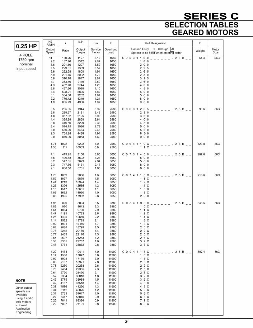
SERIES C
21
N2 R/MIN i lb.in Fm lb lb
OutputSpeed Ratio Output
TorqueServiceFactor
OverhungLoad
Unit Designation
Weight MotorSize
Column Entry 1 Through 20 Spacestobefilledwhenenteringorder
NOTE
Other output speeds are available using 2 and 6 pole motors - Consult Application Engineering
SERIES C
21
SELECTION TABLESGEARED MOTORS
11 160.26 1127 3.12 1650 C 0 5 3 1 1 6 0 _ _ _ _ _ _ . 2 5 B _ _ 64.3 56C 9.2 187.76 1312 2.67 1650 1 8 0 8.6 201.10 1207 3.89 1650 2 0 0 7.5 229.81 1369 3.57 1650 2 2 5 6.6 262.58 1808 1.91 1650 2 6 5 5.9 291.75 2002 1.72 1650 2 8 0 5.6 310.18 1817 2.84 1650 3 1 5 4.7 363.40 2110 2.50 1650 3 6 0 4.3 402.70 2744 1.25 1650 4 0 0 3.8 457.66 3098 1.10 1650 4 5 0 3.4 508.21 2895 1.82 1650 5 0 0 3.1 564.68 3202 1.64 1650 5 6 0 2.2 779.42 4349 1.21 1650 8 0 0 1.9 885.79 4906 1.07 1650 9 0 0
6.5 265.95 1944 3.92 2580 C 0 6 3 1 2 6 5 _ _ _ _ _ _ . 2 5 B _ _ 99.6 56C 5.8 299.67 2181 3.48 2580 2 8 0 4.8 357.32 2195 3.90 2580 3 6 0 4.4 395.39 2858 2.64 2580 4 0 0 3.8 449.50 3229 2.33 2580 4 5 0 3.4 514.75 3086 2.78 2580 5 0 0 3.0 580.00 3454 2.48 2580 5 6 0 2.3 765.28 4488 1.91 2580 8 0 0 2.0 870.00 5063 1.69 2580 9 0 0
1.71 1022 9202 1.0 2580 C 0 6 4 1 1 0 C _ _ _ _ _ _ . 2 5 B _ _ 123.8 56C 1.58 1111 10003 0.9 2580 1 1 C
4.1 419.25 3150 3.85 6050 C 0 7 3 1 4 5 0 _ _ _ _ _ _ . 2 5 B _ _ 207.6 56C 3.5 499.88 3502 3.21 6050 5 0 0 3.2 547.35 3823 2.94 6050 5 6 0 2.3 747.66 5131 2.17 6050 8 0 0 2.1 838.50 5731 1.95 6050 9 0 0
1.73 1009 9086 1.6 6050 C 0 7 4 1 1 0 C _ _ _ _ _ _ . 2 5 B _ _ 218.6 56C 1.59 1097 9879 1.5 6050 1 1 C 1.44 1213 10924 1.4 6050 1 2 C 1.25 1396 12565 1.2 6050 1 4 C 1.15 1517 13661 1.1 6050 1 6 C 1.05 1662 14960 1.0 6050 1 8 C 0.88 1995 17962 0.8 6050 2 0 C
1.95 899 8094 3.5 9380 C 0 8 4 1 9 0 0 _ _ _ _ _ _ . 2 5 B _ _ 346.5 56C 1.82 960 8643 3.3 9380 1 0 C 1.61 1084 9760 2.9 9380 1 1 C 1.47 1191 10723 2.6 9380 1 2 C 1.25 1405 12650 2.2 9380 1 4 C 1.14 1532 13793 2.1 9380 1 6 C 0.92 1901 17116 1.7 9380 1 8 C 0.84 2088 18799 1.5 9380 2 0 C 0.78 2242 20186 1.4 9380 2 2 C 0.71 2463 22176 1.3 9380 2 5 C 0.65 2697 24283 1.2 9380 2 8 C 0.53 3305 29757 1.0 9380 3 2 C 0.47 3761 33862 0.8 9380 3 6 C 1.22 1434 12911 4.0 11900 C 0 9 4 1 1 4 C _ _ _ _ _ _ . 2 5 B _ _ 507.4 56C 1.14 1538 13847 3.8 11900 1 6 C 0.92 1908 17179 3.0 11900 1 8 C 0.83 2107 18971 2.8 11900 2 0 C 0.78 2250 20258 2.6 11900 2 2 C 0.70 2484 22365 2.3 11900 2 5 C 0.64 2720 24490 2.1 11900 2 8 C 0.52 3334 30018 1.8 11900 3 2 C 0.46 3775 33988 1.5 11900 3 6 C 0.42 4167 37518 1.4 11900 4 0 C 0.38 4586 41290 1.3 11900 4 5 C 0.34 5112 46026 1.2 11900 5 0 C 0.31 5733 51617 1.0 11900 5 6 C 0.27 6447 58046 0.9 11900 6 3 C 0.25 7041 63394 0.9 11900 7 1 C 0.22 7897 71101 0.8 11900 8 0 C
0.25 HP4 POLE
1750 rpm nominal
input speed

SERIES C
22
N2 R/MIN i lb.in Fm lb lb
OutputSpeed Ratio Output
TorqueServiceFactor
OverhungLoad
Unit Designation
Weight MotorSize
Column Entry 1 Through 20 Spacestobefilledwhenenteringorder
NOTE
Other output speeds are available using 2 and 6 pole motors - Consult Application Engineering
22
SELECTION TABLESGEARED MOTORS
201 8.59 86 7.89 625 C 0 3 2 1 8 . 0 _ _ _ _ _ _ . 3 3 B _ _ 48.7 56C 149 11.61 116 6.41 625 1 1 . 131 13.20 131 5.85 625 1 2 . 115 14.95 147 5.37 625 1 4 . 105 16.36 144 5.09 625 1 6 . 90 19.13 188 4.49 625 1 8 . 84 20.61 202 4.25 625 2 0 . 78 22.11 192 4.17 625 2 2 . 69 25.14 217 3.81 625 2 5 . 61 28.48 244 3.50 625 2 8 . 51 33.71 324 2.98 625 3 2 . 47 36.43 307 2.96 625 3 6 . 44 39.26 330 2.82 625 4 0 . 38 45.50 432 2.40 625 4 5 . 32 53.31 502 2.13 625 5 0 . 31 56.19 462 2.20 625 5 6 . 27 64.21 524 2.01 625 6 3 . 23 74.55 694 1.76 625 7 1 . 21 82.83 769 1.62 625 8 0 . 20 86.67 693 1.70 625 9 0 . 17 101.54 806 1.51 625 1 0 0 15 114.33 1046 1.30 625 1 1 2 13 129.94 1182 1.09 625 1 2 5 12 142.00 1101 1.19 625 1 4 0 11 157.78 1213 1.10 625 1 6 0 7.9 217.78 1643 0.83 520 2 1 2
16 105.36 948 1.39 625 C 0 3 3 1 1 0 0 _ _ _ _ _ _ . 3 3 B _ _ 57.5 56C 14 120.39 1083 1.26 625 1 1 8 13 130.10 984 1.25 625 1 3 2 12 140.21 1063 1.19 625 1 5 0 11 162.50 1447 0.94 590 1 6 0 9.1 190.38 1684 0.81 520 1 8 0 8.6 200.68 1492 0.91 560 2 0 0 7.5 229.32 1692 0.81 510 2 2 5
32 53.31 509 3.56 1180 C 0 4 2 1 5 0 . _ _ _ _ _ _ . 3 3 B _ _ 55.3 56C 31 56.19 473 3.51 1180 5 6 . 27 64.21 535 3.21 1180 6 3 . 23 74.55 702 2.62 1180 7 1 . 21 82.83 775 2.20 1180 8 0 . 20 86.67 709 2.72 1180 9 0 . 17 101.54 821 2.42 1180 1 0 0 15 114.33 1054 1.42 1180 1 1 2 13 129.94 1190 1.09 1180 1 2 5 12 142.00 1120 1.91 1180 1 4 0 11 157.78 1234 1.77 1180 1 6 0 7.9 217.78 1676 1.41 1180 2 1 2 7.0 247.50 1883 1.09 1180 2 5 0
16 105.36 963 1.88 1180 C 0 4 3 1 1 0 0 _ _ _ _ _ _ . 3 3 B _ _ 64.1 56C 14 120.39 1096 1.65 1180 1 1 8 13 130.10 1010 1.96 1180 1 3 2 12 140.21 1085 1.87 1180 1 5 0 11 162.50 1463 1.22 1180 1 6 0 9.1 190.38 1708 1.04 1180 1 8 0 8.6 200.68 1526 1.50 1180 2 0 0 7.5 229.32 1735 1.38 1180 2 2 5 5.6 309.52 2301 1.15 1180 3 1 5 4.8 362.64 2676 1.04 1180 3 6 0
16 109.07 1037 2.94 1650 C 0 5 2 1 1 1 2 _ _ _ _ _ _ . 3 3 B _ _ 59.7 56C 14 124.00 1169 2.25 1650 1 2 5 12 142.00 1162 3.85 1650 1 4 0 11 160.00 1299 3.52 1650 1 6 0 8.2 211.11 1686 2.86 1650 2 1 2 7.2 240.00 1898 2.25 1650 2 5 0
4 POLE1750 rpm nominal
input speed
0.33 HP

SERIES C
23
N2 R/MIN i lb.in Fm lb lb
OutputSpeed Ratio Output
TorqueServiceFactor
OverhungLoad
Unit Designation
Weight MotorSize
Column Entry 1 Through 20 Spacestobefilledwhenenteringorder
NOTE
Other output speeds are available using 2 and 6 pole motors - Consult Application Engineering
SERIES C
23
SELECTION TABLESGEARED MOTORS
17 103.90 980 3.65 1650 C 0 5 3 1 1 0 0 _ _ _ _ _ _ . 3 3 B _ _ 66.3 56C 15 118.73 1115 3.19 1650 1 1 8 13 130.38 1061 3.89 1650 1 3 2 12 140.51 1138 3.71 1650 1 5 0 11 160.26 1487 2.37 1650 1 6 0 9.2 187.76 1732 2.02 1650 1 8 0 8.6 201.10 1594 2.95 1650 2 0 0 7.5 229.81 1807 2.71 1650 2 2 5 6.6 262.58 2386 1.45 1650 2 6 5 5.9 291.75 2643 1.31 1650 2 8 0 5.6 310.18 2398 2.16 1650 3 1 5 4.7 363.40 2785 1.89 1650 3 6 0 4.3 402.70 3623 0.95 1650 4 0 0 3.8 457.66 4089 0.83 1650 4 5 0 3.4 508.21 3821 1.38 1650 5 0 0 3.1 564.68 4227 1.25 1650 5 6 0
14 124.00 1235 3.82 2580 C 0 6 2 1 1 2 5 _ _ _ _ _ _ . 3 3 B _ _ 90.5 56C 7.2 240.00 2010 3.74 2580 2 5 0
6.5 265.95 2566 2.97 2580 C 0 6 3 1 2 6 5 _ _ _ _ _ _ . 3 3 B _ _ 101.6 56C 5.8 299.67 2880 2.64 2580 2 8 0 5.2 328.67 2680 3.20 2580 3 1 5 4.8 357.32 2898 2.96 2580 3 6 0 4.4 395.39 3772 2.00 2580 4 0 0 3.8 449.50 4263 1.76 2580 4 5 0 3.4 514.75 4074 2.10 2580 5 0 0 3.0 580.00 4560 1.88 2580 5 6 0 2.3 765.28 5924 1.45 2580 8 0 0 2.0 870.00 6683 1.28 2580 9 0 0
5.4 319.95 3018 3.67 6050 C 0 7 3 1 3 1 5 _ _ _ _ _ _ . 3 3 B _ _ 209.6 56C 5.0 341.61 3211 3.47 6050 3 6 0 4.6 373.83 3723 3.26 6050 4 0 0 4.1 419.25 4158 2.92 6050 4 5 0 3.5 499.88 4622 2.43 6050 5 0 0 3.2 547.35 5047 2.23 6050 5 6 0 2.3 747.66 6773 1.65 6050 8 0 0 2.1 838.50 7565 1.47 6050 9 0 0
1.73 1009 11994 1.2 6050 C 0 7 4 1 1 0 C _ _ _ _ _ _ . 3 3 B _ _ 220.6 56C 1.59 1097 13040 1.1 6050 1 1 C 1.44 1213 14419 1.0 6050 1 2 C 1.25 1396 16586 0.9 6050 1 4 C 1.15 1517 18032 0.8 6050 1 6 C 1.05 1662 19747 0.8 6050 1 8 C
2.75 636 7559 3.8 9380 C 0 8 4 1 6 3 0 _ _ _ _ _ _ . 3 3 B _ _ 348.5 56C 2.46 712 8462 3.4 9380 7 1 0 2.31 759 9020 3.1 9380 8 0 0 1.95 899 10684 2.7 9380 9 0 0 1.82 960 11409 2.5 9380 1 0 C 1.61 1084 12883 2.2 9380 1 1 C 1.47 1191 14155 2.0 9380 1 2 C 1.25 1405 16698 1.7 9380 1 4 C 1.14 1532 18207 1.6 9380 1 6 C 0.92 1901 22593 1.3 9380 1 8 C 0.84 2088 24815 1.2 9380 2 0 C 0.78 2242 26646 1.1 9380 2 2 C 0.71 2463 29272 1.0 9380 2 5 C 0.65 2697 32053 0.9 9380 2 8 C
1.44 1216 14452 3.6 11900 C 0 9 4 1 1 2 C _ _ _ _ _ _ . 3 3 B _ _ 509.4 56C 1.22 1434 17043 3.0 11900 1 4 C 1.14 1538 18279 2.9 11900 1 6 C 0.92 1908 22676 2.3 11900 1 8 C 0.83 2107 25041 2.1 11900 2 0 C 0.78 2250 26741 2.0 11900 2 2 C 0.70 2484 29522 1.8 11900 2 5 C 0.64 2720 32326 1.6 11900 2 8 C 0.52 3334 39624 1.3 11900 3 2 C 0.46 3775 44865 1.2 11900 3 6 C 0.42 4167 49524 1.1 11900 4 0 C 0.38 4586 54503 1.0 11900 4 5 C
4 POLE1750 rpm nominal
input speed
0.33 HP
SERIES C
24
N2 R/MIN i lb.in Fm lb lb
OutputSpeed Ratio Output
TorqueServiceFactor
OverhungLoad
Unit Designation
Weight MotorSize
Column Entry 1 Through 20 Spacestobefilledwhenenteringorder
NOTE
Other output speeds are available using 2 and 6 pole motors - Consult Application Engineering
24
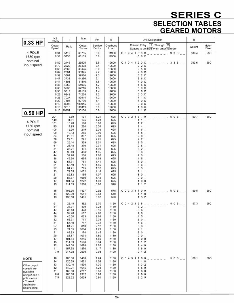
SELECTION TABLESGEARED MOTORS
0.34 5112 60755 0.9 11900 C 0 9 4 1 5 0 C _ _ _ _ _ _ . 3 3 B _ _ 509.4 56C 0.31 5733 68135 0.8 11900 5 6 C
0.82 2146 25505 3.6 19600 C 1 0 4 1 2 0 C _ _ _ _ _ _ . 3 3 B _ _ 793.6 56C 0.79 2222 26408 3.4 19600 2 2 C 0.68 2560 30425 3.0 19600 2 5 C 0.62 2804 33325 2.7 19600 2 8 C 0.52 3364 39980 2.3 19600 3 2 C 0.47 3733 44366 2.1 19600 3 6 C 0.41 4301 51116 1.8 19600 4 0 C 0.38 4550 54075 1.7 19600 4 5 C 0.33 5235 62216 1.5 19600 5 0 C 0.30 5817 69133 1.4 19600 5 6 C 0.28 6249 74268 1.2 19600 6 3 C 0.25 7027 83514 1.2 19600 7 1 C 0.22 7808 92796 1.1 19600 8 0 C 0.19 8996 106915 0.9 19600 9 0 C 0.18 9518 113119 0.9 19600 1 0 K 0.16 10951 130150 0.8 19600 1 1 K
201 8.59 131 5.21 625 C 0 3 2 1 8 . 0 _ _ _ _ _ _ . 5 0 B _ _ 50.7 56C 149 11.61 175 4.23 625 1 1 . 131 13.20 198 3.86 625 1 2 . 115 14.95 224 3.54 625 1 4 . 105 16.36 219 3.36 625 1 6 . 90 19.13 285 2.96 625 1 8 . 84 20.61 307 2.80 625 2 0 . 78 22.11 291 2.75 625 2 2 . 69 25.14 329 2.51 625 2 5 . 61 28.48 370 2.31 625 2 8 . 51 33.71 491 1.96 625 3 2 . 47 36.43 466 1.95 625 3 6 . 44 39.26 500 1.86 625 4 0 . 38 45.50 655 1.58 625 4 5 . 32 53.31 761 1.41 625 5 0 . 31 56.19 701 1.45 625 5 6 . 27 64.21 795 1.32 625 6 3 . 23 74.55 1052 1.16 625 7 1 . 21 82.83 1165 1.07 625 8 0 . 20 86.67 1050 1.12 625 9 0 . 17 101.54 1222 1.00 625 1 0 0 15 114.33 1586 0.86 540 1 1 2
16 105.36 1437 0.92 575 C 0 3 3 1 1 0 0 _ _ _ _ _ _ . 5 0 B _ _ 59.5 56C 14 120.39 1641 0.83 540 1 1 8 13 130.10 1491 0.82 520 1 3 2
61 28.48 382 3.70 1180 C 0 4 2 1 2 8 . _ _ _ _ _ _ . 5 0 B _ _ 57.3 56C 51 33.71 499 3.28 1180 3 2 . 47 36.43 478 3.15 1180 3 6 . 44 39.26 517 2.96 1180 4 0 . 38 45.50 663 2.64 1180 4 5 . 32 53.31 771 2.35 1180 5 0 . 31 56.19 717 2.32 1180 5 6 . 27 64.21 810 2.12 1180 6 3 . 23 74.55 1064 1.73 1180 7 1 . 21 82.83 1174 1.45 1180 8 0 . 20 86.67 1074 1.80 1180 9 0 . 17 101.54 1245 1.60 1180 1 0 0 15 114.33 1598 0.94 1180 1 1 2 12 142.00 1698 1.26 1180 1 4 0 11 157.78 1870 1.17 1180 1 6 0 7.9 217.78 2539 0.93 1120 2 1 2
16 105.36 1460 1.24 1180 C 0 4 3 1 1 0 0 _ _ _ _ _ _ . 5 0 B _ _ 66.1 56C 14 120.39 1661 1.09 1180 1 1 8 13 130.10 1530 1.30 1180 1 3 2 12 140.21 1645 1.24 1180 1 5 0 11 162.50 2217 0.81 1180 1 6 0 8.6 200.68 2312 0.99 1180 2 0 0 7.5 229.32 2629 0.91 1180 2 2 5
4 POLE1750 rpm nominal
input speed
0.33 HP
4 POLE1750 rpm nominal
input speed
0.50 HP

SERIES C
25
N2 R/MIN i lb.in Fm lb lb
OutputSpeed Ratio Output
TorqueServiceFactor
OverhungLoad
Unit Designation
Weight MotorSize
Column Entry 1 Through 20 Spacestobefilledwhenenteringorder
NOTE
Other output speeds are available using 2 and 6 pole motors - Consult Application Engineering
SERIES C
25
SELECTION TABLESGEARED MOTORS
24 73.37 1076 2.96 1650 C 0 5 2 1 7 1 . _ _ _ _ _ _ . 5 0 B _ _ 61.7 56C 21 82.67 1206 2.67 1650 8 0 . 19 90.67 1161 3.54 1650 9 0 . 18 98.57 1254 3.33 1650 1 0 0 16 109.07 1571 1.94 1650 1 1 2 14 124.00 1772 1.48 1650 1 2 5 12 142.00 1761 2.54 1650 1 4 0 11 160.00 1969 2.32 1650 1 6 0 8.2 211.11 2555 1.89 1650 2 1 2 7.2 240.00 2876 1.48 1650 2 5 0
17 103.90 1486 2.41 1650 C 0 5 3 1 1 0 0 _ _ _ _ _ _ . 5 0 B _ _ 68.3 56C 15 118.73 1690 2.10 1650 1 1 8 13 130.38 1608 2.57 1650 1 3 2 12 140.51 1724 2.45 1650 1 5 0 11 160.26 2254 1.56 1650 1 6 0 9.2 187.76 2625 1.34 1650 1 8 0 8.6 201.10 2415 1.95 1650 2 0 0 7.5 229.81 2738 1.79 1650 2 2 5 6.6 262.58 3616 0.96 1650 2 6 5 5.9 291.75 4005 0.86 1650 2 8 0 5.6 310.18 3634 1.42 1650 3 1 5 4.7 363.40 4220 1.25 1650 3 6 0 16 110.57 1680 3.97 2580 C 0 6 2 1 1 1 2 _ _ _ _ _ _ . 5 0 B _ _ 92.5 56C 14 124.00 1872 2.52 2580 1 2 5 12 143.08 1888 3.97 2580 1 4 0 11 156.67 2062 3.65 2580 1 6 0 8.1 214.00 2736 2.75 2580 2 1 2 7.2 240.00 3046 2.47 2580 2 5 0
13 130.00 1702 3.99 2580 C 0 6 3 1 1 3 2 _ _ _ _ _ _ . 5 0 B _ _ 103.6 56C 12 147.69 1921 3.67 2580 1 5 0 10 169.81 2522 3.07 2580 1 6 0 9.3 184.62 2725 2.83 2580 1 8 0 8.6 201.02 2569 3.01 2580 2 0 0 7.6 228.38 2898 2.78 2580 2 2 5 6.5 265.95 3889 1.96 2580 2 6 5 5.8 299.67 4363 1.74 2580 2 8 0 5.2 328.67 4061 2.11 2580 3 1 5 4.8 357.32 4391 1.95 2580 3 6 0 4.4 395.39 5716 1.32 2580 4 0 0 3.8 449.50 6459 1.16 2580 4 5 0 3.4 514.75 6172 1.39 2580 5 0 0 3.0 580.00 6909 1.24 2580 5 6 0 2.3 765.28 8977 0.95 2580 8 0 0 2.0 870.00 10127 0.85 2200 9 0 0
8.3 208.65 3033 3.38 6050 C 0 7 2 1 2 1 2 _ _ _ _ _ _ . 5 0 B _ _ 189.5 56C 7.4 231.83 3376 3.09 6050 2 5 0
8.9 194.65 2830 3.60 6050 C 0 7 3 1 2 0 0 _ _ _ _ _ _ . 5 0 B _ _ 211.6 56C 7.6 226.39 3264 3.20 6050 2 2 5 6.9 249.94 3822 3.17 6050 2 6 5 6.3 273.68 4169 2.91 6050 2 8 0 5.4 319.95 4573 2.42 6050 3 1 5 5.0 341.61 4865 2.29 6050 3 6 0 4.6 373.83 5641 2.15 6050 4 0 0 4.1 419.25 6300 1.92 6050 4 5 0 3.5 499.88 7004 1.60 6050 5 0 0 3.2 547.35 7647 1.47 6050 5 6 0 2.3 747.66 10263 1.09 6050 8 0 0 2.1 838.50 11462 0.97 6050 9 0 0
1.73 1009 18173 0.8 6050 C 0 7 4 1 1 0 C _ _ _ _ _ _ . 5 0 B _ _ 222.6 56C
4 POLE1750 rpm nominal
input speed
0.50 HP

SERIES C
26
N2 R/MIN i lb.in Fm lb lb
OutputSpeed Ratio Output
TorqueServiceFactor
OverhungLoad
Unit Designation
Weight MotorSize
Column Entry 1 Through 20 Spacestobefilledwhenenteringorder
NOTE
Other output speeds are available using 2 and 6 pole motors - Consult Application Engineering
26
SELECTION TABLESGEARED MOTORS
201 8.59 197 3.47 625 C 0 3 2 1 8 . 0 _ _ _ _ _ _ . 7 5 B _ _ 53.7 56C 149 11.61 263 2.82 625 1 1 . 131 13.20 297 2.57 625 1 2 . 115 14.95 336 2.36 625 1 4 . 105 16.36 328 2.24 625 1 6 . 90 19.13 427 1.97 625 1 8 . 84 20.61 460 1.87 625 2 0 . 78 22.11 436 1.83 625 2 2 . 69 25.14 493 1.68 625 2 5 . 61 28.48 556 1.54 625 2 8 . 51 33.71 736 1.31 625 3 2 . 47 36.43 699 1.30 625 3 6 . 44 39.26 750 1.24 625 4 0 . 38 45.50 982 1.05 625 4 5 . 32 53.31 1142 0.94 625 5 0 . 31 56.19 1051 0.97 625 5 6 . 27 64.21 1192 0.88 550 6 3 .
3.20 547 9850 2.9 9380 C 0 8 4 1 5 6 0 _ _ _ _ _ _ . 5 0 B _ _ 350.5 56C 2.75 636 11453 2.5 9380 6 3 0 2.46 712 12821 2.2 9380 7 1 0 2.31 759 13667 2.1 9380 8 0 0 1.95 899 16188 1.8 9380 9 0 0 1.82 960 17287 1.6 9380 1 0 C 1.61 1084 19520 1.5 9380 1 1 C 1.47 1191 21447 1.3 9380 1 2 C 1.25 1405 25300 1.1 9380 1 4 C 1.14 1532 27587 1.0 9380 1 6 C 0.92 1901 34232 0.8 9380 1 8 C 0.84 2088 37599 0.8 9380 2 0 C
2.26 774 13938 3.7 11900 C 0 9 4 1 8 0 0 _ _ _ _ _ _ . 5 0 B _ _ 511.4 56C 1.91 918 16531 3.1 11900 9 0 0 1.79 980 17647 2.9 11900 1 0 C 1.61 1089 19610 2.7 11900 1 1 C 1.44 1216 21897 2.4 11900 1 2 C 1.22 1434 25822 2.0 11900 1 4 C 1.14 1538 27695 1.9 11900 1 6 C 0.92 1908 34358 1.5 11900 1 8 C 0.83 2107 37941 1.4 11900 2 0 C 0.78 2250 40516 1.3 11900 2 2 C 0.70 2484 44730 1.2 11900 2 5 C 0.64 2720 48979 1.1 11900 2 8 C 0.52 3334 60036 0.9 11900 3 2 C 0.46 3775 67977 0.8 11900 3 6 C
1.25 1402 25246 3.5 19600 C 1 0 4 1 1 4 C _ _ _ _ _ _ . 5 0 B _ _ 793.6 56C 1.09 1607 28937 3.1 19600 1 6 C 0.94 1863 33547 2.7 19600 1 8 C 0.82 2146 38643 2.4 19600 2 0 C 0.79 2222 40012 2.3 19600 2 2 C 0.68 2560 46098 2.0 19600 2 5 C 0.62 2804 50492 1.8 19600 2 8 C 0.52 3364 60576 1.5 19600 3 2 C 0.47 3733 67221 1.4 19600 3 6 C 0.41 4301 77449 1.2 19600 4 0 C 0.38 4550 81933 1.2 19600 4 5 C 0.33 5235 94267 1.0 19600 5 0 C 0.30 5817 104748 0.9 19600 5 6 C 0.28 6249 112527 0.8 19600 6 3 C 0.25 7027 126536 0.8 19600 7 1 C
4 POLE1750 rpm nominal
input speed
0.50 HP
4 POLE1750 rpm nominal
input speed
0.75 HP

SERIES C
27
N2 R/MIN i lb.in Fm lb lb
OutputSpeed Ratio Output
TorqueServiceFactor
OverhungLoad
Unit Designation
Weight MotorSize
Column Entry 1 Through 20 Spacestobefilledwhenenteringorder
NOTE
Other output speeds are available using 2 and 6 pole motors - Consult Application Engineering
SERIES C
27
SELECTION TABLESGEARED MOTORS
115 14.95 344 3.93 1180 C 0 4 2 1 1 4 . _ _ _ _ _ _ . 7 5 B _ _ 60.3 56C 105 16.36 338 3.58 1180 1 6 . 90 19.13 437 3.28 1180 1 8 . 84 20.61 468 3.12 1180 2 0 . 78 22.11 450 2.93 1180 2 2 . 69 25.14 508 2.68 1180 2 5 . 61 28.48 573 2.47 1180 2 8 . 51 33.71 749 2.19 1180 3 2 . 47 36.43 717 2.10 1180 3 6 . 44 39.26 775 1.97 1180 4 0 . 38 45.50 995 1.76 1180 4 5 . 32 53.31 1157 1.57 1180 5 0 . 31 56.19 1076 1.55 1180 5 6 . 27 64.21 1216 1.41 1180 6 3 . 23 74.55 1597 1.15 1180 7 1 . 21 82.83 1762 0.97 1180 8 0 . 20 86.67 1612 1.20 1180 9 0 . 17 101.54 1867 1.07 1180 1 0 0 12 142.00 2547 0.84 990 1 4 0
16 105.36 2190 0.83 990 C 0 4 3 1 1 0 0 _ _ _ _ _ _ . 7 5 B _ _ 69.1 56C 13 130.10 2295 0.86 990 1 3 2 12 140.21 2467 0.82 990 1 5 0
53 32.55 740 3.79 1650 C 0 5 2 1 3 2 . _ _ _ _ _ _ . 7 5 B _ _ 64.7 56C 37 46.84 1050 2.91 1650 4 5 . 34 50.93 1137 2.73 1650 5 0 . 31 55.45 1102 3.24 1650 5 6 . 27 63.00 1240 2.93 1650 6 3 . 24 73.37 1614 1.97 1650 7 1 . 21 82.67 1809 1.78 1650 8 0 . 19 90.67 1742 2.36 1650 9 0 . 18 98.57 1881 2.22 1650 1 0 0 16 109.07 2357 1.30 1650 1 1 2 14 124.00 2658 0.99 1650 1 2 5 12 142.00 2641 1.69 1650 1 4 0 11 160.00 2953 1.55 1650 1 6 0 8.2 211.11 3833 1.26 1650 2 1 2 7.2 240.00 4314 0.99 1650 2 5 0 17 103.90 2229 1.60 1650 C 0 5 3 1 1 0 0 _ _ _ _ _ _ . 7 5 B _ _ 71.3 56C 15 118.73 2536 1.40 1650 1 1 8 13 130.38 2412 1.71 1650 1 3 2 12 140.51 2586 1.63 1650 1 5 0 11 160.26 3381 1.04 1650 1 6 0 9.2 187.76 3937 0.89 1650 1 8 0 8.6 201.10 3623 1.30 1650 2 0 0 7.5 229.81 4108 1.19 1650 2 2 5 5.6 310.18 5451 0.95 1600 3 1 5
23 73.92 1713 3.72 2580 C 0 6 2 1 7 1 . _ _ _ _ _ _ . 7 5 B _ _ 94.5 56C 21 80.94 1869 3.44 2580 8 0 . 19 91.58 1875 3.67 2580 9 0 . 18 97.78 1985 3.51 2580 1 0 0 16 110.57 2520 2.64 2580 1 1 2 14 124.00 2808 1.68 2580 1 2 5 12 143.08 2832 2.64 2580 1 4 0 11 156.67 3093 2.43 2580 1 6 0 8.1 214.00 4104 1.83 2580 2 1 2 7.2 240.00 4570 1.65 2580 2 5 0
4 POLE1750 rpm nominal
input speed
0.75 HP

SERIES C
28
N2 R/MIN i lb.in Fm lb lb
OutputSpeed Ratio Output
TorqueServiceFactor
OverhungLoad
Unit Designation
Weight MotorSize
Column Entry 1 Through 20 Spacestobefilledwhenenteringorder
NOTE
Other output speeds are available using 2 and 6 pole motors - Consult Application Engineering
28
SELECTION TABLESGEARED MOTORS
17 103.86 2355 3.08 2580 C 0 6 3 1 1 0 0 _ _ _ _ _ _ . 7 5 B _ _ 106.6 56C 15 117.99 2675 2.80 2580 1 1 8 13 130.00 2554 2.66 2580 1 3 2 12 147.69 2882 2.45 2580 1 5 0 10 169.81 3783 2.04 2580 1 6 0 9.3 184.62 4087 1.89 2580 1 8 0 8.6 201.02 3854 2.01 2580 2 0 0 7.6 228.38 4347 1.85 2580 2 2 5 5.8 299.67 6545 1.16 2580 2 8 0 5.2 328.67 6091 1.41 2580 3 1 5 4.8 357.32 6586 1.30 2580 3 6 0 4.4 395.39 8574 0.88 2270 4 0 0 3.4 514.75 9259 0.93 2400 5 0 0 3.0 580.00 10364 0.83 2100 5 6 0
17 99.79 2276 3.97 6050 C 0 7 2 1 1 0 0 _ _ _ _ _ _ . 7 5 B _ _ 192.5 56C 17 104.32 2459 3.30 6050 1 1 2 15 115.92 2726 2.96 6050 1 2 5 13 138.00 3099 3.08 6050 1 4 0 11 151.13 3368 2.89 6050 1 6 0 8.3 208.65 4550 2.26 6050 2 1 2 7.4 231.83 5064 2.06 6050 2 5 0 11 159.98 3718 3.26 6050 C 0 7 3 1 1 6 0 _ _ _ _ _ _ . 7 5 B _ _ 214.6 56C 10 170.81 3976 3.05 6050 1 8 0 8.9 194.65 4246 2.40 6050 2 0 0 7.6 226.39 4897 2.13 6050 2 2 5 6.9 249.94 5733 2.11 6050 2 6 5 6.3 273.68 6254 1.94 6050 2 8 0 5.4 319.95 6860 1.61 6050 3 1 5 5.0 341.61 7298 1.53 6050 3 6 0 4.6 373.83 8462 1.43 6050 4 0 0 4.1 419.25 9450 1.28 6050 4 5 0 3.5 499.88 10506 1.07 6050 5 0 0 3.2 547.35 11470 0.98 6050 5 6 0
3.20 547 14775 1.9 9380 C 0 8 4 1 5 6 0 _ _ _ _ _ _ . 7 5 B _ _ 353.5 56C 2.75 636 17179 1.7 9380 6 3 0 2.46 712 19232 1.5 9380 7 1 0 2.31 759 20501 1.4 9380 8 0 0 1.95 899 24283 1.2 9380 9 0 0 1.82 960 25930 1.1 9380 1 0 C 1.61 1084 29280 1.0 9380 1 1 C 1.47 1191 32170 0.9 9380 1 2 C
3.14 558 15072 3.4 11900 C 0 9 4 1 5 6 0 _ _ _ _ _ _ . 7 5 B _ _ 514.4 56C 2.70 649 17530 2.9 11900 6 3 0 2.41 727 19637 2.6 11900 7 1 0 2.26 774 20906 2.5 11900 8 0 0 1.91 918 24796 2.1 11900 9 0 0 1.79 980 26471 1.9 11900 1 0 C 1.61 1089 29415 1.8 11900 1 1 C 1.44 1216 32845 1.6 11900 1 2 C 1.22 1434 38733 1.3 11900 1 4 C 1.14 1538 41542 1.3 11900 1 6 C 0.92 1908 51536 1.0 11900 1 8 C 0.83 2107 56912 0.9 11900 2 0 C 0.78 2250 60774 0.9 11900 2 2 C 0.70 2484 67095 0.8 11900 2 5 C
4 POLE1750 rpm nominal
input speed
0.75 HP

SERIES C
29
N2 R/MIN i lb.in Fm lb lb
OutputSpeed Ratio Output
TorqueServiceFactor
OverhungLoad
Unit Designation
Weight MotorSize
Column Entry 1 Through 20 Spacestobefilledwhenenteringorder
NOTE
Other output speeds are available using 2 and 6 pole motors - Consult Application Engineering
SERIES C
29
SELECTION TABLESGEARED MOTORS
1.95 897 24229 3.7 19600 C 1 0 4 1 9 0 0 _ _ _ _ _ _ . 7 5 B _ _ 796.6 56C 1.73 1014 27389 3.2 19600 1 0 C 1.55 1127 30441 2.9 19600 1 1 C 1.49 1176 31765 2.8 19600 1 2 C 1.25 1402 37869 2.3 19600 1 4 C 1.09 1607 43406 2.1 19600 1 6 C 0.94 1863 50321 1.8 19600 1 8 C 0.82 2146 57965 1.6 19600 2 0 C 0.79 2222 60018 1.5 19600 2 2 C 0.68 2560 69147 1.3 19600 2 5 C 0.62 2804 75738 1.2 19600 2 8 C 0.52 3364 90864 1.0 19600 3 2 C 0.47 3733 100831 0.9 19600 3 6 C 0.41 4301 116173 0.8 19600 4 0 C 0.38 4550 122899 0.8 19600 4 5 C
201 8.59 263 2.60 625 C 0 3 2 1 8 . 0 _ _ _ _ _ _ 1 . 0 B _ _ 58.7 143TC 149 11.61 351 2.11 625 1 1 . 131 13.20 397 1.93 625 1 2 . 115 14.95 448 1.77 625 1 4 . 105 16.36 438 1.68 625 1 6 . 90 19.13 570 1.48 625 1 8 . 84 20.61 614 1.40 625 2 0 . 78 22.11 582 1.37 625 2 2 . 69 25.14 658 1.26 625 2 5 . 61 28.48 741 1.16 625 2 8 . 51 33.71 982 0.98 625 3 2 . 47 36.43 933 0.98 625 3 6 . 44 39.26 1000 0.93 581 4 0 .
149 11.61 359 3.52 1180 C 0 4 2 1 1 1 . _ _ _ _ _ _ 1 . 0 B _ _ 65.3 143TC 131 13.20 406 3.20 1180 1 2 . 115 14.95 459 2.95 1180 1 4 . 105 16.36 451 2.68 1180 1 6 . 90 19.13 583 2.46 1180 1 8 . 84 20.61 624 2.34 1180 2 0 . 78 22.11 600 2.19 1180 2 2 . 69 25.14 678 2.01 1180 2 5 . 61 28.48 765 1.85 1180 2 8 . 51 33.71 998 1.64 1180 3 2 . 47 36.43 956 1.57 1180 3 6 . 44 39.26 1034 1.48 1180 4 0 . 38 45.50 1327 1.32 1180 4 5 . 32 53.31 1543 1.18 1180 5 0 . 31 56.19 1435 1.16 1180 5 6 . 27 64.21 1621 1.06 1180 6 3 . 23 74.55 2129 0.86 1050 7 1 . 20 86.67 2149 0.90 1060 9 0 .
82 21.05 648 3.77 1650 C 0 5 2 1 2 0 . _ _ _ _ _ _ 1 . 0 B _ _ 69.7 143TC 61 28.24 785 3.97 1650 2 8 . 53 32.55 987 2.84 1650 3 2 . 48 35.86 981 3.34 1650 3 6 . 42 40.74 1105 3.03 1650 4 0 . 37 46.84 1400 2.18 1650 4 5 . 34 50.93 1516 2.05 1650 5 0 . 31 55.45 1470 2.43 1650 5 6 . 27 63.00 1653 2.22 1650 6 3 . 24 73.37 2152 1.48 1650 7 1 . 21 82.67 2413 1.34 1650 8 0 . 19 90.67 2323 1.77 1650 9 0 . 18 98.57 2508 1.67 1650 1 0 0 16 109.07 3142 0.97 1650 1 1 2 12 142.00 3522 1.27 1650 1 4 0 11 160.00 3938 1.16 1650 1 6 0 8.2 211.11 5110 0.94 1550 2 1 2
17 103.90 2972 1.20 1650 C 0 5 3 1 1 0 0 _ _ _ _ _ _ 1 . 0 B _ _ 76.3 143TC 15 118.73 3381 1.05 1650 1 1 8 13 130.38 3216 1.28 1650 1 3 2 12 140.51 3449 1.22 1650 1 5 0 8.6 201.10 4830 0.97 1650 2 0 0
4 POLE1750 rpm nominal
input speed
0.75 HP
4 POLE1750 rpm nominal
input speed
1 HP

SERIES C
30
N2 R/MIN i lb.in Fm lb lb
OutputSpeed Ratio Output
TorqueServiceFactor
OverhungLoad
Unit Designation
Weight MotorSize
Column Entry 1 Through 20 Spacestobefilledwhenenteringorder
NOTE
Other output speeds are available using 2 and 6 pole motors - Consult Application Engineering
30
SELECTION TABLESGEARED MOTORS
36 47.32 1488 3.90 2580 C 0 6 2 1 4 5 . _ _ _ _ _ _ 1 . 0 B _ _ 100.5 143TC 34 50.52 1585 3.74 2580 5 0 . 31 55.71 1570 3.79 2580 5 6 . 27 64.80 1806 3.41 2580 6 3 . 23 73.92 2284 2.79 2580 7 1 . 21 80.94 2492 2.58 2580 8 0 . 19 91.58 2501 2.75 2580 9 0 . 18 97.78 2647 2.63 2580 1 0 0 16 110.57 3361 1.98 2580 1 1 2 14 124.00 3744 1.26 2580 1 2 5 12 143.08 3776 1.98 2580 1 4 0 11 156.67 4124 1.82 2580 1 6 0 8.1 214.00 5472 1.37 2580 2 1 2 7.2 240.00 6093 1.23 2580 2 5 0
17 103.86 3141 2.31 2580 C 0 6 3 1 1 0 0 _ _ _ _ _ _ 1 . 0 B _ _ 111.6 143TC 15 117.99 3566 2.10 2580 1 1 8 13 130.00 3405 2.00 2580 1 3 2 12 147.69 3843 1.84 2580 1 5 0 10 169.81 5044 1.53 2580 1 6 0 9.3 184.62 5450 1.41 2580 1 8 0 8.6 201.02 5139 1.51 2580 2 0 0 7.6 228.38 5796 1.39 2580 2 2 5 6.5 265.95 7778 0.98 2580 2 6 5 5.8 299.67 8727 0.87 2580 2 8 0 5.2 328.67 8122 1.05 2580 3 1 5 4.8 357.32 8782 0.98 2580 3 6 0
25 69.00 2210 3.50 6050 C 0 7 2 1 7 1 . _ _ _ _ _ _ 1 . 0 B _ _ 197.5 143TC 23 75.56 2413 3.24 6050 8 0 . 20 88.26 2694 3.28 6050 9 0 . 17 99.79 3035 2.97 6050 1 0 0 17 104.32 3279 2.47 6050 1 1 2 15 115.92 3634 2.22 6050 1 2 5 13 138.00 4132 2.31 6050 1 4 0 11 151.13 4490 2.17 6050 1 6 0 8.3 208.65 6067 1.69 6050 2 1 2 7.4 231.83 6752 1.55 6050 2 5 0
18 97.33 3067 3.95 6050 C 0 7 3 1 1 0 0 _ _ _ _ _ _ 1 . 0 B _ _ 219.6 143TC 15 113.20 3555 3.41 6050 1 1 8 11 159.98 4958 2.45 6050 1 6 0 10 170.81 5302 2.29 6050 1 8 0 8.9 194.65 5661 1.80 6050 2 0 0 7.6 226.39 6529 1.60 6050 2 2 5 6.9 249.94 7644 1.59 6050 2 6 5 6.3 273.68 8339 1.45 6050 2 8 0 5.4 319.95 9147 1.21 6050 3 1 5 5.0 341.61 9730 1.15 6050 3 6 0 4.6 373.83 11282 1.07 6050 4 0 0 4.1 419.25 12600 0.96 5900 4 5 0 3.5 499.88 14009 0.80 4840 5 0 0
8.4 204.75 6084 3.48 9380 C 0 8 2 1 2 1 2 _ _ _ _ _ _ 1 . 0 B _ _ 316.6 143TC 7.3 235.77 6951 3.12 9380 2 5 0
3.20 547 19700 1.4 9380 C 0 8 4 1 5 6 0 _ _ _ _ _ _ 1 . 0 B _ _ 358.6 143TC 2.75 636 22905 1.2 9380 6 3 0 2.46 712 25642 1.1 9380 7 1 0 2.31 759 27335 1.0 9380 8 0 0 1.95 899 32377 0.9 8450 9 0 0 1.82 960 34574 0.8 7504 1 0 C
4 POLE1750 rpm nominal
input speed
1 HP

SERIES C
31
N2 R/MIN i lb.in Fm lb lb
OutputSpeed Ratio Output
TorqueServiceFactor
OverhungLoad
Unit Designation
Weight MotorSize
Column Entry 1 Through 20 Spacestobefilledwhenenteringorder
NOTE
Other output speeds are available using 2 and 6 pole motors - Consult Application Engineering
SERIES C
31
SELECTION TABLESGEARED MOTORS
3.14 558 20096 2.6 11900 C 0 9 4 1 5 6 0 _ _ _ _ _ _ 1 . 0 B _ _ 519.4 143TC 2.70 649 23373 2.2 11900 6 3 0 2.41 727 26182 2.0 11900 7 1 0 2.26 774 27875 1.9 11900 8 0 0 1.91 918 33061 1.6 11900 9 0 0 1.79 980 35294 1.5 11900 1 0 C 1.61 1089 39220 1.3 11900 1 1 C 1.44 1216 43793 1.2 11900 1 2 C 1.22 1434 51644 1.0 11900 1 4 C 1.14 1538 55390 0.9 11900 1 6 C 0.92 1908 68715 0.8 11900 1 8 C 2.80 626 22545 3.9 19600 C 1 0 4 1 6 3 0 _ _ _ _ _ _ 1 . 0 B _ _ 801.6 143TC 2.46 710 25570 3.5 19600 7 1 0 2.23 783 28199 3.2 19600 8 0 0 1.95 897 32305 2.8 19600 9 0 0 1.73 1014 36518 2.4 19600 1 0 C 1.55 1127 40588 2.1 19600 1 1 C 1.49 1176 42353 2.1 19600 1 2 C 1.25 1402 50492 1.8 19600 1 4 C 1.09 1607 57875 1.6 19600 1 6 C 0.94 1863 67095 1.4 19600 1 8 C 0.82 2146 77287 1.2 19600 2 0 C 0.79 2222 80024 1.1 19600 2 2 C 0.68 2560 92197 1.0 19600 2 5 C 0.62 2804 100984 0.9 19600 2 8 C 0.52 3364 121152 0.8 19600 3 2 C
201 8.59 394 1.74 625 C 0 3 2 1 8 . 0 _ _ _ _ _ _ 1 . 5 B _ _ 62.7 145TC 149 11.61 527 1.41 625 1 1 . 131 13.20 595 1.29 625 1 2 . 115 14.95 672 1.18 625 1 4 . 105 16.36 657 1.12 625 1 6 . 90 19.13 855 0.99 625 1 8 . 84 20.61 921 0.93 575 2 0 . 78 22.11 873 0.92 575 2 2 . 69 25.14 987 0.84 525 2 5 .
201 8.59 402 2.88 1180 C 0 4 2 1 8 . 0 _ _ _ _ _ _ 1 . 5 B _ _ 69.3 145TC 149 11.61 539 2.34 1180 1 1 . 131 13.20 610 2.13 1180 1 2 . 115 14.95 689 1.97 1180 1 4 . 105 16.36 677 1.79 1180 1 6 . 90 19.13 874 1.64 1180 1 8 . 84 20.61 936 1.56 1180 2 0 . 78 22.11 901 1.46 1180 2 2 . 69 25.14 1017 1.34 1180 2 5 . 61 28.48 1147 1.23 1180 2 8 . 51 33.71 1498 1.09 1180 3 2 . 47 36.43 1434 1.05 1180 3 6 . 44 39.26 1551 0.99 1180 4 0 . 38 45.50 1990 0.88 1040 4 5 .
148 11.66 553 3.55 1650 C 0 5 2 1 1 1 . _ _ _ _ _ _ 1 . 5 B _ _ 73.7 145TC 134 12.85 604 3.37 1650 1 2 . 118 14.59 684 3.13 1650 1 4 . 107 16.09 697 3.90 1650 1 6 . 93 18.53 860 2.71 1650 1 8 . 82 21.05 972 2.51 1650 2 0 . 76 22.56 958 3.09 1650 2 2 . 69 24.86 1047 2.89 1650 2 5 . 61 28.24 1178 2.64 1650 2 8 . 53 32.55 1480 1.89 1650 3 2 . 48 35.86 1472 2.23 1650 3 6 . 42 40.74 1657 2.02 1650 4 0 . 37 46.84 2100 1.45 1650 4 5 . 34 50.93 2274 1.37 1650 5 0 . 31 55.45 2205 1.62 1650 5 6 . 27 63.00 2480 1.48 1650 6 3 . 24 73.37 3228 0.99 1650 7 1 . 21 82.67 3619 0.89 1650 8 0 . 19 90.67 3485 1.18 1650 9 0 . 18 98.57 3762 1.11 1650 1 0 0 12 142.00 5283 0.85 1402 1 4 0
4 POLE1750 rpm nominal
input speed
1 HP
4 POLE1750 rpm nominal
input speed
1.5 HP

SERIES C
32
N2 R/MIN i lb.in Fm lb lb
OutputSpeed Ratio Output
TorqueServiceFactor
OverhungLoad
Unit Designation
Weight MotorSize
Column Entry 1 Through 20 Spacestobefilledwhenenteringorder
NOTE
Other output speeds are available using 2 and 6 pole motors - Consult Application Engineering
32
SELECTION TABLESGEARED MOTORS
17 103.90 4458 0.80 1650 C 0 5 3 1 1 0 0 _ _ _ _ _ _ 1 . 5 B _ _ 80.3 145TC 13 130.38 4825 0.86 1650 1 3 2 12 140.51 5173 0.82 1350 1 5 0 52 33.48 1600 3.23 2580 C 0 6 2 1 3 2 . _ _ _ _ _ _ 1 . 5 B _ _ 104.5 145TC 36 47.32 2233 2.60 2580 4 5 . 34 50.52 2377 2.49 2580 5 0 . 31 55.71 2355 2.53 2580 5 6 . 27 64.80 2709 2.27 2580 6 3 . 23 73.92 3427 1.86 2580 7 1 . 21 80.94 3739 1.72 2580 8 0 . 19 91.58 3751 1.83 2580 9 0 . 18 97.78 3971 1.75 2580 1 0 0 16 110.57 5041 1.32 2580 1 1 2 14 124.00 5617 0.84 2580 1 2 5 12 143.08 5664 1.32 2580 1 4 0 11 156.67 6186 1.22 2580 1 6 0 8.1 214.00 8208 0.92 2370 2 1 2 7.2 240.00 9140 0.82 2110 2 5 0
17 103.86 4711 1.54 2580 C 0 6 3 1 1 0 0 _ _ _ _ _ _ 1 . 5 B _ _ 115.6 145TC 15 117.99 5350 1.40 2580 1 1 8 13 130.00 5108 1.33 2580 1 3 2 12 147.69 5765 1.22 2580 1 5 0 10 169.81 7567 1.02 2580 1 6 0 9.3 184.62 8175 0.94 2580 1 8 0 8.6 201.02 7708 1.00 2580 2 0 0 7.6 228.38 8694 0.93 2580 2 2 5
39 44.13 2152 3.38 6050 C 0 7 2 1 4 5 . _ _ _ _ _ _ 1 . 5 B _ _ 201.5 145TC 35 49.90 2423 3.03 6050 5 0 . 32 53.63 2508 3.23 6050 5 6 . 28 61.62 2863 2.90 6050 6 3 . 25 69.00 3316 2.34 6050 7 1 . 23 75.56 3619 2.16 6050 8 0 . 20 88.26 4041 2.19 6050 9 0 . 17 99.79 4553 1.98 6050 1 0 0 17 104.32 4919 1.65 6050 1 1 2 15 115.92 5452 1.48 6050 1 2 5 13 138.00 6198 1.54 6050 1 4 0 11 151.13 6736 1.45 6050 1 6 0 8.3 208.65 9101 1.13 6050 2 1 2 7.4 231.83 10129 1.03 6050 2 5 0 18 97.33 4601 2.63 6050 C 0 7 3 1 1 0 0 _ _ _ _ _ _ 1 . 5 B _ _ 223.6 145TC 15 113.20 5333 2.27 6050 1 1 8 11 159.98 7437 1.63 6050 1 6 0 10 170.81 7953 1.52 6050 1 8 0 8.9 194.65 8492 1.20 6050 2 0 0 7.6 226.39 9794 1.07 6050 2 2 5 6.9 249.94 11466 1.06 6050 2 6 5 6.3 273.68 12508 0.97 6050 2 8 0 5.4 319.95 13720 0.81 4900 3 1 5
15 117.89 5602 3.89 9380 C 0 8 2 1 1 2 5 _ _ _ _ _ _ 1 . 5 B _ _ 320.6 145TC 12 139.29 6309 3.13 9380 1 4 0 11 153.00 6908 2.91 9380 1 6 0 8.4 204.75 9126 2.32 9380 2 1 2 7.3 235.77 10426 2.08 9380 2 5 0
3.20 547 29550 1.0 9380 C 0 8 4 1 5 6 0 _ _ _ _ _ _ 1 . 5 B _ _ 362.5 145TC 2.75 636 34358 0.8 9380 6 3 0
3.14 558 30144 1.7 11900 C 0 9 4 1 5 6 0 _ _ _ _ _ _ 1 . 5 B _ _ 523.5 145TC 2.70 649 35060 1.5 11900 6 3 0 2.41 727 39274 1.3 11900 7 1 0 2.26 774 41813 1.2 11900 8 0 0 1.91 918 49592 1.0 11900 9 0 0 1.79 980 52941 1.0 11900 1 0 C 1.61 1089 58829 0.9 11900 1 1 C 1.44 1216 65690 0.8 11900 1 2 C
4 POLE1750 rpm nominal
input speed
1.5 HP

SERIES C
33
N2 R/MIN i lb.in Fm lb lb
OutputSpeed Ratio Output
TorqueServiceFactor
OverhungLoad
Unit Designation
Weight MotorSize
Column Entry 1 Through 20 Spacestobefilledwhenenteringorder
NOTE
Other output speeds are available using 2 and 6 pole motors - Consult Application Engineering
SERIES C
33
SELECTION TABLESGEARED MOTORS
3.21 545 29442 3.0 19600 C 1 0 4 1 5 6 0 _ _ _ _ _ _ 1 . 5 B _ _ 805.6 145TC 2.80 626 33817 2.6 19600 6 3 0 2.46 710 38355 2.3 19600 7 1 0 2.23 783 42299 2.1 19600 8 0 0 1.95 897 48457 1.8 19600 9 0 0 1.73 1014 54778 1.6 19600 1 0 C 1.55 1127 60882 1.4 19600 1 1 C 1.49 1176 63529 1.4 19600 1 2 C 1.25 1402 75738 1.2 19600 1 4 C 1.09 1607 86812 1.0 19600 1 6 C 0.94 1863 100642 0.9 19600 1 8 C 0.82 2146 115930 0.8 19600 2 0 C 0.79 2222 120036 0.8 19600 2 2 C
201 8.59 526 1.30 625 C 0 3 2 1 8 . 0 _ _ _ _ _ _ 2 . 0 B _ _ 69.7 145TC 149 11.61 703 1.06 625 1 1 . 131 13.20 794 0.96 625 1 2 . 115 14.95 896 0.89 560 1 4 . 105 16.36 876 0.84 525 1 6 .
201 8.59 536 2.16 1180 C 0 4 2 1 8 . 0 _ _ _ _ _ _ 2 . 0 B _ _ 76.3 145TC 149 11.61 719 1.76 1180 1 1 . 131 13.20 813 1.60 1180 1 2 . 115 14.95 918 1.47 1180 1 4 . 105 16.36 903 1.34 1180 1 6 . 90 19.13 1166 1.23 1180 1 8 . 84 20.61 1248 1.17 1180 2 0 . 78 22.11 1201 1.10 1180 2 2 . 69 25.14 1356 1.00 1180 2 5 . 61 28.48 1530 0.93 1090 2 8 . 51 33.71 1997 0.82 960 3 2 .
208 8.31 530 3.22 1650 C 0 5 2 1 8 . 0 _ _ _ _ _ _ 2 . 0 B _ _ 80.7 145TC 148 11.66 737 2.66 1650 1 1 . 134 12.85 806 2.52 1650 1 2 . 118 14.59 912 2.35 1650 1 4 . 107 16.09 930 2.92 1650 1 6 . 93 18.53 1147 2.04 1650 1 8 . 82 21.05 1296 1.88 1650 2 0 . 76 22.56 1278 2.32 1650 2 2 . 69 24.86 1396 2.17 1650 2 5 . 61 28.24 1571 1.98 1650 2 8 . 53 32.55 1974 1.42 1650 3 2 . 48 35.86 1963 1.67 1650 3 6 . 42 40.74 2210 1.51 1650 4 0 . 37 46.84 2800 1.09 1650 4 5 . 34 50.93 3032 1.02 1650 5 0 . 31 55.45 2940 1.22 1650 5 6 . 27 63.00 3307 1.11 1650 6 3 . 19 90.67 4646 0.89 1486 9 0 . 18 98.57 5016 0.83 1370 1 0 0
52 33.48 2134 2.43 2580 C 0 6 2 1 3 2 . _ _ _ _ _ _ 2 . 0 B _ _ 111.5 145TC 36 47.32 2977 1.95 2580 4 5 . 34 50.52 3170 1.87 2580 5 0 . 31 55.71 3140 1.90 2580 5 6 . 27 64.80 3612 1.71 2580 6 3 . 23 73.92 4569 1.39 2580 7 1 . 21 80.94 4985 1.29 2580 8 0 . 19 91.58 5002 1.37 2580 9 0 . 18 97.78 5295 1.32 2580 1 0 0 16 110.57 6722 0.99 2580 1 1 2 12 143.08 7552 0.99 2580 1 4 0 11 156.67 8248 0.91 2322 1 6 0
17 103.86 6282 1.16 2580 C 0 6 3 1 1 0 0 _ _ _ _ _ _ 2 . 0 B _ _ 122.6 145TC 15 117.99 7133 1.05 2580 1 1 8 13 130.00 6810 1.00 2580 1 3 2 12 147.69 7687 0.92 2300 1 5 0
4 POLE1750 rpm nominal
input speed
1.5 HP
4 POLE1750 rpm nominal
input speed
2 HP

SERIES C
34
N2 R/MIN i lb.in Fm lb lb
OutputSpeed Ratio Output
TorqueServiceFactor
OverhungLoad
Unit Designation
Weight MotorSize
Column Entry 1 Through 20 Spacestobefilledwhenenteringorder
NOTE
Other output speeds are available using 2 and 6 pole motors - Consult Application Engineering
34
SELECTION TABLESGEARED MOTORS
56 30.81 2022 3.30 6050 C 0 7 2 1 3 2 . _ _ _ _ _ _ 2 . 0 B _ _ 208.5 145TC
39 44.13 2870 2.54 6050 C 0 7 2 1 4 5 . _ _ _ _ _ _ 2 . 0 B _ _ 208.5 145TC 35 49.90 3231 2.27 6050 5 0 . 32 53.63 3344 2.42 6050 5 6 . 28 61.62 3817 2.17 6050 6 3 . 25 69.00 4421 1.75 6050 7 1 . 23 75.56 4826 1.62 6050 8 0 . 20 88.26 5388 1.64 6050 9 0 . 17 99.79 6070 1.49 6050 1 0 0 17 104.32 6559 1.24 6050 1 1 2 15 115.92 7269 1.11 6050 1 2 5 13 138.00 8264 1.16 6050 1 4 0 11 151.13 8981 1.08 6050 1 6 0 18 97.33 6135 1.98 6050 C 0 7 3 1 1 0 0 _ _ _ _ _ _ 2 . 0 B _ _ 230.6 145TC 15 113.20 7110 1.71 6050 1 1 8 11 159.98 9916 1.22 6050 1 6 0 10 170.81 10604 1.14 6050 1 8 0 8.9 194.65 11323 0.90 5450 2 0 0
20 87.29 5409 3.37 9380 C 0 8 2 1 9 0 . _ _ _ _ _ _ 2 . 0 B _ _ 327.6 145TC 18 98.53 6060 3.07 9380 1 0 0 17 102.38 6534 3.56 9380 1 1 2 15 117.89 7469 2.91 9380 1 2 5 12 139.29 8412 2.35 9380 1 4 0
11 153.00 9211 2.18 9380 1 6 0 8.4 204.75 12169 1.74 9380 2 1 2 7.3 235.77 13902 1.56 9380 2 5 0
3.14 558 40192 1.3 11900 C 0 9 4 1 5 6 0 _ _ _ _ _ _ 2 . 0 B _ _ 530.4 145TC 2.70 649 46747 1.1 11900 6 3 0 2.41 727 52365 1.0 11900 7 1 0 2.26 774 55750 0.9 11900 8 0 0 1.91 918 66122 0.8 11900 9 0 0
3.21 545 39256 2.3 19600 C 1 0 4 1 5 6 0 _ _ _ _ _ _ 2 . 0 B _ _ 812.6 145TC 2.80 626 45090 2.0 19600 6 3 0 2.46 710 51140 1.7 19600 7 1 0 2.23 783 56398 1.6 19600 8 0 0 1.95 897 64610 1.4 19600 9 0 0 1.73 1014 73037 1.2 19600 1 0 C 1.55 1127 81176 1.1 19600 1 1 C 1.49 1176 84706 1.1 19600 1 2 C 1.25 1402 100984 0.9 19600 1 4 C 1.09 1607 115750 0.8 19600 1 6 C
4 POLE1750 rpm nominal
input speed
2 HP
4 POLE1750 rpm nominal
input speed
3 HP
201 8.59 789 0.87 545 C 0 3 2 1 8 . 0 _ _ _ _ _ _ 3 . 0 B _ _ 94.1 182TC 201 8.59 804 1.44 1180 C 0 4 2 1 8 . 0 _ _ _ _ _ _ 3 . 0 B _ _ 98.5 182TC 149 11.61 1079 1.17 1180 1 1 . 131 13.20 1220 1.07 1180 1 2 . 115 14.95 1378 0.98 1100 1 4 . 105 16.36 1355 0.89 1050 1 6 . 90 19.13 1749 0.82 965 1 8 .
208 8.31 796 2.15 1650 C 0 5 2 1 8 . 0 _ _ _ _ _ _ 3 . 0 B _ _ 102.9 182TC 148 11.66 1106 1.78 1650 1 1 . 134 12.85 1209 1.68 1650 1 2 . 118 14.59 1369 1.56 1650 1 4 . 107 16.09 1395 1.95 1650 1 6 . 93 18.53 1721 1.36 1650 1 8 . 82 21.05 1945 1.26 1650 2 0 . 76 22.56 1917 1.55 1650 2 2 . 69 24.86 2094 1.45 1650 2 5 . 61 28.24 2356 1.32 1650 2 8 . 53 32.55 2961 0.95 1650 3 2 . 48 35.86 2945 1.11 1650 3 6 . 42 40.74 3315 1.01 1650 4 0 . 31 55.45 4410 0.81 1330 5 6 .

SERIES C
35
N2 R/MIN i lb.in Fm lb lb
OutputSpeed Ratio Output
TorqueServiceFactor
OverhungLoad
Unit Designation
Weight MotorSize
Column Entry 1 Through 20 Spacestobefilledwhenenteringorder
NOTE
Other output speeds are available using 2 and 6 pole motors - Consult Application Engineering
SERIES C
35
SELECTION TABLESGEARED MOTORS
210 8.23 811 3.74 2580 C 0 6 2 1 8 . 0 _ _ _ _ _ _ 3 . 0 B _ _ 147.0 182TC 149 11.57 1137 3.08 2580 1 1 . 133 12.97 1274 2.88 2580 1 2 . 118 14.56 1426 2.69 2580 1 4 . 108 15.93 1435 2.97 2580 1 6 . 93 18.49 1800 2.34 2580 1 8 . 82 20.96 2033 2.16 2580 2 0 . 77 22.40 1994 2.44 2580 2 2 . 69 25.11 2222 2.28 2580 2 5 . 61 28.18 2477 2.10 2580 2 8 . 52 33.48 3201 1.62 2580 3 2 . 48 35.79 3110 1.77 2580 3 6 . 43 40.57 3498 1.60 2580 4 0 . 36 47.32 4466 1.30 2580 4 5 . 34 50.52 4755 1.25 2580 5 0 . 31 55.71 4710 1.26 2580 5 6 . 27 64.80 5418 1.14 2580 6 3 . 23 73.92 6854 0.93 2580 7 1 . 21 80.94 7478 0.86 2270 8 0 . 19 91.58 7503 0.92 2350 9 0 . 18 97.78 7943 0.88 2270 1 0 0
109 15.80 1526 3.94 6050 C 0 7 2 1 1 6 . _ _ _ _ _ _ 3 . 0 B _ _ 241.8 182TC 86 20.07 2006 3.79 6050 2 0 . 79 21.89 2102 3.13 6050 2 2 . 70 24.59 2359 2.88 6050 2 5 . 64 27.03 2584 2.69 6050 2 8 . 56 30.81 3033 2.20 6050 3 2 . 49 35.31 3355 2.21 6050 3 6 . 43 40.15 3792 2.01 6050 4 0 . 39 44.13 4305 1.69 6050 4 5 . 35 49.90 4846 1.52 6050 5 0 . 32 53.63 5016 1.61 6050 5 6 . 28 61.62 5726 1.45 6050 6 3 . 25 69.00 6632 1.17 6050 7 1 . 23 75.56 7239 1.08 6050 8 0 . 20 88.26 8083 1.09 6050 9 0 . 17 99.79 9106 0.99 6050 1 0 0 17 104.32 9839 0.82 4960 1 1 2
18 97.33 9203 1.32 6050 C 0 7 3 1 1 0 0 _ _ _ _ _ _ 3 . 0 B _ _ 266.0 182TC 15 113.20 10666 1.14 6050 1 1 8 14 125.04 11089 0.85 5200 1 3 2 11 159.98 14875 0.82 5000 1 6 0 35 49.26 4833 3.88 9380 C 0 8 2 1 5 0 . _ _ _ _ _ _ 3 . 0 B _ _ 347.6 182TC 32 54.60 5165 3.24 9380 5 6 . 27 63.56 5989 2.88 9380 6 3 . 25 69.64 6743 3.10 9380 7 1 . 23 76.50 7395 2.91 9380 8 0 . 20 87.29 8113 2.25 9380 9 0 . 18 98.53 9091 2.04 9380 1 0 0 17 102.38 9801 2.37 9380 1 1 2 15 117.89 11204 1.94 9380 1 2 5 12 139.29 12618 1.56 9380 1 4 0 11 153.00 13817 1.45 9380 1 6 0 8.4 204.75 18253 1.16 9380 2 1 2 7.3 235.77 20853 1.04 9380 2 5 0
11.22 156 16855 1.7 9380 C 0 8 4 1 1 6 0 _ _ _ _ _ _ 3 . 0 B _ _ 404.9 182TC 9.89 177 19124 1.5 9380 1 8 0 7.95 220 23769 1.2 9380 2 1 2 7.06 248 26795 1.1 9380 2 5 0 6.32 277 29928 0.9 9380 2 8 0 5.61 312 33709 0.8 9380 3 2 0
16 106.17 10291 3.75 11900 C 0 9 2 1 1 1 2 _ _ _ _ _ _ 3 . 0 B _ _ 488.7 182TC 14 119.38 11504 3.39 11900 1 2 5 12 146.23 13295 3.40 11900 1 4 0 11 161.44 14618 3.17 11900 1 6 0 7.8 222.08 19772 2.53 11900 2 1 2 6.9 249.73 22065 2.33 11900 2 5 0
4 POLE1750 rpm nominal
input speed
3 HP

SERIES C
36
N2 R/MIN i lb.in Fm lb lb
OutputSpeed Ratio Output
TorqueServiceFactor
OverhungLoad
Unit Designation
Weight MotorSize
Column Entry 1 Through 20 Spacestobefilledwhenenteringorder
NOTE
Other output speeds are available using 2 and 6 pole motors - Consult Application Engineering
36
SELECTION TABLESGEARED MOTORS
10.94 160 17287 3.0 11900 C 0 9 4 1 1 6 0 _ _ _ _ _ _ 3 . 0 B _ _ 574.7 182TC 9.89 177 19124 2.7 11900 1 8 0 7.78 225 24310 2.1 11900 2 1 2 7.03 249 26903 1.9 11900 2 5 0 6.21 282 30468 1.7 11900 2 8 0 5.57 314 33925 1.5 11900 3 2 0 4.87 359 38787 1.3 11900 3 6 0 4.30 407 43973 1.2 11900 4 0 0 3.87 452 48835 1.1 11900 4 5 0 3.61 485 52401 1.0 11900 5 0 0 3.14 558 60288 0.9 11900 5 6 0
7.88 222 23986 3.7 19600 C 1 0 4 1 2 1 2 _ _ _ _ _ _ 3 . 0 B _ _ 845.8 182TC 7.09 247 26687 3.3 19600 2 5 0 6.36 275 29712 3.0 19600 2 8 0 5.74 305 32953 2.6 19600 3 2 0 4.87 359 38787 2.3 19600 3 6 0 4.29 408 44081 2.0 19600 4 0 0 3.86 453 48943 1.8 19600 4 5 0 3.54 495 53481 1.7 19600 5 0 0 3.21 545 58883 1.5 19600 5 6 0 2.80 626 67635 1.3 19600 6 3 0 2.46 710 76710 1.2 19600 7 1 0 2.23 783 84598 1.1 19600 8 0 0 1.95 897 96914 0.9 19600 9 0 0 1.73 1014 109555 0.8 19600 1 0 C
201 8.59 1341 0.86 920 C 0 4 2 1 8 . 0 _ _ _ _ _ _ 5 . 0 B _ _ 112.5 184TC 208 8.31 1326 1.29 1650 C 0 5 2 1 8 . 0 _ _ _ _ _ _ 5 . 0 B _ _ 116.0 184TC 148 11.66 1844 1.07 1650 1 1 . 134 12.85 2015 1.01 1650 1 2 . 118 14.59 2282 0.94 1650 1 4 . 107 16.09 2325 1.17 1650 1 6 . 93 18.53 2869 0.81 1320 1 8 . 76 22.56 3195 0.93 1500 2 2 . 69 24.86 3490 0.87 1430 2 5 .
210 8.23 1352 2.24 2580 C 0 6 2 1 8 . 0 _ _ _ _ _ _ 5 . 0 B _ _ 161.0 184TC 149 11.57 1896 1.85 2580 1 1 . 133 12.97 2124 1.73 2580 1 2 . 118 14.56 2377 1.62 2580 1 4 . 108 15.93 2392 1.78 2580 1 6 . 93 18.49 3000 1.40 2580 1 8 . 82 20.96 3388 1.30 2580 2 0 . 77 22.40 3323 1.46 2580 2 2 . 69 25.11 3703 1.37 2580 2 5 . 61 28.18 4128 1.26 2580 2 8 . 52 33.48 5336 0.97 2580 3 2 . 48 35.79 5184 1.06 2580 3 6 . 43 40.57 5831 0.96 2450 4 0 .
218 7.90 1330 3.94 6050 C 0 7 2 1 8 . 0 _ _ _ _ _ _ 5 . 0 B _ _ 255.8 184TC 158 10.94 1835 3.28 6050 1 1 . 140 12.29 2075 3.04 6050 1 2 . 128 13.52 2272 2.88 6050 1 4 . 109 15.80 2543 2.37 6050 1 6 . 98 17.66 2948 2.46 6050 1 8 . 86 20.07 3343 2.28 6050 2 0 . 79 21.89 3503 1.88 6050 2 2 . 70 24.59 3932 1.73 6050 2 5 . 64 27.03 4308 1.61 6050 2 8 . 56 30.81 5055 1.32 6050 3 2 . 49 35.31 5593 1.32 6050 3 6 . 43 40.15 6321 1.21 6050 4 0 . 39 44.13 7175 1.02 6050 4 5 . 35 49.90 8077 0.91 5500 5 0 . 32 53.63 8360 0.97 5850 5 6 . 28 61.62 9544 0.87 5260 6 3 .
4 POLE1750 rpm nominal
input speed
3 HP
4 POLE1750 rpm nominal
input speed
5 HP

SERIES C
37
N2 R/MIN i lb.in Fm lb lb
OutputSpeed Ratio Output
TorqueServiceFactor
OverhungLoad
Unit Designation
Weight MotorSize
Column Entry 1 Through 20 Spacestobefilledwhenenteringorder
NOTE
Other output speeds are available using 2 and 6 pole motors - Consult Application Engineering
SERIES C
37
SELECTION TABLESGEARED MOTORS
78 22.03 3540 3.67 9380 C 0 8 2 1 2 2 . _ _ _ _ _ _ 5 . 0 B _ _ 361.6 184TC 70 24.47 3940 3.44 9380 2 5 . 63 27.22 4390 3.23 9380 2 8 . 54 31.78 5281 3.07 9380 3 2 . 49 35.20 5645 2.70 9380 3 6 . 44 39.51 6317 2.48 9380 4 0 . 40 43.64 7173 2.52 9380 4 5 . 35 49.26 8056 2.33 9380 5 0 . 32 54.60 8608 1.94 9380 5 6 . 27 63.56 9982 1.73 9380 6 3 . 25 69.64 11238 1.86 9380 7 1 . 23 76.50 12326 1.74 9380 8 0 . 20 87.29 13522 1.35 9380 9 0 . 18 98.53 15151 1.23 9380 1 0 0 17 102.38 16335 1.42 9380 1 1 2 15 117.89 18674 1.17 9380 1 2 5 12 139.29 21030 0.94 8820 1 4 0 11 153.00 23029 0.87 8200 1 6 0
11.22 156 28091 1.0 9380 C 0 8 4 1 1 6 0 _ _ _ _ _ _ 5 . 0 B _ _ 438TC 184M 9.89 177 31873 0.9 9380 1 8 0
25 69.91 11442 3.23 11900 C 0 9 2 1 7 1 . _ _ _ _ _ _ 5 . 0 B _ _ 502.7 184TC 22 77.18 12584 2.96 11900 8 0 . 19 93.18 14517 2.75 11900 9 0 . 17 103.53 15966 2.58 11900 1 0 0 16 106.17 17152 2.25 11900 1 1 2 14 119.38 19173 2.04 11900 1 2 5 12 146.23 22159 2.04 11900 1 4 0 11 161.44 24364 1.90 11900 1 6 0 7.8 222.08 32953 1.52 11900 2 1 2 6.9 249.73 36775 1.40 11900 2 5 0
10.94 160 28811 1.8 11900 C 0 9 4 1 1 6 0 _ _ _ _ _ _ 5 . 0 B _ _ 588.7 184TC 9.89 177 31873 1.6 11900 1 8 0 7.78 225 40516 1.3 11900 2 1 2 7.03 249 44838 1.1 11900 2 5 0 6.21 282 50780 1.0 11900 2 8 0 5.57 314 56542 0.9 11900 3 2 0 4.87 359 64646 0.8 11900 3 6 0
17 101.47 16010 3.89 19600 C 1 0 2 1 1 0 0 _ _ _ _ _ _ 5 . 0 B _ _ 745.2 184TC 15 115.82 18816 3.62 19600 1 2 5 12 144.71 22590 2.93 19600 1 4 0 10 166.73 25829 2.64 19600 1 6 0 7.6 225.50 34410 2.09 19600 2 1 2 7.1 242.27 36790 1.98 19600 2 5 0
10.87 161 28992 3.1 19600 C 1 0 4 1 1 6 0 _ _ _ _ _ _ 5 . 0 B _ _ 859.8 184TC 9.83 178 32053 2.7 19600 1 8 0 7.88 222 39976 2.2 19600 2 1 2 7.09 247 44478 2.0 19600 2 5 0 6.36 275 49520 1.8 19600 2 8 0 5.74 305 54922 1.6 19600 3 2 0 4.87 359 64646 1.4 19600 3 6 0 4.29 408 73469 1.2 19600 4 0 0 3.86 453 81572 1.1 19600 4 5 0 3.54 495 89135 1.0 19600 5 0 0 3.21 545 98139 0.9 19600 5 6 0 2.80 626 112725 0.8 19600 6 3 0
4 POLE1750 rpm nominal
input speed
5 HP

SERIES C
38
N2 R/MIN i lb.in Fm lb lb
OutputSpeed Ratio Output
TorqueServiceFactor
OverhungLoad
Unit Designation
Weight MotorSize
Column Entry 1 Through 20 Spacestobefilledwhenenteringorder
NOTE
Other output speeds are available using 2 and 6 pole motors - Consult Application Engineering
38
SELECTION TABLESGEARED MOTORS
210 8.23 2028 1.50 2580 C 0 6 2 1 8 . 0 _ _ _ _ _ _ 7 . 5 B _ _ 209.0 213TC 149 11.57 2844 1.23 2580 1 1 . 133 12.97 3186 1.15 2580 1 2 . 118 14.56 3566 1.08 2580 1 4 . 108 15.93 3589 1.19 2580 1 6 . 93 18.49 4500 0.93 2400 1 8 . 82 20.96 5083 0.87 2240 2 0 . 218 7.90 1995 2.63 6050 C 0 7 2 1 8 . 0 _ _ _ _ _ _ 7 . 5 B _ _ 303.8 213TC 158 10.94 2753 2.19 6050 1 1 . 140 12.29 3113 2.03 6050 1 2 . 128 13.52 3409 1.92 6050 1 4 . 109 15.80 3815 1.58 6050 1 6 . 98 17.66 4423 1.64 6050 1 8 . 86 20.07 5015 1.52 6050 2 0 . 79 21.89 5255 1.25 6050 2 2 . 70 24.59 5898 1.15 6050 2 5 . 64 27.03 6462 1.08 6050 2 8 . 56 30.81 7582 0.88 5300 3 2 . 49 35.31 8389 0.88 5300 3 6 . 43 40.15 9481 0.80 4850 4 0 .
157 11.01 2784 3.88 9380 C 0 8 2 1 1 1 . _ _ _ _ _ _ 7 . 5 B _ _ 409.6 213TC 141 12.24 3105 3.65 9380 1 2 . 127 13.61 3442 3.42 9380 1 4 . 111 15.54 3788 3.01 9380 1 6 . 98 17.60 4420 2.94 9380 1 8 . 87 19.76 4989 2.73 9380 2 0 . 78 22.03 5310 2.45 9380 2 2 . 70 24.47 5910 2.29 9380 2 5 . 63 27.22 6585 2.15 9380 2 8 . 54 31.78 7922 2.04 9380 3 2 . 49 35.20 8468 1.80 9380 3 6 . 44 39.51 9475 1.65 9380 4 0 . 40 43.64 10760 1.68 9380 4 5 . 35 49.26 12084 1.55 9380 5 0 . 32 54.60 12913 1.30 9380 5 6 . 27 63.56 14973 1.15 9380 6 3 . 25 69.64 16858 1.24 9380 7 1 . 23 76.50 18489 1.16 9380 8 0 . 20 87.29 20283 0.90 8500 9 0 . 18 98.53 22727 0.82 7690 1 0 0 17 102.38 24503 0.95 8900 1 1 2 39 44.55 11094 3.03 11900 C 0 9 2 1 4 5 . _ _ _ _ _ _ 7 . 5 B _ _ 560.7 213TC 35 49.49 12258 2.84 11900 5 0 . 25 69.91 17164 2.15 11900 7 1 . 22 77.18 18876 1.97 11900 8 0 . 19 93.18 21776 1.83 11900 9 0 . 17 103.53 23949 1.72 11900 1 0 0 16 106.17 25728 1.50 11900 1 1 2 14 119.38 28760 1.36 11900 1 2 5 12 146.23 33239 1.36 11900 1 4 0 11 161.44 36547 1.27 11900 1 6 0 7.8 222.08 49430 1.01 11900 2 1 2 6.9 249.73 55163 0.93 11300 2 5 0
10.9 160 43217 1.2 11900 C 0 9 4 1 1 6 0 _ _ _ _ _ _ 7 . 5 B _ _ 586TC 213TC 9.8 177 47809 1.1 11900 1 8 0 7.7 225 60774 0.9 11900 2 1 2 7.0 249 67257 0.8 11900 2 5 0
25 69.18 17141 3.67 15300 C 1 0 2 1 7 1 . _ _ _ _ _ _ 7 . 5 B _ _ 793.2 213TC 22 79.71 19675 3.23 16000 8 0 . 19 91.32 21824 2.80 16600 9 0 . 17 101.47 24015 2.59 17000 1 0 0 16 107.80 26413 2.71 17500 1 1 2 15 115.82 28224 2.41 18000 1 2 5 12 144.71 33885 1.96 19600 1 4 0 10 166.73 38744 1.76 19600 1 6 0 7.6 225.50 51615 1.39 19600 2 1 2 7.1 242.27 55185 1.32 19600 2 5 0
4 POLE1750 rpm nominal
input speed
7.5 HP

SERIES C
39
N2 R/MIN i lb.in Fm lb lb
OutputSpeed Ratio Output
TorqueServiceFactor
OverhungLoad
Unit Designation
Weight MotorSize
Column Entry 1 Through 20 Spacestobefilledwhenenteringorder
NOTE
Other output speeds are available using 2 and 6 pole motors - Consult Application Engineering
SERIES C
39
SELECTION TABLESGEARED MOTORS
10.87 161 43487 2.1 19600 C 1 0 4 1 1 6 0 _ _ _ _ _ _ 7 . 5 B _ _ 895.0 213TC 9.83 178 48079 1.8 19600 1 8 0 7.88 222 59964 1.5 19600 2 1 2 7.09 247 66716 1.3 19600 2 5 0 6.36 275 74279 1.2 19600 2 8 0 5.74 305 82383 1.1 19600 3 2 0 4.87 359 96968 0.9 19600 3 6 0 4.29 408 110204 0.8 19600 4 0 0
218 7.90 2660 1.97 6050 C 0 7 2 1 8 . 0 _ _ _ _ _ _ 1 0 . B _ _ 318.8 215TC 158 10.94 3671 1.64 6050 1 1 . 140 12.29 4151 1.52 6050 1 2 . 128 13.52 4545 1.44 6050 1 4 . 109 15.80 5087 1.18 6050 1 6 . 98 17.66 5897 1.23 6050 1 8 . 86 20.07 6687 1.14 6050 2 0 . 79 21.89 7006 0.94 5700 2 2 . 70 24.59 7864 0.86 5200 2 5 . 64 27.03 8616 0.81 4800 2 8 .
222 7.77 2623 3.54 9380 C 0 8 2 1 8 . 0 _ _ _ _ _ _ 1 0 . B _ _ 424.6 215TC 157 11.01 3713 2.91 9380 1 1 . 141 12.24 4140 2.74 9380 1 2 . 127 13.61 4590 2.56 9380 1 4 . 111 15.54 5051 2.26 9380 1 6 . 98 17.60 5893 2.21 9380 1 8 . 87 19.76 6652 2.05 9380 2 0 . 78 22.03 7081 1.84 9380 2 2 . 70 24.47 7880 1.72 9380 2 5 . 63 27.22 8781 1.61 9380 2 8 . 54 31.78 10562 1.53 9380 3 2 . 49 35.20 11290 1.35 9380 3 6 . 44 39.51 12634 1.24 9380 4 0 . 40 43.64 14347 1.26 9380 4 5 . 35 49.26 16112 1.16 9380 5 0 . 32 54.60 17217 0.97 9200 5 6 . 27 63.56 19964 0.86 8700 6 3 . 25 69.64 22477 0.93 8900 7 1 . 23 76.50 24652 0.87 8700 8 0 .
39 44.55 14792 2.27 11900 C 0 9 2 1 4 5 . _ _ _ _ _ _ 1 0 . B _ _ 565.7 215TC 35 49.49 16344 2.13 11900 5 0 . 25 69.91 22885 1.61 11900 7 1 . 22 77.18 25168 1.48 11900 8 0 . 19 93.18 29035 1.37 11900 9 0 . 17 103.53 31933 1.29 11900 1 0 0 16 106.17 34304 1.12 11900 1 1 2 14 119.38 38347 1.02 11900 1 2 5 12 146.23 44319 1.02 11900 1 4 0 11 161.44 48729 0.95 11300 1 6 0
10.94 160 57623 0.9 11000 C 0 9 4 1 1 6 0 _ _ _ _ _ _ 1 0 . B _ _ 629.0 215TC 9.89 177 63745 0.8 9500 1 8 0
36 48.51 16203 3.71 13700 C 1 0 2 1 5 0 . _ _ _ _ _ _ 1 0 . B _ _ 808.2 215TC 25 69.18 22855 2.75 14100 7 1 . 22 79.71 26233 2.42 13700 8 0 . 19 91.32 29098 2.10 14100 9 0 . 17 101.47 32020 1.94 13300 1 0 0 16 107.80 35217 2.04 13500 1 1 2 15 115.82 37632 1.81 15800 1 2 5 12 144.71 45180 1.47 16600 1 4 0 10 166.73 51659 1.32 15300 1 6 0 7.6 225.50 68821 1.04 16000 2 1 2 7.1 242.27 73580 0.99 16600 2 5 0
10.87 161 57983 1.5 19600 C 1 0 4 1 1 6 0 _ _ _ _ _ _ 1 0 . B _ _ 935.0 215TC 9.83 178 64105 1.4 19600 1 8 0 7.88 222 79952 1.1 19600 2 1 2 7.09 247 88955 1.0 19600 2 5 0 6.36 275 99039 0.9 19600 2 8 0 5.74 305 109844 0.8 19600 3 2 0
4 POLE1750 rpm nominal
input speed
7.5 HP
4 POLE1750 rpm nominal
input speed
10 HP

SERIES C
40
N2 R/MIN i lb.in Fm lb lb
OutputSpeed Ratio Output
TorqueServiceFactor
OverhungLoad
Unit Designation
Weight MotorSize
Column Entry 1 Through 20 Spacestobefilledwhenenteringorder
NOTE
Other output speeds are available using 2 and 6 pole motors - Consult Application Engineering
40
SELECTION TABLESGEARED MOTORS
223 7.90 3911 1.34 4654 C 0 7 2 1 8 . 0 _ _ _ _ _ _ 1 5 . B _ _ 431.8 254TC 161 10.94 5398 1.11 4781 1 1 . 143 12.29 6103 1.03 4829 1 2 . 130 13.52 6682 0.98 5035 1 4 . 111 15.80 7479 0.80 5013 1 6 . 100 17.66 8670 0.84 5013 1 8 .
227 7.77 3856 2.41 5761 C 0 8 2 1 8 . 0 _ _ _ _ _ _ 1 5 . B _ _ 537.6 254TC 160 11.01 5458 1.98 6125 1 1 . 144 12.24 6086 1.86 6188 1 2 . 129 13.61 6748 1.74 6284 1 4 . 113 15.54 7425 1.54 6474 1 6 . 100 17.60 8664 1.50 6474 1 8 . 89 19.76 9780 1.39 6474 2 0 . 80 22.03 10410 1.25 6474 2 2 . 72 24.47 11585 1.17 6458 2 5 . 65 27.22 12909 1.10 6458 2 8 . 55 31.78 15529 1.04 6442 3 2 . 50 35.20 16599 0.92 6452 3 6 . 45 39.51 18575 0.84 6452 4 0 . 40 43.64 21093 0.86 6429 4 5 .
160 10.98 5498 3.61 8600 C 0 9 2 1 1 1 . _ _ _ _ _ _ 1 5 . B _ _ 685.3 254TC 143 12.30 6152 3.38 9400 1 2 . 127 13.81 6899 3.16 9700 1 4 . 106 16.68 7967 2.69 10800 1 6 . 99 17.79 8865 2.72 10400 1 8 . 89 19.88 9913 2.54 10800 2 0 . 77 22.96 10959 2.22 11700 2 2 . 68 25.73 12230 2.08 7823 2 5 . 61 28.89 13735 1.93 7823 2 8 . 56 31.43 15528 1.92 7823 3 2 . 47 37.22 17559 1.66 7823 3 6 . 42 41.59 19573 1.56 7823 4 0 . 40 44.55 21747 1.55 7793 4 5 . 36 49.49 24028 1.45 7798 5 0 . 31 57.66 26948 1.27 7800 5 6 . 27 65.74 30591 1.17 7800 6 3 . 25 69.91 33646 1.10 7775 7 1 . 23 77.18 37001 1.01 7775 8 0 . 19 93.18 42687 0.94 7755 9 0 . 17 103.53 46947 0.88 7755 1 0 0
76 23.23 11259 3.94 12400 C 1 0 2 1 2 2 . _ _ _ _ _ _ 1 5 . B _ _ 941.0 254TC 70 25.27 12257 3.74 12600 2 5 . 61 28.70 13909 3.46 12800 2 8 . 55 31.85 15850 3.34 12200 3 2 . 47 37.38 17984 2.86 13700 3 6 . 44 40.36 19392 2.70 14100 4 0 . 40 43.65 21553 2.75 13300 4 5 . 36 48.51 23821 2.53 13500 5 0 . 30 58.85 27956 2.02 15800 5 6 . 26 66.63 31557 1.83 16600 6 3 . 25 69.18 33601 1.87 15300 7 1 . 22 79.71 38568 1.65 16000 8 0 . 19 91.32 42780 1.43 16600 9 0 . 17 101.47 47075 1.32 17000 1 0 0 16 107.80 51775 1.38 17500 1 1 2 15 115.82 55326 1.23 18000 1 2 5 12 144.71 66423 1.00 19600 1 4 0 11 166.73 75948 0.90 19600 1 6 0
4 POLE1750 rpm nominal
input speed
15 HP
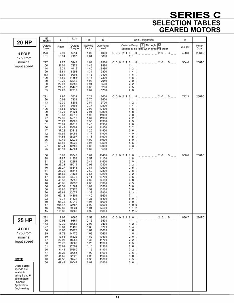
SERIES C
41
N2 R/MIN i lb.in Fm lb lb
OutputSpeed Ratio Output
TorqueServiceFactor
OverhungLoad
Unit Designation
Weight MotorSize
Column Entry 1 Through 20 Spacestobefilledwhenenteringorder
NOTE
Other output speeds are available using 2 and 6 pole motors - Consult Application Engineering
SERIES C
41
SELECTION TABLESGEARED MOTORS
223 7.90 5214 1.00 4000 C 0 7 2 1 8 . 0 _ _ _ _ _ _ 2 0 . B _ _ 458.8 256TC 161 10.94 7197 0.84 3800 1 1 . 227 7.77 5142 1.81 9380 C 0 8 2 1 8 . 0 _ _ _ _ _ _ 2 0 . B _ _ 564.6 256TC 160 11.01 7278 1.48 9380 1 1 . 144 12.24 8115 1.40 9380 1 2 . 129 13.61 8998 1.31 9300 1 4 . 113 15.54 9901 1.15 7400 1 6 . 100 17.60 11553 1.13 7300 1 8 . 89 19.76 13040 1.05 7010 2 0 . 80 22.03 13880 0.94 6500 2 2 . 72 24.47 15447 0.88 6200 2 5 . 65 27.22 17213 0.82 5700 2 8 . 221 7.97 5332 3.24 8600 C 0 9 2 1 8 . 0 _ _ _ _ _ _ 2 0 . B _ _ 712.3 256TC 160 10.98 7331 2.70 9400 1 1 . 143 12.30 8203 2.54 9700 1 2 . 127 13.81 9198 2.37 10800 1 4 . 106 16.68 10622 2.02 10400 1 6 . 99 17.79 11821 2.04 10800 1 8 . 89 19.88 13218 1.90 11900 2 0 . 77 22.96 14612 1.67 11900 2 2 . 68 25.73 16306 1.56 11900 2 5 . 61 28.89 18313 1.45 11900 2 8 . 56 31.43 20704 1.44 11900 3 2 . 47 37.22 23412 1.25 11900 3 6 . 42 41.59 26098 1.17 11900 4 0 . 40 44.55 28997 1.16 11900 4 5 . 36 49.49 32038 1.09 11900 5 0 . 31 57.66 35930 0.95 10500 5 6 . 27 65.74 40788 0.88 10000 6 3 . 25 69.91 44861 0.82 9500 7 1 .
106 16.63 10745 3.61 11400 C 1 0 2 1 1 6 . _ _ _ _ _ _ 2 0 . B _ _ 968.0 256TC 98 17.87 11958 3.57 11100 1 8 . 91 19.29 12891 3.41 11400 2 0 . 76 23.23 15012 2.95 12400 2 2 . 70 25.27 16343 2.81 12600 2 5 . 61 28.70 18545 2.60 12800 2 8 . 55 31.85 21134 2.51 12200 3 2 . 47 37.38 23979 2.14 13700 3 6 . 44 40.36 25856 2.02 14100 4 0 . 40 43.65 28737 2.06 13300 4 5 . 36 48.51 31761 1.89 13300 5 0 . 30 58.85 37275 1.52 13500 5 6 . 26 66.63 42077 1.38 15800 6 3 . 25 69.18 44801 1.40 16600 7 1 . 22 79.71 51424 1.23 15300 8 0 . 19 91.32 57040 1.07 16000 9 0 . 17 101.47 62767 0.99 16600 1 0 0 16 107.80 69034 1.04 17500 1 1 2 15 115.82 73768 0.92 18000 1 2 5
221 7.97 6665 2.59 8600 C 0 9 2 1 8 0 . _ _ _ _ _ _ 2 5 . B _ _ 830.7 284TC 160 10.98 9164 2.16 9400 1 1 . 143 12.30 10253 2.03 9400 1 2 . 127 13.81 11498 1.89 9700 1 4 . 106 16.68 13278 1.61 10800 1 6 . 99 17.79 14776 1.63 10400 1 8 . 89 19.88 16522 1.52 10800 2 0 . 77 22.96 18266 1.33 11700 2 2 . 68 25.73 20383 1.25 11900 2 5 . 61 28.89 22892 1.16 11900 2 8 . 56 31.43 25880 1.15 11900 3 2 . 47 37.22 29265 1.00 11900 3 6 . 42 41.59 32622 0.93 11000 4 0 . 40 44.55 36246 0.93 11000 4 5 . 36 49.49 40047 0.87 10300 5 0 .
4 POLE1750 rpm nominal
input speed
20 HP
4 POLE1750 rpm nominal
input speed
25 HP

SERIES C
42
N2 R/MIN i lb.in Fm lb lb
OutputSpeed Ratio Output
TorqueServiceFactor
OverhungLoad
Unit Designation
Weight MotorSize
Column Entry 1 Through 20 Spacestobefilledwhenenteringorder
NOTE
Other output speeds are available using 2 and 6 pole motors - Consult Application Engineering
42
SELECTION TABLESGEARED MOTORS
158 11.11 9341 3.77 9300 C 1 0 2 1 1 1 . _ _ _ _ _ _ 2 5 . B _ _ 1086.5 284TC 146 12.08 10149 3.59 9900 1 2 . 128 13.72 11502 3.34 10300 1 4 . 106 16.63 13431 2.89 11400 1 6 . 98 17.87 14948 2.85 11000 1 8 . 91 19.29 16113 2.72 11400 2 0 . 76 23.23 18766 2.36 12400 2 2 . 70 25.27 20428 2.24 12600 2 5 . 61 28.70 23181 2.08 12800 2 8 . 55 31.85 26417 2.01 12200 3 2 . 47 37.38 29974 1.72 13700 3 6 . 44 40.36 32320 1.62 14100 4 0 . 40 43.65 35922 1.65 13300 4 5 . 36 48.51 39701 1.52 13500 5 0 . 30 58.85 46593 1.21 15800 5 6 . 26 66.63 52596 1.1 16600 6 3 . 25 69.18 56002 1.12 15300 7 1 . 22 79.71 64280 0.99 16000 8 0 . 19 91.32 71300 0.86 16600 9 0 .
4 POLE1750 rpm nominal
input speed
25 HP
4 POLE1750 rpm nominal
input speed
30 HP 221 7.97 7998 2.16 8600 C 0 9 2 1 8 . 0 _ _ _ _ _ _ 3 0 . B _ _ 824.7 286TC 160 10.98 10997 1.80 9400 1 1 . 143 12.30 12304 1.69 9400 1 2 . 127 13.81 13798 1.58 9700 1 4 . 106 16.68 15934 1.34 10800 1 6 . 99 17.79 17731 1.36 10400 1 8 . 89 19.88 19827 1.27 10800 2 0 . 77 22.96 21919 1.11 11700 2 2 . 68 25.73 24460 1.04 11000 2 5 . 61 28.89 27470 0.97 10600 2 8 . 56 31.43 31056 0.96 10500 3 2 . 47 37.22 35118 0.83 9800 3 6 .
221 7.95 8019 3.79 7700 C 1 0 2 1 8 . 0 _ _ _ _ _ _ 3 0 . B _ _ 1080.5 286TC 158 11.11 11209 3.14 9300 1 1 . 146 12.08 12179 2.99 9900 1 2 . 128 13.72 13803 2.78 10300 1 4 . 106 16.63 16118 2.41 11400 1 6 . 98 17.87 17938 2.38 11000 1 8 . 91 19.29 19336 2.27 11400 2 0 . 76 23.23 22519 1.97 12400 2 2 . 70 25.27 24514 1.87 12600 2 5 . 61 28.70 27818 1.73 12800 2 8 . 55 31.85 31701 1.67 12200 3 2 . 47 37.38 35969 1.43 13700 3 6 . 44 40.36 38784 1.35 14100 4 0 . 40 43.65 43106 1.38 13300 4 5 . 36 48.51 47642 1.26 13500 5 0 . 30 58.85 55912 1.01 15800 5 6 . 26 66.63 63115 0.92 16600 6 3 . 25 69.18 67202 0.94 15300 7 1 . 22 79.71 77136 0.82 14000 8 0 .

SERIES C
43
N2 R/MIN i lb.in Fm lb lb
OutputSpeed Ratio Output
TorqueServiceFactor
OverhungLoad
Unit Designation
Weight MotorSize
Column Entry 1 Through 20 Spacestobefilledwhenenteringorder
NOTE
Other output speeds are available using 2 and 6 pole motors - Consult Application Engineering
43
SELECTION TABLESGEARED MOTORS
40 HP
221 7.97 10664 1.62 11900 C 0 9 2 1 8 . 0 _ _ _ _ _ _ 4 0 . B _ _ 940.1 324TC 160 10.98 14663 1.35 11900 1 1 . 143 12.30 16406 1.27 11900 1 2 . 127 13.81 18397 1.18 11900 1 4 . 106 16.68 21245 1.01 11900 1 6 . 99 17.79 23642 1.02 11900 1 8 . 89 19.88 26436 .95 11900 2 0 . 77 22.96 29225 .83 11900 2 2 .
221 7.97 10693 2.84 7700 C 1 0 2 1 8 . 0 _ _ _ _ _ _ 4 0 . B _ _ 1205 324TC 158 11.11 14946 2.36 9300 1 . 0 146 12.08 16238 2.25 9900 2 . 0 128 13.72 18404 2.09 10300 4 . 0 106 16.63 21490 1.80 11400 6 . 0 98 17.87 23917 1.78 11000 8 . 0 91 19.29 25782 1.70 11400 2 0 . 76 23.23 30025 1.48 12400 2 2 . 70 25.27 32686 1.40 12600 2 5 . 61 28.70 37090 1.30 12800 2 8 . 65 31.85 42268 1.25 12200 3 2 . 55 37.38 47959 1.07 13700 3 6 . 47 40.36 51712 1.01 14400 4 0 . 44 43.65 57475 1.03 13300 4 5 . 36 48.51 63523 0.98 13500 5 0 .
4 POLE1750 rpm nominal
input speed
4 POLE1750 rpm nominal
input speed
50 HP 221 7.97 10664 1.62 8600 C 0 9 2 1 8 . 0 _ _ _ _ _ _ 5 0 . B _ _ 1095 326TC 180 10.98 14663 1.35 9400 143 12.30 16406 1.27 9400 127 13.81 18397 1.18 9700 106 16.68 21245 1.01 10800 99 17.79 23642 1.02 10400 89 19.88 26436 0.95 10800 77 22.96 29225 0.83 11700
221 7.95 10693 2.84 7700 C 1 0 2 1 8 . 0 _ _ _ _ _ _ 5 0 . B _ _ 1360 326TC 158 11.11 14946 2.36 9300 146 12.08 16238 2.25 9900 128 13.72 18404 2.09 10300 106 16.63 21490 1.80 11400 98 17.87 23917 1.78 11000 91 19.29 25782 1.70 11400 76 23.23 30025 1.48 12400 70 25.27 32685 1.40 12600 61 28.7 37090 1.30 12800 55 31.85 42268 1.25 12200 47 37.38 47959 1.07 14100 44 40.36 51712 1.01 13300 40 43.65 57475 1.03 13500 36 48.51 63523 0.95 15800

SERIES C
44
SIZE a1 a2 b b0 b1 c1 e1 f0 h1 h2 o p4 q q1
C0321 2.13 1.38 2.48 3.15 1.57 0.35 2.76 5.47 0.21 3.13 2.44 5.83 2.13 4.29
C0421 2.20 1.38 3.15 4.65 2.56 0.28 3.15 6.22 0.59 3.66 2.56 6.61 2.52 4.69
C0521 2.68 1.77 3.94 5.59 3.03 0.63 3.39 6.97 0.51 4.41 2.76 7.87 2.68 5.28
C0621 3.15 2.20 4.80 6.77 3.78 0.79 4.02 8.58 0.67 5.49 3.54 9.57 3.54 6.65
NEMA Motor Frame Size
C0321 C0421 C0521 C0621
k1 k1 k1 k1
56c 8.98 9.76 10.51 12.17
143Tc / 145Tc 8.98 9.76 10.51 12.17
182Tc / 184Tc 8.66 9.45 10.20 13.15
213Tc / 215Tc - - - 13.15
SIZE s w7 y Hollow Output Bore
D m m1 m2 m3 T U w3
C0321 M8, 0.59 deep 2.76 0.51 0.75 2.05 4.88 4.09 0.80 0.84 0.188 1/4" UNF x 1.50
C0421 M10, 0.79 deep 2.93 0.51 1.25 2.13 5.12 4.80 1.19 1.32 0.25 3/8" UNF x 2.00
C0521 M10, 0.71 deep 3.11 0.51 1.375 2.20 5.51 5.00 1.39 1.53 0.313 1/2" UNF x 2.00
C0621 M12, 0.79 deep 3.98 7.09 1.50 2.76 7.09 6.14 1.78 1.62 0.375 5/8" UNF x 2.75
OD
Setscrew w3
Output Shaft Bore
For Motor Dimensions refer tothe Motor Details page
q q1
* k0k1
y* g
6
* g
h1
c1a2
b4 Holes: 'S'
f0 b0
b1
4 Holes: 'S'
Cover
w7
oo
e1
a1
h2
p4
T
U
m1
m2
m m
m3
∗* For Motor Dimensions refer to The Motor Details page 18
DIMENSIONSDOUBLE REDUCTIONS
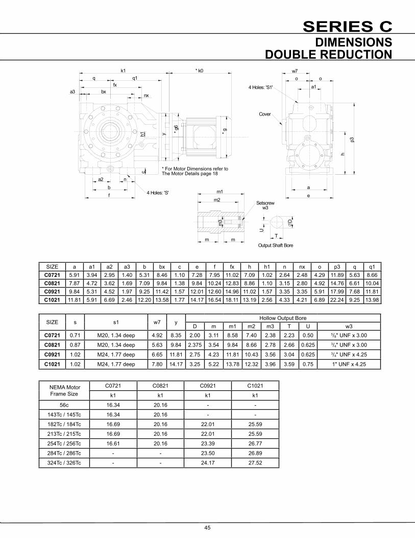
SERIES C
45
SIZE a a1 a2 a3 b bx c e f fx h h1 n nx o p3 q q1C0721 5.91 3.94 2.95 1.40 5.31 8.46 1.10 7.28 7.95 11.02 7.09 1.02 2.64 2.48 4.29 11.89 5.63 8.66C0821 7.87 4.72 3.62 1.69 7.09 9.84 1.38 9.84 10.24 12.83 8.86 1.10 3.15 2.80 4.92 14.76 6.61 10.04C0921 9.84 5.31 4.52 1.97 9.25 11.42 1.57 12.01 12.60 14.96 11.02 1.57 3.35 3.35 5.91 17.99 7.68 11.81C1021 11.81 5.91 6.69 2.46 12.20 13.58 1.77 14.17 16.54 18.11 13.19 2.56 4.33 4.21 6.89 22.24 9.25 13.98
SIZE s s1 w7 y Hollow Output Bore
D m m1 m2 m3 T U w3 C0721 0.71 M20, 1.34 deep 4.92 8.35 2.00 3.11 8.58 7.40 2.38 2.23 0.50 5/8" UNF x 3.00
C0821 0.87 M20, 1.34 deep 5.63 9.84 2.375 3.54 9.84 8.66 2.78 2.66 0.625 3/4" UNF x 3.00
C0921 1.02 M24, 1.77 deep 6.65 11.81 2.75 4.23 11.81 10.43 3.56 3.04 0.625 3/4" UNF x 4.25
C1021 1.02 M24, 1.77 deep 7.80 14.17 3.25 5.22 13.78 12.32 3.96 3.59 0.75 1" UNF x 4.25
NEMA Motor Frame Size
C0721 C0821 C0921 C1021
k1 k1 k1 k1
56c 16.34 20.16 - -
143Tc / 145Tc 16.34 20.16 - -
182Tc / 184Tc 16.69 20.16 22.01 25.59
213Tc / 215Tc 16.69 20.16 22.01 25.59
254Tc / 256Tc 16.61 20.16 23.39 26.77
284Tc / 286Tc - - 23.50 26.89
324Tc / 326Tc - - 24.17 27.52
OD
Setscrew w3
Output Shaft Bore
For Motor Dimensions refer tothe Motor Details page
4 Holes: 'S'
4 Holes: 'S1'
Cover
T
U
m1
m2
m m
m3
∗a2
bf
n
bxa3fx
q q1* k0
y * g6
* g
nx
c
w7o o
a1
a
e
h
p3
h1
k1
DIMENSIONSDOUBLE REDUCTION
* For Motor Dimensions refer to The Motor Details page 18

SERIES C
46
SIZE a1 a2 b b0 b1 c1 e1 f0 h1 h2 o p4 q q1
C0331 2.13 1.38 2.48 3.15 1.57 0.35 2.76 5.47 1.21 3.13 2.44 5.83 2.13 4.29
C0431 2.20 1.38 3.15 4.65 2.56 0.28 3.15 6.22 0.83 3.66 2.56 6.61 2.52 4.69
C0531 2.68 1.77 3.94 5.59 3.03 0.63 3.39 6.97 0.91 4.41 2.76 7.87 2.68 5.28
C0631 3.15 2.20 4.80 6.77 3.78 0.79 4.02 8.58 1.18 5.49 3.54 9.57 3.54 6.65
SIZE s w7 y Hollow Output Bore
D m m1 m2 m3 T U w3
C0331 M8, 0.59 deep 2.76 5.51 0.75 2.05 4.88 4.09 0.80 0.84 0.188 1/4" UNF x 1.50
C0431 M10, 0.79 deep 2.93 5.51 1.25 2.13 5.12 4.80 1.19 1.37 0.25 3/8" UNF x 2.00
C0531 M10, 0.71 deep 3.11 5.51 1.375 2.20 5.51 5.00 1.39 1.53 0.313 1/2" UNF x 2.00
C0631 M12, 0.79 deep 3.98 7.09 1.50 2.76 7.09 6.14 1.78 1.67 0.375 5/8" UNF x 2.75
NEMA Motor Frame Size
C0331 C0431 C0531 C0631
k1 k1 k1 k1
56c 11.18 11.97 12.72 15.35
143Tc / 145Tc 11.18 11.97 12.72 15.35
182Tc / 184Tc 10.87 11.65 12.40 15.04
OD
Setscrew w3
Output Shaft Bore
For Motor Dimensions refer tothe Motor Details page
q q1
* k0k1
y
* g6
* g
h1
c1a2
b4 Holes: 'S'
f0 b0
b1
4 Holes: 'S'
Cover
w7
oo
e1
a1
h2
p4
T
U
m1
m2
m mm
3
∗
DIMENSIONSTRIPLE REDUCTIONS
* For Motor Dimensions refer to The Motor Details page 18

SERIES C
47
SIZE a a1 a2 a3 b bx c e f fx h h1 n nx o p3 q q1
C0731 5.91 3.94 2.95 1.40 5.31 8.46 1.10 7.28 7.95 11.02 7.09 1.34 2.64 2.48 4.29 11.89 5.63 8.66
SIZE s s1 w7 y Hollow Output Bore
D m m1 m2 m3 T U w3
C0731 0.71 M20, 1.34 deep 4.92 8.35 2.0 3.11 8.58 7.40 2.38 2.23 0.50 5/8" UNF x 3.00
NEMA Motor Frame Size
C0731
k1
56c 19.65
143Tc / 145Tc 19.65
182Tc / 184Tc 20.63
213Tc / 215Tc 20.63
OD
Setscrew w3
Output Shaft Bore
For Motor Dimensions refer tothe Motor Details page
4 Holes: 'S'
4 Holes: 'S1'
Cover
T
U
m1
m2
m m
m3
∗a2
bf
n
bxa3fx
q q1
y
nx
c
w7
o o
a1
ae
h
p3
h1
* g6
* g
k0k1
DIMENSIONSTRIPLE REDUCTION
* For Motor Dimensions refer to The Motor Details page 18

SERIES C
48
SIZE a1 a2 b b0 b1 c1 e1 f0 h1 h2 o p4 q q1
C0341 2.13 1.38 2.48 3.15 1.57 0.35 2.76 5.47 0.21 3.13 2.44 5.83 2.13 4.29
C0441 2.20 1.38 3.15 4.65 2.56 0.28 3.15 6.22 0.59 3.66 2.56 6.61 2.52 4.69
C0541 2.68 1.77 3.94 5.59 3.03 0.63 3.39 6.97 0.51 4.41 2.76 7.87 2.68 5.28
C0641 3.15 2.20 4.80 6.77 3.78 0.79 4.02 8.58 0.67 5.49 3.54 9.57 3.54 6.65
SIZE s v2 w7 y Hollow Output Bore
D m m1 m2 m3 T U w3
C0341 M8, 0.59 deep 2.99 2.76 5.51 0.75 2.05 4.88 4.09 0.80 0.84 0.188 1/4" UNF x 1.50
C0441 M10, 0.79 deep 2.99 2.93 5.51 1.25 2.13 5.12 4.80 1.19 1.37 0.25 3/8" UNF x 2.00
C0541 M10, 0.71 deep 2.99 3.11 5.51 1.375 2.20 5.51 5.00 1.39 1.53 0.313 1/2" UNF x 2.00
C0641 M12, 0.79 deep 3.58 3.98 7.09 1.50 2.76 7.09 6.14 1.78 1.67 0.375 5/8" UNF x 2.75
NEMA Motor Frame Size
C0341 C0441 C0541 C0641
k1 k1 k1 k1
56c 16.30 17.09 17.83 20.71
143Tc / 145Tc 16.30 17.09 17.83 20.71
182Tc / 184Tc 15.98 16.77 17.52 20.39
Setscrew w3
Output Shaft Bore
For Motor Dimensions refer tothe Motor Details page
4 Holes: 'S'4 Holes: 'S'
Cover
∗
OD
Setscrew w3
Output Shaft Bore
T
U
m1
m2
m mm
3
q q1
k1 * k0
y
* g6
* g
b
a2
c1
b1b0f0 h1
w7
o 0
e1
a1
h2
p4
v2
DIMENSIONSQUADRUPLE REDUCTIONS
* For Motor Dimensions refer to The Motor Details page 18

SERIES C
49
SIZE a a1 a2 a3 b bx c e f fx h h1 n x o p3 q q1
C0741 5.91 3.94 2.95 1.40 5.31 8.46 1.10 7.28 7.95 11.02 4.09 1.02 2.64 2.48 4.29 11.89 5.63 8.66
C0841 7.87 4.72 3.62 1.69 7.09 9.84 1.38 9.84 10.24 12.83 8.86 1.10 3.15 2.80 4.92 14.76 6.61 10.04
C0941 9.84 5.31 4.53 1.97 9.25 11.42 1.57 12.01 12.60 14.96 11.02 1.57 3.35 3.35 5.91 17.99 7.68 11.81
C1041 11.81 5.91 6.69 2.46 12.20 13.58 1.77 14.17 16.54 18.11 13.19 2.56 4.33 4.21 6.89 22.24 9.25 13.98
SIZE s s1 v2 v3 w7 y Hollow Output Bore
D m m1 m2 m3 T U w3
C0741 0.71 M20, 1.34 deep 3.58 - 4.92 8.35 2.00 3.11 8.58 7.40 2.38 2.23 0.50 5/8" UNF x 3.00
C0841 0.87 M20, 1.34 deep 4.53 - 5.63 9.84 2.375 3.54 9.84 8.66 2.78 2.66 0.625 3/4" UNF x 3.00
C0941 1.02 M24, 1.77 deep 4.53 - 6.65 11.81 2.75 4.23 11.81 10.43 3.56 3.04 0.625 3/4" UNF x 4.25
C1041 1.02 M24, 1.77 deep 5.51 6.10 7.80 14.17 3.25 5.22 13.78 12.32 3.96 3.59 0.75 1" UNF x 4.25
NEMA Motor Frame Size
C0741 C0841 C0941 C1041
k1 k1 k1 k1
56c 24.84 28.27 31.54 48.77
143Tc / 145Tc 24.84 28.27 31.54 48.77
182Tc / 184Tc 24.53 29.25 32.52 52.63
213Tc / 215Tc - 29.25 32.52 52.63
OD
Setscrew w3
Output Shaft Bore
For Motor Dimensions refer tothe Motor Details page
4 Holes: 'S'
4 Holes: 'S1'
Cover
T
U
m1
m2
m m
m3
∗
q q1k1 * k0
fx
bxa3nx
v3v2
y
* g6
* gh1
f
b
a2n
c1
w7
o o
a1
e
a
h
p3
DIMENSIONSQUADRUPLE REDUCTION
* For Motor Dimensions refer to The Motor Details page 18

SERIES C
50
K1
6gø
CW
K1
6gø
CW
Motor Frame Size Lift off Speed (rev/min)
Rated Locking Torque (‘T max’) at motor (lb-in) �g6 K1
100 670 1500 9.84 2.76
112 670 1500 9.84 2.76
132 620 8300 11.81 3.74
160 620 8300 13.77 5.12
180 620 8300 13.77 5.12
200 550 11100 15.74 5.12
Motor Frame Size Lift off Speed (rev/min)
Rated Locking Torque (‘T max’) at motor (lb-in) �g6 K1
182TC / 184TC 670 2650 9.0 3.75
213TC / 215TC 670 2650 9.0 3.75
254TC / 256TC 620 8300 9.0 4.75
284TC / 286TC 620 8300 11.0 5.37
324TC / 326TC 550 11100 13.0 6.00
When a backstop module is fitted dimension K1 should be added to the overall length of the geared motor assembly.
Rotation of outputshaft must be specified when ordering as viewed from the outputshaft end (as shown in the diagram)
Motorized backstop modules can be fitted between the gear unit and motor. The backstop device incorporates high quality centrifugal lift off sprags which are wear free above the lift off speed (rev/min). To ensure correct operation motor speed must exceed lift off speed.
Suitable for ambient temperature -40ºF to + 122ºF
Warning
Removal of motor or backstop will release the drive. Ensure all driven machinery is secure prior to any maintenance work
IEC B5 FLANGE
NEMA C FLANGE
CW - Free Rotation - Clockwise Locked - Anticlockwise
AC - Free Rotation - Anticlockwise Locked - Clockwise
MOTORIZED BACKSTOP MODULE

SERIES C
51
NOTES

SERIES C
52
REDUCER
SERIES C
REDUCER

SERIES C
53
Output
Frb
B
Input
Fra
A
Maximum permissible overhung loadsWhen a sprocket, gear etc. is mounted on the shaft a calculation, as below, must be made to determine the overhung load on the shaft, and the results compared to the maximum permissible overhung loads tabulated. Overhung loads can be reduced by increasing the diameter of the sprocket, gear, etc. If the maximum permissible overhung load is exceeded, the sprocket, gear, etc. should be mounted on a separate shaft, flexibly coupled and supported in its own bearings, or the gear unit shaft should be extended to run in an outboard bearing. Alternatively, a larger gear is often a less expensive solution.
Permissible overhung loads vary according to the direction of rotation. The values tabulated are for the most unfavourable direction with the unit transmitting full rated power and the load P applied midway along the shaft extension. Hence they can sometimes be increased for a more favourable direction of rotation, or if the power transmitted is less than the rated capacity of the gear unit, or if the load is applied nearer to the gear unit case. Refer to our Application Engineers for further details. In any event, the sprocket, gear etc. should be positioned as close as possible to the gear unit case in order to reduce bearing loads and shaft stresses, and to prolong life. All units will accept 100% momentary overload on stated capacities.
Overhung load (lbs)P =
whereP = equivalent overhung load (lbs)HP = power transmitted by the shaft (HP)N = speed of shaft (rpm)R = pitch radius of sprocket, etc. (in)K = factor
Size of unit No. of Reductions Dimension A (mm) Dimension B (mm) C03 2 - 3 0.69 0.79C04 2 - 3 0.91 0.79C05 2 - 3 1.18 0.79C06 2 - 5 1.24 0.79C07 2 1.50 0.98C07 3 - 5 1.50 0.79C08 2 2.36 1.18C08 4 - 5 2.36 0.79C09 2 2.66 1.57C09 4 - 5 2.66 0.79C10 2 3.35 2.17C10 4 3.35 0.98C10 5 3.35 0.79
Overhung load K (factor)
Chain sprocket* 1.00Spur or helical pinion 1.25Vee belt sheave 1.50Flat belt pulley 2.00
* If multistrand chain drives are equally loaded and the outer strand is further than dimension A output or B input, refer to our Application Engineers.
HP x 63,000 x K N x R
Distance midway along the shaft extension
Inputshaft Overhung Loads, Frb (lbs) 1750 rpm - Two Three and Four Stage Units
For output overhung load Fra consult ratings tables pages 21 to 42 and pages 54 to 74.
Axial Thrust Capacities (lbs) No check or calculation is required for axial loads (FA) towards or away from the unit up to 50% of the permissible overhung load. If the axial thrust considerably exceeds these values or if there is a combination of axial thrust loads and overhung loads please contact our Application Engineers.
C03 C04 C05 C06 C07 C08 C09 C10 2 Stage 300 300 280 280 400 620 700 800
4 Stage 300 300 300 300 300 300 300 490
OVERHUNG & AXIAL LOADS(NEWTONS) ON SHAFTS

SERIES C
54
N2 - Output Speed (rpm) M2 - Output Torque (lb-in) Pm - Input Power (HP) i - Exact Ratio (:1) η - Efficiency (%) fra - OverhungLoad(lb’s)
InputSpeed
N1 (rpm)
N2 (rpm)
i(:1)
M2 (lb-in)
η (%)
Pm (HP
fra (lb’s)
N2 (rpm)
i(:1)
M2 (lb-in)
η (%)
Pm (HP)
fra (lb’s)
ColumnEntry
6 7 8
8 . 0 1750 204 8.591 685 84% 2.64 625 204 8.591 1160 85% 4.41 1180 1160 135 750 1.75 135 1270 2.92 860 100 809 1.53 100 1360 2.54 1 1 . 1750 151 11.61 744 83% 2.14 625 151 11.61 1260 84% 3.59 1180 1160 99.9 818 1.42 99.9 1380 2.38 860 74.1 874 1.24 74.1 1470 2.06 1 2 . 1750 133 13.20 767 83% 1.94 625 133 13.20 1300 84% 3.26 1180 1160 87.9 843 1.29 87.9 1420 2.16 860 65.2 903 1.12 65.2 1510 1.86 1 4 . 1750 117 14.95 794 82% 1.80 625 117 14.95 1350 84% 2.98 1180 1160 77.6 872 1.19 77.6 1470 1.98 860 57.5 929 1.03 57.5 1570 1.71 1 6 . 1750 107 16.36 736 73% 1.71 625 107 16.36 1210 76% 2.70 1180 1160 70.9 813 1.13 70.9 1340 1.79 860 52.6 874 1.00 52.6 1430 1.57 1 8 . 1750 91.5 19.13 845 82% 1.50 625 91.5 19.13 1430 83% 2.50 1180 1160 60.64 920 0.99 60.64 1560 1.66 860 44.96 982 0.85 44.96 1660 1.43 2 0 . 1750 84.9 20.61 861 81% 1.43 625 84.9 20.61 1460 83% 2.37 1180 1160 56.3 938 0.95 56.3 1590 1.57 860 41.7 1000 0.82 41.7 1640 1.31 2 2 . 1750 79.1 22.11 801 72% 1.40 625 79.1 22.11 1320 74% 2.24 1180 1160 52.5 882 0.93 52.5 1450 1.48 860 38.9 947 0.81 38.9 1540 1.28 2 5 . 1750 69.6 25.14 828 71% 1.29 625 69.6 25.14 1360 74% 2.03 1180 1160 46.1 912 0.85 46.1 1490 1.35 860 34.2 974 0.74 34.2 1580 1.16 2 8 . 1750 61.4 28.48 857 71% 1.18 625 61.4 28.48 1410 73% 1.88 1180 1160 40.7 938 0.78 40.7 1540 1.25 860 30.2 1000 0.67 30.2 1640 1.08 3 2 . 1750 51.9 33.71 965 80% 0.99 625 51.9 33.71 1640 81% 1.67 1180 1160 34.4 1050 0.66 34.4 1780 1.11 860 25.5 1150 0.58 25.5 1850 0.92 3 6 . 1750 48.0 36.43 913 70% 0.99 625 48.0 36.43 1500 72% 1.59 1180 1160 31.8 1000 0.66 31.8 1630 1.05 860 23.6 1060 0.57 23.6 1730 0.90 4 0 . 1750 44.6 39.26 931 70% 0.94 625 44.6 39.26 1530 72% 1.50 1180 1160 29.5 1020 0.62 29.5 1660 1.00 860 21.9 1090 0.54 21.9 1770 0.85 4 5 . 1750 38.5 45.50 1040 79% 0.80 625 38.5 45.50 1760 80% 1.34 1180 1160 25.5 1150 0.53 25.5 1850 0.89 860 18.9 1270 0.48 18.9 1820 0.68
C0321 C0421
DOUBLE REDUCTION RATINGSSIZES C03 - C04

SERIES C
55
N2 - Output Speed (rpm) M2 - Output Torque (lb-in) Pm - Input Power (HP) i - Exact Ratio (:1) η - Efficiency (%) fra - OverhungLoad(lb’s)
InputSpeed
N1 (rpm)
N2 (rpm)
i(:1)
M2 (lb-in)
η (%)
Pm (HP
fra (lb’s)
N2 (rpm)
i(:1)
M2 (lb-in)
η (%)
Pm (HP)
fra (lb’s)
ColumnEntry
6 7 8
5 0 . 1750 32.8 53.31 1070 78% 0.66 625 32.8 53.31 1820 80% 1.3 1180 1160 21.8 1210 0.44 21.8 1830 0.756 860 16.1 1340 0.44 16.1 1810 0.378 5 6 . 1750 31.1 56.19 1020 69% 0.73 625 31.1 56.19 1670 70% 1.28 1180 1160 20.6 1110 0.48 20.6 1810 0.766 860 15.3 1190 0.42 15.3 1930 0.464 6 3 . 1750 27.3 64.21 1050 68% 0.67 625 27.3 64.21 1720 70% 1.16 1180 1160 18.1 1150 0.44 18.1 1880 0.699 860 13.4 1230 0.38 13.4 2000 0.428 7 1 . 1750 23.5 74.55 1220 77% 0.59 625 23.5 74.55 1840 78% 1.08 1180 1160 15.6 1350 0.39 15.6 1810 0.542 860 11.5 1360 0.32 11.5 1800 0.271 8 0 . 1750 21.1 82.83 1250 77% 0.54 625 21.1 82.83 1710 78% 0.911 1180 1160 14.0 1350 0.36 14.0 1670 0.456 860 10.4 1360 0.29 10.4 1660 0.228 9 0 . 1750 20.2 86.67 1180 66% 0.57 625 20.2 86.67 1930 68% 0.994 1180 1160 13.4 1280 0.38 13.4 2110 0.592 860 9.92 1360 0.32 9.92 2240 0.358 1 0 0 1750 17.2 101.5 1220 64% 0.52 625 17.2 101.5 1990 68% 0.879 1180 1160 11.4 1330 0.35 11.4 2170 0.528 860 8.47 1360 0.29 8.47 2320 0.325 1 1 2 1750 15.3 114.3 1360 75% 0.44 625 15.3 114.3 1500 76% 0.456 1180 1160 10.1 1120 0.29 10.1 1140 0.228 860 7.524 1120 0.18 7.524 1130 0.114 1 2 5 1750 13.5 129.9 1290 74% 0.37 625 13.5 129.9 1290 75% 0.395 1180 1160 8.93 1120 0.25 8.93 1120 0.197 860 6.62 1120 0.16 6.62 1120 0.099 1 4 0 1750 12.3 142.0 1310 63% 0.41 625 12.3 142.0 2140 65% 0.69 1180 1160 8.17 1360 0.27 8.17 2820 0.416 860 6.06 1360 0.21 6.06 2600 0.238 1 6 0 1750 11.1 157.8 1340 61% 0.39 625 11.1 157.8 2190 64% 0.639 1180 1160 7.35 1360 0.26 7.35 2640 0.385 860 5.45 1360 0.19 5.45 2620 0.216 2 1 2 1750 8.03 217.8 1360 62% 0.28 625 8.03 217.8 2370 63% 0.456 1180 1160 5.33 1360 0.19 5.33 1800 0.228 860 3.95 1360 0.14 3.95 1770 0.114 2 5 0 1750 7.07 247.5 1360 62% 0.25 625 7.07 247.5 2050 63% 0.395 1180 1160 4.69 1360 0.16 4.69 1750 0.197 860 3.47 1360 0.12 3.47 1730 0.099
C0321 C0421
DOUBLE REDUCTION RATINGSSIZES C03 - C04

SERIES C
56
N2 - Output Speed (rpm) M2 - Output Torque (lb-in) Pm - Input Power (HP) i - Exact Ratio (:1) η - Efficiency (%) fra - OverhungLoad(lb’s)
InputSpeed
N1 (rpm)
N2 (rpm)
i(:1)
M2 (lb-in)
η (%)
Pm (HP
fra (lb’s)
N2 (rpm)
i(:1)
M2 (lb-in)
η (%)
Pm (HP)
fra (lb’s)
ColumnEntry
6 7 8
8 . 0 1750 211 8.312 1710 87% 6.57 1650 213 8.232 3040 89% 11.52 2580 1160 140 2020 4.35 141 3600 7.64 860 103 2260 4.26 104 4040 7.52 1 1 . 1750 150 11.66 1960 86% 5.43 1650 151 11.57 3510 89% 9.46 2580 1160 99.5 2290 3.60 100.3 4120 6.27 860 73.8 2550 3.47 74.3 4580 6.07 1 2 . 1750 136 12.85 2040 86% 5.13 1650 135 12.97 3670 89% 8.83 2580 1160 90.3 2370 3.40 89.4 4290 5.85 860 66.9 2640 3.26 66.3 4770 5.64 1 4 . 1750 120 14.59 2140 86% 4.74 1650 120 14.56 3840 89% 8.23 2580 1160 79.5 2490 3.14 79.7 4470 5.45 860 58.9 2750 2.99 59.1 4920 5.18 1 6 . 1750 109 16.09 2710 78% 6.00 1650 110 15.93 4260 79% 9.40 2580 1160 72.1 2970 3.97 72.8 4960 6.23 860 53.4 3410 3.71 54.0 5280 5.73 1 8 . 1750 94.4 18.53 2340 85% 4.13 1650 94.6 18.49 4200 88% 7.17 2580 1160 62.60 2700 2.73 62.74 4870 4.75 860 46.41 2980 2.58 46.51 5390 4.52 2 0 . 1750 83.1 21.05 2450 85% 3.80 1650 83.5 20.96 4400 88% 6.62 2580 1160 55.1 2810 2.52 55.3 5080 4.39 860 40.9 3110 2.37 41.0 5610 4.15 2 2 . 1750 77.6 22.56 2960 77% 4.73 1650 78.1 22.40 4850 80% 7.51 2580 1160 51.4 3200 3.14 51.8 5360 4.98 860 38.1 3360 2.64 38.4 5610 4.27 2 5 . 1750 70.4 24.86 3030 77% 4.40 1650 69.7 25.11 5060 80% 6.99 2580 1160 46.7 3250 2.91 46.2 5480 4.64 860 34.6 3430 2.45 34.2 5750 3.91 2 8 . 1750 62.0 28.24 3110 76% 4.02 1650 62.1 28.18 5200 80% 6.40 2580 1160 41.1 3320 2.67 41.2 5580 4.25 860 30.5 3520 2.24 30.5 5890 3.57 3 2 . 1750 53.8 32.55 2810 83% 2.89 1650 52.3 33.48 5180 87% 4.94 2580 1160 35.6 3240 1.91 34.6 5920 3.27 860 26.4 3530 1.78 25.7 6480 3.04 3 6 . 1750 48.8 35.86 3280 75% 3.39 1650 48.9 35.79 5490 79% 5.39 2580 1160 32.3 3490 2.24 32.4 5860 3.57 860 24.0 3690 1.87 24.0 6200 2.99 4 0 . 1750 43.0 40.74 3350 74% 3.09 1650 43.1 40.57 5610 79% 4.86 2580 1160 28.5 3580 2.05 28.6 6020 3.22 860 21.1 3800 1.72 21.2 6360 2.71 4 5 . 1750 37.4 46.84 3050 82% 2.20 1650 37.0 47.32 5810 86% 3.96 2580 1160 24.8 3600 1.46 24.5 6570 2.63 860 18.4 3580 1.27 18.2 7120 2.39
C0521 C0621
DOUBLE REDUCTION RATINGSSIZES C05 - C06

SERIES C
57
N2 - Output Speed (rpm) M2 - Output Torque (lb-in) Pm - Input Power (HP) i - Exact Ratio (:1) η - Efficiency (%) fra - OverhungLoad(lb’s)
InputSpeed
N1 (rpm)
N2 (rpm)
i(:1)
M2 (lb-in)
η (%)
Pm (HP
fra (lb’s)
N2 (rpm)
i(:1)
M2 (lb-in)
η (%)
Pm (HP)
fra (lb’s)
ColumnEntry
6 7 8
5 0 . 1750 34.4 50.93 3100 81% 1.94 1650 34.6 50.52 5930 86% 3.66 2580 1160 22.8 3610 1.29 23.0 6690 2.43 860 16.9 3580 1.18 17.0 7250 2.28 5 6 . 1750 31.6 55.45 3570 73% 2.45 1650 31.4 55.71 5960 77% 3.86 2580 1160 20.9 3830 1.62 20.8 6440 2.56 860 15.5 3530 1.19 15.4 6820 2.17 6 3 . 1750 27.8 63.00 3670 72% 2.25 1650 27.0 64.80 6160 76% 3.47 2580 1160 18.4 3940 1.49 17.9 6660 2.30 860 13.7 4170 1.25 13.3 7050 1.95 7 1 . 1750 23.9 73.37 3190 80% 1.51 1650 23.7 73.92 6370 85% 2.82 2580 1160 15.8 3570 1.00 15.7 7400 1.87 860 11.7 3570 0.83 11.6 7760 1.69 8 0 . 1750 21.2 82.67 3220 80% 1.35 1650 21.6 80.94 6430 85% 2.60 2580 1160 14.0 3370 0.90 14.3 7560 1.72 860 10.4 3440 0.71 10.6 7740 1.54 9 0 . 1750 19.3 90.67 4110 70% 1.80 1650 19.1 91.58 6880 75% 2.78 2580 1160 12.8 4420 1.19 12.7 7430 1.84 860 9.48 4670 1.00 9.39 7820 1.55 1 0 0 1750 17.8 98.6 4180 70% 1.68 1650 17.9 97.8 6970 74% 2.67 2580 1160 11.8 4480 1.12 11.9 7530 1.77 860 8.72 4740 0.94 8.80 7970 1.50 1 1 2 1750 16.0 109.1 3050 79% 0.98 1650 15.8 110.6 6660 83% 2.01 2580 1160 10.6 2600 0.65 10.5 6320 1.34 860 7.883 2660 0.42 7.776 6440 0.96 1 2 5 1750 14.1 124.0 2630 78% 0.76 1650 14.1 124.0 4270 83% 1.15 2580 1160 9.35 2300 0.50 9.35 4660 0.76 860 6.94 2350 0.33 6.94 4610 0.61 1 4 0 1750 12.3 142.0 4470 68% 1.29 1650 12.2 143.1 7490 72% 2.02 2580 1160 8.17 4810 0.85 8.11 8090 1.34 860 6.06 5120 0.72 6.01 8570 1.13 1 6 0 1750 10.9 160.0 4570 67% 1.18 1650 11.2 156.7 7520 72% 1.85 2580 1160 7.25 4970 0.78 7.40 8230 1.23 860 5.38 5120 0.65 5.49 8570 1.04 2 1 2 1750 8.29 211.1 4820 66% 0.96 1650 8.18 214.0 7520 70% 1.39 2580 1160 5.50 4200 0.64 5.42 8570 0.92 860 4.07 4260 0.42 4.02 8570 0.78 2 5 0 1750 7.29 240.0 4270 66% 0.75 1650 7.29 240.0 7520 70% 1.24 2580 1160 4.83 3710 0.50 4.83 7490 0.82 860 3.58 3760 0.32 3.58 7490 0.61
C0521 C0621
DOUBLE REDUCTION RATINGSSIZES C05 - C06

SERIES C
58
N2 - Output Speed (rpm) M2 - Output Torque (lb-in) Pm - Input Power (HP) i - Exact Ratio (:1) η - Efficiency (%) fra - OverhungLoad(lb’s)
InputSpeed
N1 (rpm)
N2 (rpm)
i(:1)
M2 (lb-in)
η (%)
Pm (HP
fra (lb’s)
N2 (rpm)
i(:1)
M2 (lb-in)
η (%)
Pm (HP)
fra (lb’s)
ColumnEntry
6 7 8
8 . 0 1750 221 7.901 5240 92% 20.02 6050 225 7.77 9300 93% 35.74 6450 1160 147 5460 13.27 149 8640 23.69 6800 860 109 5430 10.19 111 8600 16.24 7100 1 1 . 1750 160 10.94 6020 92% 16.61 6050 159 11.01 10800 92% 29.61 6800 1160 106.0 7080 11.01 105.4 12200 19.62 7000 860 78.6 7500 10.17 78.1 12200 16.44 7750 1 2 . 1750 142 12.29 6310 92% 15.50 6050 143 12.24 11300 93% 27.56 6900 1160 94.4 7400 10.27 94.8 13300 18.27 7200 860 70.0 8250 9.96 70.3 13500 16.18 7700 1 4 . 1750 129 13.52 6550 92% 14.62 6050 129 13.61 11800 92% 26.17 7050 1160 85.8 7660 9.69 85.2 13800 17.35 7500 860 63.6 8530 9.36 63.2 14800 16.13 7700 1 6 . 1750 111 15.80 6020 88% 12.02 6050 113 15.54 11400 89% 22.89 5400 1160 73.4 6730 7.97 74.6 13400 15.17 7850 860 54.4 7250 7.12 55.3 14300 14.11 7850 1 8 . 1750 99.1 17.66 7260 91% 12.54 6050 99.4 17.60 13000 92% 22.29 5600 1160 65.69 8430 8.31 65.91 15100 14.78 7600 860 48.70 9380 7.96 48.86 16200 13.65 8000 2 0 . 1750 87.2 20.07 7620 92% 11.46 6050 88.6 19.76 13600 91% 21.00 5700 1160 57.8 8820 7.60 58.7 15800 13.92 7850 860 42.9 9740 7.20 43.5 16900 12.82 8000 2 2 . 1750 79.9 21.89 6580 88% 9.48 6050 79.4 22.03 131200 89% 185.80 5800 1160 53.0 7290 6.29 52.7 15000 123.16 8550 860 39.3 7750 5.49 39.0 15800 11.00 10700 2 5 . 1750 71.2 24.59 6780 87% 8.80 6050 71.5 24.47 13600 89% 17.34 5900 1160 47.2 7490 5.83 47.4 15400 11.49 8750 860 35.0 7970 5.08 35.1 16200 10.15 10700 2 8 . 1750 64.7 27.03 6950 87% 8.21 6050 64.3 27.22 14100 88% 16.34 6100 1160 42.9 7650 5.44 42.6 15700 10.83 9000 860 31.8 8130 4.72 31.6 16500 9.40 10700 3 2 . 1750 56.8 30.81 6880 90% 6.89 6050 55.1 31.78 16200 91% 15.55 6300 1160 37.7 10200 4.57 36.5 18600 10.31 9000 860 27.9 11200 5.51 27.1 19700 9.30 10700 3 6 . 1750 49.6 35.31 7410 87% 6.70 6050 49.7 35.20 15300 88% 13.71 6400 1160 32.9 8070 4.44 33.0 16600 9.09 10700 860 24.4 8530 3.79 24.4 17300 7.62 10700 4 0 . 1750 43.6 40.15 7620 86% 6.13 6050 44.3 39.51 15700 88% 12.54 6600 1160 28.9 8280 4.06 29.4 17000 8.31 10700 860 21.4 8730 3.45 21.8 17600 6.91 10700 4 5 . 1750 39.7 44.13 7280 89% 5.15 6050 40.1 43.64 18000 89% 12.87 7000 1160 26.3 11400 3.41 26.6 20500 8.53 10700 860 19.5 12100 4.20 19.7 21800 7.66 10700
C0821C0721
DOUBLE REDUCTION RATINGSSIZES C07 - C08

SERIES C
59
N2 - Output Speed (rpm) M2 - Output Torque (lb-in) Pm - Input Power (HP) i - Exact Ratio (:1) η - Efficiency (%) fra - OverhungLoad(lb’s)
InputSpeed
N1 (rpm)
N2 (rpm)
i(:1)
M2 (lb-in)
η (%)
Pm (HP
fra (lb’s)
N2 (rpm)
i(:1)
M2 (lb-in)
η (%)
Pm (HP)
fra (lb’s)
ColumnEntry
6 7 8
5 0 . 1750 35.1 49.90 7350 89% 4.45 6050 35.5 49.26 18800 90% 11.39 7200 1160 23.2 6690 2.95 23.5 21300 7.55 9100 860 17.2 7250 2.23 17.5 22500 6.93 10700 5 6 . 1750 32.6 53.62 8090 85% 4.93 6050 32.1 54.60 16700 86% 9.88 7300 1160 21.6 6440 3.27 21.2 18000 6.55 10700 860 16.0 6820 2.04 15.8 18600 5.41 10700 6 3 . 1750 28.4 61.62 8300 85% 4.40 6050 27.5 63.56 17200 86% 8.74 7450 1160 18.8 6660 2.92 18.3 18500 5.79 10700 860 14.0 7050 1.84 13.5 19000 4.74 10700 7 1 . 1750 25.4 69.00 7750 88% 3.54 6050 25.1 69.64 20900 88% 9.47 7650 1160 16.8 7400 2.35 16.7 23400 6.28 10700 860 12.5 7760 1.74 12.3 24600 5.48 10700 8 0 . 1750 23.2 75.56 7820 87% 3.30 6050 22.9 76.50 21500 88% 8.87 8000 1160 15.4 7560 2.19 15.2 24000 5.88 10700 860 11.4 7740 1.61 11.2 24300 4.93 10700 9 0 . 1750 19.8 88.26 8840 84% 3.31 6050 20.0 87.29 18200 85% 6.81 8100 1160 13.1 7430 2.19 13.3 19600 4.51 10700 860 9.74 7820 1.44 9.85 20300 3.73 10700 1 0 0 1750 17.5 99.8 9010 83% 3.02 6050 17.8 98.5 18600 84% 6.24 9380 1160 11.6 7530 2.00 11.8 20000 4.14 860 8.62 7970 1.31 8.73 20700 3.41 1 1 2 1750 16.8 104.3 8110 86% 2.51 6050 17.1 102.4 23300 88% 7.18 9380 1160 11.1 6320 1.66 11.3 25800 4.76 860 8.245 6440 0.98 8.398 26900 4.07 1 2 5 1750 15.1 115.9 8080 86% 2.25 6050 14.8 117.9 21700 87% 5.87 9380 1160 10.01 4660 1.49 9.84 25400 3.89 860 7.42 4610 0.63 7.29 25700 3.42 1 4 0 1750 12.7 138.0 9550 82% 2.34 6050 12.6 139.3 19800 83% 4.76 9380 1160 8.41 8090 1.55 8.33 21300 3.15 860 6.23 8570 1.03 6.17 21900 2.58 1 6 0 1750 11.6 151.1 9720 82% 2.18 6050 11.4 153.0 20100 82% 4.45 9380 1160 7.68 8230 1.44 7.58 21600 2.95 860 5.69 8570 0.94 5.62 22300 2.43 2 1 2 1750 8.39 208.6 10300 80% 1.71 6050 8.54 204.8 21200 81% 3.55 9380 1160 5.56 8570 1.14 5.66 22600 2.35 860 4.12 8570 0.70 4.20 23300 1.92 2 5 0 1750 7.55 231.8 10500 80% 1.57 6050 7.42 235.8 21700 81% 3.15 9380 1160 5.00 7490 1.04 4.92 23100 2.09 860 3.71 7490 0.55 3.65 23200 1.66
C0721 C0821
DOUBLE REDUCTION RATINGSSIZES C07 - C08

SERIES C
60
N2 - Output Speed (rpm) M2 - Output Torque (lb-in) Pm - Input Power (HP) i - Exact Ratio (:1) η - Efficiency (%) fra - OverhungLoad(lb’s)
InputSpeed
N1 (rpm)
N2 (rpm)
i(:1)
M2 (lb-in)
η (%)
Pm (HP
fra (lb’s)
N2 (rpm)
i(:1)
M2 (lb-in)
η (%)
Pm (HP)
fra (lb’s)
ColumnEntry
6 7 8
8 . 0 1750 219 7.973 17300 93% 64.78 8600 220 7.951 30400 93% 114.15 7700 1160 145 20600 42.94 10000 146 34000 75.67 10000 860 108 23300 42.88 10800 108 34000 62.74 10500 1 1 . 1750 159 10.98 19800 93% 53.84 9400 158 11.11 35200 94% 93.59 9800 1160 105.6 23500 35.69 10000 104.4 41200 62.04 10300 860 78.3 26200 35.01 10800 77.4 44800 58.54 10700 1 2 . 1750 142 12.30 20800 93% 50.49 9400 145 12.08 36500 94% 89.25 9900 1160 94.3 24400 33.47 10000 96.0 43011 59.16 10500 860 69.9 27300 32.57 10800 71.2 46200 55.52 11100 1 4 . 1750 127 13.81 21800 93% 47.13 9700 128 13.72 38400 94% 82.68 10300 1160 84.0 25600 31.24 10400 84.5 45100 54.80 10900 860 62.3 28600 30.39 10800 62.7 48500 51.32 12000 1 6 . 1750 105 16.68 21400 89% 40.03 10800 105 16.63 38800 90% 71.98 11400 1160 69.5 25000 26.53 11100 69.8 44800 47.71 12200 860 51.6 27900 25.65 11900 51.7 48900 44.58 12600 1 8 . 1750 98.4 17.79 24100 93% 40.45 10400 97.9 17.87 42700 93% 71.34 11100 1160 65.21 28100 26.81 11100 64.91 49800 47.29 11600 860 48.34 31200 25.73 11900 48.13 53400 43.84 12400 2 0 . 1750 88.0 19.88 25100 92% 38.11 10800 90.7 19.29 43900 93% 67.95 11400 1160 58.4 29200 25.26 11500 60.1 51200 45.04 12000 860 43.3 32500 24.25 11900 44.6 54900 41.76 13000 2 2 . 1750 76.2 22.96 24300 88% 33.39 11700 75.3 23.23 44400 90% 58.97 12400 1160 50.5 28100 22.14 11900 49.9 50600 39.09 13500 860 37.5 31300 21.14 11900 37.0 52800 34.46 14900 2 5 . 1750 68.0 25.73 25400 89% 30.80 11900 69.3 25.27 45800 90% 55.92 12600 1160 45.1 29300 20.41 11900 45.9 51700 37.06 13900 860 33.4 32700 19.49 11900 34.0 53800 32.28 15600 2 8 . 1750 60.6 28.89 26600 89% 28.73 11900 61.0 28.70 48100 90% 51.71 12800 1160 40.2 30600 19.04 40.4 53100 34.27 14300 860 29.8 34000 18.04 30.0 55200 29.16 15800 3 2 . 1750 55.7 31.43 29700 92% 28.52 11900 54.9 31.85 53000 92% 50.22 12200 1160 36.9 34300 18.90 36.4 61500 33.29 13500 860 27.4 36500 17.22 27.0 65200 30.36 15300 3 6 . 1750 47.0 37.22 29200 88% 24.75 11900 46.8 37.38 51400 90% 42.42 13700 1160 31.2 33500 16.41 31.0 56100 28.12 15600 860 23.1 37000 15.41 23.0 58100 23.57 16200 4 0 . 1750 42.1 41.59 30400 87% 23.33 11900 43.4 40.36 52300 90% 39.98 14100 1160 27.9 34800 15.46 28.7 56100 26.50 16000 860 20.7 38300 14.44 21.3 58900 22.13 16600 4 5 . 1750 39.3 44.55 33600 91% 23.01 11900 40.1 43.65 59300 92% 41.00 13300 1160 26.0 36700 15.25 26.6 67700 27.18 14900 860 19.3 38000 12.79 19.7 72000 24.47 16600
C0921 C1021
DOUBLE REDUCTION RATINGSSIZES C09 - C10

SERIES C
61
N2 - Output Speed (rpm) M2 - Output Torque (lb-in) Pm - Input Power (HP) i - Exact Ratio (:1) η - Efficiency (%) fra - OverhungLoad(lb’s)
InputSpeed
N1 (rpm)
N2 (rpm)
i(:1)
M2 (lb-in)
η (%)
Pm (HP
fra (lb’s)
N2 (rpm)
i(:1)
M2 (lb-in)
η (%)
Pm (HP)
fra (lb’s)
ColumnEntry
6 7 8
5 0 . 1750 35.4 49.49 34800 91% 20.99 11900 36.1 48.51 60100 91% 36.99 13500 1160 23.4 37200 13.92 23.9 70200 24.52 15400 860 17.4 38400 11.63 17.7 73600 22.75 17500 5 6 . 1750 30.4 57.66 34200 87% 18.93 11900 29.7 58.85 56600 88% 30.35 15800 1160 20.1 38600 12.55 19.7 60900 20.12 16600 860 14.9 42100 11.45 14.6 62700 16.52 19600 6 3 . 1750 26.6 65.74 35700 86% 17.53 11900 26.3 66.62 57900 88% 27.42 16600 1160 17.6 40200 11.62 17.4 62100 18.18 17200 860 13.1 43700 10.55 12.9 64000 14.90 19600 7 1 . 1750 25.0 69.91 36900 89% 16.47 11900 25.3 69.18 62800 80% 31.51 15300 1160 16.6 38600 10.92 16.8 74900 20.88 17500 860 12.3 39700 8.71 12.4 76400 18.84 19600 8 0 . 1750 22.7 77.18 37300 90% 14.91 11900 22.0 79.71 63500 90% 24.58 16000 1160 15.0 38900 9.88 14.6 76000 16.29 18400 860 11.1 40100 7.88 10.8 77400 14.72 19600 9 0 . 1750 18.8 93.18 39900 84% 14.15 11900 19.2 91.32 61200 87% 21.39 16600 1160 12.4 44300 9.38 12.7 65700 14.18 19600 860 9.23 47600 8.30 9.42 68000 11.68 19600 1 0 0 1750 16.9 103.5 41200 84% 13.16 11900 17.2 101.5 62200 87% 19.56 17000 1160 11.2 45500 8.72 11.4 67000 12.96 19600 860 8.31 48900 7.67 8.47 69000 10.66 19600 1 1 2 1750 16.5 106.2 38600 89% 11.34 11900 16.2 107.8 71700 89% 20.75 17500 1160 10.9 40100 7.52 10.8 77400 13.75 19600 860 8.098 41200 5.95 7.978 77000 10.95 19600 1 2 5 1750 14.7 119.4 39000 88% 10.31 11900 15.1 115.8 68200 89% 18.37 18000 1160 9.72 40500 6.83 10.02 70300 12.18 19600 860 7.20 41500 5.39 7.43 69900 9.25 19600 1 4 0 1750 12.0 146.2 45200 83% 10.34 11900 12.1 144.7 68300 85% 15.42 19600 1160 7.93 49300 6.86 8.02 71500 10.22 860 5.88 49400 5.56 5.94 73700 8.18 1 6 0 1750 10.8 161.4 46400 83% 9.62 11900 10.5 166.7 68100 85% 13.34 19600 1160 7.19 49400 6.38 6.96 73200 8.85 860 5.33 49400 5.03 5.16 75400 7.26 2 1 2 1750 7.88 222.1 50000 81% 7.72 11900 7.76 225.5 71900 84% 10.54 19600 1160 5.22 49400 5.12 5.14 76600 6.99 860 3.87 39600 3.00 3.81 78100 5.63 2 5 0 1750 7.01 249.7 51300 81% 7.04 11900 7.22 242.3 72700 83% 10.04 19600 1160 4.65 49400 4.67 4.79 77400 6.65 860 3.44 49400 3.33 3.55 78100 5.30
C0921C0921
DOUBLE REDUCTION RATINGSSIZES C09 - C10

SERIES C
62
N2 - Output Speed (rpm) M2 - Output Torque (lb-in) Pm - Input Power (HP) i - Exact Ratio (:1) η - Efficiency (%) fra - OverhungLoad(lb’s)
InputSpeed
N1 (rpm)
N2 (rpm)
i(:1)
M2 (lb-in)
η (%)
Pm (HP
fra (lb’s)
N2 (rpm)
i(:1)
M2 (lb-in)
η (%)
Pm (HP)
fra (lb’s)
ColumnEntry
6 7 8
1 0 0 1750 17 105.4 1329 75% 0.47 625 17 105.4 1820 76% 0.63 1180 1160 11 0.31 11 0.42 860 8 0.00 8 0.00 1 1 8 1750 15 120.40 1360 75% 0.42 625 15 120.40 1810 76% 0.55 1180 1160 9.6 0.28 9.6 0.36 860 7.1 0.00 7.1 0.00 1 3 2 1750 13 130.10 1230 63% 0.42 625 13 130.10 1990 65% 0.65 1180 1160 8.9 0.28 8.9 0.43 860 6.6 0.00 6.6 0.00 1 5 0 1750 12 140.2 1260 63% 0.40 625 12 140.2 2040 64% 0.63 1180 1160 8.3 0.26 8.3 0.42 860 6.1 0.00 6.1 0.00 1 6 0 1750 11 162.5 1360 74% 0.31 625 11 162.5 1790 75% 0.41 1180 1160 7.1 0.21 7.1 0.27 860 5.3 0.00 5.3 0.00 1 8 0 1750 9.2 190.4 1360 73% 0.27 625 9.2 190.4 1780 74% 0.35 1180 1160 6.09 0.18 6.09 0.23 860 4.52 0.00 4.52 0.00 2 0 0 1750 8.7 200.7 1360 62% 0.30 625 8.7 200.7 2290 63% 0.50 1180 1160 5.8 0.20 5.8 0.33 860 4.3 0.00 4.3 0.00 2 2 5 1750 7.6 229.3 1360 61% 0.27 625 7.6 229.3 2400 63% 0.46 1180 1160 5.1 0.18 5.1 0.31 860 3.8 0.00 3.8 0.00 2 6 5 1750 6.6 266.3 1360 72% 0.20 625 6.6 266.3 1760 73% 0.25 1180 1160 4.4 0.13 4.4 0.17 860 3.2 0.00 3.2 0.00 2 8 0 1750 5.9 295.8 1360 72% 0.18 625 5.9 295.8 1750 73% 0.23 1180 1160 3.9 0.12 3.9 0.15 860 2.9 0.00 2.9 0.00 3 1 5 1750 5.7 309.5 1360 60% 0.20 625 5.7 309.5 2650 62% 0.38 1180 1160 3.7 0.13 3.7 0.25 860 2.8 0.00 2.8 0.00 3 6 0 1750 4.8 362.6 1360 60% 0.17 625 4.8 362.6 2790 61% 0.35 1180 1160 3.2 0.12 3.2 0.23 860 2.4 0.00 2.4 0.00 4 0 0 1750 4.3 408.3 1360 72% 0.13 625 4.3 408.3 1740 73% 0.16 1180 1160 2.8 0.09 2.8 0.11 860 2.1 0.00 2.1 0.00 4 5 0 1750 3.8 464.1 1360 71% 0.11 625 3.8 464.1 1730 72% 0.14 1180 1160 2.5 0.08 2.5 0.10 860 1.9 0.00 1.9 0.00 5 0 0 1750 3.5 507.1 1360 59% 0.13 625 3.5 507.1 2740 60% 0.25 1180 1160 2.3 0.08 2.3 0.17 860 1.7 0.00 1.7 0.00 5 6 0 1750 3.1 563.5 1360 58% 0.12 625 3.1 563.5 2730 60% 0.22 1180 1160 2.1 0.08 2.1 0.15 860 1.5 0.00 1.5 0.00 8 0 0 1750 2.2 777.8 1360 58% 0.08 625 2.2 777.8 2690 59% 0.16 1180 1160 1.5 0.06 1.5 0.11 860 1.1 0.00 1.1 0.00 9 0 0 1750 2.0 883.9 1360 57% 0.07 625 2.0 883.9 2670 58% 0.14 1180 1160 1.3 0.05 1.3 0.10 860 1.0 0.00 1.0 0.00
C0331 C0431
TRIPLE REDUCTION RATINGSSIZES C03 - C04

SERIES C
63
N2 - Output Speed (rpm) M2 - Output Torque (lb-in) Pm - Input Power (HP) i - Exact Ratio (:1) η - Efficiency (%) fra - OverhungLoad(lb’s)
InputSpeed
N1 (rpm)
N2 (rpm)
i(:1)
M2 (lb-in)
η (%)
Pm (HP
fra (lb’s)
N2 (rpm)
i(:1)
M2 (lb-in)
η (%)
Pm (HP)
fra (lb’s)
ColumnEntry
6 7 8
1 0 0 1750 17 103.9 3570 78% 1.22 1650 17 103.9 7270 83% 2.34 2580 1160 11 0.81 11 1.55 860 8 0.00 8 0.00 1 1 8 1750 15 118.7 3560 78% 1.07 1650 15 118.0 7500 83% 2.13 2580 1160 9.8 0.71 9.8 1.41 860 7.2 0.00 7.3 0.00 1 3 2 1750 13 130.4 4130 68% 1.29 1650 13 130.0 6800 72% 2.02 2580 1160 8.9 0.86 8.9 1.34 860 6.6 0.00 6.6 0.00 1 5 0 1750 12 140.5 4220 67% 1.24 1650 12 147.1 7060 71% 1.88 2580 1160 8.3 0.83 7.9 1.24 860 6.1 0.00 5.8 0.00 1 6 0 1750 11 160.3 3520 77% 0.79 1650 10 169.8 7520 81% 1.52 2580 1160 7.2 0.52 6.8 1.01 860 5.4 0.00 5.1 0.00 1 8 0 1750 9.3 187.8 3500 76% 0.68 1650 9.5 184.6 7520 81% 1.40 2580 1160 6.18 0.45 6.28 0.93 860 4.58 0.00 4.66 0.00 2 0 0 1750 8.7 201.1 4700 66% 0.98 1650 8.7 201.0 7520 70% 1.48 2580 1160 5.8 0.65 5.8 0.98 860 4.3 0.00 4.3 0.00 2 2 5 1750 7.6 229.8 4900 65% 0.91 1650 7.7 228.4 7520 69% 1.32 2580 1160 5.0 0.60 5.1 0.88 860 3.7 0.00 3.8 0.00 2 6 5 1750 6.7 262.6 3460 75% 0.49 1650 6.1 286.0 7520 80% 0.91 2580 1160 4.4 0.32 4.1 0.60 860 3.3 0.00 3.0 0.00 2 8 0 1750 6.0 291.8 3450 75% 0.44 1650 5.8 299.7 7520 80% 0.87 2580 1160 4.0 0.29 3.9 0.58 860 2.9 0.00 2.9 0.00 3 1 5 1750 5.6 310.2 5170 64% 0.72 1650 5.3 328.7 7520 58% 1.10 2580 1160 3.7 0.48 3.5 0.73 860 2.8 0.00 2.6 0.00 3 6 0 1750 4.8 363.4 5260 64% 0.63 1650 4.9 357.3 7520 67% 0.87 2580 1160 3.2 0.42 3.2 0.58 860 2.4 0.00 2.4 0.00 4 0 0 1750 4.3 402.7 3420 74% 0.32 1650 4.4 395.4 7520 79% 0.67 2580 1160 2.9 0.21 2.9 0.44 860 2.1 0.00 2.2 0.00 4 5 0 1750 3.8 457.7 3410 74% 0.28 1650 3.9 449.5 7520 79% 0.59 2580 1160 2.5 0.19 2.6 0.39 860 1.9 0.00 1.9 0.00 5 0 0 1750 3.4 508.2 5260 62% 0.46 1650 3.4 514.8 7520 66% 0.61 2580 1160 2.3 0.31 2.3 0.41 860 1.7 0.00 1.7 0.00 5 6 0 1750 3.1 564.7 5260 62% 0.42 1650 3.0 580.0 7520 65% 0.55 2580 1160 2.1 0.28 2.0 0.37 860 1.5 0.00 1.5 0.00 8 0 0 1750 2.2 779.4 5260 61% 0.31 1650 2.3 765.3 7520 64% 0.43 2580 1160 1.5 0.20 1.5 0.28 860 1.1 0.00 1.1 0.00 9 0 0 1750 2.0 885.8 5260 61% 0.27 1650 2.0 870.0 7520 64% 0.38 2580 1160 1.3 0.18 1.3 0.25 860 1.0 0.00 1.0 0.00
C0631C0531
TRIPLE REDUCTION RATINGSSIZES C05 - C06

SERIES C
64
N2 - Output Speed (rpm) M2 - Output Torque (lb-in) Pm - Input Power (HP) i - Exact Ratio (:1) η - Efficiency (%) fra - OverhungLoad(lb’s)
InputSpeed
N1 (rpm)
N2 (rpm)
i(:1)
M2 (lb-in)
η (%)
Pm (HP
fra (lb’s)
N2 (rpm)
i(:1)
M2 (lb-in)
η (%)
Pm (HP)
fra (lb’s)
ColumnEntry
6 7 8
1 0 0 1750 18 97.3 12100 86% 4.01 6050 1160 12 2.66 860 9 0.00 1 1 8 1750 15 113.2 12100 86% 3.45 6050 1160 10.2 2.29 860 7.6 0.00 1 3 2 1750 14 125.0 9370 81% 2.57 6050 1160 9.3 1.70 860 6.9 0.00 1 5 0 1750 12 141.7 9600 80% 2.35 6050 1160 8.2 1.56 860 6.1 0.00 1 6 0 1750 11 160.0 12100 85% 2.47 6050 1160 7.3 1.64 860 5.4 0.00 1 8 0 1750 10.2 170.8 12100 84% 2.34 6050 1160 6.79 1.55 860 5.04 0.00 2 0 0 1750 9.0 194.7 10200 80% 1.82 6050 1160 6.0 1.21 860 4.4 0.00 2 2 5 1750 7.7 226.4 10400 79% 1.61 6050 1160 5.1 1.07 860 3.8 0.00 2 6 5 1750 7.0 249.9 12100 84% 1.60 6050 1160 4.6 1.06 860 3.4 0.00 2 8 0 1750 6.4 273.7 12100 84% 1.46 6050 1160 4.2 0.97 860 3.1 0.00 3 1 5 1750 5.5 320.0 11000 78% 1.22 6050 1160 3.6 0.81 860 2.7 0.00 3 6 0 1750 5.1 341.6 11100 78% 1.16 6050 1160 3.4 0.77 860 2.5 0.00 4 0 0 1750 4.7 373.8 12100 82% 1.10 6050 1160 3.1 0.73 860 2.3 0.00 4 5 0 1750 4.2 419.2 12100 82% 0.98 6050 1160 2.8 0.65 860 2.1 0.00 5 0 0 1750 3.5 499.9 11200 76% 0.82 6050 1160 2.3 0.54 860 1.7 0.00 5 6 0 1750 3.2 547.4 11200 76% 0.75 6050 1160 2.1 0.50 860 1.6 0.00 8 0 0 1750 2.3 747.7 11200 75% 0.55 6050 1160 1.6 0.37 860 1.2 0.00 9 0 0 1750 2.1 838.5 11200 75% 0.49 6050 1160 1.4 0.33 860 1.0 0.00
C0731
TRIPLE REDUCTION RATINGSSIZES C07

SERIES C
65
N2 - Output Speed (rpm) M2 - Output Torque (lb-in) Pm - Input Power (HP) i - Exact Ratio (:1) η - Efficiency (%) fra - OverhungLoad(lb’s)
InputSpeed
N1 (rpm)
N2 (rpm)
i(:1)
M2 (lb-in)
η (%)
Pm (HP
fra (lb’s)
N2 (rpm)
i(:1)
M2 (lb-in)
η (%)
Pm (HP)
fra (lb’s)
ColumnEntry
6 7 8
1 0 C 1750 1.82 960 1360 70% 0.056 625 1.82 960 1820 70% 0.075 1180 1160 1.21 0.037 1.21 0.050 860 0.90 0.028 0.90 0.037 1 1 C 1750 1.60 1097 1360 70% 0.049 625 1.60 1097 1820 70% 0.066 1180 1160 1.06 0.033 1.06 0.044 860 0.78 0.024 0.78 0.032 1 2 C 1750 1.43 1220 1360 70% 0.044 625 1.43 1220 1820 70% 0.059 1180 1160 0.95 0.029 0.95 0.039 860 0.70 0.022 0.70 0.029 1 4 C 1750 1.30 1345 1360 70% 0.040 625 1.30 1345 1820 70% 0.054 1180 1160 0.86 0.027 0.86 0.036 860 0.64 0.020 0.64 0.026 1 6 C 1750 1.07 1635 1360 69% 0.033 625 1.07 1635 1700 69% 0.042 1180 1160 0.71 0.022 0.71 0.028 860 0.53 0.016 0.53 0.021 1 8 C 1750 1.01 1735 1360 70% 0.031 625 1.01 1735 1820 70% 0.042 1180 1160 0.67 0.021 0.67 0.028 860 0.50 0.015 0.50 0.020 2 0 C 1750 0.91 1916 1360 69% 0.029 625 0.91 1916 1700 69% 0.036 1180 1160 0.61 0.019 0.61 0.024 860 0.45 0.014 0.45 0.018 2 2 C 1750 0.84 2081 1360 70% 0.026 625 0.84 2081 1820 70% 0.035 1180 1160 0.56 0.017 0.56 0.023 860 0.41 0.013 0.41 0.017 2 5 C 1750 0.72 2426 1360 70% 0.022 625 0.72 2426 1820 70% 0.030 1180 1160 0.48 0.015 0.48 0.020 860 0.35 0.011 0.35 0.015 2 8 C 1750 0.65 2679 1360 69% 0.020 625 0.65 2679 1700 69% 0.026 1180 1160 0.43 0.014 0.43 0.017 860 0.32 0.010 0.32 0.013 3 2 C 1750 0.54 3246 1360 70% 0.017 625 0.54 3246 1820 70% 0.022 1180 1160 0.36 0.011 0.36 0.015 860 0.26 0.008 0.26 0.011 3 6 C 1750 0.49 3585 1360 69% 0.015 625 0.49 3585 1700 69% 0.019 1180 1160 0.32 0.010 0.32 0.013 860 0.24 0.008 0.24 0.009 4 0 C 1750 0.43 4109 1360 69% 0.013 625 0.43 4109 1700 69% 0.017 1180 1160 0.28 0.009 0.28 0.011 860 0.21 0.007 0.21 0.008
C0341 C0441
QUADRUPLE REDUCTION RATINGSSIZES C03 - C04

SERIES C
66
N2 - Output Speed (rpm) M2 - Output Torque (lb-in) Pm - Input Power (HP) i - Exact Ratio (:1) η - Efficiency (%) fra - OverhungLoad(lb’s)
InputSpeed
N1 (rpm)
N2 (rpm)
i(:1)
M2 (lb-in)
η (%)
Pm (HP
fra (lb’s)
N2 (rpm)
i(:1)
M2 (lb-in)
η (%)
Pm (HP)
fra (lb’s)
ColumnEntry
6 7 8
4 5 C 1750 0.37 4670 1360 69% 0.012 625 0.37 4670 1700 70% 0.014 1180 1160 0.25 0.008 0.25 0.010 860 0.18 0.006 0.18 0.007 5 0 C 1750 0.35 4978 1360 68% 0.011 625 0.35 4978 2400 69% 0.019 1180 1160 0.23 0.007 0.23 0.013 860 0.17 0.005 0.17 0.010 5 6 C 1750 0.31 5658 1360 68% 0.010 625 0.31 5658 2400 69% 0.017 1180 1160 0.21 0.007 0.21 0.011 860 0.15 0.005 0.15 0.008 6 3 C 1750 0.27 6485 1360 68% 0.009 625 0.27 6485 2400 69% 0.015 1180 1160 0.18 0.006 0.18 0.010 860 0.13 0.004 0.13 0.007 7 1 C 1750 0.24 7370 1360 68% 0.008 625 0.24 7370 2400 69% 0.013 1180 1160 0.16 0.005 0.16 0.009 860 0.12 0.004 0.12 0.006 8 0 C 1750 0.22 7874 1360 53% 0.009 625 0.22 7874 2400 54% 0.016 1180 1160 0.15 0.006 0.15 0.010 860 0.11 0.004 0.11 0.008 9 0 C 1750 0.20 8949 1360 53% 0.008 625 0.20 8949 2400 54% 0.014 1180 1160 0.13 0.005 0.13 0.009 860 0.10 0.004 0.10 0.007 1 0 K 1750 0.18 9482 1360 53% 0.008 625 0.18 9482 1680 53% 0.009 1180 1160 0.12 0.005 0.12 0.006 860 0.09 0.004 0.09 0.005 1 1 K 1750 0.16 10869 1360 53% 0.007 625 0.16 10869 1680 53% 0.008 1180 1160 0.11 0.004 0.11 0.005 860 0.08 0.003 0.08 0.004 1 2 K 1750 0.14 12352 1360 53% 0.006 625 0.14 12352 1680 53% 0.007 1180 1160 0.09 0.004 0.09 0.005 860 0.07 0.003 0.07 0.004 1 4 K 1750 0.12 14038 1360 52% 0.005 625 0.12 14038 1620 53% 0.006 1180 1160 0.08 0.003 0.08 0.004 860 0.06 0.003 0.06 0.003
C0341 C0441
QUADRUPLE REDUCTION RATINGSSIZES C03 - C04

SERIES C
67
N2 - Output Speed (rpm) M2 - Output Torque (lb-in) Pm - Input Power (HP) i - Exact Ratio (:1) η - Efficiency (%) fra - OverhungLoad(lb’s)
InputSpeed
N1 (rpm)
N2 (rpm)
i(:1)
M2 (lb-in)
η (%)
Pm (HP
fra (lb’s)
N2 (rpm)
i(:1)
M2 (lb-in)
η (%)
Pm (HP)
fra (lb’s)
ColumnEntry
6 7 8
1 0 C 1750 1.85 945 3600 73% 0.14 1650 1.71 1022 6770 77% 0.24 2580 1160 1.23 0.10 1.14 0.16 860 0.91 0.07 0.84 0.12 1 1 C 1750 1.62 1080 3600 73% 0.13 1650 1.58 1111 6770 77% 0.22 2580 1160 1.07 0.08 1.04 0.15 860 0.80 0.06 0.77 0.11 1 2 C 1750 1.46 1201 3600 73% 0.11 1650 1.35 1300 6770 77% 0.19 2580 1160 0.97 0.08 0.89 0.12 860 0.72 0.06 0.66 0.09 1 4 C 1750 1.32 1324 3600 73% 0.10 1650 1.17 1495 6770 77% 0.16 2580 1160 0.88 0.07 0.78 0.11 860 0.65 0.05 0.58 0.08 1 6 C 1750 1.07 1642 3570 72% 0.08 1650 1.08 1625 6770 77% 0.15 2580 1160 0.71 0.06 0.71 0.10 860 0.52 0.04 0.53 0.07 1 8 C 1750 1.03 1707 3600 73% 0.08 1650 0.98 1780 6770 76% 0.14 2580 1160 0.68 0.05 0.65 0.09 860 0.50 0.04 0.48 0.07 2 0 C 1750 0.91 1924 3570 72% 0.07 1650 0.90 1951 6770 77% 0.13 2580 1160 0.60 0.05 0.59 0.08 860 0.45 0.04 0.44 0.06 2 2 C 1750 0.85 2048 3600 73% 0.07 1650 0.75 2342 6770 77% 0.10 2580 1160 0.57 0.04 0.50 0.07 860 0.42 0.03 0.37 0.05 2 5 C 1750 0.73 2387 3600 73% 0.06 1650 0.66 2638 6770 77% 0.09 2580 1160 0.49 0.04 0.44 0.06 860 0.36 0.03 0.33 0.05 2 8 C 1750 0.65 2690 3570 72% 0.05 1650 0.61 2889 6770 76% 0.09 2580 1160 0.43 0.03 0.40 0.06 860 0.32 0.03 0.30 0.04 3 2 C 1750 0.55 3195 3600 73% 0.04 1650 0.57 3067 6770 77% 0.08 2580 1160 0.36 0.03 0.38 0.05 860 0.27 0.02 0.28 0.04 3 6 C 1750 0.49 3599 3570 72% 0.04 1650 0.52 3359 6770 76% 0.07 2580 1160 0.32 0.03 0.35 0.05 860 0.24 0.02 0.26 0.04 4 0 C 1750 0.42 4126 3570 72% 0.03 1650 0.46 3812 6770 76% 0.06 2580 1160 0.28 0.02 0.30 0.04 860 0.21 0.02 0.23 0.03
C0641C0541
QUADRUPLE REDUCTION RATINGSSIZES C05 - C06

SERIES C
68
N2 - Output Speed (rpm) M2 - Output Torque (lb-in) Pm - Input Power (HP) i - Exact Ratio (:1) η - Efficiency (%) fra - OverhungLoad(lb’s)
InputSpeed
N1 (rpm)
N2 (rpm)
i(:1)
M2 (lb-in)
η (%)
Pm (HP
fra (lb’s)
N2 (rpm)
i(:1)
M2 (lb-in)
η (%)
Pm (HP)
fra (lb’s)
ColumnEntry
6 7 8
4 5 C 1750 0.37 4689 3570 72% 0.029 1650 0.40 4334 6770 76% 0.057 2580 1160 0.25 0.019 0.27 0.038 860 0.18 0.014 0.20 0.028 5 0 C 1750 0.37 4778 3480 71% 0.028 1650 0.34 5145 6770 76% 0.048 2580 1160 0.24 0.019 0.23 0.032 860 0.18 0.014 0.17 0.024 5 6 C 1750 0.32 5399 3410 71% 0.025 1650 0.30 5920 6770 76% 0.042 258 1160 0.21 0.016 0.20 0.028 860 0.16 0.012 0.15 0.021 6 3 C 1750 0.28 6189 3410 71% 0.022 1650 0.26 6639 6770 76% 0.037 2580 1160 0.19 0.014 0.17 0.025 860 0.14 0.011 0.13 0.018 7 1 C 1750 0.25 7033 3410 71% 0.019 1650 0.24 7378 6770 58% 0.044 2580 1160 0.16 0.013 0.16 0.029 860 0.12 0.009 0.12 0.022 8 0 C 1750 0.22 7985 4260 55% 0.027 1650 0.21 8388 6770 58% 0.039 2580 1160 0.15 0.018 0.14 0.026 860 0.11 0.013 0.10 0.019 9 0 C 1750 0.19 9075 4260 55% 0.024 1650 0.20 8879 6770 57% 0.037 2580 1160 0.13 0.016 0.13 0.025 860 0.09 0.012 0.10 0.018 1 0 K 1750 0.19 9192 4260 54% 0.024 1650 0.17 10078 6770 57% 0.033 2580 1160 0.13 0.016 0.12 0.022 860 0.09 0.012 0.09 0.016 1 1 K 1750 0.17 10536 4260 54% 0.021 1650 0.15 11457 6770 57% 0.029 2580 1160 0.11 0.014 0.10 0.019 860 0.08 0.010 0.08 0.014 1 2 K 1750 0.15 11974 4260 54% 0.018 1650 0.14 12849 6770 56% 0.026 2580 1160 0.10 0.012 0.09 0.017 860 0.07 0.009 0.07 0.013 1 4 K 1750 0.13 13613 4260 54% 0.016 1650 1160 0.09 0.011 860 0.06 0.008
C0541 C0641
QUADRUPLE REDUCTION RATINGSSIZES C05 - C06

SERIES C
69
N2 - Output Speed (rpm) M2 - Output Torque (lb-in) Pm - Input Power (HP) i - Exact Ratio (:1) η - Efficiency (%) fra - OverhungLoad(lb’s)
InputSpeed
N1 (rpm)
N2 (rpm)
i(:1)
M2 (lb-in)
η (%)
Pm (HP
fra (lb’s)
N2 (rpm)
i(:1)
M2 (lb-in)
η (%)
Pm (HP)
fra (lb’s)
ColumnEntry
6 7 8
1 0 C 1750 1.73 1009 11900 81% 0.40 6050 1160 1.15 0.27 860 0.85 0.20 1 1 C 1750 1.59 1097 11900 81% 0.37 6050 1160 1.06 0.25 860 0.78 0.18 1 2 C 1750 1.44 1213 11900 80% 0.34 6050 1160 0.96 0.23 860 0.71 0.17 1 4 C 1750 1.25 1396 11900 80% 0.30 6050 1160 0.83 0.20 860 0.62 0.15 1 6 C 1750 1.15 1517 11900 80% 0.27 6050 1160 0.76 0.18 860 0.57 0.13 1 8 C 1750 1.05 1662 11900 80% 0.25 6050 1160 0.70 0.16 860 0.52 0.12 2 0 C 1750 0.88 1995 11900 80% 0.21 6050 1160 0.58 0.14 860 0.43 0.10 2 2 C 1750 0.80 2186 11900 80% 0.19 6050 1160 0.53 0.13 860 0.39 0.09 2 5 C 1750 0.71 2463 11900 80% 0.17 6050 1160 0.47 0.11 860 0.35 0.08 2 8 C 1750 0.61 2863 11900 80% 0.14 6050 1160 0.41 0.10 860 0.30 0.07 3 2 C 1750 0.56 3135 11900 80% 0.13 6050 1160 0.37 0.09 860 0.27 0.06 3 6 C 1750 0.52 3359 11900 80% 0.12 6050 1160 0.35 0.08 860 0.26 0.06 4 0 C 1750 0.43 4046 11900 80% 0.10 6050 1160 0.29 0.07 860 0.21 0.05
C0741
QUADRUPLE REDUCTION RATINGSSIZES C07

SERIES C
70
N2 - Output Speed (rpm) M2 - Output Torque (lb-in) Pm - Input Power (HP) i - Exact Ratio (:1) η - Efficiency (%) fra - OverhungLoad(lb’s)
InputSpeed
N1 (rpm)
N2 (rpm)
i(:1)
M2 (lb-in)
η (%)
Pm (HP
fra (lb’s)
N2 (rpm)
i(:1)
M2 (lb-in)
η (%)
Pm (HP)
fra (lb’s)
ColumnEntry
6 7 8
4 5 C 1750 0.40 4329 11900 80% 0.095 6050 1160 0.27 0.063 860 0.20 0.047 5 0 C 1750 0.36 4913 11200 78% 0.081 6050 1160 0.24 0.054 860 0.18 0.040 5 6 C 1750 0.31 5585 11200 78% 0.071 6050 1160 0.21 0.047 860 0.15 0.035 6 3 C 1750 0.28 6206 10100 78% 0.058 6050 1160 0.19 0.038 860 0.14 0.028 7 1 C 1750 0.25 7117 10100 72% 0.055 6050 1160 0.16 0.036 860 0.12 0.027 8 0 C 1750 0.22 8091 10100 72% 0.048 6050 1160 0.14 0.032 860 0.11 0.024 9 0 C 1750 0.20 8657 10600 71% 0.048 6050 1160 0.13 0.032 860 0.10 0.024 1 0 K 1750 0.18 9826 10600 71% 0.042 6050 1160 0.12 0.028 860 0.09 0.021 1 1 K 1750 0.16 11171 10600 71% 0.037 6050 1160 0.10 0.025 860 0.08 0.018 1 2 K 1750 0.14 12412 10800 71% 0.034 6050 1160 0.09 0.023 860 0.07 0.017
C0741
QUADRUPLE REDUCTION RATINGSSIZES C07

SERIES C
71
InputSpeed
N1 (rpm)
N2 (rpm)
i(:1)
M2 (lb-in)
η (%)
Pm (HP
fra (lb’s)
N2 (rpm)
i(:1)
M2 (lb-in)
η (%)
Pm (HP)
fra (lb’s)
ColumnEntry
6 7 8
N2 - Output Speed (rpm) M2 - Output Torque (lb-in) Pm - Input Power (HP) i - Exact Ratio (:1) η - Efficiency (%) fra - OverhungLoad(lb’s)
1 6 0 1750 11.18 156 23000 81% 5.039 9380 10.96 160 42500 82% 8.974 11900 1160 7.41 3.340 7.26 5.948 860 5.50 2.476 5.39 4.410 1 8 0 1750 9.91 177 23000 81% 4.464 9380 9.86 177 42500 82% 8.077 11900 1160 6.57 2.959 6.54 5.354 860 4.87 2.194 4.85 3.969 2 1 2 1750 7.96 220 23000 81% 3.584 9380 7.79 225 42500 82% 6.383 11900 1160 5.27 2.376 5.17 4.231 860 3.91 1.762 3.83 3.137 2 5 0 1750 7.05 248 23000 81% 3.176 9380 7.02 249 42500 82% 5.745 11900 1160 4.67 2.105 4.65 3.808 860 3.46 1.561 3.45 2.823 2 8 0 1750 6.32 277 23000 81% 2.849 9380 6.20 282 42500 82% 5.074 11900 1160 4.19 1.889 4.11 3.363 860 3.11 1.400 3.04 2.493 3 2 0 1750 5.60 312 23000 81% 2.524 9380 5.58 314 42500 82% 4.575 11900 1160 3.71 1.673 3.70 3.033 860 2.75 1.240 2.74 2.248 3 6 0 1750 4.98 351 23000 81% 2.243 9380 4.88 359 42500 82% 3.995 11900 1160 3.30 1.487 3.23 2.648 860 2.45 1.102 2.40 1.963 4 0 0 1750 4.39 398 23000 81% 1.979 9380 4.30 407 42500 82% 3.524 11900 1160 2.91 1.312 2.85 2.336 860 2.16 0.973 2.11 1.732 4 5 0 1750 3.89 450 23000 81% 1.753 9380 3.87 452 42500 82% 3.178 11900 1160 2.58 1.162 2.57 2.107 860 1.91 0.862 1.90 1.562 5 0 0 1750 3.68 475 23000 81% 1.659 9380 3.61 485 42500 82% 2.955 11900 1160 2.44 1.100 2.39 1.959 860 1.81 0.815 1.77 1.452 5 6 0 1750 3.20 547 23000 81% 1.441 9380 3.13 558 42500 82% 2.566 11900 1160 2.12 0.955 2.08 1.701 860 1.57 0.708 1.54 1.261 6 3 0 1750 2.75 636 23000 81% 1.239 9380 2.69 649 42500 82% 2.207 11900 1160 1.82 0.821 1.79 1.463 860 1.35 0.609 1.32 1.084 7 1 0 1750 2.46 712 23000 81% 1.107 9380 2.41 727 42500 82% 1.972 11900 1160 1.63 0.734 1.60 1.307 860 1.21 0.544 1.18 0.969 8 0 0 1750 2.31 759 23000 81% 1.039 9380 2.26 774 42500 82% 1.850 11900 1160 1.53 0.689 1.50 1.227 860 1.13 0.511 1.11 0.909 9 0 0 1750 1.95 899 23000 81% 0.877 9380 1.91 918 42500 82% 1.561 11900 1160 1.29 0.581 1.26 1.035 860 0.96 0.431 0.94 0.767 1 0 C 1750 1.82 960 23000 81% 0.821 9380 1.79 980 42500 82% 1.462 11900 1160 1.21 0.544 1.18 0.969 860 0.90 0.404 0.88 0.719 1 1 C 1750 1.61 1084 23000 81% 0.727 9380 1.61 1089 42500 81% 1.337 11900 1160 1.07 0.482 1.07 0.886 860 0.79 0.358 0.79 0.657 1 2 C 1750 1.47 1191 23000 81% 0.662 9380 1.44 1216 42500 82% 1.178 11900 1160 0.97 0.439 0.95 0.781 860 0.72 0.325 0.71 0.579
C0841 C0941
QUADRUPLE REDUCTION RATINGSSIZES C08 - C09

SERIES C
72
InputSpeed
N1 (rpm)
N2 (rpm)
i(:1)
M2 (lb-in)
η (%)
Pm (HP
fra (lb’s)
N2 (rpm)
i(:1)
M2 (lb-in)
η (%)
Pm (HP)
fra (lb’s)
ColumnEntry
6 7 8
N2 - Output Speed (rpm) M2 - Output Torque (lb-in) Pm - Input Power (HP) i - Exact Ratio (:1) η - Efficiency (%) fra - OverhungLoad(lb’s)
1 4 C 1750 1.25 1405 23000 81% 0.561 9380 1.22 1434 42500 82% 0.999 11900 1160 0.83 0.372 0.81 0.662 860 0.61 0.276 0.60 0.491 1 6 C 1750 1.14 1532 23000 80% 0.521 9380 1.14 1538 42500 81% 0.944 11900 1160 0.76 0.345 0.75 0.626 860 0.56 0.256 0.56 0.464 1 8 C 1750 0.92 1901 23000 80% 0.420 9380 0.92 1908 42500 81% 0.761 11900 1160 0.61 0.278 0.61 0.504 860 0.45 0.206 0.45 0.374 2 0 C 1750 0.84 2088 23000 79% 0.387 9380 0.83 2107 42500 81% 0.692 11900 1160 0.56 0.257 0.55 0.459 860 0.41 0.190 0.41 0.340 2 2 C 1750 0.78 2242 23000 80% 0.356 9380 0.78 2250 42500 81% 0.648 11900 1160 0.52 0.236 0.52 0.430 860 0.38 0.175 0.38 0.319 2 5 C 1750 0.71 2463 23000 79% 0.328 9380 0.70 2484 42500 81% 0.585 11900 1160 0.47 0.218 0.47 0.387 860 0.35 0.161 0.35 0.287 2 8 C 1750 0.65 2697 23000 79% 0.300 9380 0.64 2720 42500 81% 0.536 11900 1160 0.43 0.199 0.43 0.355 860 0.32 0.147 0.32 0.264 3 2 C 1750 0.53 3305 23000 79% 0.245 9380 0.52 3334 42500 81% 0.438 11900 1160 0.35 0.162 0.35 0.290 860 0.26 0.120 0.26 0.215 3 6 C 1750 0.47 3761 23000 80% 0.212 9380 0.46 3775 42500 81% 0.385 11900 1160 0.31 0.141 0.31 0.255 860 0.23 0.104 0.23 0.189 4 0 C 1750 0.42 4131 23000 79% 0.196 9380 0.42 4167 42500 81% 0.350 11900 1160 0.28 0.130 0.28 0.232 860 0.21 0.096 0.21 0.172 4 5 C 1750 0.40 4423 23000 78% 0.185 9380 0.38 4586 42500 80% 0.322 11900 1160 0.26 0.123 0.25 0.213 860 0.19 0.091 0.19 0.158 5 0 C 1750 0.36 4929 23000 78% 0.166 9380 0.34 5112 42500 80% 0.288 11900 1160 0.24 0.110 0.23 0.191 860 0.17 0.082 0.17 0.142 5 6 C 1750 0.32 5528 23000 78% 0.148 9380 0.31 5733 42500 80% 0.257 11900 1160 0.21 0.098 0.20 0.170 860 0.16 0.073 0.15 0.126 6 3 C 1750 0.27 6366 23000 78% 0.129 9380 0.27 6447 42500 79% 0.230 11900 1160 0.18 0.085 0.18 0.153 860 0.14 0.063 0.13 0.113 7 1 C 1750 0.26 6707 23000 73% 0.130 9380 0.25 7041 42500 75% 0.224 11900 1160 0.17 0.086 0.16 0.148 860 0.13 0.064 0.12 0.110 8 0 C 1750 0.21 8262 23000 73% 0.106 9380 0.22 7897 42500 75% 0.200 11900 1160 0.14 0.070 0.15 0.132 860 0.10 0.052 0.11 0.098 9 0 C 1750 0.20 8845 23000 72% 0.100 9380 0.20 8718 42500 75% 0.181 11900 1160 0.13 0.066 0.13 0.120 860 0.10 0.049 0.10 0.089 1 0 K 1750 0.18 9859 23000 72% 0.090 9380 0.18 9594 42500 73% 0.168 11900 1160 0.12 0.060 0.12 0.111 860 0.09 0.044 0.09 0.083
C0841 C0941
QUADRUPLE REDUCTION RATINGSSIZES C08 - C09

SERIES C
73
InputSpeed
N1 (rpm)
N2 (rpm)
i(:1)
M2 (lb-in)
η (%)
Pm (HP
fra (lb’s)
N2 (rpm)
i(:1)
M2 (lb-in)
η (%)
Pm (HP)
fra (lb’s)
ColumnEntry
6 7 8
N2 - Output Speed (rpm) M2 - Output Torque (lb-in) Pm - Input Power (HP) i - Exact Ratio (:1) η - Efficiency (%) fra - OverhungLoad(lb’s)
1 1 K 1750 0.16 11057 23000 72% 0.080 9380 0.16 10693 42500 73% 0.151 11900 1160 0.10 0.053 0.11 0.100 860 0.08 0.039 0.08 0.074 1 2 K 1750 0.14 12732 23000 72% 0.070 9380 0.15 11993 42500 73% 0.134 11900 1160 0.09 0.046 0.10 0.089 860 0.07 0.034 0.07 0.066 1 4 K 1750 0.13 13485 42500 73% 0.120 11900 1160 0.09 0.080 860 0.06 0.059
C0841 C0941
QUADRUPLE REDUCTION RATINGSSIZES C08 - C09

SERIES C
74
InputSpeed
N1 (rpm)
N2 (rpm)
i(:1)
M2 (lb-in)
η (%)
Pm (HP
fra (lb’s)
N2 (rpm)
i(:1)
M2 (lb-in)
η (%)
Pm (HP)
fra (lb’s)
ColumnEntry
6 7 8
N2 - Output Speed (rpm) M2 - Output Torque (lb-in) Pm - Input Power (HP) i - Exact Ratio (:1) η - Efficiency (%) fra - OverhungLoad(lb’s)
1 6 0 1750 10.90 161 73700 83% 15.391 19600 1160 7.22 10.202 860 5.36 7.564 1 8 0 1750 9.81 178 72100 83% 13.550 19600 1160 6.50 8.982 860 4.82 6.659 2 1 2 1750 7.87 222 73700 83% 11.113 19600 1160 5.22 7.366 860 3.87 5.461 2 5 0 1750 7.08 247 72100 83% 9.783 19600 1160 4.69 6.485 860 3.48 4.808 2 8 0 1750 6.37 275 73700 83% 8.997 19600 1160 4.22 5.964 860 3.13 4.421 3 2 0 1750 5.73 305 72100 83% 7.921 19600 1160 3.80 5.250 860 2.82 3.892 3 6 0 1750 4.88 359 73700 83% 6.888 19600 1160 3.23 4.566 860 2.40 3.385 4 0 0 1750 4.29 408 73700 83% 6.058 19600 1160 2.84 4.016 860 2.11 2.977 4 5 0 1750 3.86 453 72100 83% 5.334 19600 1160 2.56 3.535 860 1.90 2.621 5 0 0 1750 3.53 495 73700 83% 4.989 19600 1160 2.34 3.307 860 1.74 2.452 5 6 0 1750 3.21 545 73700 83% 4.536 19600 1160 2.13 3.006 860 1.58 2.229 6 3 0 1750 2.80 626 73700 83% 3.947 19600 1160 1.85 2.616 860 1.37 1.940 7 1 0 1750 2.46 710 73700 83% 3.481 19600 1160 1.63 2.307 860 1.21 1.711 8 0 0 1750 2.23 783 73700 83% 3.156 19600 1160 1.48 2.092 860 1.10 1.551 9 0 0 1750 1.95 897 73700 83% 2.756 19600 1160 1.29 1.827 860 0.96 1.354 1 0 C 1750 1.73 1014 73700 83% 2.437 19600 1160 1.14 1.616 860 0.85 1.198 1 1 C 1750 1.55 1127 72100 83% 2.146 19600 1160 1.03 1.422 860 0.76 1.054 1 2 C 1750 1.49 1176 73700 83% 2.102 19600 1160 0.99 1.393 860 0.73 1.033
C1041
QUADRUPLE REDUCTION RATINGSSIZES C10

SERIES C
75
InputSpeed
N1 (rpm)
N2 (rpm)
i(:1)
M2 (lb-in)
η (%)
Pm (HP
fra (lb’s)
N2 (rpm)
i(:1)
M2 (lb-in)
η (%)
Pm (HP)
fra (lb’s)
ColumnEntry
6 7 8
N2 - Output Speed (rpm) M2 - Output Torque (lb-in) Pm - Input Power (HP) i - Exact Ratio (:1) η - Efficiency (%) fra - OverhungLoad(lb’s)
1 4 C 1750 1.25 1402 73700 83% 1.762 19600 1160 0.83 1.168 860 0.61 0.866 1 6 C 1750 1.09 1607 74500 82% 1.572 19600 1160 0.72 1.042 860 0.54 0.773 1 8 C 1750 0.94 1863 74500 82% 1.356 19600 1160 0.62 0.899 860 0.46 0.666 2 0 C 1750 0.82 2146 74700 82% 1.180 19600 1160 0.54 0.782 860 0.40 0.580 2 2 C 1750 0.79 2222 74500 82% 1.137 19600 1160 0.52 0.754 860 0.39 0.559 2 5 C 1750 0.68 2560 74700 82% 0.989 19600 1160 0.45 0.656 860 0.34 0.486 2 8 C 1750 0.62 2804 74700 82% 0.903 19600 1160 0.41 0.599 860 0.31 0.444 3 2 C 1750 0.52 3364 74700 82% 0.753 19600 1160 0.34 0.499 860 0.26 0.370 3 6 C 1750 0.47 3733 74500 82% 0.677 19600 1160 0.31 0.449 860 0.23 0.333 4 0 C 1750 0.41 4301 74700 82% 0.589 19600 1160 0.27 0.390 860 0.20 0.289 4 5 C 1750 0.38 4550 76600 81% 0.577 19600 1160 0.25 0.383 860 0.19 0.284 5 0 C 1750 0.33 5235 76600 81% 0.502 19600 1160 0.22 0.333 860 0.16 0.247 5 6 C 1750 0.30 5817 76600 81% 0.451 19600 1160 0.20 0.299 860 0.15 0.222 6 3 C 1750 0.28 6249 70600 81% 0.387 19600 1160 0.19 0.257 860 0.14 0.190 7 1 C 1750 0.25 7027 77000 77% 0.393 19600 1160 0.17 0.261 860 0.12 0.193 8 0 C 1750 0.22 7808 77000 77% 0.354 19600 1160 0.15 0.235 860 0.11 0.174 9 0 C 1750 0.19 8996 76900 76% 0.310 19600 1160 0.13 0.206 860 0.10 0.153 1 0 K 1750 0.18 9518 76700 76% 0.296 19600 1160 0.12 0.196 860 0.09 0.146
C1041
QUADRUPLE REDUCTION RATINGSSIZES C10

SERIES C
76
InputSpeed
N1 (rpm)
N2 (rpm)
i(:1)
M2 (lb-in)
η (%)
Pm (HP
fra (lb’s)
N2 (rpm)
i(:1)
M2 (lb-in)
η (%)
Pm (HP)
fra (lb’s)
ColumnEntry
6 7 8
N2 - Output Speed (rpm) M2 - Output Torque (lb-in) Pm - Input Power (HP) i - Exact Ratio (:1) η - Efficiency (%) fra - OverhungLoad(lb’s)
1 1 K 1750 0.16 10951 76700 76% 0.257 19600 1160 0.11 0.171 860 0.08 0.127 1 2 K 1750 0.14 12167 76700 76% 0.232 19600 1160 0.10 0.154 860 0.07 0.114 1 4 K 1750 0.13 13072 76700 76% 0.216 19600 1160 0.09 0.143 860 0.07 0.106
C1041
QUADRUPLE REDUCTION RATINGSSIZES C10

SERIES C
77
SIZE a1 a2 b b0 b1 c1 e1 f0 h1 h2 o
C0321 2.13 1.38 2.48 3.15 1.57 0.35 2.76 5.47 0.21 3.13 2.44
C0421 2.20 1.38 3.15 4.65 2.56 0.28 3.15 6.22 0.59 3.66 2.56
C0521 2.68 1.77 3.94 5.59 3.03 0.63 3.39 6.97 0.51 4.41 2.76
C0621 3.15 2.20 4.80 6.77 3.78 0.79 4.02 8.58 0.67 5.49 3.54
SIZE p4 q q1 s w7 T2 g6 k
C0321 5.83 2.13 4.29 M8, 0.59 deep 2.76 4.37 5.51 10.79
C0421 6.61 2.52 4.69 M10, 0.79 deep 2.93 4.37 5.51 11.57
C0521 7.87 2.68 5.28 M10, 0.71 deep 3.11 4.37 5.51 12.32
C0621 9.57 3.54 6.65 M12, 0.79 deep 3.98 4.37 7.09 14.57
SIZE Input Shaft Hollow Output Bore
d1 L1 L14 t1 u1 w1 D m m1 m2 m3 T U w3
C0321 0.625 1.57 1.28 0.70 0.188 1/4" UNF 0.75 2.05 4.88 4.09 0.80 0.84 0.188 1/4" UNF x 1.50
C0421 0.625 1.57 1.28 0.70 0.188 1/4" UNF 1.25 2.13 5.12 4.80 1.19 1.37 0.25 3/8" UNF x 2.00
C0521 0.625 1.57 1.28 0.70 0.188 1/4" UNF 1.375 2.20 5.51 5.00 1.39 1.53 0.313 1/2" UNF x 2.00
C0621 0.75 1.57 1.28 0.83 0.188 1/4" UNF 1.50 2.76 7.09 6.14 1.78 1.67 0.375 5/8" UNF x 2.75
w7
oo
a1
e1
p4
h2
f0
a2
b
h1
q
k
b0 g6
q1
c1
T2
d1
L14 L13
L1
u1
t1
ød1
b1
m1
m m
m2
m3
U
T
øD
Output Shaft Bore
4 Holestapped s
Setscreww3
ProtectionCover
4 Holestapped s
TappedHole w1
Input Shaft
DIMENSIONSDOUBLE REDUCTION

SERIES C
78
SIZE a a1 a a3 b2 bx c e f fx h h1 n nx o
C0721 5.91 3.94 2.95 1.40 5.31 8.46 1.10 7.28 7.95 11.02 7.09 1.02 2.64 2.48 4.29
C0821 7.87 4.72 3.62 1.69 7.09 9.84 1.38 9.84 10.24 12.83 8.86 1.10 3.15 2.80 4.92
C0921 9.84 5.31 4.53 1.97 9.25 11.42 1.57 12.00 12.60 14.96 11.02 1.57 3.35 3.35 5.91
C1021 11.81 5.91 6.69 2.46 12.20 13.58 1.77 14.17 16.54 18.11 13.19 2.56 4.33 4.21 6.89
SIZE p3 q q1 s s1 w7 T2 g6 k
C0721 11.89 5.63 8.66 0.71 M20, 1.34 deep 4.92 4.53 8.35 18.82
C0821 14.76 6.61 10.04 0.87 M20, 1.34 deep 5.63 6.30 9.84 22.95
C0921 17.99 7.68 11.81 1.02 M24, 1.77 deep 6.65 7.68 11.81 27.16
C1021 22.24 9.25 13.98 1.02 M24, 1.77 deep 7.80 9.17 14.17 32.40
SIZE Input Shaft Hollow Output Bore
d1 L1 L14 t1 u1 w1 D m m1 m2 m3 T U w3
C0721 0.875 1.97 1.28 0.96 0.375 5/8" UNF 2.00 3.11 8.58 7.40 2.38 2.23 0.50 5/8" UNF x 3.00
C0821 1.125 2.36 2.00 1.23 0.625 3/4" UNF 2.375 3.54 9.84 8.66 2.78 2.66 0.625 3/4" UNF x 3.00
C0921 1.375 3.15 2.40 1.51 0.635 3/4" UNF 2.75 4.23 11.81 10.43 3.56 3.04 0.625 3/4" UNF x 4.25
C1021 1.625 4.33 3.69 1.79 0.875 1" UNF 3.25 5.22 13.78 12.32 3.96 3.59 0.75 1" UNF x 4.25
q
bx
k
h1
n
b
f
a2
c
e
a
w7
a1
o o
q1
g6
a3
f0
nx
d1
L14 L13L1
T2
u1
t1
h
p3
ød1
m1
m m
m2m
3
U
T
øD
Output Shaft Bore
4 Holess dia
Setscreww3
ProtectionCover
4 Holestapped s1
TappedHole w1
Input Shaft
DIMENSIONSDOUBLE REDUCTION

SERIES C
79
SIZE a1 a2 b b0 b1 c1 e1 f0 h1 h2 k o
C0331 2.13 1.38 2.48 3.15 1.57 0.35 2.76 5.47 1.21 3.13 12.99 2.44
C0431 2.20 1.38 3.15 4.65 2.56 0.28 3.15 6.22 0.83 3.66 13.74 2.56
C0531 2.68 1.77 3.94 5.59 3.03 0.63 3.39 6.97 0.91 4.41 14.50 2.76
C0631 3.15 2.20 4.80 6.77 3.78 0.79 4.02 8.58 1.18 5.49 17.17 3.54
SIZE p4 q q1 s T2 w7 g6
C0331 5.83 2.13 4.29 M8, 0.59 deep 4.37 2.76 5.51
C0431 6.61 2.52 4.69 M10, 0.79 deep 4.37 2.93 5.51
C0531 7.87 2.68 5.28 M10, 0.71 deep 4.37 3.11 5.51
C0631 9.57 3.54 6.65 M12, 0.79 deep 4.37 3.98 7.09
SIZE Input Shaft Hollow Output Bore
d1 L1 L14 t1 u1 w1 D m m1 m2 m3 T U w3
C0721 0.625 1.57 1.28 0.70 0.188 1/4" UNF 0.75 2.05 4.88 4.09 0.80 0.84 0.188 1/4" UNF x 1.50
C0821 0.625 1.57 1.28 0.70 0.188 1/4" UNF 1.25 2.13 5.12 4.80 1.19 1.37 0.25 3/8" UNF x 2.00
C0921 0.625 1.57 1.28 0.70 0.188 1/4" UNF 1.375 2.20 5.51 5.00 1.39 1.53 0.313 1/2" UNF x 2.00
C1021 0.75 1.57 1.28 0.83 0.188 1/4" UNF 1.50 2.76 7.09 6.14 1.78 1.67 0.375 5/8" UNF x 2.75
w7
oo
a1
e1
p4
h2
u1
t1
ød1
m mm3
U
T
øD
m1
m m
m2
m3Output Shaft Bore
4 Holestapped s
Setscreww3
ProtectionCover
4 Holestapped s
TappedHole w1
Input Shaft
DIMENSIONSTRIPLE REDUCTION

SERIES C
80
SIZE a a1 a2 a3 b bx c e f fx h h1 k n nx o
C0731 5.91 3.94 2.95 1.40 5.31 8.46 1.10 7.28 7.95 11.02 7.09 1.34 22.05 2.64 2.48 4.29
SIZE p3 q q1 s s1 T2 w7 g6
C0731 11.89 5.63 8.66 0.71 M20, 1.34 deep 4.37 4.92 8.35
SIZEInput Shaft Hollow Output Bore
d1 L1 L14 t u1 w1 D m m1 m2 m3 T U w3
C0731 0.75 1.57 1.28 0.83 0.188 5/8" UNF 2.00 3.11 8.58 7.40 2.38 2.23 0.50 5/8" UNF x 3.00
DIMENSIONSTRIPLE REDUCTION
q
b0
k
h1
4 HolesS1 dia
n
b
f
a2
c
4 Holestapped 'S'
e
a
Protection Cover
w7
a1
o o
q1
g6
a3
f0
n0
d1
L14 L13L1
TappedHole w1
T2
m1
m m
m2m
3
U
OD
T
Setscrew w3
Output Shaft Bore
Input Shaft
OD1
u1
t1
h1
p3

SERIES C
81
SIZE a1 a2 b b0 b1 c1 e1 f0 h1 h2 o
C0341 2.13 1.38 2.48 3.15 1.57 0.35 2.76 5.47 0.21 3.13 2.44
C0441 2.20 1.38 3.15 4.65 2.56 0.28 3.15 6.22 0.59 3.66 2.56
C0541 2.68 1.77 3.94 5.59 3.03 0.63 3.39 6.97 0.51 4.41 2.76
C0641 3.15 2.20 4.80 6.77 3.78 0.79 4.02 8.58 0.67 5.49 3.54
SIZE p4 q q1 s v2 w7 y T2 g6 k
C0341 5.83 2.13 4.29 M8, 0.59 deep 2.99 2.76 5.51 4.37 5.51 18.11
C0441 6.61 2.52 4.69 M10, 0.79 deep 2.99 2.93 5.51 4.37 5.51 18.90
C0541 7.87 2.68 5.28 M10, 0.71 deep 2.99 3.11 5.51 4.37 5.51 19.65
C0641 9.57 3.54 6.65 M12, 0.79 deep 3.58 3.98 7.09 4.37 5.51 22.52
SIZE Input Shaft Hollow Output Bore
d1 L1 L14 t1 u1 w1 D m m1 m2 m3 T U w3
C0341 0.625 1.57 1.26 0.70 0.19 1/4" UNF 0.75 2.05 4.88 4.09 0.80 0.84 0.188 1/4" UNF x 1.50
C0441 0.625 1.57 1.26 0.70 0.19 1/4" UNF 1.25 2.13 5.12 4.80 1.19 1.37 0.25 3/8" UNF x 2.00
C0541 0.625 1.57 1.26 0.70 0.19 1/4" UNF 1.375 2.20 5.51 5.00 1.39 1.53 0.313 1/2" UNF x 2.00
C0641 0.625 1.57 1.26 0.70 0.19 1/4" UNF 1.50 2.76 7.09 6.14 1.78 1.67 0.375 5/8" UNF x 2.75
w7
oo
a1e1
p4
h2
f0
a2
b
h1
q
k
b0
g6
q1
c1
T2
d1
L14 L13
L1
v2
y
u1
t1
ød1
b1
m1
m m
m2
m3
U
T
øD
Output Shaft Bore
4 Holestapped s
Setscreww3
ProtectionCover
4 Holestapped s
TappedHole w1
Input Shaft
DIMENSIONSQUADRUPLE REDUCTION

SERIES C
82
Input Shaft
e
a
w7
a1
o o
q
bx
k
h1
n
b
f
a2
c
q1
g6
a3fx
nx
d1
L14 L13L1
T2
y
v2v3
u1t1
h
p3
ød1
m1
m m
m2
m3
UT
øD
Output Shaft Bore
4 Holess dia
Setscreww3
ProtectionCover
4 Holestapped s1
TappedHole w1
SIZE a a1 a2 a3 b bx c e f fx h h1 n nx o
C0741 5.91 3.94 2.95 1.40 5.31 8.46 1.10 7.28 7.95 11.02 7.09 1.02 2.64 2.48 4.29
C0841 7.87 4.72 3.62 1.69 7.09 9.84 1.38 9.84 10.24 12.83 8.86 1.10 3.15 2.80 4.92
C0941 9.84 5.31 4.53 1.97 9.25 11.42 1.57 12.00 12.60 14.96 11.02 1.57 3.35 3.35 5.91
C1041 11.81 5.91 6.69 2.46 12.20 13.58 1.77 14.17 16.54 18.11 13.19 2.56 4.33 4.21 6.89
SIZE p3 q q1 s s1 v2 v3 w7 y T2 g6 k
C0741 11.89 5.63 8.66 0.71 M20, 1.34 deep 3.58 - 4.92 8.35 4.37 5.51 26.65
C0841 14.76 6.61 10.04 0.87 M20, 1.34 deep 4.53 - 5.63 9.84 4.37 7.09 30.91
C0941 17.99 7.68 11.81 1.02 M24, 1.77 deep 4.53 - 6.65 11.81 4.37 7.09 34.17
C1041 22.24 9.25 13.98 1.02 M24, 1.77 deep 5.51 6.10 7.80 14.17 4.53 8.35 39.25
SIZE Input Shaft Hollow Output Bore
d1 L1 L14 t1 u1 w1 D m m1 m2 m3 T U w3
C0741 0.625 1.57 1.28 0.70 0.18 1/4" UNF 2.00 3.11 8.58 7.40 2.38 2.23 0.50 5/8" UNF x 3.00
C0841 0.75 1.57 1.28 0.83 0.18 5/8" UNF 2.375 3.54 9.84 8.66 2.78 2.66 0.625 3/4" UNF x 3.00
C0941 0.75 1.57 1.28 0.83 0.18 5/8" UNF 2.75 4.23 11.81 10.43 3.56 3.04 0.675 3/4" UNF x 4.25
C1041 0.875 1.97 1.57 0.96 0.375 3/4" UNF 3.25 5.22 13.78 12.32 3.96 3.59 0.75 1" UNF x 4.25
DIMENSIONSQUADRUPLE REDUCTION

SERIES C
83
p3
n
h
c
n
b
f
a
e
a
eq
c
fo bo
b1
nono
q24 Holes
s dia
4 Holess dia
SIZE a b b0 b1 c e f f0 h n n0 p3 q q2 s
C03 3.54 2.48 3.15 1.57 0.35 4.33 3.46 4.13 3.15 0.98 0.98 5.83 2.48 1.38 0.35
C04 3.93 3.15 4.65 2.56 0.55 4.88 4.53 6.02 3.94 1.38 1.38 6.89 3.07 1.38 0.43
C05 4.33 3.94 5.59 3.03 0.63 5.35 5.51 7.17 4.41 1.57 1.57 7.87 3.31 1.77 0.43
C06 5.12 5.12 7.09 3.94 0.79 6.30 6.77 8.74 5.51 1.97 1.97 9.57 4.33 2.36 0.55
STANDARD UNIT WITH END MOUNTED FEET
STANDARD UNIT WITH BASE MOUNTED FEET
C 0 2 E R
C 0 2 B R
DIMENSIONS - FEET

SERIES C
84
c1
nx
a2
e2
q3
nx
b1
fx bx
xnxn
bx
fx
q
co
h3h
e3
a3
b1
4 Holess dia
4 Holess dia
STANDARD UNIT WITH TOP MOUNTED FEET
STANDARD UNIT WITH END MOUNTED FEET
C R R
C E R
SIZE a3 b1 bx co e3 fx h h3 nx q s
C07 8.07 4.23 8.46 1.10 10.08 10.94 7.09 5.91 2.48 5.63 0.94
C08 8.86 4.92 9.84 1.18 11.02 12.60 8.86 7.09 2.76 6.61 0.94
C09 9.45 5.71 11.42 1.38 11.81 14.57 11.02 8.35 3.15 7.68 1.10
C10 10.43 6.79 13.58 1.38 12.99 17.52 13.19 10.43 3.94 9.25 1.10
SIZE a2 bx b1 c1 e2 fx nx q3 s
C07 6.69 15.43 8.86 0.47 8.66 17.80 2.95 6.38 0.87
C08 7.87 18.30 10.63 0.47 9.84 20.67 2.95 7.36 0.87
C09 9.84 21.93 12.99 0.59 12.01 25.08 3.54 8.66 1.02
C10 11.81 26.18 15.16 0.59 14.17 29.33 3.54 10.24 1.02
c1
nx
a2
e2
q3nx
b1
fx bx
xnxn
bx
fx
q
co
h3h
e3
a3
b1
4 Holess dia
4 Holess dia
DIMENSIONS - FEET

SERIES C
85
Thermal Ratings HPThermal ratings are a measure of the units ability to dissipate heat, if they are exceeded the lubricant may break down resulting in premature gear failure.
The ratings listed below are true for horizontal mounting position 1 running continuously with an ambient temperature equal to 68ºF. For other mounting positions, ambients and units operating intermittently multiply thermal power ratings by factors Ft, Fp and Fd as appropriate.
TABLE 1 Thermal Power (HP)
Table 2. Thermal service factor FtThermal service factor for ambient temperature
Table 3. Thermal service factor FpThermal service factor for mounting positions
TABLE 4. Thermal service factor FdThermal service factor for duration of running
Overall Ratios
Input Rev/min
Unit Size
C03 C04 C05 C06 C07 C08 C09 C10
8 to 14 2900 3.75 5.16 6.29 6.84Consult our Application Engineers
1750 2.66 4.37 6.50 7.071450 2.32 3.82 5.91 5.98 7.66 12.78 24.41 43.581160 1.94 3.22 5.22 5.24 7.66 12.78 15.42 37.15960 1.66 2.82 4.63 4.69 7.66 12.78 15.02 32.99725 1.43 2.27 3.62 3.74 7.12 12.10 13.41 27.62480 0.99 1.64 2.59 2.67 5.51 9.55 13.21 19.58250 0.63 0.84 1.46 1.50 3.16 5.62 7.62 11.05
16 to 28 2900 2.28 3.70 4.12 5.00 Consult our Application Engineers 1750 1.72 2.72 4.67 4.73 6.72 10.45 18.24 30.171450 1.46 2.17 4.26 4.29 6.64 9.94 17.30 26.021160 1.23 1.84 3.73 3.75 6.45 9.75 15.82 22.80960 1.11 1.69 3.29 3.34 6.01 9.27 13.41 19.98725 0.90 1.29 2.64 2.71 5.31 9.27 11.68 16.63480 0.63 0.86 2.20 2.23 3.89 6.53 8.72 11.77250 0.38 0.47 1.19 1.23 2.33 3.96 5.35 6.61
32 to 71 2900 1.64 2.88 4.29 5.91 9.74 12.93 24.94 48.411750 1.13 1.93 3.15 4.96 7.30 9.86 17.43 31.251450 0.93 1.54 2.75 4.37 6.54 9.82 15.56 26.951160 0.76 1.27 2.31 3.74 5.95 9.47 14.62 22.26960 0.68 1.14 2.08 3.26 5.32 8.68 11.75 18.91725 0.54 0.89 1.58 2.39 4.73 6.91 9.72 14.75480 0.44 0.60 1.17 1.72 3.35 4.96 7.20 10.10250 0.24 0.40 0.72 0.94 1.78 3.02 3.98 5.46
Ambient temperature ºF -22 -4 14 32 50 68 86 104 122
Factor 1.68 1.55 1.41 1.27 1.14 1.0 0.84 0.68 0.50
Unit Output Speed (Rev / min)
Mounting Position
1 2 & 3 4 5 6
0 to 25 1.00 0.997 0.996 0.995 0.993 >25 to 50 1.00 0.993 0.990 0.986 0.982 >50 to 75 1.00 0.987 0.981 0.974 0.968 >75 to 100 1.00 0.980 0.970 0.960 0.950 >100 to 200 1.00 0.943 0.914 0.886 0.858 >200 to 300 1.00 0.896 0.844 0.792 0.840 >300 to 400 1.00 0.840 0.760 0.680 0.600 >400 1.00 0.809 0.724 0.618 0.533
Unit Output Speed (Rev / min)
% Running time per hour
100 80 60 40 20
0 to 10 1.00 1.18 1.45 1.72 2.38 >10 to 25 1.00 1.16 1.39 1.64 2.22 >25 to 50 1.00 1.14 1.31 1.54 2.00 >50 to 100 1.00 1.08 1.19 1.33 1.64 >100 to 150 1.00 1.04 1.08 1.19 1.41 >150 to 200 1.00 1.00 1.00 1.06 1.23 >200 1.00 1.00 1.00 1.00 1.00
THERMAL POWER RATING

SERIES C
86
qk
L15
L16 L13
ø8
B
Shaft enddetail as
standard unit
UnitSize �B8 k L15 q
C0721 8.86 18.81 1.38 5.63
C0821 10.43 22.95 1.77 6.61
C0921 12.60 27.16 2.56 7.68
C1021 14.96 32.40 3.74 9.25
OverallRatios
InputRev/min
Unit Size
C03 C04 C05 C06 C07 C08 C09 C10
8 to 14 2900 - - - -Consult our Application Engineers
1750 - - - -
1450 - - - - 15.29 25.61 48.81 87.16
1160 - - - - 14.21 23.60 30.17 70.00
960 - - - - 13.41 22.39 26.28 57.66
725 - - - - 10.73 18.10 20.11 41.44
16 to 28 2900 - - - - Consult our Application Engineers
1750 - - - - 15.15 23.74 41.44 68.65
1450 - - - - 15.02 23.46 41.03 67.85
1160 - - - - 13.28 19.85 34.60 49.35
960 - - - - 11.93 17.97 29.23 42.24
725 - - - - 10.51 16.23 25.08 35.00
TABLE 5. THERMAL POWER (HP) WITH COOLING FAN
Column 10 EntryFor reducer fan kit modules enter S in column 10
or if used in conjunction with a reducer backstop module kit Y CW rotation
Z CCW rotation
Dimensions of Fan Cooled Units
Note: When checking thermal capacities use actual load required to be transmitted, not rating of prime mover.
FAN COOLED UNITS

SERIES C
87
CW
UnitSize
Lift offSpeed
at inputshaft(rev/min)
RatedLocking Torque
(‘T max’)at inputshaft
(lb-in)
C0622/C0842/C0941 800 885
C0722/C1041 670 1500
C0822 670 2650
C0921 620 8300
C1021 550 11000
The reducer units listed below can be fitted with an internal backstop, this has no effect of the external unit size. The backstop device incorporates high quality centrifugal lift off sprags which are wear free above the lift off speed (n min). To ensure correct operation input speed must exceed lift off speed.
Suitable for ambient temperature -40ºF to + 122ºF
Column 10 EntryFor reducer fan kit modules enter W for CCW rotation (or Z if used in conjunction with a fan kit)
X for CW rotation (or Y if used in conjunction with a fan kit)
Rotation of outputshaft must be specified when ordering as viewed from the outputshaft end (as shown in the diagram)
CW - Free Rotation - Clockwise Locked - Anticlockwise
AC - Free Rotation - Anticlockwise Locked - Clockwise
REDUCER BACKSTOP MODULE

SERIES C
88
SIZE �d i L L12 O t u w w7
C03 0.750/0.749 2.87 1.38 1.28 3.94 0.83 .19 1/4” UNF 2.75
C04 1.000/0.999 3.43 1.81 1.69 4.53 1.10 .25 1/4” UNF 2.95
C05 1.250/1.249 3.94 2.36 2.12 5.27 1.36 .25 3/8” UNF 3.10
C06 1.375/1.374 4.72 2.48 2.34 6.30 1.51 .32 1/2” UNF 4.00
C06 Heavy Duty 1.750/1.749 6.10 3.86 3.75 3.68 1.92 .37 5/8” UNF 4.00
C07 1.750/1.749 4.72 2.99 2.62 7.68 1.92 .37 5/8” UNF 5.00
C08 2.375/2.374 6.10 4.72 4.12 10.04 2.64 .63 3/4” UNF 5.62
C08 Double ext 2.312/2.311 6.10 4.72 4.12 10.04 2.58 .63 3/4” UNF 5.62
C09 2.875/2.874 6.69 5.12 4.50 11.61 3.20 .75 3/4” UNF 6.70
C09 Double ext 2.687/2.686 6.69 5.12 4.50 11.61 2.96 .63 3/4” UNF 6.70
C10 3.625/3.624 8.50 6.69 5.87 14.41 4.00 .87 1” UNF 7.80
C10 Double ext 3.187/3.186 8.50 6.69 5.87 14.41 3.52 .75 1” UNF 7.80
STANDARD OUTPUTSHAFT OPTION STANDARD DOUBLE EXTENDED OUTPUTSHAFT OPTION
t
OO
LL
L12L12
ii
L11L11
u
ød
t
Ow7
L
L12
i
L11
u
ød
i
Ow7
L
L12 L11
OO
LL
L12L12
ii
L11L11t
u
ød
t
u
ød
Output Shaft
Tapped Holew
Tapped Holew
Tapped Holew
Output Shaft
Output Shaft
Tapped Holew
Tapped Holew
Tapped Holew
Output Shaft
Sizes C03 - C06Sizes C03 - C06
Sizes C07 - C10
Sizes C03 - C06
Sizes C07 - C10
DIMENSIONSOUTPUTSHAFT OPTIONS
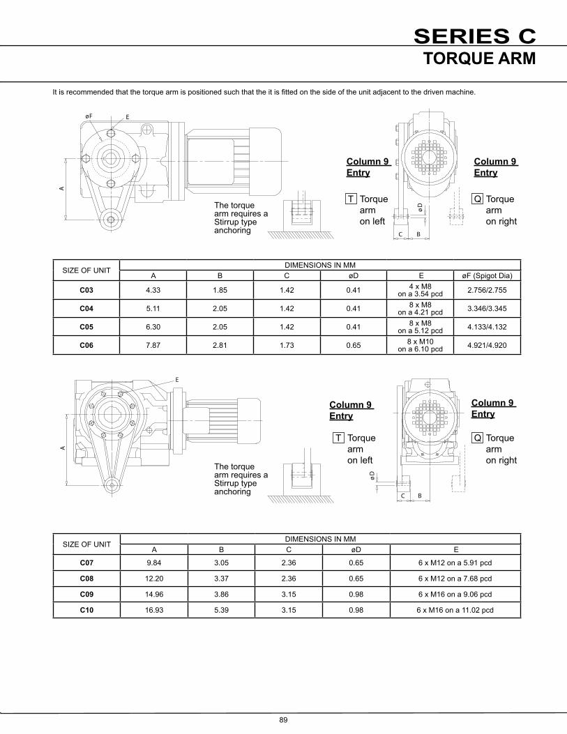
SERIES C
89
B
B
C
Dø
C
Dø
E
E
E
øF
AA
A
Dø
BC
The torquearm requires aStirrup typeanchoring
T Torquearmon left
Q Torquearmon right
T Torquearmon left
Q Torquearmon right
T Torquearmon left
Q Torquearmon right
The torquearm requires aStirrup typeanchoring
The torquearm requires aStirrup typeanchoring
B
B
C
Dø
C
Dø
E
E
E
øF
AA
A
Dø
BC
The torquearm requires aStirrup typeanchoring
T Torquearmon left
Q Torquearmon right
T Torquearmon left
Q Torquearmon right
T Torquearmon left
Q Torquearmon right
The torquearm requires aStirrup typeanchoring
The torquearm requires aStirrup typeanchoring
It is recommended that the torque arm is positioned such that the it is fitted on the side of the unit adjacent to the driven machine.
SIZE OF UNITDIMENSIONS IN MM
A B C �D E �F (Spigot Dia)
C03 4.33 1.85 1.42 0.41 4 x M8 on a 3.54 pcd 2.756/2.755
C04 5.11 2.05 1.42 0.41 8 x M8 on a 4.21 pcd 3.346/3.345
C05 6.30 2.05 1.42 0.41 8 x M8 on a 5.12 pcd 4.133/4.132
C06 7.87 2.81 1.73 0.65 8 x M10 on a 6.10 pcd 4.921/4.920
SIZE OF UNITDIMENSIONS IN MM
A B C �D E
C07 9.84 3.05 2.36 0.65 6 x M12 on a 5.91 pcd
C08 12.20 3.37 2.36 0.65 6 x M12 on a 7.68 pcd
C09 14.96 3.86 3.15 0.98 6 x M16 on a 9.06 pcd
C10 16.93 5.39 3.15 0.98 6 x M16 on a 11.02 pcd
Column 9 Entry
Column 9 Entry
Column 9 Entry
Column 9 Entry
TORQUE ARM

SERIES C
90
øe1
Mo
a3
t
ød
u
f1
i2
c1
o
ø1
b
ø1
a
L
L12 L11
øe1
Mo
Note: Flange units can besupplied as standard withan extended output shaftColumn 11 Entry F
Tapped Holev
Output Shaft
4 Holess1 dia
8 Holess1 dia
SIZE Standard Output Shaft - Column 11 Entry C
�d i 2 L L12 o t u v
C03 0.750/0.749 0.98 1.38 1.28 3.94 0.83 0.19 1/4” UNF
C04 1.000/0.999 1.14 1.81 1.69 4.53 1.1 0.25 1/4” UNF
C05 1.250/1.249 1.06 2.36 2.12 5.27 1.36 0.25 3/8” UNF
C06 1.375/1.374 1.57 2.48 2.34 6.30 1.51 0.32 1/2” UNF
C06Heavy Duty 1.750/1.749 2.95 3.86 3.75 7.68 1.92 0.37 5/8” UNF
C07 1.750/1.749 1.97 2.99 2.62 7.68 1.92 0.37 5/8” UNF
C08 2.375/2.374 3.35 4.72 4.12 10.04 2.64 0.63 3/4” UNF
C09 2.875/2.874 3.74 5.12 4.50 11.61 3.20 0.75 3/4” UNF
C10 3.625/3.624 5.28 6.69 5.87 14.41 4.00 0.87 1” UNF
SIZE �a1 a3 øb1 c1 �e1 f1 m �s1C03
Red Dia 4.72 2.95 3.15 j6 0.31 3.94 0.12 45° 0.26
C03 6.30 2.95 4.33 j6 0.40 5.12 0.16 45° 0.35
C04 6.30 3.39 4.33 j6 0.40 5.12 0.14 45° 0.35
C05 7.87 4.21 5.12 j6 0.47 6.50 0.14 45° 0.43
C06 7.87 4.72 5.12 j6 0.47 6.50 0.14 45° 0.43
C07 9.84 5.71 7.09 j6 0.47 8.46 0.16 45° 0.55
C08 13.78 6.69 9.84 h6 0.71 11.81 0.20 45° 0.71
C09 17.72 7.87 13.78 h6 0.79 15.75 0.20 22.5° 0.71
C10 17.72 9.13 13.78 h6 0.87 15.75 0.20 22.5° 0.71
Sizes C09 & C10 Sizes C03 to C08
Column 9 Entry F B5 (D) Output Flange on Left
Column 9 Entry H B5 (D) Output Flange on Right
DIMENSIONSD (B5) FLANGE

SERIES C
91
øQ
øe5
F7
22.5o
22.5 o
22.5o
22.5o
22.5o
22.5o
22.5o
22.5o
f
o2
ør
F
o2
øR
C04, C05, C06 & C08Eight hole pattern
Male spigotC03 - C06
Female recessC07 - C10
C03Four hole pattern
C07 & C09Six hole pattern
C10Ten hole pattern
SIZE �e5 F7 o2 Q �r h7spigot � �R H7 Spigot Recess
C03 3.54 pcd 4 Holes M8 0.87 Deep 2.24 4.17 2.76 - 0.16 -
C04 4.21 pcd 8 Holes M8 0.87 Deep 2.24 4.80 3.35 - 0.16 -
C05 5.12 pcd 8 Holes M8 0.87 Deep 2.44 5.75 4.13 - 0.16 -
C06 6.10 pcd 8 Holes M8 1.00 Deep 3.19 6.89 4.92 - 0.20 -
C07 5.91 pcd 8 Holes M8 0.87 Deep 4.09 7.09 - 5.12 - 0.18
C08 7.68 pcd 8 Holes M8 0.87 Deep 4.72 8.66 - 5.91 - 0.20
C09 9.06 pcd 8 Holes M8 1.00 Deep 5.67 11.02 - 7.09 - 0.20
C10 11.02 pcd 8 Holes M8 1.00 Deep 6.57 14.17 - 8.27 - 0.28
DIMENSIONSC (B14) FLANGE

SERIES C
92
V3
M o
ø3
C 6m
F2
øQ5
øR4 H7
9U
8U
8E
7E
6N 5A
3W
5N
D
6E
View on base
Tappedhole K2
AGITATOR - Non Standard Special Build.Please consult our Application Engineers
SIZE A5 C3 D E6 E7 �F2 K2 M N5 N6 Q5 R4 U8 U9 V3 W3
C07 6.30 2.50 11.42 5.12 4.53 4 x 0.59 on 10.43 pcd 5/8 UNF 45 4.29 5.87 11.81 9.055 0.24 0.63 2.77 0.625
C08 7.09 3.00 12.80 5.71 5.12 4 x 0.75 on 11.81 pcd 5/8 UNF 45 4.88 6.73 13.78 9.843 0.28 0.67 3.33 0.75
C09 7.87 3.50 14.17 6.30 5.71 4 x 0.75 on 13.78 pcd 5/8 UNF 45 5.59 7.56 15.75 11.811 0.28 0.79 3.88 0.875
C10 8.35 4.00 14.17 7.08 6.50 4 x 0.75 on 15.75 pcd 5/8 UNF 22.5 6.00 8.07 17.77 13.780 0.28 0.87 4.44 1.00
AGITATOR UNITS

SERIES C
93
SIZE Bore d da l l1 l2 l3 l4 l5 m N R T u u1
C03 inch 0.74970.7492
0.73 3.73 1.18 0.40 2.75 0.13 0.87 1/4 UNF 70lb.in 0.03R 0.644 0.638
0.188 0.187
0.03R
C04 inch 1.2486 1.2480
1.23 3.90 1.77 0.60 3.13 0.13 1.02 3/8 UNF 130lb.in 0.03R 1.11 1.10
0.250 0.249
0.03R
C05 inch 1.3746 1.3740
1.36 4.09 2.09 0.71 3.50 0.13 0.91 1/2 UNF 170lb.in 0.03R 1.20 1.19
0.312 0.311
0.03R
C06 inch 1.4996 1.4990
1.48 4.92 2.68 0.91 4.00 0.13 1.22 5/8 UNF 400lb.in 0.03R 1.29 1.28
0.375 0.374
0.03R
C07 inch 2.0000 1.9968
1.98 6.02 3.53 1.18 5.63 0.13 1.50 5/8 UNF 400lb.in 0.05R 1.72 1.71
0.500 0.499
0.05R
C08 inch 2.3750 2.3741
2.35 7.20 4.13 1.38 6.88 0.13 1.46 3/4 UNF 750lb.in 0.05R 2.02 2.01
0.625 0.624
0.05R
C09 inch 2.7500 2.7491
2.73 8.94 5.31 1.77 8.63 0.13 1.28 3/4 UNF 750lb.in 0.05R 2.40 2.39
0.625 0.624
0.05R
C10 inch 3.2500 3.2488
3.23 12.81 5.91 1.77 12.00 0.40 1.81 1 UNF 1700lb.in 0.05R 2.83 2.82
0.750 0.749
0.05R
ASSEMBLY ONTO SHAFT - CUSTOMERS SHAFT DETAIL
Assembly Instructions1. Spray the hollow shaft bore and mating diameter of the output shaft with Rocol DFSM or equivalent anti scuffing spray.
2. Fit key into shaft.
3. Fit the circlip into the output sleeve.
4. Fit the spacer tube only if the output shaft has no shoulder, then fit the output shaft into the output sleeve.
5. Secure in place with the washer and bolt. Torque tighten to the values stated in column N of the above table.
6. Fit plastic protective cover.
u
l3 l4
l1l2
l
T
u1
l5R
m
da dd
d
Spacer tube foruse withcustomer shaftwithout shoulder(Not supplied)
ProtectiveCover
Shaft with shoulder
Shaft without shoulder SpacerTube
For Dimensions for Metric Bore Units - consult Application Engineering
DIMENSIONSSTANDARD BORE ASSEMBLY

SERIES C
94
**
*
d3D
l2
1 x 45 o
m
u
d4
c6
c7
m1
d3
t
m1
d2
c4
SIZE Bore c4 c6 c7 D (H7) d2 d3 d4 l2 m m1 t u
C03 inch 0.20 0.40 0.50 0.75 0.3 0.745 0.45 4.75 0.12 3/8" UNF 0.63 0.187
C04 inch 0.20 0.60 0.65 1.25 0.5 1.245 0.88 6.50 0.12 5/8" UNF 1.10 0.25
C05 inch 0.20 0.60 0.65 1.375 0.5 1.370 1.00 6.50 0.12 5/8" UNF 1.19 0.312
C06 inch 0.20 0.80 0.90 1.50 0.85 1.495 1.13 8.75 0.12 1" UNF 1.28 0.375
C07 inch 0.31 1.00 1.10 2.00 1.05 1.995 1.59 10.00 0.20 11/4" UNF 1.71 0.500
C08 inch 0.31 1.00 1.10 2.375 1.05 2.370 1.90 12.25 0.20 11/4" UNF 2.01 0.625
C09 inch 0.31 1.00 1.10 2.75 1.05 2.745 2.18 14.50 0.20 11/4" UNF 2.39 0.625
C10 inch 0.31 1.20 1.30 3.25 1.30 3.245 2.65 17.00 0.20 11/2" UNF 2.82 0.700
DISASSEMBLY METHOD FROM SHAFT
* PARTS SUPPLIED BY CUSTOMER
DIMENSIONSSTANDARD BORE DISASSEMBLY

SERIES C
95
BASE MOUNT UNITS WITH STANDARD HOLLOW SHAFT
ALL WEIGHTS IN LB’S ALL WEIGHTS EXCLUDE LUBRICANT AND ARE FOR STANDARD SHAFT MOUNT UNITS, FOR BASE MOUNT UNITS ADD WEIGHT OF SHAFT (SHOWN AT TOP OF TABLE) TO THE FIGURES SHOWN ABOVE
SHIPPING SPECIFICATION
UNIT SIZE AND TYPEC
0321
C03
31
C03
41
C04
21
C04
31
C04
41
C05
21
C05
31
C05
41
C06
21
C06
31
C06
41
C07
21
C07
31
C07
41
C08
21
C08
41
C09
21
C09
41
C10
21
C10
41
Reducer Version 25 33 45 34 42 52 42 50 62 76 88 101 163 179 185 260 310 400 460 635 720
Output Shaft 1 2.2 3.3 7 15 26 41 66
MO
TOR
IZE
D U
NIT
S
56CWithout Motor 27 34 44 33 41 53 38 46 64 70 83 97 157 178 183 266 315 - 450 - 820
Including Motor 52 59 69 58 66 78 63 71 89 95 108 122 182 203 208 291 340 - 475 - 845
143TCWithout Motor 27 34 44 33 41 53 38 46 64 70 83 97 157 178 183 266 315 - 450 - 820
Including Motor 57 64 74 63 71 83 68 76 94 100 113 127 187 208 213 296 345 - 480 - 850
145TCWithout Motor 27 34 44 33 41 53 38 46 64 70 83 97 157 178 183 266 315 - 450 - 820
Including Motor 67 74 84 73 81 93 78 86 104 110 123 137 197 218 223 306 355 - 490 - 860
182TCWithout Motor 29 37 - 36 44 - 41 49 - 85 86 - 170 193 - 266 320 396 460 612 825
Including Motor 84 92 - 91 99 - 96 104 - 140 141 - 225 248 - 321 375 451 515 667 880
184TCWithout Motor 29 37 - 36 44 - 41 49 - 85 86 - 170 193 - 266 320 396 460 612 825
Including Motor 106 114 - 113 121 - 118 126 - 162 163 - 247 270 - 343 397 473 537 689 880
213TCWithout Motor - - - - - - - - - 85 - - 170 193 - 266 320 396 460 612 825
Including Motor - - - - - - - - - 201 - - 286 309 - 382 436 512 576 728 941
215TCWithout Motor - - - - - - - - - 85 - - 170 193 - 266 320 396 460 612 825
Including Motor - - - - - - - - - 242 - - 327 - - 423 477 553 617 769 982
254TCWithout Motor - - - - - - - - - - - - 170 - - 266 - 412 - 631 -
Including Motor - - - - - - - - - - - - 453 - - 549 - 695 - 914 -
256TCWithout Motor - - - - - - - - - - - - 170 - - 266 - 412 - 631 -
Including Motor - - - - - - - - - - - - 476 - - 572 - 718 - 937 -
284TCWithout Motor - - - - - - - - - - - - - - - - 417 - 636 -
Including Motor - - - - - - - - - - - - - - - - 846 - 1065 -
286TCWithout Motor - - - - - - - - - - - - - - - - 417 - 636 -
Including Motor - - - - - - - - - - - - - - - - 863 - 1082 -
324TCWithout Motor - - - - - - - - - - - - - - - - 421 - 650 -
Including Motor - - - - - - - - - - - - - - - - 944 - 1173 -
326TCWithout Motor - - - - - - - - - - - - - - - - 421 - 650 -
Including Motor - - - - - - - - - - - - - - - - 1071 - 1300 -
WEIGHT’S (LB’s) FOR STANDARD UNITS WITH HOLLOW SHAFT.
For units with Solid Output Shaft - Add the Weight of Shaft

SERIES C
96
IMPORTANTProduct Safety InformationGeneral - The following information is important in ensuring safety. It must be brought to the attention of personnel involved in the selection of the equipment, those responsible for the design of the machinery in which it is to be incorporated and those involved in its installation, use and maintenance.
The equipment will operate safely provided it is selected, installed, used and maintained properly. As with any power transmission equipment proper precautions must be taken as indicated in the following paragraphs, to ensure safety.
Potential Hazards - these are not necessarily listed in any order of severity as the degree of danger varies in individual circumstances. It is important therefore that the list is studied in its entirety:-
1) Fire/Explosion(a) Oil mists and vapour are generated within gear units. It is therefore dangerous to use naked lights in the proximity of gearbox openings, due to
the risk of fire or explosion.(b) In the event of fire or serious overheating (over 300 oC), certain materials (rubber, plastics, etc.) may decompose and produce fumes. Care
should be taken to avoid exposure to the fumes, and the remains of burned or overheated plastic/rubber materials should be handled with rubber gloves.
2) Guards - Rotating shafts and couplings must be guarded to eliminate the possibility of physical contact or entanglement of clothing. It should be of rigid construction and firmly secured.
3) Noise - High speed gearboxes and gearbox driven machinery may produce noise levels which are damaging to the hearing with prolonged exposure. Ear defenders should be provided for personnel in these circumstances. Reference should be made to the Department of Employment Code of Practice for reducing exposure of employed persons to noise.
4) Lifting - Where provided (on larger units) only the lifting points or eyebolts must be used for lifting operations (see maintenance manual or general arrangement drawing for lifting point positions). Failure to use the lifting points provided may result in personal injury and/or damage to the product or surrounding equipment. Keep clear of raised equipment.
5) Lubricants and Lubrication(a) Prolonged contact with lubricants can be detrimental to the skin. The manufacturer's instruction must be followed when handling lubricants.(b) The lubrication status of the equipment must be checked before commissioning. Read and carry out all instructions on the lubricant plate
and in the installation and maintenance literature. Heed all warning tags. Failure to do so could result in mechanical damage and in extreme cases risk of injury to personnel.
6) Electrical Equipment - Observe hazard warnings on electrical equipment and isolate power before working on the gearbox or associated equipment, in order to prevent the machinery being started.
7) Installation, Maintenance and Storage (a) In the event that equipment is to be held in storage, for a period exceeding 6 months, prior to installation or commissioning, application
engineering must be consulted regarding special preservation requirements. Unless otherwise agreed, equipment must be stored in a building protected from extremes of temperature and humidity to prevent deterioration.
The rotating components (gears and shafts) must be turned a few revolutions once a month (to prevent bearings brinelling).(b) External gearbox components may be supplied with preservative materials applied, in the form of a "waxed" tape overwrap or wax film
preservative. Gloves should be worn when removing these materials. The former can be removed manually, the latter using white spirit as a solvent.
Preservatives applied to the internal parts of the gear units do not require removal prior to operation.(c) Installation must be performed in accordance with the manufacturer's instructions and be undertaken by suitably qualified personnel.(d) Before working on a gearbox or associated equipment, ensure that the load has been removed from the system to eliminate the
possibility of any movement of the machinery and isolate power supply. Where necessary, provide mechanical means to ensure the machinery cannot move or rotate. Ensure removal of such devices after work is complete.
(e) Ensure the proper maintenance of gearboxes in operation. Use only the correct tools and approved spare parts for repair and maintenance. Consult the Maintenance Manual before dismantling or performing maintenance work.
8) Hot Surfaces and Lubricants(a) During operation, gear units may become sufficiently hot to cause skin burns. Care must be taken to avoid accidental contact.
(b) After extended running the lubricant in gear units and lubrication systems may reach temperatures sufficient to cause burns. Allow equipment to cool before servicing or performing adjustments.
9) Selection and Design(a) Where gear units provide a backstop facility, ensure that back-up systems are provided if failure of the backstop device would endanger
personnel or result in damage.(b) The driving and driven equipment must be correctly selected to ensure that the complete machinery installation will perform satisfactorily,
avoiding system critical speeds, system torsional vibration, etc.(c) The equipment must not be operated in an environment or at speeds, powers, torques or with external loads beyond those for which it was
designed.(d) As improvements in design are being made continually the contents of this catalogue are not to be regarded as binding in detail, and drawings
and capacities are subject to alterations without notice.
The above guidance is based on the current state of knowledge and our best assessment of the potential hazards in the operation of the gear units.
Any further information or clarification required may be obtained by contacting an Application Engineer.

www.benzlers.com
www.radicon.com
AUSTRALIA
Radicon Transmission (Australia) PTY Ltd
AustraliaTel: +61 421 822 315
EUROPE
Benzler TBA BVJachthavenweg 2 NL-5928 NT Venlo
GermanyTel: 0800 350 40 00Fax: 0800 350 40 01
ItalyTel: +39 02 824 3511
Netherlands & the rest of EuropeTel: +31 77 324 59 00Fax: +31 77 324 59 01
INDIA
Elecon. Engineering Company Ltd.Anand Sojitra RoadVallabh Vidyanagar388120 GujaratIndia
Tel: +91 2692 236513
DENMARK
Benzler Transmission A/SDalager 1DK-2605 Brøndby, Denmark
Tel: +45 36 34 03 00Fax: +45 36 77 02 42
FINLAND
Oy Benzler ABVanha Talvitie 3CFI-00580 Helsingfors, Finland
Tel: +358 9 340 1716Fax: +358 10 296 2072
SWEDEN & NORWAY
AB BenzlersPorfyrgatan254 68 HelsingborgSweden
Tel: +46 42 18 68 00Fax: +46 42 21 88 03
THAILAND
Radicon Transmission (Thailand) Ltd700/43 Moo 6Amata Nakorn Industrial EstateTumbol KlongtumruMuang, Chonburi 20000Thailand
Tel: +66 3845 9044Fax: +66 3821 3655
UNITED KINGDOM
Radicon Transmission UK LtdUnit J3Lowfields Business Park, Lowfields Way, EllandWest Yorkshire, HX5 9DA
Tel: +44 1484 465 800 Fax: +44 1484 465 801
USA
Radicon Drive Systems, Inc.2475 Alft Lane ElginChicagoIllinois60124USA
Tel: +1 847 593 9910Fax: +1 847 593 9950
CONTACT US

Benzlers
Denmark +45 36 340300Finland +358 9 3401716Germany +49 800 3504000 Italy +39 02 824 3511Sweden +46 42 186800The Netherlands +31 77 3245900www.benzlers.com
Radicon
Thailand +66 38459044 United Kingdom +44 1484 465800USA +1 847 5939910www.radicon.com


![Helical wormgear units S - SEM-POLSKAsempolska.com.pl/wp-content/uploads/2015/09/keb-przekladnie-s.pdf · Helical worm gear units S 61 Selection table -Gear units i T2max [Nm] P1max](https://static.fdocuments.us/doc/165x107/60e6bebe678ebc462446246c/helical-wormgear-units-s-sem-helical-worm-gear-units-s-61-selection-table-gear.jpg)