Series and Parallel Circuits 1 Lesson 9 November 17 th, 2010.
34
Series and Parallel Series and Parallel Circuits 1 Circuits 1 Lesson 9 November 17 th , 2010
-
Upload
amberly-fitzgerald -
Category
Documents
-
view
218 -
download
0
Transcript of Series and Parallel Circuits 1 Lesson 9 November 17 th, 2010.
Series and Parallel Series and Parallel Circuits 1Circuits 1Lesson 9November 17th, 2010
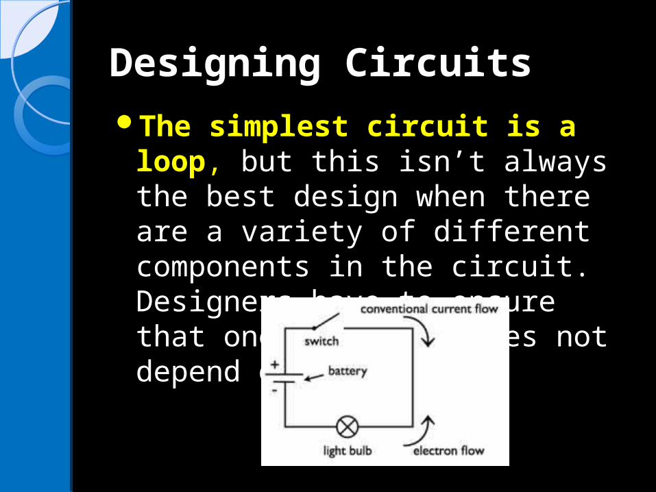
Designing CircuitsDesigning CircuitsThe simplest circuit is a loop,
but this isn’t always the best design when there are a variety of different components in the circuit. Designers have to ensure that one component does not depend on another.
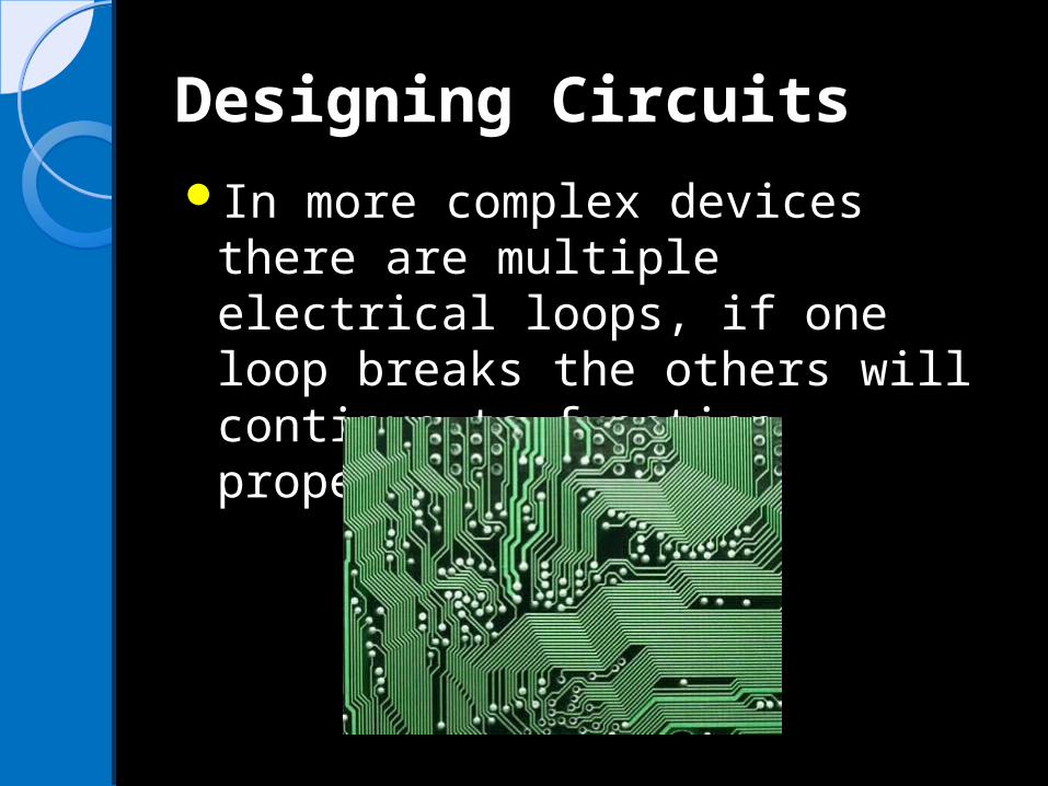
Designing CircuitsDesigning CircuitsIn more complex devices there
are multiple electrical loops, if one loop breaks the others will continue to function properly.

Tiny CircuitsTiny CircuitsConventional switches and other
electrical components are practical and convenient for homes or simple, large electrical devices. Miniature circuits in advanced electronic devices require transistors instead.
A transistor is a tiny device that acts as a switch or amplifier in a circuit. ◦Often referred to as solid-state components
because they are made of solid material with no moving parts.
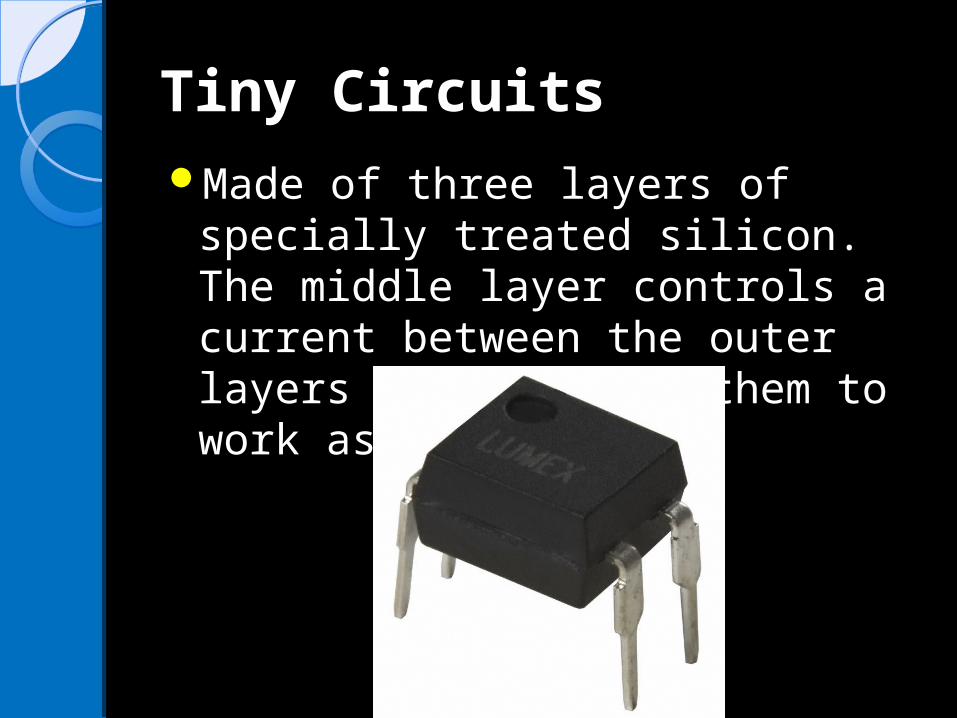
Tiny CircuitsTiny CircuitsMade of three layers of specially
treated silicon. The middle layer controls a current between the outer layers which allows them to work as switches.
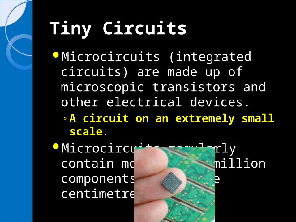
Tiny CircuitsTiny CircuitsMicrocircuits (integrated circuits)
are made up of microscopic transistors and other electrical devices. ◦A circuit on an extremely small scale.
Microcircuits regularly contain more than a million components per square centimetre
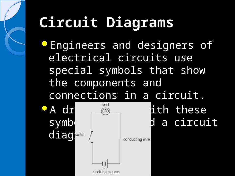
Circuit DiagramsCircuit DiagramsEngineers and designers of
electrical circuits use special symbols that show the components and connections in a circuit.
A drawing made with these symbols is called a circuit diagram.
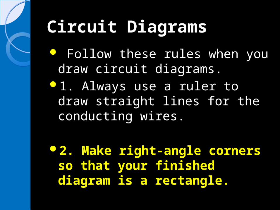
Circuit DiagramsCircuit Diagrams Follow these rules when you
draw circuit diagrams.1. Always use a ruler to draw
straight lines for the conducting wires.
2. Make right-angle corners so that your finished diagram is a rectangle.

Electric Circuit Diagrams Electric Circuit Diagrams and Symbolsand SymbolsConductor or wire
◦To pass current very easily from one part of a circuit to another.
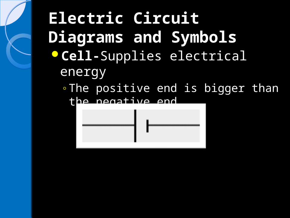
Electric Circuit Diagrams Electric Circuit Diagrams and Symbolsand SymbolsCell-Supplies electrical energy
◦The positive end is bigger than the negative end.

Electric Circuit Diagrams Electric Circuit Diagrams and Symbolsand Symbols2 CellsNote: every time a cell is added
you need to draw another cell.
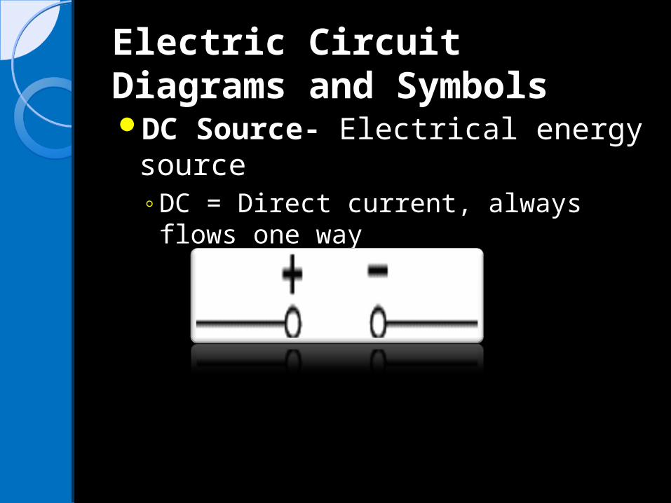
Electric Circuit Diagrams Electric Circuit Diagrams and Symbolsand SymbolsDC Source- Electrical energy
source◦DC = Direct current, always flows
one way

Electric Circuit Diagrams Electric Circuit Diagrams and Symbolsand SymbolsAC Source - Electrical energy
sourceAC = Alternating current,
continually changing direction

Electric Circuit Diagrams Electric Circuit Diagrams and Symbolsand SymbolsGround –
◦A connection to earth
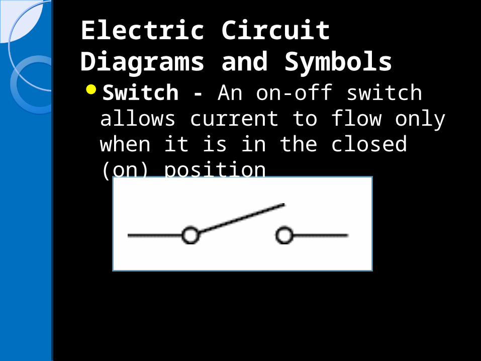
Electric Circuit Diagrams Electric Circuit Diagrams and Symbolsand SymbolsSwitch - An on-off switch allows
current to flow only when it is in the closed (on) position
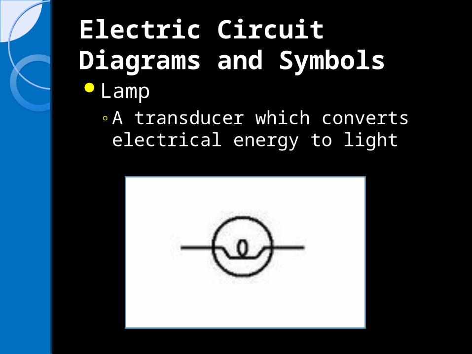
Electric Circuit Diagrams Electric Circuit Diagrams and Symbolsand SymbolsLamp
◦A transducer which converts electrical energy to light
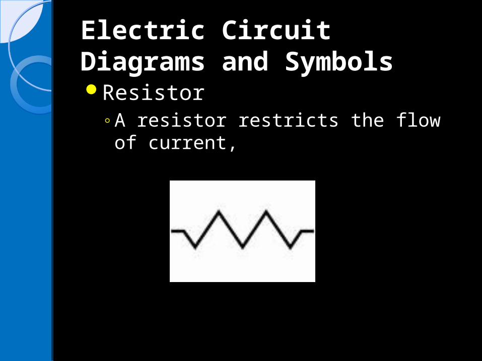
Electric Circuit Diagrams Electric Circuit Diagrams and Symbolsand SymbolsResistor
◦A resistor restricts the flow of current,

Electric Circuit Diagrams Electric Circuit Diagrams and Symbolsand SymbolsAmmeter
◦-Device that measures current
A

Electric Circuit Diagrams Electric Circuit Diagrams and Symbolsand SymbolsVoltmeter-Device that measures voltage
V

Electric Circuit Diagrams Electric Circuit Diagrams and Symbolsand SymbolsMotor -electrical load that
converts electrical energy into movement
M

Series Circuits Series Circuits Electric circuit in
which the components are arranged one after another in series.
A series circuit has only one path along which electrons can flow.
If that pathway is interrupted, the whole circuit cannot function.

Series Circuits Series Circuits The amount of current is the
same in all parts of a series circuit.
If more resistors are added, it will increase the total resistance of the circuit.
This decreases the current.

Series Circuits Series Circuits Example: Adding an extra bulb to a
series string of lights makes all the bulbs dimmer.
Electrons use up all their potential difference going around a series circuit no matter how many loads are in the circuit. Each load will use part of the total potential difference, depending on how much it resists the flow of electrons.
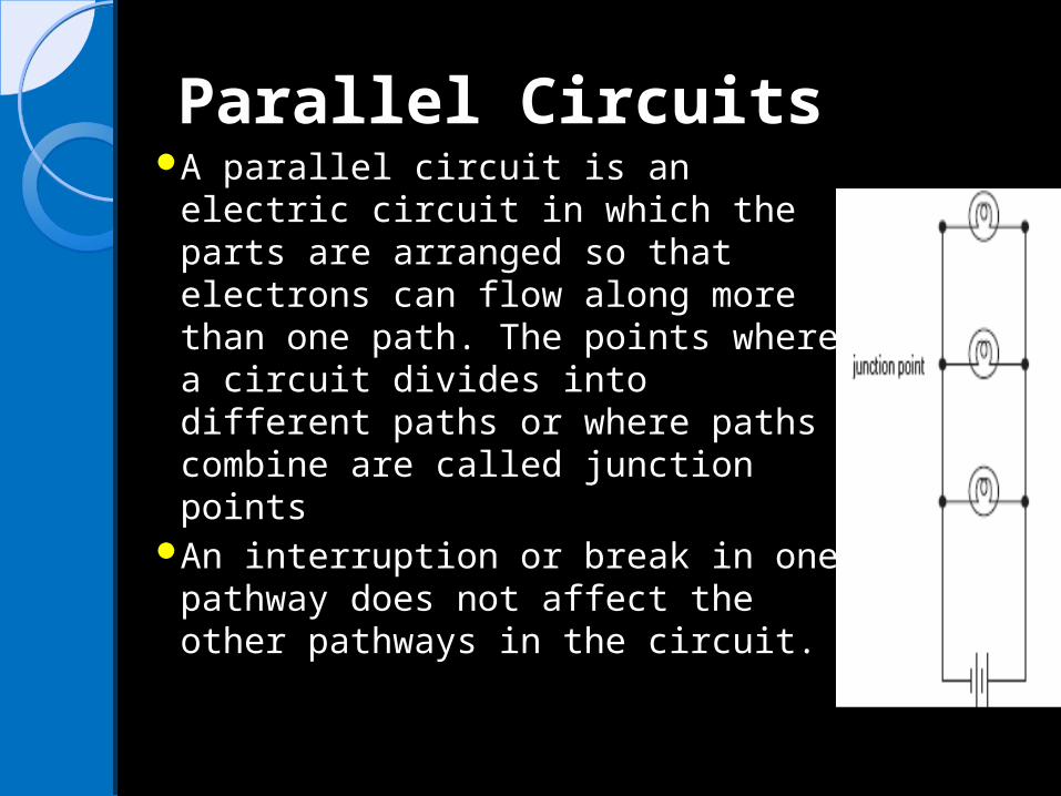
Parallel CircuitsParallel CircuitsA parallel circuit is an electric
circuit in which the parts are arranged so that electrons can flow along more than one path. The points where a circuit divides into different paths or where paths combine are called junction points
An interruption or break in one pathway does not affect the other pathways in the circuit.

Parallel CircuitsParallel CircuitsSimilarly, adding a new pathway
with more resistors does not affect the resistance in any of the other pathways. Adding extra resistors in parallel decreases the total resistance of the circuit.
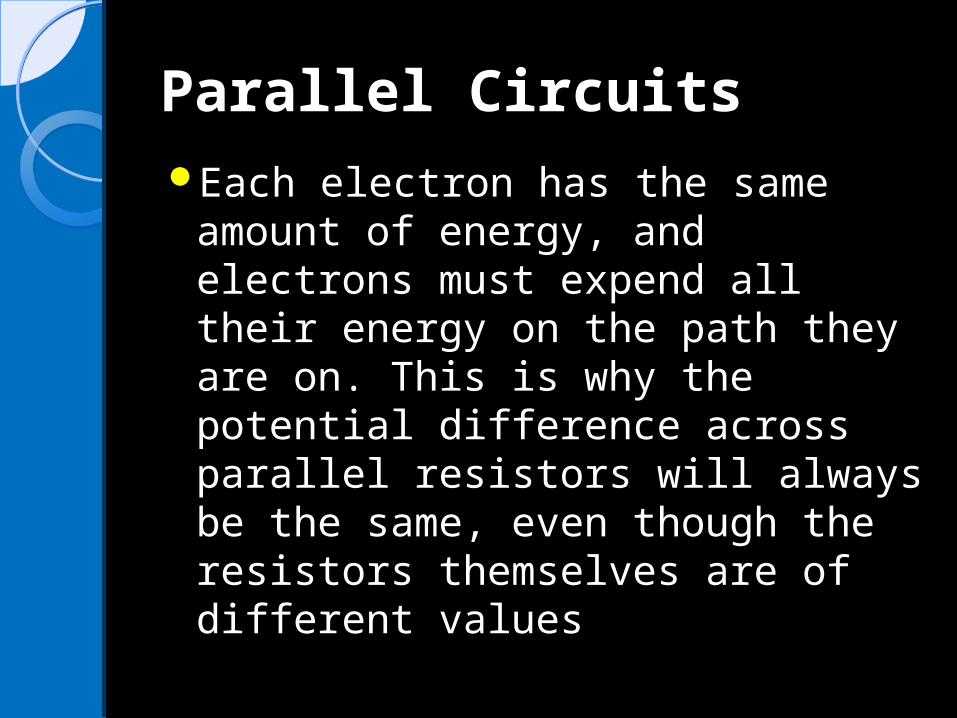
Parallel CircuitsParallel CircuitsEach electron has the same
amount of energy, and electrons must expend all their energy on the path they are on. This is why the potential difference across parallel resistors will always be the same, even though the resistors themselves are of different values

Loads connected in parallel circuits have different currents

Summary of Current, Summary of Current, potential difference, and potential difference, and resistance in series and resistance in series and parallel circuits. parallel circuits.
Circuit Potential DifferenceSeries circuit
Each load uses a portion of the total potential differences supplies by the battery
Parallel circuit
Each load uses all the potential difference supplied by the battery.
Summary of Current, Summary of Current, potential difference, and potential difference, and resistance in series and resistance in series and parallel circuits. parallel circuits.
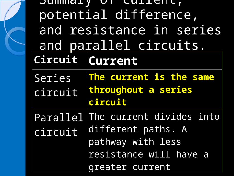
Circuit Current
Series circuit
The current is the same throughout a series circuit
Parallel circuit
The current divides into different paths. A pathway with less resistance will have a greater current
Summary of Current, Summary of Current, potential difference, and potential difference, and resistance in series and resistance in series and parallel circuits. parallel circuits.
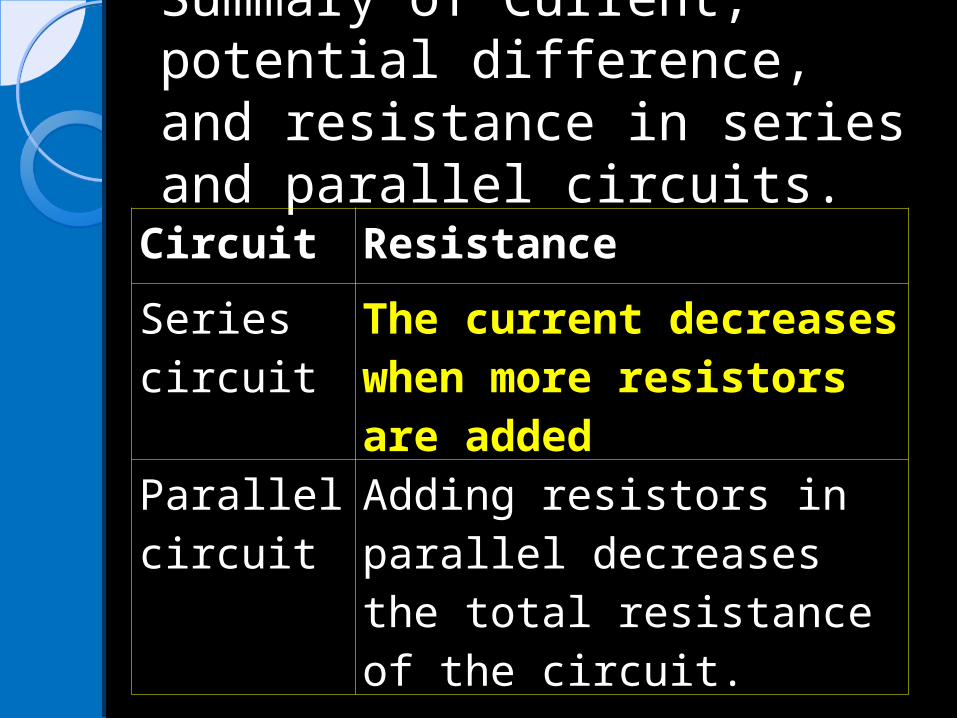
Circuit Resistance
Series circuit
The current decreases when more resistors are added
Parallel circuit
Adding resistors in parallel decreases the total resistance of the circuit.

Two Types of Circuits Two Types of Circuits Combined Combined Series circuits and parallel
circuits make up the circuits in your home and school.

Two Types of Circuits Two Types of Circuits Combined Combined Some circuits are combinations
of series circuits and parallel circuits. These combinations help prevent problems such as the all the lights in the house going out because one bulb burnt out.

It is also an important safety feature in a combination circuit to have some switches wired in series, because it is sometimes necessary to turn off the electricity in part or all of a home

Questions U3 L9Questions U3 L9Draw a circuit diagram for a circuit that includes a
resistor, a switch, conducting wires, and a battery. C (1)
Draw a circuit diagram of a series circuit with a battery, connecting wires, and one light bulb. C (1)
Draw a circuit diagram of a parallel circuit with a battery, connecting wires and two light bulbs. C (1)
What happens to the voltage in a series circuit when more loads are added? I (1)
What happens to the current in a parallel circuit when more loads are added? I (1)
How do combination circuits help prevent problems in circuits in a home? I (1)