Series & Parallel Circuits
13
Series & Parallel Circuits Question Paper 1 Time allowed: 46 minutes Score: /46 Percentage: /100 Grade Boundaries: Level GCSE Subject Physics Exam Board AQA Topic Electricity Sub-topic Series & Parallel Circuits Booklet Question Paper 1 9 8 7 6 5 4 3 >72% 63% 54% 45% 35% 26% 21% 1 Copyright © 2020 Save My Exams Ltd. All rights reserved. For more awesome resources, visit us at www.savemyexams.co.uk/
Transcript of Series & Parallel Circuits

Series & Parallel Circuits Question Paper 1
Time allowed: 46 minutes
Score: /46
Percentage: /100
Grade Boundaries:
Level GCSE
Subject Physics
Exam Board AQA
Topic Electricity
Sub-topic Series & Parallel Circuits
Booklet Question Paper 1
9 8 7 6 5 4 3 >72% 63% 54% 45% 35% 26% 21%
1 Copyright © 2020 Save My Exams Ltd. All rights reserved.
For more awesome resources, visit us at www.savemyexams.co.uk/

Q1.
(a) The circuit in Figure 1 shows how an LDR can be used to turn on a circuit when itgets dark.
Figure 1
If the light intensity decreases, what happens to the current and the potential difference across the LDR?
[2 marks]
Potential difference ____________________________________________
Current ______________________________________________________
(b) When the potential difference across the LDR is 3 V, what is its resistance?
Explain your answer.
[2 marks]
Resistance = ________________ Ω
Reason ___________________________________________________________
__________________________________________________________________
2 Copyright © 2020 Save My Exams Ltd. All rights reserved.
For more awesome resources, visit us at www.savemyexams.co.uk/

(c) When the light gets dimmer, the resistance of the LDR becomes 1000 .Ω
Calculate the current through the LDR when its resistance is 1000 .Ω
Give your answer to 3 significant figures.[4 marks]
_________________________________________________________________
_________________________________________________________________
_________________________________________________________________
_________________________________________________________________
Current = ______________ A
[Question Total: 8 marks]
3 Copyright © 2020 Save My Exams Ltd. All rights reserved.
For more awesome resources, visit us at www.savemyexams.co.uk/
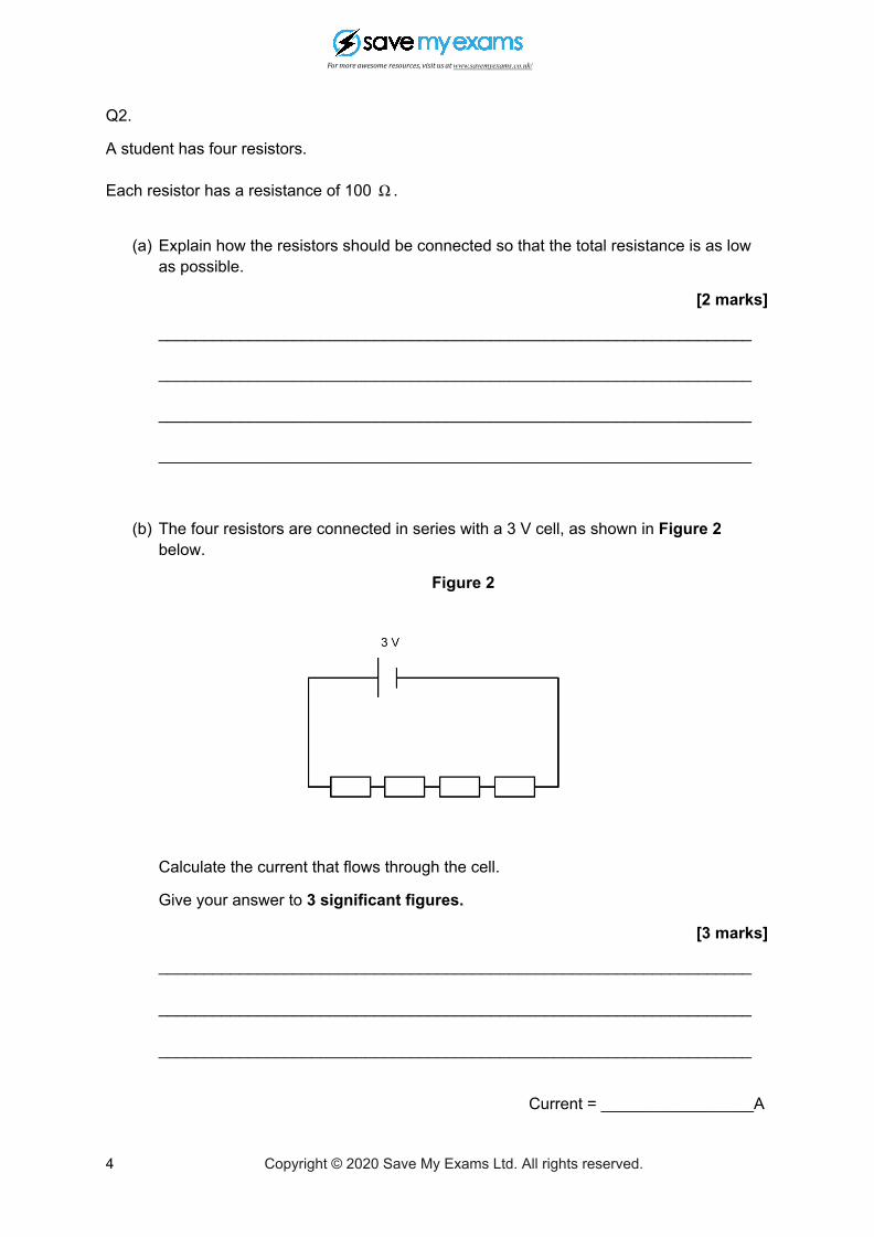
Q2.
A student has four resistors.
Each resistor has a resistance of 100 .Ω
(a) Explain how the resistors should be connected so that the total resistance is as lowas possible.
[2 marks]
__________________________________________________________________
__________________________________________________________________
__________________________________________________________________
__________________________________________________________________
(b) The four resistors are connected in series with a 3 V cell, as shown in Figure 2below.
Figure 2
Calculate the current that flows through the cell.
Give your answer to 3 significant figures.
[3 marks]
__________________________________________________________________
__________________________________________________________________
__________________________________________________________________
Current = _________________A
4 Copyright © 2020 Save My Exams Ltd. All rights reserved.
For more awesome resources, visit us at www.savemyexams.co.uk/

(c) Add an ammeter to Figure 2 which would allow the current through the cell to bemeasured.
[2 marks]
[Question total: 7 marks]
5 Copyright © 2020 Save My Exams Ltd. All rights reserved.
For more awesome resources, visit us at www.savemyexams.co.uk/

Q3.
A student set up the circuit in Figure 3 below.
Figure 3
(a) The ammeter displays a reading of 0.075 A.
Calculate the potential difference across the 80 resistor.Ω[2 marks]
__________________________________________________________________
__________________________________________________________________
Potential difference ___________________ V
(b) Calculate the resistance of resistor R in Figure 3.[3 marks]
__________________________________________________________________
__________________________________________________________________
__________________________________________________________________
Resistance = _____________ Ω
6 Copyright © 2020 Save My Exams Ltd. All rights reserved.
For more awesome resources, visit us at www.savemyexams.co.uk/

(c) Switch X is closed.
State what will happen to the total resistance of the circuit and the current throughthe circuit.
[2 marks]
__________________________________________________________________
__________________________________________________________________
__________________________________________________________________
__________________________________________________________________
(d) Calculate the new current through the circuit.[3 marks]
__________________________________________________________________
__________________________________________________________________
__________________________________________________________________
Current = ________________ A
[Question total: 10 marks]
7 Copyright © 2020 Save My Exams Ltd. All rights reserved.
For more awesome resources, visit us at www.savemyexams.co.uk/

Q4.
Figure 4 below shows how two resistors can be connected in series or in parallel to a 12 V cell.
The resistors are identical.
Figure 4
(a) Calculate the potential difference across each resistor when the lamps are connectedin series and in parallel.
[2 marks]
In series __________________________________________________________
_________________________________________________________________
In parallel _________________________________________________________
_________________________________________________________________
(b) Give one disadvantage of connecting the lamps in series rather than in parallel.[1 mark]
__________________________________________________________________
__________________________________________________________________
8 Copyright © 2020 Save My Exams Ltd. All rights reserved.
For more awesome resources, visit us at www.savemyexams.co.uk/

Figure 5 shows how an ammeter can be used to measure the current flowing through the battery for the same circuit.
Figure 5
The reading on the ammeter is 1.6 A.
(c) Add an ammeter to Figure 5 to show how to measure the current through resistor R2.
[1 mark]
(d) The resistors are identical.
State the current through resistor R2.[1 mark]
__________________________________________________________________
__________________________________________________________________
[Question total: 5 marks]
9 Copyright © 2020 Save My Exams Ltd. All rights reserved.
For more awesome resources, visit us at www.savemyexams.co.uk/

Q5.
Figure 6 shows a fixed resistor connected in series with a variable resistor.
Figure 6
The resistance of the variable resistor can be varied between 100 and 800 .Ω Ω
The graph below in Figure 7 shows how the readings on both voltmeters vary as the resistance of the variable resistance is changed.
Figure 7
10 Copyright © 2020 Save My Exams Ltd. All rights reserved.
For more awesome resources, visit us at www.savemyexams.co.uk/

(a) Calculate the potential difference of the battery.[2 marks]
__________________________________________________________________
__________________________________________________________________
Potential difference = __________________ V
(b) Use the graph in Figure 7 to determine the resistance of the fixed resistor R in thecircuit shown in Figure 6.
[2 marks]
__________________________________________________________________
__________________________________________________________________
__________________________________________________________________
Resistance = ___________ Ω
(c) Add an ammeter to Figure 6 above to show how the current through the circuit couldbe measured.
[1 mark]
(d) Calculate the current through the circuit when the resistance of the variable resistor isset to 400 .Ω
[3 marks]
__________________________________________________________________
__________________________________________________________________
__________________________________________________________________
__________________________________________________________________
Current = _____________ A
[Question total: 8 marks]
11 Copyright © 2020 Save My Exams Ltd. All rights reserved.
For more awesome resources, visit us at www.savemyexams.co.uk/

Q6.
The circuit diagram in Figure 8 shows two resistors connected in parallel.
Figure 8
Reading on ammeter A1 = 3 A
Reading on ammeter A2 = 1 A
Using the circuit diagram in Figure 8, answer the questions below:
(a) What is the potential difference across resistor R1?[1 mark]
potential difference = ___________________ V
(b) Calculate the resistance of resistor R1.[2 marks]
__________________________________________________________________
__________________________________________________________________
Resistance = ______________ Ω
(c) What is the current flowing through the variable resistor R2?[1 mark]
12 Copyright © 2020 Save My Exams Ltd. All rights reserved.
For more awesome resources, visit us at www.savemyexams.co.uk/

Current = ___________________ A
(d) Calculate the resistance of the variable resistor R2.[1 mark]
__________________________________________________________________
__________________________________________________________________
Resistance = __________________ Ω
(e) The resistance of the variable resistor R2 is increased.
What would happen to:
● The current through R2● The potential difference across R2● The current through the battery?
Tick ( ) three boxes [3 marks]
Increase Stay the same Decrease
Current through R2
potential difference across R2
current through the battery
[Question total: 8 marks]
13 Copyright © 2020 Save My Exams Ltd. All rights reserved.
For more awesome resources, visit us at www.savemyexams.co.uk/