Series 93 User’s Manual - Instrumentation...
52
Series 93 1/16 DIN Microprocessor-Based Auto-tuning Control 0600-0001-0000 Rev C Made in the U.S.A. February 1999 $10 Supersedes 0600-0001-0000 Rev B User’s Manual Watlow Controls 1241 Bundy Blvd., P.O. Box 5580, Winona, Minnesota USA 55987-5580 Phone: (507) 454-5300, Fax: (507) 452-4507 http://www.watlow.com Registered Company Winona, Minnesota USA ISO 9001 97 TOTAL 3 Year Warranty CUSTOMER SATISFACTION User Levels: • New User . . . . . . . . . . . . . . . . . . . . . . . . . . .go to page 1.1 • Experienced User . . . . . . . . . . . . . . . . . . . . .go to page 2.1 • Expert user . . . . . . . . . . . . . . . . . . . . . . . . . .go to page 2.1 Installers: • Installation . . . . . . . . . . . . . . . . . . . . . . . . . .go to page 2.1 • Wiring . . . . . . . . . . . . . . . . . . . . . . . . . . . . . .go to page 2.3 Recycled Paper At Least 10% Postconsumer Waste
Transcript of Series 93 User’s Manual - Instrumentation...

Series 93
1/16 DIN Microprocessor-BasedAuto-tuning Control
0600-0001-0000 Rev C Made in the U.S.A.February 1999 $10Supersedes 0600-0001-0000 Rev B
User’s Manual
Watlow Controls1241 Bundy Blvd., P.O. Box 5580, Winona, Minnesota USA 55987-5580
Phone: (507) 454-5300, Fax: (507) 452-4507 http://www.watlow.com
Registered Company Winona, Minnesota USA
ISO 9001
97TOTAL
3 Year Warranty
CUSTOMERSATISFACTION
User Levels:• New User . . . . . . . . . . . . . . . . . . . . . . . . . . .go to page 1.1• Experienced User . . . . . . . . . . . . . . . . . . . . .go to page 2.1• Expert user . . . . . . . . . . . . . . . . . . . . . . . . . .go to page 2.1Installers:• Installation . . . . . . . . . . . . . . . . . . . . . . . . . .go to page 2.1• Wiring . . . . . . . . . . . . . . . . . . . . . . . . . . . . . .go to page 2.3
Recycled Paper At Least 10% Postconsumer Waste
READ ME
For best printing results, check these settings in your print set-up dialog box. * Color/Grayscale * Dithering * Highest possible DPI (dots per inch) -------------------------------- For best on-screen viewing, set your display control panel to the highest resolution available.

How to Use This Manual Wat low Ser ies 93
Safety InformationWe use note, caution and warning symbols throughout this book to draw yourattention to important operational and safety information.
A bold text “NOTE” marks a short message in the margin to alert you to animportant detail.
A bold text “CAUTION” safety alert appears with information that is impor-tant for protecting your equipment and performance. Be especially careful toread and follow all cautions that apply to your application.
A bold text “WARNING” safety alert appears with information that is impor-tant for protecting you, others and equipment from damage. Pay very closeattention to all warnings that apply to your application.
The safety alert symbol, ç, (an exclamation point in a triangle) precedes ageneral CAUTION or WARNING statement.
The electrical hazard symbol, Ó, (a lightning bolt in a triangle) precedes anelectric shock hazard CAUTION or WARNING safety statement.
Technical AssistanceIf you encounter a problem with your Watlow controller, review all of your con-figuration information for each step of the setup, to verify that your selectionsare consistent with your applications. If the problem persists after checkingthe above, you can get technical assistance from your local Watlow representa-tive, or by dialing (507) 454-5300.
An applications engineer will discuss your application with you.
Please have the following information available when calling:
• Complete model number • All configuration information
• User’s Manual • Diagnostic Menu readings
Your FeedbackYour comments or suggestions on this manual are welcome, please send themto: Technical Writer, Watlow Controls, 1241 Bundy Blvd., P.O. Box 5580,Winona, MN 55987-5580, Phone: (507) 454-5300, Fax: (507) 452-4507. TheSeries 93 User’s Manual is copyrighted by Watlow Winona, Inc., © February1999, with all rights reserved. (1638)
NOTE:Details of a “Note”appear here in thenarrow margin onthe left side of eachpage.
çCAUTION:Details of a“Caution” appearhere in the narrowmargin on the leftside of each page.
ÓWARNING:Details of a“Warning” appearhere in the narrowmargin on the leftside of each page.

Watlow Ser ies 93 Table of Contents i
Chapter 1: Overview ......................................................... 1.1General Description ................................................ 1.1
Chapter 2: Install And Wire The Series 93 .................... 2.1Panel Cutout ............................................................2.1Dimensions ..............................................................2.1Installation Procedure ..............................................2.1Wiring the Series 93 ................................................2.3Power Wiring............................................................2.3Sensor Installation Guidelines .................................2.4Input Wiring .............................................................2.4Output 1 Wiring ...................................................... 2.6Output 2 Wiring ...................................................... 2.8System Wiring Example .......................................... 2.9
Chapter 3: How To Use The Keys And Displays ............ 3.1Keys, Displays and Indicator Lights ........................ 3.1
Chapter 4: How To Set Up The Series 93 ...................... 4.1Setting the Input Type DIP Switch .......................... 4.1Entering Setup Menu .............................................. 4.2Setup Parameters ................................................... 4.3Setup Menu Table ................................................... 4.5Operation Parameters ............................................. 4.6Operation Menu Table ............................................. 4.7
Chapter 5: How To Tune And Operate ........................... 5.1Autotuning .............................................................. 5.1Manual Tuning ........................................................ 5.2Manual and Automatic Operation ............................ 5.3Using Alarms .......................................................... 5.4Error Code Messages ............................................. 5.5Error Code Actions ...................................................5.6
Appendix ........................................................................ A.1Noise and Installation Guidelines .............................A.1Noise Sources .........................................................A.1Decreasing Noise Sensitivity ...................................A.1Eliminating Noise .................................................... A.2Entering the Calibration Menu .................................A.3Restoring Factory Calibration ................................. A.4Calibration Menu .................................................... A.4Calibration Procedures ........................................... A.5Glossary ................................................................. A.9Specifications ....................................................... A.12Model Number Information .................................. A.13Index .................................................................... A.14Declaration of Conformity.......................................A.15Quick Reference ................................................... A.17
Figures and Tables
Figures ...................................................... Page
Series 93 Input and Output Overview ..............................1.1Series 93 Multiple Panel Cutout Dimensions .................2.1aSeries 93 Dimensions ....................................................2.1bMounting, Case Side View ............................................. 2.2aMounting Collar ..............................................................2.2bCase Rear View and IP65 (NEMA 4X) Seal Example ..... 2.2cPower Wiring .................................................................. 2.3Thermocouple Sensor Input Wiring .............................. 2.4a2- or 3-wire RTD Sensor Input Wiring .......................... 2.4b0-5VÎ (dc) Process Sensor Input Wiring ..................... 2.5a4-20mA Process Sensor Input Wiring ...........................2.5bOutput 1 Mechanical Relay Wiring ................................ 2.6aOutput 1 Solid-state Relay w/o Suppression Wiring ..... 2.6bSwitched DC Output 1 Wiring ....................................... 2.7a4-20mA Process Wiring ............................................... 2.7bOutput 2 Mechanical Relay Wiring ................................ 2.8aOutput 2 Solid-state Relay w/o Suppression Wiring .....2.8bSwitched DC Output 2 Wiring ....................................... 2.8cSystem Wiring Example .................................................. 2.9Wiring Notes...................................................................2.10Series 93 Keys and Displays ........................................... 3.1DIP Switch Location and Orientation ............................ 4.1aInput DIP Switches .........................................................4.1bEntering the Setup Menu .............................................. 4.2aThe Setup Menu ........................................................... 4.2bThe Operation Menu ....................................................... 4.6Autotuning at a 200°F Set Point ..................................... 5.1Clearing an Alarm ........................................................... 5.4Error Code Message ....................................................... 5.5Entering the Calibration Menu ........................................ A.3Calibration Menu ............................................................ A.4
Tables ...................................................... Page
Input Ranges ................................................................. 4.5aSetup Menu Prompts and Descriptions ......................... 4.5bOperation Menu Prompts and Descriptions..................... 4.7Quick Reference Sheet .........................................A.17-A.18
TC Table of Contents

i i Table of Contents Wat low Ser ies 93
Meet the Series 93 Team TOTAL
3 Year Warranty
CUSTOMERSATISFACTION
We stand behind our product and are committed to your total satisfaction.Pictured below are some of the people at Watlow who have worked hard tobring you one of the finest industrial temperature controllers available today.Included in the photo are members of the development team, and representa-tives from our core manufacturing and customer service areas.
Front: Linda Florin, production; Nicole Smith, production; Trish Johnson,production; Sarah Toraason, human resources.
Second Row: Steve Lubahn, marketing; Craig Dennis, marketing; ArleneFox, production; Shawn Cady, production; Kim Page, production; RogerRuehmann, applications engineer; Keith Ness, engineer.
Standing: Pam Obieglo, customer planner; Mark Wagner, engineer; MattCyert, production; Dan Johnson, agency coordinator; Mary Koisti, produc-tion; Joe Seifert, shipping; Penny Roraff, production; Lisa Voelker, engi-neering technician; Cindy Panek, production; Dean McCluskey, engineer;John Gabbert, technical editor; Tom Butler, test engineer; Sally Kotschevar,purchasing.

Watlow Ser ies 93 Overv iew 1.1
Over
view
General DescriptionWelcome to the Watlow Series 93, a 1/16 DIN microprocessor-based tempera-ture controller. The 93 has a single input which accepts type J, K, T, N or Sthermocouple, RTD or process input.
With dual output, the primary output can be heating or cooling while thesecondary output can be a control output opposite the primary output (heat orcool), alarm or none. Both outputs can be selected as either PID or on-off. PID settings include proportional band, reset/integral, and rate/derivative.Setting the proportional band to zero makes the Series 93 a simple on-offcontroller with switching differential selectable under the [`HSC] parameter.
Special 93 features include the optional NEMA 4X rating, optional CEcompliance, dual four-digit displays in either red or green, optional low-voltagepower supply, autotuning for both heat and cool outputs, ramp to set point forgradual warm-up of your thermal system, and automatic/manual capabilitywith bumpless transfer.
Operator-friendly features include automatic LED indicators to aid inmonitoring and setup, as well as a calibration offset at the front panel. TheWatlow Series 93 automatically stores all information in a non-volatilememory.
Single Input -Type J, K, T, N or SThermocouple,RTD or Process
Output 1 -Heat or Cool
Dual Control Output-PID or on-off, User Selectable
Output 2 -Heat, Cool, Alarm or None
Overview of the Series 93
93
1
Figure 1.1 - Series 93 Input andOutput Overview.

Overview
1.2 Overv iew Wat low Ser ies 93
Notes

Watlow Ser ies 93 Insta l l and Wire 2.1
Inst
all a
nd W
ire
Figure 2.1a -
Series 93 MultiplePanel CutoutDimensions.
Installation procedureBold print denotes requirement for IP65 (NEMA 4X) seal. Follow thisprocedure to mount the Watlow Series 93 temperature controller:
1. Make a panel cutout using the dimensions in Figure 2.1a.
2. If your controller model number begins with 93B, make sure therounded side of the external case gasket is facing the panel sur-face. Check to see that the gasket is not twisted, and is seated within thecase bezel flush with the panel. Place the case in the cutout. Make surethe gasket is between the panel cutout and the case bezel.
NOTE:
Measurementsbetween panelcutouts are the mini-mum recommended.
Figure 2.1b-
Series 93Dimensions.
NOTE:
For rapid mounting,use Greenlee 1/16DIN punch, die, drawstud, part number5073941.7.
2 Install and Wire the Series 93

2.2 Insta l l and Wire Wat low Ser ies 93
Install and Wire
Figure 2.2a -
Mounting Case SideView.
Figure 2.2b -
Mounting CollarCross Section withoffset teeth.
Figure 2.2c -
Case Rear View andIP65 (NEMA 4X) SealExample.
0 to 0.483 mm space(0 to 0.019 in.)
Bezel
Panel
External GasketMounting Collar
Ridges
Teeth
Tabs
4. Insert the controller chassis into its case and press the bezel to seat it. Makesure the inside gasket is also seated properly and not twisted. The hardwareinstallation is complete. Proceed to the wiring section from here.
Removing the Series 93 ControllerWhen removing the mounting collar, we suggest using a thin tool such as aputty knife or screwdriver to pry gently under each of the six tabs to disen-gage the teeth. Then rock the collar back and forth until it can be easilypulled off the case.
3. While pressing the front of the case firmly against the panel, slide themounting collar over the back of the controller. The tabs on the collar mustline up with the mounting ridges on the case for secure installation. SeeFigure 2.2a. Slide the collar firmly against the back of the panel getting it astight as possible.
To ensure a tight seal, use your thumb to lock the tabs into place while press-ing the case from side to side. Don’t be afraid to apply enough pressure toinstall the controller. The tabs on each side of the collar have teeth whichlatch into the ridges. See Figure 2.2b. Each tooth is staggered at a differentheight, so only one of the tabs on each side are ever locked into the ridges atany time.
Confirm that the tabs on one side of the collar correspond with those on theopposite side. Make sure the two corresponding tabs are the only ones lockedin the ridges at the same time.If the corresponding tabs are not supporting the case at the sametime, and the space between the panel and the case bezel is greaterthan .019 inch, you will will not have a IP65 (NEMA 4X) seal. Thisapplies to units with models designated 93B. However, all units shouldbe mounted in this fashion to guarantee integrity of the mounting system.
IP65 (NEMA 4X) Seal Example.Make sure that the two corresponding tabs
are locked in the ridges at the same time.
çCAUTION: Follow theinstallation procedureexactly to guarantee aproper IP65 (NEMA4X) seal. Make surethe gasket betweenthe panel and the rimof the case is nottwisted and is seatedproperly. Failure todo so could result indamage to equip-ment.

Wiring the Series 93The Series 93 wiring is illustrated by model number option.Check the unit sticker on the controller and compare your modelnumber to those shown here and also the model number break-down in the Appendix of this manual.
All outputs are referenced to a de-energized state. The finalwiring figure is a typical system example.
When you apply power without sensor inputs on the terminalstrip, the Series 93 displays [----] in the upper display, and[```0] in the lower display, except for 0-5VÎ (dc) or 4-20mAprocess input units. Press the ˆInfinity key twice, and [ER`7]
is displayed for one second. This error indicates an open sensoror an analog-to-digital error. All wiring and fusing must con-form to the National Electric Code and to any locally applicablecodes as well.
Power Wiring
High Voltage 100 to 240Å (ac), nominal (85 to 264 actual) 93_ _-1_ _ 0 - 00_ _
Low Voltage 12 to 24V‡ (ac/dc) 93_ _- 1_ _ 1 - 00_ _
Figure 2.3 – Power Wiring.
Watlow Ser ies 93 Insta l l and Wire 2.3
Inst
all a
nd W
ire
∫WARNING: To avoidelectric shock, useNational ElectricCode (NEC) safetypractices whenwiring and connect-ing this unit to apower source and toelectrical sensors orperipheral devices.Failure to do so couldresult in injury ordeath.
NOTE:
Taking the unit out ofthe case is not a nor-mal operating condi-tion and should onlybe done by a quali-fied maintenanceinstallation techni-cian. Power to thecase should be dis-connected beforeremoving orinstalling the con-troller into its case.
∫WARNING: The caseterminals may stillcarry live voltagewhen the unit isremoved.
∫WARNING:Irreversible damagewill occur if highvoltage is applied tothe low voltage unit.

Sensor Installation GuidelinesWe suggest you mount the sensor at a location in your process or system whereit reads an average temperature. Put the sensor as near as possible to the mate-rial or space you want to control. Air flow past this sensor should be moderate.The sensor should be thermally insulated from the sensor mounting.
See Chapter 4 for more information on DIP switch location and orientation.
Input Wiring
Figure 2.4a – ThermocoupleExtension wire for thermocouples must be of the same alloy as the thermo-couple itself to limit errors.
Figure 2.4b – RTD (2- or 3-Wire) 100Ω PlatinumThere could be a + 2°F input error for every 1Ω of lead length resistancewhen using a 2-wire RTD. That resistance, when added to the RTD elementresistance, will result in erroneous input to the instrument. To overcomethis problem, use a 3-wire RTD sensor, which compensates for lead lengthresistance. When extension wire is used for a 3-wire RTD, all wires musthave the same electrical resistance (i.e. same gauge, same length, multi-stranded or solid, same metal).
Install and Wire
2.4 Insta l l and Wire Wat low Ser ies 93
∫çWARNING: To avoid elec-tric shock and damage toproperty and equipment,use National ElectricCode (NEC) safety prac-tices when wiring andconnecting this unit to apower source and toelectrical sensors orperipheral devices.Failure to do so couldresult in injury or death.
NOTE:
When an external devicewith a non-isolated cir-cuit common is connect-ed to the 4-20mA or dcoutput, you must use anisolated or ungroundedthermocouple.
Watlow Ser ies 93 Insta l l and Wire 2.5
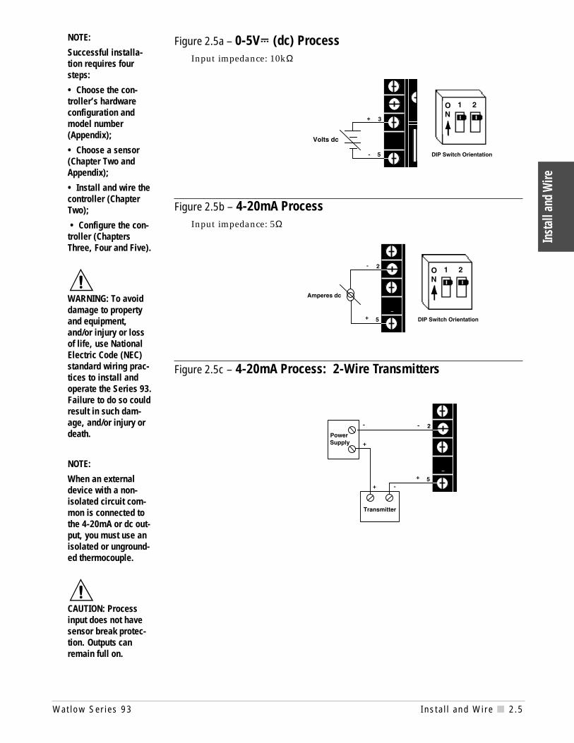
Figure 2.5a – 0-5VÎ (dc) ProcessInput impedance: 10kΩ
Figure 2.5b – 4-20mA ProcessInput impedance: 5Ω
Figure 2.5c – 4-20mA Process: 2-Wire Transmitters
Inst
all a
nd W
ire
NOTE:
Successful installa-tion requires foursteps:
• Choose the con-troller’s hardwareconfiguration andmodel number(Appendix);
• Choose a sensor(Chapter Two andAppendix);
• Install and wire thecontroller (ChapterTwo);
• Configure the con-troller (ChaptersThree, Four and Five).
çWARNING: To avoiddamage to propertyand equipment,and/or injury or lossof life, use NationalElectric Code (NEC)standard wiring prac-tices to install andoperate the Series 93.Failure to do so couldresult in such dam-age, and/or injury ordeath.
NOTE:
When an externaldevice with a non-isolated circuit com-mon is connected tothe 4-20mA or dc out-put, you must use anisolated or unground-ed thermocouple.
çCAUTION: Processinput does not havesensor break protec-tion. Outputs canremain full on.

Output 1 Wiring
Figure 2.6a – Mechanical Relay Without Contact Suppression93_ _- 1 D _ _- 00 _ _
Form C, 5A
Minimum load cur-rent:100mA @ 5VÎ (dc)
Figure 2.6b – Solid-state Relay Without Contact Suppression93_ _- 1 K _ _- 00 _ _
0.5A (ac loads only)
8
10
L2
L1Fuse
ExternalLoad
Customer-suppliedQuencharc
L1
L2
8 NC
9 COM
10 NO
ExternalLoad
Fuse
Customer-suppliedQuencharc
Install and Wire
2.6 Insta l l and Wire Wat low Ser ies 93
NOTE:
Successful installationrequires four steps:
• Choose the controller’shardware configurationand model number(Appendix);
• Choose a sensor(Chapter Two andAppendix);
• Install and wire thecontroller (Chapter Two);
• Configure the con-troller (Chapters Three,Four and Five).
çWARNING: To avoid dam-age to property andequipment, and/or injuryor loss of life, useNational Electric Code(NEC) standard wiringpractices to install andoperate the Series 93.Failure to do so couldresult in such damage,and/or injury or death.
NOTE:
Switching inductive loads(relay coils, solenoids,etc.) with the mechanicalrelay, switched dc orsolid-state relay outputoptions requires use ofan R.C. suppressor.
Watlow carries the R.C.suppressor Quencharcbrand name, which is atrademark of ITWPaktron. Watlow Part No.0804-0147-0000.

Watlow Ser ies 93 Insta l l and Wire 2.7
Figure 2.7a – Switched DC93_ _- 1 C _ _- 00 _ _
Figure 2.7b – 4-20mA Process93_ _- 1 F_ _- 00 _ _
Maximum load impedance: 800Ω
External Load10
9
-
+
External Load10
9
-
+
Inst
all a
nd W
ire
NOTE:
Successful installa-tion requires foursteps:
• Choose the con-troller’s hardwareconfiguration andmodel number(Appendix);
• Choose a sensor(Chapter Two andAppendix);
• Install and wirethe controller(Chapter Two);
• Configure thecontroller (ChaptersThree, Four andFive).
NOTE:
When an externaldevice with a non-isolated circuit com-mon is connected tothe 4-20mA or dcoutput, you must usean isolated or un-grounded thermo-couple.

Output 2 Wiring
Figure 2.8a – Mechanical Relay Without Contact Suppression
93_ _- 1 _ D _ - 00_ _
Form C, 5A
Minimum load current:100mA @ 5VÎ (dc)
Figure 2.8b – Solid-state Relay Without Contact Suppression93_ _- 1_ K _- 00_ _
0.5A (ac loads only)
Figure 2.8c – Switched DC93_ _- 1_ C _ - 00_ _
7
unregulated
V+
V—
6
Internal Circuitry
7 to 10V (dc)94Ω
External Load7
6
-
+
External Load
7
1
FuseL1
L2
Customer-suppliedQuencharc
6 COMNC 1
7 NO
L1
L2
Customer-suppliedQuencharc
ExternalLoad
FuseInstall and Wire
2.8 Insta l l and Wire Wat low Ser ies 93
NOTE:
Successful installationrequires four steps:
• Choose the controller’shardware configurationand model number(Appendix);
• Choose a sensor(Chapter Two andAppendix);
• Install and wire thecontroller (Chapter Two);
• Configure the con-troller (Chapters Three,Four and Five).
NOTE:
Output is in open state inAlarm Condition.
NOTE:
Switching inductive loads(relay coils, solenoids,etc.) with the mechanicalrelay, switched dc orsolid-state relay outputoptions requires use of anR.C. suppressor.
Watlow carries the R.C.suppressor Quencharcbrand name, which is atrademark of ITW Paktron.Watlow Part No. 0804-0147-0000.
çWARNING: To avoid dam-age to property and equip-ment, and/or injury or lossof life, use NationalElectric Code (NEC) stan-dard wiring practices toinstall and operate theSeries 93. Failure to do socould result in such dam-age, and/or injury ordeath.

Watlow Ser ies 93 Insta l l and Wire 2.9
Wiring Example
Figure 2.9 - System Wiring Example.
5 -
DIN-a-miteDA1C-1624-C000
1
Coil
9 (+)
10 (-)
High LimitMechanicalController
Heater
94BB-1DA0-00RRLimit Controller
Limit Sensor
Process Sensor
93BB-1CA0-00RRRear View
5 (-)
3 (+)
11 12
Fuse
Earth Ground
L1
L2120VÅ (ac)
11 12
9
3 +
10
2
3 4
1 (-)
2 (+)
Inst
all a
nd W
ire
ç∫WARNING: To avoiddamage to propertyand equipment,and/or injury or lossof life, use NationalElectric Code (NEC)standard wiringpractices to installand operate theSeries 93. Failure todo so could result insuch damage, and/orinjury or death.
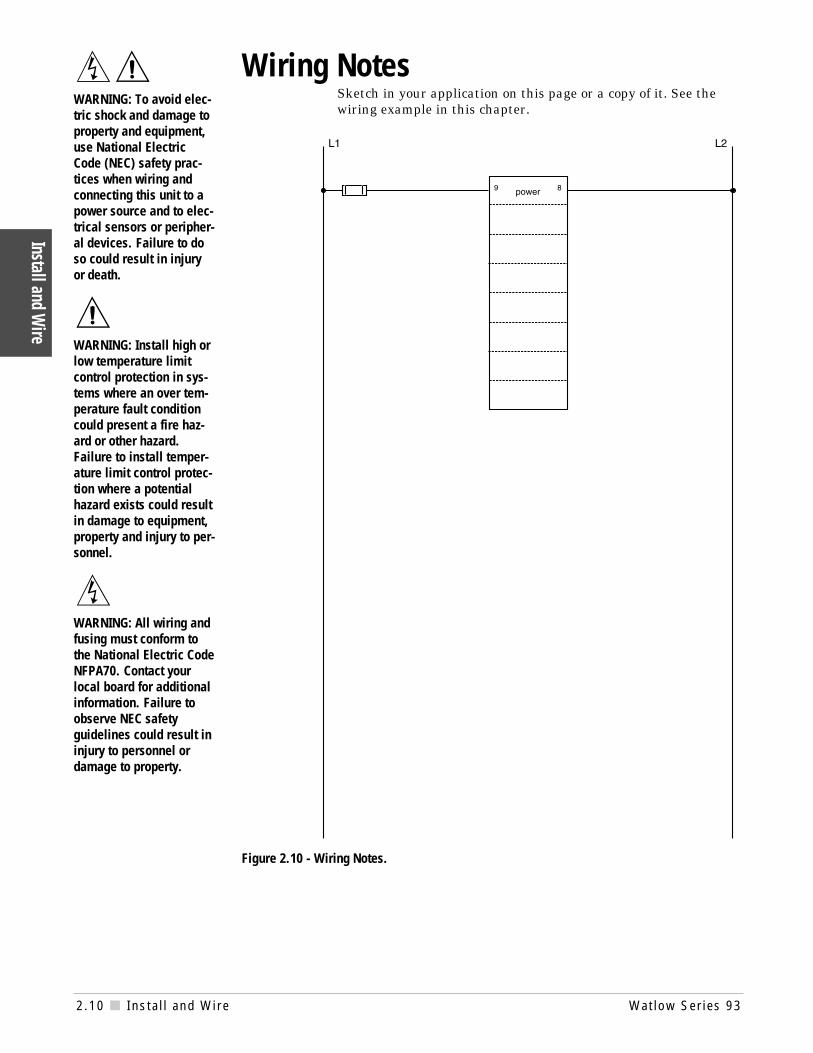
Wiring NotesSketch in your application on this page or a copy of it. See thewiring example in this chapter.
Figure 2.10 - Wiring Notes.
Install and Wire
2.10 Insta l l and Wire Wat low Ser ies 93
∫çWARNING: To avoid elec-tric shock and damage toproperty and equipment,use National ElectricCode (NEC) safety prac-tices when wiring andconnecting this unit to apower source and to elec-trical sensors or peripher-al devices. Failure to doso could result in injuryor death.
çWARNING: Install high orlow temperature limitcontrol protection in sys-tems where an over tem-perature fault conditioncould present a fire haz-ard or other hazard.Failure to install temper-ature limit control protec-tion where a potentialhazard exists could resultin damage to equipment,property and injury to per-sonnel.
∫WARNING: All wiring andfusing must conform tothe National Electric CodeNFPA70. Contact yourlocal board for additionalinformation. Failure toobserve NEC safetyguidelines could result ininjury to personnel ordamage to property.
Watlow Ser ies 93 Keys and Displays 3.1
Keys
and
Dis
play
s
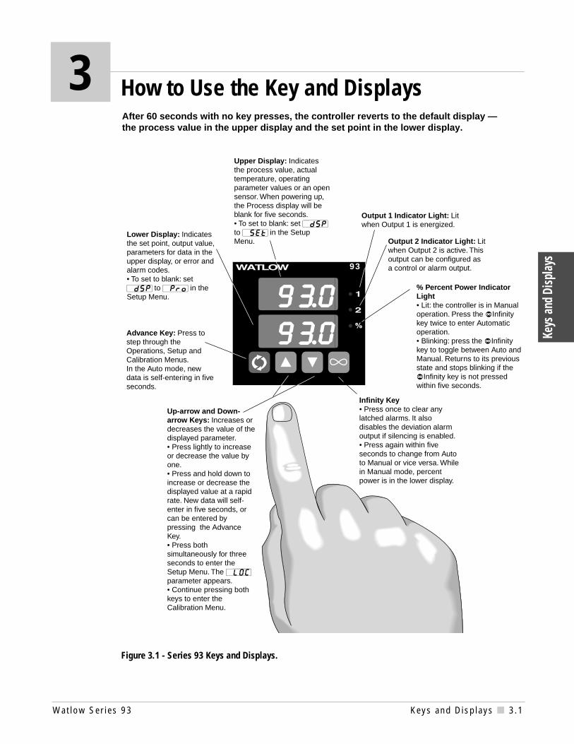
Figure 3.1 - Series 93 Keys and Displays.
After 60 seconds with no key presses, the controller reverts to the default display —the process value in the upper display and the set point in the lower display.
3 How to Use the Key and Displays
Lower Display: Indicates the set point, output value, parameters for data in the upper display, or error and alarm codes. • To set to blank: set [`dSP] to [`Pro] in the Setup Menu.
Infinity Key• Press once to clear any latched alarms. It also disables the deviation alarm output if silencing is enabled.• Press again within five seconds to change from Auto to Manual or vice versa. While in Manual mode, percent power is in the lower display.
% Percent Power Indicator Light• Lit: the controller is in Manual operation. Press the ˆInfinity key twice to enter Automatic operation.• Blinking: press the ˆInfinity key to toggle between Auto and Manual. Returns to its previous state and stops blinking if the ˆInfinity key is not pressed within five seconds.
Output 1 Indicator Light: Lit when Output 1 is energized.
Upper Display: Indicates the process value, actual temperature, operating parameter values or an open sensor. When powering up, the Process display will be blank for five seconds. • To set to blank: set [`dSP] to [`SEt] in the Setup Menu.
Advance Key: Press to step through the Operations, Setup and Calibration Menus. In the Auto mode, new data is self-entering in five seconds.
93
Output 2 Indicator Light: Lit when Output 2 is active. This output can be configured as a control or alarm output.
Up-arrow and Down-arrow Keys: Increases or decreases the value of the displayed parameter.• Press lightly to increase or decrease the value by one. • Press and hold down to increase or decrease the displayed value at a rapid rate. New data will self-enter in five seconds, or can be entered by pressing the Advance Key.• Press both simultaneously for three seconds to enter the Setup Menu. The [`LOC] parameter appears.• Continue pressing both keys to enter the Calibration Menu.

3.2 Keys and Displays Wat low Ser ies 93
Keys and Displays
Notes

Watlow Ser ies 93 Setup 4.1
Setu
p
Figure 4.1a - DIP Switch Location andOrientation.
ON
1 2 ON
1 2 ON
1 2
Controller Chassis -Bottom View
Thermocouple RTD Process
Input Types
Setting up the Series 93 is a simple process. First set the DIP switches tomatch your input type. Refer to the orientation below for the [``In] Inputvalue. Next, configure the Series 93's features to your application in theSetup Menu, then enter values in the Operating Menu. Both tasks use the‰Advance key to move through the menus and the Up-arrow/Down-arrowkeys to select data.
Before entering information in the Setup Menu, set the [`dFL] parameter. If[``SI] is selected, °C, proportional band in % of span, derivative and inte-gral are the defaults. If [``US] is selected, °F, proportional band in degrees,reset and rate are the defaults. Changing the [`dFL] prompt will setparameters to their factory default. Document all current parametersettings first. See the calibration section in the Appendix to change this pa-rameter.
Setting the Input Type DIP SwitchThe Series 93 input type can be user selectable at any time via a Dual In-linePackage (DIP) switch inside the control, located on the left (viewed from thebottom). To set the DIP switch, remove the control chassis from the case.Holding each side of the bezel, press in firmly on the side grips until the tabsrelease. You may need to rock the bezel back and forth several times torelease the chassis.
The locations of the board and switches appear in Figure 4.1. Refer to theinput types below for DIP switch orientation. The DIP switch configurationmust match the sensor selected under the [``In] parameter in the SetupMenu.
∫WARNING:
Remove power from thecontroller before remov-ing the chassis from thecase or changing the DIPswitches. Removing thecontroller from the chas-sis is not a normal oper-ating condition andshould only be done by aqualified technician.
4 How to Set Up the Series 93
Figure 4.1b - Input DIP Switches.

4.2 Setup Wat low Ser ies 93
Setup
[`LOC] Lock[``In] Input[`dEC] Decimal*[`C_F] Celsius - Fahrenheit*[``rL] Range Low[``rH] Range High[`Ot1] Output 1[`HSC] Hysteresis Control[`Ot2] Output 2[`HSA] Hysteresis Alarm*[`LAT] Latching*[`SIL] Silencing*[`rtd] RTD*[`rP`] Ramping[`rT`] Rate*[`P`L] Power Limiting*[`dSP] Display
* Parameter may not always appear.
‰
Setup MenuFigure 4.2b - The Setup Menu.
NOTE:
While in the SetupMenu, all outputs areoff.
The Operation Menu will appear as the default menu of the Series 93. The SetupMenu displays the parameters that configure the Series 93's features to yourapplication.
Enter the Setup Menu by pressing the ¿Up-arrow and ¯Down-arrow keys si-multaneously for 3 seconds. The lower display shows the [`LOC] Lock parame-ter, and the upper display shows its current level. All keys are inactive until yourelease both keys. You can reach the Lock parameter from anywhere.
Use the ‰Advance key to move through the menus and the ¿Up-arrow and¯Down-arrow keys to select data. You will not see all parameters in this menu,depending on the controller's configuration and model number. After steppingthrough the menu it returns to the set point parameter under the OperationMenu. If no keys are pressed for approximately 60 seconds, the controller returnsto the default display, Process over Set Point.
Figure 4.2a - Entering the SetupMenu.
93 93
Entering the Setup Menu
Setu
p
Watlow Ser ies 93 4.3 Setup
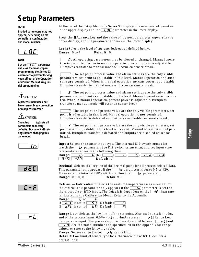
At the top of the Setup Menu the Series 93 displays the user level of operationin the upper display and the [`LOC] parameter in the lower display.
Press the ‰Advance key and the value of the next parameter appears in theupper display, and the parameter appears in the lower display.
Lock: Selects the level of operator lock-out as defined below. Range: 0 to 4 Default: 0
[```0]: All operating parameters may be viewed or changed. Manual opera-tion is permitted. When in manual operation, percent power is adjustable.Bumpless transfer to manual mode will occur on sensor break.
[```1] The set point, process value and alarm settings are the only visibleparameters, set point is adjustable in this level. Manual operation and auto-tune are permitted. When in manual operation, percent power is adjustable.Bumpless transfer to manual mode will occur on sensor break.
[```2] The set point, process value and alarm settings are the only visibleparameters, set point is adjustable in this level. Manual operation is permit-ted. When in manual operation, percent power is adjustable. Bumplesstransfer to manual mode will occur on sensor break.
[```3] The set point and process value are the only visible parameters, setpoint is adjustable in this level. Manual operation is not permitted.Bumpless transfer is defeated and outputs are disabled on sensor break.
[```4] The set point and process value are the only visible parameters, setpoint is not adjustable in this level of lock-out. Manual operation is not per-mitted. Bumpless transfer is defeated and outputs are disabled on sensorbreak.
Input: Selects the sensor input type. The internal DIP switch must alsomatch the `In parameter. See DIP switch orientation, and see input typetemperature ranges in the following chart.Range: [```J], [```H] (K), [```t], [```n], [```S], [`rtd], [`r†d], [`0-5], [`420] Default: J
Decimal: Selects the location of the decimal point for all process-related data.This parameter only appears if the [``In] parameter is set to 0-5 or 420.Make sure the internal DIP switch matches the [``In] parameter. Range: 0, 0.0, 0.00 Default: 0
Celsius — Fahrenheit: Selects the units of temperature measurement forthe control. This parameter only appears if the [``In] parameter is set to athermocouple or RTD input. The default is dependent on the [`dFL] parame-ter located in the Calibration Menu. Refer to the Appendix.Range: [```C] or [```F]If [`dFL] is set to [``SI]: Default: [```C]If [`dFL] is set to [``US]: Default: [```F]
Range Low: Selects the low limit of the set point. Also used to scale the lowend of the process input. 0.0VÎ (dc) and 4mA represent [``rL] Range Lowfor a process input. The process input is linearly scaled between [``rL] and[``rH]. See the model number and specification in the Appendix for rangevalues, or refer to the following table.Range: Sensor range low to [``rh] Range HighDefault: Low limit of sensor type for a thermocouple or RTD. -500 for aprocess input.
``In
`dEC
`C-F
çCAUTION:
A process input does nothave sensor break protectionor bumpless transfer.
NOTE:
Shaded parameters may notappear, depending on thecontroller’s configurationand model number.
çCAUTION:
Changing [``In] sets allparameters to factorydefaults. Document all set-tings before changing thisparameter.
NOTE:
Set the [`LOC] parametervalue as the final step inprogramming the Series 93controller to prevent lockingyourself out of the Operationand Setup Menu during ini-tial programming.
[`LOC
Setup Parameters
``rL

4.4 Setup Wat low Ser ies 93
Setup
Range High: Selects the high limit of the operating range. Also used to scale thehigh end of the process input. 5.0VÎ (dc) and 20mA represent Range High [``rh] fora process input. The process input is linearly scaled between [``rL] and [``rH]. Seethe model number and specification information in the Appendix for your range val-ues, or refer to the following table.Range: Sensor range high to [``rL]Default: High limit of sensor type for a thermocouple or RTD. 9999 for process input.
Output 1: Selects the action for the primary output in response to the differencebetween set point and process variable. Select [``ht] (heat) for reverse acting orselect [``CL] (cool) for direct acting.Range: [``ht], [``CL] Default: [``ht]
Hysteresis-Control: Selects the switching hysteresis for Output 1 and 2 when youselect 0 (on-off) under the [`Pb1] parameter and [`Ot2] is set to [`Con].Range: 1 to 55, 0.1 to 5.5, 0.01 to 0.55°C/1 to 99, 0.1 to 9.9, 0.01 to 0.99°FDefault: 2, 0.2, 0.02°C/3, 0.3, 0.03°F
Output 2: Selects the output action for the secondary output.Range: [`Con] Control mode opposite Output 1 (heat or cool)
[`PrA] Process alarm with alarm message displayed[``Pr] Process alarm with no alarm message displayed[`dEA] Deviation alarm with alarm message displayed[``dE] Deviation alarm with no alarm message displayed[``no] None
Default: [`Con]
Hysteresis - Alarm: Selects the switching hysteresis for Output 2 when [`Ot2] isan alarm. Appears only if [`Ot2] is not set to [`Con] or [``no]. See the OperationMenu for [`Pb1].Range: 1 to 5555, 0.1 to 555.5, 0.01 to 55.5°C/1 to 9999, 0.1 to 999.9, 0.01 to 99.99°FDefault: 2, 0.2, 0.02°C/3, 0.3, 0.03°F
Latching: Selects whether the alarm is latching or non-latching. Latching alarmsmust be cleared by pressing the ˆInfinity key before the alarm output will reset.Selecting non-latching will automatically reset the alarm output when the conditionclears. Appears only if [`Ot2] is not set to [`Con] or [``no]. Range: [`LAt] or [`nLA] Default: [`nLA]
Silencing: Selects alarm silencing (inhibit) for the alarm. Appears only when [`Ot2]
is set to [`dEA] or [``dE]. For more information see Chapter 5.Range: [``On] or [`OFF] Default: [`OFF]
RTD: Selects the RTD calibration curve for RTD inputs. Will not appear unless[``In] is set to [`rtd] or [`r†d]. [`JIS] is 0.003916Ω/Ω°C, [`Din] is0.003850Ω/Ω°C.Range: [`din] or [`JIS] Default: [`din]
Ramping: Choose [`Str], and the set point ramps at the selected rate in °/hr. fromthe process (actual) temperature to the set point, when power is applied to the con-troller (start up). It will not ramp with a set point change. [`On] is the same as[`Str], but ramps with a set point change. It ramps from the previous set point to anew one at the selected ramp rate. Select [`OFF] for no ramping action. When ramp-ing, the lower display alternately flashes [``rP]. The set point displayed is thedesired end set point. The ramping set point is not shown. Entering the Setup Menuor manual operation disables the outputs and ramp. Once you exit either one, theSeries 93 controls to the last entered set point.Range: [`Str], [``On], [`OFF] Default: [`OFF]
Rate: Selects the ramping rate in degrees per hour. Will not appear if [``rP] is setto [`OFF].Range: 0 to 9999 Default: 100°/hr.
`HSC
`Ot1
`Ot2
`HSA
``rh
`LAt
`SIL
`rtd
``rt
`rP`

Watlow Ser ies 93 Setup 4.5
Setu
p
Parameter Value Range Factory Default Appears If:[`LOC] 0 to 4 0
[``In] [```J], [```H], [```t], [```n], [```S], [```J] DIP switch selectable.[`rtd], [`r†d], [`0-5], [`420]
[`dEC] 0, 0.0, 0.00 0 [``In] is set to [`0-5] or [`420]
[`C_F] [```C] or [```F] Dependent on [`dFL] [``In] is set to [```J], [```H],[```t],[```n],[```S], [`rtd], or [`r†d]
[``rL] [``rL] to [``rh] Input dependent
[``rh] ``rh] to [``rL] Input dependent
[`Ot1] [``ht] or [``CL] [``ht]
[`HSC] 1 to 55, 0.1 to 5.5, 0.01 to 0.55°C 2, 0.2, 0.02°C1 to 99, 0.1 to 9.9, 0.01 to 0.99°F 3, 0.3, 0.03°F
[`Ot2] [`Con] Control [`Con][`PrA] Process alarm[``Pr] Process with no alarm message[`dEA] Deviation alarm[``dE] Deviation with no alarm message[``no] None
[`HSA] 1 to 5555, 0.1 to 555.5, 0.01 to 55.55°C 2, 0.2, 0.02°C [`Ot2] is not set to [`Con] or [``no]
1 to 9999, 0.1 to 999.9, 0.01 to 99.99°F 3, 0.3, 0.03°F
[`LAt] [`LAt] or [`nLA] [`nLA] [`Ot2] is not set to [`Con] or [``no]
[`SIL] [``On] or [`OFF] [`OFF] [`Ot2] is set to [`dEA] or [``dE]
[`rtd] [`JIS] or [`din] [`din] [``In] is set to [`rtd] or [`r†d]
[`rP`] [`Str] Ramping on power up [`OFF]
[``On] Ramping to set point at all times[`OFF] None
[`rt`] 0 to 9999 100°/hr [``rP] is not set to [`OFF]
[`P`L] 0 to 100 100 [`Ot1] or [`Ot2] is set to [``ht]
[`dsP] [`nor] normal [`nor]
[`SEt] Set Point (lower only)[`Pro] Process (upper only)
Input Type Sensor Range Low Sensor Range High
[```J] 0°C/32°F 750°C/1382°F[```H] -200°C/-328°F 1250°C/2282°F[```t] -200°C/-328°F 350°C/662°F[```n] 0°C/32°F 1250°C/2282°F[```S] 0°C/32°F 1450°C/2642°F[`rtd] (1°) -200°C/-328°F 700°C/1292°F[`r†d] (0.1°) -128.8°C/-199.9°F 537.7°C/999.9°F[`420] 4mA/-999 units 20mA/9999 units
[`0-5] 0VÎ (dc)/-999 units 5VÎ (dc)/9999 units
Table 4.5a - Input Ranges.
`dSP
Table 4.5b - Setup Menu Prompts andDescriptions.
Setup Menu
Power Limiting: The power limiting function in % power for heat only. PowerLimiting will function if [`pb1] is set to [```0].Range: Dependent on output type. 0 to100 Default: 100
Display: Selects which displays are active or viewable. Five seconds after select-ed, the appropriate display goes blank. Press ‰Advance, ¿Up-arrow or ¯Down-arrow to override this feature and cause the current value to be displayed for 5seconds. Range: [`nor]Normal displays Default: [`nor]
[`SEt] Set Point - lower display only[`Pro] Process - upper display only
NOTE:
Document your SetupMenu parameters.Do not mark any valueshere; make photocopiesinstead.
[`P`L]

4.6 Setup Wat low Ser ies 93
Setup
NOTE:
Shaded parametersmay not appear,depending on thecontroller’s configu-ration and modelnumber.
Operation Parameters
Set Point: Sets the operating set point for Output 1. Represents the process valuethe system tries to achieve for Output 1. "SP" does not appear on the lower display.The control set point value is displayed and can be incremented or decrementedwithout pressing the ‰Advance key. The lower display may be blank if [`dSP] is setto [`Pro]. In a ramping mode, the lower display alternately flashes the desired endset point and [``rP].
Proportional Band 1 and 2: A proportional band, expressed in degrees or % ofspan, within which a proportioning function is active for Output 1 or 2. When[`Pb1] is set to 0, the unit functions as an on-off control on Output 1 and 2.[`Pb2] will not appear if [`Pb1] is set to 0 or [`Ot2] is not set to [`Con]. Theswitching differential is determined by the [`HSC] parameter.Range if [`dFL] is set to [``US]: [`Pb1]: 0 to 555°C/0 to 999°F/0 to 999 Units; 0.0to 5.5°C/0.0 to 9.9°F/0.0 to 9.9 units, [`Pb2]: The same as [`Pb1] except lowerlimit is 1 or 0.1. Defaults: [`Pb1] is set to 2.5°C/25°F [`Pb2] is set to 25Range if [`dFL] is set to [``SI]: 0 to 999.9% of spanDefaults: [`Pb1] is set to 3.0% [`Pb2] is set to 3.0%
Reset /Integral 1 and 2: An integral control action for Output 1 or 2 that auto-matically eliminates offset, or "droop," between set point and actual process tem-perature. [`rE1]/[`It1]: Will not appear if [`Pb1] is set to 0. [`rE2]/[`It2]:Appears if [`Pb1] is not set to 0 and [`Ot2] is set to [`Con]. Either reset [``rE]or integral [``It] will appear depending on how the [`dFL] parameter is set inthe Calibration Menu. See the Appendix.Range if [`dFL] is set to [``US]: 0 to 9.99 repeats/minute Default: 0.00Range if [`dFL] is set to [``SI]: 00.1 to 9.99 minutes per repeat Default: 0.00
Rate/Derivative 1 and 2: The rate (derivative) function for Output 1 or Output2.Eliminates overshoot on startup, or after the set point changes. [`rA1]/[`dE1]:Will not appear if [`Pb1] is set to 0. [`rA2]/[`dE2]: Appears if [`Pb1] is not setto 0 and [`Ot2] is set to [`Con]. Either rate [``rA] or derivative [``dE] appearsdepending on how [`dFL] is set in the Calibration Menu.Range if [`dFL] is set to [``US] or [``SI]: 0 to 9.99 minutes Default: 0.0
Cycle Time 1 and 2: Time for a controller to complete one time-proportioned cyclefor Output 1 or Output 2; expressed in seconds. [`Ct1]: Will not appear if [`Pb1]is set to 0, or Output 1 is 4-20mA. [`Ct2]: Will not appear if [`Pb1] is set to 0 or[`Ot2] is not set to [`Con].
[``SP
NOTE:
The upper displaywill always return tothe process valueafter 1 minute with-out key strokes.
`rE1
`It1
`rE2
`It2
`Ct1`Ct2
`rA1
`dE1
`rA2
`dE2
`Pb1`Pb2
[``93] Control Set Point[`Pb1] Proportional Band 1[`rE1] Reset 1*[`It1] Integral 1*[`rA1] Rate 1*[`dE1] Derivative 1*[`Ct1] Cycle Time 1*[`ALO] Alarm Low*[`AHI] Alarm High*[`Pb2] Proportional Band 2*[`rE2] Reset 2*[`It2] Integral 2*[`rA2] Rate 2*[`dE2] Derivative 2*[`Ct2] Cycle Time 2*[`CAL] Calibration Offset[`AUt] Autotune
‰
Operation Menu
* Parameter may not always appear.
Operation MenuFigure 4.6 - The Operation Menu.

Watlow Ser ies 93 Setup 4.7
Setu
p
Operation Parameters Value Range Factory Default[`Pb1] If [`dFL] is set to [``US]:
0 to 555°C/0 to 999°F/0 to 999 Units 2.5°C0 to 55.5°C/0 to 99.9°F/0 to 99.9 Units 25°F0 is control. [`HSC] is set to switch differential
If [`dFL] is set to [``SI]:0.0 to 999.9% of span 3%
[`rE1] 0.00 to 9.99 repeats/minute 0.00 repeats/minute0.00 = No Reset. Won't appear if [`Pb1] is set to 0or [`dFL] is set to [``SI].
[`It1] 0.0 to 99.9 minutes/repeat. 0.00 = No Integral. 00.0 minutes/repeatWon't appear if [`Pb1] is set to 0 or [`dFL] is set to [``US].
[`rA1] 0.00 to 9.99 minutes 0.00 minutes0.00 = No Rate. Will not appear if [`Pb1] is set to 0or [`dFL] is set to [``SI].
[`dE1] 0.00 to 9.99 minutes. 0.00 = No Derivative. 0.00 minutesWon't appear if [`Pb1] is set to 0 or [`dFL] is set to [``US].
[`Ct1] 0.1 to 999.9 5.0 secondsWon't appear if [`Pb1] is set to 0, or [`420].
[`Pb2] Same as [`Pb1]. [`Pb2] lower limit = 1, 0.1, 0.01
[`rE2] Same range as [`rE1].
[`It2] Same range as [`It1].
[`rA2] Same range as [`rA1].
[`dE2] Same range as [`dE1].
[`Ct2] Same range as [`Ct1].
[`ALO] Deviation [``dE] -999 to 0 -999Process [``Pr] [``rL] to [`AHI] [``rL]
Will not appear if [`Ot2] is set to [``no] or [`Con].
[`AHI] Deviation [``dE] 0 to 999 999Process [``Pr] [`ALO] to [``rH] [``rH]
Will not appear if [`Ot2] is set to [``no] or [`Con].
[`CAL] ±100°C/±180°F/±180 Units 0
[`AUt] 0 to 3 0
If a mechanical relay or contactor is switching power to the load, a longercycle time may be desirable to minimize wear on the mechanical compo-nents. Typical life of a mechanical relay is 100,000 cycles.Range: 0.1 to 999.9 seconds Default: 5.0 seconds
Alarm Low: Represents the low process alarm or low deviation alarm. This para-meter will not appear if [`Ot2] is set to no or [`Con]. Range if [`Ot2] is set to [`dEA] or [``dE]: -999 to 0 Default: -999Range if [`Ot2] is set to [`PrA] or [``Pr]: [``rL] to [`AHI] Default: [``rL]
Alarm High: Represents the high process alarm or high deviation alarm. Thisparameter will not appear if [`Ot2] is set to [``no] or [`Con]. Range if [`Ot2] is set to [`dEA] or [``dE]: 0 to 999 Default: 999Range if [`Ot2] is set to [`PrA] or [``Pr]: [`ALO] to [``rH] Default: [``rH]
Calibration Offset: Adds or subtracts degrees from the input signal.Range: -100°C to 100°C/-180°F to 180°F/-180 units to 180 units; or-10.0°C to 10.0°C/-18.0°F to 18.0°F Default: 0
Autotune: Initiates an autotune.Range: 0 is set to off, 1 is set to slow, 2 is set to medium, 3 is set to fastDefault: 0
Table 4.7 - Operation MenuPrompts andDescriptions.
`ALO
Operation MenuDocument your Series 93 Operation Parameters.Do not mark any values here; make photocopies instead.
`AHI
`AUt
`CAL

4.8 Setup Wat low Ser ies 93
Setup
Notes

Watlow Ser ies 93 Tuning and Operat ing 5.1
Tunin
g and
Ope
ratin
g
Autotuning (Heat and/or Cool)
The Series 93 can automatically tune the PID parameters to fit the characteristicsof your particular thermal system.
The autotuning procedure operates on a thermal response value — slow, medium,or fast. Use the slow thermal response when your process does not need to reach theset point too rapidly, or if it usually does not often exceed the set point. A fast ther-mal response produces a rapid temperature change over a short period of time.
Once the autotune sequence has begun, the Output 1 heat proportional band is setto 0 and the control goes into an on-off mode of control at 90% of the established setpoint. The displayed set point remains unchanged.
Once the controller finishes "learning" the system, it returns to a standard PID con-trol with the PID values automatically set as a result of autotuning. Autotune doesnot change cycle time parameters. The controller can also be manually tuned. Seethe next page for instructions on how to manually tune the controller. Any changeof the set point, while in autotune, re-initiates the autotune procedure.
NOTE:
Set the [`HSC]
parameter under theSetup Menu to2°C/3°F before auto-tuning your con-troller.
Figure 5.1 -
Autotuning at a SetPoint of 200°F.
In order for the Series 93 to successfully complete the autotune, the process mustcross 90% of the set point four times within 80 minutes after the autotune hasstarted. If this does not happen within the 80-minute time limit, the [``Pb]remains at 0 and the controller functions in an on-off mode.
To start autotuning:
1. Press the ‰Advance key until the [`AUt] prompt appears in the data display.
2. Select a thermal response value using the ¿Up-arrow/¯Down-arrowkeys: 1 for a slow response, 2 for an average response and 3 for a system thatresponds quickly. A thermal response value of 2 satisfactorily tunes most thermalsystems.
3. Press the ‰Advance key. While the controller is in the tuning mode, the lowerdisplay alternately displays the normal information and the prompt [`AUt], at one-second intervals.
200
°Tem
per
atu
re
Set Point
100
Process
180
AutotuneBegins
AutotuneComplete
90% of Set Point
Time
5 How to Tune and Operate the Series 93

5.2 Tuning and Operat ing Wat low Ser ies 93
Tuning and Operating
4. When tuning is complete, the displays return to their previous state and[`AUt] reverts to 0. The Series 93 installs appropriate PID tuning parametersand saves them in the non-volatile memory. If a mechanical relay or contac-tor is switching power to the load, a longer cycle time may be desirableto minimize wear on the mechanical components. Typical life of a me-chanical relay is 100,000 cycles.
To abort autotuning either reset the [`AUt] parameter to 0, press theˆInfinity key twice, or cycle power off and on. In all cases, aborting autotunerestores all values to those previous to autotuning.
Manual TuningFor optimum controller performance, tune the Series 93 to your thermal sys-tem. The tuning settings here are for a broad spectrum of applications; yoursystem may have somewhat different requirements. NOTE: This is a slowprocedure, taking from minutes to hours to obtain optimum value.
1. Apply power to the Series 93 and enter a set point. Set Operation parame-ters as follows: [``Pb] to [```1], [``rE] / [``It] to [`)00], [``rA] /[``dE] to [`)00], [``Ct] to [``%0], [`CAL] to [```0], [`AUt] to [```0].
2. Proportional Band Adjustment: Gradually increase [``Pb] until theupper display temperature stabilizes to a constant value. The process tem-perature will not be right on set point because the initial reset value is 0.00repeats per minute. (When [``Pb] is set to 0; [``rE] / [``It] and [``rA] /[``dE] are inoperative, and the Series 93 functions as a simple on-off con-troller.) The [`HSC] parameter determines the switching differential value.
3. Reset/Integral Adjustment: Gradually increase [``rE], or decrease[``It] until the upper display temperature begins to oscillate or "hunt."Then slowly decrease [``rE] or increase [``It] until the upper display sta-bilizes again near the set point.
4. Cycle Time Adjustment: Set [``Ct] as required. Faster cycle timessometimes achieve the best system control. However, if a mechanical contac-tor or solenoid is switching power to the load, a longer cycle time may be de-sirable to minimize wear on the mechanical components. Experiment untilthe cycle time is consistent with the quality of control you want. [``Ct] willnot appear on units with a process output.
5. Rate/Derivative Adjustment: Increase [``rA] / [``dE] to 1.00 minute.Then raise the set point by 11° to 17°C, or 20° to 30°F. Observe the system'sapproach to the set point. If the load temperature overshoots the set point, in-crease [``rA] / [``dE] to 2.00 minutes.
Raise the set point by 11 to 17°C, or 20 to 30°F and watch the approach to thenew set point. If you increase [``rA] / [``dE] too much, the approach to theset point is very sluggish. Repeat as necessary until the system rises to thenew set point without overshooting or approaching the set point too slowly.
6. Calibration Offset Adjustment: You may want your system to control toa temperature other than the value coming from the input sensor. If so,measure the difference between that temperature (perhaps at another pointin the system) and the process value showing in the upper display. Thenenter the calibration offset value you want. Calibration offset adds or sub-tracts degrees from the value of the input signal.
NOTE:
Tune heating outputs at aset point above ambienttemperature.
Tune cooling outputs at aset point below ambienttemperature.

Watlow Ser ies 93 Tuning and Operat ing 5.3
Tunin
g and
Ope
ratin
g
Manual and Automatic OperationTo change from auto to manual operation, press the ˆInfinity key twice.
Manual operation provides open loop control of the outputs from a range of -100%(full cooling) to 100% (full heating) power. The Series 93 allows a negative outputvalue only when [`Ot2] is set to [`Con]. Automatic operation provides closed-loop on-off or PID control. When the operator transfers from a closed-loop to anopen loop, the Series 93 retains the power level from the closed-loop control,referred to as bumpless transfer. When the Series 93 returns to closed-loop con-trol, it restores the previous set point temperature.
The percent indicator light indicates auto or manual operation. When the percentindicator light is on, the control is in manual operation and displays the percentpower value in the lower display. When the percent indicator light is off, it is inautomatic operation. Press the ˆInfinity key to flash the percent indicator light.Press the ˆInfinity key again to complete the manual/automatic change.
When a sensor opens, the Series 93 switches from automatic to manual operationif [`LOC] is set to 0, 1 or 2.
•If [`LOC] is set to 0, 1 or 2 and the bumpless transfer conditions are met, theSeries 93 switches to manual operation at the last automatic power level. Thebumpless transfer conditions are: the process has stabilized within a ± 5%power level for at least two minutes prior to sensor break provided the powerlevel is less than 75%.
•If [`LOC] is set to 3 or 4, the Series 93 switches into manual operation at 0%power (outputs disabled).
When transferring from auto to manual operation, the controller output(s)remains stable ("bumpless," smooth transition). When transferring from manualto automatic operation, the controller output(s) may change significantly. Inmanual operation, the output value appears in the lower display; in automaticoperation, the set point appears.
NOTE:
A process input doesnot have sensor breakprotection or bump-less transfer. Outputsselected as [``ht]
(reverse acting) willbe full on if a sensorbreak occurs.
5.4 Tuning and Operat ing Wat low Ser ies 93
Tuning and Operating
NOTE:
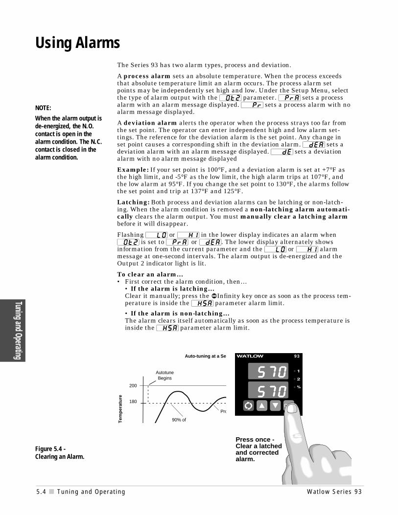
When the alarm output isde-energized, the N.O.contact is open in thealarm condition. The N.C.contact is closed in thealarm condition.
Press once -Clear a latchedand correctedalarm.
The Series 93 has two alarm types, process and deviation.
A process alarm sets an absolute temperature. When the process exceedsthat absolute temperature limit an alarm occurs. The process alarm setpoints may be independently set high and low. Under the Setup Menu, selectthe type of alarm output with the [`Ot2] parameter. [`PrA] sets a processalarm with an alarm message displayed. [``Pr] sets a process alarm with noalarm message displayed.
A deviation alarm alerts the operator when the process strays too far fromthe set point. The operator can enter independent high and low alarm set-tings. The reference for the deviation alarm is the set point. Any change inset point causes a corresponding shift in the deviation alarm. [`dEA] sets adeviation alarm with an alarm message displayed. [``dE] sets a deviationalarm with no alarm message displayed
Example: If your set point is 100°F, and a deviation alarm is set at +7°F asthe high limit, and -5°F as the low limit, the high alarm trips at 107°F, andthe low alarm at 95°F. If you change the set point to 130°F, the alarms followthe set point and trip at 137°F and 125°F.
Latching: Both process and deviation alarms can be latching or non-latch-ing. When the alarm condition is removed a non-latching alarm automati-cally clears the alarm output. You must manually clear a latching alarmbefore it will disappear.
Flashing [``LO] or [``HI] in the lower display indicates an alarm when[`Ot2] is set to [`PrA] or [`dEA]. The lower display alternately showsinformation from the current parameter and the [``LO] or [``HI] alarmmessage at one-second intervals. The alarm output is de-energized and theOutput 2 indicator light is lit.
To clear an alarm…• First correct the alarm condition, then…
• If the alarm is latching…Clear it manually; press the ˆInfinity key once as soon as the process tem-perature is inside the [`HSA] parameter alarm limit.
• If the alarm is non-latching…The alarm clears itself automatically as soon as the process temperature isinside the [`HSA] parameter alarm limit.
Figure 5.4 - Clearing an Alarm.
200
Tem
per
atu
re
Pro
180
AutotuneBegins
90% of
Auto-tuning at a Se 93
Using Alarms

Watlow Ser ies 93 Tuning and Operat ing 5.5
Tunin
g and
Ope
ratin
g
Four dashes [----] in the upper display indicate a Series 93 error. The errorcode is visible in the lower display.
[`Er2] - Sensor underrange error (applies only to RTD units)The sensor input generated a value lower than the allowable signal range, orthe analog-to-digital circuitry malfunctioned. Enter a valid input. Make surethe [``In] parameter (Setup Menu) and the DIP switch settings both matchyour sensor.
[`Er4] - Configuration errorThe controller’s microprocessor is faulty; call the factory.
[`Er5] - Nonvolatile checksum errorThe nonvolatile memory checksum discovered a checksum error. Unless amomentary power interruption occurred while the controller was storingdata, the nonvolatile memory is bad. Call the factory.
[`Er6] - Analog-to-digital underflow errorThe analog-to-digital circuit is underrange. An open or reversed polarity sen-sor is the most likely cause. Check the sensor; if the connection is good andfunctions properly, call the factory. The analog-to-digital underrange voltageis too low to convert an analog-to-digital signal. Make sure the [``In] para-meter (Setup Menu) matches your sensor and the DIP switches are setaccordingly.
[`Er7] - Analog-to-digital overflow errorThe analog-to-digital circuit is overrange. An open or reversed polarity sensoris the most likely cause. Check the sensor; if the connection is good, and thesensor functions properly, call the factory. The analog-to-digital overrangevoltage is too high to convert an analog-to-digital signal. Make sure the[``In] parameter (Setup Menu) matches your sensor and the DIP switchesare set accordingly.
Alarm Silencing is available with the deviation alarm and has two uses:
When [`SIL] is selected as "on," the operator must manually disable the alarmby pressing the ˆInfinity key once on initial power up (in either the latching ornon-latching mode). Alarm silencing disables the alarm output relay. However,the Output 2 indicator light (also the lower display when [`Ot2] is set to [`dEA])shows an alarm condition until the process value is within the “safe” region of thedeviation alarm band. Once the process value crosses into the “safe” region, botha latching or a non-latching alarm is ready. Any future deviation outside this safeband triggers an alarm.
NOTE:
An alarm display willbe masked by anerror condition orwhen the controller isin the Calibration orSetup Menus.
çCAUTION:
Electrical noise or anoise event, vibrationor excess environ-mental moisture ortemperature maycause Series 93errors to occur. If thecause of an error isnot otherwise appar-ent, check for these.
93
Error Code Messages
Figure 5.5 -
Error Code Message.
5.6 Tuning and Operat ing Wat low Ser ies 93
Tuning and Operating
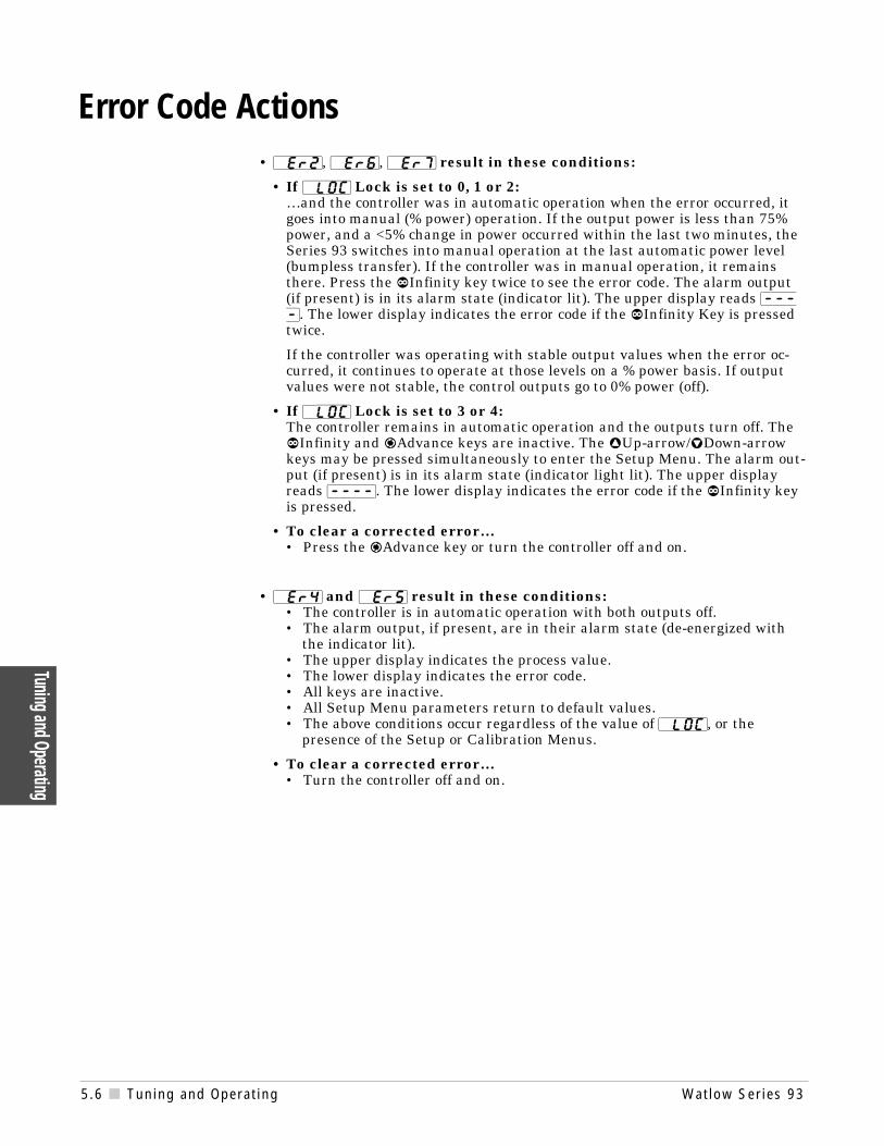
• [`Er2], [`Er6], [`Er7] result in these conditions:
• If [`LOC] Lock is set to 0, 1 or 2:…and the controller was in automatic operation when the error occurred, itgoes into manual (% power) operation. If the output power is less than 75%power, and a <5% change in power occurred within the last two minutes, theSeries 93 switches into manual operation at the last automatic power level(bumpless transfer). If the controller was in manual operation, it remainsthere. Press the ˆInfinity key twice to see the error code. The alarm output(if present) is in its alarm state (indicator lit). The upper display reads [----]. The lower display indicates the error code if the ˆInfinity Key is pressedtwice.
If the controller was operating with stable output values when the error oc-curred, it continues to operate at those levels on a % power basis. If outputvalues were not stable, the control outputs go to 0% power (off).
• If [`LOC] Lock is set to 3 or 4:The controller remains in automatic operation and the outputs turn off. TheˆInfinity and ‰Advance keys are inactive. The ¿Up-arrow/¯Down-arrowkeys may be pressed simultaneously to enter the Setup Menu. The alarm out-put (if present) is in its alarm state (indicator light lit). The upper displayreads [----]. The lower display indicates the error code if the ˆInfinity keyis pressed.
• To clear a corrected error…• Press the ‰Advance key or turn the controller off and on.
• [`Er4] and [`Er5] result in these conditions:• The controller is in automatic operation with both outputs off.• The alarm output, if present, are in their alarm state (de-energized with
the indicator lit).• The upper display indicates the process value.• The lower display indicates the error code.• All keys are inactive.• All Setup Menu parameters return to default values.• The above conditions occur regardless of the value of [`LOC], or the
presence of the Setup or Calibration Menus.
• To clear a corrected error…• Turn the controller off and on.
Error Code Actions

Watlow Ser ies 93 Appendix A.1
Appe
ndix
Noise and Installation Guidelines
For wiring guidelines, refer to the IEEE Standard No. 518-1982, availablefrom IEEE, Inc. 345 East 47th Street, New York, NY 10017.
Noise Sources• Switches and relay contacts operating inductive loads such as motors,
coils, solenoids, and relays, etc.
• Thyristors or other semiconductor devices which are not zero crossover-fired (randomly-fired or phase angle-fired devices).
• All welding machinery and heavy current carrying conductors.
• Fluorescent and neon lights.
Decreasing Noise Sensitivity• Physical separation and wire routing must be given careful consideration
in planning the system layout. For example, ac power supply lines shouldbe bundled together and physically kept separate from input signal lines(sensor lines). A 305-mm (12-inch) minimum separation is usually effec-tive. Keep all switched output signal lines (high power level) separate frominput signal lines (sensor lines). Cross other wiring at 90° angles whenev-er crossing lines is unavoidable.
• Look at the system layout; identify and locate electrical noise sources suchas solenoids, relay contacts, motors, etc. Route the wire bundles and cablesas far away as possible from these noise sources. Don't mount relays orswitching devices close to a microprocessor controller. Don't have phaseangle-fired devices in the same electrical enclosure or on the same powerline with the controller.
• Shielded cables should be used for all low power signal lines to protectthem from magnetic and electrostatic coupling of noise. Some simplepointers are:◊ Whenever possible, run low-level signal lines unbroken from signal
source to the controller circuit.◊ Connect the shield to the controller circuit common at the controller end
only. Never leave the shield unconnected at both ends. Never connectboth shield ends to a common or ground.
◊ Maintain shield continuity at daisy chain connection points by recon-necting the broken shield.
◊ Assume no electrostatic shielding when using the shield as a signalreturn. If you must do this, use triaxial cable (electrostatically shieldedcoaxial cable).
A Appendix

A.2 Appendix Wat low Ser ies 93
Appendix
• Use twisted pair wire any time controller circuit signals must travel morethan two feet, or when you bundle them in parallel with other wires.
• Select the size or gauge of wire by calculating the maximum circuit currentand choosing the gauge meeting that requirement. Using greatly largerwire sizes than required generally increases the likelihood of electrostatic(capacitance) coupling of noise.
• Eliminate ground loops in the entire controller system. You can spot theobvious loops by studying the "as-built" wiring diagram. There are alsonot-so-obvious ground loops resulting from connecting internal circuit com-mons in the manufacturer's equipment.
• Do not daisy chain ac power (or return) lines, or output signal (or return)lines to multiple controller circuits. Use a direct line from the power sourceto each input requiring ac power. Avoid paralleling L1 (power lead) and L2(return lead) to load power solenoids, contactors, and controller circuits. Ifan application uses L1 (power lead) to switch a load, L2 (return lead) hasthe same switched signal and could couple unwanted noise into a con-troller circuit.
• Tie all ground terminals together with one lead (usually green wire) tied toground at one point. Don't connect the ground to the controller case if thecontroller is in a grounded enclosure (preventing ground loops).
• Do not confuse chassis grounds (safety ground) with controller circuit com-mons or with ac supply L2 (return or neutral line). Each return systemwiring must be separate. Absolutely never use chassis ground (safety) as aconductor to return circuit current.
Eliminating Noise• Use "snubbers" (QUENCHARC™ P/N: 0804-0147-0000) to filter out noise
generated by relays, relay contacts, solenoids, motors, etc. A snubber is asimple filter device using a 0.1µf, 600 volt, non-polarized capacitor inseries with a 100Ω, 1/2 watt resistor. The device can be used on ac or dccircuits to effectively dampen noise at its source. Refer to output wiring inChapter Two for proper Quencharc installation.
• The ultimate protection is an "uninterruptable" power supply. This "sens-es" the ac power line; when the line fluctuates, a battery-powered 60Hz inverted circuit takes over, supplying power within one-half to one cycle of the ac line.

Watlow Ser ies 93 Appendix A.3
Appe
ndix
Figure A.3 - Entering the Calibration Menu.
NOTE:While in the Calibra-tion Menu, the con-troller output(s) gooff and the alarmoutput (if present) ison.
NOTE:Calibration valueswill not be retainedunless you are in theMANUAL mode. Donot enter the MAN-UAL mode until youare at the correctinput parameters.
CalibrationBefore attempting to calibrate, make sure you read throughthe procedures carefully and have the proper equipmentcalled for in each procedure. Make sure the DIP switchesare in the proper position for the input type. See ChapterFour.
Entering the Calibration MenuIn the Calibration Menu, various input signals must be supplied for the con-troller to go through its auto calibration. The Calibration Menu can only beentered from the [`LOC] Lock parameter in the Setup Menu. Press the ¿Up-arrow/¯Down-arrow keys simultaneously for 3 seconds (± 1 second). The [`CAL]parameter appears in the lower display with "no" in the upper display.
Any inadvertent change in the displayed data, when pressing the ¿Up-arrow/¯Down-arrow keys, is ignored. Calibration values won't be retained unlessyou are in the manual mode. Press the ¿Up-arrow or ¯Down-arrow key tochange the upper display to [`YES] Press ‰Advance to enter the calibration se-quence.
Upon entering the calibration menu, the upper display window indicates [`CAL].It continues to indicate [`CAL] (with the exception of calibration of the 4-20mAoutput) while the operator walks through the entire calibration parameter list.While calibrating the 4-20mA output, the upper display contains a numeric valueto be slewed up or down until the output value is correct. The controller uses thelower display to prompt the user as to what the input should be.
With the [`dFL] parameter, select either [``SI] (System International) andthe displayed parameters are °C, integral, derivative and proportional band in %of span. Or select [``US] parameters which include displaying °F, rate, reset andproportional band in degrees or units.
Once the information has been properly established and maintained for at least 5to 10 seconds, the ‰Advance key may then be used to display the next prompt.After the final input is established, press the ‰Advance key twice to return thecontroller to the configuration menu at the top of the parameter list.
93 93

A.4 Appendix Wat low Ser ies 93
Appendix Figure A.4 - CalibrationParameters.
çBefore attempting to calibrate, make sure you havethe proper equipment called for in each procedure.
The Series 93 is calibrated and tested before leaving the factory.
Restoring Factory CalibrationThe [`rSt] parameter restores the factory calibration values to the Series 93. Ifyou calibrate your controller incorrectly, you have the option to default to theoriginal values. Once you leave the [`CAL] menu, the values are entered.
1. Press the ¿Up-arrow/¯Down-arrow keys simultaneously for three seconds.The LOC parameter appears in the lower display. Continue holding the¿Up-arrow/¯Down-arrow keys until the lower display reads [`CAL].
2. Press the ¿Up-arrow key until [`YES] appears in the upper display.
3. ‰Advance through the Calibration Menu until [`rSt] appears in the lowerdisplay.
4. Press the ¿Up-arrow key until [`YES] appears in the upper display.
5. Press the ‰Advance key and the Series 93 advances to test the displays.
6. To conclude, wait 60 seconds or press the ‰Advance key to reach the nextprompt or to exit from the CAL menu.
This procedure is used only to restore calibration, it is not meant to clear values.
Calibration Menu
[`)00] Input 0.00mV for low input.[`5)0] Input 50.00mV for high input.[``tC] Connect a Type "J" ambient compensator with inputs shorted.
[`440] Set the low resistance to 44.01Ω.
[`255] Set the high resitance to 255.42Ω.[`)00] Set the voltage source to 0.000 volts.
[`%00] Set the voltage source to 5.000 volts.
[`$00] Set the current source to 4.00mA
[`2)0] Set the current source to 20.00mA
[`4A0] Enter 4-20mA output calibration value for 4mA
[`2A0] Enter 4-20mA output calibration value for 20mA
[`rSt] Restores factory calibration values.
[`dSP] Test display.
[`dFL] Select SI (integral, derivative, proportional band in % of span, °C)or US (rate, reset, proportional band in degrees or units, °F)
‰
Calibration Menu[``NO]
[`CAL]
[`YES]
[`CAL]
‰
‰
Watlow Ser ies 93 Appendix A.5
Appe
ndix
Appendix
NOTE:Before calibrating aninstalled controller,make sure all dataand parameters aredocumented. Seethe Setup andOperation Tables inChapter Four.
NOTE:When the % indica-tor light is on, thecontroller is auto-matically calibrating.Your sequence isVERY important.Always move to thenext parameterbefore changing thecalibration equip-ment.
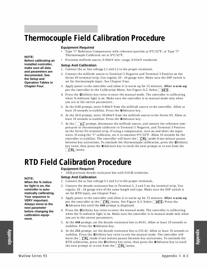
Equipment Required• Type "J" Reference Compensator with reference junction at 0°C/32°F, or Type "J"
Thermocouple Calibrator set at 0°C/32°F.
• Precision millivolt source, 0-50mV min. range, 0.01mV resolution
Setup And Calibration1. Connect the ac line voltage L1 and L2 to the proper terminals.
2. Connect the millivolt source to Terminal 5 Negative and Terminal 3 Positive on theSeries 93 terminal strip. Use regular 20 - 24 gauge wire. Make sure the DIP switch isset for thermocouple input. See Chapter Four.
3. Apply power to the controller and allow it to warm up for 15 minutes. After warm-upput the controller in the Calibration Menu. See Figure A.3. Select [`YES].
4. Press the ˆInfinity key twice to enter the manual mode. The controller is calibratingwhen % indicator light is on. Make sure the controller is in manual mode only whenyou are in the correct parameters.
5. At the 0.00 prompt, enter 0.00mV from the millivolt source to the controller. Allow atleast 10 seconds to stabilize. Press the ‰Advance key.
6. At the 50.0 prompt, enter 50.00mV from the millivolt source to the Series 93. Allow atleast 10 seconds to stabilize. Press the ‰Advance key.
7. At the [``tC] prompt, disconnect the millivolt source, and connect the reference com-pensator or thermocouple calibrator to Terminal 5 Negative, and Terminal 3 Positiveon the Series 93 terminal strip. If using a compensator, turn on and short the inputwires. If using the "J" calibrator, set it to simulate 0°C/32°F. Allow 10 seconds for thecontroller to stabilize. The controller will leave the [`CAL] mode if one minute passesbetween key activations. To conclude the thermocouple calibration, press the ˆInfinitykey twice, then press the ‰Advance key to reach the next prompt or to exit from the[`CAL] menu.
Equipment Required• 1KΩ precision decade resistance box with 0.01Ω resolution.
Setup And Calibration1. Connect the ac line voltage L1 and L2 to the proper terminals.
2. Connect the decade resistance box to Terminal 2, 3 and 5 on the terminal strip. Useregular 20 - 24 gauge wire of the same length and type. Make sure the DIP switch isset for RTD input, see Chapter Four.
3. Apply power to the controller and allow it to warm up for 15 minutes. After warm-upput the controller in the [`CAL] menu. See Figure A.3. Select [`YES]. Press the‰Advance key until the 440 prompt is displayed.
4. Press the ˆInfinity key twice to enter the manual mode. The controller is calibratingwhen the % indicator light is on. Make sure the controller is in manual mode only whenyou are in the correct parameters.
5. At the 440 prompt, set the decade resistance box to 44.01. Allow at least 10 seconds tostabilize. Press the ‰Advance key.
6. At the 255 prompt, set the decade resistance box to 255.42. Allow at least 10 seconds tostabilize. Press the ˆInfinity key twice to exit the manual mode. The controller willleave the [`CAL] mode if one minute passes between key activations. To conclude theRTD calibration, press the ˆInfinity key twice, then press the ‰Advance key to reachthe next prompt or to exit from the [`CAL] menu.
Thermocouple Field Calibration Procedure
RTD Field Calibration Procedure

A.6 Appendix Wat low Ser ies 93
Appendix
Equipment Required• Precision dc voltage source 0-5 volt minimum range with 0.001 volt resolution.
Setup and Calibration 1. Connect the ac line voltage L1 and L2 to the proper terminals on the Series 93.
2. Connect the voltage/current source to Terminal 3 (+) and 5 (-) on the Series 93 terminalstrip. Use regular 20 - 24 gauge wire. Make sure the DIP switch is set for process input,see Chapter Four.
3. Apply power to the controller and allow it to warm up for 15 minutes. After warm-upput the controller in the [`CAL] menu. See Figure A.3. Select [`YES]. Press the‰Advance key until 0.00 is displayed.
4. Press the ˆInfinity key twice to enter the manual mode. The controller is calibratingwhen the % indicator light is on. Make sure the controller is in the manual mode onlywhen you are in the correct parameters.
5. At the 0.00 parameter, set the voltage source to 0.000 volts. Allow at least 10 seconds tostabilize. Press the ‰Advance key.
6. At the 5.00 parameter, set the voltage source to 5.000VÎ (dc). Allow at least 10 secondsto stabilize. The controller leaves the [`CAL] mode if 1 minute passes between key acti-vations. Press the ˆInfinity key twice to exit the manual mode. To conclude the 0-5 voltcalibration, press the ˆInfinity key twice, then press the ‰Advance key to reach thenext prompt or to exit from the [`CAL] menu.
NOTE:When the % indica-tor light is on, thecontroller is auto-matically calibrating.Your sequence isVERY important.Always move to thenext parameterbefore changing thecalibration equip-ment.
NOTE:Before calibrating aninstalled controller,make sure all dataand parameters aredocumented. Seethe Setup andOperation Tables inChapter Four .
0-5 Volt Input Field Calibration Procedure
4-20mA Input Field Calibration ProcedureEquipment Required:• Precision current source 0-20mA minimum range with 0.01mA resolution.
Setup and Calibration 1. Connect the ac line voltage L1 and L2 to the proper terminals on the Series 93.
2. Connect the current source to Terminal 2 (-) and 5 (+) on the Series 93 terminal strip.Use regular 20 - 24 gauge wire. Make sure the DIP switch is set for process input, seeChapter Four.
3. Apply power to the controller and allow it to warm up for 15 minutes. After warm-upput the controller in the [`CAL] menu. See Figure A.3. Select YES. Press the‰Advance key until 4 is displayed.
4. Press the ˆInfinity key twice to enter the manual mode. The controller is calibratingwhen the % indicator light is on. Make sure the controller is in the manual mode onlywhen you are in the correct parameters.
5. At the 4.00 parameter, set the current source to 4.00mA. Allow at least 10 seconds tostabilize. Press the ‰Advance key.
6. At the 20.0 parameter, set the current source to 20.00mA. Allow at least 10 seconds tostabilize. The controller leaves the [`CAL] mode if 1 minute passes between key activa-tions. Press the ˆInfinity key twice to exit the manual mode. To conclude, press theˆInfinity key twice, then press the ‰Advance key to reach the next prompt or to exitfrom the [`CAL] menu.

Watlow Ser ies 93 Appendix A.7
Appe
ndix
Appendix
Equipment Required:• 300Ω, 1/2 watt 10% resistor.
• 4 - 1/2 digit Digital Multimeter.
Setup And Calibration1. Connect the ac line voltage L1 and L2 to the proper terminals of the Series 93. See
Chapter Two. Set the multimeter to measure current.
2. Connect the multimeter in series with the 300Ω resistor to Terminal 9 Positive and 10Negative on the Series 93 terminal strip. Use regular 20 - 24 gauge wire.
3. Apply power to the controller and allow it to warm up for 15 minutes. After warm-upput the controller in the [`CAL] menu. See Figure A.3. Select YES. Press the‰Advance key until the 4A0 prompt is displayed.
4. Press the ˆInfinity key twice to enter the manual mode. The controller is calibratingwhen the % indicator light is on.
5. At the [`4A0] prompt, the multimeter should read approximately 4mA. Allow at least10 seconds to stabilize.
6. Use the ¿Up-arrow/¯Down-arrow keys (reverse acting) to adjust the reading on themultimeter for 3.85mA ± 0.10mA. Press the ‰Advance key.
7. At the [`2A0] prompt, the multimeter should read approximately 20mA. Allow at least10 seconds to stabilize. The controller will leave the [`CAL] mode if one minute passesbetween key activations, except for 4-20mA units.
8. Use the ¿Up/¯Down keys (reverse acting) to adjust the reading on the multimeter for20.15mA ±0.10mA.
9. To conclude the 4-20mA output calibration, press the ˆInfinity key twice, then pressthe ‰Advance key to reach the next prompt or to exit from the [`CAL] menu.
NOTE:Before calibrating aninstalled controller,make sure all dataand parameters aredocumented. Seethe Setup andOperation Tables inChapter Four.
NOTE:When the % indica-tor light is on, thecontroller is auto-matically calibrating.Your sequence isVERY important.Always move to thenext parameterbefore changing thecalibration equip-ment.
4-20mA Output Field Calibration Procedure

A.8 Appendix Wat low Ser ies 93
Appendix
Notes
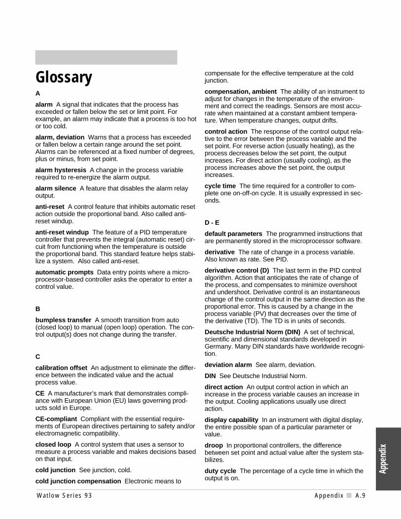
Watlow Ser ies 93 Appendix A.9
GlossaryA
alarm A signal that indicates that the process hasexceeded or fallen below the set or limit point. Forexample, an alarm may indicate that a process is too hotor too cold.
alarm, deviation Warns that a process has exceededor fallen below a certain range around the set point.Alarms can be referenced at a fixed number of degrees,plus or minus, from set point.
alarm hysteresis A change in the process variablerequired to re-energize the alarm output.
alarm silence A feature that disables the alarm relayoutput.
anti-reset A control feature that inhibits automatic resetaction outside the proportional band. Also called anti-reset windup.
anti-reset windup The feature of a PID temperaturecontroller that prevents the integral (automatic reset) cir-cuit from functioning when the temperature is outsidethe proportional band. This standard feature helps stabi-lize a system. Also called anti-reset.
automatic prompts Data entry points where a micro-processor-based controller asks the operator to enter acontrol value.
B
bumpless transfer A smooth transition from auto(closed loop) to manual (open loop) operation. The con-trol output(s) does not change during the transfer.
C
calibration offset An adjustment to eliminate the differ-ence between the indicated value and the actualprocess value.
CE A manufacturer’s mark that demonstrates compli-ance with European Union (EU) laws governing prod-ucts sold in Europe.
CE-compliant Compliant with the essential require-ments of European directives pertaining to safety and/orelectromagnetic compatibility.
closed loop A control system that uses a sensor tomeasure a process variable and makes decisions basedon that input.
cold junction See junction, cold.
cold junction compensation Electronic means to
compensate for the effective temperature at the coldjunction.
compensation, ambient The ability of an instrument toadjust for changes in the temperature of the environ-ment and correct the readings. Sensors are most accu-rate when maintained at a constant ambient tempera-ture. When temperature changes, output drifts.
control action The response of the control output rela-tive to the error between the process variable and theset point. For reverse action (usually heating), as theprocess decreases below the set point, the outputincreases. For direct action (usually cooling), as theprocess increases above the set point, the outputincreases.
cycle time The time required for a controller to com-plete one on-off-on cycle. It is usually expressed in sec-onds.
D - E
default parameters The programmed instructions thatare permanently stored in the microprocessor software.
derivative The rate of change in a process variable.Also known as rate. See PID.
derivative control (D) The last term in the PID controlalgorithm. Action that anticipates the rate of change ofthe process, and compensates to minimize overshootand undershoot. Derivative control is an instantaneouschange of the control output in the same direction as theproportional error. This is caused by a change in theprocess variable (PV) that decreases over the time ofthe derivative (TD). The TD is in units of seconds.
Deutsche Industrial Norm (DIN) A set of technical,scientific and dimensional standards developed inGermany. Many DIN standards have worldwide recogni-tion.
deviation alarm See alarm, deviation.
DIN See Deutsche Industrial Norm.
direct action An output control action in which anincrease in the process variable causes an increase inthe output. Cooling applications usually use directaction.
display capability In an instrument with digital display,the entire possible span of a particular parameter orvalue.
droop In proportional controllers, the differencebetween set point and actual value after the system sta-bilizes.
duty cycle The percentage of a cycle time in which theoutput is on.
Appe
ndix

A.10 Appendix Wat low Ser ies 93
F - G
Form A A single-pole, single-throw relay that uses onlythe normally open (NO) and common contacts. Thesecontacts close when the relay coil is energized. Theyopen when power is removed from the coil.
Form C A single-pole, double-throw relay that uses thenormally open (NO), normally closed (NC) and commoncontacts.
H
hysteresis A change in the process variable required tore-energize the control or alarm output. Sometimescalled switching differential.
I
integral Control action that automatically eliminates off-set, or droop, between set point and actual process tem-perature. See reset, automatic.
integral control (I) A form of temperature control. The Iof PID. See integral.
isolation Electrical separation of sensor from high volt-age circuitry. Allows use of grounded or ungroundedsensing element.
J - K
JIS See Joint Industrial Standards.
Joint Industrial Standards (JIS) A Japanese agencythat establishes and maintains standards for equipmentand components. Also known as JISC (JapaneseIndustrial Standards Committee), its function is similar toGermany’s Deutsche Industrial Norm (DIN).
junction The point where two dissimilar metal conduc-tors join to form a thermocouple.
junction, cold Connection point between thermocouplemetals and the electronic instrument. See referencejunction.
junction, reference The junction in a thermocouple cir-cuit held at a stable, known temperature (cold junction).Standard reference temperature is 32°F (0°C).
L
limit or limit control A highly reliable, discrete safetydevice (redundant to the primary controller) that monitorsand limits the temperature of the process, or a point inthe process. When temperature exceeds or falls belowthe limit set point, the limit controller interrupts power
through the load circuit. A limit control can protect equip-ment and people when it is correctly installed with itsown power supply, power lines, switch and sensor.
M
manual mode A selectable mode that has no automaticcontrol aspects. The operator sets output levels.
N
NEMA 4X A NEMA specification for determining resis-tance to moisture infiltration and corrosion resistance.This rating certifies the controller as washable and corro-sion resistant.
O
offset (process) The difference in temperaturebetween the set point and the actual process tempera-ture. Offset is the error in the process variable that is typ-ical of proportional-only control. See also droop.
on/off A method of control that turns the output full onuntil set point is reached, and then off until the processerror exceeds the hysteresis.
open loop A control system with no sensory feedback.
output Control signal action in response to the differ-ence between set point and process variable.
overshoot The amount by which a process variableexceeds the set point before it stabilizes.
P - Q
P control Proportioning control.
parallel circuit A circuit configuration in which the samevoltage is applied to all components, with current dividedamong the components according to their respectiveresistances or impedances.
parameter A variable that is given a constant value fora specific application or process.
PD control Proportioning control with derivative (rate)action.
percent power control Open loop control with outputpower set at a particular level.
percent power limit Restriction of output power to apredetermined level.
PI control Proportioning control with integral (automaticreset) action.
Appendix

Watlow Ser ies 93 Appendix A.11
PID Proportional, integral, derivative. A control modewith three functions: proportional action dampens thesystem response, integral corrects for droop, and deriva-tive prevents overshoot and undershoot.
process variable The parameter that is controlled ormeasured. Typical examples are temperature, relativehumidity, pressure, flow, fluid level, events, etc. The highprocess variable is the highest value of the processrange, expressed in engineering units. The low processvariable is the lowest value of the process range.
programmed display data Displayed information thatgives the operator the intended process information,such as intended set point, intended alarm limit, etc.,corresponding to temperature.
prompt A symbol or message displayed by the con-troller that requests input from the user.
proportional Output effort proportional to the error fromset point. For example, if the proportional band is 20°and the process is 10° below set point, the heat propor-tioned effort is 50 percent. The lower the PB value, thehigher the gain.
proportional band (PB) A range in which the propor-tioning function of the control is active. Expressed inunits, degrees or percent of span. See PID.
proportional control A control using only the P (pro-portional) value of PID control.
R
rate Anticipatory action that is based on the rate of tem-perature change, and compensates to minimize over-shoot and undershoot. See derivative.
reference junction See junction.
reset Control action that automatically eliminates offset,or droop, between set point and actual process tempera-ture. Also see integral.
reset, automatic The integral function of a PI or PIDtemperature controller that adjusts the process tempera-ture to the set point after the system stabilizes. Theinverse of integral.
reset windup inhibit See anti-reset.
resistance temperature detector (RTD) A sensor thatuses the resistance temperature characteristic to mea-sure temperature. There are two basic types of RTDs:the wire RTD, which is usually made of platinum, andthe thermistor, which is made of a semiconductor materi-al. The wire RTD is a positive temperature coefficientsensor only, while the thermistor can have either a nega-tive or positive temperature coefficient.
reverse action An output control action in which an
increase in the process variable causes a decrease inthe output. Heating applications usually use reverseaction.
RTD See resistance temperature detector.
S
set point The desired value programmed into a con-troller. For example, the temperature at which a systemis to be maintained.
switching sensitivity In on/off control, the temperaturechange necessary to change the output from full on tofull off. See hysteresis.
T - Y
thermal system A regulated environment that consistsof a heat source, heat transfer medium or load, sensingdevice and a control instrument.
thermocouple (t/c) A temperature sensing devicemade by joining two dissimilar metals. This junction pro-duces an electrical voltage in proportion to the differencein temperature between the hot junction (sensing junc-tion) and the leadwire connection to the instrument (coldjunction).
thermocouple break protection The ability of a controlto detect a break in the thermocouple circuit and take apredetermined action.
three-mode control Proportioning control with integral(reset) and derivative (rate). Also see PID.
time proportioning control A method of controllingpower by varying the on/off duty cycle of an output. Thisvariance is proportional to the difference between the setpoint and the actual process temperature.
triac A solid state device that switches alternating cur-rent.
Z
zero cross Action that provides output switching only ator near the zero-voltage crossing points of the ac sinewave. See burst fire.
zero switching See zero cross.
Appe
ndix

A.12 Appendix Wat low Ser ies 93
Appendix
Specifications (1639)Control Mode • Microprocessor-based, user-selectable control modes • Single input, dual output• 2.5Hz Input Sampling Rate• 1Hz Display Update Rate• Ramp to set point: 0 to 9999 degrees or units per hour• Heat and cool autotune Operator Interface • Sealed membrane front panel • Dual, four-digit red or green displays • ‰Advance, ¿Up-arrow, ¯Down-arrow, and ˆInfinity keys • User-selectable screen display Accuracy • Calibration accuracy and sensor conformity: ±0.1% of span, ±1°C
@ 25°C ± 3°C (77°F ± 5°F) ambient and rated line voltage • Accuracy span: 540°C (1000°F) minimum• Temperature stability: ±0.2°C/°C (±0.2°F/°F) rise in ambient maxi-
mum Sensors/Inputs • Thermocouple, grounded or ungrounded sensors• RTD 2- or 3-wire, platinum, 100Ω @ 0°C calibration to DIN curve
(0.00385Ω/Ω/°C) or JIS curve (0.003916Ω/Ω/°C); user-selectable • Process, 4-20mA @ 5Ω, or 0-5VÎ (dc) @ 10kΩ input impedance • Sensor break protection de-energizes control output to protect
system or selectable bumpless transfer to manual operation• °C or °F or process units display, user-selectableInput Range
Specified temperature ranges represent the controller’s operation-al span.
• ThermocoupleType J 0 to 750°C
(32 to 1382°F)Type K -200 to 1250°C
(-328 to 2282°F)Type N 0 to 1250°C
(32 to 2282°F)Type S 0 to 1450°C
(32 to 2642°F)Type T -200 to 350°C
(-328 to 662°F)• RTD Resolution (DIN or JIS)
1° -200 to 700°C(-328 to 1292°F)
0.1° -128.8 to 537.7°C(-199.9 to 999.9°F)
• Process4-20mA @ 5Ω, or -999 to 9999 units0-5V (dc) @ 10kΩ, or -999 to 9999 units
Output 1 (Heating or Cooling)• Electromechanical relay1, Form C, 5A @ 120/240V~ (ac) maxi-
mum, without contact suppression, rated resistive load, 5A @30VÎ (dc)3. Minimum contact current, 100mA @ 5VÎ (dc).
• Switched dc signal provides a non-isolated minimum turn on volt-age of 3VÎ (dc) into a minimum 500Ω load; maximum on voltagenot greater than 12VÎ (dc) into an infinite load.
• 4-20mA reverse or direct acting, non-isolated 0 to 800Ω load.• Solid-state relay3, Form A, 0.5A @ 24V~ (ac) min., 264V~ (ac)
max., opto-isolated burst fire switched, without contact suppres-sion. Off-state output impedance is 31MΩ.
Output 2 (Heat, Cool or Alarm)• Electromechanical relay1, Form C, 5A @ 120/240V~ (ac) maxi-
mum, without contact suppression, rated resistive load, 5A @30VÎ (dc)3. Minimum contact current, 100mA @ 5VÎ (dc).
• Switched dc signal provides a non-isolated minimum turn on volt-age of 3VÎ (dc) into a minimum 500Ω load; maximum on voltagenot greater than 12VÎ (dc) into an infinite load.
• Solid-state relay3, Form A, 0.5A @ 24V~ (ac) min., 264V~ (ac)max., opto-isolated burst fire switched, without contact suppres-sion. Off-state output impedance is 31MΩ.
• Alarm output can be latching or non-latching, and process or devi-ation with separate high and low values. Alarm silencing (inhibit)on power up (for deviation alarms only).
Output Configurations• Output 1User-selectable as: on-off: P, PI, PD, PID, heat or cool action• Adjustable switching differential: 1 to 55°C (1 to 99°F)• Proportional band: 0 (off) or 0 to 555°C (1 to 999°F) or 0.0 to
999.9 unitsIntegral: 0 (off) or 0.1 to 99.9 minutes per repeatReset: 0 (off) or 0.01 to 9.99 repeats per minuteRate/derivative: 0 (off) or 0.01 to 9.99 minutesCycle time: 0.1 to 999.9 seconds
• Output 2User selectable as: Control with action opposite that of Output 1
(heating or cooling)• Process or deviation alarm with flashing alarm message• Process or deviation alarm without alarm message• Alarm with separate high and low set points• Hysteresis: 1 to 9999° or units switching differentialLine Voltage/Power• 100-240V~ (ac), -15%, +10%4; (85-264V~ [ac]) 50/60Hz, ±5%• 12-24Vı (ac/dc), +10%, -15%; (10-26Vı [ac/dc]) 50/60Hz, ±5%• Fused internally(factory replaceable only) Slo-Blo® type (time-lag):
1A, 250V for high voltage versions2A, 250V for low voltage versions
• Maximum power consumption: 12VA (100 to 240V~), 7VA (12 to24Vı)
• Data retention upon power failure via non-volatile memoryOperating Environment4• 0 to 65°C (32 to 149°F).• 0 to 90% RH, non-condensingStorage Temperature• -40° to 85°C (-40° to 185°F)Terminals• #6 compression universal head screw terminals, accepts 20-14
gauge wireController Weight• 0.2 kg (0.4 lb)Shipping Weight• 0.34 kg (0.75 lb)Dimensions• Compact 1⁄16 DIN size and IP652 (NEMA 4X), front panel make
the Series 93 easy to apply and maintain in a wide variety ofapplications. The unique mounting bezel, gasket and collar makeinstallation a snap.Overall Height: 55 mm (2.1 inches)
Width: 55 mm (2.1 inches)Depth: 120 mm (4.7 inches)
Bezel Height: 55 mm (2.1 inches)Width: 55 mm (2.1 inches)Depth: 15 mm (0.6 inches)
Chassis Height: 45 mm (1.8 inches)Width: 45 mm (1.8 inches)Depth: 105 mm (4.1 inches)
Agency Approvals• UL508®, c-UL, CE, IP65 (NEMA 4X), File #E102269• CE:
89/336/EEC (EN 50082-2, EN 50081-2)73/23/EEC (EN61010-1)
1 Electromechanical relays warranted for 100,000 closures only.Solid-state switching devices recommended for applicationsrequiring fast cycle times or extended service life.
2 To effect IP65 (NEMA 4X) rating requires a minimum mountingpanel thickness of 1.5 mm (0.06 inch) and surface finish notrougher than 0.000812 mm (0.000032 inch).
3 Switching inductive loads (relay coils, etc.) requires using an RCsuppressor.
4 Operating environment is 0 to 60°C for live voltage exceeding 240V.
Specifications
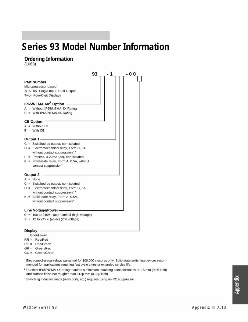
Ordering Information(1068)
93 _ _ - 1 _ _ _ - 0 0_ _
Part NumberMicroprocessor-based1/16 DIN, Single Input, Dual Output,Two-, Four-Digit Displays
IP65/NEMA 4X2 OptionA = Without IP65/NEMA 4X Rating B = With IP65/NEMA 4X Rating
CE OptionA = Without CE B = With CE
Output 1C = Switched dc output, non-isolatedD = Electromechanical relay, Form C, 5A,
without contact suppression1, 3
F = Process, 4-20mA (dc), non-isolatedK = Solid-state relay, Form A, 0.5A, without
contact suppression3
Output 2A = NoneC = Switched dc output, non-isolatedD = Electromechanical relay, Form C, 5A,
without contact suppression1, 3
K = Solid-state relay, Form A, 0.5A, without contact suppression3
Line Voltage/Power0 = 100 to 240V~ (ac) nominal (high voltage)1 = 12 to 24Vı (ac/dc) (low voltage)
DisplayUpper/Lower
RR = Red/RedRG = Red/GreenGR = Green/RedGG = Green/Green
1 Electromechanical relays warranted for 100,000 closures only. Solid-state switching devices recom-mended for applications requiring fast cycle times or extended service life.
2 To effect IP65/NEMA 4X rating requires a minimum mounting panel thickness of 1.5 mm (0.06 inch)and surface finish not rougher than 812µ mm (0.32µ inch).
3 Switching inductive loads (relay coils, etc.) requires using an RC suppressor.
Watlow Ser ies 93 Appendix A.13
Appe
ndix
Series 93 Model Number Information

A.14 Appendix Wat low Ser ies 93
Appendix
A‰Advance key 3.1Alarm High 4.7Alarm Low 4.7alarm silencing 5.5alarms 5.4automatic operation 5.3autotuning 5.1Autotune 4.7
B - Ccalibration A.3Calibration Menu A.4Calibration Offset 4.7Celsius-Fahrenheit 4.3clearing an alarm 5.4Cycle Time 4.6
Ddefault parameters
Operation 4.6-4.7Setup 4.3-4.5
Derivative 4.6Deviation alarm 5.4dimensions
faceplate 2.1panel cutout 2.1side view 2.1
DIP Switches 4.1Display 3.1, 4.5¯Down-arrow key 3.1
Eentering the Setup Menu 4.2error codes 5.5-5.6
Ffield calibration A.5-A.7
Ggeneral description 1.1Glossary A.9
Hhigh voltage wiring 2.3Hysteresis 4.4
Iindicator lights 3.1ˆInfinity key 3.1Input
wiring 2.4DIP Switch 4.1ranges 4.5RTD 4.4thermocouple 2.4type 4.3
Integral 4.6
J - KKeys 3.1
Lladder wiring diagram 2.9Latching 4.4, 5.4Lock Parameter 4.3low voltage wiring 2.3Lower Display 3.1
Mmanual operation 5.3manual tuning 5.2mechanical relay, 5 Amp
Output 1 Wiring 2.6Output 2 Wiring 2.8
Model Number A.13mounting collar 2.2mounting case 2.2
NNoise
eliminating A.2sources A.1decreasing sensitivity A.1
OOperation Menu 4.6-4.7Operation Parameters 4.6Output 1 4.4Output 2 4.4Output Wiring
5A Mechanical Relay 2.6, 2.84-20mA 2.7switched dc 2.7, 2.8solid-state relay 2.6, 2.8
overview of the Series 93 1.1
P%Percent Power Indicator Light 3.1Power Limiting 4.5power wiring 2.3process alarm 5.4process input 2.5Proportional Band 4.6
QQuick Reference Sheet A.17-A.18
RRamping 4.4Range High 4.4Range Low 4.3Rate 4.6removing controller 2.2Reset 4.6restoring calibration A.4
returns back coverRTD Calibration A.5RTD Sensor Wiring 2.4
Ssensor installation 2.4Set Point 4.6Setup Menu 4.1, 4.2Setup Parameters 4.3Silencing 4.4Specifications A.12
Tthermocouple calibration A.5thermocouple sensor wiring 2.4tuning 5.1-5.3
U - Z¿Up-arrow key 3.1Upper Display 3.1warranty back coverwiring 2.3wiring example 2.9
Index

Watlow Ser ies 93 Appendix A.15
Appe
ndix
Declara que el producto siguiente: EspañolDesignación: Serie 93Números de modelo: 9 3 (A o B) (A o B) - 1 (C D F o K) (A C D o K) (0 ó 1) -
(Cualquier combinación de cuatro números y letras)Clasificación: Control, categoría de instalación II, grado de
contaminación ambiental IITensión nominal: 100 a 240 V o 24 Frecuencia nominal: 50/60 HzConsumo nominalde energía: 6 VA máximo
Cumple con los requisitos esenciales de las siguientes directivas de la UniónEuropea, usando las secciones pertinentes de las reglas normalizadas y losdocumentos relacionados que se muestran:
89/336/EEC Directiva de Compatibilidad ElectromagnéticaEN 50082-2: 1995 Norma de inmunidad genérica del EMC, Parte 2:
Ambiente industrialEN 61000-3-2 1995 Límites para corriente armónicaEN 61000-3-3 1995 Limitaciones de oscilaciones y fluctuaciones de voltajeEN 61000-4-2: 1995 Descarga electrostáticaEN 61000-4-4: 1995 Perturbaciones transitorias eléctricas rápidasEN 61000-4-3: 1996 Inmunidad radiadaEN 61000-4-6: 1996 Inmunidad conducidaENV 50204: 1995 Teléfono portátilEN 50081-2: 1994 Norma de emisión genérica del EMC, Parte 2: Ambiente
industrialEN 55011: 1991 Límites y métodos para medición de características de
perturbaciones de radio correspondientes a equipos deradiofrecuencia industriales, científicos y médicos (Grupo 1,Clase A)
EN 61000-3-2: 1995 Límites para emisiones de corriente armónicaEN 61000-3-3: 1995 Limitaciones de fluctuaciones del voltaje
73/23/EEC Directiva de Baja TensiónEN 61010-1: 1993 Requerimientos de seguridad para equipos eléctricos de
medición, control y uso en laboratorios,Parte 1: Requerimientos generales
Erwin D. Lowell Winona, Minnesota, USAName of Authorized Representative Place of IssueGeneral Manager November, 1997Title of Authorized Representative Date of Issue
________________________________________Signature of Authorized Representative
Declaration of Conformity
Series 93
WATLOW CONTROLS1241 Bundy BoulevardWinona, Minnesota 55987 USA
Declares that the following product: EnglishDesignation: Series 93Model Number(s): 93(A or B) (A or B) - 1 (C D F or K) (A C D or K) (0 or
1) - (Any four letters or numbers)Classification: Control, Installation Category II, Polution Degree IIRated Voltage: 100 to 240V or 24 Rated Frequency: 50/60 HzRated Power Consumption: 6VA maximum
Meets the essential requirements of the following European Union Directive(s) usingthe relevant section(s) of the normalized standards and related documents shown:
89/336/EEC Electromagnetic Compatibility DirectiveEN 50082-2: 1995 EMC Generic immunity standard, Part 2: Industrial
environmentEN 61000-3-2: 1995 Limits for harmonic currentEN 61000-3-3: 1995 Limitations of voltage fluctuatuions and flickerEN 61000-4-2: 1995 Electrostatic dischargeEN 61000-4-4: 1995 Electrical fast transientsEN 61000-4-3: 1996 Radiated immunityEN 61000-4-6: 1996 Conducted immunityENV 50204: 1995 Cellular phoneEN 50081-2: 1994 EMC Generic emission standard, Part 2: Industrial
environmentEN 55011: 1991 Limits and methods of measurement of radio
disturbance characteristics of industrial, scientific and medicalradio-frequency equipment (Group 1, Class A)
EN 61000-3-2: 1995 Limits for harmonic current emissionsEN 61000-3-3: 1995 Limitations of voltage fluctuations and flicker
73/23/EEC Low-Voltage DirectiveEN 61010-1: 1993 Safety requirements for electrical equipment for
measurement, control, and laboratory use,Part 1: General requirements
Déclare que le produit suivant : FrançaisDésignation : Série 93Numéro(s) de modèle(s) : 93(A ou B)(A ou B)-1(C, D, F ou K) (A, C, D ou K) (0
ou 1) - (quatre lettres ou chiffres quelconques)Classification : Commande, installation catégorie II, degré de
pollution IITension nominale : 100 à 240 V ou 24Fréquence nominale : 50/60 HzConsommationd’alimentation nominale : 6 VA maximum
Conforme aux exigences de la (ou des) directive(s) suivante(s) de l’UnionEuropéenne figurant aux sections correspondantes des normes et documentsassociés ci-dessous :
89/336/EEC Directive de compatibilité électromagnétiqueEN 50082-2 : 1995 Norme générique d’insensibilité électromagnétique,
Partie 2 : Environnement industrielEN 61000-3-2 : 1995 Limites de courant harmoniqueEN 61000-3-3 : 1995 Limites de fluctuation et de vacillement de la tensionEN 61000-4-2 : 1995 Décharge électrostatiqueEN 61000-4-4 : 1995 Courants électriques transitoires rapidesEN 61000-4-3: 1996 Insensibilité à l’énergie rayonnéeEN 61000-4-6: 1996 Insensibilité à l’énergie par conductionENV 50204 : 1995 Téléphone cellulaireEN 50081-2 : 1994 Norme générique sur les émissions électromagnétiques,
Partie 2 : Environnement industrielEN 55011 : 1991 Limites et méthodes de mesure des caractéristiques
d’interférences du matériel radiofréquence industriel,scientifique et médical (Groupe 1, Classe A)
EN 61000-3-2 : 1995 Limites d’émission d’harmoniquesEN 61000-3-3 : 1995 Limitations d’écarts de tension et de papillotement
73/23/EEC Directive liée aux basses tensionsEN 61010-1 : 1993 Exigences de sécurité pour le matériel électrique de
mesure, de commande et de laboratoire,Partie 1 : Exigences générales
97 Erklärt, daß das folgende Produkt: DeutschBeschreibung: Serie 93Modellnummer(n): 9 3 (A oder B) (A oder B) - 1 (C D F oder K) (A C D oder
K) (0 oder 1) - (4 beliebige Buchstaben oder Ziffern)Klassifikation: Regelsystem, Installationskategorie II, Emissionsgrad IINennspannung: 100 bis 240 V oder 24 bis 28 VNennfrequenz: 50/60 HzNominalerStromverbrauch: Max. 6 VA
Erfüllt die wichtigsten Normen der folgenden Anweisung(en) der EuropäischenUnion unter Verwendung des wichtigsten Abschnitts bzw. der wichtigsten Abschnitteder normalisierten Spezifikationen und der untenstehenden einschlägigenDokumente:
89/336/EEC Elektromagnetische ÜbereinstimmungsanweisungEN 50082-2: 1995 EMC-Rahmennorm für Störsicherheit, Teil 2: Industrielle
UmweltEN 61000-3-2: 1995 Grenzen der OberwellenstromemissionEN 61000-3-3: 1995 Grenzen der Spannungsschwankungen und FlimmernEN 61000-4-2: 1995 Elektrostatische EntladungEN 61000-4-4: 1995 Elektrische schnelle StößeEN 61000-4-3: 1996 StrahlungsimmunitätEN 61000-4-6: 1996 StörimmunitätENV 50204: 1995 MobiltelefonEN 50081-2: 1994 EMC-Rahmennorm für Emissionen, Teil 2: Industrielle
UmweltEN 55011: 1991 Beschränkungen und Methoden der Messung von
Funkstörungsmerkmalen industrieller, wissenschaftlicher undmedizinischer Hochfrequenzgeräte (Gruppe 1, Klasse A)
EN 61000-3-2: 1995 Grenzen der OberwellenstromemissionenEN 61000-3-3: 1995 Grenzen der Spannungsschwankungen und Flimmern
73/23/EEC Niederspannungsrichtlinie zu entsprechenEN 61010-1: 1993 Sicherheitsrichtlinien für Elektrogeräte zur Messung, zur
Steuerung und im Labor,Teil 1: Allgemeine Richtlinien
(1505)

A.16 Appendix Wat low Ser ies 93
Notes
Appendix
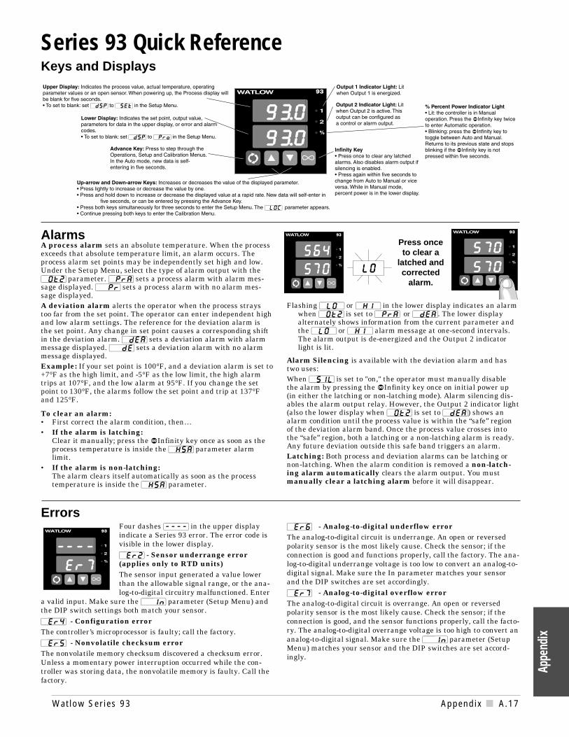
Errors Four dashes [----] in the upper displayindicate a Series 93 error. The error code isvisible in the lower display.[`Er2] - Sensor underrange error(applies only to RTD units)The sensor input generated a value lowerthan the allowable signal range, or the ana-log-to-digital circuitry malfunctioned. Enter
a valid input. Make sure the [``In] parameter (Setup Menu) andthe DIP switch settings both match your sensor. [`Er4] - Configuration errorThe controller’s microprocessor is faulty; call the factory.[`Er5] - Nonvolatile checksum errorThe nonvolatile memory checksum discovered a checksum error.Unless a momentary power interruption occurred while the con-troller was storing data, the nonvolatile memory is faulty. Call thefactory.
[`Er6] - Analog-to-digital underflow errorThe analog-to-digital circuit is underrange. An open or reversedpolarity sensor is the most likely cause. Check the sensor; if theconnection is good and functions properly, call the factory. The ana-log-to-digital underrange voltage is too low to convert an analog-to-digital signal. Make sure the In parameter matches your sensorand the DIP switches are set accordingly.[`Er7] - Analog-to-digital overflow errorThe analog-to-digital circuit is overrange. An open or reversedpolarity sensor is the most likely cause. Check the sensor; if theconnection is good, and the sensor functions properly, call the facto-ry. The analog-to-digital overrange voltage is too high to convert ananalog-to-digital signal. Make sure the [``In] parameter (SetupMenu) matches your sensor and the DIP switches are set accord-ingly.
Series 93 Quick ReferenceKeys and Displays
Watlow Ser ies 93 Appendix A.17
Appe
ndix
AlarmsA process alarm sets an absolute temperature. When the processexceeds that absolute temperature limit, an alarm occurs. Theprocess alarm set points may be independently set high and low.Under the Setup Menu, select the type of alarm output with the[`Ot2] parameter. [`PrA] sets a process alarm with alarm mes-sage displayed. [``Pr] sets a process alarm with no alarm mes-sage displayed.A deviation alarm alerts the operator when the process straystoo far from the set point. The operator can enter independent highand low alarm settings. The reference for the deviation alarm isthe set point. Any change in set point causes a corresponding shiftin the deviation alarm. [`dEA] sets a deviation alarm with alarmmessage displayed. [``dE] sets a deviation alarm with no alarmmessage displayed. Example: If your set point is 100°F, and a deviation alarm is set to+7°F as the high limit, and -5°F as the low limit, the high alarmtrips at 107°F, and the low alarm at 95°F. If you change the setpoint to 130°F, the alarms follow the set point and trip at 137°Fand 125°F.
To clear an alarm:• First correct the alarm condition, then…• If the alarm is latching:
Clear it manually; press the ˆInfinity key once as soon as theprocess temperature is inside the [`HSA] parameter alarmlimit.
• If the alarm is non-latching:The alarm clears itself automatically as soon as the processtemperature is inside the [`HSA] parameter.
Flashing [`LO`] or [`HI`] in the lower display indicates an alarmwhen [`Ot2] is set to [`PrA] or [`dEA]. The lower displayalternately shows information from the current parameter andthe [`LO`] or [`HI`] alarm message at one-second intervals.The alarm output is de-energized and the Output 2 indicatorlight is lit.
Alarm Silencing is available with the deviation alarm and hastwo uses:When [`SIL] is set to "on," the operator must manually disablethe alarm by pressing the ˆInfinity key once on initial power up(in either the latching or non-latching mode). Alarm silencing dis-ables the alarm output relay. However, the Output 2 indicator light(also the lower display when [`Ot2] is set to [`dEA]) shows analarm condition until the process value is within the “safe” regionof the deviation alarm band. Once the process value crosses intothe “safe” region, both a latching or a non-latching alarm is ready.Any future deviation outside this safe band triggers an alarm.Latching: Both process and deviation alarms can be latching ornon-latching. When the alarm condition is removed a non-latch-ing alarm automatically clears the alarm output. You mustmanually clear a latching alarm before it will disappear.
Press once to clear a
latched andcorrected
alarm.

A.18 Appendix Wat low Ser ies 93
Appendix
Parameter Value Range Factory Default Appears If:[`LOC] 0 - 4 0
[``In] [```J], [```H], [```t], [```n], [```J] DIP switch-selectable.
[```S][`rtd], [`r†d], [`0-5], [`420]
[`dEC] 0, 0.0, 0.00 0 [``In] is set to [`0-5]
or [`420]
[`C_F] [```C] or [```F] Dependent on [`dFL] [``In] is set to [```J],
[```H], [```t], [```n],
[```S], [`rtd], or [`r†d]
[``rL] [``rL] to [``rh] Input dependent.
[``rh] [``rh] to [``rL] Input dependent.
[`Ot1] [``ht] or [``CL] [``ht]
[`HSC] 1 to 55, 0.1 to 5.5, 0.01 to 0.55°C 2, 0.2, 0.02°C
1 to 99, 0.1 to 9.9, 0.01 to 0.99°F 3, 0.3, 0.03°F[`Ot2] [`Con] Control [`Con]
[`PrA] Process Alarm[``Pr] Process with no alarm message[`dEA] Deviation alarm[``dE] Deviation with no alarm message[``no] None
[`HSA] 1 to 5555, 0.1 to 555.5, 0.01 to 55.55°C 2, 0.2, 0.02°C [`Ot2] is not set to [`Con]
1 to 9999, 0.1 to 999.9, 0.01 to 99.99oF 3, 0.3, 0.03°F or [``no]
[`LAt] [`LAt] or [`nLA] [`nLA] [`Ot2] is not set to [`Con]
or [``no]
[`SIL] [``On] or [`OFF] [`OFF] [`Ot2] is set to [`dEA] or
[``dE]
[`rtd] [`JIS] or [`din] [`din] [``In] is set to [`rtd] or
[`r†d]
[`rP`] [`Str] is set to Ramping on power up [`OFF]
[``on] is set to Ramping to set point always
[`OFF] is set to None
[`rt`] 0 to 9999 100°/hr [``rP] is not set to [`OFF]
[`P`L] 0 to 100 100
[`dsP] [`nor] normal [`nor]
[`SEt] Set Point (lower only)
[`Pro] Process (upper only)
Parameter Value Range Factory Default[`Pb1] If [`dFL] is set to [``US]:
0 to 555°C/0 to 999°F/0 to 999 Units 25°F0 to 55.5°C/0 to 99.9°F/0 to 99.9 Units 2.5°F0 is set to on-off control. [`HSC] is set to switch differentialIf [`dFL] is set to [``SI]:0.0 to 999.9% of span 3%
[`rE1] 0.00 to 9.99 repeats/minute 0.00 repeats/minute0.00 = No Reset. Won't appear if [`Pb1] is set to 0or [`dFL] is set to [``SI].
[`It1] 0.0 to 99.9 minutes/rpt. 0.00 = No Integral. 00.0 minutes/repeatWon't appear if [`Pb1] is set to 0 or [`dFL] is set to [``US].
[`rA1] 0.00 to 9.99 minutes 0.00 minutes0.00 = No Rate. Will not appear if [`Pb1] is set to 0or [`dFL] is set to [``SI].
[`dE1] 0.00 to 9.99 minutes. 0.00 = No Derivative. 0.00 minutesWon't appear if [`Pb1] is set to 0 or [`dFL] is set to [``US].
[`Ct1] 0.1 to 999.9 5.0 secondsWon't appear if [`Pb1] = 0, or [`420].
[`Pb2] Same as [`Pb1]. [`Pb2] lower limit = 1, 0.1, 0.01
[`rE2] Same range as [`rE1].
[`It2] Same range as [`It1].
[`rA2] Same range as [`rA1].
[`dE2] Same range as [`dE1].
[`Ct2] Same range as [`Ct1].
[`ALO]
Deviation [``dE] -999 to 0 -999Process [``Pr] [``rL] to [`AHI] [``rL]
Will not appear if [`Ot2] is set to [``no] or [`Con].
[`AHI]
Deviation [``dE] 0 to 999 999Process [``Pr] [`ALO] to [``rH] [``rH]
Will not appear if [`Ot2] is set to [``no] or [`Con].
[`CAL] ±100°C/±180°F/±180 Units 0
[`AUt] 0 to 3 0
Setup Menu
Operation Menu
93
93
Enter the Setup Menu bypressing the ¿Up-arrow and¯Down-arrow keys simulta-neously for three seconds. Thelower display shows the[`LOC] Lock parameter, andthe upper display shows itscurrent level. All keys areinactive until you release bothkeys. You can reach the Lockparameter from anywhere.Use the ‰Advance key tomove through the menus andthe ¿Up-arrow and ¯Down-arrow keys to select data. Youwill not see all parameters inthis menu, depending on thecontroller's configuration andmodel number.
Note:Do not enter any values here;make photocopies instead.

Watlow ControlsWatlow Controls is a division of Watlow Electric Mfg. Co., St. Louis, Missouri, amanufacturer of industrial electric heating products, since 1922. Watlow beginswith a full set of specifications and completes an industrial product that is manu-factured totally in-house, in the U.S.A. Watlow products include electric heaters,sensors, controls and switching devices. The Winona operation has been design-ing solid-state electronic control devices since 1962, and has earned the reputa-tion as an excellent supplier to original equipment manufacturers. These OEMsdepend upon Watlow Controls to provide compatibly engineered controls thatthey can incorporate into their products with confidence. Watlow Controls residesin a 100,000-square-foot marketing, engineering and manufacturing facility inWinona, Minnesota.

Watlow Series 93 User’s ManualWatlow Controls, 1241 Bundy Blvd., P.O. Box 5580, Winona, MN 55987-5580, Phone: 507/454-5300, Fax: 507/452-4507
How to Reach Us
Quality andMissionStatement:Watlow Controls will bethe world’s bestsupplier of industrialtemperature controlproducts, services, andsystems by exceedingour customers’,employees’, andshareholders’expectations.
Contact
• or Phone: 507/454-5300.
• Fax: 507/452-4507.
• For technical support, ask for an Applications Engineer.
• To place an order, ask for Customer Service.
• To discuss a custom option, ask for a Series 93 Product Manager.
WarrantyThe Watlow Series 93 is warranted to be free of defects in material and work-manship for 36 months after delivery to the first purchaser for use, providingthat the units have not been misapplied. Since Watlow has no control over theiruse, and sometimes misuse, we cannot guarantee against failure. Watlow’sobligations hereunder, at Watlow’s option, are limited to replacement, repair orrefund of purchase price, and parts which upon examination prove to be defec-tive within the warranty period specified. This warranty does not apply to dam-age resulting from transportation, alteration, misuse, or abuse.
Returns• Call or fax Customer Service for a Return Material Authorization (RMA)
number before returning a controller.• Put the RMA number on the shipping label, and also on a description of the
problem.• 20% of net price restocking charge applies to all standard units returned to
stock.
TOTAL
3 Year Warranty
CUSTOMERSATISFACTION
Your Authorized Watlow Distributor is: