Series 50 T (M1310A) Fetal Telemetry System
76
Series 50 T (M1310A) Fetal Telemetry System INSTRUCTIONS FOR USE M1310-9001B Printed in Germany December 2001 Edition 1
Transcript of Series 50 T (M1310A) Fetal Telemetry System

Series 50 T (M1310A)Fetal Telemetry System
I N S T R U C T I O N S F O R U S EM1310-9001B
Printed in Germany December 2001
Edition 1

Philips makes no warranty of any kind with regard to this material, including, but not limited to, the implied warranties of merchantability and fitness for a particular purpose. Philips shall not be liable for errors contained herein or for incidental or consequential damages in connection with the furnishing, performance or use of this material.
The information contained in this document is subject to change without notice.
Philips assumes no responsibility for the use or reliability of its software on equipment that is not furnished by Philips.
Responsibility of the Manufacturer
Philips only considers itself responsible for any effects on safety, reliability and performance of the equipment if:
• assembly operations, extensions, re-adjustments, modifications or repairs are carried out by persons authorized by Philips, and
• the electrical installation of the relevant room complies with national standards, and
• the instrument is used in accordance with the Instructions for Use or User’s Guide.
The following conventions for cautions and warnings are used in this guide:
CautionA caution calls attention to a condition or possible situation that could damage or destroy the product or the user’s work.
WarningA warning calls attention to a condition or possible situation that could cause injury to the user and/or patient.
2001 Philips Medizinsysteme GmbH
All rights are reserved. Reproduction in whole or in part is prohibited without the prior written consent of the copyright holder.

Contents
1. Safety . . . . . . . . . . . . . . . . . . . . . . . . . . . . . . . . . . . . . . . . . . . . . . . . . . . . . . . 1
Warnings . . . . . . . . . . . . . . . . . . . . . . . . . . . . . . . . . . . . . . . . . . . . . . . . . . . . . . . . . . . . . . 1Cautions . . . . . . . . . . . . . . . . . . . . . . . . . . . . . . . . . . . . . . . . . . . . . . . . . . . . . . . . . . . . . . . 3Patient Safety . . . . . . . . . . . . . . . . . . . . . . . . . . . . . . . . . . . . . . . . . . . . . . . . . . . . . . . . . . . 5Environment . . . . . . . . . . . . . . . . . . . . . . . . . . . . . . . . . . . . . . . . . . . . . . . . . . . . . . . . . . . . 5Safety Symbols . . . . . . . . . . . . . . . . . . . . . . . . . . . . . . . . . . . . . . . . . . . . . . . . . . . . . . . . . . 6Protective Earth . . . . . . . . . . . . . . . . . . . . . . . . . . . . . . . . . . . . . . . . . . . . . . . . . . . . . . . . . 7Maximum Input/Output Voltages . . . . . . . . . . . . . . . . . . . . . . . . . . . . . . . . . . . . . . . . . . . 8
2. Overview . . . . . . . . . . . . . . . . . . . . . . . . . . . . . . . . . . . . . . . . . . . . . . . . . . . . 9
Intended Use Statement (M1310A) . . . . . . . . . . . . . . . . . . . . . . . . . . . . . . . . . . . . . . . . . . 9About This Book . . . . . . . . . . . . . . . . . . . . . . . . . . . . . . . . . . . . . . . . . . . . . . . . . . . . . . . 10Compatible Fetal Monitors . . . . . . . . . . . . . . . . . . . . . . . . . . . . . . . . . . . . . . . . . . . . . . . 10Product Overview . . . . . . . . . . . . . . . . . . . . . . . . . . . . . . . . . . . . . . . . . . . . . . . . . . . . . . 11Application Overview . . . . . . . . . . . . . . . . . . . . . . . . . . . . . . . . . . . . . . . . . . . . . . . . . . . 15
3. Setting Up the System . . . . . . . . . . . . . . . . . . . . . . . . . . . . . . . . . . . . . . . . . 17
Unpacking the Telemetry System . . . . . . . . . . . . . . . . . . . . . . . . . . . . . . . . . . . . . . . . . . 17Connecting and Assembling the Antenna . . . . . . . . . . . . . . . . . . . . . . . . . . . . . . . . . . . . 19
Remote Antenna . . . . . . . . . . . . . . . . . . . . . . . . . . . . . . . . . . . . . . . . . . . . . . . . . . . . 19Local Antenna . . . . . . . . . . . . . . . . . . . . . . . . . . . . . . . . . . . . . . . . . . . . . . . . . . . . . . 19
Connecting the Receiver to the Fetal Monitor . . . . . . . . . . . . . . . . . . . . . . . . . . . . . . . 21Connecting Power . . . . . . . . . . . . . . . . . . . . . . . . . . . . . . . . . . . . . . . . . . . . . . . . . . . . . 23Setting Up the Transmitter . . . . . . . . . . . . . . . . . . . . . . . . . . . . . . . . . . . . . . . . . . . . . . 24
4. Monitoring . . . . . . . . . . . . . . . . . . . . . . . . . . . . . . . . . . . . . . . . . . . . . . . . . . 25
Prerequisites. . . . . . . . . . . . . . . . . . . . . . . . . . . . . . . . . . . . . . . . . . . . . . . . . . . . . . . . . . . 25Underwater Monitoring . . . . . . . . . . . . . . . . . . . . . . . . . . . . . . . . . . . . . . . . . . . . . . . . . 25Switching On the Receiver and the Fetal Monitor . . . . . . . . . . . . . . . . . . . . . . . . . . . . . 26Switching On the Transmitter . . . . . . . . . . . . . . . . . . . . . . . . . . . . . . . . . . . . . . . . . . . . . 27Monitoring Ambulant FHR Using Ultrasound . . . . . . . . . . . . . . . . . . . . . . . . . . . . . . . . . 29Monitoring Ambulant FHR Using DECG. . . . . . . . . . . . . . . . . . . . . . . . . . . . . . . . . . . . . 30Monitoring Ambulant Toco . . . . . . . . . . . . . . . . . . . . . . . . . . . . . . . . . . . . . . . . . . . . . . . 31Monitoring Ambulant Intrauterine Pressure (IUP) . . . . . . . . . . . . . . . . . . . . . . . . . . . . . 32Solving Common Monitoring Problems . . . . . . . . . . . . . . . . . . . . . . . . . . . . . . . . . . . . 33
Contents iii

5. Fetal Movement Profile . . . . . . . . . . . . . . . . . . . . . . . . . . . . . . . . . . . . . . . 35
Prerequisites . . . . . . . . . . . . . . . . . . . . . . . . . . . . . . . . . . . . . . . . . . . . . . . . . . . . . . . . . . . 35Solving Common Problems . . . . . . . . . . . . . . . . . . . . . . . . . . . . . . . . . . . . . . . . . . . . . . . 35
6. Marking Events . . . . . . . . . . . . . . . . . . . . . . . . . . . . . . . . . . . . . . . . . . . . . . 37
Remote Event Marker. . . . . . . . . . . . . . . . . . . . . . . . . . . . . . . . . . . . . . . . . . . . . . . . . . . . 37Setting Up the Marker . . . . . . . . . . . . . . . . . . . . . . . . . . . . . . . . . . . . . . . . . . . . . . . . . . . 37
7. Nurse Call . . . . . . . . . . . . . . . . . . . . . . . . . . . . . . . . . . . . . . . . . . . . . . . . . . 41
Using the Nurse Call. . . . . . . . . . . . . . . . . . . . . . . . . . . . . . . . . . . . . . . . . . . . . . . . . . . . . 41Setting the Nurse Call Volume. . . . . . . . . . . . . . . . . . . . . . . . . . . . . . . . . . . . . . . . . . . . . 42
8. Mounting the Receiver . . . . . . . . . . . . . . . . . . . . . . . . . . . . . . . . . . . . . . . . 43
Under a Fetal Monitor . . . . . . . . . . . . . . . . . . . . . . . . . . . . . . . . . . . . . . . . . . . . . . . . . . . 43Series 50 IX/XM/XMO, 8040A and 8041A . . . . . . . . . . . . . . . . . . . . . . . . . . . . . . . . 43Series 50 A and 50 IP . . . . . . . . . . . . . . . . . . . . . . . . . . . . . . . . . . . . . . . . . . . . . . . . . 44
Under an Angle Mount . . . . . . . . . . . . . . . . . . . . . . . . . . . . . . . . . . . . . . . . . . . . . . . . . . . 45On a Flat Surface. . . . . . . . . . . . . . . . . . . . . . . . . . . . . . . . . . . . . . . . . . . . . . . . . . . . . . . . 46On Top of a Series 50 Mobile Cart or 8040A . . . . . . . . . . . . . . . . . . . . . . . . . . . . . . . . 46On Top of a Series 50 IX/XM/XMO . . . . . . . . . . . . . . . . . . . . . . . . . . . . . . . . . . . . . . . . 47On a Wall . . . . . . . . . . . . . . . . . . . . . . . . . . . . . . . . . . . . . . . . . . . . . . . . . . . . . . . . . . . . . 48
9. Maintenance and Performance Assurance . . . . . . . . . . . . . . . . . . . . . . . . . 51
Preventive Maintenance . . . . . . . . . . . . . . . . . . . . . . . . . . . . . . . . . . . . . . . . . . . . . . . . . . 51Care and Cleaning. . . . . . . . . . . . . . . . . . . . . . . . . . . . . . . . . . . . . . . . . . . . . . . . . . . . . . . 51Testing the Parameter Signals . . . . . . . . . . . . . . . . . . . . . . . . . . . . . . . . . . . . . . . . . . . . . 52Testing the Receiver . . . . . . . . . . . . . . . . . . . . . . . . . . . . . . . . . . . . . . . . . . . . . . . . . . . . . 54
Testing the Interface Between the Fetal Monitor and Receiver . . . . . . . . . . . . . . . 55Testing the Interface Cable . . . . . . . . . . . . . . . . . . . . . . . . . . . . . . . . . . . . . . . . . . . . 55
Testing the Transmitter . . . . . . . . . . . . . . . . . . . . . . . . . . . . . . . . . . . . . . . . . . . . . . . . . . 56Battery Life . . . . . . . . . . . . . . . . . . . . . . . . . . . . . . . . . . . . . . . . . . . . . . . . . . . . . . . . . . . . 57
10. Troubleshooting . . . . . . . . . . . . . . . . . . . . . . . . . . . . . . . . . . . . . . . . . . . . 59
Solving General Problems. . . . . . . . . . . . . . . . . . . . . . . . . . . . . . . . . . . . . . . . . . . . . . . . . 59Error Messages . . . . . . . . . . . . . . . . . . . . . . . . . . . . . . . . . . . . . . . . . . . . . . . . . . . . . . . . . 61
Series 50 Family . . . . . . . . . . . . . . . . . . . . . . . . . . . . . . . . . . . . . . . . . . . . . . . . . . . . . 618040A . . . . . . . . . . . . . . . . . . . . . . . . . . . . . . . . . . . . . . . . . . . . . . . . . . . . . . . . . . . . . 628041A . . . . . . . . . . . . . . . . . . . . . . . . . . . . . . . . . . . . . . . . . . . . . . . . . . . . . . . . . . . . . 62
iv Contents

11. Accessories and Technical Specifications . . . . . . . . . . . . . . . . . . . . . . . . . 63
Compatible Accessories . . . . . . . . . . . . . . . . . . . . . . . . . . . . . . . . . . . . . . . . . . . . . . . . . 64Technical Specifications . . . . . . . . . . . . . . . . . . . . . . . . . . . . . . . . . . . . . . . . . . . . . . . . . . 66Declaration of Conformity. . . . . . . . . . . . . . . . . . . . . . . . . . . . . . . . . . . . . . . . . . . . . . . . 67
Contents v

vi Contents

1Safety
Warnings
WarningFCC WARNING:This equipment generates, uses and radiates radio-frequency energy, and if it is not installed and used in accordance with this manual, may cause interference to radio communications.
Operation of this equipment in a residential area may cause interference, in which case the users, at their own expense, must take whatever measures may be required to correct the interference.
WarningFailure on the part of the responsible individual hospital or institution employing the use of this equipment to implement a satisfactory maintenance schedule may cause undue equipment failure and possible health hazards.
WarningEXPLOSION HAZARD: Do not use in the presence of flammable anesthetics.
Chapter 1 - Safety 1

Warnings
WarningDisconnect receiver from AC power supply before servicing.
WarningSHOCK HAZARD: The power receptacle must be a three-wire grounded outlet. Never adapt the three-prong plug from the power supply or accessory to fit a two-slot outlet. If the outlet only has two slots, make sure that it replaced with a three-slot grounded outlet before attempting to operate the monitor.
WarningReplace fuse in the receiver with an identical one, as marked on the rear of the receiver.
WarningDo not use brown transducers to monitor patients under water. Ultrasound and Toco transducers that are colored blue are watertight and comply with IEC 529 (IP68).
You can immerse the BLUE Ultrasound and Toco tranducers in water ONLY when connected to the telemetry transmitter. NEVER connect blue transducers directly to the fetal monitor when they are immersed in water, or likely to come in contact with water.
NEVER immerse the telemetry transmitter in water or other liquids such as cleaning solutions.
2 Chapter 1 - Safety

Cautions
WarningDuring ambulant FHR monitoring, the chance of losing the signal or detecting the maternal heart rate is higher than during stationary monitoring. We therefore recommend that you check the mother’s pulse periodically during monitoring and compare this to the FHR signal. Beware of mistaking a “doubled” maternal heart rate for FHR.
Performing ultrasound imaging or Doppler flow measurements in conjunction with ultrasound fetal monitoring may cause false readings of FHR (recording of the trace may deteriorate).
Also, the frequency of the patient's walk may be detected. This is more likely when the patient is overweight or has a breech presentation.
WarningMake sure that all four feet are located firmly in place
Cautions
CautionSHOCK HAZARD: Do not remove the receiver covers. Service may be performed by qualified service personnel only.
CautionCheck each time before use that the Telemetry System is in perfect working order and the receiver is properly grounded.
Chapter 1 - Safety 3

Cautions
CautionSignal transmission can be disturbed when the patient passes concrete walls or elevator doors.
CautionUse only high quality batteries. Remove the batteries when the transmitter is not in use.
CautionDo not use accessories that are not approved by Philips. You may damage the equipment and this type of damage is not covered by warranty.
CautionAlthough the transmitter and receiver are chemically-resistant to most common hospital cleaners and non-caustic detergents, different cleaners are not recommended and may stain the transmitter and receiver.Many cleaners must be diluted before use. Follow the manufacturer’s directions carefully to avoid damaging the transmitter and receiver. Never use an abrasive material such as steel wool or metal polish.Do not allow any liquid to enter the transmitter and receiver cases and avoid pouring liquid on the receiver while cleaning. Do not immerse the transmitter.
4 Chapter 1 - Safety

Patient Safety
Patient Safety
The Telemetry Receiver is a Protection Class 1, Type B instrument. It is designed to fulfill safety requirements according to IEC 601-1, UL 544 and CSA-C22.2 No.601.1-M90.
The telemetry transmitter is a battery operated device, applied parts
(patient connectors) are Type CF .
Environment
Use the system in an environment which is reasonably free from vibration, dust, corrosive or explosive gases, extremes of temperature, humidity, and so forth. It operates within specifications at ambient temperatures between 0 and +45°C. Ambient temperatures that exceed these limits can affect the accuracy of the system, the transmitter radio frequency transmission, and can damage the components and circuits.
The system can be stored at ambient temperatures between -40°C and +75°C.
The blue Toco and Ultrasound transducers are water-tight to a depth of 0.5 meters.
WarningDo not use brown transducers to monitor patients under water. Ultrasound and Toco transducers that are colored blue are watertight and comply with IEC 529 (IP68).
You can immerse the BLUE Ultrasound and Toco tranducers in water ONLY when connected to the telemetry transmitter. NEVER connect blue transducers directly to the fetal monitor when they are immersed in water, or likely to come in contact with water.
NEVER immerse the telemetry transmitter in water or other liquids such as cleaning solutions.
Chapter 1 - Safety 5

Safety Symbols
Safety Symbols
This symbol indicates that you should consult the Instructions For Use (this guide), and particularly any warning messages.
Equipotential Terminal
This symbol identifies terminals which are connected together, bringing various equipment or parts of a system to the same potential. This is not necessarily earth potential. The value of potentials of earth may be indicated adjacent to the symbol.
Earth Terminal
This symbol identifies the terminal for connection to an external protective earth system.
Battery 3 x 1.5V
This symbol identifies the transmitter battery holder. It takes three 1.5 V batteries (AA size, LR6 type).
6 Chapter 1 - Safety

Protective Earth
Protective Earth
To protect hospital personnel and the patient, the cabinet must be grounded. Accordingly, the receiver is equipped with a 3-wire power cable which grounds it to the power line ground when plugged into an appropriate 3-wire receptacle. Do not use a 3-wire to 2-wire adapter with the receiver. Any interruption of the protective earth grounding will cause a potential shock hazard that could result in serious personal injury.
Whenever it is likely that the protection has been impaired, the receiver must be made inoperative and be secured against any unintended operation.
The patient cable must be positioned so that it does not come into contact with any other electrical equipment.
Before operation, make sure that the receiver is free from condensation. This can form when equipment is moved from one building to another, and is exposed to moisture and differences in temperature.
Chapter 1 - Safety 7

Maximum Input/Output Voltages
Maximum Input/Output Voltages
Receiver (Rear View)
Transmitter
1. Service SocketMaximum voltage of ±12V.
2. Socket to Fetal MonitorMaximum voltage of ±12V.
3. Power Input Socket100-120V ~ or 220-240V ~
4. Event Marker/Service SocketMaximum Voltage of +5V.
5. Toco SocketMaximum Voltage of +5V.
6. Cardio SocketMaximum Voltage of +5V.
8 Chapter 1 - Safety

2Overview
Intended Use Statement (M1310A)
In connection with a fetal monitor, the Series 50 T (M1310A) Fetal Telemetry System allows continuous non-invasive or invasive wireless monitoring of an ambulant patient during both antepartum testing and labor and delivery in that the monitoring of the fetal heart rate (FHR) via ultrasound or direct electrocardiogram (DECG), and the uterine activity via an external Toco transducer or an internal intrauterine pressure (IUP) transducer is possible.
The device is intended to be used in labor-rooms and delivery-rooms and in antepartum-testing areas. It is not intended to be used for transport monitoring and home use.
The FHR and uterine activity signals are transmitted continuously via radio frequency from the telemetry transmitter to the telemetry receiver, where they are displayed and recorded on the connected fetal monitor.
The Telemetry System should only be used by, or under the direct supervision of, a licensed physician or other health care practitioner who is trained in the use of fetal heart rate monitors and in the interpretation of fetal heart rate traces. US federal law restricts this device to sale by, or on the order of, a physician.
Chapter 2 - Overview 9

About This Book
About This Book
This describes how to set up and use the Series 50 T Fetal Telemetry System with a fetal monitor.You should be familiar with using medical devices and with standard monitoring procedures, such as fastening belts, placing transducers and so forth.The information you need to use your fetal monitor and transducers is in the monitor’s Instructions for Use, or User’s Guide. Throughout this book, Instructions for Use is used to cover both terms. Ensure that you read and understand these instructions.Refer also to the instructions that accompany any accessories and supplies (for example, fetal scalp electrodes).
Compatible Fetal Monitors
Fetal MonitorFHR using Ultrasound
FHR using DECG
Toco IUP FMP*
*. The monitor requires Fetal Movement Profile (FMP), and Telemetry FMP software revisionand interface.
Series 50 A (M1351A) ✔ ✘ ✔ ✘ ✔
Series 50 IP (M1353A) ✔ ✔ ✔ ✔ ✔
Series 50 IX (M1350A) ✔ ✔ ✔ ✔ ✔
Series 50 XM (M1350B) ✔ ✔ ✔ ✔ ✔
Series 50 XMO (M1350C) ✔ ✔ ✔ ✔ ✔
8040A ✔ ✔ ✔ ✔ ✘
8041A ✔ ✘ ✔ ✘ ✘
10 Chapter 2 - Overview

Product Overview
Product Overview
Telemetry Receiver (Front View)
1. Power On/Off Button Press to switch the receiver on.Off position 0, On position |.
2. Power On Light Green LED, lit when the receiver is switched on.
3. Nurse Call Acknowledge/ Volume Control Button
Pressed when Nurse Call activated on the transmitter to acknowledge the call and stop Nurse Call light flashing and the intermittent tone sounding. It can also be used to set Nurse Call volume.
4. Nurse Call Light Yellow LED, flashes when the Nurse Call Button is pressed on the transmitter.
5. Transmission INOP Light Yellow LED, lit when the transmitter:• is switched off.
• is out-of-range of the receiver
• is defective.
• and receiver do not have matching serial numbers and channel frequency numbers.
• batteries are exhausted.
6. Battery Low Light Yellow LED, lit when batteries in the transmitter are low.
7. Channel Frequency Label Shows the channel number of the receiver. This number must match the number on the transmitter.
Chapter 2 - Overview 11

Product Overview
Telemetry Receiver (Rear View)
8. Service Socket
9. Output Socket to Fetal Monitor
10. Antenna Input
11. Antenna
12. Product Serial Number
13. Voltage Switch 220-240V100-120V
14. Fuses Fuses100-120V: T300 mA 250V220-240V: T125 L 250V
15. Mains Socket 100-120V/220V-240V50-60Hz 19VA max.
12 Chapter 2 - Overview

Product Overview
Telemetry Transmitter (Top View)
1. Battery Compartment For 3 x 1.5V batteries(AA size, LR6 type)
2. Remote Event Marker/ Service Socket
For recording significant events on the fetal trace with the event marker. It can also be used by service engineers for servicing.
3. Toco Socket For connecting a Toco or IUP transducer.
4. Cardio Socket For connecting an ultrasound or DECG transducer.
5. On/Off Switch 0 | Off position 0, On position |.
6. On Light Green LED, lit when the transmitter is switched on.
7. Nurse Call Button Pressed to give an optical and acoustic signal to the receiver.
8. Channel Frequency Label
Shows the channel number of the transmitter, the number on this label must match the one on the receiver.
Chapter 2 - Overview 13

Product Overview
Telemetry Transmitter (Bottom View)
9. Carrying Belt Clips For attaching the carrying belt to the transmitter.
10. Carrying Clip Clipped to patient’s clothes during ambulant monitoring.
11. PTT Approval Label
12. Product Number and Serial Number Label
Compatible Transducers
Telemetry transducers have shorter cables than standard but you can also use standard Series 50 transducers with the Series 50 T. See “Compatible Accessories” on page 64.
14 Chapter 2 - Overview

Application Overview
Application Overview
This shows external monitoring. Internal monitoring using DECG and IUP is possible, but is not illustrated.
Fastening the Belts Switching On/Plugging In
Applying the Transducers Ambulant Monitoring
Chapter 2 - Overview 15

Application Overview
16 Chapter 2 - Overview

3Setting Up the System
Unpacking the Telemetry System
If any of the equipment is damaged, contact the carrier and your local Philips Service Organization.
Retain the packaging in case you need to return the system.
1. Ensure that the contents are complete.
■ A Receiver with:
❏ Antenna.
❏ Power cable.
❏ Interface cable to the fetal monitor.
■ A Transmitter with:
❏ 3 batteries.
❏ Carrying strap.
■ Instructions for Use.
Chapter 3 - Setting Up the System 17

Unpacking the Telemetry System
2. Ensure that the number on the Channel Frequency Label (A) on the transmitter is the same as the number on the receiver. If not, contact your Philips Medical Response Center or Sales Representative.
18 Chapter 3 - Setting Up the System

Connecting and Assembling the Antenna
Connecting and Assembling the Antenna
Remote Antenna
A remote antenna system, if necessary, is sent separately with its own installation documentation.
Connect the Remote Antenna cable to socket (A).
Local Antenna
1. Line up the nodules on the right angle connector with the spaces on the antenna connector.
2. Push in and twist.
Chapter 3 - Setting Up the System 19

Connecting and Assembling the Antenna
3. Connect the antenna to the receiver by turning the connector screw (A) at the base of the antenna so that the two spaces (B) are positioned at the top and bottom. These fit over the two notches (C) on the receiver antenna socket.
4. Push the antenna onto the input socket .
5. Turn the connector screw (A) clockwise until it stops.
To remove the antenna from the receiver turn the connector screw (A) anti-clockwise and pull the antenna out of the socket.
20 Chapter 3 - Setting Up the System

Connecting the Receiver to the Fetal Monitor
Connecting the Receiver to the Fetal Monitor
1. Connect the interface cable to the socket (A) on the receiver.
2. Connect the other end of the interface cable to the telemetry socket (B) on the fetal monitor.
Series 50 IX/XM/XMO Series 50 A and 50 IP
Chapter 3 - Setting Up the System 21

Connecting the Receiver to the Fetal Monitor
8040A 8041A
To use the fetal monitor without telemetry, switch off the receiver. You do not need to disconnect the interface cable.
22 Chapter 3 - Setting Up the System

Connecting Power
Connecting Power
The receiver is set to the correct voltage at the factory, but before you connect power:
1. Ensure that the voltage switch (A) is in the correct position for your country. The voltage and fuse values are shown on the rear panel (B). If it is incorrect, please contact your Philips Medical Response Center for further assistance.
2. Connect the power cord to the mains socket (C)
Chapter 3 - Setting Up the System 23

Setting Up the Transmitter
Setting Up the Transmitter
1. Slide back the battery cover (1).
2. Insert three 1.5V batteries (2) noting their polarity (AA size, LR6 type).
For more details regarding the batteries, please refer to Chapter 9, “Maintenance and Performance Assurance”.
3. Close the battery cover (3).
24 Chapter 3 - Setting Up the System

4Monitoring
Prerequisites
See the Instructions for Use that come with your fetal monitor for details of how to monitor fetal heart rate (FHR), uterine activity, and intrauterine pressure (IUP), including how to apply transducers and transducer belts.
Refer also to the instructions that accompany any accessories and supplies (for example, fetal scalp electrodes).
Underwater Monitoring
You can use the blue, watertight Ultrasound and Toco transducers that comply with IEC 529 (IP68) to monitor patients under water with the Series 50 T Fetal Telemetry system.
WarningDo not use brown ultrasound transducers to monitor patients under water. Ultrasound and Toco transducers that are colored blue are watertight and comply with IEC 529 (IP68).
You can immerse the BLUE Ultrasound and Toco tranducers in water ONLY when connected to the telemetry transmitter. NEVER connect blue transducers directly to the fetal monitor when they are immersed in water, or likely to come in contact with water.
NEVER immerse the telemetry transmitter in water or other liquids such as cleaning solutions.
Transducers with long cables (2.5m/8ft 2in) may be more appropriate for underwater monitoring.
Chapter 4 - Monitoring 25

Switching On the Receiver and the Fetal Monitor
Switching On the Receiver and the Fetal Monitor
1. Connect the receiver to the monitor using the interface cable.
2. Disconnect all transducers from the monitor, otherwise telemetry will not function.
3. Switch on the monitor and its recorder.
4. Switch on the receiver.
5. When you switch on:
• The receiver On light (A) comes on.
• The nurse call light (B) and the battery low light (D) are lit for one second.
• The transmission INOP light (C) lights and stays lit until the transmitter is switched on.
6. The telemetry indicator lamp on the monitor lights, indicating telemetry monitoring mode.
7. Check that TELE is annotated on the fetal trace.
26 Chapter 4 - Monitoring

Switching On the Transmitter
Switching On the Transmitter
1. Ensure that the number on the channel frequency label (A) on the transmitter is the same as the number on the receiver.
2. Fasten the belt around the patient.
3. Connect the transducer to the appropriate socket:
US/DECG connection TOCO/IUP connection
4. Switch on the transmitter. The green On Light (B) comes on and the receiver’s transmission INOP light (C) extinguishes after three seconds.
Chapter 4 - Monitoring 27

Switching On the Transmitter
5. Apply the transducer to the patient as described in the fetal monitor’s Instructions for Use.
6. Hook the transmitter to the transducer belt or patient's clothing using the carrying clip at the back of the transmitter, or attach the carrying belt to the transmitter.
7. The operating range of your telemetry system was defined during purchase. Find out what it is, and make sure that your patient knows the boundaries within which she can walk and still be monitored. You must ensure that you have obtained the best possible signal before you allow the patient to ambulate.
CautionSignal transmission can be disturbed when the patient passes concrete walls or elevator doors.
28 Chapter 4 - Monitoring

Monitoring Ambulant FHR Using Ultrasound
Monitoring Ambulant FHR Using Ultrasound
It is not recommended to use the Fetal Movement Profile during ambulant monitoring. Movement of the ultrasound transducer whilst the patient is ambulating may be recorded as fetal movement.
WarningDo not use brown transducers to monitor patients under water. Ultrasound and Toco transducers that are colored blue are watertight and comply with IEC 529 (IP68).
You can immerse the BLUE Ultrasound and Toco tranducers in water ONLY when connected to the telemetry transmitter. NEVER connect blue transducers directly to the fetal monitor when they are immersed in water, or likely to come in contact with water.
NEVER immerse the telemetry transmitter in water or other liquids such as cleaning solutions.
WarningDuring ambulant FHR monitoring, the chance of losing the signal or detecting the maternal heart rate is higher than during stationary monitoring. We therefore recommend that you check the mother’s pulse periodically during monitoring and compare this to the FHR signal. Beware of mistaking a “doubled” maternal heart rate for FHR.Performing ultrasound imaging or Doppler flow measurements in conjunction with ultrasound fetal monitoring may cause false readings of FHR (recording of the trace may deteriorate).Also, the frequency of the patient's walk may be detected. This is more likely when the patient is overweight or has a breech presentation.
Chapter 4 - Monitoring 29

Monitoring Ambulant FHR Using DECG
1. Ensure that the ultrasound transducer stays in position after the patient has moved and that you have not lost the FHR signal as the fetal position may change.
2. If the FHR signal is lost or unclear (yellow or red on the signal quality indicator panel on the monitor), reposition the transducer while the patient is standing and if necessary tighten the belt to stop the transducer slipping.
Obtain the best possible signal before allowing the patient to ambulate. A trace is produced when the signal quality indicator is yellow, but for the best possible trace it should be green continuously. A clear sound coming from the monitor indicates that you have the best position for the transducer.
Monitoring Ambulant FHR Using DECG
1. Check that the DECG transducer stays in position after the patient has moved and that you have not lost the FHR signal.
2. Obtain the best possible signal before allowing the patient to ambulate. A trace is produced when the signal quality indicator is yellow, but for the best possible trace it should be green continuously.
The M1365A patient module is not compatible with the Series 50 T.
30 Chapter 4 - Monitoring

Monitoring Ambulant Toco
Monitoring Ambulant Toco
1. Adjust the Toco baseline on the monitor to reset the display and trace to 20.
2. Ensure that the Toco transducer stays in position after the patient has moved and that you have not lost the uterine activity displayed on the monitor and obtained on the fetal trace.
3. If the uterine activity signal is lost or unclear, reposition the transducer while the patient is standing and if necessary, tighten the belt to stop the transducer slipping.
WarningWhile the patient is ambulating, the chance of losing the signal or detecting artifacts is higher than during stationary monitoring. For example, the frequency of the patient’s walk may be detected.
Chapter 4 - Monitoring 31

Monitoring Ambulant Intrauterine Pressure (IUP)
Monitoring Ambulant Intrauterine Pressure (IUP)
Using a fluid filled IUP pressure transducer (such as CPJ840J5):
1. Set the Toco baseline to 0 by adjusting the Toco baseline on the monitor.
2. Ensure that the IUP transducer is positioned at the same height as the catheter sensor tip.
Using a transducer-tip IUP sensor (such as M1333A/M1333E Koala ):
1. Set the Toco baseline to 0 by adjusting the Toco baseline on the monitor, while the patient is standing.
2. The hydrostatic pressure created by the amniotic fluid in the current patient position is displayed.
3. If the uterine activity signal is lost or unclear, reapply the IUP catheter.
32 Chapter 4 - Monitoring

Solving Common Monitoring Problems
Solving Common Monitoring Problems
Problem Possible Causes Solutions
Monitoring FHR using Ultrasound
Erratic trace. Patient walking heavily. Ask patient to walk quietly.
Series 50 Fetal Monitor Users OnlySuspicious Fetal Movement Profile.
Maternal movement due to patient ambulating.
Turn off FMP.
External Monitoring Uterine Activity (Toco) - External
Artifact on Toco trace. Walk frequency is being recorded.
None.
Monitoring Intrauterine Pressure (IUP) - Internal
Err 3 displayed when using the Series 50 T with an old 8040A Monitor.
IUP sensitivity setting is incorrect.
Contact your Philips Medical Response Center to change setting. Once the setting is changed, you will only be able to monitor IUP with the Series 50T.
Chapter 4 - Monitoring 33

Solving Common Monitoring Problems
34 Chapter 4 - Monitoring

5 Fetal Movement Profile
Prerequisites
For complete details of FMP annotation, refer to the Instructions for Use provided with your Series 50 fetal monitor.
To use FMP during ambulant monitoring, you require a Series 50 fetal monitor with:
• FMP• a compatible software revision and telemetry interface
It is not recommended to use FMP during ambulant monitoring, as any movement of the ultrasound transducer whilst the patient is ambulating may be recorded as fetal movement.
Connecting the telemetry system to a monitor automatically disables FMP. Disconnecting re-enables FMP. If you require FMP during ambulant monitoring, switch it on using the function key on the monitor or the barcode method.
Solving Common Problems
Problem Possible Causes Solutions
FMP printed on Series 50 A or 50 IP trace but cannot be switched off.
Software revision not compatible with FMP from Series 50 T Fetal Telemetry System.
Order software upgrade for the fetal monitor.See your fetal monitor’s Service Manual.
Chapter 5 - Fetal Movement Profile 35

Solving Common Problems
36 Chapter 5 - Fetal Movement Profile

6Marking Events
Remote Event Marker
The remote event marker lets you record significant events on the fetal trace (for example, when pain medication is administered or when a contraction is felt).
Depending on the monitor, the marker may only function when a Toco or IUP transducer is connected to the transmitter.
Setting Up the Marker
1. Insert the remote event marker into the remote event marker socket on the transmitter.
Socket for Remote Event Marker
Chapter 6 - Marking Events 37

Setting Up the Marker
2. Press the button on the remote event marker to mark an event.
38 Chapter 6 - Marking Events

Setting Up the Marker
When you press the button, the following is printed on the trace:
• Series 50 Fetal Monitors A small arrow (A) is printed on the FHR scale. The arrow starts with the peak to show the exact time when the button is pressed.
• Series 50 Fetal Monitors (older versions without enhanced interface), 8040A or 8041AA full scale deviation of 100 units (B) is printed on the Toco scale.
Chapter 6 - Marking Events 39

Setting Up the Marker
40 Chapter 6 - Marking Events

7Nurse Call
Using the Nurse Call
1. To call a nurse during monitoring, press the Nurse Call Button on the transmitter. This sounds an intermittent tone on the transmitter and the receiver’s light (A) flashes.
Transmitter Nurse Call Button Receiver Nurse Call Acknowledge/Volume Control Button
2. To acknowledge the call and turn off the tone, press the Nurse Call Acknowledge/Volume Control Button . The Nurse Call Lamp (A) goes out.
Chapter 7 - Nurse Call 41

Setting the Nurse Call Volume
Setting the Nurse Call Volume
You can change the nurse call volume provided that the nurse call is not being currently activated.
To set the nurse call volume:
1. Press the nurse call acknowledge/volume control button on the receiver.
The constant tone increases in volume until it reaches the maximum level, when it decreases again.
2. Let go of the button when the volume you want is reached.
42 Chapter 7 - Nurse Call

8Mounting the Receiver
Under a Fetal Monitor
Series 50 IX/XM/XMO, 8040A and 8041A
1. Ensure the locking lever (1) at the base of the fetal monitor is moved fully to the left.
2. Slot the feet on the base of the monitor into the slots on the receiver (2).
3. Secure the monitor by turning the mounting cam into the lock position (3).
Chapter 8 - Mounting the Receiver 43

Under a Fetal Monitor
Series 50 A and 50 IP
The Series 50 A/IP monitors fit inside the slots on the receiver.
To fit the Series 50 A/IP to the receiver:
1. Holding the monitor at a slight angle, sit the front feet in the front slots (1) along the top of the receiver. The small step on each foot helps it locate firmly in place.
2. Lower the monitor till the back feet “click” into the back slots (2).
WarningMake sure that all four feet are located firmly in place
To remove the monitor from the receiver:
Holding the monitor in both hands, press the lock-release buttons, lift out the back feet and then the front feet.
44 Chapter 8 - Mounting the Receiver

Under an Angle Mount
Under an Angle Mount
1. Slide the feet of the angle mount (M1353-63201) into the recesses on top of the receiver.
2. Secure the angle mount by turning the mounting cam to the locked position.
To remove the angle mount from the receiver:
1. Turn the mounting cam to the unlocked position.
2. Lift off.
Chapter 8 - Mounting the Receiver 45

On a Flat Surface
On a Flat Surface
The receiver can be rested on, but not fixed to, a flat surface such as a work surface.
On Top of a Series 50 Mobile Cart or 8040A
1. Move the mounting cam on the base of the receiver to the left.
2. Slot the feet on the base of the receiver into the slots on the 8040A monitor or Series 50 mobile cart.
3. Secure the receiver in place by turning the mounting cam into the lock position.
For 8040A
The actual appearance of the mobilecart may differ from the one shown.
46 Chapter 8 - Mounting the Receiver

On Top of a Series 50 IX/XM/XMO
On Top of a Series 50 IX/XM/XMO
Prerequisite: Top Mounting Kit (M1350-68701).
Refer to the Series 50 Installation and Service Guide for details of how to install the Top Mounting Kit onto the Monitor. When it is in position:
1. Move the mounting cam on the base of the receiver to the left.
2. Slot the feet on the base of the receiver into the slots on the Top Mounting Kit.
3. Secure the receiver in place by turning the mounting cam into the lock position.
Chapter 8 - Mounting the Receiver 47
On a Wall
On a Wall
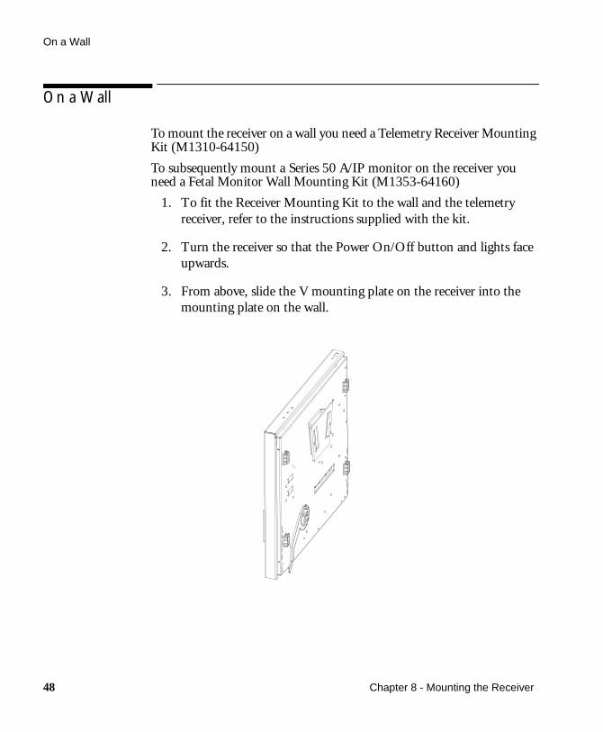
To mount the receiver on a wall you need a Telemetry Receiver Mounting Kit (M1310-64150)
To subsequently mount a Series 50 A/IP monitor on the receiver you need a Fetal Monitor Wall Mounting Kit (M1353-64160)
1. To fit the Receiver Mounting Kit to the wall and the telemetry receiver, refer to the instructions supplied with the kit.
2. Turn the receiver so that the Power On/Off button and lights face upwards.
3. From above, slide the V mounting plate on the receiver into the mounting plate on the wall.
48 Chapter 8 - Mounting the Receiver

On a Wall
4. Attach the Fetal Monitor Wall Mount to the receiver with 3 screws (A).
5. Mount your monitor on top of the receiver.
Chapter 8 - Mounting the Receiver 49

On a Wall
50 Chapter 8 - Mounting the Receiver

9Maintenance and Performance Assurance
Preventive Maintenance
The following should be routinely performed (approximately every 12 months) by the user or qualified service personnel:
• Mechanical inspection of cables, and connectors to the fetal monitor.Do not use any that show signs of damage.
• Check and clean the transmitter and receiver housings.
For more details on maintenance and performance assurance, refer to the Series 50 T Service Manual.
Care and Cleaning
Keep the outside surfaces of the transmitter and receiver clean and free of dust and dirt. Use soap and water or ETHANOL 70%.
CautionAlthough the transmitter and receiver are chemically-resistant to most common hospital cleaners and non-caustic detergents, different cleaners are not recommended and may stain the transmitter and receiver.Many cleaners must be diluted before use. Follow the manufacturer’s directions carefully to avoid damaging the transmitter and receiver. Never use an abrasive material such as steel wool or metal polish.Do not allow any liquid to enter the transmitter and receiver cases and avoid pouring liquid on the receiver while cleaning. Do not immerse the transmitter.
Chapter 9 - Maintenance and Performance Assurance 51

Testing the Parameter Signals
Testing the Parameter Signals
The parameter test tests the signal path to and from the transducer sockets, but not the transducers themselves.
1. Switch on the monitor, the recorder and the telemetry receiver.
2. Connect the appropriate transducer to each socket on the transmitter.
3. Standing within view of the monitor, press the Nurse Call Button on the transmitter and switch on the transmitter simultaneously. The test runs while the Nurse Call is pressed.
52 Chapter 9 - Maintenance and Performance Assurance

Testing the Parameter Signals
If the response is different, contact your Philips Medical Response Center.
Signal Correct Monitor Response
US 125 is displayed and printed.Signal Quality Indicator is green.Fetal heartbeat is heard from the loudspeaker.
Toco A triangle signal with an amplitude of 40 units is displayed and printed.Each cycle lasts for 12 seconds.
DECG 150 is displayed and printedSignal Quality Indicator is green.Fetal heartbeat is heard from the loudspeaker.
Chapter 9 - Maintenance and Performance Assurance 53

Testing the Receiver
Testing the Receiver
To run the receiver self test:
1. Switch on the monitor and recorder.
2. Press the Power On/Off button to switch the receiver on.
3. When you switch on:
• The receiver On light (A) comes on.
• The nurse call light (B) and the battery low light (D) are lit for one second.
• The transmission INOP light (C) lights and stays lit until the transmitter is switched on.
• The telemetry lamp indicator on the monitor lights, indicating telemetry monitoring mode.
• TELE is annotated on the fetal trace.
54 Chapter 9 - Maintenance and Performance Assurance

Testing the Receiver
Testing the Interface Between the Fetal Monitor and Receiver
1. Remove the fetal monitor interface cable from the back of the receiver.
2. All the lights on the front of the receiver will go out.
If they are still lit the receiver is not working properly.
Contact your Philips Medical Response Centre.
Testing the Interface Cable
1. Connect the interface cable to the receiver.
2. Remove the interface cable from the fetal monitor.
a. If all the lights on the receiver are lit, the interface cable is faulty.
b. If the lights on the receiver go out, the telemetry interface in the fetal monitor is faulty.
Contact your Philips Medical Response Centre.
Chapter 9 - Maintenance and Performance Assurance 55

Testing the Transmitter
Testing the Transmitter
1. Slide back the battery cover.
2. Switch on the transmitter. The green On/Off light (A) comes on showing the transmitter is on.
3. Check the red light (B) situated behind the middle battery. If:
• the red light is lit for a few seconds and then goes out, the self test is successfully complete.
• the red light blinks, or remains on after three seconds, change the batteries. If the fault continues, contact your Philips Medical Response Center.
56 Chapter 9 - Maintenance and Performance Assurance

Battery Life
Battery Life
When the batteries in the transmitter are low, the Battery Low light (A) on the receiver is lit.
Battery Low Lamp
CautionUse only high quality batteries. Remove the batteries if you do not intend to use the transmitter for a long period of time.
Chapter 9 - Maintenance and Performance Assurance 57

Battery Life
Battery Details3 x 1.5VSize: AAType: LR6
Typical Battery Operating Times at Room Temperature
US + TOCO DECG + TOCO DECG + IUP
Aft
er L
ow L
Ight
Com
es O
n
Ope
ratin
gT
ime
Aft
er L
ow L
ight
Com
es O
n
Ope
ratin
gT
ime
Aft
er L
ow L
ight
Com
es O
n
Ope
ratin
gT
ime
Alkaline (1.8 Ah) 180 min 40 hrs 100 min 16 hrs 80 min 14.5 hrs
NiCd (0.6 Ah)Rechargeable
10 min 12 hrs 6 min 5.5 hrs 5 min 4.5 hrs
NiMH (1.2 Ah)Rechargeable
20 min 22 hrs 12 min 11 hrs 10 min 9 hrs
58 Chapter 9 - Maintenance and Performance Assurance

10Troubleshooting
Refer to Chapter 4 for common problems related to the different methods of measuring parameters.
More detailed tests are given in the Service Manual (M1310-9000B).
Solving General Problems
Problem Possible Causes Solutions
All the lights on the receiver stay on when the receiver is turned on.
Fetal monitor is switched off.
Possible defect in the receiver, interface cable or fetal monitor.
Switch on fetal monitor.
Carry out the tests described in Chapter 9, “Testing the Receiver” on page 54.
The Telemetry Indicator Lamp on the fetal monitor does not light when the monitor and the receiver are switched on.
Incorrect interface connection between the monitor and the receiver.
Faulty interface cable.
Follow the instructions in Chapter 3 for details on how to connect the monitor to the receiver.
Replace interface cable.Contact your Philips Medical Response Center.
Receiver Power On Light does not light when the receiver is switched on.
Power cable not plugged into the power supply.
Fuses need replacing.
Line voltage incorrect.
Plug in and switch on.
Replace fuses.
Contact your Philips Medical Response Center.
Chapter 10 - Troubleshooting 59

Solving General Problems
Transmission INOP light on the receiver is still lit when the transmitter is switched on.
Receiver and transmitter do not have the same channel or serial number.
Batteries in the transmitter are exhausted.
Check channel number and the serial numbers are the same on the receiver and the transmitter.
Change the batteries in the transmitter (refer to Chapter 3 for details.)
Battery Low Light lit on receiver.
Power in batteries is low. Change batteries.
INOP transmission lamp is lit after the patient has moved a short distance away form the receiver.
Local Antenna:Antenna not connected correctly.
Remote Antenna System:Antenna cable not connected correctly to receiver.
Check antenna is connecting correctly.
Test the antenna system by bringing the transmitter close to the receiver. If the transmission is good, then the antenna system is not functioning properly.
Contact your Philips Medical Response Center.
Problem Possible Causes Solutions
60 Chapter 10 - Troubleshooting

Error Messages
Error Messages
The following error messages are directly related to telemetry and appear on the fetal monitor. Refer to the Instructions for Use provided with your monitor for error messages not related to telemetry monitoring.
Series 50 Family
Message Display Cause Solution
Err 9 US Toco Invalid telemetry mode. Check the cable from the telemetry receiver and, if necessary, replace it.
Err 14 US Toco Incorrect transducer connected to transmitter.
Check that the transducer is compatible with Series 50T Fetal Telemetry System.
Err 16 US Toco Transducers are connected to the front panel of the monitor.
Disconnect the transducers from the monitor or switch off the telemetry receiver.
Chapter 10 - Troubleshooting 61

Error Messages
8040A
8041A
Message Display Cause Solution
Err 16 US Toco Transducers are connected to the front panel of the monitor.
Disconnect the transducers from the monitor or switch off the telemetry receiver.
Message Display Cause Solution
Signal indicator lamps flashing
Indicator Panel
Invalid telemetry mode.
Incorrect transducer connected into transmitter. (Only Ultrasound and Toco transducers can be used).
Transducers are connected to the front panel of the monitor.
Check the cable from the telemetry receiver and, if necessary, replace it.
Check that the transducer is compatible with Series 50T Fetal Telemetry System.
Disconnect the transducers from the monitor or switch off the telemetry receiver.
62 Chapter 10 - Troubleshooting

11Accessories and Technical Specifications
For detailed information regarding accessories and how to use them, refer to your fetal monitor’s Instructions for Use. Refer also to any instructions that accompany the accessories. This chapter contains additional information related to the Series 50 T.
This chapter contains information current at the time of printing.
CautionDo not use accessories that are not approved by Philips. You may damage the equipment and this type of damage is not covered by warranty.
Chapter 11 - Accessories and Technical Specifications 63

Compatible Accessories
Compatible Accessories Accessories Compatible with Series 50 T (M1310A)
DescriptionProduct No./
OptionPart No.
Ultrasound, Toco and DECG Accessories
Toco Transducer Standard Series 50 transducers with a long (2.5m/8ft 2in) cable, blue, watertight to IEC 529 (IP 68)
M1355A M1355-60011
Ultrasound transducer M1356A M1356-60011
DECG Patient Module Long (2.5m/8ft 2in) cable
M1364A M1364-60001
DECG Legplate Transducer
M1357A -
DECG Adapter M1347A -
Toco Transducer Telemetry tranducers with a short (70 cm/28in) cable, blue, watertight to IEC 529 (IP 68)
M1355A Opt. C03 M1355-60013
Ultrasound Telemetry Transducer
M1356A Opt. C03 M1356-60013
DECG Patient Module Short (70 cm/28in) cable M1364A M1364-60003
IUP Transducers
Pressure Transducer CPJ840J5 -
Single-use Sterile Dome CPJ84022 -
Transducer Holder CPJ84046 -
Pressure Transducer 1290C -
IUP Catheters
Disposable Intrauterine Sensor-Tip Pressure Catheter M1333A (worldwide) -
M1333E (USA only) -
Connector Cable(5µV/V/mmHg)
For use with M1333A/E M1334A -
64 Chapter 11 - Accessories and Technical Specifications

Compatible Accessories
Disposable Intrauterine Transducer-Tipped Pressure Catheter
13975B -
13995A -
DECG Cables
DECG Cable For M1364A patient module (open-wire)
M1362A -
DECG Adapter Cable For M1364A patient module
M1362B -
Disposable Fetal Scalp Electrodes
Double Spiral Electrode 15133D (Europe) -
Single Spiral Electrode 15133E (USA) -
Marker
Remote Event Marker 15249A -
Accessories Compatible with Series 50 T (M1310A)
DescriptionProduct No./
OptionPart No.
Chapter 11 - Accessories and Technical Specifications 65

Technical Specifications
Technical Specifications
Technical Specifications
General
Environment Operating Temperature 0 to +45°C
Storage Temperature -40° to +75°C
Relative Humidity 5 to 95%
Receiver
Power Operating Voltage 100 to 120Vor 220 to 240V (± 10%)
Line Frequency 50 to 60Hz
Power Consumption 19 VA max
Input Sensitivity -118dBm
Dimensions and Weight Height 50mm (2in)
Width 425mm (16.7in)
Depth 392mm (15.4in)
Weight 6.5kg (14.3 lb)
Transmitter
Output Power USA 4 mW
Europe 2 mW
Japan 1 mW
Image Rejection >80 dB
Batteries 3x1.5V (AA size, LR6 type)
Dimensions and Weight without transducers and batteries
Height 120mm (4.8in)
Width 85mm (3.3in)
Depth 40mm (1.6in)
Weight 200g (8oz)
66 Chapter 11 - Accessories and Technical Specifications

Declaration of Conformity
Declaration of Conformity
These medical devices comply with the requirements of the Medical Devices Directive (93/42/EEC) concerning medical devices.
This symbol defines Class 2 radio equipment per 1995/5/EC for which Member States may apply restrictions on putting the device into service or placing it on the market. This device is intended to be connected to the publicly available interfaces (PAI) for use throughout the EEA.
These medical devices comply with the Radio and Telecommunications Terminal Directive (1999/5/EC).
This product is classified as Class IIb in accordance with Annex IX of the Medical Devices Directive (93/42/EEC).
Manufactured by: Philips Medizinsysteme Boeblingen GmbH
Hewlett-Packard Str. 2, Boeblingen, Germany
Product Name and Model Number:
Series 50 T (M1310A) Fetal Telemetry System (all options)
Standards complied with:
Safety, Performance EN 60601-1:1990
Systems EN 60601-1-1:1993
Radio EN 300 220-3:2000
EMC EN 60601-1-2:1997
Chapter 11 - Accessories and Technical Specifications 67

Declaration of Conformity
68 Chapter 11 - Accessories and Technical Specifications

Index
A
accessoriescompatible, 64
antennaassembling, 19connecting remote, 19
artifactson Toco trace, 33
B
batteriesinserting, 24life, 57size, 66type, 66
C
care and cleaning, 51channel frequency label, 11,
13checking, 18, 27
compatible accessories, 64compatible fetal monitors, 10connecting
power, 23remote antenna, 19the receiver to the fetal
monitor, 21
D
declaration of conformity, 67
E
environment, 5error messages, 61event marker
marking events, 37
F
fetal monitorscompatible, 10
fetal movement, 35FHR
monitoring problems using US, 33
FHR with ultrasoundmonitoring problems, 33
FMP, 35artifact, 33, 35
I
interfacetesting, 55
IUPproblems when
monitoring, 33
M
maintenancepreventative, 51
marking events, 37maximum input/output
voltages, 8monitoring
FHRproblems using US, 33
IUPproblems, 33
solving common problems, 33Toco
problems, 33under water, 25
mounting the receiveron a flat suface, 46on a wall, 48on top of 8040A, 46on top of a mobile cart, 46on top of Series 50, 47
under a fetal monitor, 43, 44under an angle mount, 45
N
Nurse Callhow to use, 41setting the volume, 42
O
operatingenvironment, 5temperatures, 5
overviewapplication, 15product, 11
P
parameter test, 52patient safety, 5problems
solving general, 59protective earth, 7
R
receiver, 11, 12connecting power, 23testing, 54
remote event markermarking events, 37
S
safety, 1self test
receiver, 54transmitter, 56
setting up
Index 69

receiver, 21, 23transmitter, 24
signal quality indicatorultrasound monitoring, 30
specifications, 66general, 66receiver, 66transmitter, 66
storagetemperatures, 5
T
testinginterface between the
monitor and receiver, 55
parameter test, 52receiver self test, 54transmitter self test, 56
Tocotrace artifacts, 33
traceerratic, 33
transducersand underwater
monitoring, 25applying to patient, 25compatible with telemetry, 64watertight blue, 5, 25
transmitter, 13, 14inserting batteries, 24testing, 56
U
ultrasoundproblems when
monitoring, 33underwater monitoring, 25unpacking the telemetry
system, 17uterine activity
problems when monitoring using Toco, 33
V
voltage settingchecking, 23
70 Index